Microhard Systems VIP4GABGN20 LTE Ethernet Bridge / Serial Gateway User Manual 1 of 2
Microhard Systems Inc LTE Ethernet Bridge / Serial Gateway 1 of 2
UserManual.wiki
>
Microhard Systems
>
VIP4GABGN20 User Manual
>
User Manual 1 of 2
Contents
1.
User manual
2.
User Manual 1 of 2
3.
User Manual 2 of 2
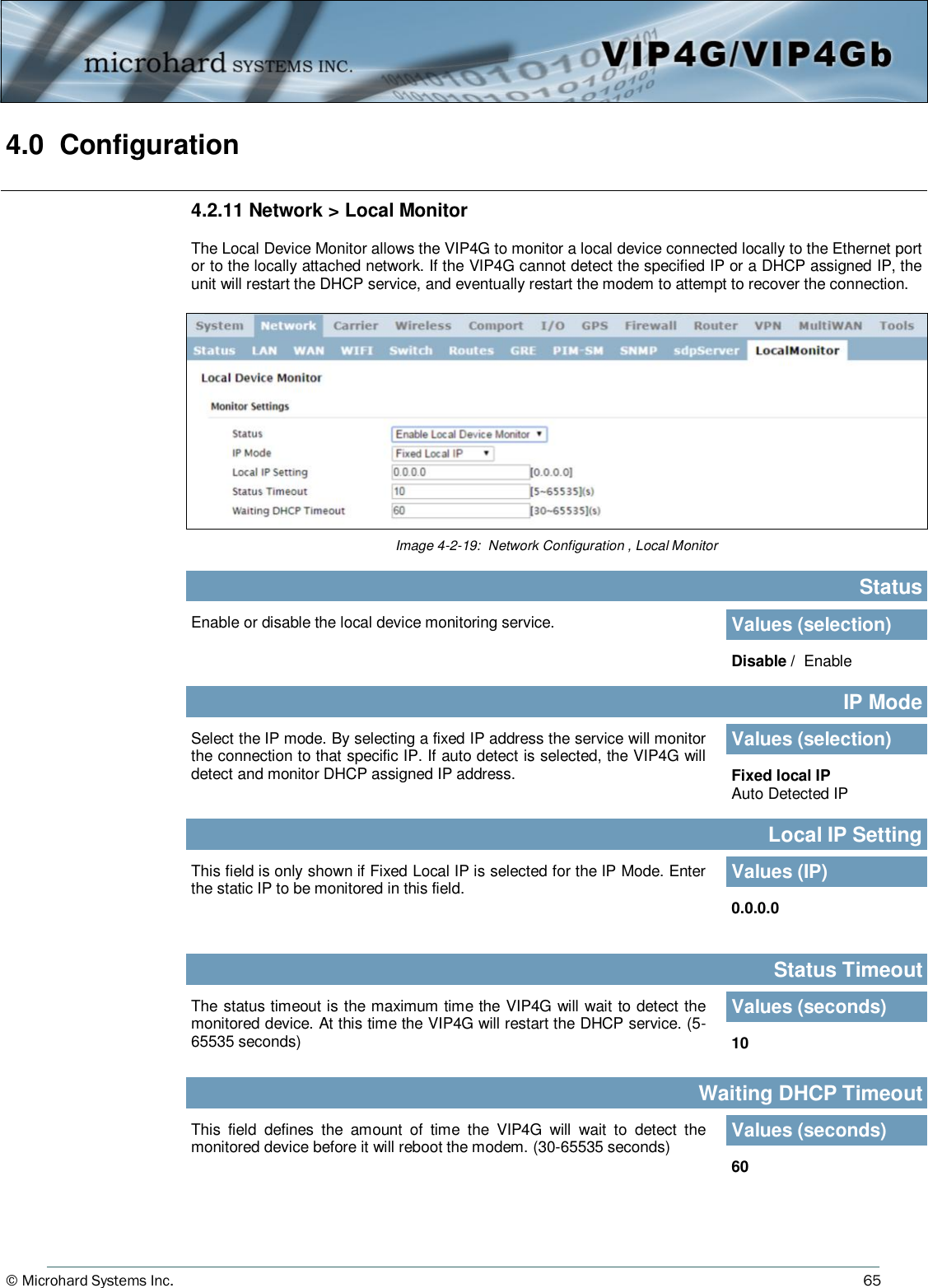
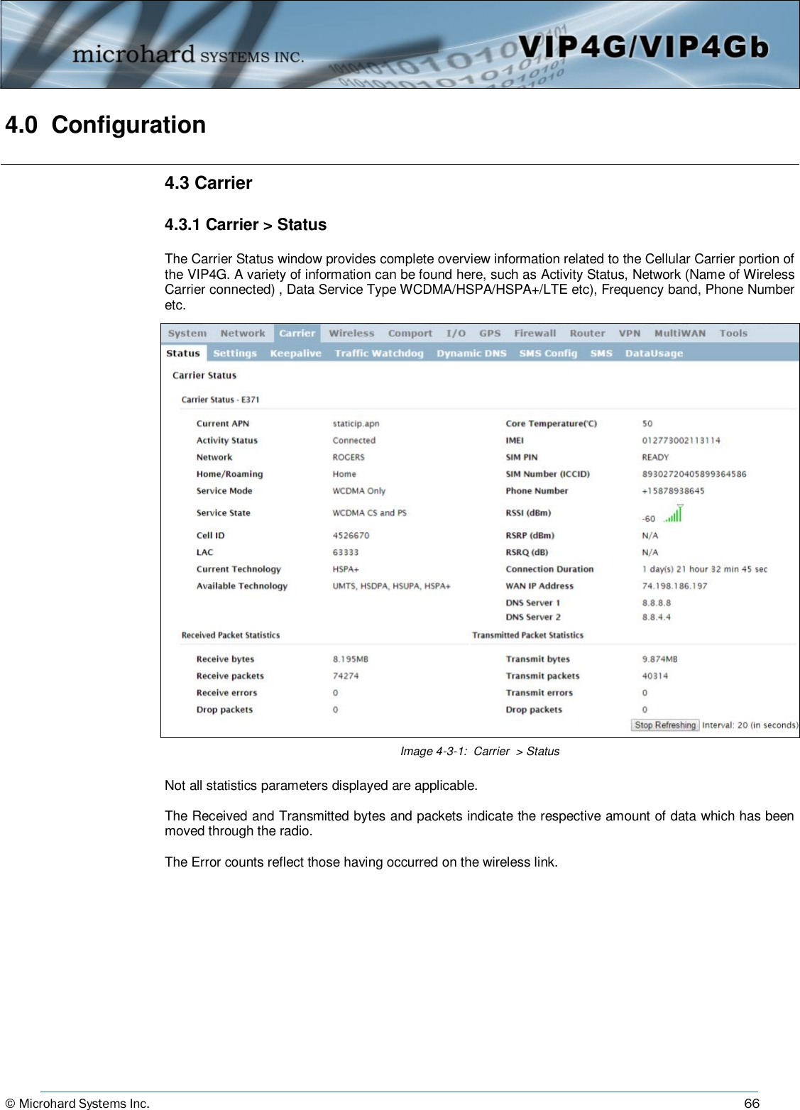
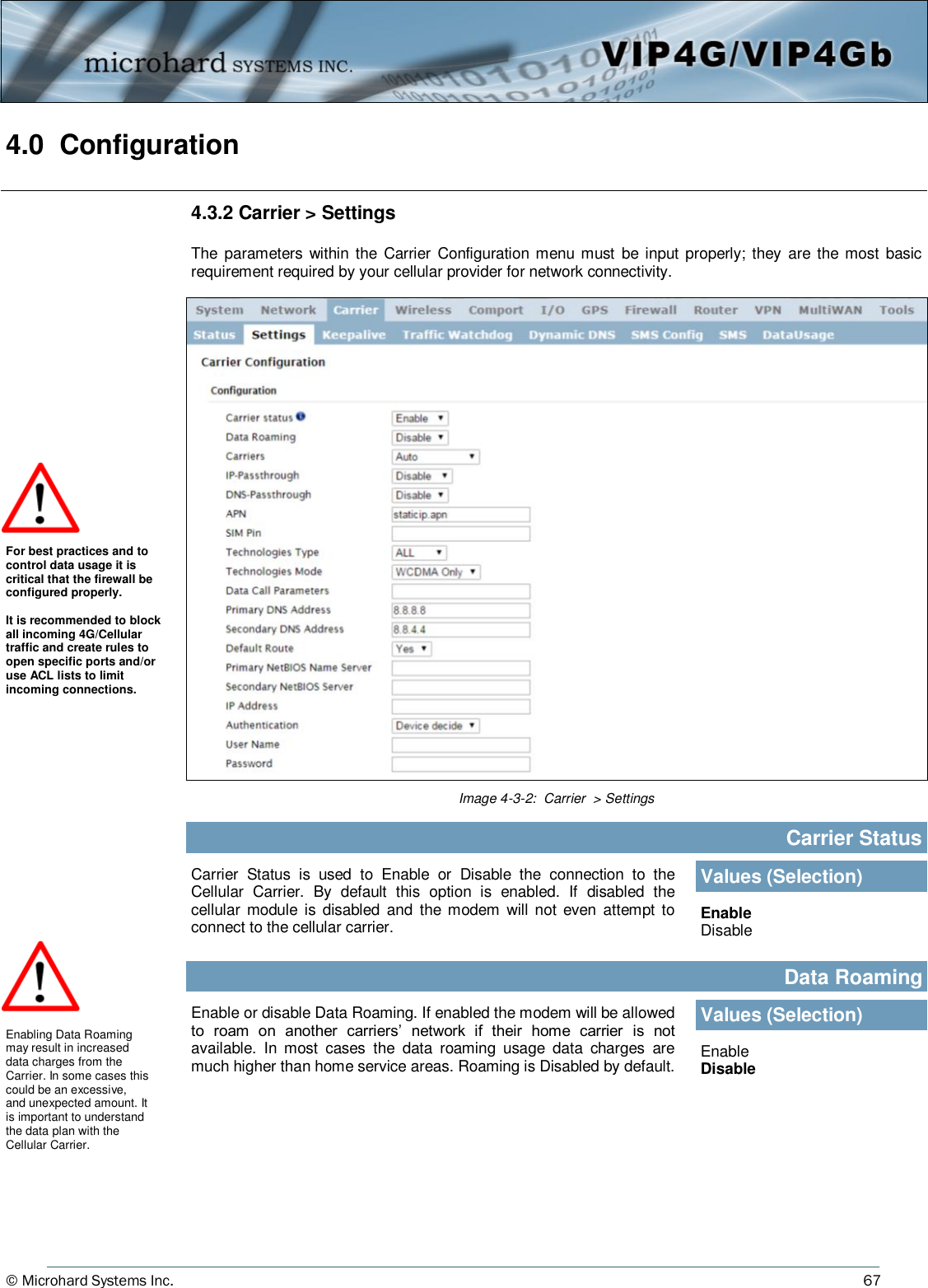
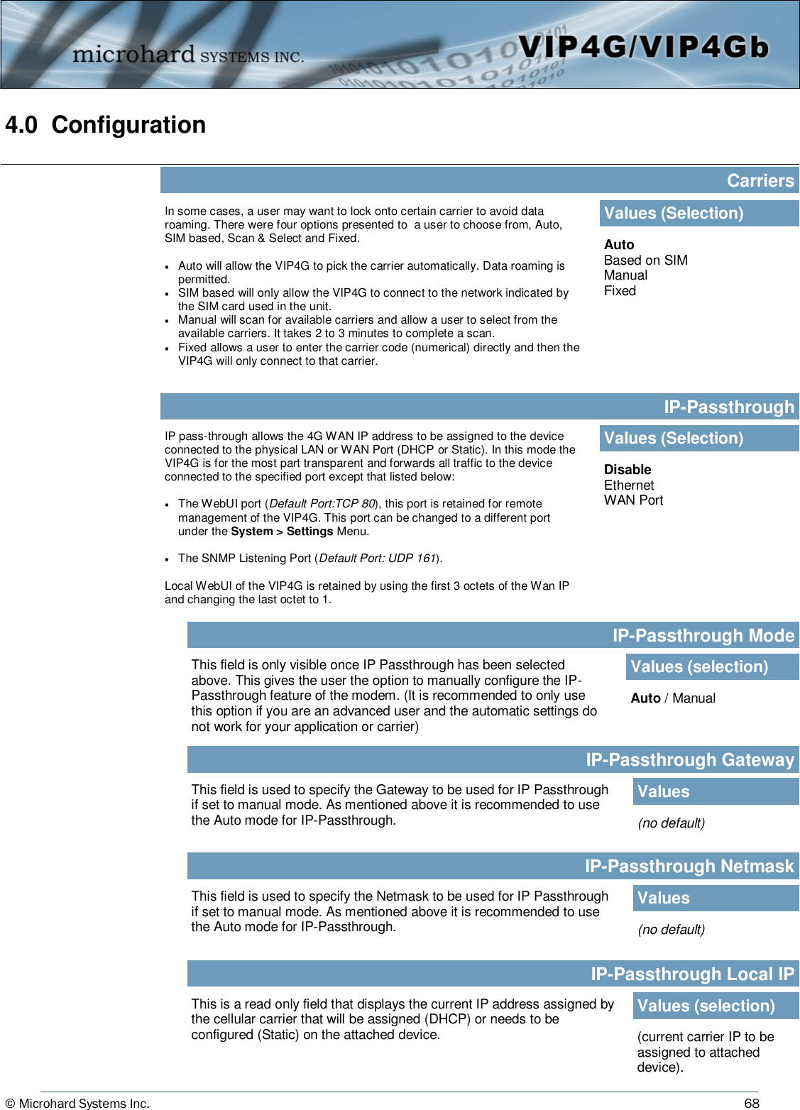
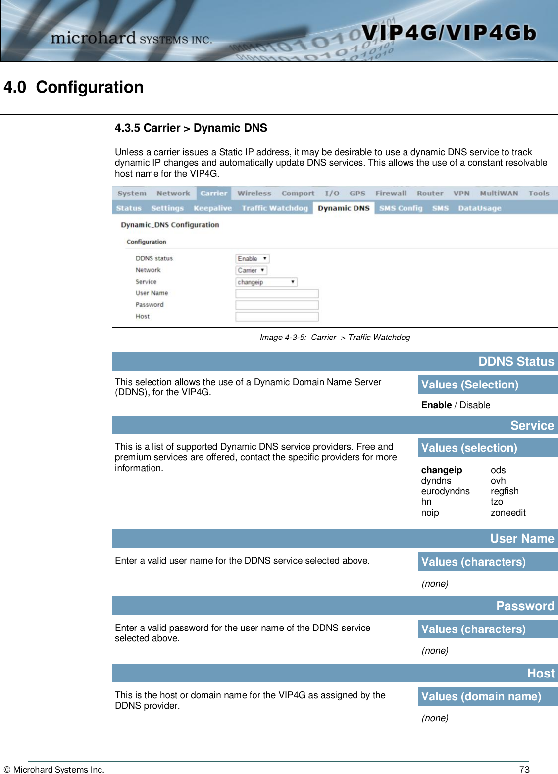
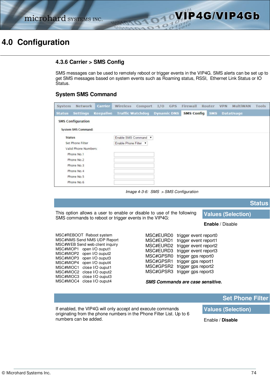
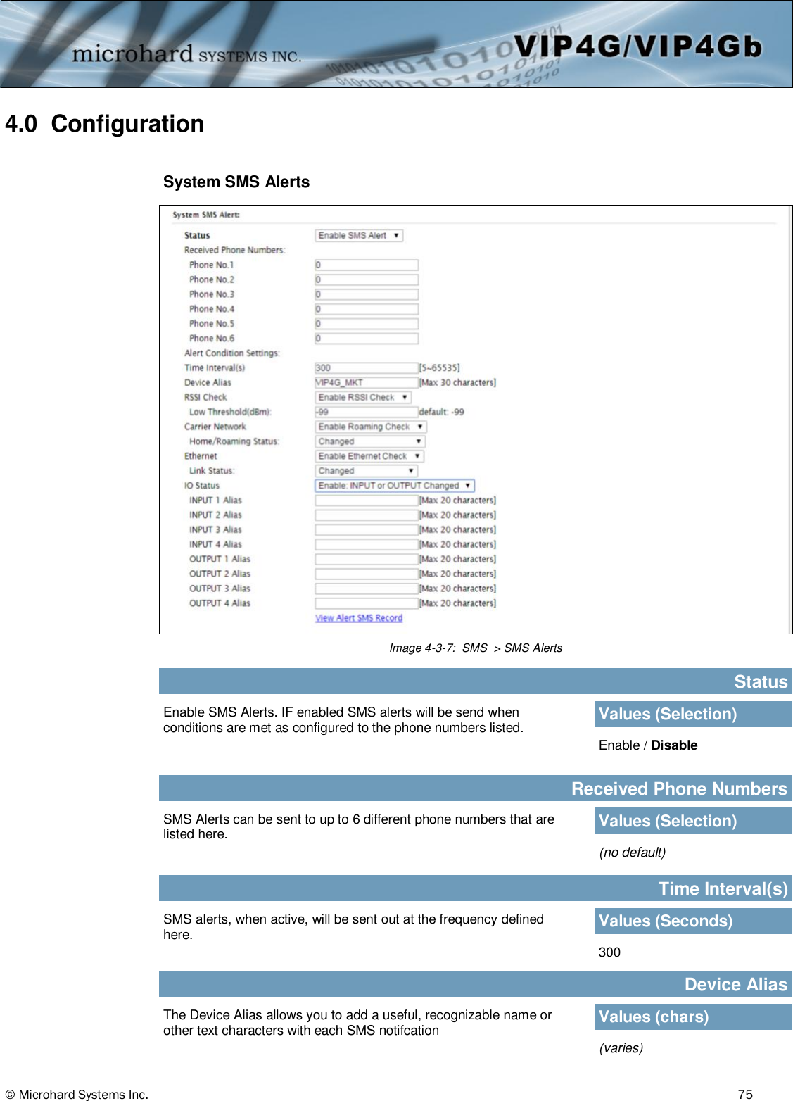
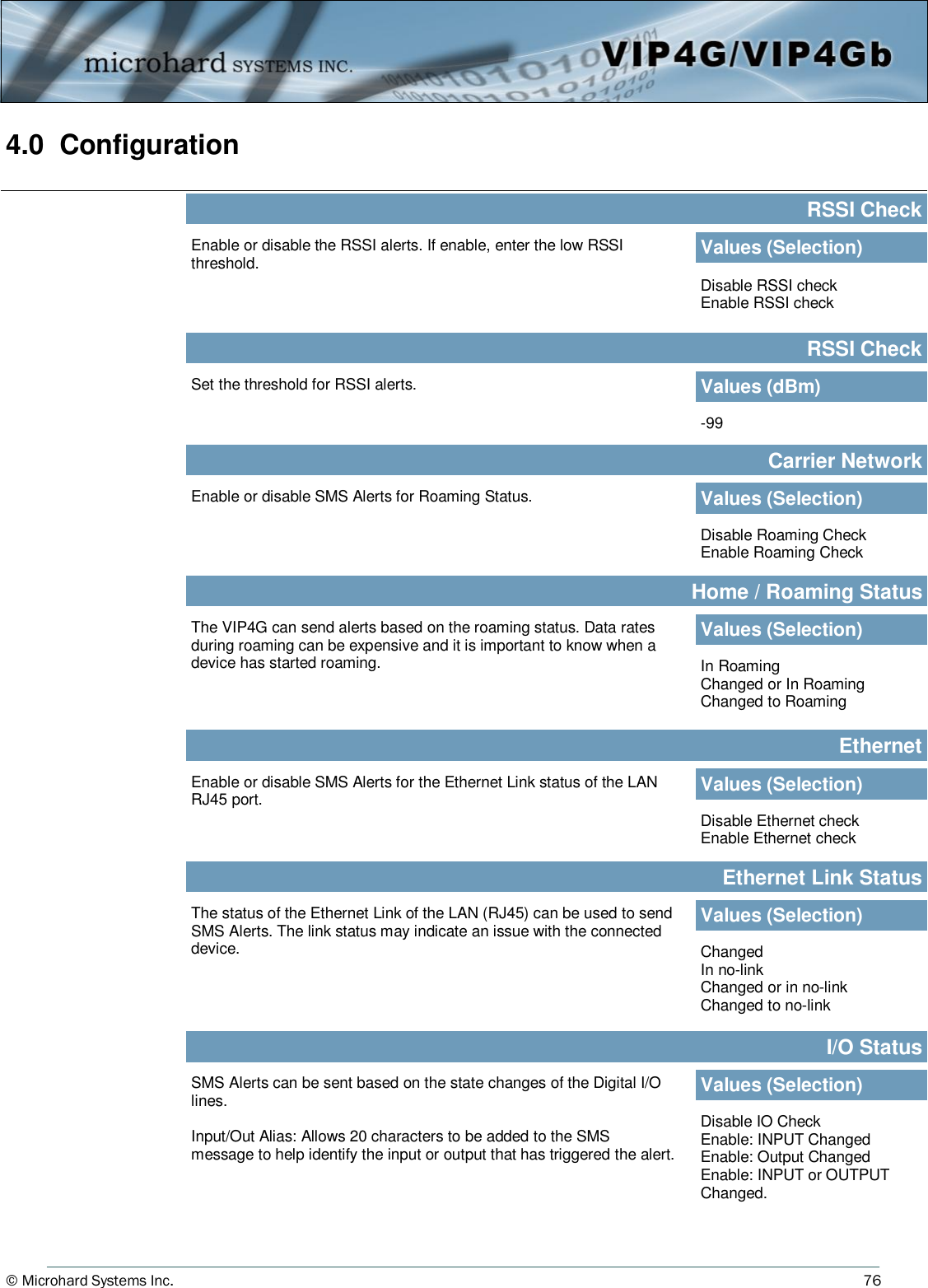
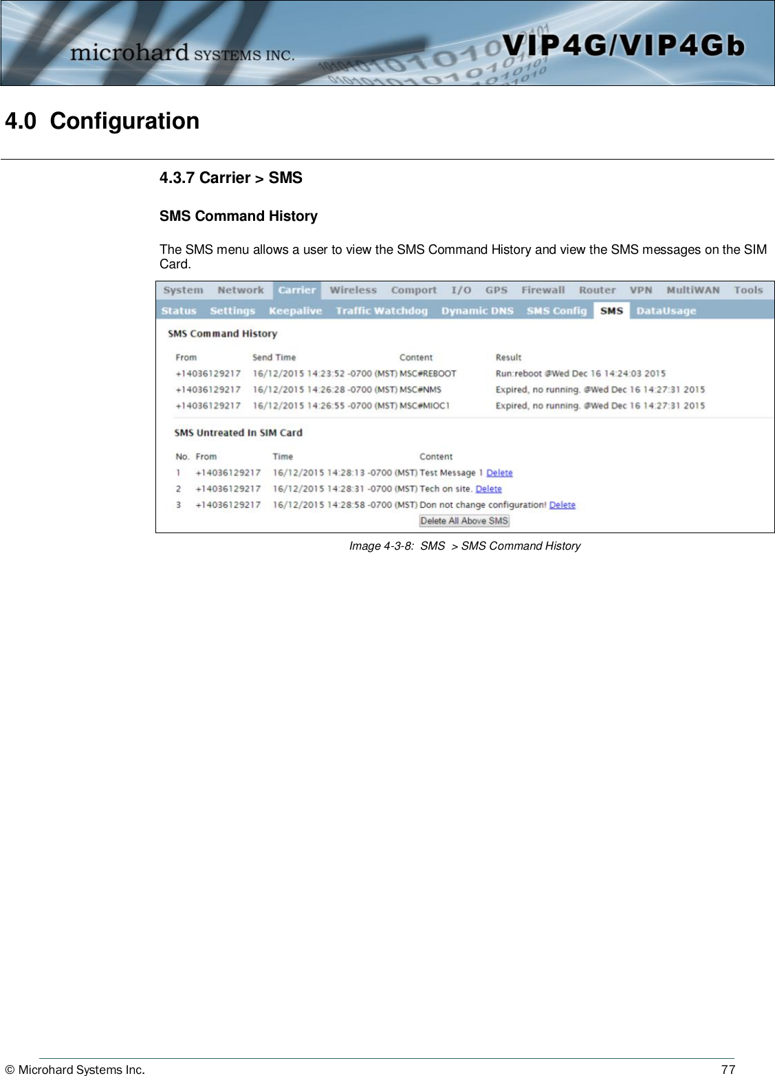
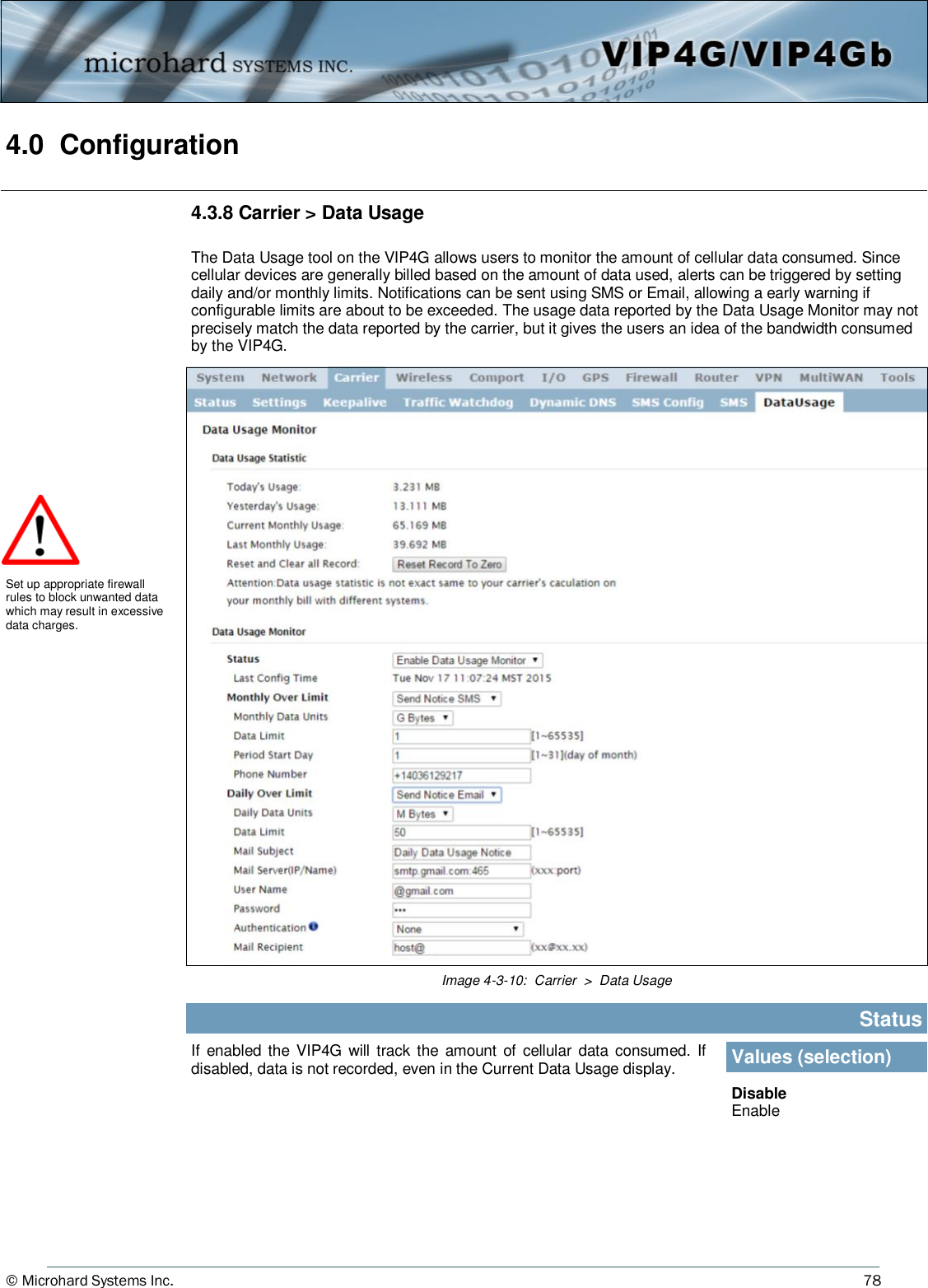
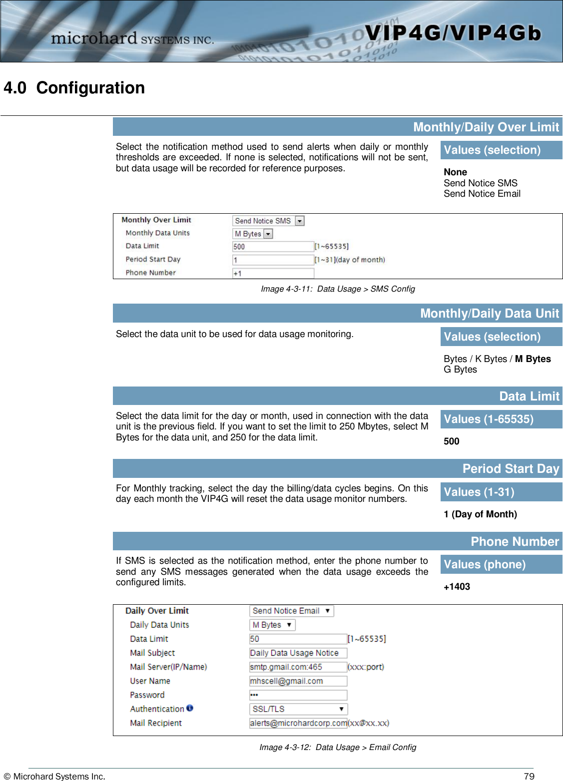
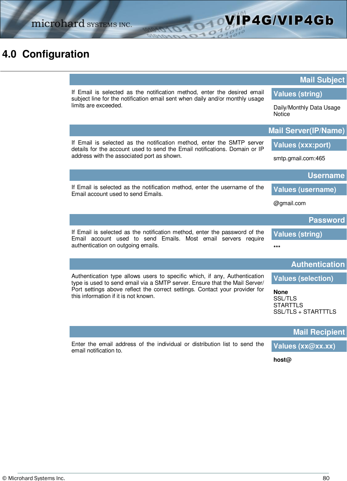
User Manual 1 of 2
Navigation menu
Upload a User Manual
Namespaces
Wiki Guide
HTML
PDF
Info
Views
User Manual
Discussion / Help
Navigation