Mindray BIO Medical electronics TD608FE Telemetry Transmitter User Manual 608M FDA
Shenzhen Mindray BIO-Medical electronics Co.,LTD. Telemetry Transmitter 608M FDA
UserManual.wiki
>
Mindray BIO Medical electronics
>
TD608FE User Manual
User Manual
Navigation menu
Upload a User Manual
Namespaces
Wiki Guide
HTML
PDF
Info
Views
User Manual
Discussion / Help
Navigation

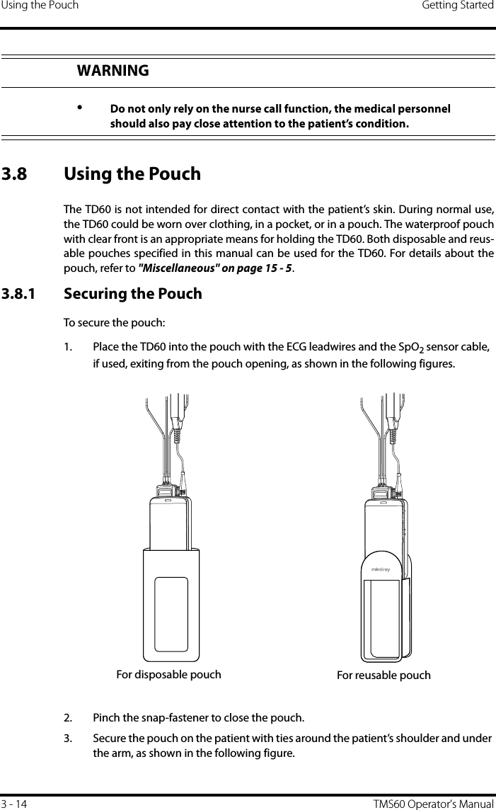
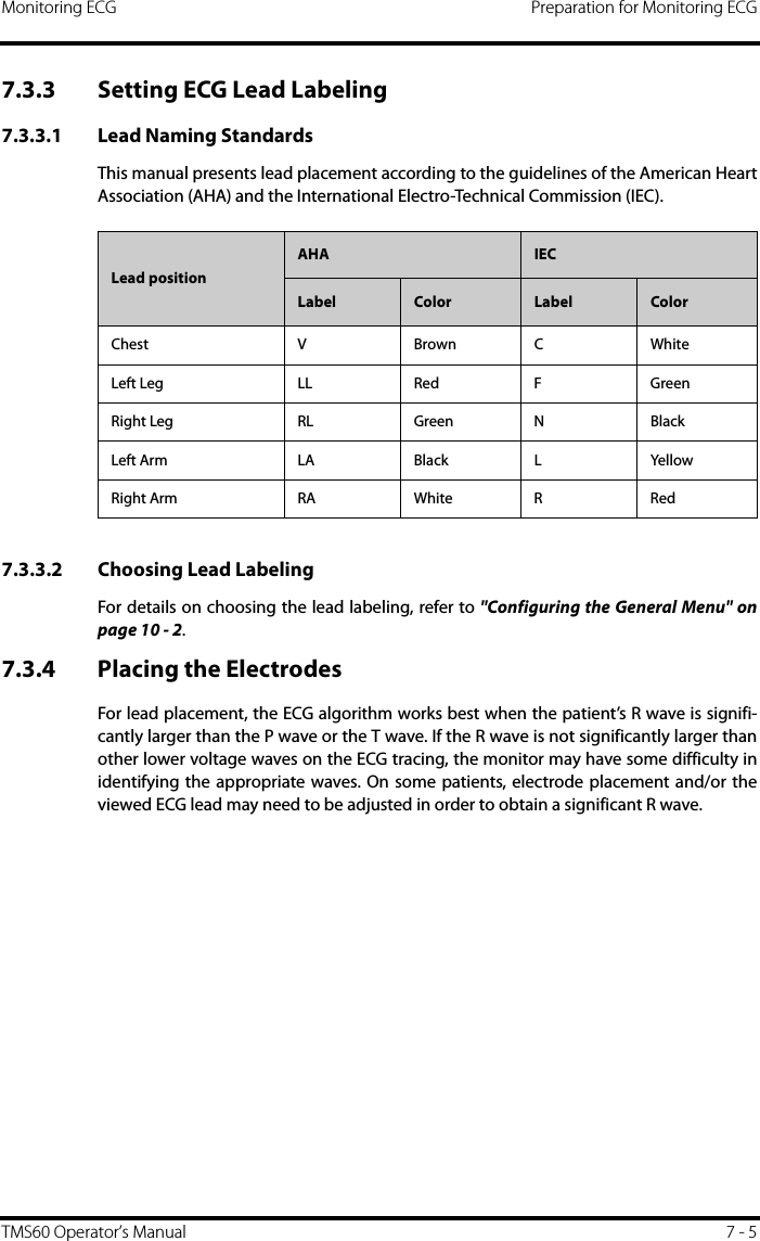
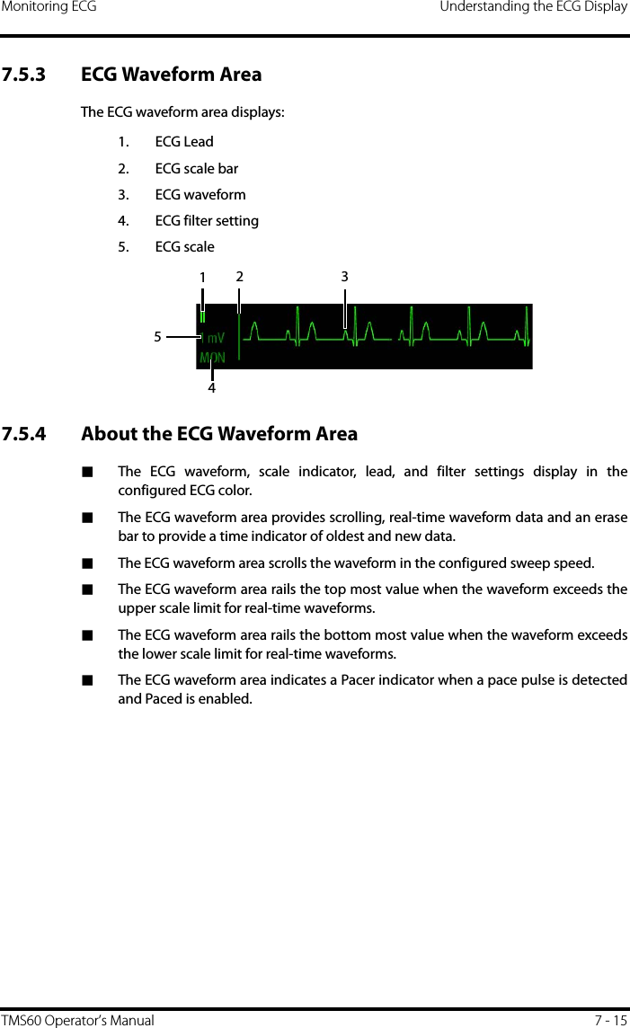
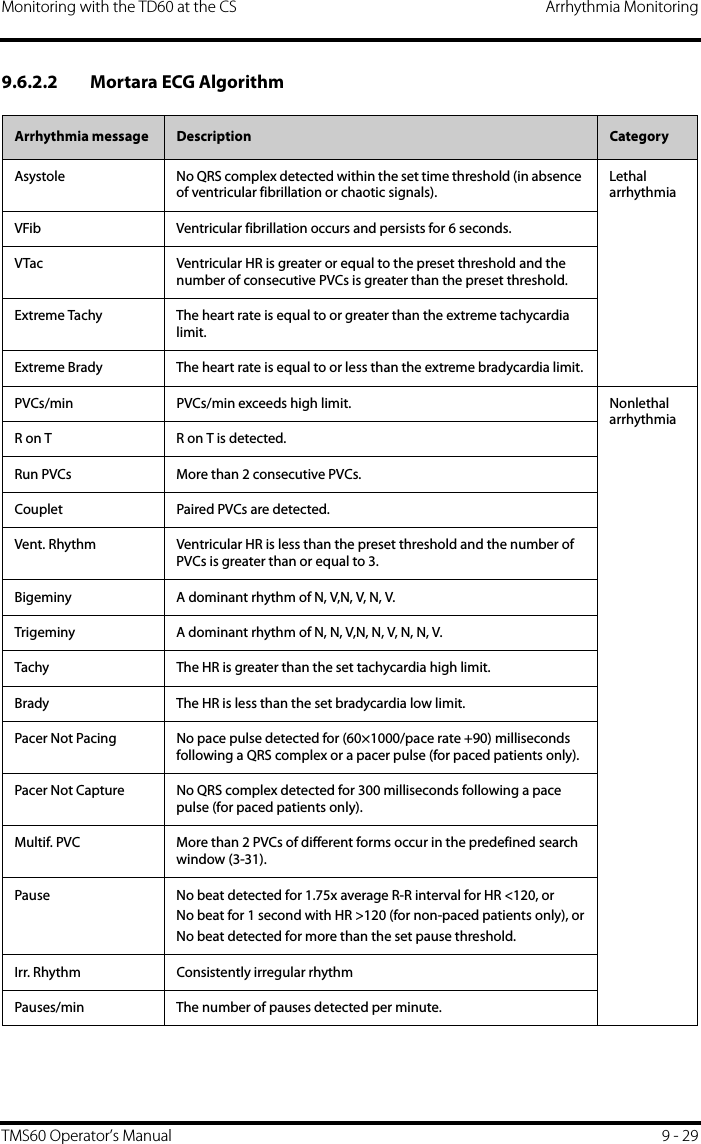
![Introduction PrefaceTMS60 Operator’s Manual VPrefaceManual PurposeThis manual contains the instructions necessary to operate the product safely and in accordance with its function and intended use. Observance of this manual is a prerequisite for proper product performance and correct operation and ensures patient and operator safety.This manual is based on the maximum configuration and therefore some contents may not apply to your product. If you have any questions, please contact Mindray.This manual is an integral part of the product. It should always be kept close to the equipment so that it can be obtained conveniently when needed. Intended AudienceThis manual is geared for clinical professionals who are expected to have a working knowledge of medical procedures, practices and terminology as required for monitoring of critically ill patients.IllustrationsAll illustrations in this manual serve as examples only. They may not necessarily reflect the setup or data displayed on your patient monitor.Conventions■Italic text is used in this manual to quote the referenced chapters or sections.■[ ] is used to enclose screen texts.■→ is used to indicate operational procedures.Fax: 0049-40-255726](https://usermanual.wiki/Mindray-BIO-Medical-electronics/TD608FE/User-Guide-2678251-Page-7.png)

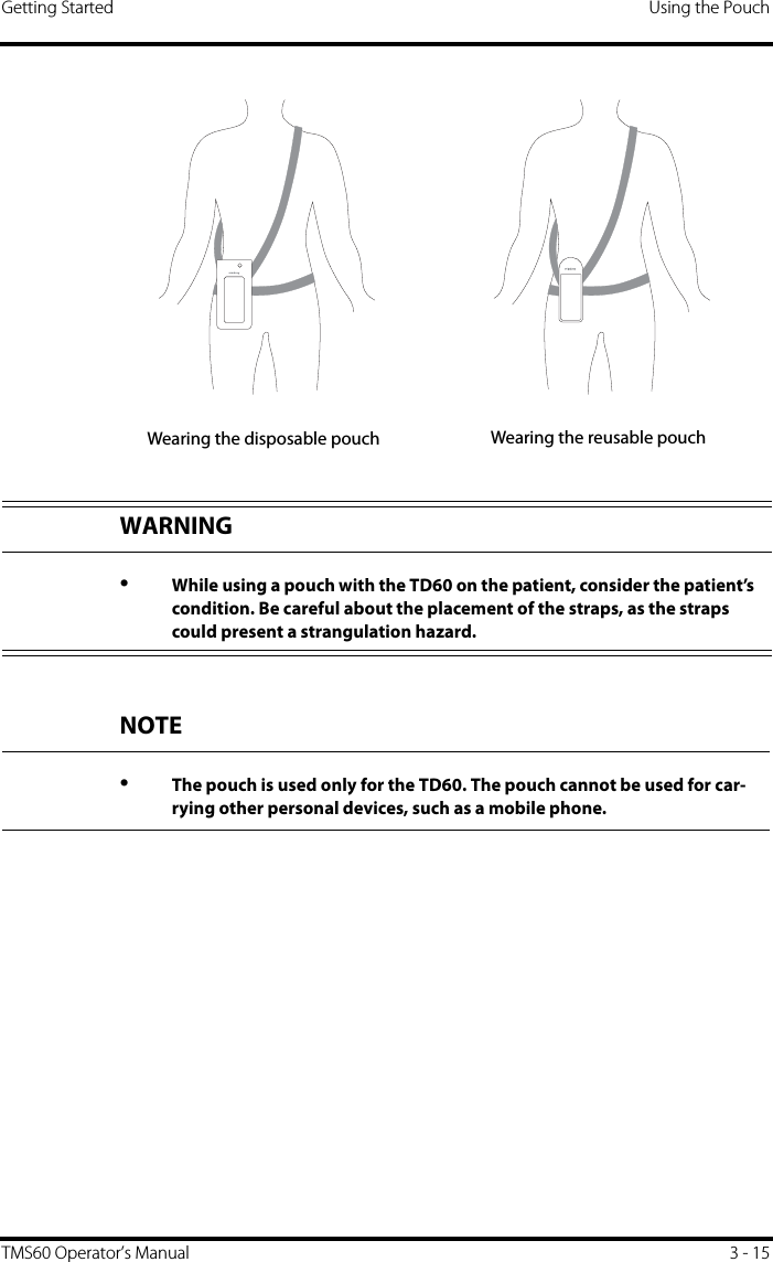
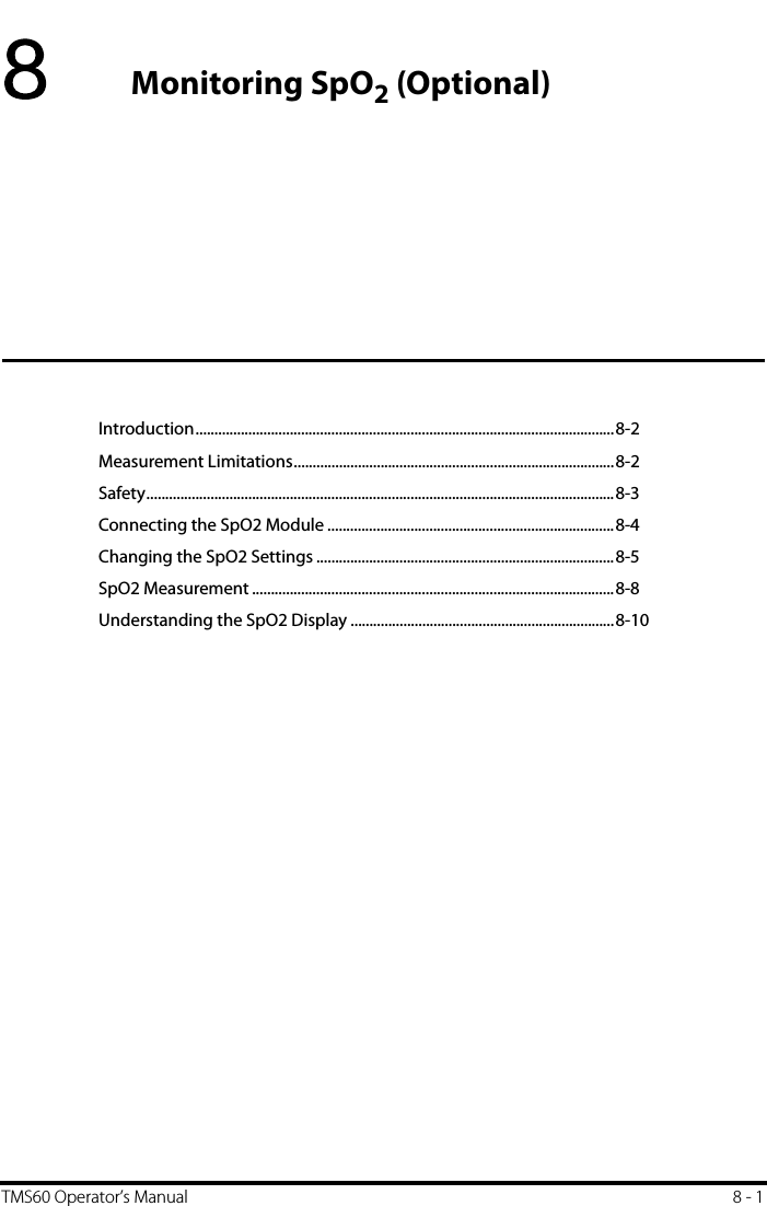
![2 TMS60 Operator’s Manual3.7.10 Acknowledging the Nurse Call ..........................................................................................3 - 133.8 Using the Pouch ........................................................................................................................................3 - 143.8.1 Securing the Pouch ..................................................................................................................3 - 144 User Configurations ................................................................................................................. 4 - 14.1 Introduction ..................................................................................................................................................4 - 24.2 Configuring the Display ...........................................................................................................................4 - 24.2.1 Setting the Default Display Orientation .............................................................................4 - 24.2.2 Understanding Portrait Orientation Display Rules ......................................................... 4 - 24.2.3 Setting the Portrait Display .....................................................................................................4 - 24.2.4 Understanding Landscape Orientation Display Rules ...................................................4 - 34.2.5 Setting the Landscape Display ...............................................................................................4 - 44.2.6 Setting the Display Brightness ...............................................................................................4 - 44.3 Configuring the Audio Volume ............................................................................................................. 4 - 55 Patient Management ............................................................................................................... 5 - 15.1 Introduction ..................................................................................................................................................5 - 25.2 Admitting a Patient .................................................................................................................................... 5 - 25.3 Changing the Patient Category ............................................................................................................. 5 - 25.4 Placing a Device in Standby ...................................................................................................................5 - 35.5 Resume Monitoring ...................................................................................................................................5 - 45.6 Discharging the Patient ............................................................................................................................ 5 - 45.6.1 Selecting the [Discharge Patient] menu .............................................................................5 - 45.6.2 Restarting the TD60 ...................................................................................................................5 - 56 Alarms ....................................................................................................................................... 6 - 16.1 Introduction ..................................................................................................................................................6 - 26.2 Alarm Categories ........................................................................................................................................ 6 - 26.3 Alarm Levels .................................................................................................................................................6 - 26.4 Alarm Indicators ..........................................................................................................................................6 - 36.4.1 Alarm Light .................................................................................................................................... 6 - 36.4.2 Alarm Tones ..................................................................................................................................6 - 36.4.3 Alarm Messages ...........................................................................................................................6 - 46.4.4 Alarm Status Symbols ................................................................................................................ 6 - 46.5 Configuring the Alarms ............................................................................................................................6 - 56.6 Resetting the Alarms ................................................................................................................................. 6 - 57 Monitoring ECG ........................................................................................................................ 7 - 17.1 Introduction ..................................................................................................................................................7 - 27.2 Safety ..............................................................................................................................................................7 - 27.3 Preparation for Monitoring ECG ........................................................................................................... 7 - 37.3.1 Preparing the Patient’s Skin .................................................................................................... 7 - 37.3.2 Positioning the Electrodes .......................................................................................................7 - 3](https://usermanual.wiki/Mindray-BIO-Medical-electronics/TD608FE/User-Guide-2678251-Page-10.png)
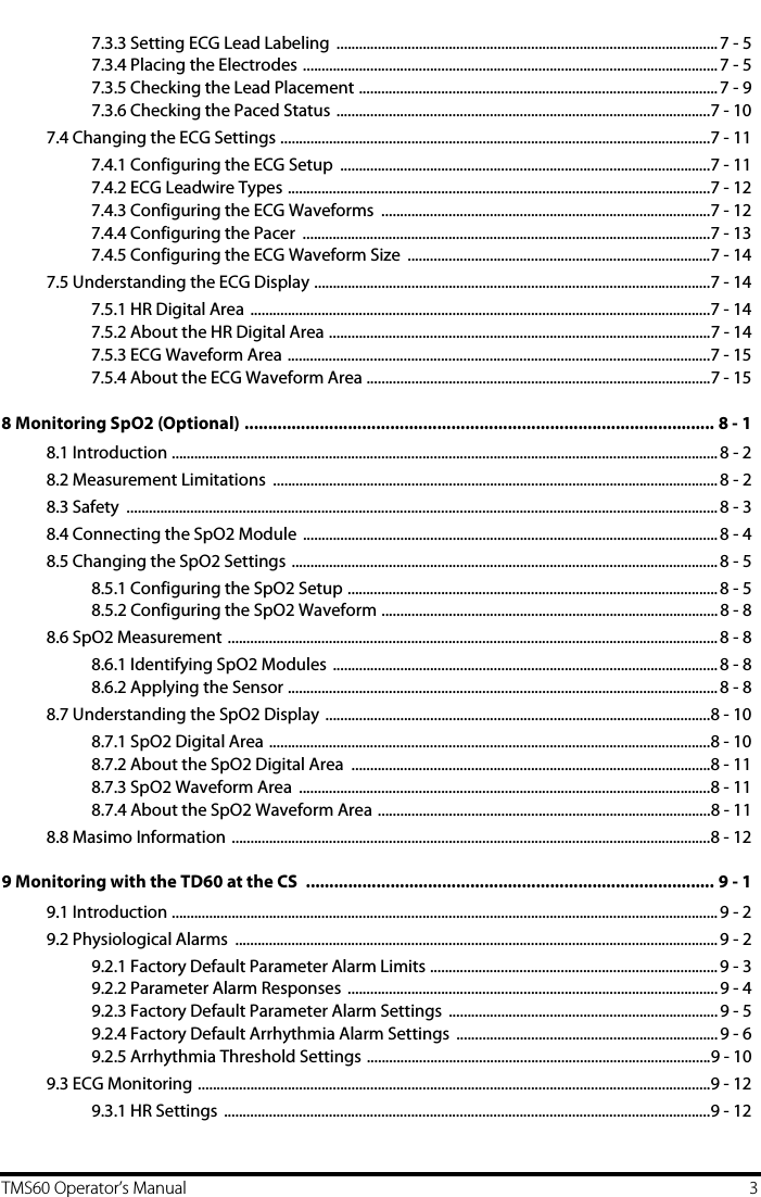

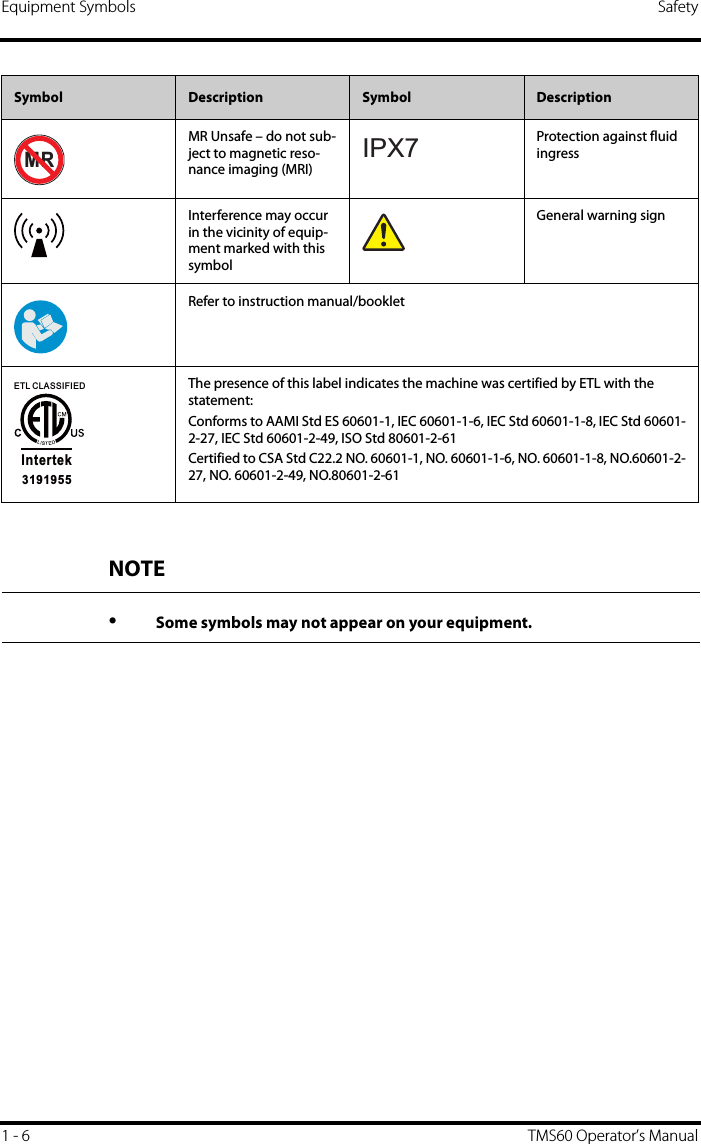
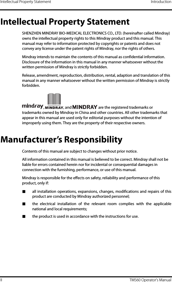
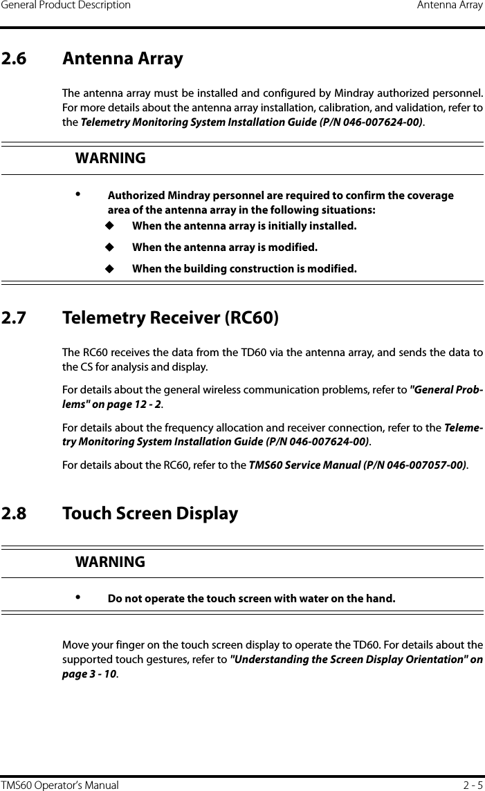
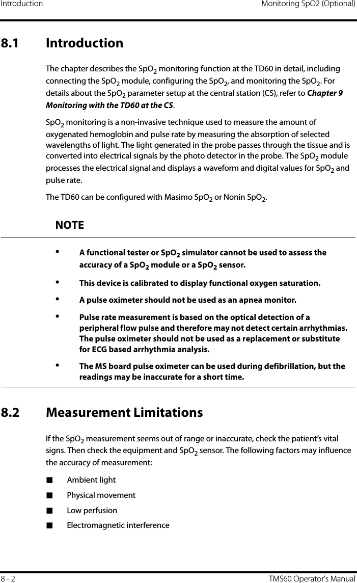
![TD60 Physical View General Product Description2 - 4 TMS60 Operator’s Manual2. Nurse Call keyPressing this key will send a nurse call request to the CS. The alarm light/indicator will illuminate cyan, and a “Nurse Call Initiated” message will display in the mes-sage area if the display is on.3. Main Menu key◆Pressing this key when on the main screen will open the main menu.◆Pressing this key when a menu is open will return to the main screen.◆Pressing this key when the display is off will turn the display on.? Pressing this key when the screen lock mode is configured for View Only willdisplay the [Screen Locked] menu.4. DisplayTouch screen display for viewing patient information and adjusting patient set-tings.5. Alarm light/indicatorFlashes in different color and frequency corresponding to the alarm level.6. ECG connectorECG lead connector.7. SpO2 capCovers SpO2 connector when SpO2 is not in use.8. SpO2 connectorConnects the SpO2 module.9. Speaker10. USB connectorIt is only available for authorized service personnel.11. Battery compartmentContains the lithium-ion battery pack or AA battery tray.](https://usermanual.wiki/Mindray-BIO-Medical-electronics/TD608FE/User-Guide-2678251-Page-24.png)
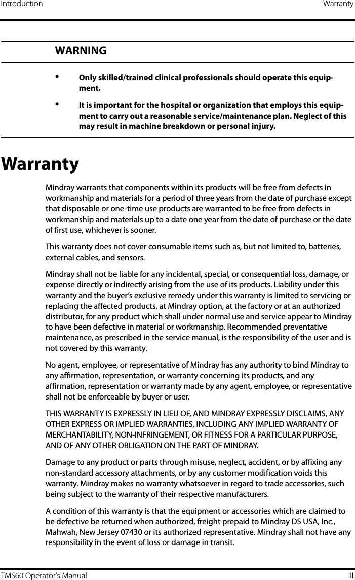
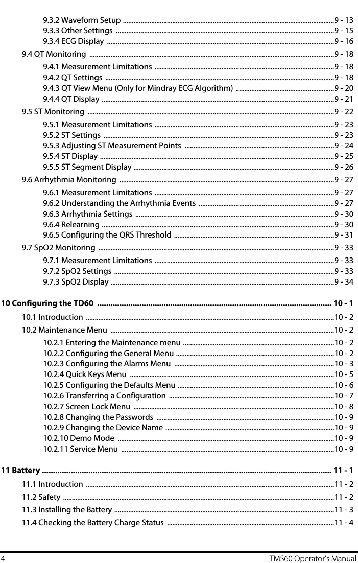
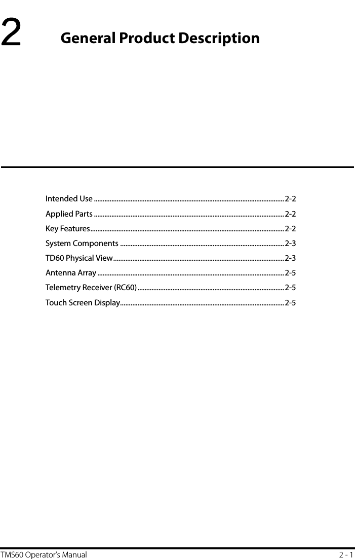
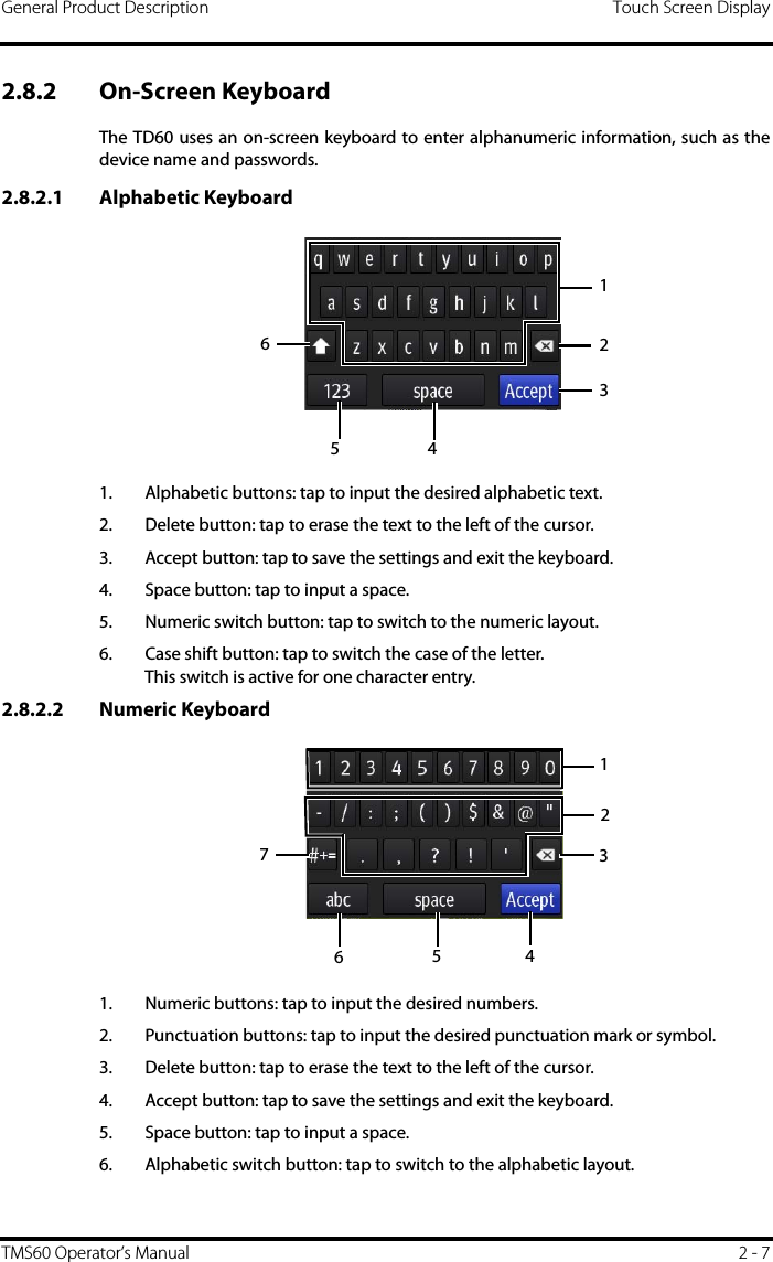
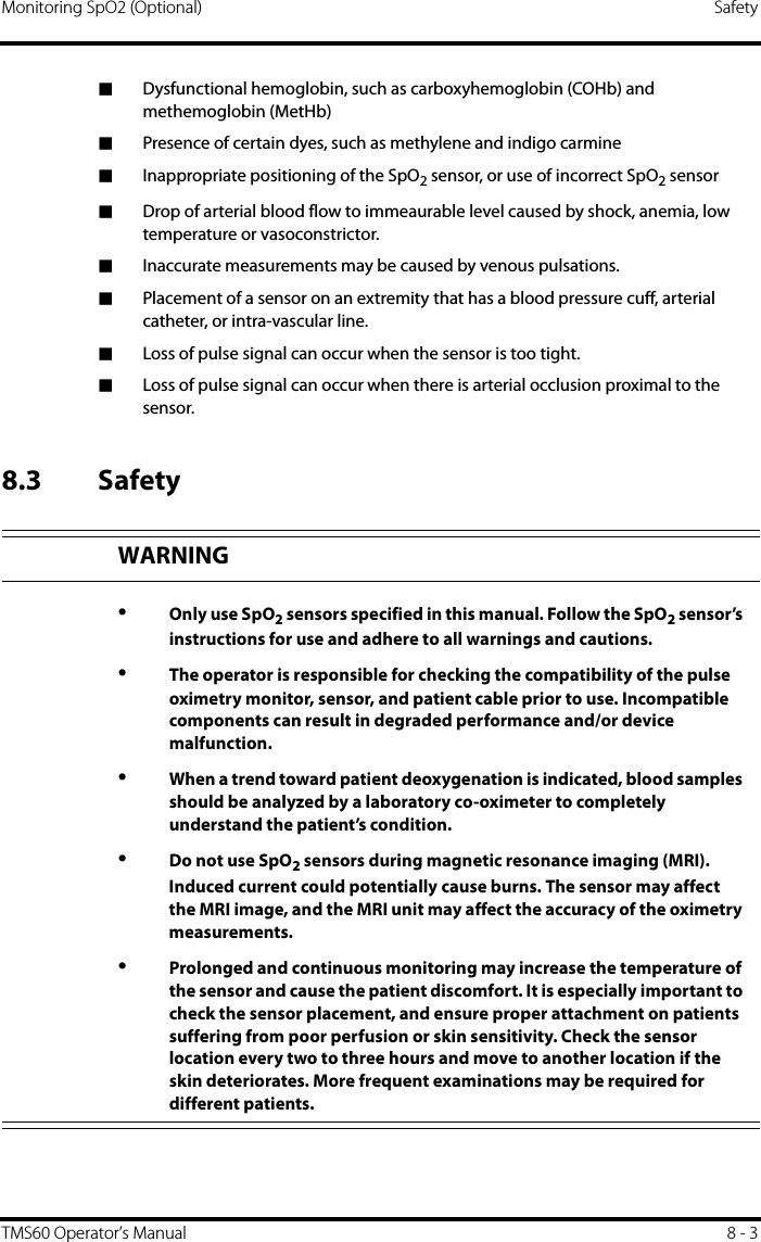
![Touch Screen Display General Product Description2 - 6 TMS60 Operator’s Manual2.8.1 Display ScreenThe main screen displays patient parameters and waveforms. A typical display screen isshown below. 1. Patient information areaThis area shows the patient information such as patient category, device name, and department. Tapping this area displays the [Patient Info] menu.2. Alarm symbols◆ indicates that the alarm system is reset.◆ indicates that the technical alarm audio is turned off.3. Battery symbolThis symbol indicates the battery charge status. Refer to "Checking the Battery Charge Status" on page 11 - 4 for details. Tapping the battery symbol opens the [System Info] menu to the battery section.4. Message areaThis area shows technical alarm messages and informational messages, where there are multiple messages, the messages scroll. 5. Patient data areaThis user configurable area can display parameter/waveform data. The parameter/waveform is labeled in the upper left corner. You may also tap this area to display the Setup menu for the corresponding parameter/waveform. For details about the touch screen operations, refer to "Basic Operations" on page 3 - 9.12345](https://usermanual.wiki/Mindray-BIO-Medical-electronics/TD608FE/User-Guide-2678251-Page-26.png)


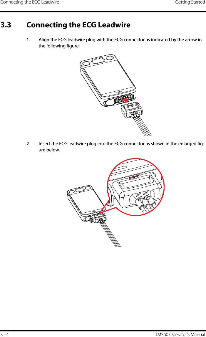
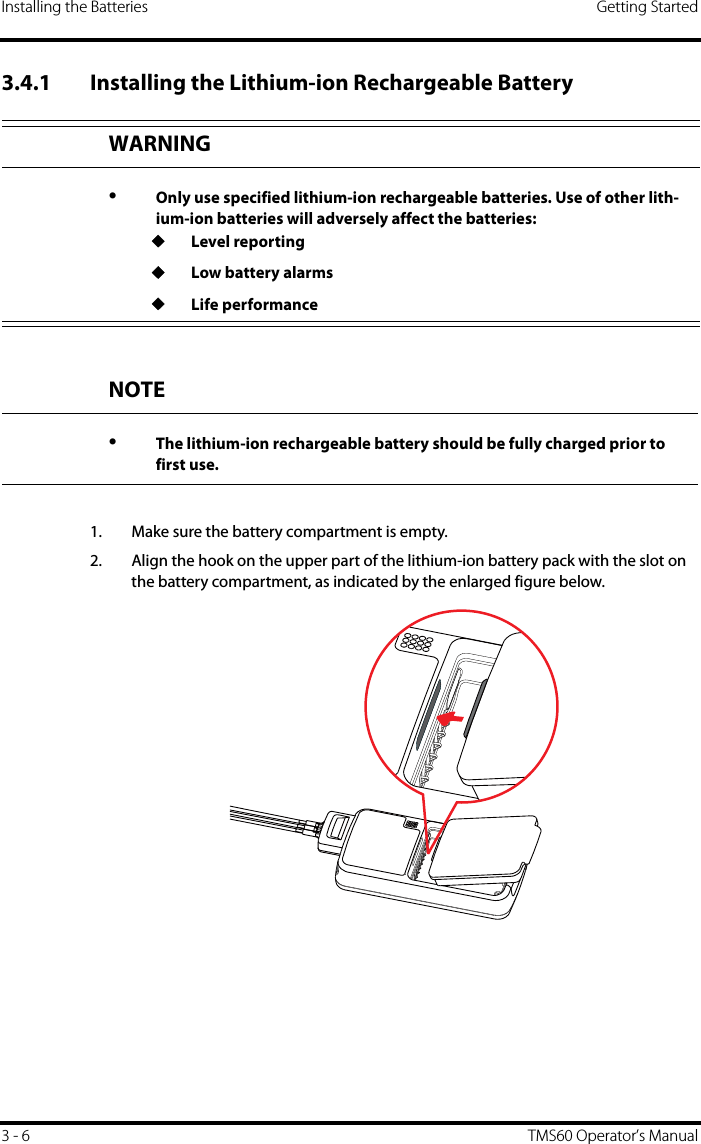
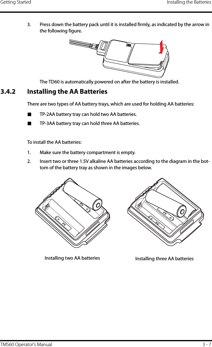
![Powering On the Unit Getting Started3 - 8 TMS60 Operator’s Manual3. Align the hook on the upper part of the battery tray with the slot on the battery compartment, as indicated by the enlarged part in the following figure.4. Press down the battery tray until it closes firmly, as indicated by the arrow in the following figure.The TD60 is automatically powered on after the batteries are installed.3.5 Powering On the UnitPress the key to turn on the TD60. The cyan alarm light will momentarily turn on toindicate that the device is starting. The TD60 performs a self-test during startup. Thedevice sounds a beep, and the alarm light serially turns red, yellow, cyan, and then off.This indicates that the alarm system functions correctly. Upon powering up, there are two situations:■If the TD60 is turned on at first time, the device will request you to configure firsttime startup. Refer to the TMS60 Service Manual (P/N 046-007057-00) for details.■If the TD60 is turned on next time, the device will prompt whether it is a newpatient. Select [Yes] or [No] as desired. If the device is a lock mode, a passcode isrequired.](https://usermanual.wiki/Mindray-BIO-Medical-electronics/TD608FE/User-Guide-2678251-Page-36.png)
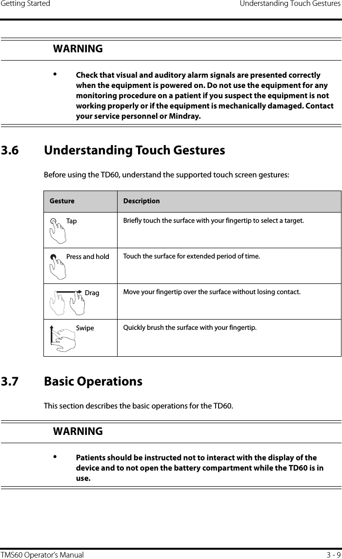
![Basic Operations Getting Started3 - 10 TMS60 Operator’s Manual3.7.1 Understanding the Screen Display OrientationThe TD60 supports both the portrait and landscape display orientations.■Portrait: both digital and waveform tiles take up the entire width of the screen.■Landscape: the digital tile takes up one half of the width of the screen; thewaveform tile takes up the entire width of the screen.3.7.2 Browsing the Screen DisplayTo scroll through the waveforms/parameters, swipe your finger up or down on thescreen.3.7.3 Switching the Screen Display Orientation1. Swipe your finger down from the top of the main screen to display the drop-down menu.2. Tap the desired option to switch the screen display orientation.For example, to switch from portrait display to landscape display:1. Swipe your finger down from the top of the main screen to display the drop-down menu.2. Tap [Landscape] to switch to landscape display.3.7.4 Flipping the Landscape Display1. Swipe your finger down from the top of the main screen to display the drop-down menu.2. Tap [Flip Display] to horizontally flip the landscape display.Example of portrait display Example of landscape display](https://usermanual.wiki/Mindray-BIO-Medical-electronics/TD608FE/User-Guide-2678251-Page-38.png)
![Getting Started Basic OperationsTMS60 Operator’s Manual 3 - 113.7.5 Displaying the Quick Keys AreaSwipe your finger up from the bottom of the main screen to display the quick keys area. The following table lists the six default quick keys:You can customize the most frequently used functions to the quick keys. For detailsabout setting the quick keys, refer to "Quick Keys Menu" on page 10 - 5.3.7.6 Entering the Main MenuPress the key to enter the main menu.The main menu allows access to most of the system functions and settings.Quick keys DescriptionDischarge Patient Tap the button to enter the [Discharge Patient] menu. Refer to "Discharging the Patient" on page 5 - 4 for details.Standby Tap the button to enter the [Standby] menu. Refer to "Placing a Device in Standby" on page 5 - 3 for details.Change Lead Tap the button to change the current first ECG lead waveform to the next ECG lead waveform that is available in sequential order.For example, if the current first ECG lead waveform is I lead, tap the button, the I lead waveform is changed to II lead waveform.Print Tap the button to notify the central station (CS) to start real-time print. The “Print Initiated” message displays on the screen. Manual Event Tap the button to notify the CS to save the event to the event database. The “Manual Event” message displays on the screen. Alarm Reset Tap the button to reset the alarm system. Refer to "Resetting the Alarms" on page 6 - 5 for details.4123](https://usermanual.wiki/Mindray-BIO-Medical-electronics/TD608FE/User-Guide-2678251-Page-39.png)
![Getting Started Basic OperationsTMS60 Operator’s Manual 3 - 133.7.8 Turning the Display OnIf the screen is off, press the or key to turn the display on.3.7.9 Unlocking the ScreenIf you set the screen lock, you need to input the correct passcode to unlock the screenafter the display turns off. To unlock the screen in Locked mode:1. If the screen is off, press the or key to turn the display on and access the [Screen Locked] menu.2. Input the passcode to unlock the screen.Once the passcode is entered the screen is temporarily unlocked. If the is pressed or the device times out, the screen will lock again and a passcode must be entered.To unlock the screen in View Only mode:1. If the screen is off, press the or key to turn the display on.2. Press the key to display the [Screen Locked] menu.3. Input the passcode to unlock the screen.Once the passcode is entered the screen is temporarily unlocked. If the is pressed or the device times out, the screen will lock again and a passcode must be entered.For details about setting the screen lock, refer to "Screen Lock Menu" on page 10 - 8.3.7.10 Acknowledging the Nurse CallTo acknowledge the triggered nurse call, tap [Attendant Present] in the main menu.The “Nurse Call Cancelled” message will display in the message area.For details about how to trigger a nurse call, refer to "TD60 Physical View" on page 2 - 3.CAUTION•Do not let the display directly touch the patient when the display is on.](https://usermanual.wiki/Mindray-BIO-Medical-electronics/TD608FE/User-Guide-2678251-Page-41.png)

![Introduction User Configurations4 - 2 TMS60 Operator’s Manual4.1 IntroductionThis chapter describes the configurations available for users to do, such as configuringthe Display Setup, and Audio Volume.4.2 Configuring the DisplayYou can configure the display by setting the display layout, display orientation, andscreen brightness.In the main menu, tap [Display Setup] to enter the [Display Setup] menu.4.2.1 Setting the Default Display OrientationFor details about the display orientation, refer to "Understanding the Screen DisplayOrientation" on page 3 - 10.1. In the [Setup] section of the [Display Setup] menu, tap [Default Orientation].Two buttons display: [Portrait] and [Landscape].2. Tap a button to set the default orientation.The selected orientation displays to the right of [Default Orientation].3. Restart the TD60 to apply the setting.4.2.2 Understanding Portrait Orientation Display RulesIn portrait orientation, both digital and waveform areas take up the entire width of thescreen. Therefore, these parameters will be displayed in the exact order of the [DisplaySetup] menu, provided the sensor is attached and monitoring data. 4.2.3 Setting the Portrait Display1. In the [Portrait] section of the [Display Setup] menu, tap [Rows].Three options display: [2], [3], and [4]. 2. Tap an option to set the row numbers.The selected option displays to the right of [Rows].3. Tap [Portrait Order] to enter the [Portrait Order] menu.4. Tap a parameter or waveform to select it.The icon displays to the right of the selected parameter or waveform.5. Drag the selected parameter or waveform to the desired position, and then release it. 6. Repeat steps 4 and 5 until the desired order is configured.7. Tap the icon to exit the [Portrait Order] menu.](https://usermanual.wiki/Mindray-BIO-Medical-electronics/TD608FE/User-Guide-2678251-Page-46.png)
![User Configurations Configuring the DisplayTMS60 Operator’s Manual 4 - 34.2.4 Understanding Landscape Orientation Display RulesIn landscape orientation, waveform areas take up the entire width of the screen. Digitalareas only take up one half of the width of the screen. The following rules define how thetiles will be laid out:1. The areas shall be displayed in the order of the [Display Setup] menu except the digital area locations shall be optimized to reduce blank tiles.2. A waveform area always takes up the entire width of the screen.3. A digital area always takes up one half of the width of the screen. Therefore, a row with a digital tile in it shall be split into two half tiles.4. A digital area shall not be the only parameter in a row unless an odd number of digital areas exist. In this case, the last digital parameter area shall have one tile on the left side and the right half will be blank.5. Digital areas shall be paired with the next available digital area to satisfy rule 4. This means that a digital area may be moved ahead of a waveform area if a half of a row needs to be filled.For example, if the landscape display rows is set to [3] and the parameter order is as fol-lows:HRECG IECG IIECG IIIECG aVRECG aVFECG aVLECG VSpO2PLETHThe landscape layout displays as follows:HR* SpO2ECG IECG IIECG IIIECG aVRECG aVFECG aVLECG VPLETH*Bold is displaying on screen; non-bold data need to be scrolled to.](https://usermanual.wiki/Mindray-BIO-Medical-electronics/TD608FE/User-Guide-2678251-Page-47.png)
![Configuring the Display User Configurations4 - 4 TMS60 Operator’s Manual4.2.5 Setting the Landscape Display1. In the [Landscape] section of the [Display Setup] menu, tap [Rows].Three options display: [2], [3], and [4].2. Tap an option to set the row numbers.The selected option displays to the right of [Rows].3. Tap [Landscape Order] to enter the [Landscape Order] menu.4. Tap a parameter or waveform option to select it.The icon displays to the right side of the selected parameter or waveform.5. Drag the selected parameter or waveform to the desired position, and then release it.6. Repeat steps 4 and 5 until the desired order is configured.7. Tap the icon to exit the [Landscape Order] menu.4.2.6 Setting the Display Brightness1. In the [Setup] section of the [Display Setup] menu, tap [Display Brightness].The [Display Brightness] menu displays.2. Drag the slider to left or right to adjust the brightness.3. Tap the icon to exit the [Display Brightness] menu.](https://usermanual.wiki/Mindray-BIO-Medical-electronics/TD608FE/User-Guide-2678251-Page-48.png)
![User Configurations Configuring the Audio VolumeTMS60 Operator’s Manual 4 - 54.3 Configuring the Audio VolumeYou can independently set the technical alarm volume, touch screen click, and systolebeep volume. The method for setting the three volumes are the same.To change the volume settings:1. In the main menu, tap [Audio Volume].2. In the [Technical Alarm], [Touch Screen Click], or [Systole Beep] section, drag the slider to the left or right to adjust the volume.3. Tap the icon to exit the [Audio Volume] menu.NOTE•The icon indicates that the audio volume is turned off.•The minimum value for the technical alarm volume depends on the min-imum technical alarm volume, refer to "Configuring the Alarms Menu" on page 10 - 3 for details.](https://usermanual.wiki/Mindray-BIO-Medical-electronics/TD608FE/User-Guide-2678251-Page-49.png)

![Introduction Patient Management5 - 2 TMS60 Operator’s Manual5.1 IntroductionThe chapter describes how to admit a patient, change the patient size, enter and exit theStandby mode, and discharge the patient.5.2 Admitting a PatientWhen admitting a TM80 for the first time, the device must be admitted to the systemthrough the CS. For details about admitting a patient through the CS, refer to the BeneVision Central Station Operator’s Manual (P/N 046-005011-00).After first admitting the device to the CS, you can directly admit the new patient at theTD60 by discharging the current patient, and then pressing the key to admit a newpatient. Refer to "Discharging the Patient" on page 5 - 4 for details.5.3 Changing the Patient Category1. In the main menu, tap [Patient Info]. 2. In the [Patient Info] menu, tap [Patient Category] to select the desired patient category. The screen displays the “Are you sure you want to change patient category?” mes-sage.3. Select [Yes ] to confirm that the patient category is changed.The selected patient category displays to the right of [Patient Category].4. Tap the icon to exit the [Patient Info] menu.NOTE•Ensure the patient category selection is appropriate for the patient before monitoring begins.NOTE•The patient category can only be changed at the TD60.•Adjusting patient category restores the TD60 to the default (preset) set-tings but does not clear patient information or data.](https://usermanual.wiki/Mindray-BIO-Medical-electronics/TD608FE/User-Guide-2678251-Page-52.png)
![Patient Management Placing a Device in StandbyTMS60 Operator’s Manual 5 - 35.4 Placing a Device in StandbyTo enter the Standby mode:1. In the main menu, tap [Standby].2. In the [Standby] confirmation menu, select [Yes ].Placing a device into Standby mode does the following: ■Suspends patient monitoring■Alarms are suspended■Displays [Standby] on the screen.■The screen display automatically turns off after the device enters the Standbymode for 30 seconds.NOTE•When the device is connected to the CS, the patient category at the CS is updated if the patient category is changed at the TD60. Refer to the BeneVision Central Station Operator’s Manual (P/N 046-005011-00) for details.NOTE•When connected to the CS, and a device enters or exits Standby mode, the CS is also notified to enter or exit Standby mode. Refer to the BeneVision Central Station Operator’s Manual (P/N 046-005011-00) for details.NOTE•When connected to the CS, and a device enters or exits Standby mode, the CS is also notified to enter or exit Standby mode.](https://usermanual.wiki/Mindray-BIO-Medical-electronics/TD608FE/User-Guide-2678251-Page-53.png)
![Resume Monitoring Patient Management5 - 4 TMS60 Operator’s Manual5.5 Resume MonitoringPress the key to exit Standby mode.Resume monitoring:■Restores patient’s settings, resumes alarm notification on the TD60 and the CS. ■Alarm system is activated.■The TD60 notifies the CS of returning to the Monitoring mode.5.6 Discharging the PatientDischarging the patient will stop monitoring, clear patient information, and restoredefault (preset) settings on the TD60. When a new patient is admitted, the user configu-ration will be applied. If the user configuration has not been saved, the factory defaultconfiguration will be applied.A patient can be discharged by selecting the [Discharge Patient] menu, or restartingthe TD60 and selecting that a new patient is on the TD60.5.6.1 Selecting the [Discharge Patient] menu1. In the main menu, tap [Discharge Patient].2. In the [Discharge Patient] confirmation menu, select [Yes ].◆The patient is discharged from both the TD60 and the CS.◆The patient’s configuration is cleared and the configuration is restored to thesaved user configuration or factory default configuration.◆The patient will be added to the [Discharged Pat.] list at the CS.3. Press the key to admit a new patient.NOTE•Discharging the patient on the TD60 discharges the patient from the CS. Refer to the BeneVision Central Station Operator’s Manual (P/N 046-005011-00) for details.](https://usermanual.wiki/Mindray-BIO-Medical-electronics/TD608FE/User-Guide-2678251-Page-54.png)
![Patient Management Discharging the PatientTMS60 Operator’s Manual 5 - 55.6.2 Restarting the TD60 1. If the TD60 is powered off, press the key to turn on the TD60.The device will prompt as to whether this is a new patient or not.2. Select [Yes ] if this is a new patient. Select [Ye s] when asked to confirm that the dis-charge should begin. Refer to "Selecting the [Discharge Patient] menu" on page 5 - 4 for details on the discharge process.](https://usermanual.wiki/Mindray-BIO-Medical-electronics/TD608FE/User-Guide-2678251-Page-55.png)

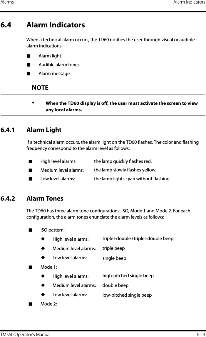
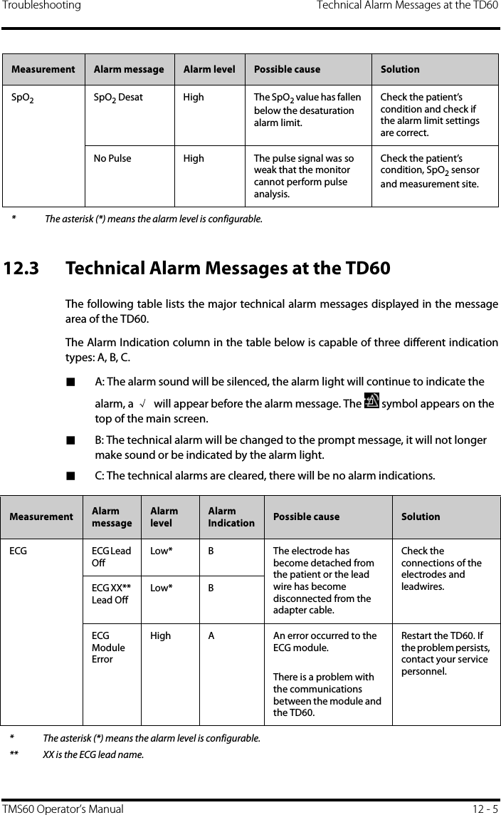
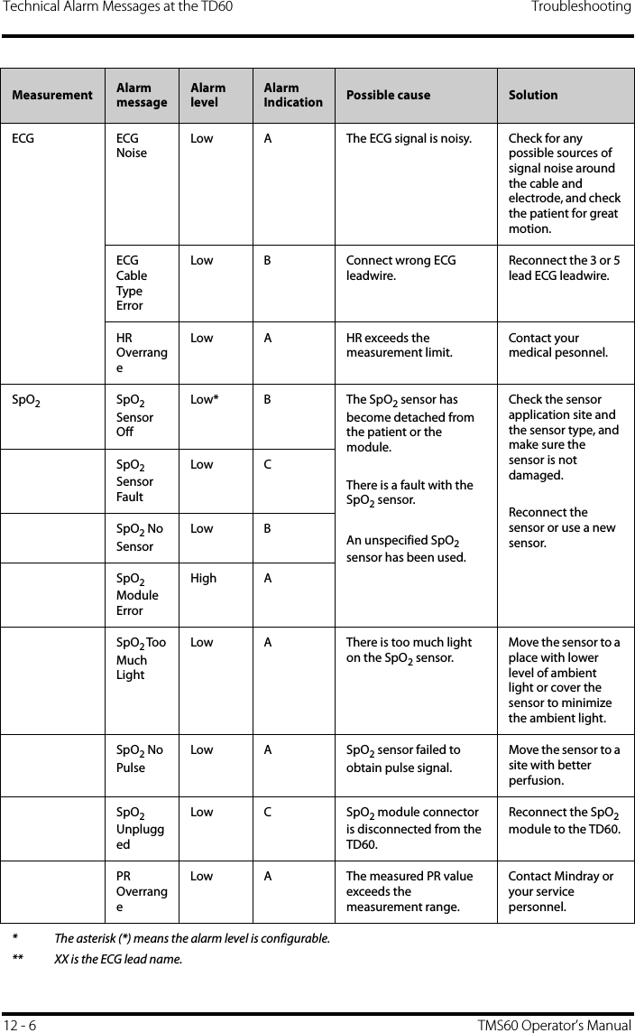
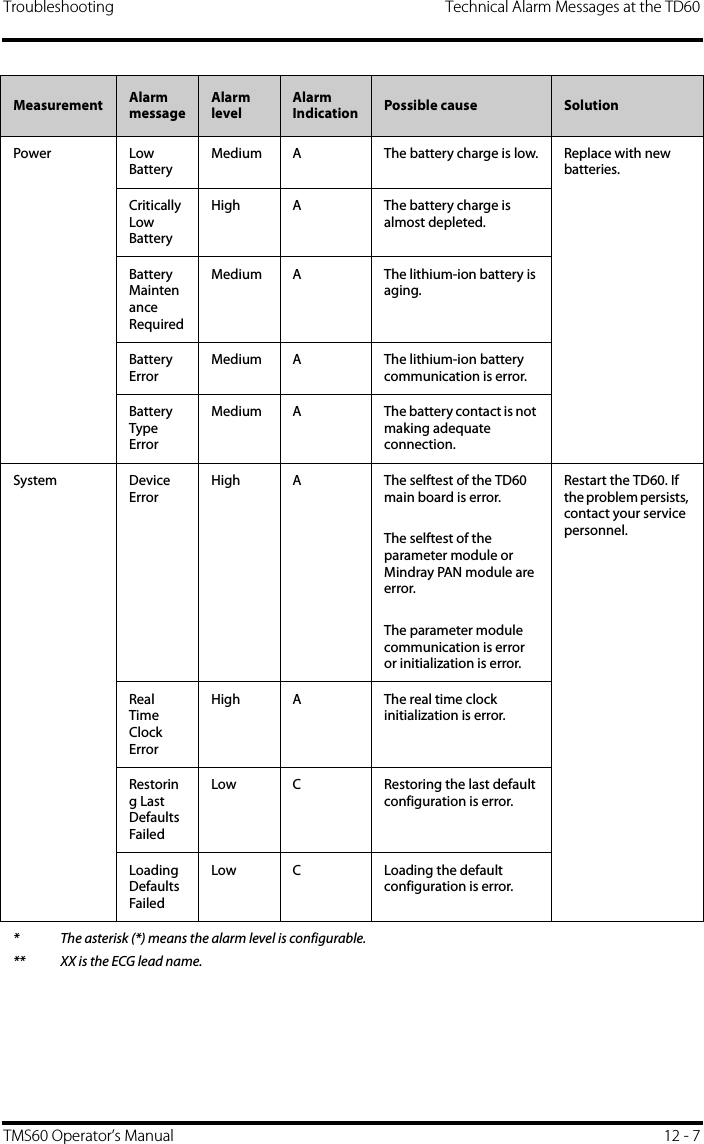
![Alarms Configuring the AlarmsTMS60 Operator’s Manual 6 - 56.5 Configuring the Alarms■For details on configuring the technical alarm volume, refer to "Configuring theAudio Volume" on page 4 - 5.■For details on configuring the TD60 technical alarm settings, refer to "Configuringthe Alarms Menu" on page 10 - 3.■For the CS alarm configurations, refer to the BeneVision Central Station Opera-tor’s Manual (P/N 046-007960-00).6.6 Resetting the AlarmsYou can acknowledge the on-going alarms by resetting the alarms. After being reset the alarm system can respond to a subsequent alarm condition.When a technical alarm occurs, follow this procedure to reset the TD60 alarm system.■Press the key to enter the main menu, and then tap [Alarm Reset] from the[Commands] section.OR1. Swipe your finger up at the bottom of the main screen to display the quick keys area.2. Tap the [Alarm Reset] quick key to reset the alarm system.When the alarm system is reset, depending upon the technical alarm there are several ways the alarm system may respond as follows:■The alarm sound will be silenced, the alarm light will continue to indicate thealarm, a √ will appear before the alarm message. The symbol appears on thetop of the main screen.■The technical alarm will be changed to the prompt message, it will not longermake sound or be indicated by the alarm light.■The technical alarms are cleared, there will be no alarm indications.For details about the indications of technical alarms when the alarm system is reset, refer to "Technical Alarm Messages at the TD60" on page 12 - 5.](https://usermanual.wiki/Mindray-BIO-Medical-electronics/TD608FE/User-Guide-2678251-Page-61.png)

![Monitoring ECG Preparation for Monitoring ECGTMS60 Operator’s Manual 7 - 97.3.5 Checking the Lead PlacementWith the Lead Placement function, you can check the lead status, information, and leadoff messages.7.3.5.1 Entering the Lead Placement MenuEnter the [Lead Placement] menu in either of the following ways:■Tap the lead fault message in the message area of the main screen.■In the main menu, tap [Lead Placement].7.3.5.2 Understanding the Lead Placement InstructionsThe [Lead Placement] window indicates the lead status.When any of the leads are off, the indications are as follows:■The lead off message displays on the information bar. The background color of the information bar corresponds to the alarm level.■A flashing circle indicates the disconnected lead.The color of the flashing circle is based on the alarm level.Example lead placement windowInformation barLead off indicator Lead on indicator](https://usermanual.wiki/Mindray-BIO-Medical-electronics/TD608FE/User-Guide-2678251-Page-71.png)
![Preparation for Monitoring ECG Monitoring ECG7 - 10 TMS60 Operator’s Manual7.3.6 Checking the Paced StatusIt is important to correctly set the patient’s paced status before you start monitoringECG. To check the paced status:■On the main screen, tap the HR digital area or ECG waveform area to enter the[ECG] menu.OR1. In the main menu, tap [Patient Info].2. In the [Pacer] field, check the setting of the paced status. The current paced status setting displays to the right of [Paced].3. If the paced status setting is not correct, tap [Paced] and select the correct paced status.■When [Paced] is set to [Yes ] at the TD60, and the pacer pulse is detected, the symbol displays in the waveform area of the CS screen, and the pace pulse markswill display on the ECG waveform both at the TD60 and CS.■When [Paced] is set to [No] at the TD60, and the pacer pulse is detected, the symbol displays in the waveform area of the CS screen.WARNING•For paced patients, you must set [Paced] to [Yes]. If it is incorrectly set to [No], the CS could mistake a pace pulse for a QRS and fail to alarm when the ECG signal is too weak. Do not rely entirely on rate meter alarms when monitoring patients with pacemakers. Always keep these patients under close surveillance.•The pacer pulses may be counted as QRS complexes, hence leading to wrong HR readings or failure to diagnose certain arrhythmia symptoms. Be sure to keep a close eye on patient’s with pacemaker devices.•For non-paced patients, you must set [Paced] to [No].•False low heart rate indicators or false asystole calls may result with cer-tain pacemakers because of pacemaker artifact such as electrical over-shoot of the pacemaker overlapping the true QRS complexes.•In order to minimize the possibility of interference, place electrodes, leadwires and TD60s as far away from the pacemaker as possible.](https://usermanual.wiki/Mindray-BIO-Medical-electronics/TD608FE/User-Guide-2678251-Page-72.png)
![Monitoring ECG Changing the ECG SettingsTMS60 Operator’s Manual 7 - 117.4 Changing the ECG SettingsYou can change the ECG settings from the ECG menu.7.4.1 Configuring the ECG SetupEnter the ECG menu in either of the following ways:■On the main screen, tap the HR digital area or ECG waveform area to enter the[ECG] menu.■In the main menu, tap [Parameter Setup] → [ECG] to enter the [ECG] menu.1. In the [Setup] section of the [ECG] menu, select the options described in the fol-lowing table.NOTE•When [Paced] is set to [Yes], the system does not detect PVC-related arrhythmia (including PVCs) resulting from pacemaker but still analyzes the normal QRS complex.Options Description Settings*Lead Placement Enters the [Lead Placement] window. Refer to "Checking the Lead Placement" on page 7 - 9 for details.Cable Type Selects the current ECG leadwire type. Auto, 3 Lead, 5 LeadRefer to "ECG Leadwire Types" on page 7 - 12 for details.Smart Lead (Monitored Lead)When [Cable Type] is set to [Auto], the option displays [Smart Lead]. Drag the swtich to right or left to enable or disable the Smart Lead function.When [Cable Type] is set to [3 Lead], the option displays [Monitored Lead].Refer to "ECG Leadwire Types" on page 7 - 12 for details.* The factory default settings are in bold.](https://usermanual.wiki/Mindray-BIO-Medical-electronics/TD608FE/User-Guide-2678251-Page-73.png)
![Changing the ECG Settings Monitoring ECG7 - 12 TMS60 Operator’s Manual2. Tap to exit the [ECG] menu.7.4.2 ECG Leadwire TypesECG leadwire type has three options as follows:■[Auto]: the device automatically sets the leadwire type according to the leadsetconnected.■[3 Lead]: the leadwire type is set to 3-lead. If the leadwire type is set to 3-lead, the [Smart Lead] option becomes [Monitored Lead]. You can select the desired lead from the [Monitored Lead] option to set the first ECG waveform displayed on the main screen.■[5 Lead]: the leadwire types is set to 5-lead.All waveform leads display on the main screen.7.4.3 Configuring the ECG Waveforms1. In the [Waveform] section of the [ECG] menu, select the options described in the following table.Filter Selects the ECG filter.MonitorUse under normal measurement conditions.STUse when ST monitoring is applied.Monitor, STColor Selects the ECG waveform color. 16 colorsThe default color is green.Options Description Settings** The factory default settings are in bold.Options Description Settings*All Lead Size Selects the waveform size for all the leads.To set the waveform size for a specific lead, select that lead from the [Waveform Size] section.1.25 mm/mV, 2.5 mm/mV, 5 mm/mV, 10 mm/mV, 20 mm/mV, 40 mm/mV, AutoThis configuration will be applied for all ECG waveform size.* The factory default settings are in bold.](https://usermanual.wiki/Mindray-BIO-Medical-electronics/TD608FE/User-Guide-2678251-Page-74.png)
![Monitoring ECG Changing the ECG SettingsTMS60 Operator’s Manual 7 - 132. Tap to exit the [ECG] menu.7.4.4 Configuring the Pacer1. In the [Pacer] section of the [ECG] menu, tap the options described in the follow-ing table.2. Tap to exit the [ECG] menu.Speed Selects the waveform sweep speed. 6.25 mm/s, 12.5 mm/s, 25 mm/sOptions Description Settings** The factory default settings are in bold.Options Description Settings*Paced Selects the paced status. Unspecified, No, Yes[Unspecified] is only available for the first time you set the paced sta-tus.Refer to "Checking the Paced Sta-tus" on page 7 - 10 for details.Markers Selects the pacer indicator.LineA 1 cm line shows above each ECG wave-form each time the pace pulse is detected.DotA 2 mm dot shows above each ECG wave-form each time the pace pulse is detected.Line, Dot, OffPacer Reject Selects whether or not to reject the pace pulses.On, Off* The factory default settings are in bold.NOTE•When [Paced] is set to [Yes], the [Markers] and [Pacer Rejection] options can be available.](https://usermanual.wiki/Mindray-BIO-Medical-electronics/TD608FE/User-Guide-2678251-Page-75.png)
![Understanding the ECG Display Monitoring ECG7 - 14 TMS60 Operator’s Manual7.4.5 Configuring the ECG Waveform SizeThe [Waveform Size] section of the [ECG] menu lists all available leads. You can selectthe desired ECG lead to set the waveform size. 7.5 Understanding the ECG Display7.5.1 HR Digital AreaThe HR digital area displays:1. Parameter name2. Measurement unit3. Heart rate value7.5.2 About the HR Digital Area■The HR area displays heart rate in the unit of bpm with a resolution of 1 bpm.■If the HR measurement is invalid, “- - -” displays in place of the HR value.■The HR value displays “0”, when the HR value is less than 15 bpm. 123](https://usermanual.wiki/Mindray-BIO-Medical-electronics/TD608FE/User-Guide-2678251-Page-76.png)

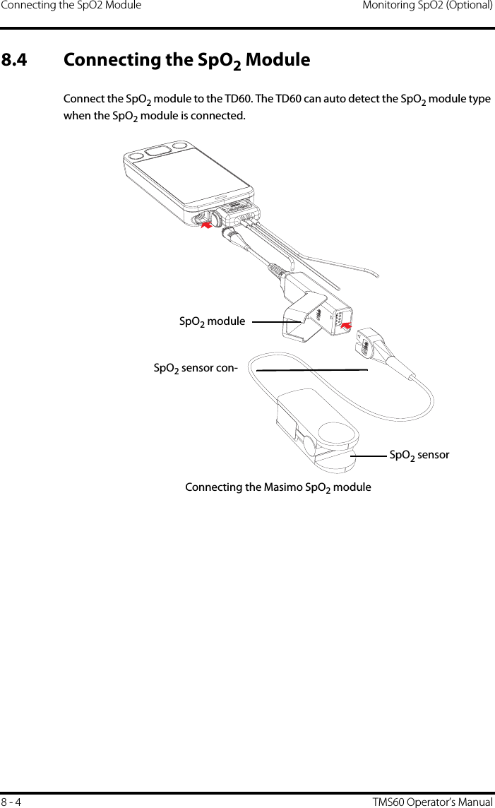
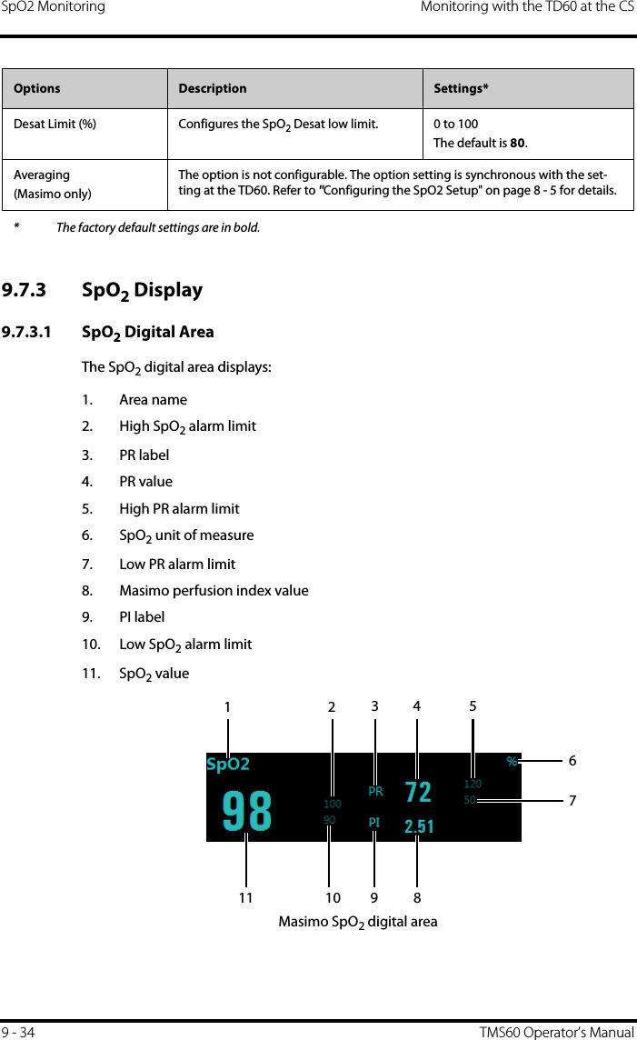
![Monitoring SpO2 (Optional) Changing the SpO2 SettingsTMS60 Operator’s Manual 8 - 5Connecting the Nonin SpO2 module8.5 Changing the SpO2 SettingsYou can change the SpO2 settings from the SpO2 menu.8.5.1 Configuring the SpO2 SetupEnter the SPO2 menu in either of the following ways:■On the main screen, tap the SpO2 digital area or SpO2 waveform area to enter the [SpO2] menu.■In the main menu, tap [Parameter Setup] → [SpO2] to enter the [SpO2] menu.1. In the [Setup] section of the [SpO2] menu, select the options described in the fol-lowing table.SpO2 moduleSpO2 sensorSpO2 sensor connector](https://usermanual.wiki/Mindray-BIO-Medical-electronics/TD608FE/User-Guide-2678251-Page-83.png)
![Monitoring SpO2 (Optional) Changing the SpO2 SettingsTMS60 Operator’s Manual 8 - 72. Tap to exit the [SpO2] menu.Averaging(Masimo only)The user-selectable averaging feature allows the clinician to select the desired level of visibility to subtle variations in the measured value. Depending on the patient acuity and area of care, shorter averaging times are sometimes preferred (sleep testing) over longer averaging times (telemetry) and vice-versa.8-second averaging is generally considered the most common averaging interval and recommended for most patients since it is short enough to provide visibility to subtle desaturations while also being long enough to minimize major changes in SpO2 due to quick, transitory desaturations. Although averaging times greater than 10 seconds are more likely to reduce visibility to rapid, brief desaturations, this may be desirable in care areas where brief desaturations that do not require clinician intervention occur more often (such as NICU). It is also recommended that this be enabled as a “sticky” configuration so as to hold the setting after power cycles.2-4 sec, 4-6 sec, 8 sec, 10 sec, 12 sec, 14 sec, 16 secFast SAT(Masimo only)Selects whether or not to enable FastSat. FastSat enables rapid tracking of arterial oxygen saturation changes as may be required in urgent situations.On, OffColor Selects the SpO2 waveform color. 16 colorsThe default color is cyan.Options Description Settings** The factory default settings are in bold.](https://usermanual.wiki/Mindray-BIO-Medical-electronics/TD608FE/User-Guide-2678251-Page-85.png)
![SpO2 Measurement Monitoring SpO2 (Optional)8 - 8 TMS60 Operator’s Manual8.5.2 Configuring the SpO2 Waveform1. In the [Waveform] field of the [SpO2] menu, select the options described in the following table.2. Tap to exit the [SpO2] menu.8.6 SpO2 Measurement8.6.1 Identifying SpO2 ModulesTo identify which SpO2 module you are using, see the company logo on the SpO2 module.■Masimo SpO2 module: white, with a logo of Masimo SET.■Nonin SpO2 module: blue, with a logo of Nonin.8.6.2 Applying the Sensor1. Select an appropriate sensor according to the module type, patient size, and weight.2. Remove colored nail polish from the application site.3. Apply the sensor to the patient.4. Connect the sensor to the SpO2 module and the SpO2 module to the TD60.The SpO2 measurement displays when the TD60 detects that a sensor is con-nected to the patient.Options Description Settings*Speed Selects the SpO2 pleth waveform speed. 6.25 mm/s, 12.5 mm/s, 25 mm/sDisplay SIQ(Masimo only)Selects whether or nor to show the Signal Indicator Quality (SIQ) in the SpO2 waveform area. The SIQ wave indicates the confidence associated with the saturation measurement and timing of the pulse. Higher pulse indicates a better signal.On, Off* The factory default settings are in bold.](https://usermanual.wiki/Mindray-BIO-Medical-electronics/TD608FE/User-Guide-2678251-Page-86.png)
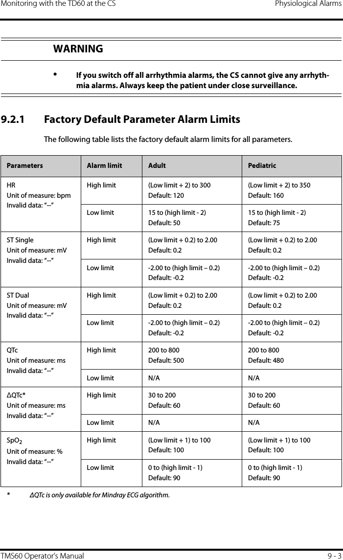
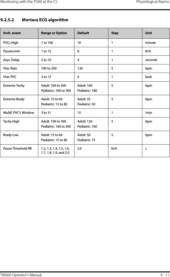
![Introduction Monitoring with the TD60 at the CS9 - 2 TMS60 Operator’s Manual9.1 IntroductionThe chapter describes the configurations and displays at the central station (CS) oncethe TD60 is connected to the CS.At the CS, Mindray ECG algorithm and Mortara ECG algorithm are available. You canselect either algorithm as required.9.2 Physiological AlarmsAt the CS, you can view and change the physiological alarm limits and alarm levels in the[Alarm Setup] menu. The [Alarm Setup] menu has three tabs: ■[Parameter Alarm Settings]: view and change the parameter alarm limits, alarmlevels and alarm responses.■[Arrhythmia Alarms]: view and change the arrhythmia alarms levels, and alarmresponses. ■[Arrh. Threshold Setup]: view and change the arrhythmia threshold settings forsome arrhythmia alarms.For details about the [Alarm Setup] menu, refer to the BeneVision Central StationOperator’s Manual (P/N 046-005011-00).WARNING•Be aware that the devices in your care area may each have different alarm settings to suit different patients. Always check that the alarm set-tings are appropriate for your patient before you start monitoring.•A potential hazard can exist if different alarm presets are used for the same or similar equipment in any single area, such as an intensive care unit or cardiac operating room.•Make sure that the alarm limits settings are appropriate for your patient before monitoring.•When monitoring patients that are not continuously attended by a clini-cal operator, properly configure the alarm system and adjust alarm set-tings as per the patient's condition.•Setting alarm limits to extreme values may cause the alarm system to become ineffective. For example, high oxygen levels may predispose a premature infant to retrolental fibroplasia. If this is a consideration do NOT set the high alarm limit to 100%, which is equivalent to switching the alarm off.](https://usermanual.wiki/Mindray-BIO-Medical-electronics/TD608FE/User-Guide-2678251-Page-92.png)
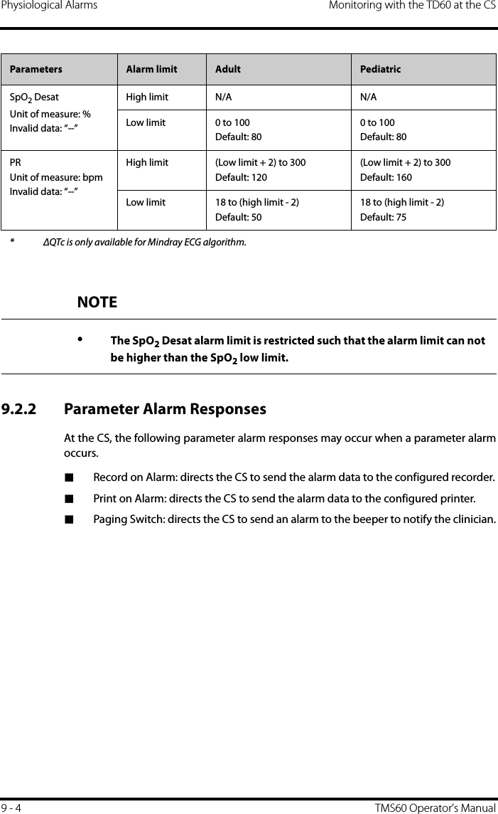
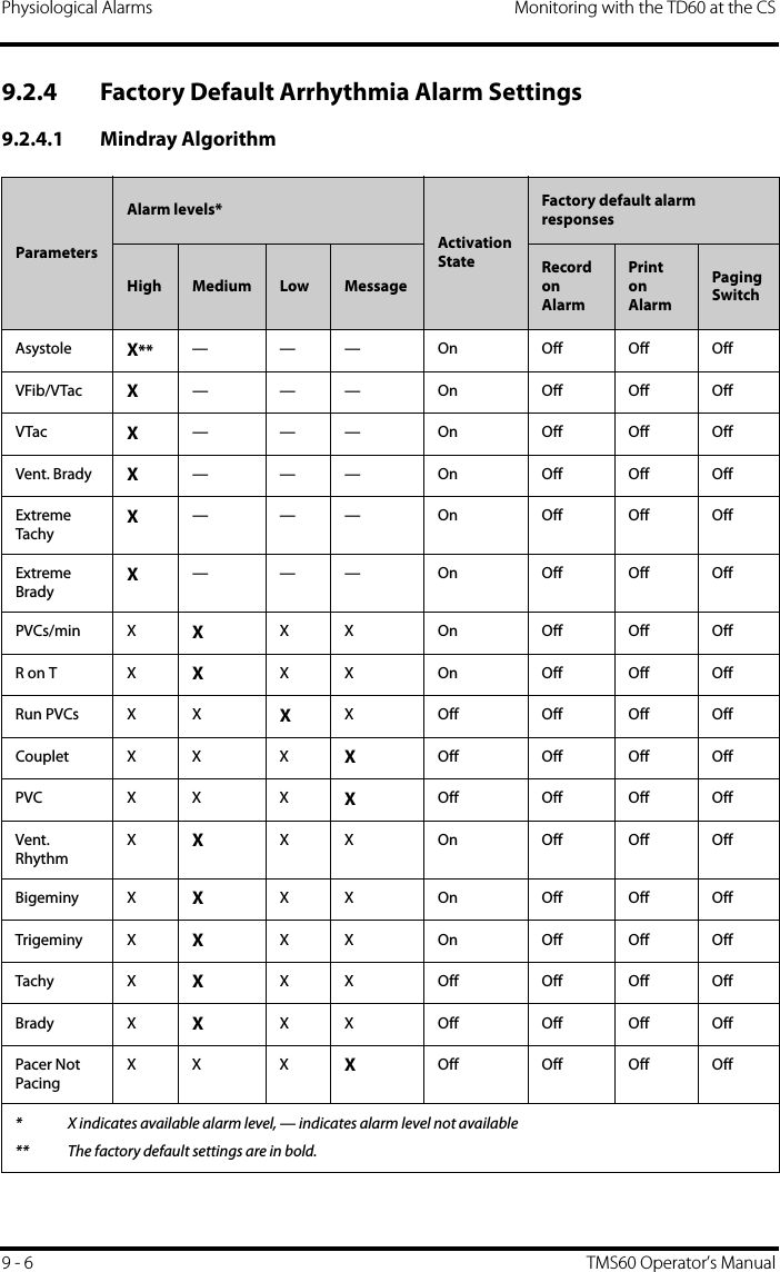
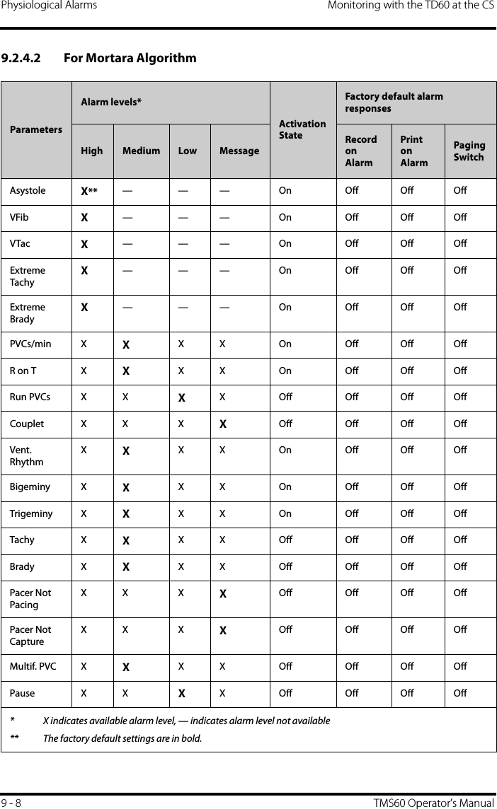
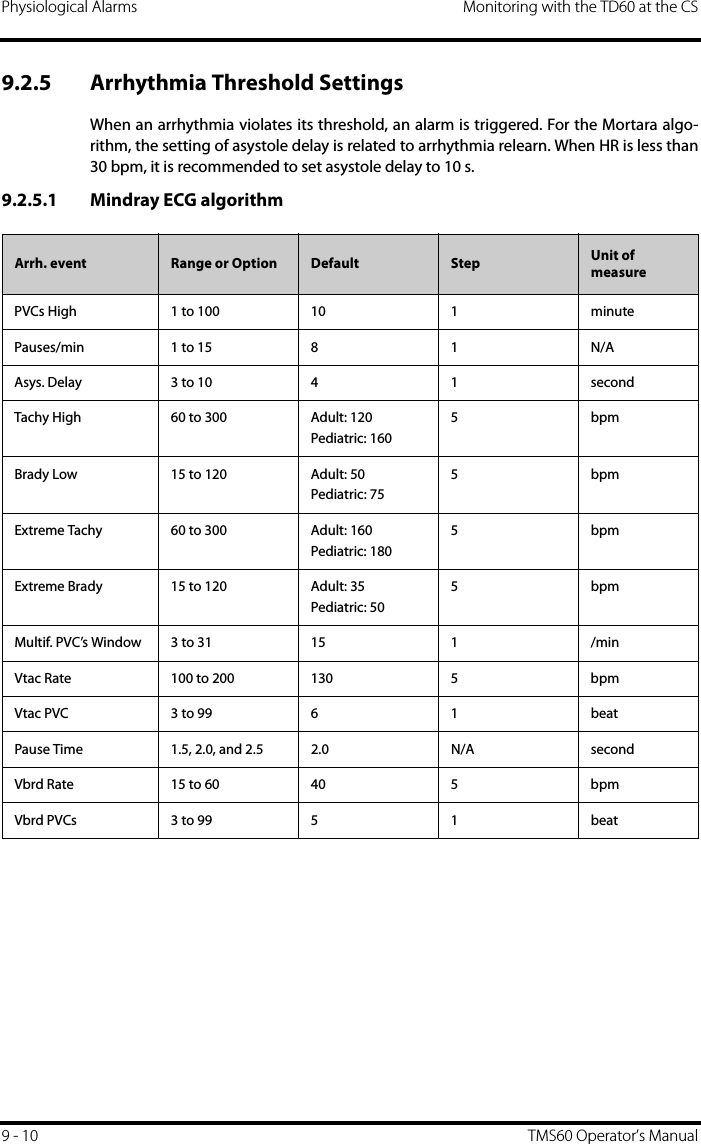
![Monitoring with the TD60 at the CS Physiological AlarmsTMS60 Operator’s Manual 9 - 59.2.3 Factory Default Parameter Alarm SettingsThe following table lists the factory default alarm levels and responses for all parameters. ParametersAlarm levels*Activation StateFactory default alarm responsesHigh Medium Low Record on AlarmPrint on AlarmPaging SwitchHR X X** — On Off Off OffST Single X XX Off Off Off OffST Dual X XX Off Off Off OffQTc X XX Off Off Off Off∆QTc*** X XX Off Off Off OffSpO2XX— On Off Off OffSpO2 Desat****X——On Off Off OffPR X X— On Off Off Off* X indicates available alarm level, — indicates alarm level not available** The factory default settings are in bold.*** ΔQTc is only available for Mindray ECG algorithm.**** The alarm level option for SpO2 Desat is not configurable. [High] is the only alarm level and cannot bechanged.](https://usermanual.wiki/Mindray-BIO-Medical-electronics/TD608FE/User-Guide-2678251-Page-95.png)
![Monitoring with the TD60 at the CS Physiological AlarmsTMS60 Operator’s Manual 9 - 7Pacer Not CaptureXX XXOff Off Off OffMissed Beat X X X XOff Off Off OffMultif. PVC X XX X Off Off Off OffNonsus. VtacXXX X On Off Off OffPause X X XX Off Off Off OffAFib X X X XOff Off Off OffIrr.Rhythm — — X XOff Off Off OffPauses/min X XX X On Off Off OffParametersAlarm levels*Activation StateFactory default alarm responsesHigh Medium Low MessageRecord on AlarmPrint on AlarmPaging Switch* X indicates available alarm level, — indicates alarm level not available** The factory default settings are in bold.NOTE•When [Paced] is set to [Yes], the Missed Beat (MIS) alarm is reported as the pacer not captured (PNC) or pacer not paced (PNP) alarm.](https://usermanual.wiki/Mindray-BIO-Medical-electronics/TD608FE/User-Guide-2678251-Page-97.png)
![Monitoring with the TD60 at the CS Physiological AlarmsTMS60 Operator’s Manual 9 - 9In addition, the activation state of some arrhythmias can be set as a whole with the fol-lowing buttons that are at the bottom of the [Arrhythmia Alarms] tab.Irr.Rhythm — — X XOff Off Off OffPauses/min X XX X On Off Off OffParametersAlarm levels*Activation StateFactory default alarm responsesHigh Medium Low MessageRecord on AlarmPrint on AlarmPaging Switch* X indicates available alarm level, — indicates alarm level not available** The factory default settings are in bold.NOTE•The priority of lethal arrhythmia alarms is always high. It is unchange-able.Button DescriptionLethals Only Sets the lethal arrhythmia alarms to on and all non-lethal arrhythmia alarms to off.All Alarm On Sets all arrhythmia alarms to on.All Alarm Off Sets all arrhythmia alarms to off.This button is enabled when the [Lethal Arrh. OFF] option in the [Telemetr y] tab from the [Admin Setup] menu is set to [Enable].](https://usermanual.wiki/Mindray-BIO-Medical-electronics/TD608FE/User-Guide-2678251-Page-99.png)
![ECG Monitoring Monitoring with the TD60 at the CS9 - 12 TMS60 Operator’s Manual9.3 ECG Monitoring At the CS, you can view and change the heart rate (HR), QT, ST, and arrhythmia settings inthe [ECG] tab of the [Parameter Setup] menu.For details about the [Parameter Setup] menu, refer to the BeneVision Central StationOperator’s Manual (P/N 046-005011-00).9.3.1 HR SettingsThe following table lists the HR settings in the [HR] section of the [ECG] tab.Options or Buttons Description Settings*HR Activation State Configures whether or not to enable the HR alarm.On, OffHR Alarm Priority Configures the HR alarm levels. High, MedHR High Limit (bpm) Configures the HR high alarm limit. Adult:(Low limit + 2) to 300The default is 120.Pediatric:(Low limit + 2) to 350The default is 160.HR Low Limit (bpm) Configures the HR low alarm limit. Adult:15 to (high limit - 2)The default is 50.Pediatric:15 to (high limit - 2)The default is 75.Pacer Rate (bpm) (only Mortara ECG algorithm)When some pacemaker pulses are difficult to reject, the pulses are counted as a QRS complex and could result in an incorrect HR and failure to detect some arrhythmias. Configures the pacemaker rate, the sys-tem can calculate HR and detect arrhyth-mias more accurately.40 to 100The default is 60.The option is unavailable when [Paced] is set to [No] at the TD60. For details about the paced status, refer to "Checking the Paced Status" on page 7 - 10.Sweep Speed Configures the ECG wave speed. 6.25 mm/s, 12.5 mm/s, 25 mm/s, 50 mm/sHR Source Configures the HR source. ECG, SpO2, Auto, Both* The factory default settings are in bold.](https://usermanual.wiki/Mindray-BIO-Medical-electronics/TD608FE/User-Guide-2678251-Page-102.png)
![Monitoring with the TD60 at the CS ECG MonitoringTMS60 Operator’s Manual 9 - 139.3.2 Waveform SetupThe ECG leads waveforms displayed in the waveform area are defined as the displayinglead.The CS uses information from two leads to detect beats and to compute HR. These twoleads are referred to as the primary and secondary leads. In addition, for Mortara ECGalgorithm, information from an additional lead (analysis lead) is made use of to classifythe beats (normal, abnormal etc). The user can select any of the available leads (depend-ing on whether a 3 or 5 lead cable is used) as primary, secondary or other analysis leads.For best results, the following guidelines should be used:■The QRS complex should be tall, narrow and preferably either completely above orbelow the baseline. If at all possible, avoid selecting a lead where the QRS complexis biphasic.■The P-waves and T-waves should be small compared to the QRS. They should beless than about 0.2 mV.9.3.2.1 Changing the Setting for Analysis Leads and Displaying LeadsThe default system setting for the analysis leads and displaying leads is [On], whichmeans that the analysis leads are consistent with the displaying leads. You can changethe default setting as following steps, if necessary. 1. At the CS, click [Admin Setup] → input the password → [OK].2. In the [Admin Setup] menu, click the [Telemetr y] tab.3. On the left side of the [Telemetry] tab, click [Analysis Lead Setting].The corresponding setting displays to the right of [Telemetr y].4. Set [Consistent with Displayed Lead] to [On] or [Off].◆[On]: the analysis lead is the same as the displaying lead.◆[Off]: the analysis lead is different from the displaying lead.HR Record on Alarm Select whether or not to activate the option to direct the CS to send the HR alarm data to the configured recorder.On, OffWaveform Setup Select to display the [Waveform Setup] menu.Refer to "Waveform Setup" on page 9 - 13 for details.Other Settings Select to display the [Other Settings] menu.Refer to "Other Settings" on page 9 - 15 for details.Options or Buttons Description Settings** The factory default settings are in bold.](https://usermanual.wiki/Mindray-BIO-Medical-electronics/TD608FE/User-Guide-2678251-Page-103.png)
![ECG Monitoring Monitoring with the TD60 at the CS9 - 14 TMS60 Operator’s Manual9.3.2.2 Changing ECG Wave SettingsIn the [Waveform Setup] menu, you can configure the displaying leads and analysisleads as desired. The lead settings are dependent on the setting of [Analysis Lead Set-ting].■When [Analysis Lead Setting] is set to [On], the ECG waveform configurations areapplied for the displaying leads and analysis leads. Follow the steps below to con-figure the ECG waveform setting:1. In the [HR] section of the [ECG] tab, click [Waveform Setup].The [Waveform Setup] menu displays.2. Select the options described in the following table to configure the ECG waveforms.3. Click [Exit] to save the settings and close the [Waveform Setup] menu.■When [Analysis Lead Setting] is set to [Off], the displaying leads and analysisleads should be configured respectively. Follow the steps below to configure theECG waveform setting:1. In the [HR] section of the [ECG] tab, click [Waveform Setup].The [Waveform Setup] menu displays.2. Select the options described in the following table to configure the ECG waveforms.Options DescriptionSettings*Lead Waveform sizeECG 1 Select the desired ECG lead and set the corresponding gain for ECG 1.I, II, III, aVR, aVL, aVF, V× 0.125, × 0.25, × 0.5, × 1, × 2, × 4ECG 2 Select the desired ECG lead and set the corresponding gain for ECG 2.I, II, III, aVR, aVL, aVF, V× 0.125, × 0.25, × 0.5, × 1, × 2, × 4ECG 3 Select the desired ECG lead and set the corresponding gain for ECG 3.I, II, III, aVR, aVL, aVF, V× 0.125, × 0.25, × 0.5, × 1, × 2, and × 4* The factory default settings are in bold.](https://usermanual.wiki/Mindray-BIO-Medical-electronics/TD608FE/User-Guide-2678251-Page-104.png)
![Monitoring with the TD60 at the CS ECG MonitoringTMS60 Operator’s Manual 9 - 153. Click [Exit] to save the settings and close the [Waveform Setup] menu.9.3.3 Other Settings The following table lists all settings in the [Other Settings] menu.Options DescriptionSettings*Lead Waveform sizeECG 1 Select the desired ECG lead and set the corresponding gain for ECG 1 to display in the waveform area.I, II, III, aVR, aVL, aVF, V× 0.125, × 0.25, × 0.5, × 1, × 2, × 4ECG 2 Select the desired ECG lead and set the corresponding gain for ECG 2 to display in the waveform area.I, II, III, aVR, aVL, aVF, V× 0.125, × 0.25, × 0.5, × 1, × 2, × 4ECG 3 Select the desired ECG lead and set the corresponding gain for ECG 3 to display in the waveform area.I, II, III, aVR, aVL, aVF, V× 0.125, × 0.25, × 0.5, × 1, × 2, × 4Primary lead Configures the primary analysis lead. I, II, III, aVR, aVL, aVF, VNoneSecondary lead Configures the secondary analysis lead. I, II, III, aVR, aVL, aVF, VNoneClassification lead (only for Mortara ECG algorithm)Configures other analysis lead. I, II, III, aVR, aVL, aVF, VNone* The factory default settings are in bold.Options Description Settings*Paced The option is unavailable at the CS. The paced status can be set at the TD60 only. Refer to "Checking the Paced Status" on page 7 - 10 for details.Pacer Reject Configures whether or not to reject the pace pulses.■[On]: the pace pulses are not countedas extra QRS complexes.■[Off]: the pace pulses are not rejected.On, OffThis [Pacer Reject] option is only available when [Paced] is set to [Yes ] at the TD60.* The factory default settings are in bold.](https://usermanual.wiki/Mindray-BIO-Medical-electronics/TD608FE/User-Guide-2678251-Page-105.png)
![ECG Monitoring Monitoring with the TD60 at the CS9 - 16 TMS60 Operator’s Manual9.3.4 ECG Display9.3.4.1 ECG Digital AreaThe ECG digital area displays:1. Area name2. HR value3. High HR alarm limit4. Low HR alarm limit5. Pauses threshold6. Pauses per minute value7. Pauses per minute label8. PVCs threshold9. PVCs per minute value10. PVCs per minute labelECG digital areaFilter Configures the ECG filter in all operating modes.■[Monitor]: use under normalmeasurement conditions.■[ST]: use when the ST monitoring isapplied.Monitor, STOptions Description Settings** The factory default settings are in bold.12345678910](https://usermanual.wiki/Mindray-BIO-Medical-electronics/TD608FE/User-Guide-2678251-Page-106.png)
![Monitoring with the TD60 at the CS ECG MonitoringTMS60 Operator’s Manual 9 - 179.3.4.2 ECG Waveform AreaThe ECG waveform area displays:1. ECG Lead2. ECG waveform size3. ECG filter setting4. Notch filter setting5. ECG waveform6. ECG scaleECG waveform areaNOTE•If the Activation State for HR, PVCs or Pauses alarm is set to [Off], the symbol displays to the right of corresponding parameter.1234 56](https://usermanual.wiki/Mindray-BIO-Medical-electronics/TD608FE/User-Guide-2678251-Page-107.png)
![QT Monitoring Monitoring with the TD60 at the CS9 - 18 TMS60 Operator’s Manual9.4 QT MonitoringA normal ECG waveform (as shown in the following figure) typically includes a sharp andwell defined QRS complexes with consistent spacing between R waves, and an ECGbaseline that is free of noise and artifact.A normal ECG waveform (for QT monitoring)The QT interval in an ECG lead is the time interval from the onset of the earliest deflec-tion in the QRS complex to the end of the T wave. QT monitoring can assist in the detec-tion of prolonged QT interval syndrome. 9.4.1 Measurement Limitations■At least one measured V-lead must be available in order for the algorithm toprocess QT.■QT/QTc values are calculated with 3-leadwire or 5-leadwire ECG cables.9.4.2 QT SettingsThe following table lists the QT settings in the [QT Analysis] section of the [ECG] tab.ST PointJ PointISO PointRTQT IntervalPQSOptions Description Settings*QT Analysis Enables or disables QT analysis. On, Off* The factory default settings are in bold.](https://usermanual.wiki/Mindray-BIO-Medical-electronics/TD608FE/User-Guide-2678251-Page-108.png)
![Monitoring with the TD60 at the CS QT MonitoringTMS60 Operator’s Manual 9 - 19QT Computational FormulaConfigures the QTc formula used.Bazett: Fridericia: Framingham: Hodges: QT Alarm Setup Configures the QT alarms. ■For details about the QT alarms limits, refer to "Factory Default Parameter Alarm Limits" on page 9 - 3 for details.■For details about the QT alarms responses, refer to "Factory Default Parameter Alarm Settings" on page 9 - 5 for details.■For Mindray algorithm, you can configure the QTc and ∆QTc alarm.■For Mortara algorithm, you can configure the QTc alarms.QT View Select to display the [QT View] menu.Refer to "QT View Menu (Only for Mindray ECG Algorithm)" on page 9 - 20 for details.This button is only available for the Mindray ECG algorithm.Options Description Settings** The factory default settings are in bold.QTc QT QTHR60-------------12/×=QTc QT QTHR60-------------13/×=QTc QT154 1 60QTHR-------------–×+=QTc QT1.75QTHR60–()×+=](https://usermanual.wiki/Mindray-BIO-Medical-electronics/TD608FE/User-Guide-2678251-Page-109.png)
![QT Monitoring Monitoring with the TD60 at the CS9 - 20 TMS60 Operator’s Manual9.4.3 QT View Menu (Only for Mindray ECG Algorithm)In the [QT View] menu, you can view a snapshot of the real-time wave and to verify thatthe QT algorithm detects correct Q and T points.The [QT View] menu displays, as shown in the following figure:◆The current waveform and parameter values display in green.◆The template waveform and parameter values display in yellow.◆The Q and T points are marked with a vertical line.◆The ∆QTc value is equal to the current QTc value minus the template QTcvalue.QT View menuUsing the buttons described in the following table as desired.Buttons Description Settings*Lead Select the desired lead to display on the [QT View] menu screen.II, I, III, aVR, aVL, aVF, VSet as Ref. Replaces the template waveform and QT/QTc values with the current waveform and QT/QTc values.NoneThe QT template updated time displays at the bottom of the screen.Print Prints the template and current wave-forms, and QT/QTc values for all leads.NoneExit Closes the [QT View] Menu. None* The factory default settings are in bold.](https://usermanual.wiki/Mindray-BIO-Medical-electronics/TD608FE/User-Guide-2678251-Page-110.png)
![Monitoring with the TD60 at the CS QT MonitoringTMS60 Operator’s Manual 9 - 219.4.4 QT DisplayWhen [QT Analysis] is enabled, the QT digital area displays:1. Area name2. QTc value3. High QTc alarm limit4. Activation State Off symbol for QTc alarm5. ∆QTc label6. ∆QTc value7. High ∆QTc alarm limit8. Activation State Off icon for ∆QTc alarm9. QT value10. QT label11. QTc label12. QT-HR label13. QT-HR valueExample QT digital area (for Mindray ECG algorithm)Example QT digital area (for Mortara algorithm)123456781011912 13](https://usermanual.wiki/Mindray-BIO-Medical-electronics/TD608FE/User-Guide-2678251-Page-111.png)
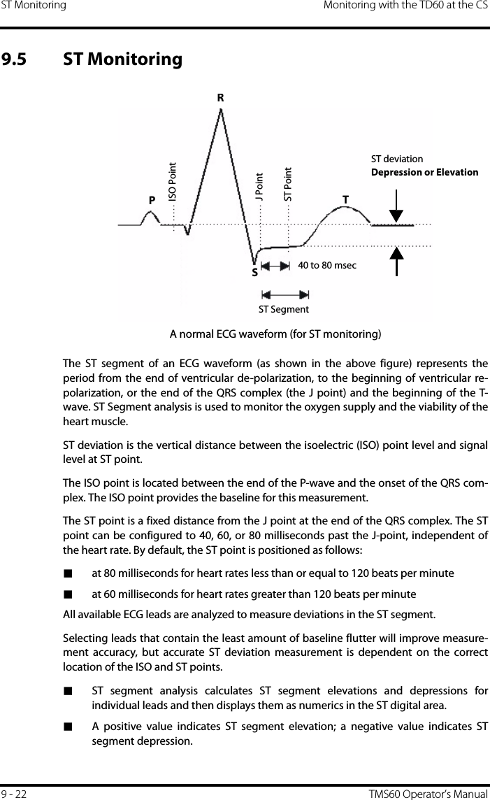
![Monitoring with the TD60 at the CS ST MonitoringTMS60 Operator’s Manual 9 - 239.5.1 Measurement Limitations■ST values may be affected by such factors as some drugs or metabolic andconduction disturbances.■Since ST is often calculated with a fixed delay from the J point, changes in heartrate may affect ST.■The ST algorithm has been tested for accuracy of the ST segment data. Thesignificance of the ST segment changes needs to be determined by a physician.9.5.2 ST SettingsThe following table lists the ST settings in the [ST Analysis] section of the [ECG] tab.WARNING•The ST algorithm has been tested for accuracy of the ST segment data. The significance of the ST segment changes need to be determined by a clinician.Options or Buttons Description Settings*ST Analysis Enables or disables ST analysis. On, OffIf [ST Analysis] is set to [On], the [Filter] option from the [Other Settings] menu is automatically set to [ST].Display ST Segments Select whether or not to display the ST segments in the waveform area.On, OffST Alarm Setup Configures the ST alarm settings. ■For details about the ST alarms limits, refer to "Factory Default Parameter Alarm Limits" on page 9 - 3 for details.■For details about the ST alarms responses, refer to "Factory Default Parameter Alarm Settings" on page 9 - 5 for details.Define ST Point Select to display the [Define ST Point] menu.Refer to "Adjusting ST Measure-ment Points" on page 9 - 24 for details.This button is only available when [ST Analysis] is set to [On].* The factory default settings are in bold.](https://usermanual.wiki/Mindray-BIO-Medical-electronics/TD608FE/User-Guide-2678251-Page-113.png)
![ST Monitoring Monitoring with the TD60 at the CS9 - 24 TMS60 Operator’s Manual9.5.3 Adjusting ST Measurement PointsThe ISO and ST points need to be adjusted when you start monitoring and if thepatient’s heart rate or ECG morphology changes significantly. Exceptional QRS com-plexes are not considered for ST-segment analysis.1. In the [ST Analysis] section of the [ECG] tab, click [Define ST Point].The [Define ST Point] menu displays, as shown in the following figure.Define ST point menu2. Adjust the parameter using the buttons described in the following table.WARNING•Always make sure that the ST measurement points are appropriate for your patient.Buttons Description Settings*Lead Select the desired ECG lead. I, II, III, aVR, aVL, aVF, VST (ms) Based on the ms setting selected, moves the ST point further or closer to the J point in the ST template.J+40, J+60, J+80, J+60/80* The factory default settings are in bold.](https://usermanual.wiki/Mindray-BIO-Medical-electronics/TD608FE/User-Guide-2678251-Page-114.png)
![Monitoring with the TD60 at the CS ST MonitoringTMS60 Operator’s Manual 9 - 253. Select the [OK] or [Cancel] button.◆The [OK] button saves the settings and closes the menu.◆The [Cancel] button closes the menu without saving the settings.9.5.4 ST DisplayWhen [ST Analysis] is enabled, the ST digital area displays:1. Area name 2. Activation State Off icon for ST alarm3. ST values4. Units of measure5. Lead identifierExample 5-lead ST digital areaISO/J Selecting [Auto] fixes the ISO and J/ST points.Selecting [Manual] allows the clinician to manually adjust ISO and J/ST points. Auto, ManualFor Mortara algorithm, the ISO and J/ST points can only be adjusted manually.ISO left arrow If [ISO/J] is set to manual, the button adjusts the ISO reference line to the left.ISO right arrow If [ISO/J] is set to manual, the button adjusts the ISO reference line to the right.J left arrow If [ISO/J] is set to manual, the button adjusts the J reference line to the left.J right arrow If [ISO/J] is set to manual, the button adjusts the J reference line to the right.Buttons Description Settings** The factory default settings are in bold.12453](https://usermanual.wiki/Mindray-BIO-Medical-electronics/TD608FE/User-Guide-2678251-Page-115.png)
![ST Monitoring Monitoring with the TD60 at the CS9 - 26 TMS60 Operator’s Manual9.5.5 ST Segment DisplayWhen [Display ST Segments] is enabled, the ST segments display in the waveform area:1. Lead identifier2. ST markers (ISO, J/ST)3. ST value4. ECG scale3-lead ST segment5-lead ST segments1234](https://usermanual.wiki/Mindray-BIO-Medical-electronics/TD608FE/User-Guide-2678251-Page-116.png)
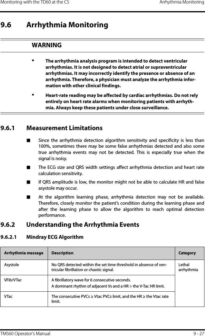
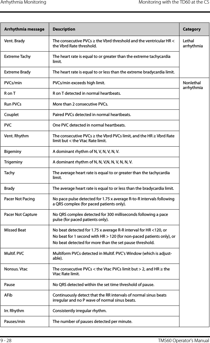
![Arrhythmia Monitoring Monitoring with the TD60 at the CS9 - 30 TMS60 Operator’s Manual9.6.3 Arrhythmia SettingsThe following table lists the arrhythmia settings in the [Arrhythmia Analysis] section ofthe [ECG] tab.9.6.4 RelearningA relearn can be done for arrhythmia, ST analysis, or for both simultaneously. The TD60 initiates the learning process for ST or Arrhythmia analysis after any of the fol-lowing:■TD60 power-up■Return to normal monitoring from the Standby mode■Enabling ST or Arrhythmia analysis■The lead has been changed in ECG 1 waveform (3 lead only)■Patient size changes■Selecting the Relearn button in the [Arrhythmia Analysis] sectionSelecting the Relearn button in the [Arrhythmia Analysis] section is recommendedafter one or more of the following:■ECG electrodes have been repositioned■Eight hours have passed since the last relearn■Significant changes occurred to the patient QRS complexOptions or Buttons Description Settings*Arrhythmia Alarms Configures the arrhythmia alarm settings. Refer to "Factory Default Arrhyth-mia Alarm Settings" on page 9 - 6 for details.Relearn Enables an arrhythmia relearning. Refer to "Relearning" on page 9 - 30 for details.QRS Threshold Settings Configures the QRS threshold. Refer to "Configuring the QRS Threshold" on page 9 - 31 for details.NOTE•ST Analysis must be turned on before it will relearn.](https://usermanual.wiki/Mindray-BIO-Medical-electronics/TD608FE/User-Guide-2678251-Page-120.png)
![Monitoring with the TD60 at the CS Arrhythmia MonitoringTMS60 Operator’s Manual 9 - 31■Significant changes occurred to the patient ECG rhythm■A clinician has observed clinically questionable arrhythmia calls■“Learning” occurred during a Leads Off condition9.6.5 Configuring the QRS ThresholdThe minimum detection threshold is approximately 0.16 mV. In case the P waves are verytall, one might consider moving the minimum QRS detection threshold up to be abovethe level of the P waves, so events like ventricular standstill are not missed.Two horizontal lines (one below and one above the baseline) appear on the screen.These represent the current minimum detection threshold on the positive and negativesides of the baseline so manual adjustment for both positive and negative going QRS'scan be made. Using the commands provided, move the minimum detection thresholdup or down to ensure it is above the level of the P waves but below the peak of the R-wave. Since the P-wave height could vary a little from beat to beat, do not set the hori-zontal line representing the minimum detection threshold at or barely above the level ofthe peak of the P wave. Ensure that it is at least one or two millimeters above the peak ofthe P wave but below the peak of the R-wave.1. In the [Arrhythmia Analysis] section of the [ECG] tab, click [Minimum QRS Threshold].The [Minimum QRS Threshold] menu displays, as shown in the following figure.CAUTION•Initiate ECG relearning only during periods of normal rhythm and when the ECG signal is relatively noise-free. If ECG learning takes place during ventricular rhythm, the ectopics may be incorrectly learned as the nor-mal QRS complex. This may result in missed detection of subsequent events of V-Tach and V-Fib.](https://usermanual.wiki/Mindray-BIO-Medical-electronics/TD608FE/User-Guide-2678251-Page-121.png)
![Arrhythmia Monitoring Monitoring with the TD60 at the CS9 - 32 TMS60 Operator’s ManualMinimum QRS Threshold menuThe current waveform displays the data of previous eight seconds. Use the buttons described in the following table as desired.2. Select the [OK] or [Cancel] button.◆Once the threshold is in the desired position, select the [OK] button to savethe settings and close the menu.◆To quit adjusting the threshold, select the [Cancel] button to close the menuwithout saving the settings.Buttons Description Settings*Gain Select the desired ECG waveform size. X1, X2, X4Refresh Displays the real-time waveform.Default Automatically sets the default threshold: 0.16 mV. or Manually adjust the minimum QRS detection threshold.Select the button to move the threshold line above the P wave, or select the button to move the threshold line down closer to the P wave.* The factory default settings are in bold.](https://usermanual.wiki/Mindray-BIO-Medical-electronics/TD608FE/User-Guide-2678251-Page-122.png)
![Monitoring with the TD60 at the CS SpO2 MonitoringTMS60 Operator’s Manual 9 - 339.7 SpO2 MonitoringAt the CS, you can view and change the SpO2 settings in the [SpO2] tab of the [Parame-ter Setup] menu.For details about the [Parameter Setup] menu, refer to the BeneVision Central StationOperator’s Manual (P/N 046-005011-00).9.7.1 Measurement LimitationsRefer to "Measurement Limitations" on page 8 - 2 for details.9.7.2 SpO2 SettingsThe following table lists the SpO2 settings in the [SpO2] tab.Options Description Settings*Activation State Configures whether or not to enable the SpO2 alarm.On, OffAlarm Priority Configures the SpO2 alarm levels. High, MedRecord on Alarm Selects whether or not to activate the recorder when an SpO2 alarm is triggered.On, OffSweep Speed Configures the SpO2 waveform sweep speed.6.25 mm/s, 12.5 mm/s, 25.0 mm/s, 50.0 mm/sDesat Limit Activation StateConfigures whether or not to enable the SpO2 Desat alarm.On, OffSensitivity(Masimo only)The option is not configurable. The option setting is synchronous with the set-ting at the TD60. Refer to "Configuring the SpO2 Setup" on page 8 - 5.SpO2 High Limit (%) Configures the SpO2 high alarm limit. (Low limit + 1) to 100The default is 100.SpO2 Low Limit (%) Configures the SpO2 low alarm limit. 0 to (high limit - 1)The default is 90.PR High Limit (bpm) Configures the PR high alarm limit. (Low limit + 2) to 300The default for adult is 120.The default for pediatric is 160.PR Low Limit (bpm) Configures the PR low alarm limit. 18 to (high limit - 2)The default for adult is 50.The default for pediatric is 75.* The factory default settings are in bold.](https://usermanual.wiki/Mindray-BIO-Medical-electronics/TD608FE/User-Guide-2678251-Page-123.png)
![Monitoring with the TD60 at the CS SpO2 MonitoringTMS60 Operator’s Manual 9 - 35Nonin SpO2 digital area9.7.3.2 SpO2 Waveform AreaThe SpO2 waveform area displays:1. Area name2. Pleth waveformSpO2 waveform areaNOTE•When [HR Source] of the [ECG] tab is set to [Both], the PR value displays on the SpO2 digital area.12](https://usermanual.wiki/Mindray-BIO-Medical-electronics/TD608FE/User-Guide-2678251-Page-125.png)


![Introduction Configuring the TD6010 - 2 TMS60 Operator’s Manual10.1 IntroductionThis TD60 Maintenance menu provides access to the system settings such as location,device name, alarm settings, quick keys, screen lock, and password updates. Enteringthis menu requires a password.10.2 Maintenance MenuThe [Maintenance] menu contains the following submenus:■General■Alarms■Quick Keys■Defaults■Screen Lock■Edit Passcodes■Device Name■Demo Mode■Service10.2.1 Entering the Maintenance menu1. In the main menu, tap [Maintenance].2. Input the maintenance password.3. Tap [Accept] to enter the [Maintenance] menu.10.2.2 Configuring the General MenuSelect [General] to configure the display auto off, language, location, notch filter, ECGlead labeling, SpO2 module, SpO2 tone, and enable or disable ECG calibration.1. In the [Maintenance] menu, tap [General].The current setting displays to the right of the option.2. Select the options described in the following table.Options Description Settings*Display Auto Off Configures the time for display auto off. 1 min, 2 min, 5 min, 15 min 30 min, OffLanguage Configures the system language. ENGLISH, FRENCH* The factory default settings are in bold.](https://usermanual.wiki/Mindray-BIO-Medical-electronics/TD608FE/User-Guide-2678251-Page-128.png)
![Configuring the TD60 Maintenance MenuTMS60 Operator’s Manual 10 - 33. Tap to exit the [General] menu.10.2.3 Configuring the Alarms MenuSelect [Alarms] to configure the alarm tone, reminder tone, reminder interval, minimumalarm volume, and technical alarm priority.1. In the [Maintenance] menu, tap [Alarms].The current setting displays to the right of the option.2. Select the options described in the following table.Location Changes the hospital and department names.N/ANotch Filter Configures the ECG Notch filter. This option is used to filter out AC line noise from the ECG waveform.50 Hz, 60 Hz, OffThe default is 50 Hz when the device is not configured for the US.ECG Lead Labeling Changes the ECG lead labeling. AHA, IECCalibrate ECG Enables or disables the ECG verification. On, OffRefer to "Verifying the ECG at the TD60" on page 14 - 4 for details.SpO2 Module Changes the SpO2 module. Masimo, NoninSpO2 Tone Configures the SpO2 tone. Mode 1, Mode 2Options Description Settings** The factory default settings are in bold.NOTE•Mindray recommends the same SpO2 tone mode be used for the devicewithin a monitoring area.Section & Options Description Settings*SoundsStyle Allows an authorized user to set the alarm tone pattern.ISO, Mode 1, Mode 2* The factory default settings are in bold.](https://usermanual.wiki/Mindray-BIO-Medical-electronics/TD608FE/User-Guide-2678251-Page-129.png)
![Maintenance Menu Configuring the TD6010 - 4 TMS60 Operator’s Manual3. Tap to exit the [Alarms] menu.TimeoutReminder Tone Allows an authorized user to enable or disable the reminder tone.If the alarm tone is turned off, enabling this set-ting can issue a periodic reminder tone. On, OffReminder Interval Allows an authorized user to configure the intervals between the alarm tones.1 min, 2 min, 3 min, 5 min, 10 minMinimum Alarm VolumeTechnical Allows an authorized user to set the minimum technical alarm volume.The minimum technical alarm volume defines the minimum value you can set for the techni-cal alarm volume.For example:If the minimum technical alarm volume is set to 5, the minimum value you can set for the tech-nical alarm volume in the [Audio Volume] menu is 5 (as shown in the following figure).If the minimum technical alarm volume is set to Off, and the technical alarm volume can be set to 0, the alarm sound is turned off and the symbol appears on the screen.Off, 1, 2, 3, 4, 5, 6, 7, 8, 9, 10Technical Alarm PriorityECG Lead Off Allows an authorized user to configure the alarm level.Low, Medium, HighSpO2 Sensor Off Allows an authorized user to configure the alarm level.Low, Medium, HighSection & Options Description Settings** The factory default settings are in bold.Minimum value](https://usermanual.wiki/Mindray-BIO-Medical-electronics/TD608FE/User-Guide-2678251-Page-130.png)
![Configuring the TD60 Maintenance MenuTMS60 Operator’s Manual 10 - 510.2.4 Quick Keys Menu10.2.4.1 Changing the Quick Keys1. In the [Maintenance] menu, tap [Quick Keys].The [Quick Keys] configuration menu displays.2. From the quick keys area at the bottom of the screen, tap a quick key you want to configure.A list of option displays. WARNING•When the technical alarm audio volume is set to alarm sound and thealarm sound is turned off, the TD60 will not enunciate technical alarmswhen they occur. Be careful when turning off the alarm volume.•Do not rely exclusively on the audible alarm system for monitoring.Adjustment of alarm volume to a low level may result in a hazard to thepatient. Always keep the patient under close surveillance.](https://usermanual.wiki/Mindray-BIO-Medical-electronics/TD608FE/User-Guide-2678251-Page-131.png)
![Maintenance Menu Configuring the TD6010 - 6 TMS60 Operator’s Manual3. Tap the desired option from the list of options to configure the selected quick key.4. Repeat steps 2 to 3 to configure other quick keys, if needed.5. Tap to exit the [Quick Keys] menu.10.2.4.2 Deleting a Quick Key1. From the quick keys area at the bottom of the [Quick Keys] menu, press and hold the desired quick key for two seconds, and then release it.The quick key background turns to red and displays [Delete].2. Tap [Delete].The quick key is removed from the quick keys area, and the area displays [Not Used].3. Tap to exit the [Quick Keys] menu.10.2.5 Configuring the Defaults MenuThe [Defaults] menu allows an authorized user to manage the system configurations.1. In the [Maintenance] menu, tap [Defaults].2. Select the options described in the following table.A list of optionsOptions DescriptionSave Departmental Defaults Allows an authorized user to save the current device settings for the selected patient category.Export Device Settings Copies the user configuration to the external device.](https://usermanual.wiki/Mindray-BIO-Medical-electronics/TD608FE/User-Guide-2678251-Page-132.png)
![Configuring the TD60 Maintenance MenuTMS60 Operator’s Manual 10 - 73. Tap to exit the [Defaults] menu.10.2.6 Transferring a ConfigurationThe TD60 is capable of configuring multiple devices through one export operation via awireless interface.To transfer the configuration from the TD60 unit to an external device:1. In the [Maintenance] menu of an external device, tap [Defaults] → [Import Device Settings] to enter the settings import mode.2. In the [Maintenance] menu of the TD60 unit, tap [Defaults] → [Export Device Settings] to enter the [Export Device Settings] menu.The discovered external devices are listed in the [Export Device Settings] menu.3. Select the desired external devices by tapping the check box.4. Tap [Export] to start exporting the TD60 unit configuration.The selected external devices screen will shortly display the “Downloading device settings” message.■On the external devices if an import is successful, the external device will displaythe “Download complete.” message, and after 10 seconds return to the [Defaults]menu. On the TD60 unit, the status for the external device will display the“Complete” message.■On the external device if the import fails, the external device will display the“Import attempt failed.” message. On the TD60 unit, the status for the failedexternal device will display the “Failure” message and remain in the list. The user has two options when a failure occurs:◆To stop the import from the external device, tap the icon to exit the[Import Device Settings].Import Device Settings Copies the settings from the external device to theTD60 unit. Refer to "Trans-ferring a Configuration" on page 10 - 7 for details.Restore Factory Defaults Allows an authorized user to reestablish the original database power up settings to factory default values.Options DescriptionWARNING•Do not power off the devices during the download process.](https://usermanual.wiki/Mindray-BIO-Medical-electronics/TD608FE/User-Guide-2678251-Page-133.png)
![Maintenance Menu Configuring the TD6010 - 8 TMS60 Operator’s Manual◆To retry the import from the TD60 unit, tap the external device which is dis-playing the [Failure] message, tap the [Retry] button to restart the transfer.You may need to repeat the retry operation several times until the transfer issuccessful.10.2.7 Screen Lock Menu10.2.7.1 Understanding the Screen Lock ModeThere are two modes of being able to lock the screen to assist in preventing unauthor-ized use. Each mode allows the user access to certain features of the product withoutentering a passcode. When the correct passcode is entered, all features are available.■Locked Mode Features:◆Main screen and main menu are not accessible without passcode entry.◆The message area is still viewable.◆Hardkeys are enabled.■View Only Features:◆Upon powering up, the main screen will be displayed after the new patientchoice is made.◆Main Screen is accessible without passcode entry.◆The [System Info] menu is accessible by tapping the battery symbol on themain screen.◆The [Lead Placement] menu is accessible by tapping an “ECG Lead Off”message in the message area.◆Ability to change display orientation.◆Hardkeys are enabled.10.2.7.2 Setting the Screen LockThe initial enabling of screen lock mode requires a passcode to be entered immediatelyas follows:1. In the [Maintenance] menu, tap [Screen Lock] to select a screen lock mode.2. Enter a new passcode for the screen lock.After the passcode is entered, the screen exits the passcode setup menu. The selected lock mode displays to the right of [Screen Lock].](https://usermanual.wiki/Mindray-BIO-Medical-electronics/TD608FE/User-Guide-2678251-Page-134.png)
![Configuring the TD60 Maintenance MenuTMS60 Operator’s Manual 10 - 910.2.7.3 Changing the Current Screen Lock Passcode1. In the [Maintenance] menu, tap [Screen Lock].2. Tap [Screen Lock Passcode].3. Input the current password.4. Input and verify the new password10.2.8 Changing the Passwords1. In the [Maintenance] menu, tap [Edit Passwords].◆Tap [Maintenance Password] and follow the on-screen instructions tochange the maintenance password.◆Tap [Service Password] and follow the on-screen instructions to change theservice password.2. Tap the icon to exit the [Edit Passwords] menu.10.2.9 Changing the Device Name1. In the [Maintenance] menu, tap [Device Name].2. Use the on-screen keyboard to input the device name.3. Tap [Accept] to save the setting and exit the [Device Name] menu.10.2.10 Demo ModeAllows an authorized user to choose a demonstration mode for in-servicing staff or test-ing product features. 10.2.11 Service MenuAllows an authorized user access to the passcode protected Service menu.NOTE•Do not set the same device name for the TD60s.](https://usermanual.wiki/Mindray-BIO-Medical-electronics/TD608FE/User-Guide-2678251-Page-135.png)


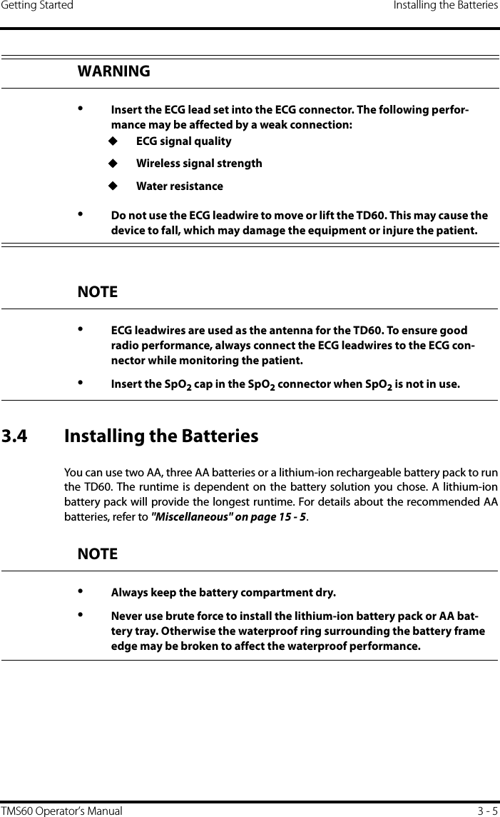
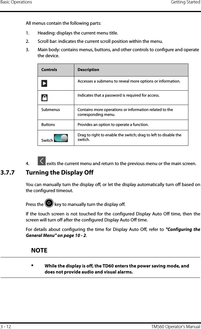
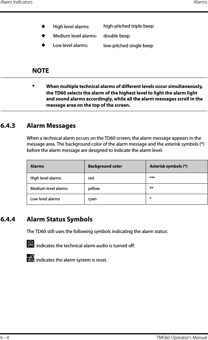
![Maintenance and Testing Schedule Maintenance14 - 4 TMS60 Operator’s Manual14.4 Maintenance and Testing ScheduleThe following maintenance and tests, except for visual inspection, power on test, andbattery check, shall be carried out by the service personnel only. Contact your servicepersonnel if any maintenance is required. Make sure to clean and disinfect the equip-ment before any test and maintenance.14.5 Checking the System InformationTo view the information about the device, radio frequency (RF), battery, MPAN, and sys-tem statistics, you can go to the main menu → [System Info].14.6 Verifying the ECG at the TD60The ECG signal may be inaccurate due to hardware or software problems. As a result, theECG wave amplitude becomes greater or smaller. To verify the ECG waveform amplitude: 1. In the main menu, tap [Maintenance].2. Input the maintenance passcode.3. Tap [Accept].4. In the [Maintenance] menu, tap [Others].5. Enable [Calibrate ECG].A square wave appears on the screen and the message [ECG Calibrating] is dis-played.Check/Maintenance Item Recommended FrequencyVisual inspection When first installed or reinstalled. ECG test and verification Performance test 1. If the user suspects that the measurement is incorrect.2. Following any repairs or replacement of rele-vant module.3. Once every two years.VerificationSpO2 testPower on test 1. When first installed or reinstalled.2. Following any maintenance or the replace-ment of any main unit parts.Battery check Functionality test 1. When first installed.2. Whenever the battery is replaced.Performance test When the battery run time reduced significantly.](https://usermanual.wiki/Mindray-BIO-Medical-electronics/TD608FE/User-Guide-2678251-Page-162.png)
![Maintenance Verifying the ECG at the TD60TMS60 Operator’s Manual 14 - 56. Compare the amplitude of the square wave with the wave scale. The difference should be within 5%.7. After completing the verification, disable [Calibrate ECG].](https://usermanual.wiki/Mindray-BIO-Medical-electronics/TD608FE/User-Guide-2678251-Page-163.png)


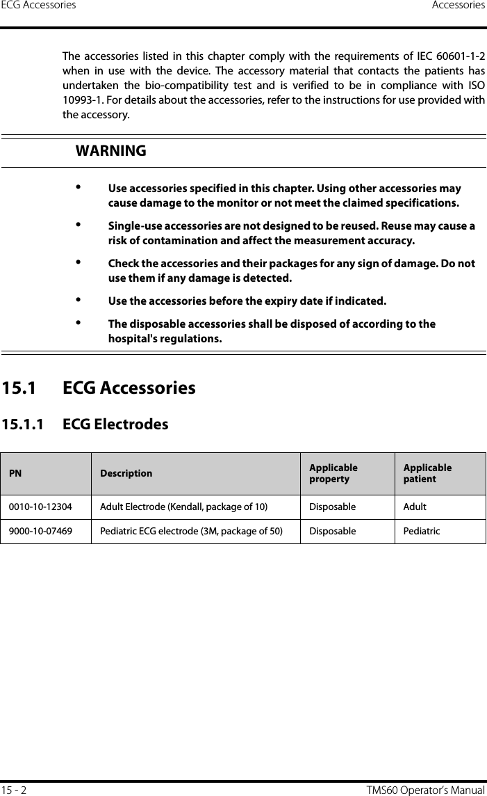
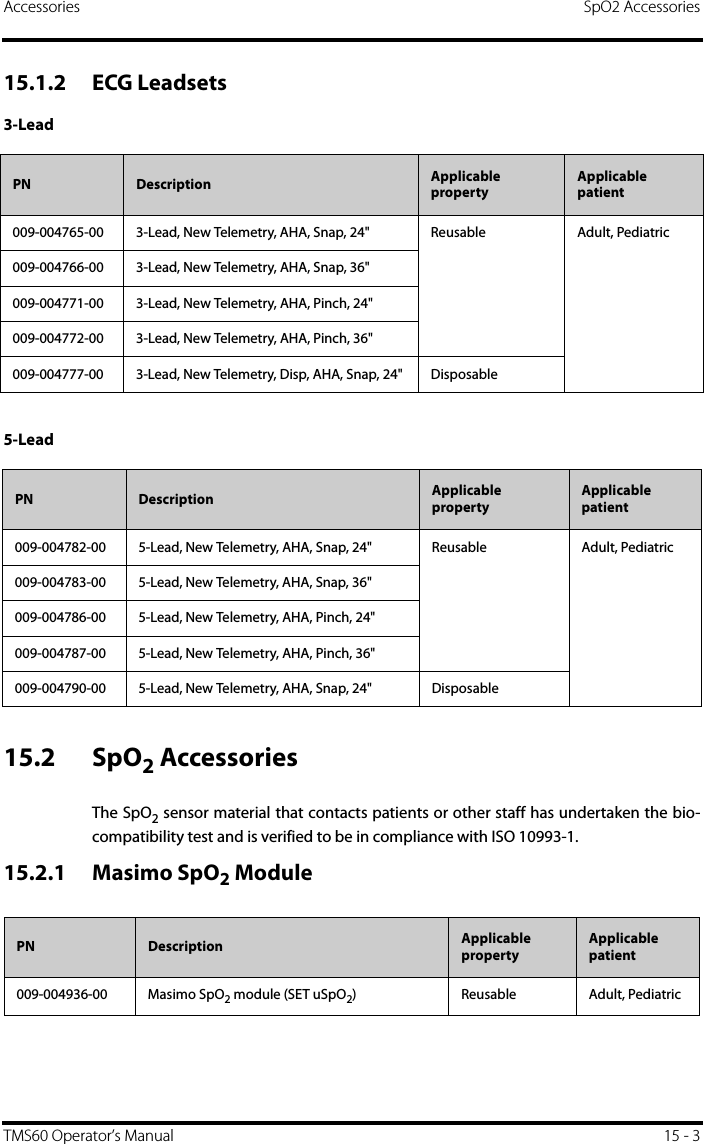
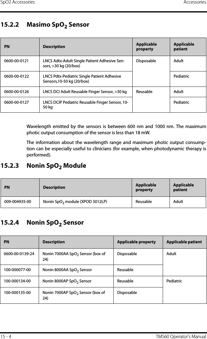
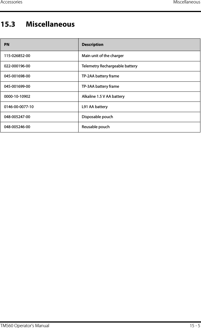

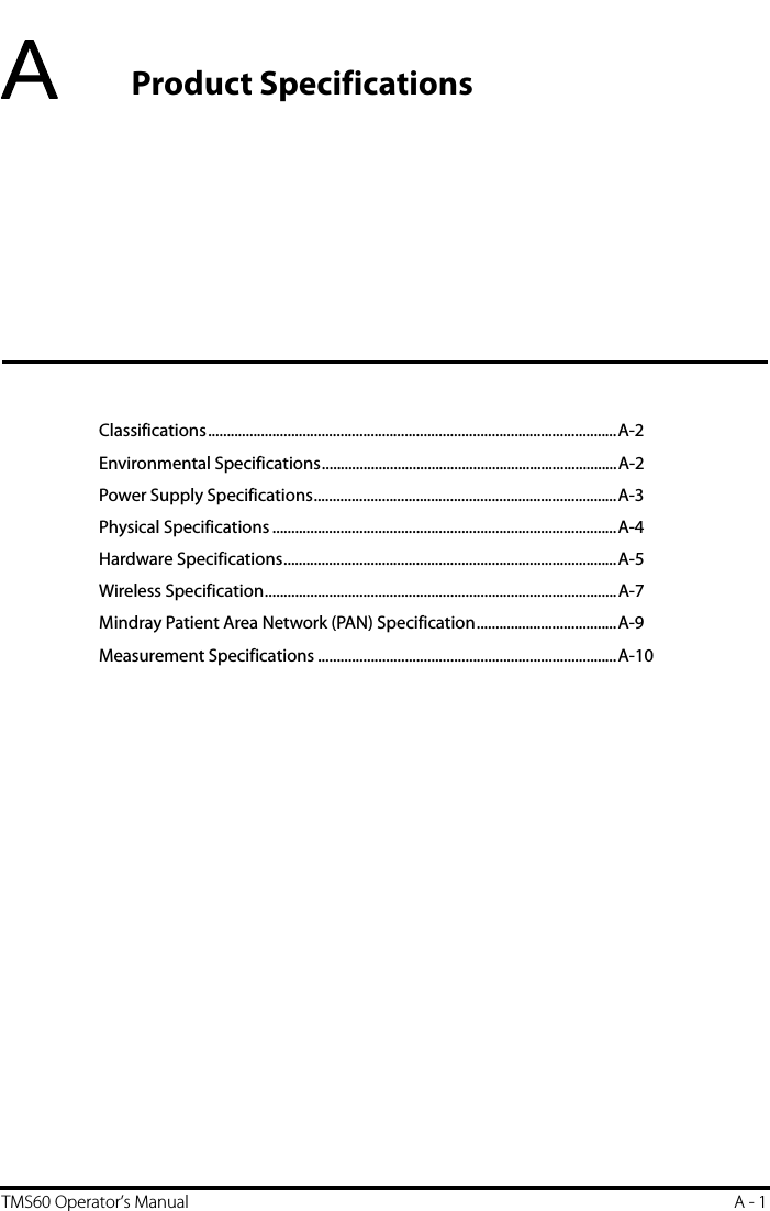
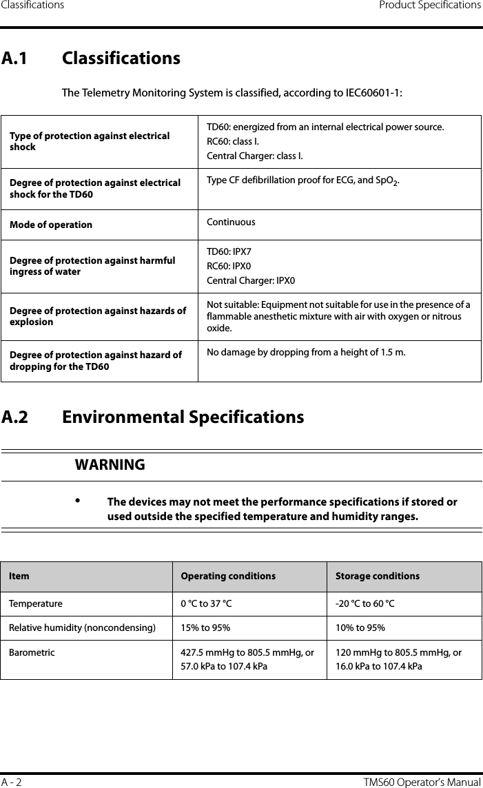
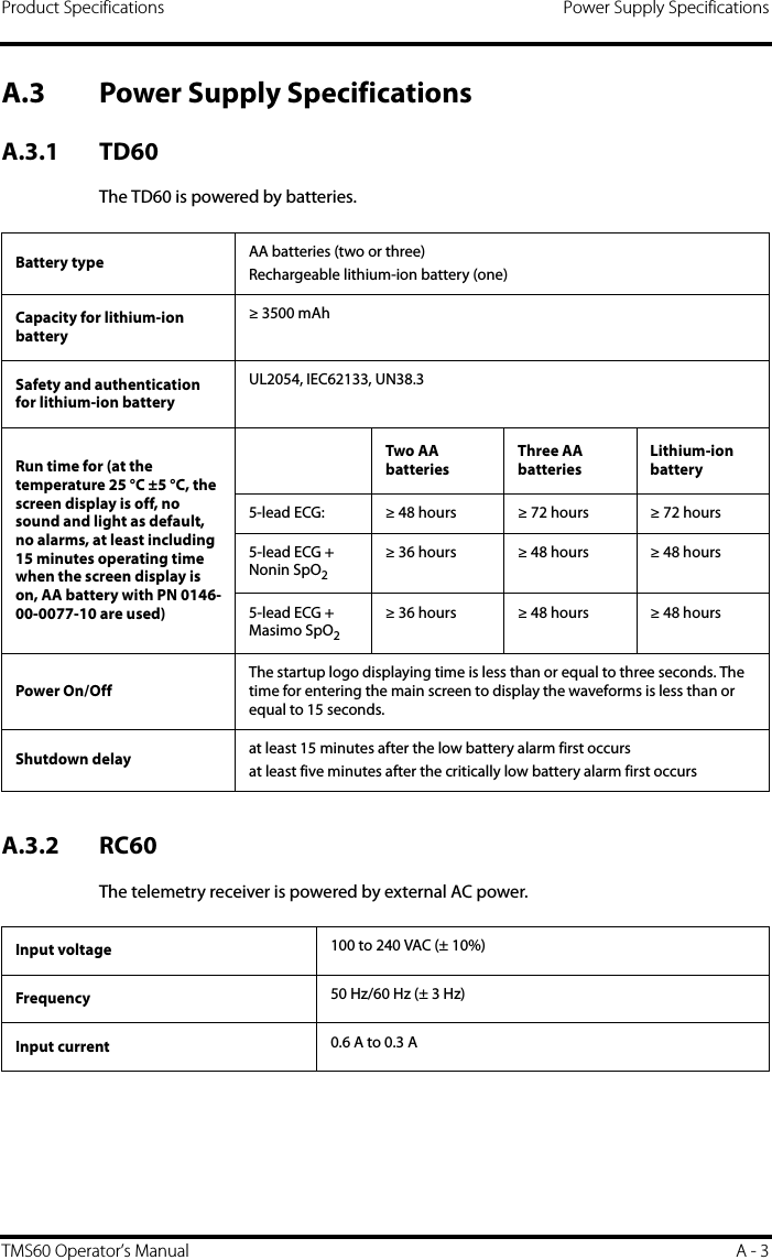
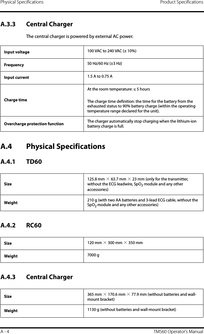
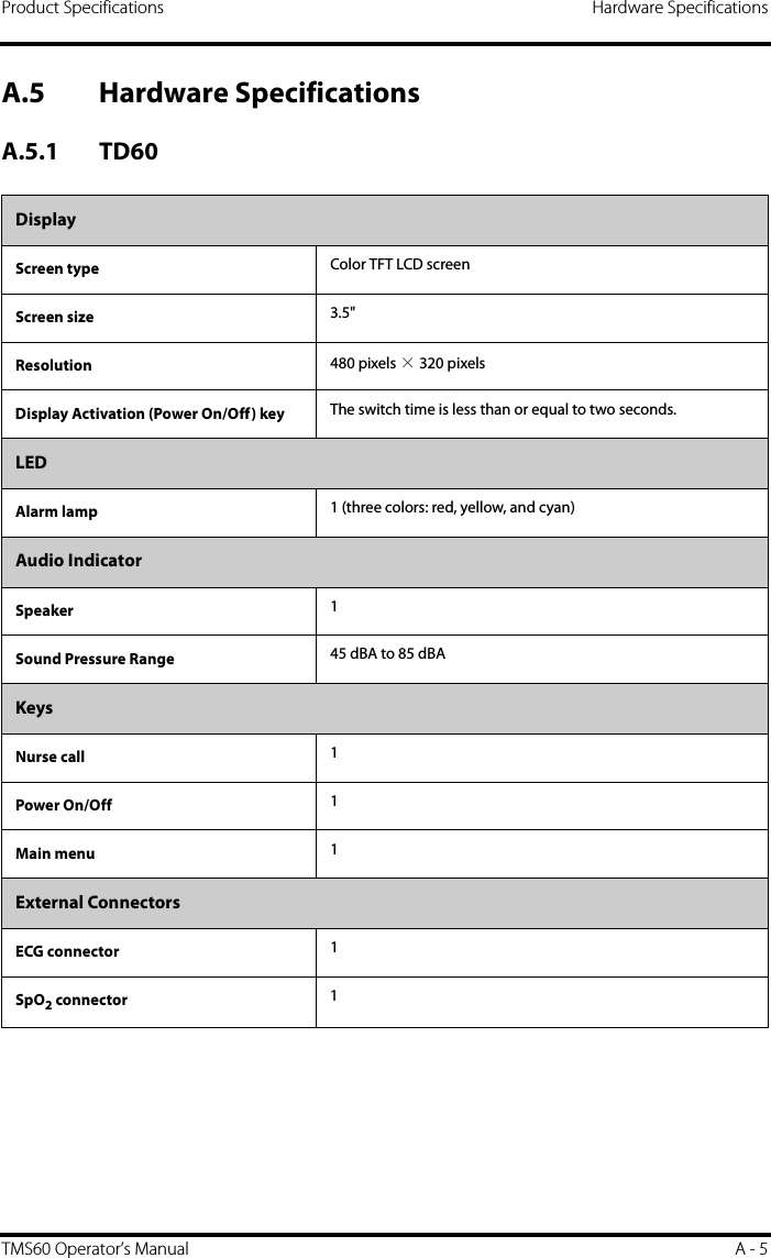
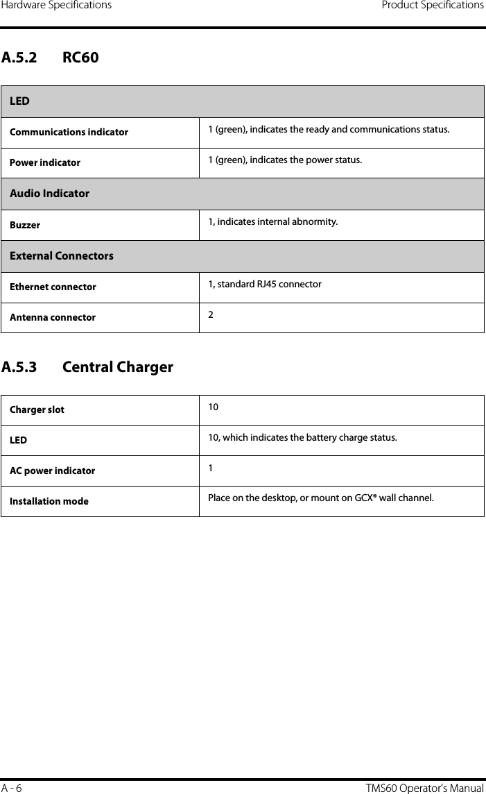
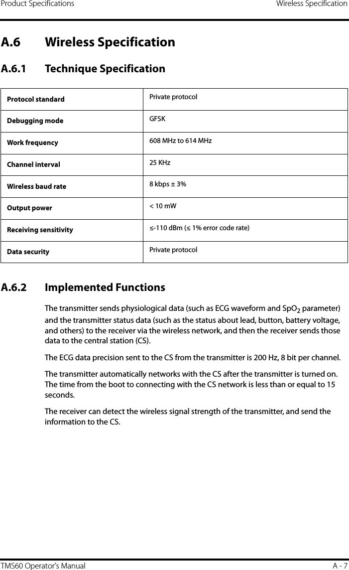
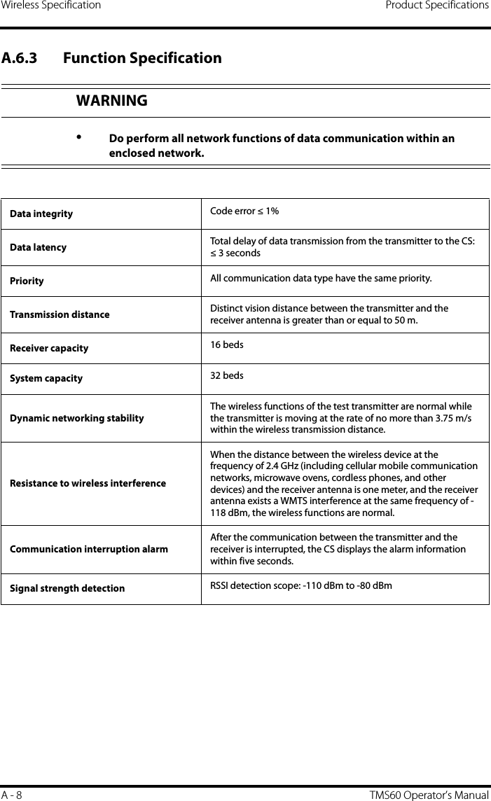
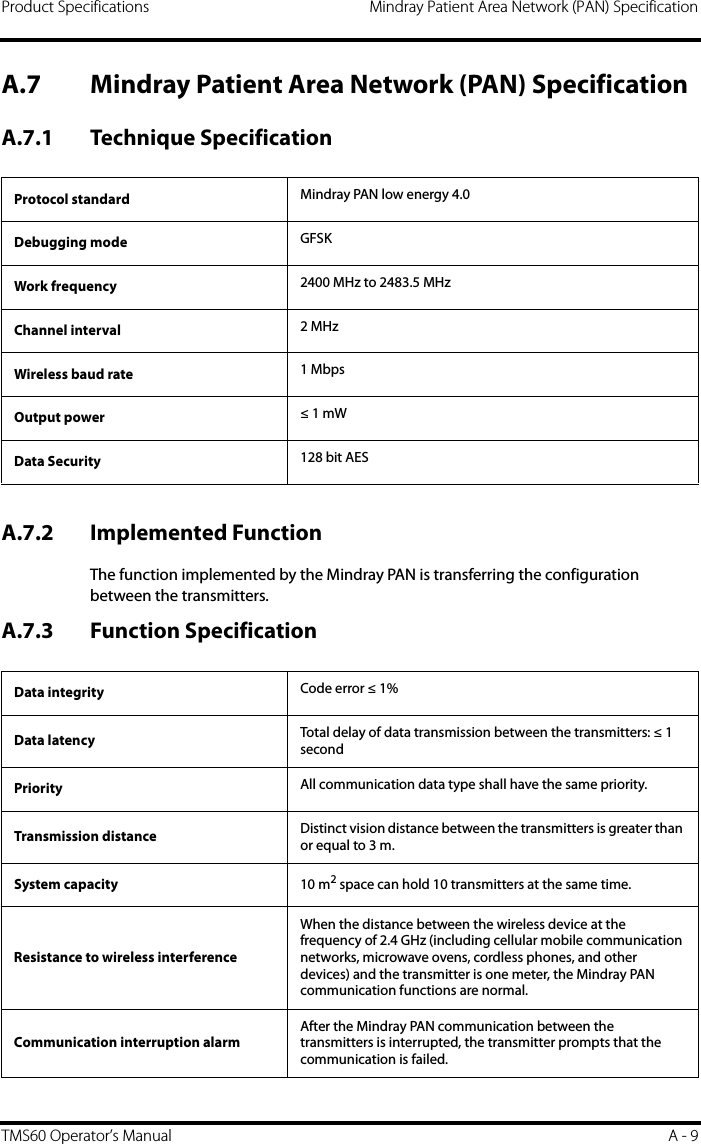
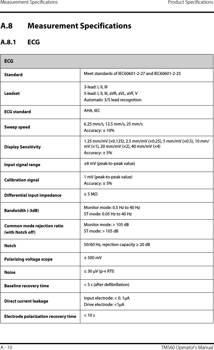
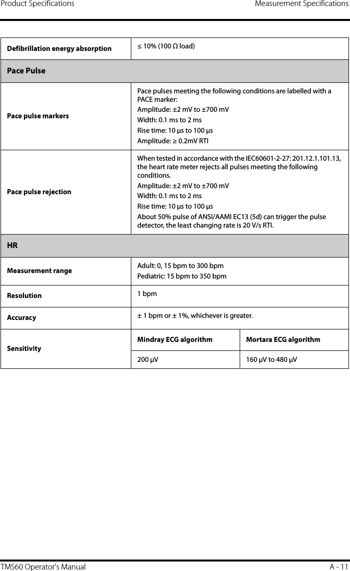
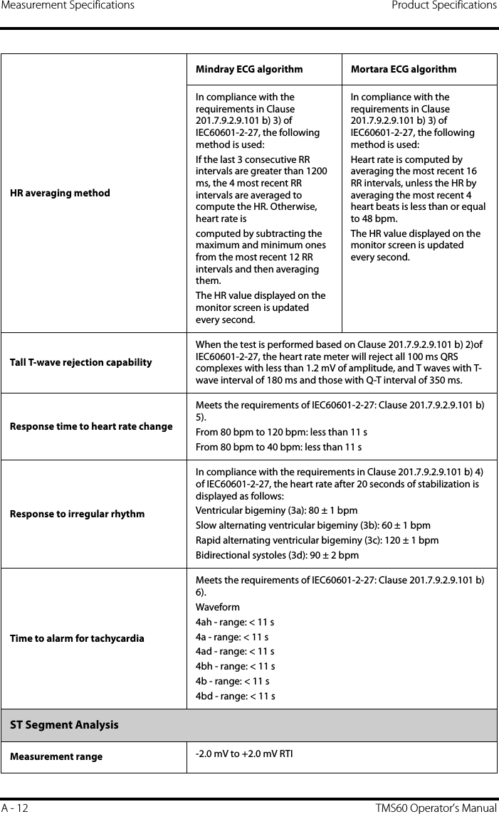
![Product Specifications Measurement SpecificationsTMS60 Operator’s Manual A - 13Resolution 0.01 mVAccuracy -0.8 mV to +0.8 mV: ± 0.02 mV or ± 10%, whichever is greaterBeyond this range: Not specifiedArrhythmia AnalysisArrhythmia analysis classificationsMindray ECG algorithm Mortara ECG algorithmAsystole, VFib/VTac, Vtac, Vent. Brady, Extreme Tachy, Extreme Brady, PVCs/min, Pauses/min, R on T, Run PVCs, Couplet, Multif. PVC, PVC, Bigeminy, Trigeminy, Tachy, Brady, Pacer Not Pacing, Pacer Not Capture, Missed Beat, Nonsus. Vtac, Vent. Rhythm, Pause, Irr.Rhythm, AfibAsystole, VFib, Vtac, Extreme Tachy, Extreme Brady, PVCs/min, Pauses/min, R on T, Run PVCs, Couplet, Multif. PVC, Bigeminy, Trigeminy, Tachy, Brady, Pacer Not Pacing, Pacer Not Capture, Vent. Rhythm, Pause, Irr.RhythmQT AnalysisQTc formula Bazett, Fridericia, Framingham, and HodgesMindray ECG algorithm Mortara ECG algorithmQT measurement range [200, 800] ms [300, 600] msQT accuracy[200, 800] ms: ± 30 msBeyond this range: Not specified[300, 600] ms: ± 30 msBeyond this range: Not specifiedQT resolution[200, 800] ms: 4 msBeyond this range: Not specified[300, 600] ms: 2 msBeyond this range: Not specifiedQTc measurement range [200, 800] ms [300, 600] msQTc resolution[200, 800] ms: 1 msBeyond this range: Not specified[300, 600] ms: 1 msBeyond this range: Not specifiedQT-HR measurement range Adult: [15, 150] bpmPediatric: [15, 180] bpmN/A](https://usermanual.wiki/Mindray-BIO-Medical-electronics/TD608FE/User-Guide-2678251-Page-183.png)