Mine Safety Appliances 10105756 MSA GX2 Electronic Cylinder Holder User Manual Galaxy GX2
Mine Safety Appliances Company MSA GX2 Electronic Cylinder Holder Galaxy GX2
UserManual.wiki
>
Mine Safety Appliances
>
10105756 User Manual
manual
Navigation menu
Upload a User Manual
Namespaces
Wiki Guide
HTML
PDF
Info
Views
User Manual
Discussion / Help
Navigation

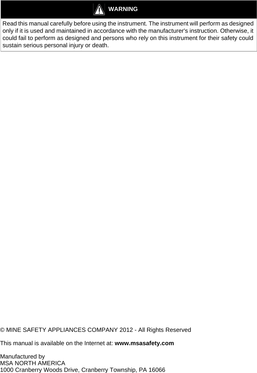
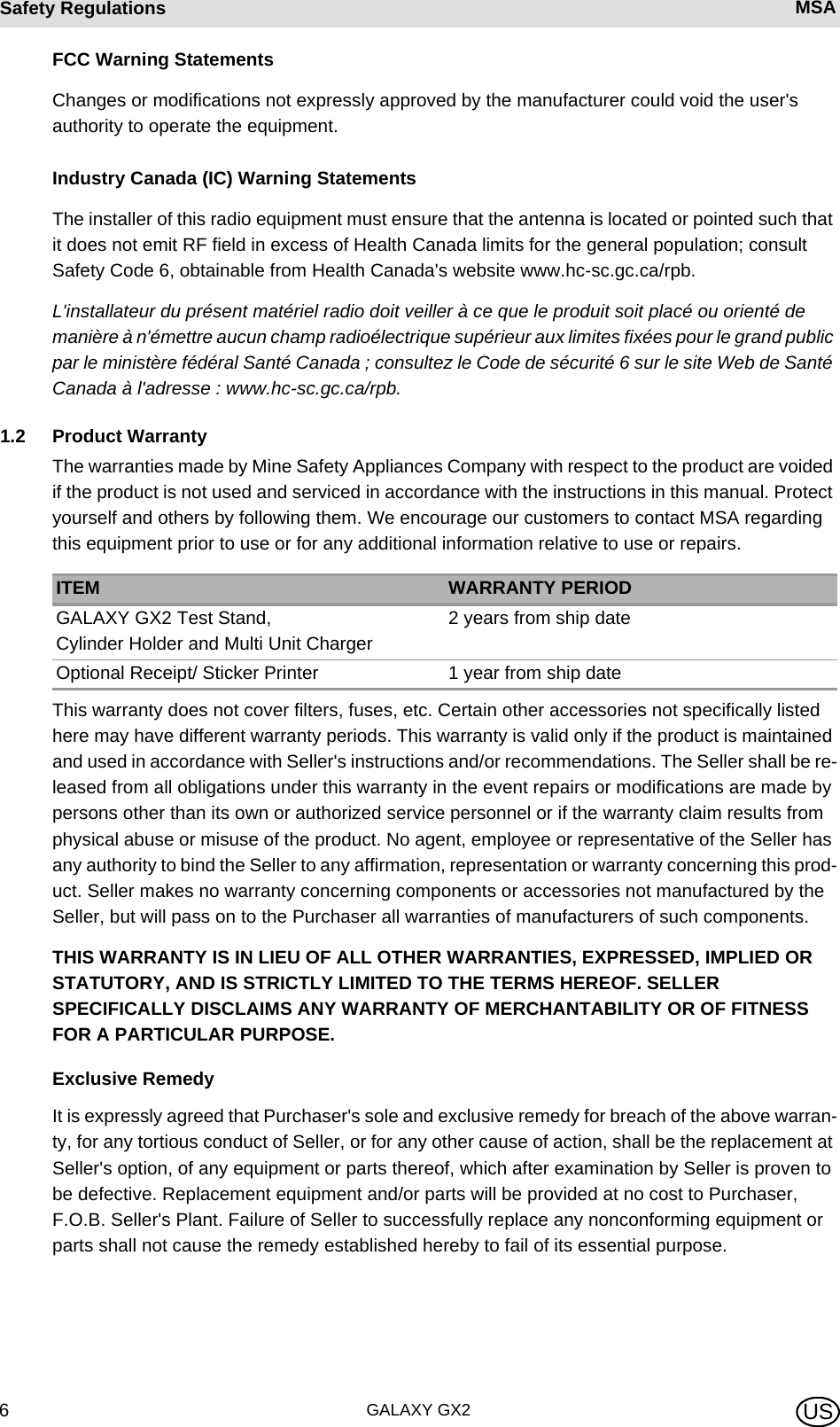
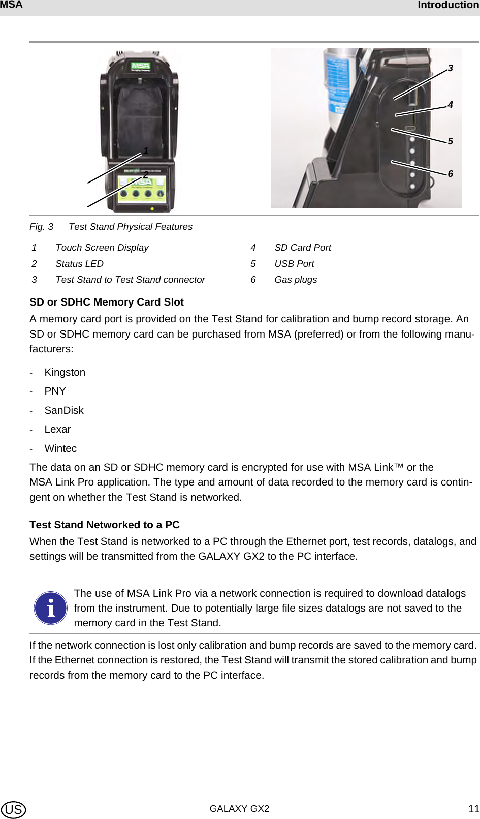
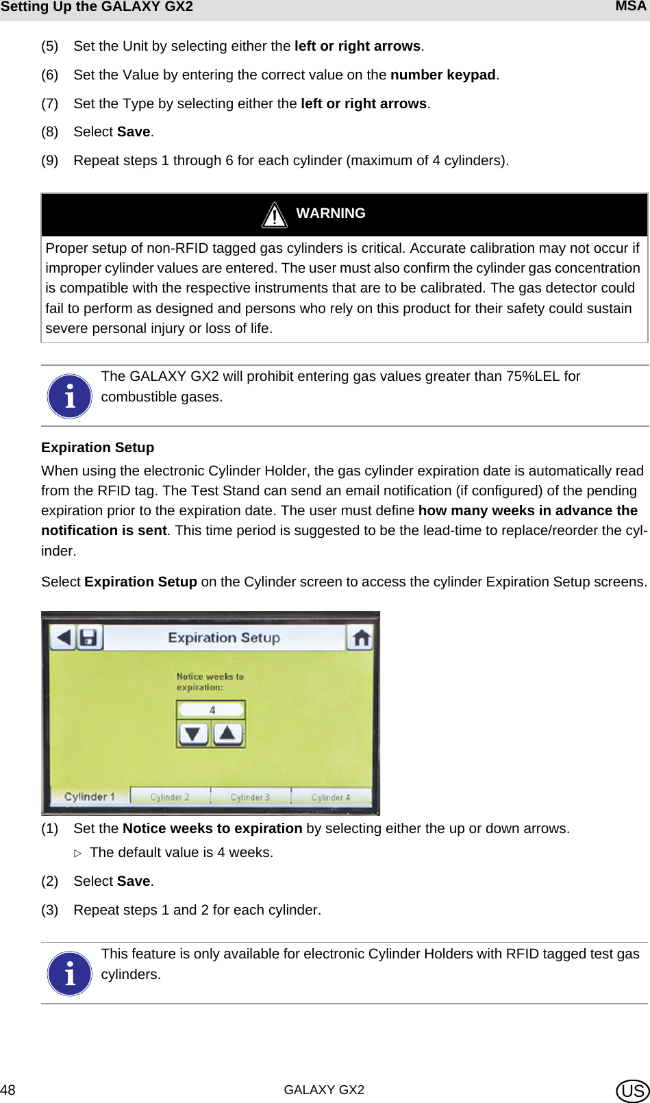
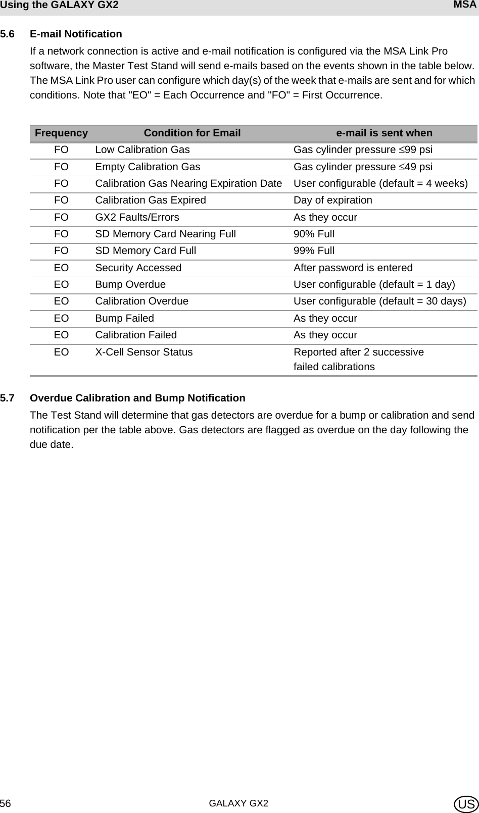
![GALAXY GX28Introduction MSA US2 IntroductionCongratulations on purchasing the GALAXY GX2 Automated Test System, the next generation Test Stand and instrument management system from MSA. This system is used exclusively with the ALTAIR® family of gas detectors. This manual uses the terms instrument and gas detector to represent that entire line of ALTAIR gas detection instruments.In this manual the user will learn to install and configure the GALAXY GX2 Test Stand and optional attachments, and test gas detectors. Maintenance, Troubleshooting, and Technical Specifications sections are also provided.The Test Stand uses a sophisticated internal processor and simple to use touch screen display for the configuration of calibration parameters and gas detector settings, and for gathering instru-ment data. Each Test Stand and optional attachments can be wall or desk mounted to serve the needs of the user. Constructed of durable composite polymers, this equipment is designed for normal indoor applications and operates within a broad temperature range of 0º to 40ºC in non-condensing hu-midity atmospheres.The principal components of the GALAXY GX2 include the Test Stand and optional electronic or non-electronic Cylinder Holder, Multi-Unit Charger, and Receipt/ Sticker Printer. These compo-nents [ Fig. 1] are designed to be attached (excluding the printer), to avoid accidental separation during operation.Fig. 1 The GALAXY GX2 Automated Test System](https://usermanual.wiki/Mine-Safety-Appliances/10105756/User-Guide-1733964-Page-8.png)
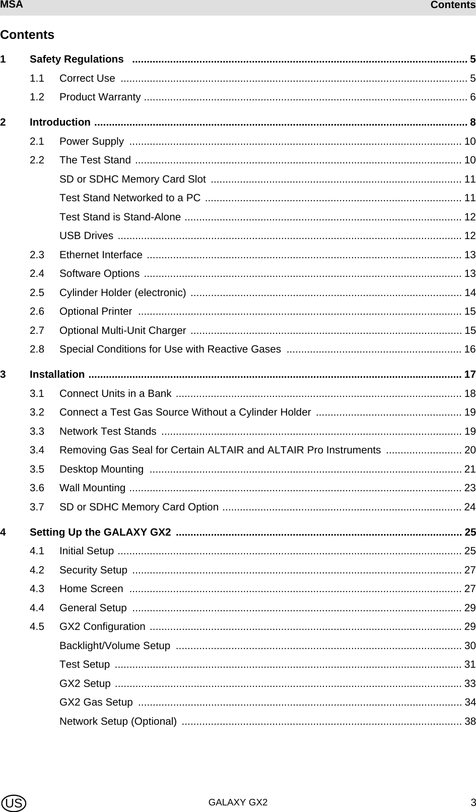
![MSA AUERMSA IntroductionGALAXY GX2 9USThe Test Stand is a standalone unit that can accommodate one gas detector of the ALTAIR family. However, each Test Stand contains the plumbing and electronic ports to simultaneously connect a total of 10 Test Stands and four Cylinder Holders (electronic or non-electronic).For applications where multiple Cylinder Holders are connected, the Test Stand Expanded Sole-noid option must be ordered. This option allows the Test Stand to open and close up to four Cyl-inder Holder valves for gas detectors that may require multiple cylinders for test purposes. For example, an ALTAIR 5/5X with the standard 4 sensors plus a toxic sensor likely requires two gas cylinders.The electronic Cylinder Holder is designed to read a Radio Frequency Identification (RFID) tag embedded in a plastic ring on MSA test gas cylinders. The RFID tag contains cylinder parameters that are necessary for successful calibration operations, providing the customer with an excep-tionally easy setup experience. Gas cylinder information is automatically populated without user intervention when using the RFID-tagged gas cylinders.If MSA test gas cylinders are not used, the non-electronic version of the Cylinder Holder is avail-able. This configuration [ Fig. 2] requires the user to manually enter cylinder parameters.Fig. 2 Non-electronic Cylinder Holder and Test Stand.A USB port is provided on the Test Stand that may be used with the Digital Secure USB key to change instrument settings via the touch screen. This function allows for convenient fleet management capabilities. The port may also be used for an optional Receipt/ Sticker Printer, to print calibration/bump stickers or paper receipts after an instrument test.The primary functions of the Test Stand are to calibrate and bump the ALTAIR family of gas de-tectors. For a detailed definition of these processes, please refer to:http://www.safetyequipment.org/userfiles/File/calibration_statement-2010-Mar4.pdfIn the following sections of this manual the user will learn how to install the GALAXY GX2 Automated Test System, set up its functionality, and perform instrument tests. The hardware, soft-](https://usermanual.wiki/Mine-Safety-Appliances/10105756/User-Guide-1733964-Page-9.png)
![GALAXY GX210Introduction MSA USware, and configuration options anticipate the user's needs and provide superb efficiency in this next generation Automated Test System.GALAXY GX2 System Features and OptionsThe GALAXY GX2 automatically identifies the type of gas detector inserted into the Test Stand. Based on user-defined settings, the Test Stand then performs bump tests and/or calibrates the instrument. The data collected from each test event is stored to a memory card [ chapter 2.2] and/or optional MSA Link™ Pro software application for data analysis (refer to the MSA Link Pro end-user manual).2.1 Power SupplyThe Test Stand supplies power to the attached electronic Cylinder Holders. The Test Stand and Multi-Unit charger are powered individually by one of the following methods:-Power Module: Input power requirements: 100 - 240 VAC, 47 - 63 Hz (Several different prong types are available for world-wide AC sockets).-Optional Vehicle Module 12/24 VDC (For use in a cigarette lighter socket).2.2 The Test StandThe Test Stand performs the following functions:-Bump or calibration testing per user setup.-Records test results to the optional memory card and to an optional networked PC interface.-Sends gas detector Instrument Periodic and/or Session datalogs to a networked PC interface.-Provides optional instrument charging capability.-USB key allows gas detector settings to be changed securely, with the touch of the Test Stand screen.-Permits printing of test results to an instrument sticker or receipt, with the optional Receipt/ Sticker Printer.-Sends e-mail notification of system alerts per user setup.An LED indicator shows the status of the Test Stand:-Green light indicates that the Test Stand hardware and software are fully functional.-Blinking green light indicates that the Test Stand is performing the user specified test or data-log download.-Blinking yellow light indicates that the Test Stand is in error and cannot be used for gas detec-tor testing. Diagnostic information is available as described on the "GX2 Status" screen on the Test Stand and in the Troubleshooting section of this manual [ chapter 6].-Red light indicates that the last calibration or bump test failed.NOTICEUse of a power supply not specified by MSA will void the instrument warranty and could cause damage to the GALAXY GX2.](https://usermanual.wiki/Mine-Safety-Appliances/10105756/User-Guide-1733964-Page-10.png)
![GALAXY GX212Introduction MSA USTest Stand is Stand-AloneIf the GALAXY GX2 is not networked to a PC interface the memory card will save each calibration and bump test record. Incomplete records will not be saved. If networked and e-mail alerts are configured, the Test Stand will generate an email alert once the memory card reaches 90% and again at 99% capacity.Once a memory card reaches full capacity, the Test Stand will be in fault and prohibit any unit from performing tests in that bank, until corrected. The Test Stand can be configured to erase the memory card, or the user can insert a replacement. An optional end cap [ Fig. 4] can be placed over the port to protect the memory card and all external connections.Fig. 4 Optional End CapUSB DrivesTwo optional USB Keys [ Fig. 5] are available for purchase with the GALAXY GX2 Automated Test System:-Digital Secure USB Key: This black key is inserted in the USB port on the Test Stand in order to change gas detector settings. The key ensures only authorized users can change settings on ALTAIR gas detectors; a security step in addition to the four-digit password.-MSA Link Pro Key: This red key is used to enable the MSA Link Pro application on a single PC. More information about this key can be found in the software product end-user manual. Fig. 5 Digital Secure Key and MSA Link Pro KeyThe memory card should only be removed when no test activity is occurring. Events that occur while no memory card is installed will not be stored in the Test Stand.If no memory card is used, only the most recent bump or calibration record is stored to the Test Stand internal memory. DUMMY!Awaiting final plastic - mid March](https://usermanual.wiki/Mine-Safety-Appliances/10105756/User-Guide-1733964-Page-12.png)
![MSA AUERMSA IntroductionGALAXY GX2 13US2.3 Ethernet InterfaceTwo Ethernet Interfaces are provided on the rear of the GALAXY GX2 [ Fig. 6]. The ports allow for the connection and communication distribution between multiple Test Stands. If networking to a computer, one USB port on the Master Test Stand is used to communicate with the MSA Link Pro software application.Fig. 6 Test Stand Ethernet jacks 2.4 Software OptionsThe GALAXY GX2 functions as a standalone system, but the optional MSA Link Pro software application can be used to network the Test Stand to a PC through an Ethernet cable. This appli-cation provides a best-in-class user interface and data analysis toolset to quickly identify issues or concerns that require user action.MSA Link Pro provides the user:-Database storage of instrument Periodic and Session datalogs.-Automatic or customized reports from the collected data.-Single glance notification of instruments that are overdue for calibration or bump test.-Email notifications of GALAXY GX2 and instrument warnings and error messages.-Single setting configuration of all GALAXY GX2 units in a bank. No need to individually configure each Test Stand.To learn more about installing and using MSA Link Pro, refer to the software product end-user manual.Users may use the free MSA Link software application and an IR dongle [ chapter 7.2] to communicate directly with their gas detector. MSA Link allows a user to upload and download instrument settings, and download datalogs.](https://usermanual.wiki/Mine-Safety-Appliances/10105756/User-Guide-1733964-Page-13.png)
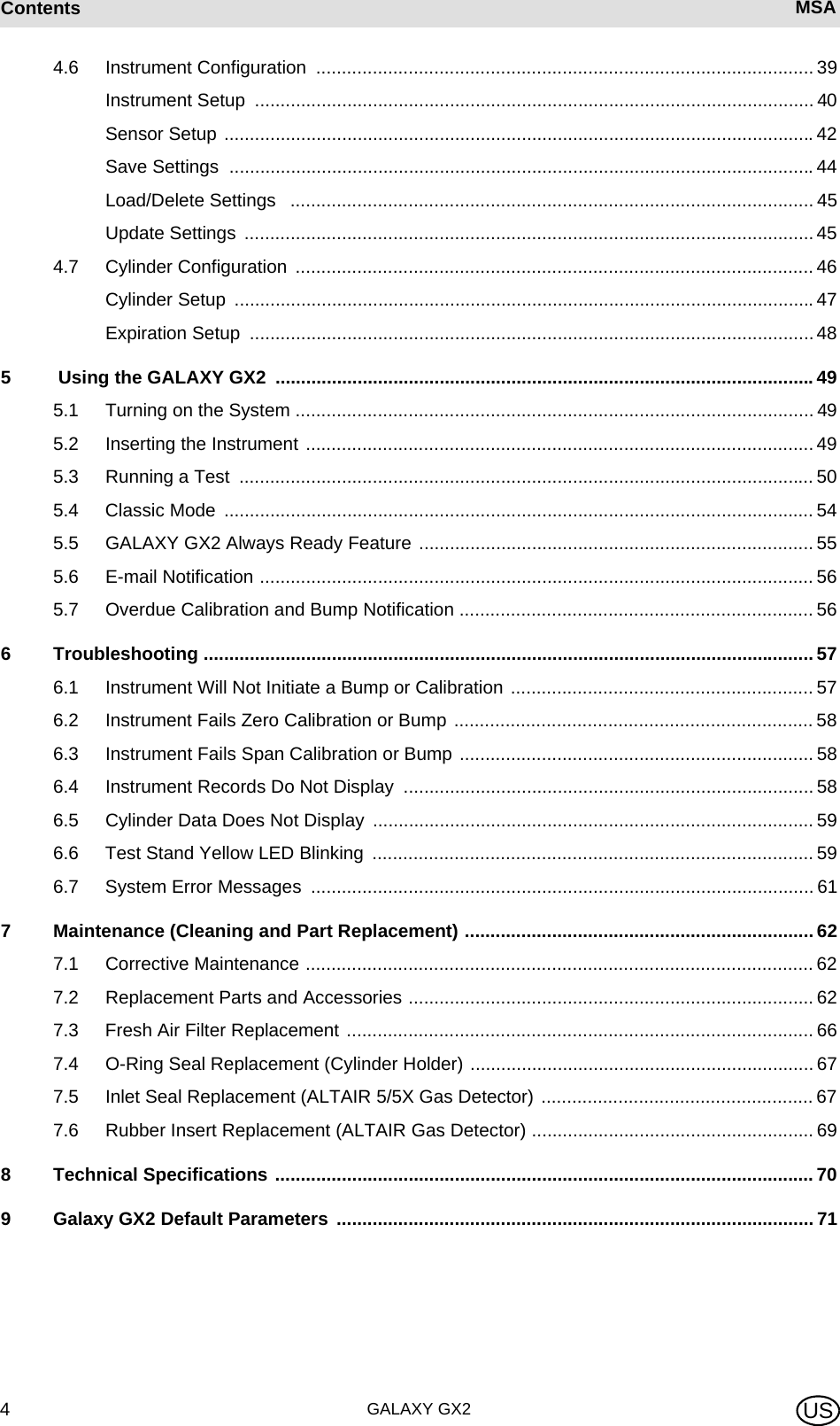
![GALAXY GX214Introduction MSA US2.5 Cylinder Holder (electronic)The electronic Cylinder Holder can accommodate one test gas cylinder and includes:Fig. 7 Cylinder Holder Physical Features1 Light Band 2 RFID Tag 3 Internal Pressure Regulator & SensorMulti-Color Light Band RFID Tag Gas Identification Pressure Regulator & SensorIndicates gas bottle functionality.-Green indicates a bottle is completely functional, and gas parameters are within pressure and expiration date limits.-Yellow indicates low calibration gas, or gas is nearing its expira-tion date. -A blinking yellow light band indi-cates a hardware problem with the cylinder holder.-Red indicates an empty calibra-tion gas bottle, or that gas has expired. Reads the RFID tag of the MSA test gas cylin-der and transmits:-the gas type-gas concentration-expiration date-lot number-cylinder part numberto the Test Stand. The RFID tag is only availa-ble on MSA-branded test gas cylinders shown in the Maintenance section [ chapter 7].Reads the pressure of the gas cylinder and transmits that information to the Test Stand.-When gas pressure drops to approximately 99 psi (6.89 bar) a warning will display and the display numbers appear yellow.-Once pressure drops to ap-proximately 49 psi (3.45 bar) the display numbers appear red.-Once pressure drops to less than 5 psi (0.34 bar) the Test Stand will prohibit test-ing with that cylinder.123](https://usermanual.wiki/Mine-Safety-Appliances/10105756/User-Guide-1733964-Page-14.png)
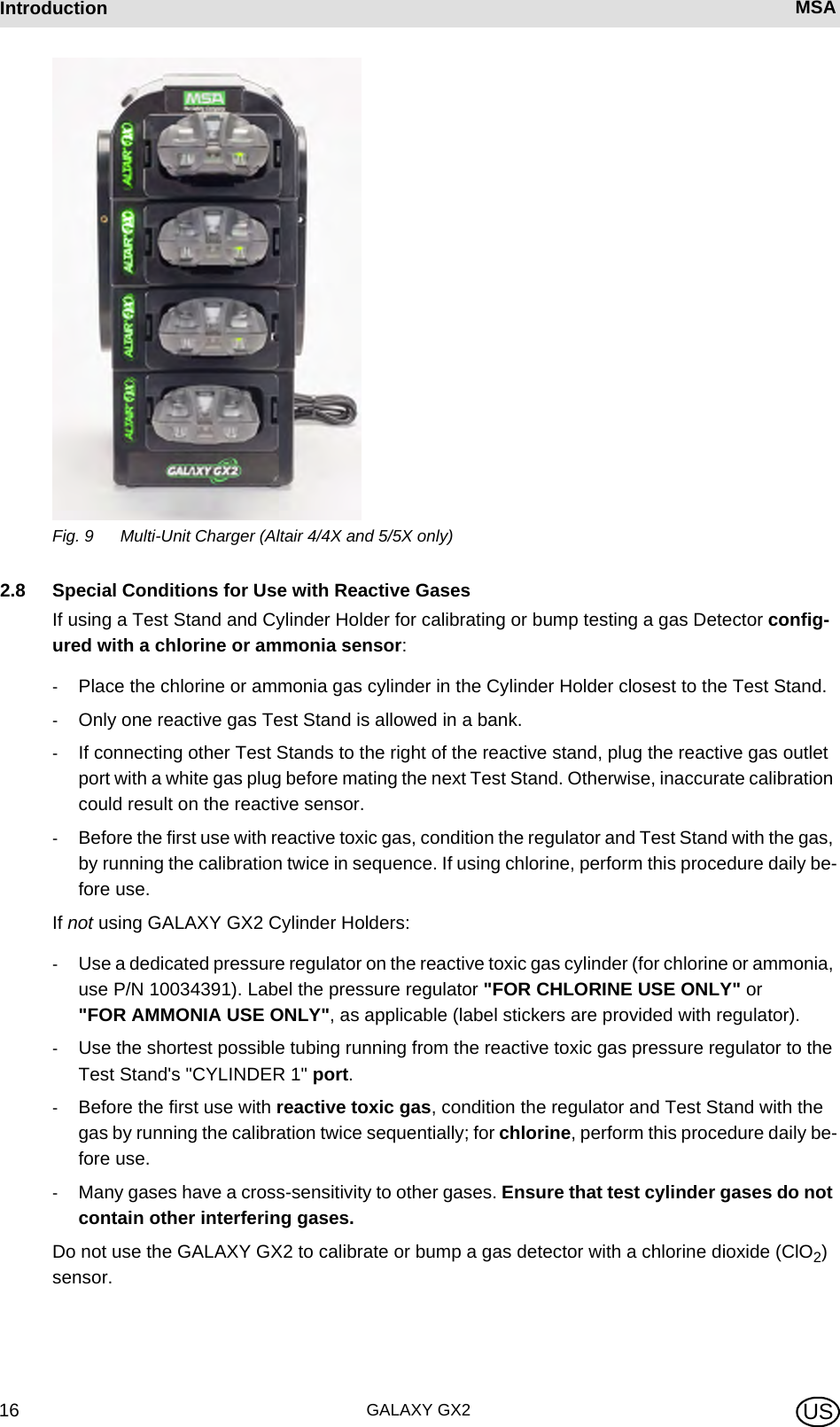
![MSA AUERMSA IntroductionGALAXY GX2 15US2.6 Optional PrinterThe Printer can print calibration and bump result receipts and calibrations stickers for gas detec-tors [ Fig. 7]. The Receipt/ Sticker Printer uses a USB cable to connect to the port of the farthest right Test Stand [ Fig. 3].Labels are available in two formats [ chapter 7.2]: -Format #1: Calibration Sticker only (2 cm x 2 cm square label).-Format #2; Receipt and Sticker combined.Fig. 8 Optional Printer2.7 Optional Multi-Unit ChargerThere are two configurations of the optional Multi-Unit Charger (MUC). The ALTAIR 4/4X MUC can simultaneously charge up to four ALTAIR 4/4X gas detectors. Similarly the ALTAIR 5/5X MUC can charge four 5/5X gas detectors. Each Multi-Unit Charger contains its own power supply and does not connect electrically to the Test Stand. The housing is designed to physically connect to each other, whether bench-top or wall-mounted (if desired).The light indicators on the Multi-Unit Charger are defined as follows:-Red indicates that the unit is charging-Green indicates that the unit is fully charged or no unit is inserted.There can be as much as a 10 minute window between when the instrument battery indicator shows charged and the Multi-Unit charger status indicator changes. The instrument indicator is the most accurate and will indicate the true charge state of the battery. DUMMVerify the Multi-Unit Charger indicator lights red when an instrument is inserted. A fully charged instrument will momentarily flash red and the indicator will light green. If the red light does not engage the instrument may not be seated properly on the charging prong.Instruments whose battery is completely discharged will be need to trickle-charge prior to normal charging operations. Such instruments will show a green LED during the trickle-charge period until normal charging is initiated, at which time the red LED will be active.](https://usermanual.wiki/Mine-Safety-Appliances/10105756/User-Guide-1733964-Page-15.png)
![MSA AUERMSA InstallationGALAXY GX2 17US3 InstallationThe GALAXY GX2 is a simple to install system that can be desktop or wall mounted. Setup re-quires simple tools and just a few minutes of time.Carton ContentsThe GALAXY GX2 system will be shipped with the following:-Test Stand (including gas plugs, barbs and fresh air filter)-Power Supply (if ordered)-Spare Parts Kit (gas tubing barbs and plugs)-Ethernet Cable (short cable for connection between Test Stands)-Product CD-Quick Start Guide -Screen Protector (installed on the display screen)Tools Needed-Phillips head (cross-head) screwdriver.As stated in the Introduction, the GALAXY GX2 is designed for the connection of up to 10 Test Stands and four Cylinder Holders [ Fig. 10]. Test Stands must be assembled sequentially on the right-hand side of the first. Cylinder Holder(s) must be installed on the left-hand side of the first Test Stand for best gas flow into all Test Stands.Fig. 10 Test Stands and Cylinder Holders properly installed in a bankTest gas cylinders containing Chlorine or Ammonia must be installed according to the directions in the Special Conditions for Use with Reactive Gases section [ chapter 2.8].When installing the GALAXY GX2, please consider the environmental needs of your facility. If the customer desires, the GALAXY GX2 can be used in a ventilated area to assist in disbursing the test gas exhaust.](https://usermanual.wiki/Mine-Safety-Appliances/10105756/User-Guide-1733964-Page-17.png)
![GALAXY GX218Installation MSA USThis manual provides steps for desktop and wall mounting. The following sections describe the proper installation for various GALAXY GX2 configurations:-Connect Units in a Bank (Test Stands and Cylinder Holders) [ chapter 3.1]-Connect a Test Gas Source Without a Cylinder Holder (optional) [ chapter 3.2]-Network Test Stands (optional) [ chapter 3.3]-Removing Gas Seal for Certain ALTAIR and ALTAIR Pro Instruments [ chapter 3.4]-Desktop Mounting [ chapter 3.5]-Wall Mounting [ chapter 3.6]-SD or SDHC Memory Card Option [ chapter 3.7]3.1 Connect Units in a Bank(1) On the left-hand side of the Test Stand, ensure all five barb fittings are in place and straight-ened before connecting a Cylinder Holder or another Test Stand.(2) Press the two units together until the barb fittings are fully inserted and the screw holes in the flange align.(3) Insert one of the supplied screws into the front and two screws into the back of the flange.](https://usermanual.wiki/Mine-Safety-Appliances/10105756/User-Guide-1733964-Page-18.png)
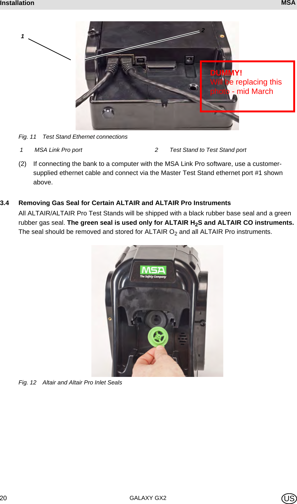
![MSA AUERMSA InstallationGALAXY GX2 19US(4) If connecting multiple Test Stands, remove the white gas plugs [ Fig. 3] from all units ex-cept the farthest right Test Stand. If using ammonia or chlorine test gas, read the restriction found under chapter 2.8 “Special Conditions for Use with Reactive Gases” regarding the white plugs.(5) Continue adding Test Stands to the right and Cylinder Holders to the left [ Fig. 10].3.2 Connect a Test Gas Source Without a Cylinder HolderIf high-pressure, high-capacity test gas cylinders are preferred, an optional demand regulator (p\n 710289) is available for cylinders with pressure less than (<) 3000 psi. Testing from an inde-pendent gas source will require additional setup effort, as described in the Cylinder Configuration section [ chapter 4.7].(1) On the left-hand side of the Test Stand, ensure all five barb fittings are in place and straight-ened.(2) Place the user-supplied regulator onto the gas cylinder and secure a length of tubing onto its outlet.(3) Securely fit the end of the tubing over the appropriate barb fitting on the GALAXY GX2.3.3 Network Test StandsTest Stands that are banked together should be connected through the provided Ethernet cable. The Master Test Stand is the one located on the furthest right of the bank.(1) Insert the short Ethernet cable into the left side jack of each Test Stand (1) and connect it to the right side jack of the neighboring unit (2) [ Fig. 11]. ZOne interconnect Ethernet cable is included with each Test Stand.When connecting two or more Test Stands ensure the white plugs are secured on the right side of the farthest right unit to prevent gas leakage.](https://usermanual.wiki/Mine-Safety-Appliances/10105756/User-Guide-1733964-Page-19.png)
![MSA AUERMSA InstallationGALAXY GX2 21US3.5 Desktop Mounting(1) Place the GALAXY GX2 on a flat, stable surface.(2) Insert the power supply into the GX2 power jack [see chapter 4.1 for first-time power up ini-tialization].(3) If using MSA Cylinder Holders, the left most Cylinder Holder should have a fresh air filter attached to the top port.The Test Stand display pivots for ease of viewing.](https://usermanual.wiki/Mine-Safety-Appliances/10105756/User-Guide-1733964-Page-21.png)

![MSA AUERMSA InstallationGALAXY GX2 23US3.6 Wall MountingWhen wall mounting the Test Stand (and applicable Cylinder Holder), MSA recommends steps 1-5 from the Desktop Mounting section [ chapter 3.5] above be completed prior to installing on the Din Rail. For a large configuration of Test Stands and Cylinder Holders, MSA recommends several people be used for installing or uninstalling from the DIN rail.(1) Complete steps 1-5.(2) Secure the optional DIN rail Clips to the rear of the GALAXY GX2, using the included screws.(3) Mount the DIN rail (Type Omega) to the wall by securing it with wall anchors or other suitable fasteners.(4) Align the DIN rail clips over the wall-mounted DIN rail and snap into place.(5) To remove from the DIN rail, grasp the back of the units and pull outward.](https://usermanual.wiki/Mine-Safety-Appliances/10105756/User-Guide-1733964-Page-23.png)
![GALAXY GX224Installation MSA US3.7 SD or SDHC Memory Card OptionThe Test Stand can accommodate an SD or SDHC memory card, inserted in the port on the right hand side of the farthest right Test Stand. Only one memory card can be used in a bank.To install the memory card:(1) Ensure that memory card is not write-protected or locked.(2) Insert the memory card into the port, located on the right side of the Test Stand [ Fig. 13].(3) Place the optional end cap over the port to protect the memory card.(4) To remove the memory card push the card to eject it from the port.Fig. 13 SD or SDHC Memory Card InstallationThe memory card should not be removed when testing or datalog downloads are in process. The Test Stand will not store events that occur while a memory card is re-moved.](https://usermanual.wiki/Mine-Safety-Appliances/10105756/User-Guide-1733964-Page-24.png)
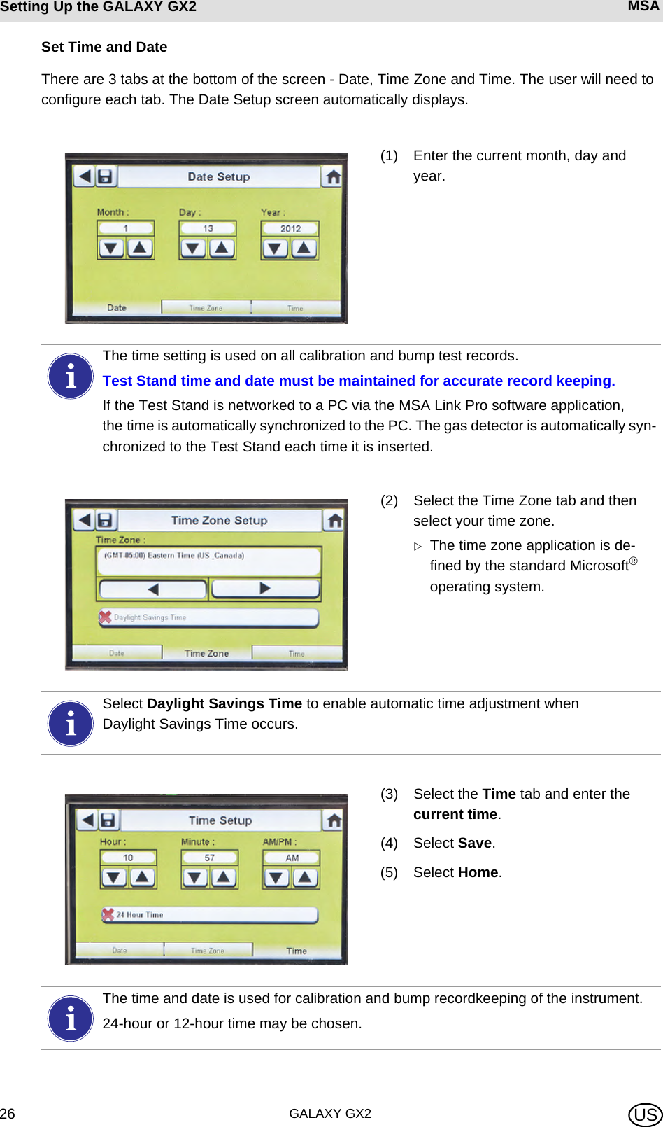
![MSA AUERMSA Setting Up the GALAXY GX2GALAXY GX2 25US4 Setting Up the GALAXY GX2The GALAXY GX2 Automated Test System is shipped with the most common default options and therefore requires minimal set up. A table of all default settings is provided in the Galaxy GX2 De-fault Parameters section [ chapter 9] at the end of this manual. Configuration settings are de-scribed in this chapter and can be changed to meet your individual needs via the touch screen display.The touch screen is intended for interaction with the user's bare finger. Gloves may interfere with screen operation. The attached touch screen protector inhibits damage and should not be re-moved. Replacement screen protectors can be purchased from MSA.4.1 Initial SetupThe first time the Test Stand is powered on an initial set of screens will appear for system config-uration. The GALAXY GX2 logo momentarily displays and then the unit's version number. This is followed by the first of three required screens.Language SetupThe Language Setup screen automatically displays.NOTICEUse of sharp objects on the touch screen could cause damage.(1) Select your language from the list.ZThe language zone selection de-termines the date format, either MM/DD/YYYY or DD/MM/YYYY.(2) Select Save.(3) Select Home.123Changes must be saved on all screens by selecting the Save icon (shown above). If the user selects the Back Arrow (W) without saving, a prompt will display. Select Yes to save or No to discard changes.](https://usermanual.wiki/Mine-Safety-Appliances/10105756/User-Guide-1733964-Page-25.png)
![MSA AUERMSA Setting Up the GALAXY GX2GALAXY GX2 27US4.2 Security SetupThe Security Setup is the last screen to automatically display. Setting a numeric password prohibits unauthorized changes to the GALAXY GX2.4.3 Home ScreenThe Home Screen displays the relevant parameters for the Test Stand and electronic Cylinder Holders.Fig. 14 Test Stand Home ScreenIf no password is desired, enter "0000" to disable the password feature. The Test Stand is shipped with the password dis-abled.(1) Enter a four-digit password for the GALAXY GX2.(2) Select Save. Retain a copy of the password for your records.(3) Select Home.(4) The GALAXY GX2 Home screen displays [ Fig. 14].To change the password, return to the Security Setup screen, enter a new password and select Save.If your password has been misplaced, call MSA Customer Service for reset instructions.1 Test Mode 3 Gas Cylinder Pressure Gauge2 Gas Detector Datalog Download Mode 4 Gas Detector Charging status2314](https://usermanual.wiki/Mine-Safety-Appliances/10105756/User-Guide-1733964-Page-27.png)
![GALAXY GX228Setting Up the GALAXY GX2 MSA USTest ModeBump Only, Calibration Only, or Bump/Cal on Fail. The mode is selected in the Test Setup section [ chapter 4.5] of this manual.Gas Detector Datalog DownloadOn or Off. This setting is described in the GALAXY GX2 Setup, Datalog section [ chapter 4.5] of this manual.Pressure GaugesDisplay test gas cylinder pressure from the electronic Cylinder Holder only. Selecting a pressure gauge displays gas cylinder details.Charging StatusIf gas detector charging is installed the battery symbol will display in the lower left corner of the screen. When the gas detector is charging, the battery symbol will cycle. When the instrument is either fully charged or not present, the battery symbol will be solid green.There can be as much as a 10 minute window between when the instrument battery indicator shows charged and the Test Stand battery symbol shows solid green. The instrument indicator is the most accurate and will indicate the true charge state of the battery.GX2 ConfigurationProvides access to GALAXY GX2 settings. (Password screen will display if configured.) Steps are found under GALAXY GX2 Setup section [ chapter 4.2] of this manual.](https://usermanual.wiki/Mine-Safety-Appliances/10105756/User-Guide-1733964-Page-28.png)
![MSA AUERMSA Setting Up the GALAXY GX2GALAXY GX2 29USInstrument RecordsProvides the most recent calibration and/or bump record for each instrument in the Test Stand bank. This button is only active on the Master Test Stand. All other Test Stands will report their data to the Master Test Stand for display.4.4 General SetupThe following settings can be changed from their default values after entering the password. Select GX2 Configuration from the Home screen. The Administrator screen displays.Fig. 15 Administrator screenThe Administrator screen provides configuration options for the Test Stand (1), instrument (2) and test gas cylinders (3).The GX2 Status selection (4) provides detailed information about the Test Stand that can be used to troubleshoot identified errors.The Export Data selection (5) is used to upload instrument settings to a docked gas detector.4.5 GX2 ConfigurationTo configure the settings for the GALAXY GX2 select GX2 Configuration [ Fig. 15] on the Administrator screen.1 GX2 configuration for Test Stand [ chapter 4.5] 4 GX2 Status selection 2 Instrument configuration [ chapter 4.6] 5 Export Data selection3 Test gas cylinder configuration [ chapter 4.7]](https://usermanual.wiki/Mine-Safety-Appliances/10105756/User-Guide-1733964-Page-29.png)
![GALAXY GX230Setting Up the GALAXY GX2 MSA USFig. 16 GX2 ConfigurationBacklight/Volume SetupSelect Backlight/Volume Setup on the GALAXY GX2 Configuration screen [ Fig. 16] to access the Backlight/Volume screens.Volume TabThe user can set the volume for audio indicators.(1) Set the volume by selecting either the left or right arrows on the volume screen. ZThe default volume level is set to Medium.(2) Select Save.Backlight TabThe user can set the backlight intensity of the display screen.(1) Set the backlight by selecting either the left or right arrows on the backlight screen. ZThe default backlight level is set to Medium.(2) Select Save.1 Network Setup [ chapter 4.5] 5 GX2 Setup [ chapter 4.5]2 Time/Date Setup [ chapter 4.1] 6 Backlight/Volume Setup [ chapter 4.5]3 Test Setup [ chapter 4.5] 7 Languages [ chapter 4.1]4 Security Setup [ chapter 4.2]The Time/Date Setup, Security Setup, and Languages Setup have been described in the Initial Setup section [ chapters 4.1 and 4.2].](https://usermanual.wiki/Mine-Safety-Appliances/10105756/User-Guide-1733964-Page-30.png)
![MSA AUERMSA Setting Up the GALAXY GX2GALAXY GX2 31USTest SetupSelect Test Setup on the GALAXY GX2 Configuration screen [ Fig. 16] to access the Test Setup screens. There are 4 tabs that can be selected under Test Setup: Mode, Calibration, Bump and COMB. Mode TabSelect the Mode tab to setup the Test Stand for Bump Only, Calibration Only, Bump/Cal on Fail, or Classic Mode.-Bump Only setting bumps an instrument and reports a pass or fail status.-Calibration Only performs a full calibration on an instrument every time it is docked.-Bump/Cal on Fail (default setting) will bump an instrument. If it fails the bump, the Test Stand automatically performs a full calibration.-Classic Mode (3= enabled) initiates the user-selected test mode each time an instrument is inserted in the Test Stand. The Classic Mode feature means, "always test". To return to the GX2 Configuration screen, select the back arrow W on the top left cor-ner of the screen.The GALAXY GX2 will reduce the backlight intensity automatically after a period of inactivity. Either select a button or insert an instrument to return the intensity to the user selected level. Disabling Classic Mode (2 = disabled) sets the Test Stand to calibrate or bump an in-strument only if the due date approaches. The Test Stand will read the last calibration (or bump) date and add the GX2 Calibration (or Bump) Interval. If the setting is within 5-days of the calibration (or bump) due date, the Test Stand will begin the test. If the calibration (or bump) due date is not within 5-days, no test will initiate, the screen will display "Test Not Due" and the instrument will be turned off after 5-minutes.A memory card must be used if Bump Only test is enabled and Classic Mode is disa-bled. Otherwise, the Test Stand will bump the instrument each time it's inserted.](https://usermanual.wiki/Mine-Safety-Appliances/10105756/User-Guide-1733964-Page-31.png)
![MSA AUERMSA Setting Up the GALAXY GX2GALAXY GX2 33USGX2 SetupTo access GX2 Setup, select GX2 Setup on the GALAXY GX2 Configuration screen [ Fig. 16].GALAXY GX2 TabThe following options are available on this screen:-USB Drive Enable setting allows the user to gather data from the Memory card with a USB drive that can be inserted in the port on the right side of the unit. The default setting is Off (2).-Display psi or bar options display the units of pressure on the gauges on the home screen and pressure screen. Selecting one of these options (3) will disable the other option. The default setting is psi.-Erase GALAXY GX2 Memory erases all data on the memory card. The user will be prompted to confirm the action before erasure occurs.Datalog TabThe following options are available on this screen:-Download Periodic setting will download the Periodic Datalog from the instrument following the specified calibration or bump test. Downloading can be enabled or disabled. The default setting is disabled (2).-Download Session will download the Session Datalog from the instrument following the spec-ified calibration or bump test. It contains the date and time stamp of instrument events, such as turn on/off, alarms, and calibrations. The default setting is disabled (2). -Erase After Download erases all current and past data once downloaded and verified by the MSA Link Pro database. The default setting is enabled (3).](https://usermanual.wiki/Mine-Safety-Appliances/10105756/User-Guide-1733964-Page-33.png)
![GALAXY GX234Setting Up the GALAXY GX2 MSA USDatalog Download SequenceThe following flowchart shows the sequence of events for a datalog download:Print TabSelect the Print tab to print a calibration sticker or receipt [available from MSA, Fig 8]. The stick-er or receipt will print in the language setting of the Master Test Stand.-Print Sticker setting will print a calibration or bump sticker each time the GALAXY GX2 successfully calibrates or bumps an instrument. A sticker will not print if the instrument fails the test. -Print Receipt will print a receipt and embedded calibration sticker after calibration, or receipt only after a bump. The receipt will print whether the instrument passes or fails, the calibration sticker will only print with a passed calibration. GX2 Gas SetupThe GALAXY GX2 Test Stand can accept test cylinder gas from the optional Cylinder Holders (electronic and non-electronic) or from a user provided regulated gas source. Cylinder data can be set for up to six gas types per cylinder. The following are the maximum number of gases each instrument can process:-ALTAIR and ALTAIR Pro: 1 gas-ALTAIR 4/4X: 4 gases (typically 1 cylinder with quad gas)-ALTAIR 5/5X: 5 gases (typically quad gas + 1 toxic gas)-ALTAIR 5IR/5XIR: 6 gasesDatalogs are not written to the memory card because of potentially large file sizes. If the unit is not networked to the MSA Link Pro software application, instrument datalogs cannot be downloaded with the GALAXY GX2. In this situation the user can use the MSA IR dongle and the free MSA Link application to download datalogs from the instrument.In order to effectively manage the time required to download datalogs, it is recommend-ed that datalogs be downloaded and erased after each test. This will result in storage of only the most recent information in the instrument datalog, minimizing time to download the information.Test Starts (Bump or Calibration) Test Finishes Datalog download starts immediately Datalog download finishesTest results (PASS or FAIL) screen is displayedIf either the Session or Periodic datalogs are Enabled for downloading, the test status of the calibration or bump will not display until AFTER the datalog download is com-plete.](https://usermanual.wiki/Mine-Safety-Appliances/10105756/User-Guide-1733964-Page-34.png)
![GALAXY GX236Setting Up the GALAXY GX2 MSA USIf the Test Stand is NOT using Cylinder Holders, the gas connections on the left-most GALAXY GX2 Test Stand [ Fig. 17] are as follows from top:-Fresh Air-Cylinder 1-Cylinder 2-Cylinder 3-Cylinder 4Fig. 17 Gas inlets on the Test StandIf the Test Stand is using Cylinder Holders [ Fig. 10], they are set up as follows from right to left:-Cylinder 1 is the closest to the Test Stand.-Cylinder 2 is to the left of Cylinder 1.-Cylinder 3 is to the left of Cylinder 2.-Cylinder 4 is to the left of Cylinder 3.Fresh Air is the top port on the last installed (left-most) Cylinder Holder.](https://usermanual.wiki/Mine-Safety-Appliances/10105756/User-Guide-1733964-Page-36.png)
![MSA AUERMSA Setting Up the GALAXY GX2GALAXY GX2 37USChanging CylindersChanging test cylinders in the Cylinder Holders is a simple procedure.To change an RFID tagged test gas cylinder, using an electronic Cylinder Holder:(1) Unscrew and remove a cylinder with its attached RFID tag from the Cylinder Holder.(2) Screw a new test gas cylinder into the Cylinder Holder.The Multi-Color Light Band will indicate test gas cylinder functionality as described in the System Features -Cylinder Holder section [ chapter 2.5].(3) Navigate to the Home screen and select the appropriate cylinder pressure gauge from the touch screen.ZThe selected Cylinder screen will appear, as shown.To change a test gas cylinder, using a non-electronic Cylinder Holder:(1) Remove the test gas cylinder from the Cylinder Holder.(2) Unscrew the pressure regulator.(3) Reattach the pressure regulator to the new test gas cylinder.(4) Insert it into the Cylinder Holder.(5) Navigate to the Home screen [ Fig. 23] and select the cylinder gauge to ensure the GALAXY GX2 is reading the gas type.The new cylinder's RFID tag will automatically populate the cylinder data fields on the Cylinder Setup screens.Ensure the GX2 is reading the pressure and gas type.If a new gas type is used, the user must manually enter the cylinder data fields on the Cylinder Setup screens, as described in the Cylinder Configuration section [ chapter 4.7].](https://usermanual.wiki/Mine-Safety-Appliances/10105756/User-Guide-1733964-Page-37.png)
![GALAXY GX238Setting Up the GALAXY GX2 MSA USNetwork Setup (Optional)The GALAXY GX2 can be networked to a PC with the MSA Link Pro software application. Net-working (single or multiple connected units) allows the user to remotely gather and analyze data, monitor performance, and configure the Test Stand.An Ethernet cable supporting 10/100 Mb must be connected to the farthest right Ethernet jack when facing the front of the unit, (shown in Fig. 6) and connected to the PC or network router.To configure the network setup, navigate to the GX2 Configuration screen and then select Network Setup. The Network Setup screen displays. It is recommended to use a Static IP ad-dress between the Master Test Stand and the MSA Link Pro application.(1) If DHCP is disabled (2), select Edit Address on the Network Setup screen. ZThe Static IP Edit screen displays.If background gases could be present, connect a Zero Air Cylinder to any port on the Cylinder Holder. MSA provides an RFID-tagged Air cylinder for this purpose. This re-quires a calibration station with expanded solenoid capacity. Refer to the Introduction section [ chapter 2] for more information about the expanded solenoid option.Selecting DHCP Enable (3) allows the GALAXY GX2 to automatically receive an IP address from the network. It is recommended that the DHCP server always assign the same IP address to the Test Stand to maintain communications with the MSA Link Pro application.Corporate networks may require the involvement of an IT department for setup.](https://usermanual.wiki/Mine-Safety-Appliances/10105756/User-Guide-1733964-Page-38.png)
![MSA AUERMSA Setting Up the GALAXY GX2GALAXY GX2 39US(2) Enter the Static IP Address on the number keypad. ZThe yellow highlighted cursor then moves to the Subnet field.(3) Enter the Subnet on the number keypad. ZThe yellow highlighted cursor then moves to the Gateway field.(4) Enter the Gateway on the number keypad. ZThe yellow highlighted cursor then moves to the Subnet field.(5) Select Save.4.6 Instrument ConfigurationThe GALAXY GX2 Automated Test System allows the user to configure a limited set of gas de-tector settings at the Test Stand, as defined below:Gas Detector Settings Configurable at the Test StandThe user can save those settings to a reusable file for later use [The settings are stored on the Digital Secure USB (black) key. No instrument setting files are stored locally. The Instrument Configuration screens are accessed only when an instrument is inserted in the Test Stand. To configure an instrument, insert the Digital Secure USB (black) key and navigate to the Administrator page. Select GX2 Configuration screen [ Fig. 23] and then Instrument Configuration. The Instrument Configuration screen displays.-Time & Date (automatically set to the Test Stand time & date)-24-Hour Time-Cal Gas Value-Company Name-Company Department Name-User Name-Exposure Warning-Exposure Alarm-TWA-STEL-Deficiency Warning-Deficiency Alarm-Alarm Set-point-Latching Enabled-Vibration Motor On/Off-LED On/Off-Horn Enable-Man Down (if applicable)-Enable/Disable Sensor Channel-Cal Due On/Off-Cal Due Interval-Average Enabled-Peak Enabled-Datalog IntervalAll settings entered in Instrument Configuration must be saved on the respective screens. To apply settings to the instrument, the user must select Update Settings before removing the instrument.](https://usermanual.wiki/Mine-Safety-Appliances/10105756/User-Guide-1733964-Page-39.png)
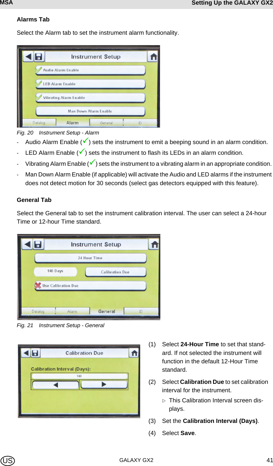
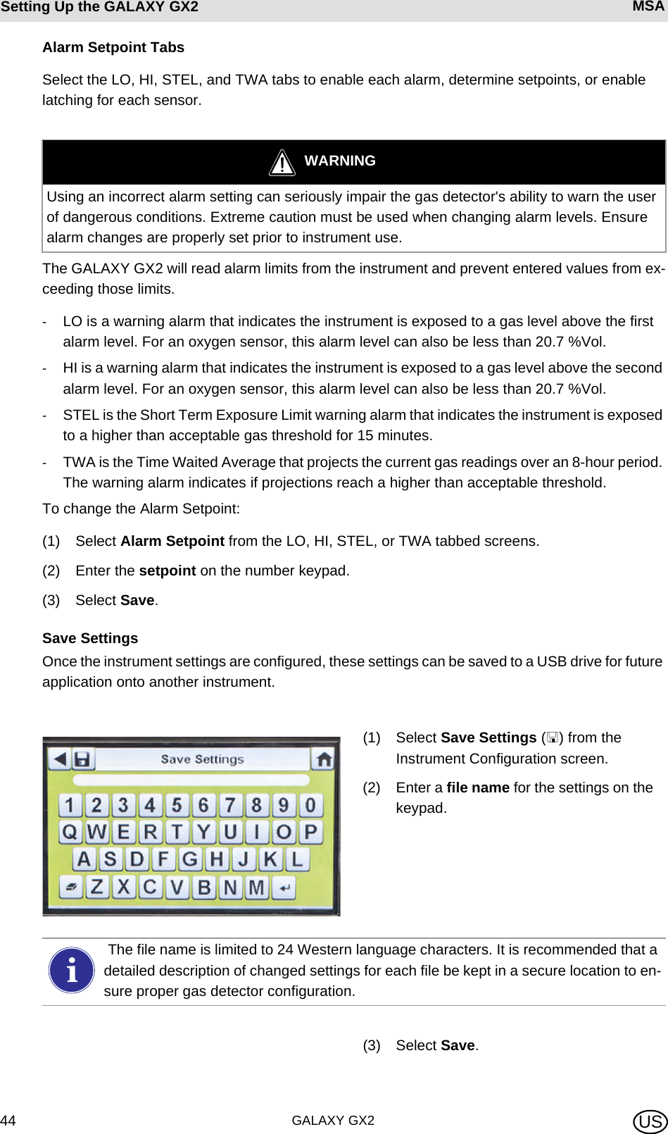
![GALAXY GX240Setting Up the GALAXY GX2 MSA USFig. 18 Instrument ConfigurationInstrument SetupThe user can set the instrument's datalog gathering functionality, alarms, calibration intervals, and identification through the 4 tabs on the Instrument Setup page.Select Instrument Setup [ Fig. 18] from the Instrument Configuration screen.Datalog TabSelect the Datalog tab to set how the instrument compiles sensor reading data during a set interval.Fig. 19 Instrument Setup - Datalog-Average Enabled (3) compiles an average of the sensor readings during the set interval time.-Peak Enabled (3) records the highest reading during the set interval time. -Edit Interval allows the user to set a specific interval time frame for the recording of instrument data to its datalog. The smaller this interval, the more frequent the data will be stored to the datalog. Large datalogs will require longer download times.1 Instrument Setup 4 Load Settings2 Sensor Setup 5 Update Settings3 Save Settings](https://usermanual.wiki/Mine-Safety-Appliances/10105756/User-Guide-1733964-Page-40.png)
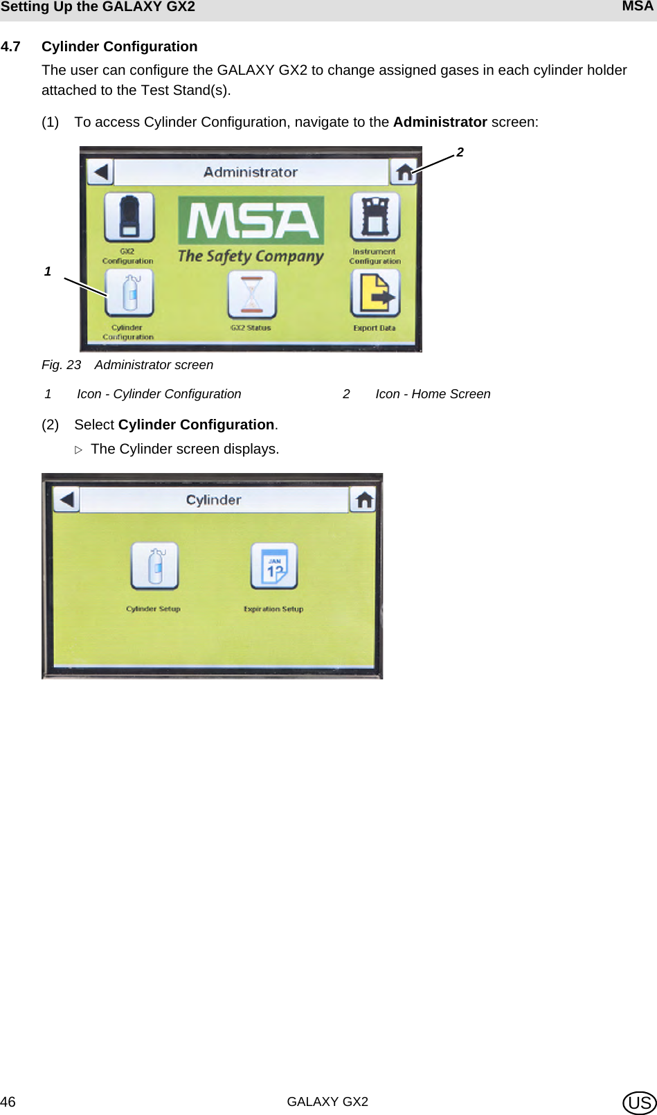
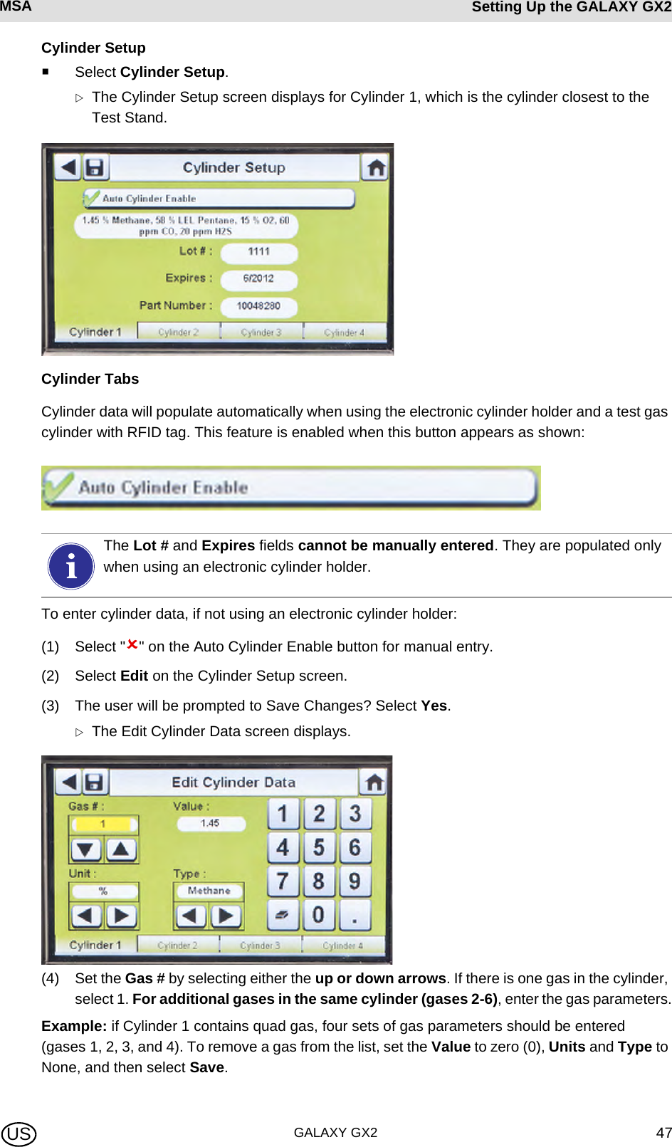
![GALAXY GX242Setting Up the GALAXY GX2 MSA USID TabSelect the ID tab to set the instrument name, company, and department.Fig. 22 Instrument Setup - ID(1) Select User Name to assign a designation.(2) Enter the name on the keypad.(3) Select Save and then select the back arrow.(4) Select Company Name.(5) Enter the name on the keypad.(6) Select Save and then select the back arrow.(7) Select Department Name.(8) Enter the name on the keypad.(9) Select Save.Sensor SetupThe GALAXY GX2 displays the gas types the instrument is programmed to detect. The user can enable or disable sensor settings, change span value, enable or disable alarms, and set alarm latching. Adding new sensors or changing sensor types cannot be done in the GALAXY GX2. These tasks must be completed at an MSA-authorized service center.For proper operation, ensure the GALAXY GX2 and instrument Calibration Due intervals are the same value. If not selected, calibration occurs based on the gas de-tector Cal Interval. This can lead to more (or less, depending on setting) frequent instru-ment calibration and unwanted overdue indications.To apply settings to the instrument select Update Settings on the Instrument Configu-ration screen [ Fig. 18], before removing the instrument from the GALAXY GX2.](https://usermanual.wiki/Mine-Safety-Appliances/10105756/User-Guide-1733964-Page-42.png)
![MSA AUERMSA Setting Up the GALAXY GX2GALAXY GX2 43USOptions TabSelect the Options tab to set Span Value and enable or disable the sensor for that gas type.(1) Select Span Value to enter the calibration and bump span value. Check the instrument's product user manual for recommended span value of each sensor. ZThe GALAXY GX2 will prohibit entering span values outside the instrument range. The in-strument will transmit its range to the Test Stand.(2) Enter the Span Value on the number keypad.(3) Select Save and then select the back arrow.(1) Select Sensor Setup from the Instru-ment Configuration screen [ Fig. 18]. ZThis screen displays the sensors cur-rently installed in the instrument.(2) Select the sensor that you wish to con-figure on the Sensor Setup screen.WARNINGUsing an incorrect span value can seriously impair the gas detector's ability to warn the user of dangerous conditions. The gas detector could fail to perform as designed and persons who rely on this product for their safety could sustain severe personal injury or loss of life.](https://usermanual.wiki/Mine-Safety-Appliances/10105756/User-Guide-1733964-Page-43.png)
![MSA AUERMSA Setting Up the GALAXY GX2GALAXY GX2 45USLoad/Delete Settings Configured instrument settings can be loaded into the GALAXY GX2 and applied to an instrument, provided the black USB key is inserted into the Master Test Stand as described in the USB Drives section [ chapter 2.4] of the System Features section.This feature is particularly useful when configuring a large number of instruments. Unused set-tings may be permanently deleted from the Test Stand. Pre-defined settings from a USB drive can be efficiently transferred.To load or delete settings:(4) Select the up or down arrows to indicate the file name of the setting to apply.(5) Select Load to apply the setting to the instrument. Select Delete to permanently remove the setting from the USB drive.(6) Select the Back Arrow on the top left of the screen to navigate to the Instrument Configuration screen.Update SettingsSelect Update Settings to save or delete the settings on the instrument.(1) Insert a USB drive with the Saved set-tings into the port, under the memory card port on the right side of the Test Stand.(2) Select Instrument Configuration on the Home screen.(3) Select Load Settings on the Instrument Configuration screen.Saved settings on the black USB key display.Repeat the Load Settings and Update Settings steps for each new instrument that is to be changed.](https://usermanual.wiki/Mine-Safety-Appliances/10105756/User-Guide-1733964-Page-45.png)
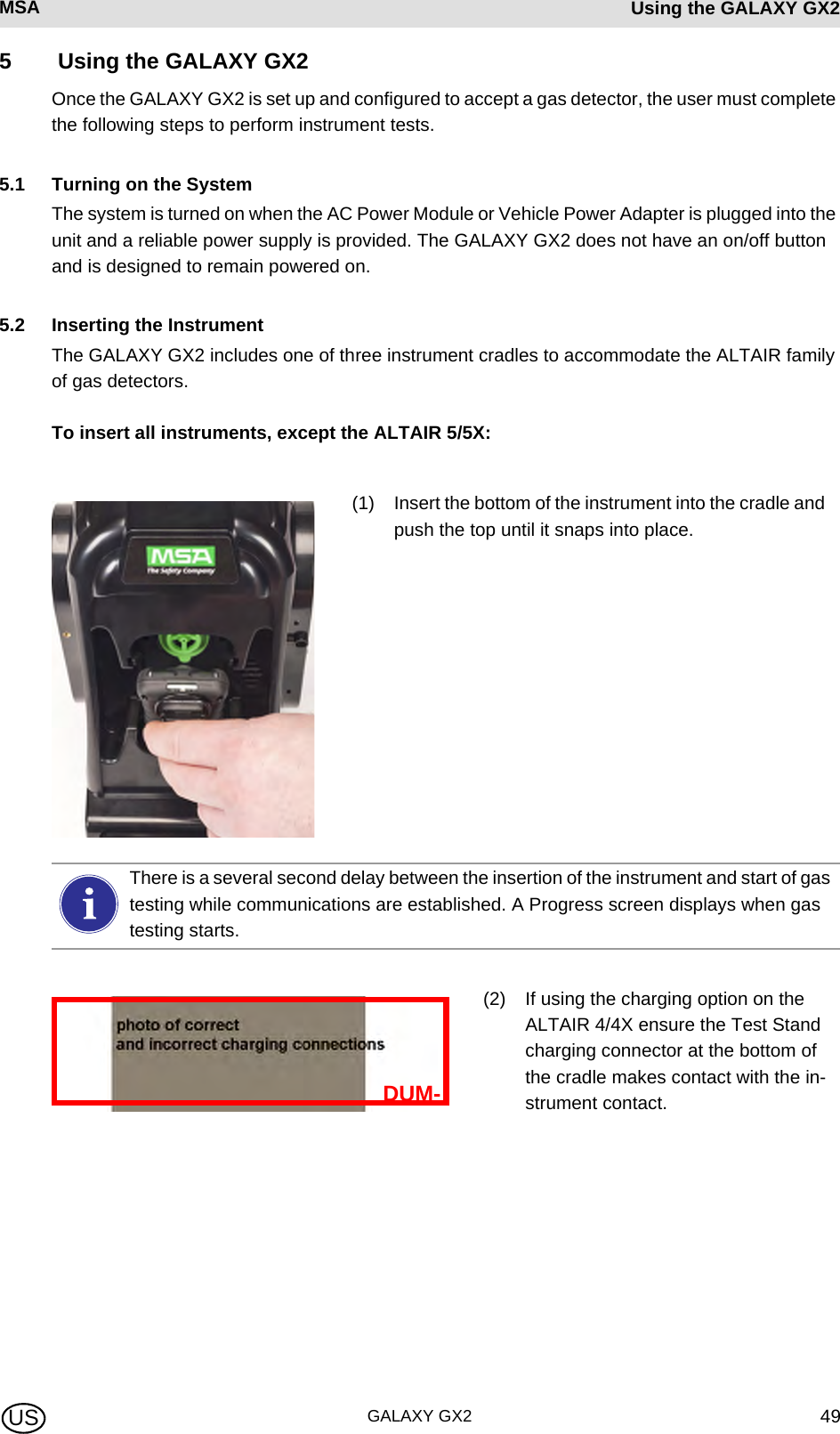
![GALAXY GX250Using the GALAXY GX2 MSA USTo insert the ALTAIR 5/5X:5.3 Running a TestComplete the following steps to run an instrument test:(1) Turn on the gas detector and allow it to warm up per the appropriate instrument manual.(2) Ensure the test gas cylinder tubing is properly attached to the barb fitting of the gas inlet, or that the cylinder(s) are properly screwed into the Cylinder Holder(s) and contain gas.(3) Verify the selected mode, indicated in the top left corner of the Home screen. (Calibration Only, Bump Only, or Bump/Cal on Fail.)(1) Insert the instrument into the cradle, sliding the bottom over the charging connector. If your Test Stand has the optional charging feature, ensure the charging connector at the bottom of the cradle makes contact with the instrument contact.(2) Pivot the instrument in the cradle up-wards, into the gas inlet sleeve (see arrow). The instrument will lock into place, once properly positioned.(3) Ensure the red LEDs on the instru-ment flash when communicating with the Test Stand.There is a several second delay between the insertion of the instrument and start of gas testing while communications are established. A Progress screen displays when gas testing starts.WARNINGInstrument must warm up per the instrument manual before attempting calibration; failing to al-low unit to warm up can cause erroneous test results, which can cause inaccurate calibrations.If the desired mode is not set, refer to the GALAXY GX2 Setup section [ chapter 4.5] of this manual.](https://usermanual.wiki/Mine-Safety-Appliances/10105756/User-Guide-1733964-Page-50.png)
![MSA AUERMSA Using the GALAXY GX2GALAXY GX2 51US(4) Insert the instrument into the Test Stand cradle.(5) The GALAXY GX2 will read the instrument configuration via the IR link up to 10 seconds. If the LED lights on the instrument flash red do not remove the instrument. This indicates that IR communications are in progress.(6) After the initial IR communications, the bump or calibration progress screen displays that in-cludes up to six gas types and a progress bar.For the Bump Progress screen, an hourglass symbol will display in each sensor box until that sen-sor's bump is complete. A green checkmark (3) or red X (2) will display for each sensor when the Bump test is complete.Before inserting an ALTAIR or ALTAIR Pro into the Test Stand, press and hold the instrument Test button for one second. The screen on the gas detector should display Gas? prior to inserting it into the Test Stand (see photo below).If the Test Stand is configured to download the session log and/or periodic log from the instrument, the download will occur after the calibration or bump test. Refer to the GALAXY GX2 Setup section [ chapter 4.5] to configure this feature.](https://usermanual.wiki/Mine-Safety-Appliances/10105756/User-Guide-1733964-Page-51.png)
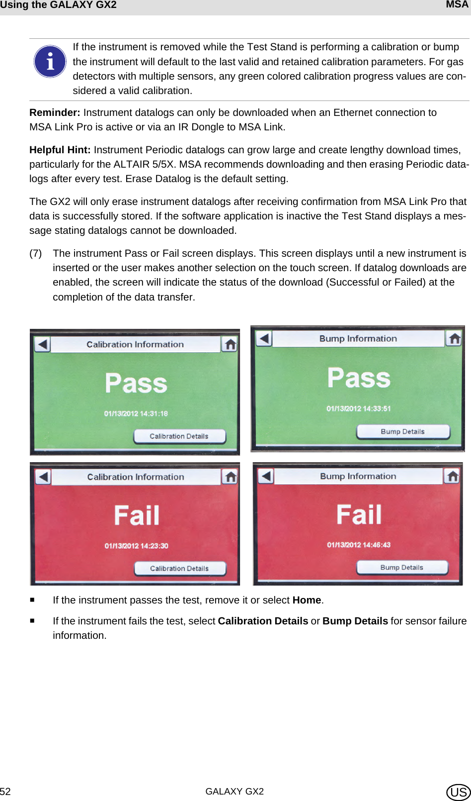
![MSA AUERMSA Using the GALAXY GX2GALAXY GX2 53USIf a sensor failed during a bump, attempt to calibrate the instrument. Refer to calibrate an instrument in this manual.If the unit fails the calibration, review the troubleshooting section [ chapter 6] of this man-ual.If Cylinder is Configured Incorrectly or Gas is Not AvailableThe Test Stand will verify the instrument sensors are compatible with the gases in the cylinder(s). If not, the GALAXY GX2 will: (1) Prompt the user to run a partial bump or calibration.(2) If a partial bump or calibration is acceptable, select Yes. If not, select Home to navigate to the administrator screen.ZIf a partial bump or calibration is performed the test results screen displays. ZDashes (---) under the results column indicate unavailable gases for the test.If the instrument fails the bump test while the mode is set to Bump/Cal on Fail the Test Stand will automatically calibrate the instrument.The Calibration Information screen displays two columns for the sensors: As Found and Target. As Found is what the Test Stand detected prior to calibration. The Target col-umn specifies the span gas value that is being applied. If the sensor passes calibration, the Target value becomes the new calibration point.If using the ALTAIR 4/4X or 5/5X the instrument will shut off if not removed from the Test Stand within 5 minutes after test completion. If the GALAXY GX2 is equipped with the charging option the instrument will begin charging after shutoff.](https://usermanual.wiki/Mine-Safety-Appliances/10105756/User-Guide-1733964-Page-53.png)
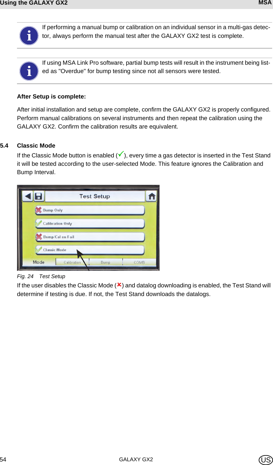
![MSA AUERMSA Using the GALAXY GX2GALAXY GX2 55US5.5 GALAXY GX2 Always Ready FeatureThe Always Ready feature is a capability of the ALTAIR 4X and ALTAIR 5X with the following software versions:-ALTAIR 4X: v2.03 and higher-ALTAIR 5X: v1.11 and higherThe feature permits the gas detector to be automatically calibrated on a user-defined interval. The most common use of this feature allows the user to configure the GALAXY GX2 to automatically calibrate an instrument prior to the start of work-shift.The following configurations must be set to allow the Always Ready feature to be active:When these conditions are met, every hour the instrument will internally check its clock and last calibration time and date. If the next calibration is due to occur within the hour, the gas detector powers itself on and the Test Stand will initiate the calibration. Following calibration, the Test Stand will power off the instrument and begin charging. The sequence repeats based on the Calibration Due Interval.Instrument GALAXY GX2 Test Stand-Calibration Due Interval = any interval [ chapter 4.6]. Ensure that this interval is the same as on the Test Stand.-Valid calibration at the desired time of day-Charging version of the Test Stand-Calibration Due Interval = any interval [ chapter 4.6]. Ensure that this interval is the same as on the gas detector.-Test Mode = CalibrationThe Always Ready feature is solely based on Calibration Due Interval, not on time of day. Each subsequent calibration starts within the same hour of the day as the previous calibration.If for some reason the instrument fails calibration two times in a row, the Always Ready feature will be disabled in the instrument to prevent calibration gas from being unnec-essarily consumed. The user must diagnose the cause of the failed calibrations and in-itiate a valid calibration at the desired time of day.](https://usermanual.wiki/Mine-Safety-Appliances/10105756/User-Guide-1733964-Page-55.png)
![MSA AUERMSA TroubleshootingGALAXY GX2 57US6 TroubleshootingUse the following information to diagnose abnormal conditions.6.1 Instrument Will Not Initiate a Bump or Calibration(1) Ensure the instrument is turned on and errors are not displayed.(2) If using an ALTAIR or ALTAIR Pro, press and hold the button for one second. The screen on the gas detector must display Gas? prior to insertion into the Test Stand.(3) Ensure the instrument is seated securely in the Test Stand cradle.(4) If using the ALTAIR 5 or 5X, ensure the instrument pump inlet is seated securely in the Test Stand gas inlet sleeve.(5) Verify errors are not displayed from the electronic Cylinder Holder. If using the non-electronic Cylinder Holder, ensure adequate connections are made and verify cylinder pressure.(6) If using a GALAXY GX2 with the charging option for the ALTAIR 4/4X or 5/5X ensure the charging connection fits securely to the instrument. This properly aligns the instrument in the test stand.(7) Ensure the GALAXY GX2 is set in the desired test mode. Refer to the GALAXY GX2 Configuration [ chapter 4.5] in the Setup section of this manual.](https://usermanual.wiki/Mine-Safety-Appliances/10105756/User-Guide-1733964-Page-57.png)
![GALAXY GX258Troubleshooting MSA US6.2 Instrument Fails Zero Calibration or Bump(1) Check the Fresh Air filter and replace if contaminated.(2) If not using zero gas, ensure that the atmosphere is free of any interfering gas.(3) If connecting test gas without a Cylinder Holder, ensure the gas tubing line is not connected to the top fresh air port on the left side of the farthest left unit.6.3 Instrument Fails Span Calibration or Bump(1) Verify the instrument span setting is the same value as the test gas.(2) For ALTAIR H2S and ALTAIR CO instruments, ensure that the green gas seal is inserted in the Test Stand.(3) For ALTAIR 5/5X instruments, verify that the gas inlet on the instrument is fully inside the inlet nozzle on the Test Stand.(4) Check the right side of the farthest right unit to ensure the white plugs are secure over the gas outlet connections.(5) Check the sides of each unit to ensure the gas line barb fittings are in place and aligned between the Test Stands and Cylinder Holders. Misaligned barbs lead to gas leakage.(6) Ensure the cylinder configuration is correct. Refer to the Cylinder Configuration information in the Setup section [ chapter 4.7] of this manual.(7) Use the Details screen to identify failing sensor(s). If repeated failures occur, replace sensor per instrument manual instructions.6.4 Instrument Records Do Not DisplayInstrument records only display in the farthest right Test Stand. Check the memory card port in the right side port of the farthest right Test Stand. If the optional SD or SDHC memory card is not installed, the instrument cal and bump records will not display.Test Records Not Saved to Memory CardMost likely caused by a corrupted memory card or new card that is write protected. In the case of a write protected memory card, slide the switch on the side of the card to set it to accept data.Occasionally, in normal use conditions, electrochemical sensors can be exposed to either very high levels of the target gas or to an interferent gas, which can saturate the sensor electrolyte or filter. If this type of saturation occurs, it may affect the sensors per-formance and ability to zero or span calibrate. This is typically a temporary effect and the sensor will self-recover if left in fresh air. The recovery time is dependent on the saturation gas and the level of exposure, but is less than 24 hours in almost all cases. Recovery should be attempted prior to sensor replacement.](https://usermanual.wiki/Mine-Safety-Appliances/10105756/User-Guide-1733964-Page-58.png)
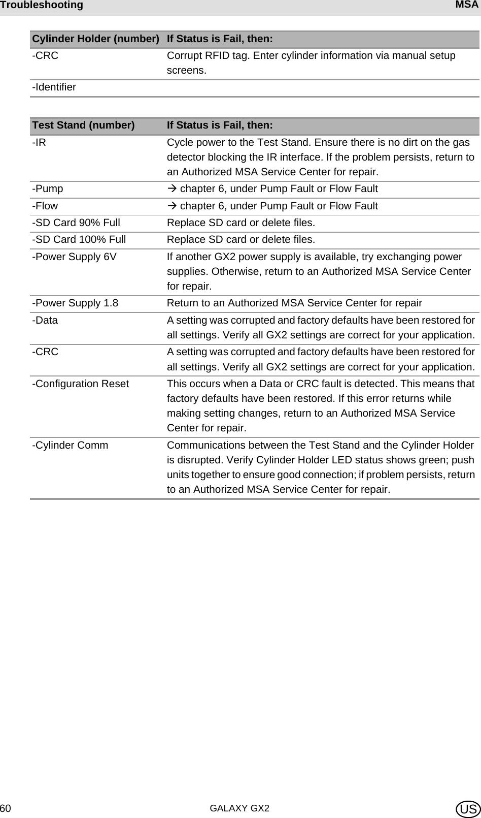
![MSA AUERMSA TroubleshootingGALAXY GX2 59US6.5 Cylinder Data Does Not DisplayIf using an electronic Cylinder Holder with RFID-tagged MSA gas cylinders, the general cylinder parameters automatically populate. If using a non-electronic Cylinder Holder or test gas from an independent source the user must manually enter cylinder data. Gas cylinder pressure will ONLY display with an electronic Cylinder Holder.Cylinder Data Does Not Display:(1) If using an electronic Cylinder Holder, verify the pressure is displayed on the Home screen. If not displayed, the Cylinder Holder and Test Stand may not be communicating via the con-nector. Remove the flange screws and push the two stands together. If a valid pressure read-ing displays re-insert the flange screws.(2) If using an electronic Cylinder Holder, ensure the test gas cylinder is properly screwed into the base.(3) If not using an RFID-tagged gas cylinder, verify that cylinder parameters have been entered [ GX2 Gas Setup].(4) Using an independent regulator, ensure the test cylinder(s) contain test gas.(5) If not using an electronic Cylinder Holder, ensure the cylinder description is entered in the cylinder set up screens. Refer to the cylinder configuration set up section [ chapter 4.7] of this manual. 6.6 Test Stand Yellow LED BlinkingThe Test Stand provides a comprehensive status of hardware and firmware components through the GX2 Status screen, accessed on the Administrator screen [ Fig. 23] by selecting the GX2 Status button. The table below shows the information reported for each Test Stand and Cylinder Holder in a bank. If one of these components is in Fault, a red message displays, indicating the error. The cylinder gauges on the Home screen and the subsequent cylinder screens only dis-play pressure, Part Number, Lot Number, and Expiration fields if using an electronic Cylinder Holder.Cylinder Holder (number) If Status is Fail, then:-Cylinder Gas Indicates a fault condition with the cylinder (expired or empty)-Flash Memory Return to an Authorized MSA Service Center for repair-RAM Memory Return to an Authorized MSA Service Center for repair-Power Supply 12V Return to an Authorized MSA Service Center for repair-Power Supply 6V If GX2 6V power supply shows failed, try reconnecting. Otherwise, return to an Authorized MSA Service Center for repair-RFID Tag Return to an Authorized MSA Service Center for repair-Communications Return to an Authorized MSA Service Center for repair- RFID Read Corrupt RFID tag. Enter cylinder information via manual setup screens.-Data Corrupt RFID tag. Enter cylinder information via manual setup screens.](https://usermanual.wiki/Mine-Safety-Appliances/10105756/User-Guide-1733964-Page-59.png)
![MSA AUERMSA TroubleshootingGALAXY GX2 61US6.7 System Error MessagesThe GALAXY GX2 can display a number of system errors that display on the Test Stand screen with a red error box. The error message must be acknowledged for Test Stand operations to resume.Memory Card Write ProtectOccurs if the memory card cannot accept data. Ensure the switch on the side of the memory card is unlocked so it can accept data.Serial Number RequiredOccurs when the instrument is missing its serial number. Use the free MSA Link software appli-cation and an IR dongle to assign a serial number to the instrument. A unique non-zero serial number is required for each gas detector model.Pump Fault or Flow FaultOccurs if pump(s) is blocked during a test, the test cylinder(s) read empty, the fresh air filter is clogged, or an internal flow error occurs. Visually inspect the air filter for contamination and re-place as needed. Refer to the Instrument Will Not Initiate a Bump or Calibration section [ chapter 6.1] of this manual.Partial TestThe test system lacks gases for a full test. Ensure the cylinder(s) configuration is set up correctly and that adequate gas is present in the cylinder(s). Refer to Cylinder Configuration section [ chapter 4.7] of this manual.USB Drive FailureOccurs if the user's flash drive cannot accept data. Ensure the flash drive is functioning properly. If the USB Drive is full, delete unneeded data or replace with a new USB Drive. Check the USB Drive Enable setting in the GALAXY GX2 Setup section [ chapter 4] of this manual.Network Connection LostOccurs if the optional network set up malfunctions. Ensure the Ethernet cables are secure between Test Stands, from the master unit to the PC, and that they are type 10/100 Mbps. Addi-tional information on network connections can be found in the software product end-user manual.](https://usermanual.wiki/Mine-Safety-Appliances/10105756/User-Guide-1733964-Page-61.png)
![MSA in Europe[ www.msa-europe.com & www.msa-gasdetection.com ]Northern Europe Southern Europe Eastern Europe Central EuropeNetherlandsMSA NederlandKernweg 201627 LH HoornPhone +31 [229] 25 03 03Fax +31 [229] 21 13 40info@msaned.nlBelgiumMSA BelgiumDuwijckstraat 172500 LierPhone +32 [3] 491 91 50Fax +32 [3] 491 91 51msabelgium@msa.beGreat BritainMSA BritainLochard HouseLinnet WayStrathclyde Business ParkBELLSHILL ML4 3RAScotlandPhone +44 [16 98] 57 33 57Fax +44 [16 98] 74 0141info@msabritain.co.ukSwedenMSA NORDICKopparbergsgatan 29214 44 MalmöPhone +46 [40] 699 07 70Fax +46 [40] 699 07 77info@msanordic.seMSA SORDINRörläggarvägen 833153 VärnamoPhone +46 [370] 69 35 50Fax +46 [370] 69 35 55info@sordin.seFranceMSA GALLETZone Industrielle Sud01400 Châtillon sur ChalaronnePhone +33 [474] 55 01 55Fax +33 [474] 55 47 99message@msa-gallet.frItalyMSA ItalianaVia Po 13/1720089 Rozzano [MI]Phone +39 [02] 89 217 1Fax +39 [02] 82 59 228info-italy@ msa-europe.comSpainMSA EspañolaNarcís Monturiol, 7Pol. Ind. del Sudoeste08960 Sant-Just Desvern[Barcelona]Phone +34 [93] 372 51 62Fax +34 [93] 372 66 57info@msa.esPolandMSA Safety Polandul. Wschodnia 5A05-090 Raszyn k/WarszawyPhone +48 [22] 711 50 33Fax +48 [22] 711 50 19eer@msa-europe.comCzech RepublicMSA Safety CzechPikartská 1337/7716 07 Ostrava-RadvanicePhone +420 [59] 6 232222Fax +420 [59] 6 232675info@msa-auer.czHungaryMSA Safety HungariaFrancia út 101143 BudapestPhone +36 [1] 251 34 88Fax +36 [1] 251 46 51info@msa.huRomaniaMSA Safety RomaniaStr. Virgil Madgearu, Nr. 5Ap. 2, Sector 1014135 BucurestiPhone +40 [21] 232 62 45Fax +40 [21] 232 87 23office@msanet.roRussiaMSA Safety RussiaPokhodny Proezd, 14 125373 MoscowPhone +7 [495] 921 1370/74Fax +7 [495] 921 1368msa-moscow@ msa-europe.comGermanyMSA AUER GmbHThiemannstrasse 112059 BerlinPhone +49 [30] 68 86 0Fax +49 [30] 68 86 15 17info@msa-auer.deAustriaMSA AUER Austria Vertriebs GmbHModecenterstrasse 22MGC Office 4, Top 601A-1030 Wien Phone +43 [0] 1 / 796 04 96Fax +43 [0] 1 / 796 04 96 - 20info@msa-auer.atSwitzerlandMSA SchweizEichweg 68154 OberglattPhone +41 [43] 255 89 00Fax +41 [43] 255 99 90info@msa.chEuropean International Sales[Africa, Asia, Australia, Latin America, Middle East]MSA EUROPEThiemannstrasse 112059 BerlinPhone +49 [30] 68 86 0Fax +49 [30] 68 86 15 58contact@msa-europe.com](https://usermanual.wiki/Mine-Safety-Appliances/10105756/User-Guide-1733964-Page-72.png)