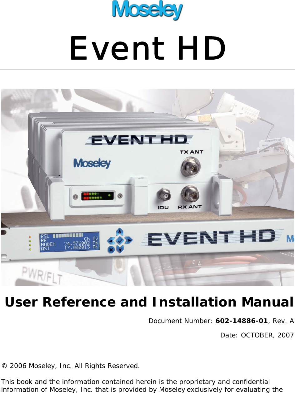
Moseley Associates EVENTHD ODU Event HD Outdoor Unit Digital Transceiver User Manual EVENT HD 080110hnf
Moseley Associates Inc ODU Event HD Outdoor Unit Digital Transceiver EVENT HD 080110hnf
UserManual.wiki
>
Moseley Associates
>
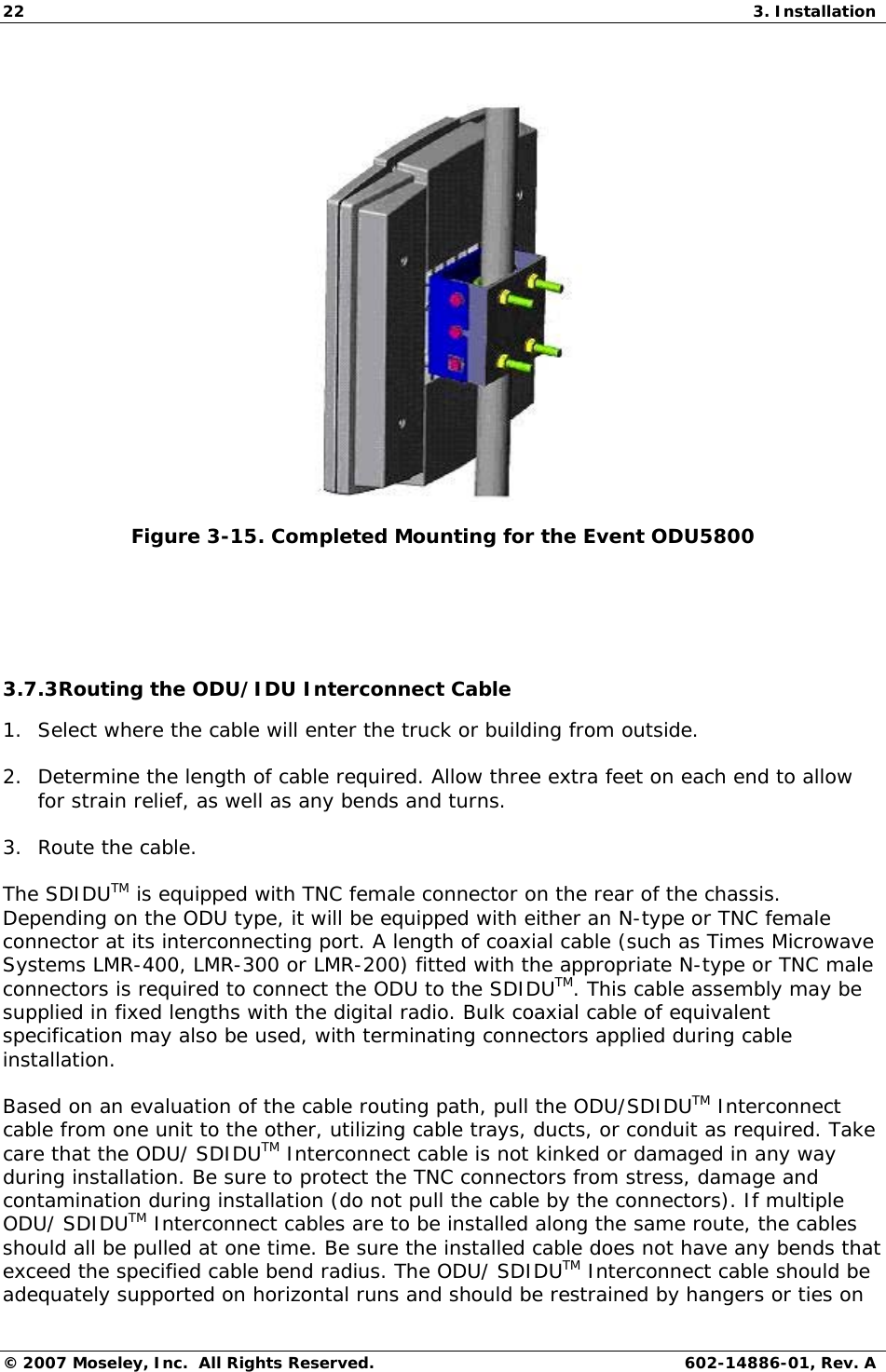
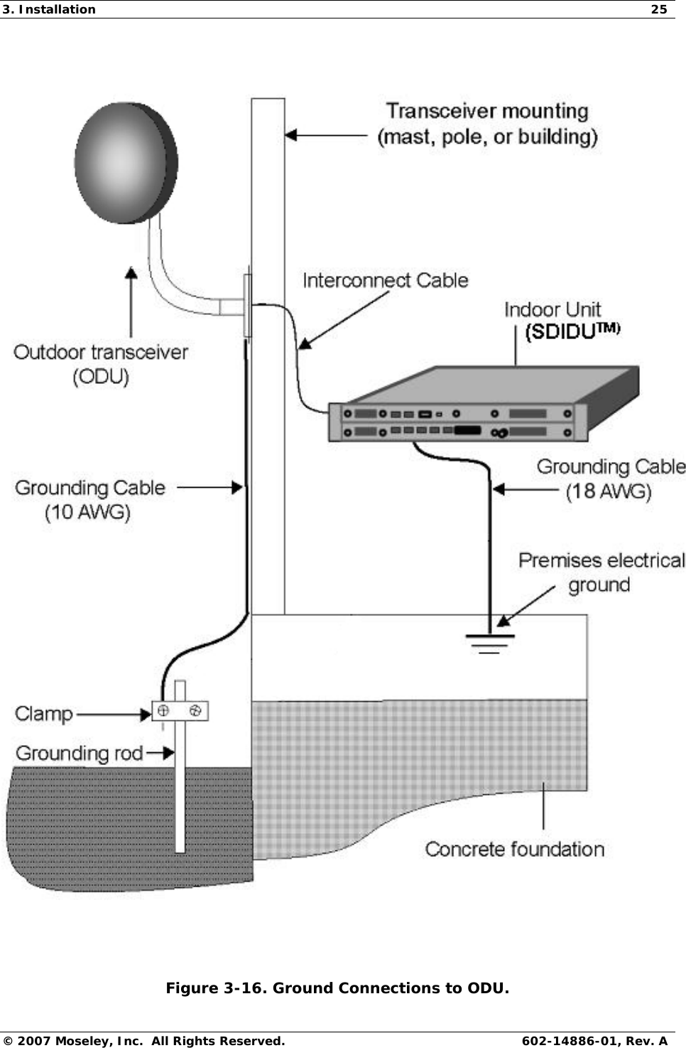
EVENTHD User Manual
>
Users Guide
Contents
1.
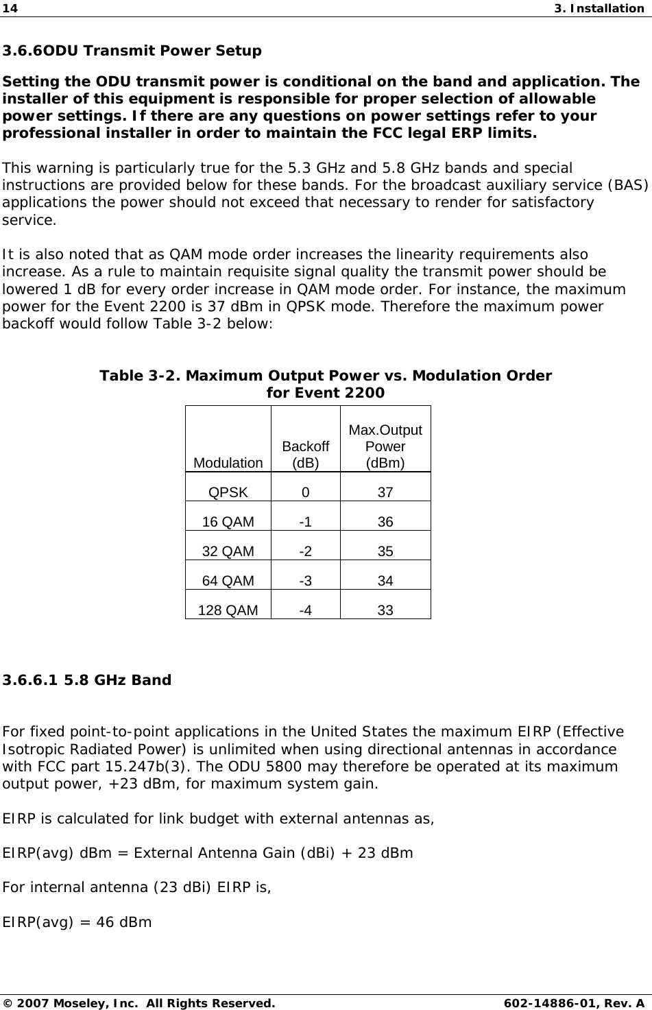
Users Manual
2.
Users Guide
Users Guide
Navigation menu
Upload a User Manual
Namespaces
Wiki Guide
HTML
PDF
Info
Views
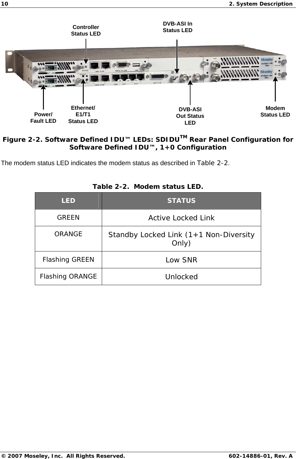
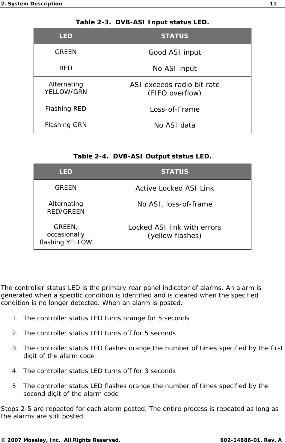
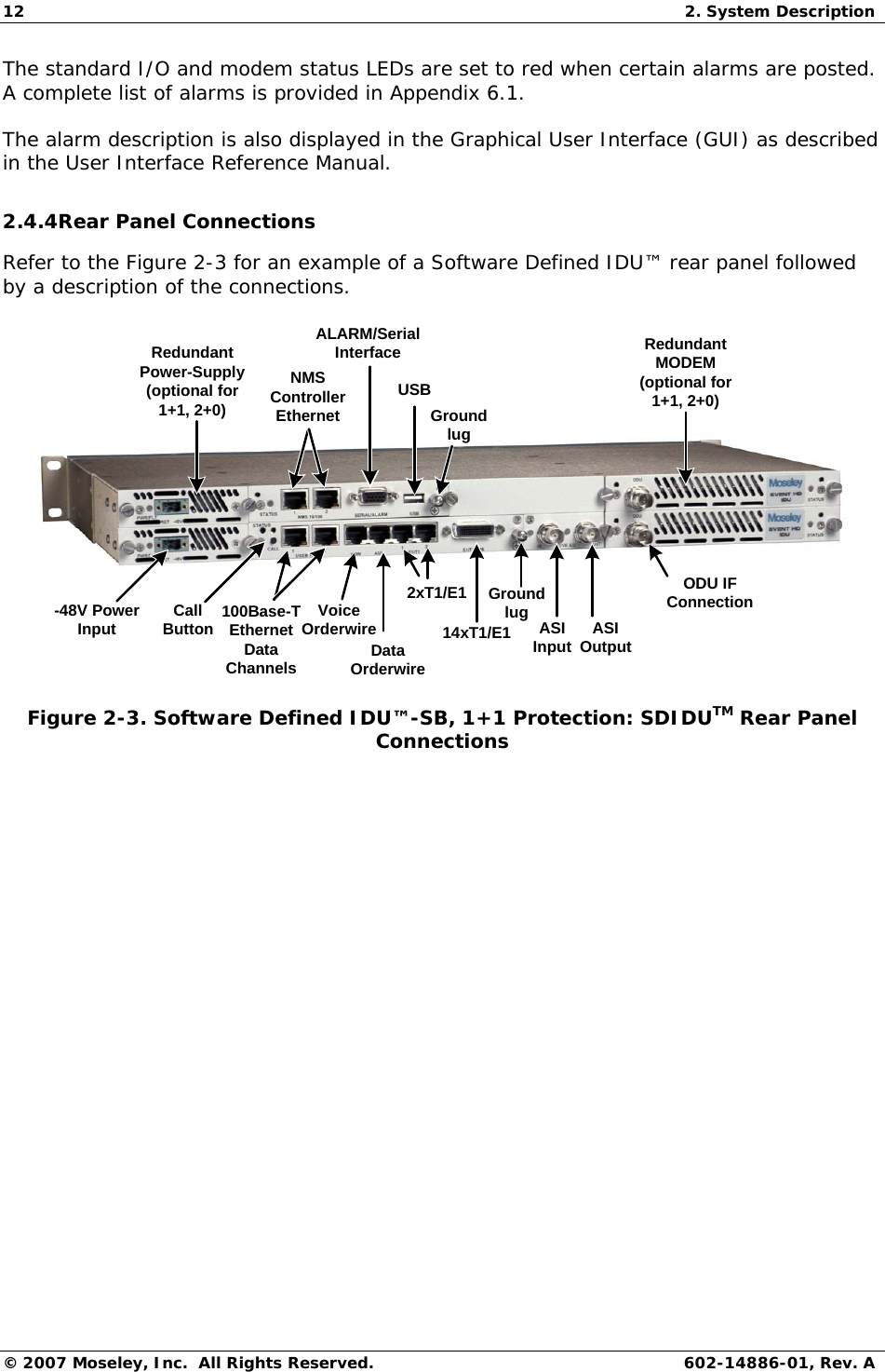
User Manual
Discussion / Help
Navigation