Moxa W2X50A Nport Device Server User Manual
Moxa Inc. Nport Device Server
UserManual.wiki
>
Moxa
>
W2X50A User Manual
>
user manual
Contents
1.
user manual
2.
Users Manual-1
3.
Users Manual-2
user manual
Navigation menu
Upload a User Manual
Namespaces
Wiki Guide
HTML
PDF
Info
Views
User Manual
Discussion / Help
Navigation

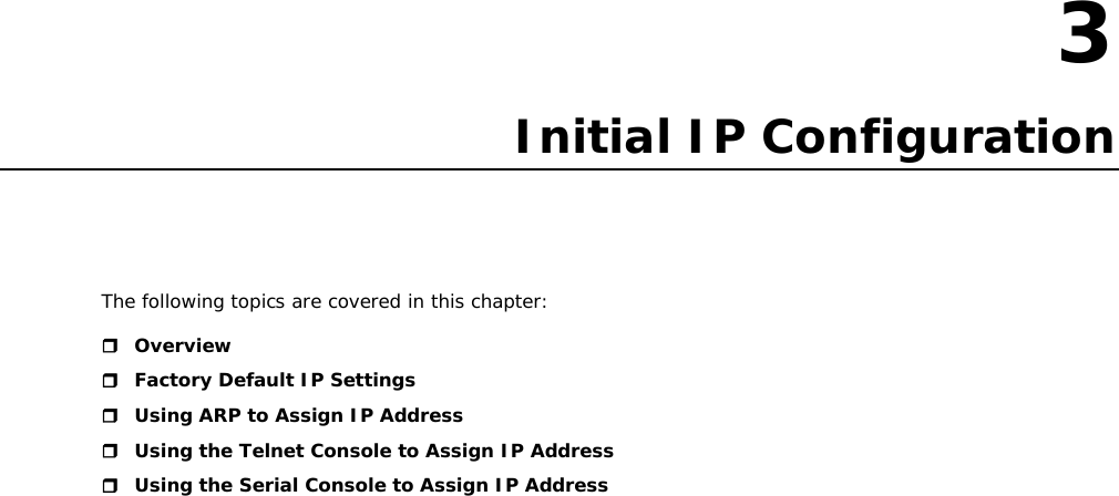
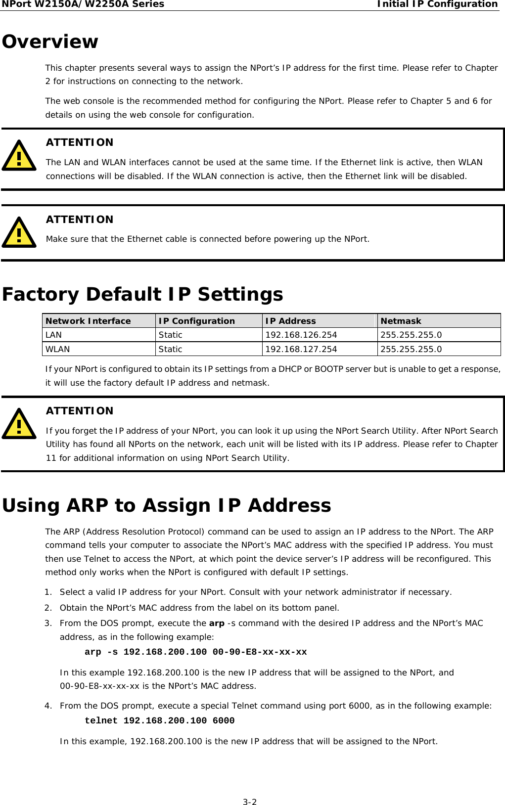
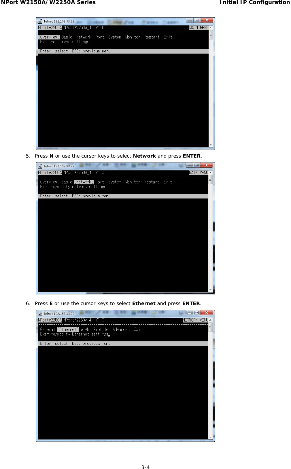
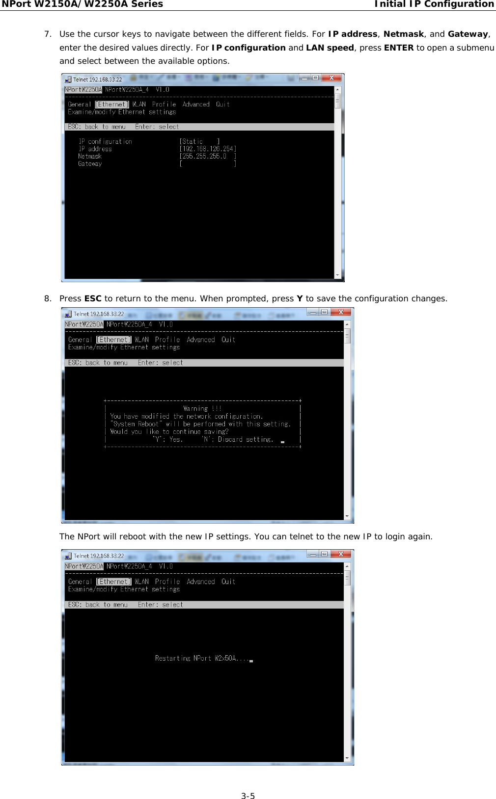
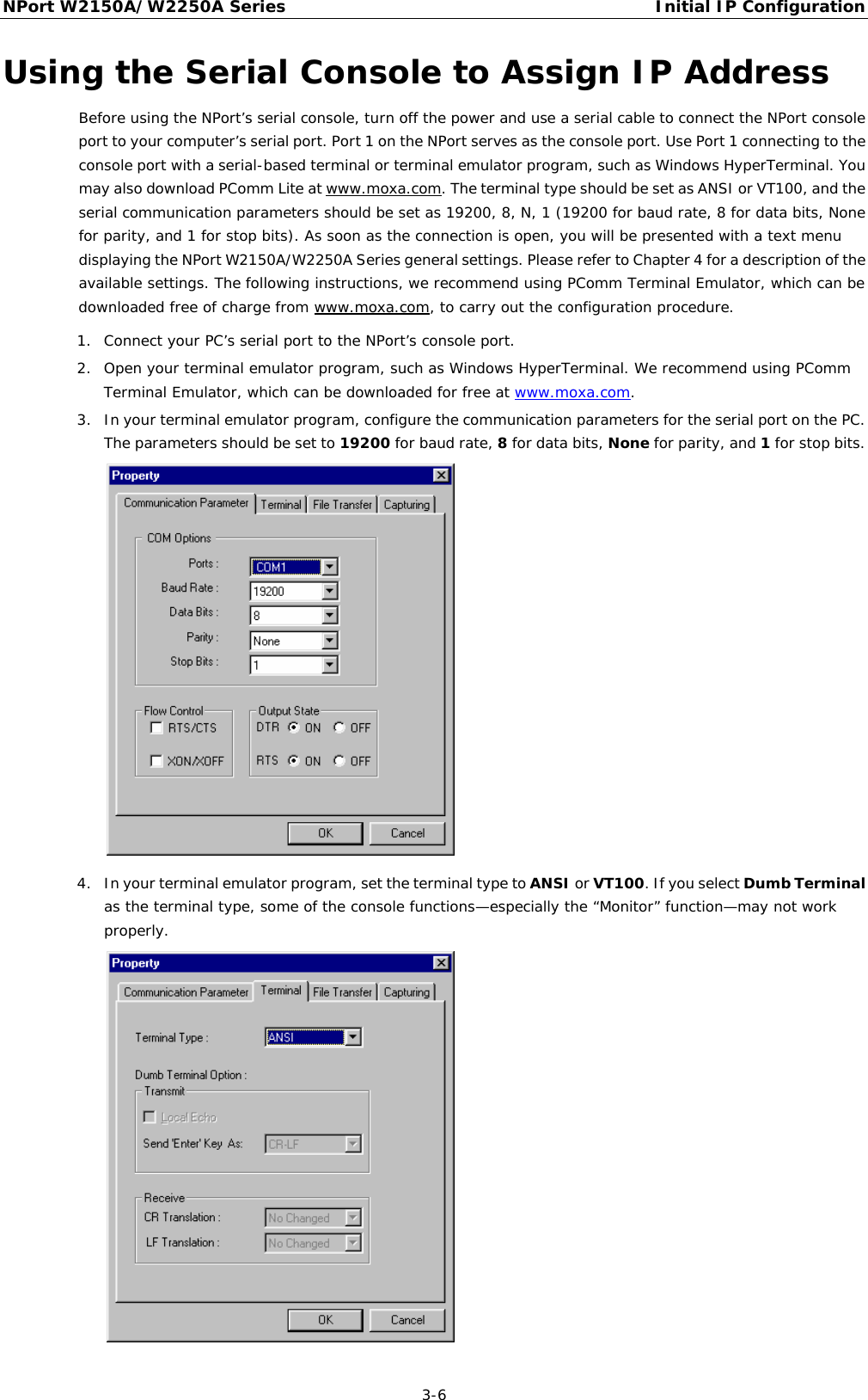
![NPort W2150A/W2250A Series Initial IP Configuration 3-3 5. You will see a message indicating that the connection failed. The NPort will automatically reboot with the new IP address. You can verify that the configuration was successful by connecting to the new IP address with Telnet, ping, the web console, or NPort Search Utility. Using the Telnet Console to Assign IP Address 1. Select Run… from the Windows Start menu. 2. Enter telnet 192.168.126.254 (the NPort’s default IP address) and click [OK]. 3. Enter your login account and password, then press ENTER. 4. You will login to the Overview page.](https://usermanual.wiki/Moxa/W2X50A.user-manual/User-Guide-1709701-Page-17.png)
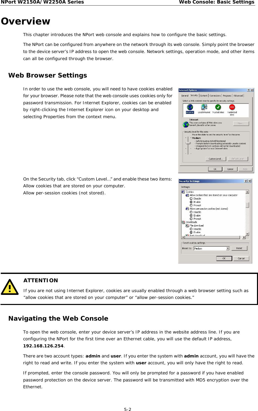
![NPort W2150A/W2250A Series Web Console: Basic Settings 5-3 ATTENTION If you have forgotten the password, you can use the reset button to load factory defaults, but this will erase all previous configuration information. The web console will appear as shown below. Settings are presented on pages that are organized by folder. Select the desired folder in the left navigation panel to open that page. The page will be displayed in the main window on the right. Certain folders can be expanded by clicking the adjacent “–” symbol. For example, if you click Basic Settings in the navigation panel, the main window will show a page of basic settings that you can configure. After you have made changes on a page, you must click [Submit] in the main window before jumping to another page. Your changes will be lost if you do not click [Submit].](https://usermanual.wiki/Moxa/W2X50A.user-manual/User-Guide-1709701-Page-28.png)
![NPort W2150A/W2250A Series Web Console: Basic Settings 5-4 Once you click [Submit] button, the device server will reboot and with a beep alarm. Basic Settings On the Basic Settings page, you can configure Server name, Server location, Time zone (24-hour), Local time, and Time server. Server Name Default NPortW2150A_<serial no.> or NPortW2250A_<serial no.> Options free text (e.g., “Server 1”) Description This is an optional free text field to help you differentiate one device server from another. It does not affect operation of the NPort device server. Server Location Default Options free text (e.g., “Bldg 1, 2nd Floor”) Description This is an optional free text field to help you differentiate one device server from another. It does not affect operation of the NPort device server. Time Zone Default (GMT)Greenwich Mean Time Options (GMT)Greenwich Mean Time (GMT-01:00)Azores, Cape Verde Is. (GMT-02:00)Mid-Atlantic etc. Description This field shows the currently selected time zone and allows you to select a different time zone.](https://usermanual.wiki/Moxa/W2X50A.user-manual/User-Guide-1709701-Page-29.png)
![NPort W2150A/W2250A Series Web Console: Basic Settings 5-5 Local Time Default Options Date (yy:mm:dd), Time (hh:mm:ss) Description The NPort has a built-in real-time clock that allows you to add time information to functions such as the automatic warning e-mail or SNMP trap. This field shows the current time according to the NPort’s built-in real-time clock. This is not a live field, so you will need to refresh the browser to get an updated reading. Change the correct date or time, and click [Submit]. The change will take effect directly, and shows Basic Setting OK!. ATTENTION There is a risk of explosion if the real-time clock battery is replaced incorrectly! The real time clock is powered by a lithium battery. We strongly recommend that you obtain assistance from a Moxa support engineer before replacing the battery. Please contact the Moxa RMA service team if you need to change the battery. Time Server Default Options IP address or domain name (e.g., “192.168.1.1” or “time.nist.gov”) Description This optional field specifies your time server’s IP address or domain name, if a time server is used in your network. The NPort supports SNTP (RFC-1769) for automatic time calibration. The device server will request time information from the specified time server every 10 minutes.](https://usermanual.wiki/Moxa/W2X50A.user-manual/User-Guide-1709701-Page-30.png)
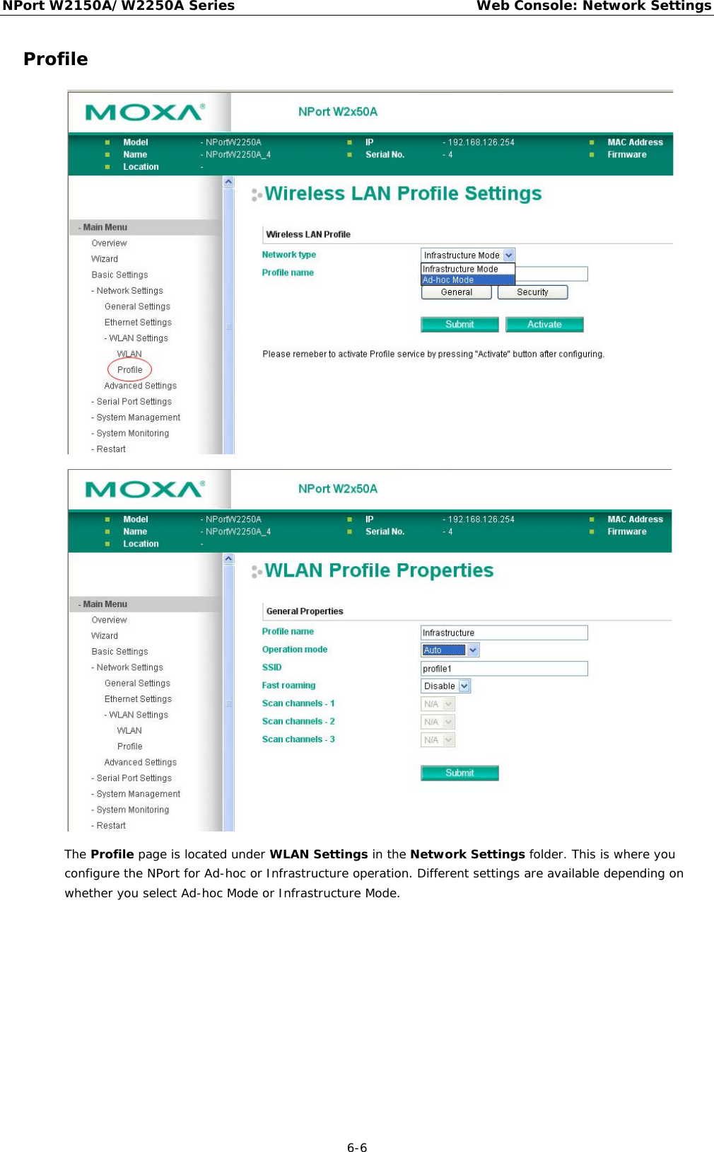
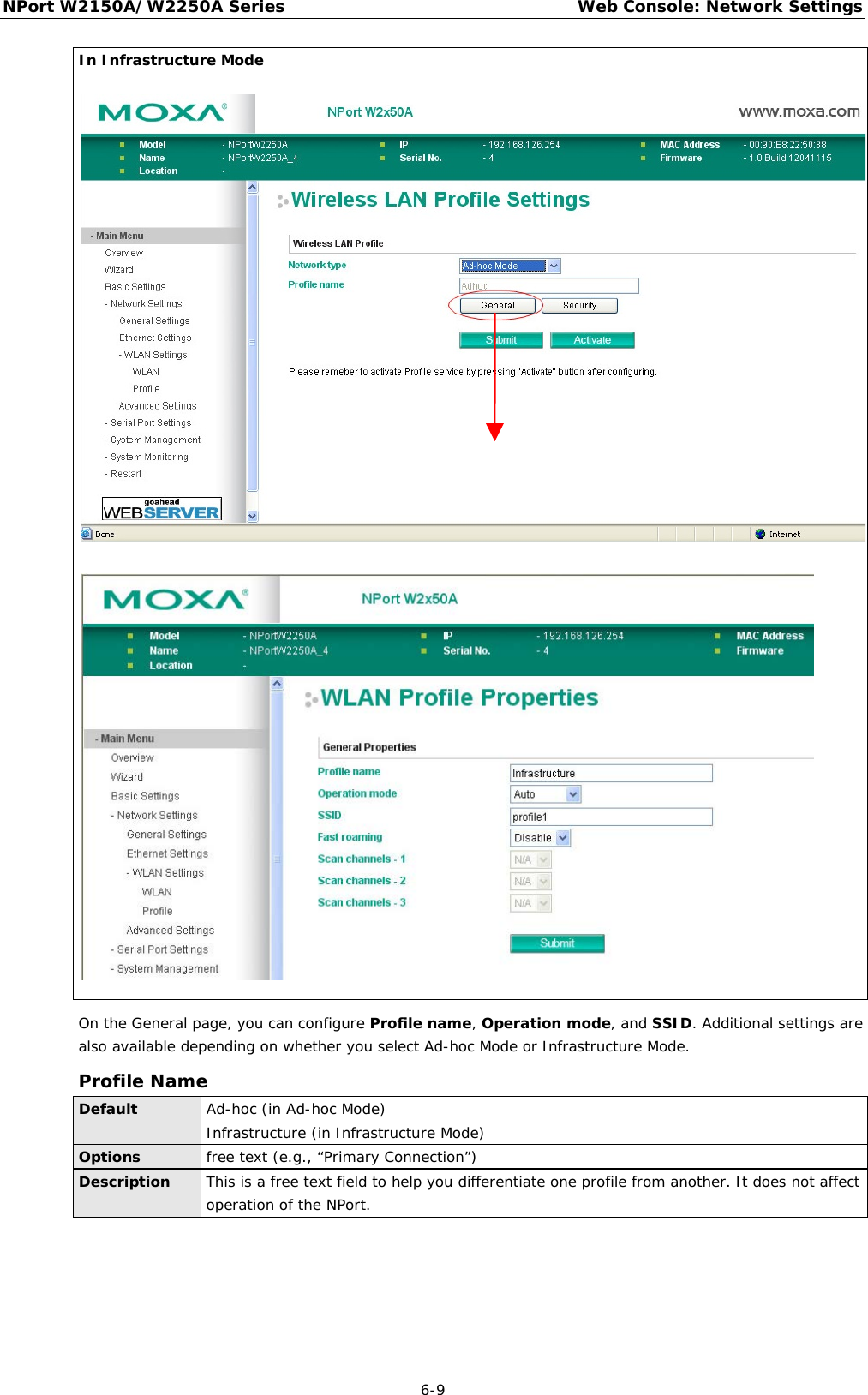
![NPort W2150A/W2250A Series Web Console: Network Settings 6-8 General Settings for WLAN Profile The General page is opened through the Profile page, under WLAN Settings in the Network Settings folder. You can type a profile name to help you differentiate one profile from another. It does not affect operation of the NPort. After selecting Ad-hoc or Infrastructure Mode, click [General] to open the General page for the selected profile. In Ad-hoc Mode and Infrastructure Mode, only one profile is available. In Ad-hoc Mode](https://usermanual.wiki/Moxa/W2X50A.user-manual/User-Guide-1709701-Page-38.png)
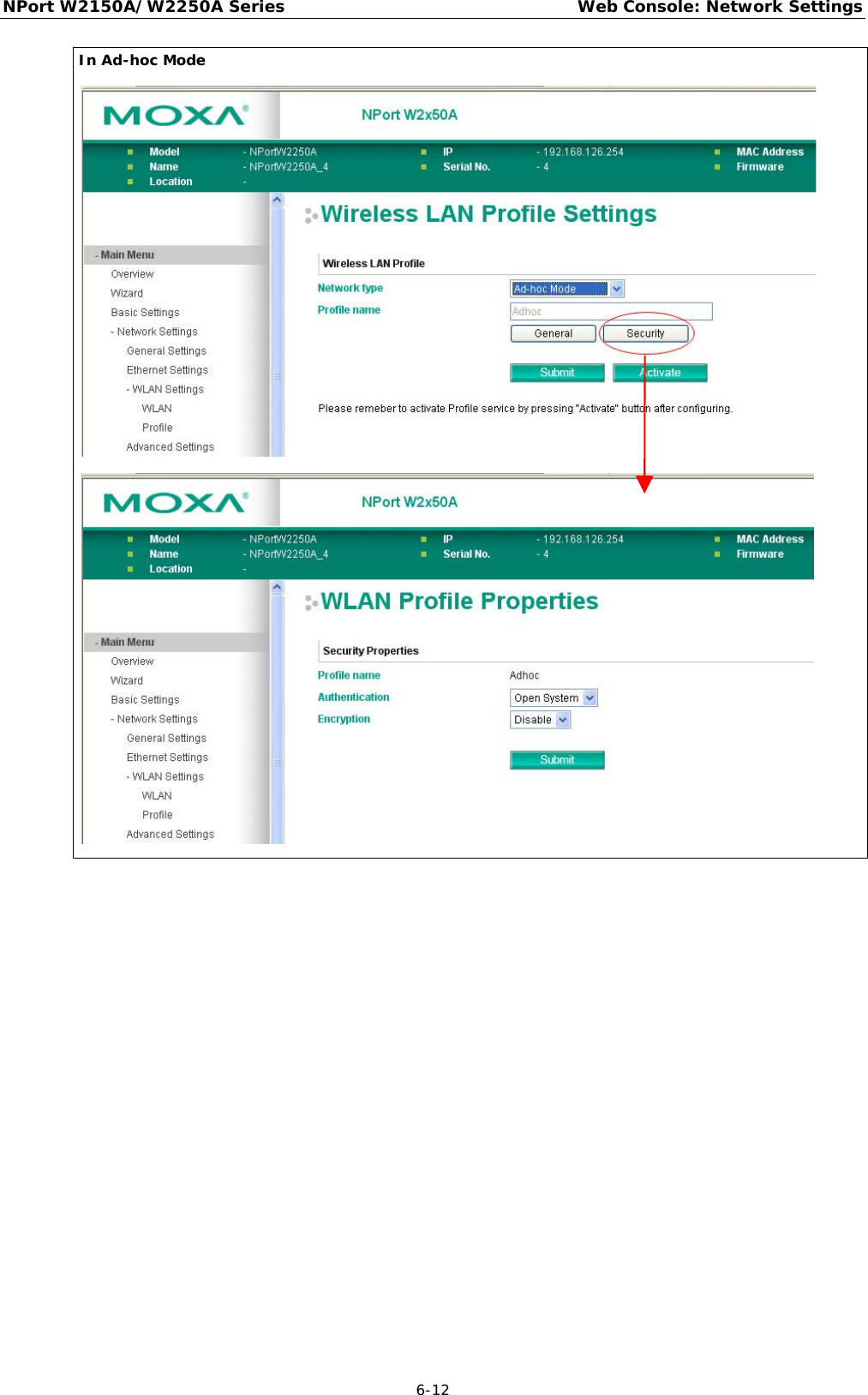
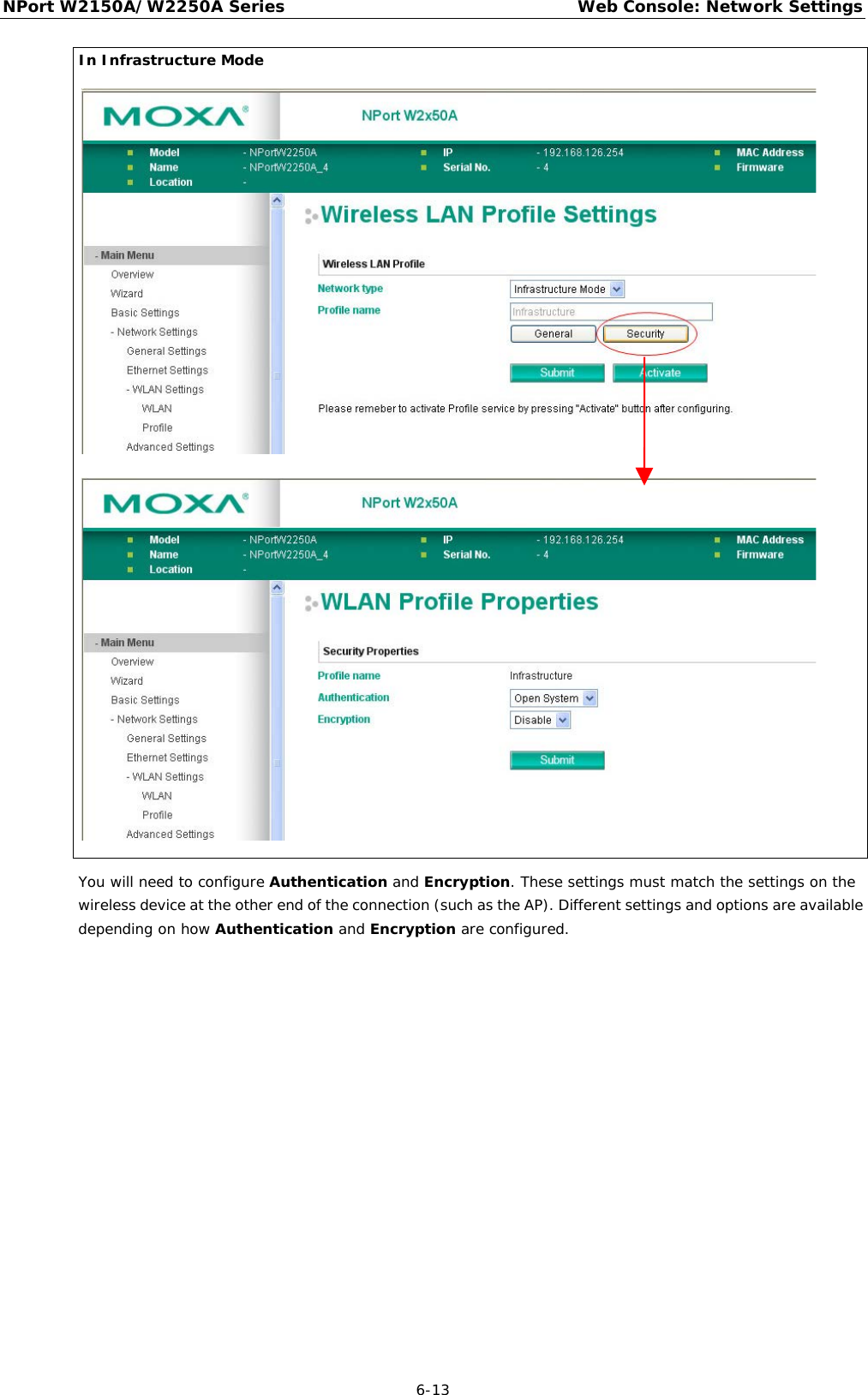
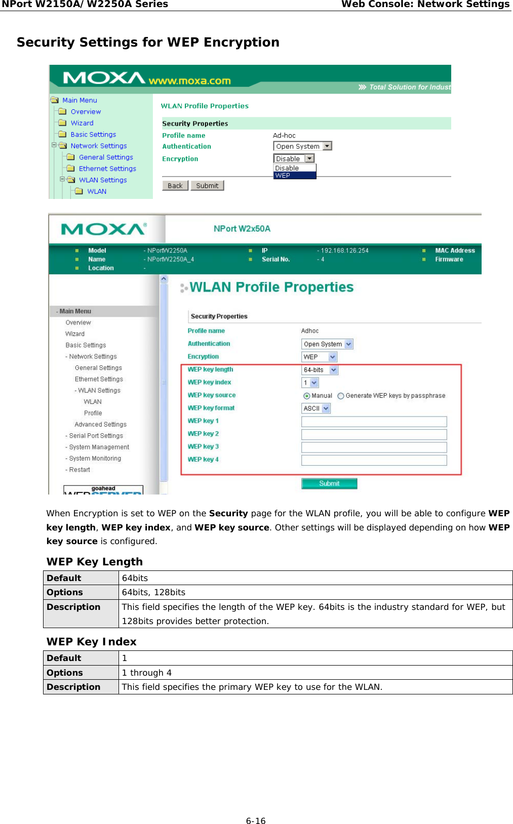
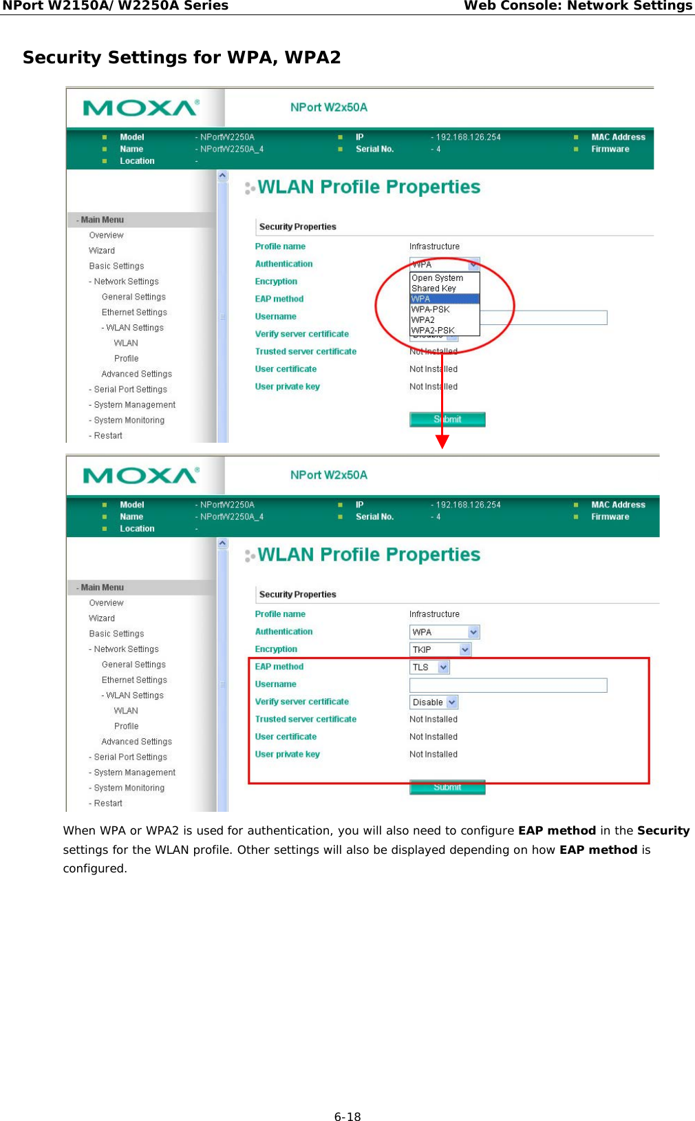
![NPort W2150A/W2250A Series Web Console: Network Settings 6-11 Fast Roaming (Infrastructure mode only) Default Disable Options Disable, Enable Description This field is only available in Infrastructure Mode and is used to specify the W2150A/W2250A roaming behavior. Roaming is the ability to connect to different APs so wireless communication is not confined to one area or one particular AP. The W2150A/W2250A will only roam between APs, as specified by the SSID. Disable: Fast Roaming function will be disabled. W2150A/W2250A will scan all available channels and roam between APs as specified by the SSID. It scans the channel when booting up and will associate with the highest signal strength AP. Only when the associated AP is loses, then it will re-associate again. Enable: Fast Roaming function will be enabled. NPort W2150A/W2250A will only scan the pre-defined "Scan Channels - 1, Scan Channels - 2 & Scan Channels – 3" and roam between APs as specified by the SSID. It scans the channel and will associate with the highest signal strength AP. It also scans the channel regularly and will re-associate with the highest signal strength AP (if there is) by automatically. Scan channels – 1, Scan channels – 2, Scan channels – 3 (Infrastructure mode only) Default N/A Options 1 through 14, 36, 40, 44, 48, 52, 56, 60, 64, 100, 104, 108, 112, 116, 120, 124, 128, 132, 136, 140, 149, 153, 157, 161 Description This field is for fast roaming under Infrastructure Mode and specifies the radio channel to use for the wireless network. Choose the channel according to the factory setting of AP. Security Settings for WLAN Profile The Security page is opened through the Profile page, under WLAN Settings in the Network Settings folder. After selecting Ad-hoc or Infrastructure Mode, click [Security] to open the Security page for the selected profile. In Ad-hoc Mode, only one profile is available, whereas three profiles are available in Infrastructure Mode.](https://usermanual.wiki/Moxa/W2X50A.user-manual/User-Guide-1709701-Page-41.png)

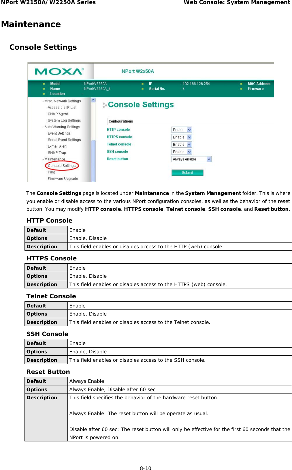
![NPort W2150A/W2250A Series Web Console: System Management 8-11 Maintenance Ping The Ping page is located under Maintenance in the System Management folder. It provides a convenient way to test an Ethernet connection or verify an IP address. Enter the IP address or domain name in the Destination field and click [Activate]. The results will be displayed immediately. Firmware Upgrade The Firmware Upgrade page is located under Maintenance in the System Management folder. This is where you can update the NPort firmware. After obtaining the latest firmware from www.moxa.com, select or browse for the firmware file in the Select firmware file field. Before clicking [Submit], it is a good idea to save the NPort configuration using the Configuration Export page, since the firmware upgrade process may cause all settings to revert to factory defaults.](https://usermanual.wiki/Moxa/W2X50A.user-manual/User-Guide-1709701-Page-86.png)
![NPort W2150A/W2250A Series Web Console: System Management 8-12 Configuration Import The Configuration Import page is located under Maintenance in the System Management folder. This is where you can load a previously saved or exported configuration. Select or browse for the configuration file in the Select configuration file field. If you also wish to import the IP configuration (i.e., IP address, netmask, and gateway), make sure that Import all configurations including IP configurations is checked. Configuration Export The Configuration Export page is located under Maintenance in the System Management folder. This is where you can save the NPort’s current configuration to a file on the local host. Click [Download] to begin the process. A window should appear asking you to open or save the configuration text file.](https://usermanual.wiki/Moxa/W2X50A.user-manual/User-Guide-1709701-Page-87.png)
![NPort W2150A/W2250A Series Web Console: System Management 8-13 Load Factory Default The Load Factory Default page is located under Maintenance in the System Management folder. Click [Submit] to reset all settings to the factory defaults. You can preserve the NPort’s existing IP settings (i.e., IP address, netmask, gateway, WLAN profile, and all certificates) by making sure Keep IP settings is checked before clicking [Submit]. Change Password The Change Password page is located under Maintenance in the System Management folder. To change the password, choose the account name first, and then enter the old password in the Old password field. Leave this blank if the NPort is not currently password-protected. Enter the new password twice, once in the New password field and once in the Confirm password. Leave these fields blank to remove password protection.](https://usermanual.wiki/Moxa/W2X50A.user-manual/User-Guide-1709701-Page-88.png)
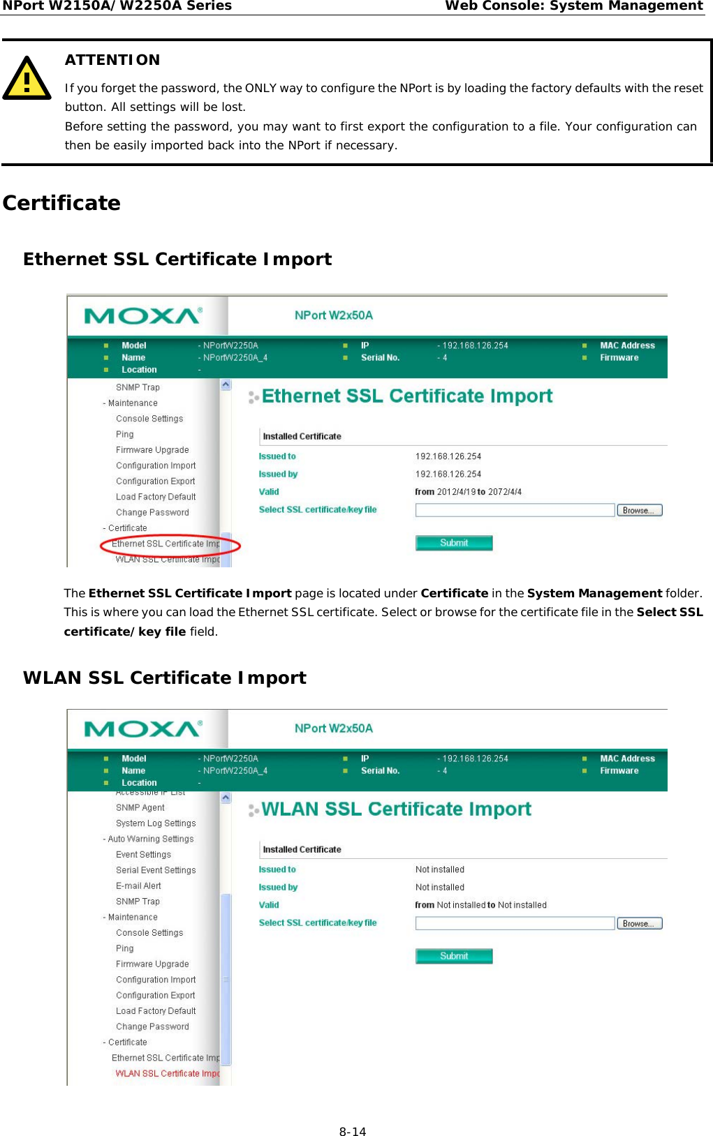
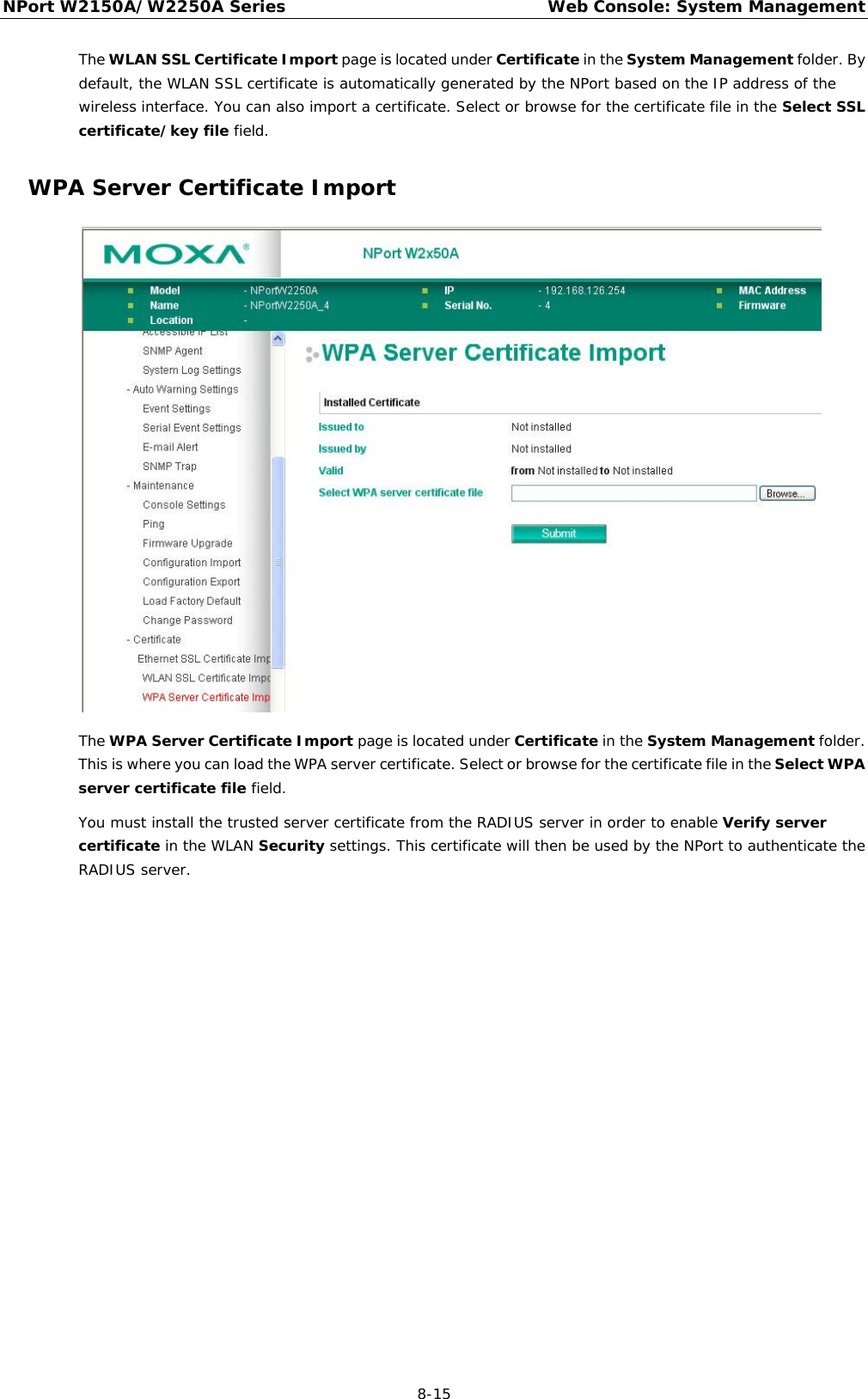
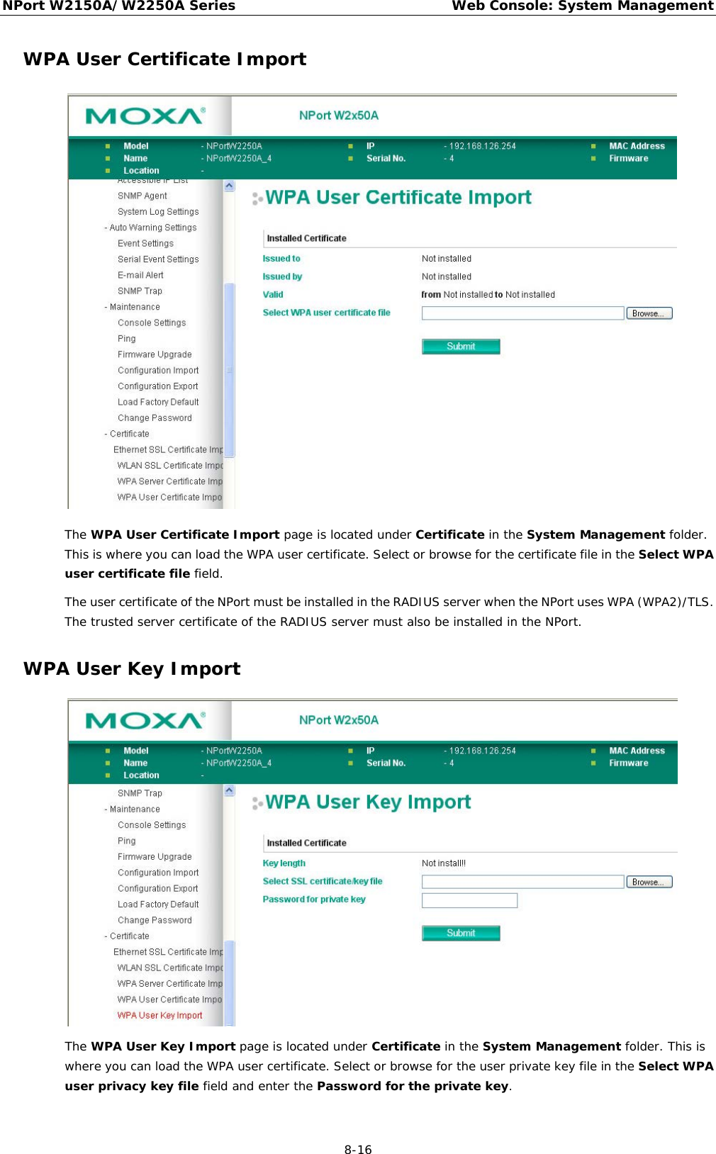
![NPort W2150A/W2250A Series Web Console: System Management 8-17 The user private key of the NPort must be installed in the RADIUS server when the NPort uses WPA(WPA2)//TLS. The trusted server certificate of RADIUS server must also be installed on the NPort. Certificate/Key Delete The Certificate/Key Delete page is located under Certificate in the System Management folder. This page is where you can delete certificates or WPA keys that have been installed on the model. When you click [Submit], any certificate or key that has been set to “Delete” will be deleted from the NPort.](https://usermanual.wiki/Moxa/W2X50A.user-manual/User-Guide-1709701-Page-92.png)
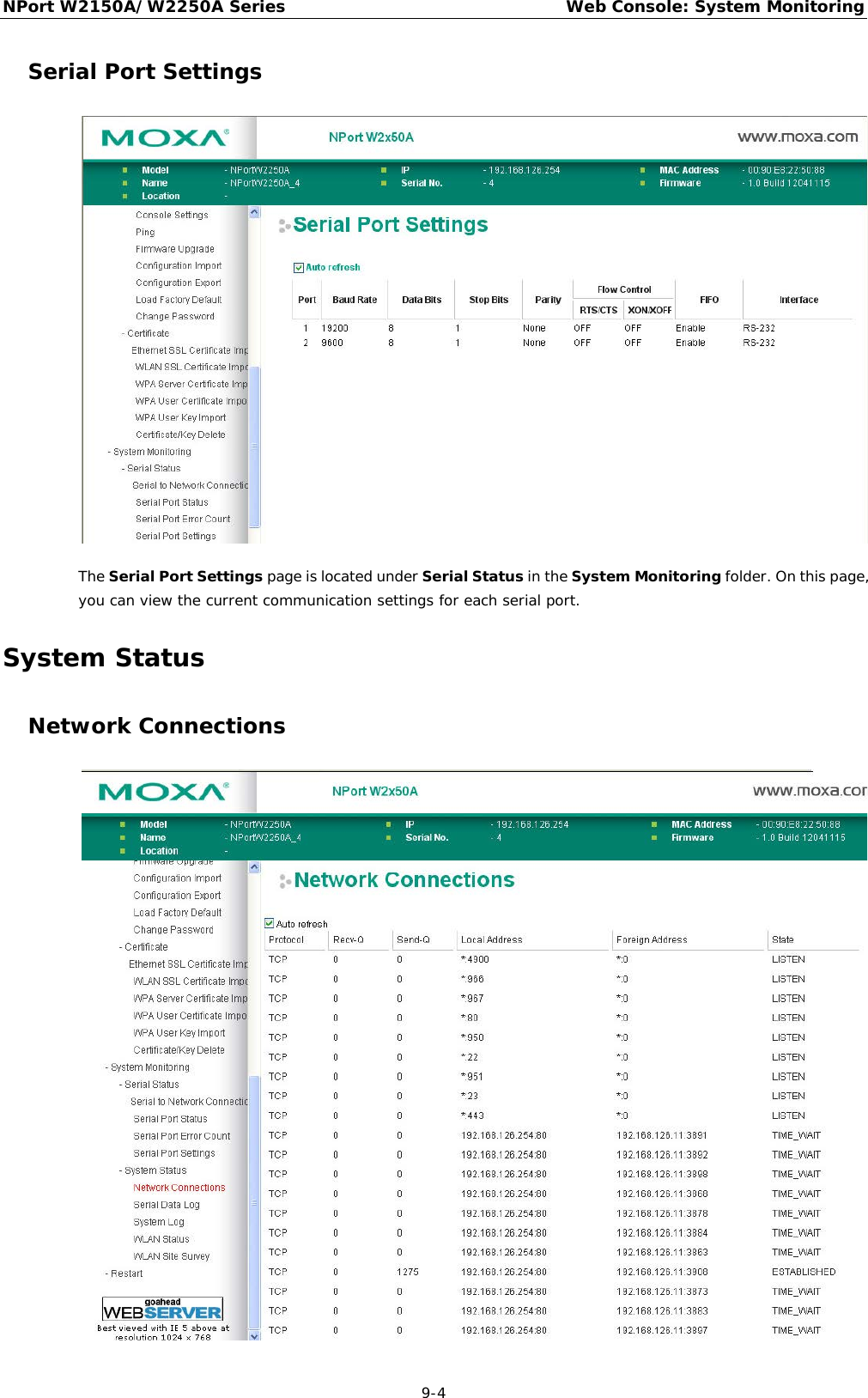
![NPort W2150A/W2250A Series Web Console: System Monitoring 9-5 The Network Connections page is located under System Status in the System Monitoring folder. On this page, you can view the current status of any network connection to the NPort. Serial Data Log Data logs for each serial port can be viewed in ASCII or HEX format. After selecting the serial port and format, you may click Select all to select the entire log if you wish to copy and paste the contents into a text file. The Clear log and Refresh buttons allow you to clear or refresh the log contents. The Serial Data Log page is located under System Status in the System Monitoring folder. This is where you can download the current data log for a serial port. Select the desired serial port in the Select port field. Select the desired data format in the Download format field. Click [Clear log] to clear the log contents. The data log includes all data sent or received by the specified serial port since the NPort was powered on. The maximum size of the log is 64 KB.](https://usermanual.wiki/Moxa/W2X50A.user-manual/User-Guide-1709701-Page-97.png)