Multitone Electronics PLC 2WREP EkoTek Repeater - 2 way radio repeater & beacon User Manual See relevant part
Multitone Electronics PLC EkoTek Repeater - 2 way radio repeater & beacon See relevant part
UserManual.wiki
>
Multitone Electronics PLC
>
2WREP User Manual
See relevant part
Navigation menu
Upload a User Manual
Namespaces
Wiki Guide
HTML
PDF
Info
Views
User Manual
Discussion / Help
Navigation
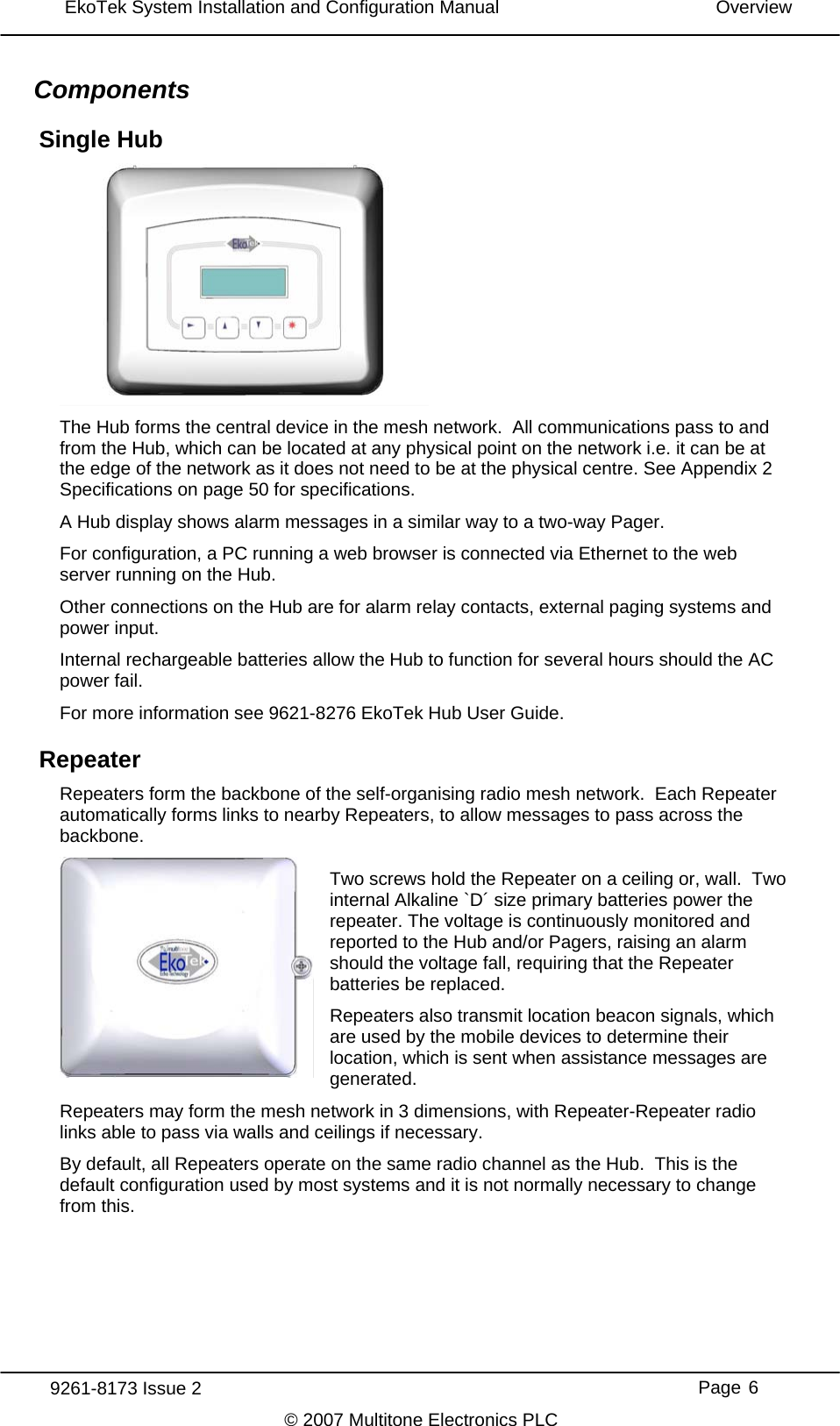
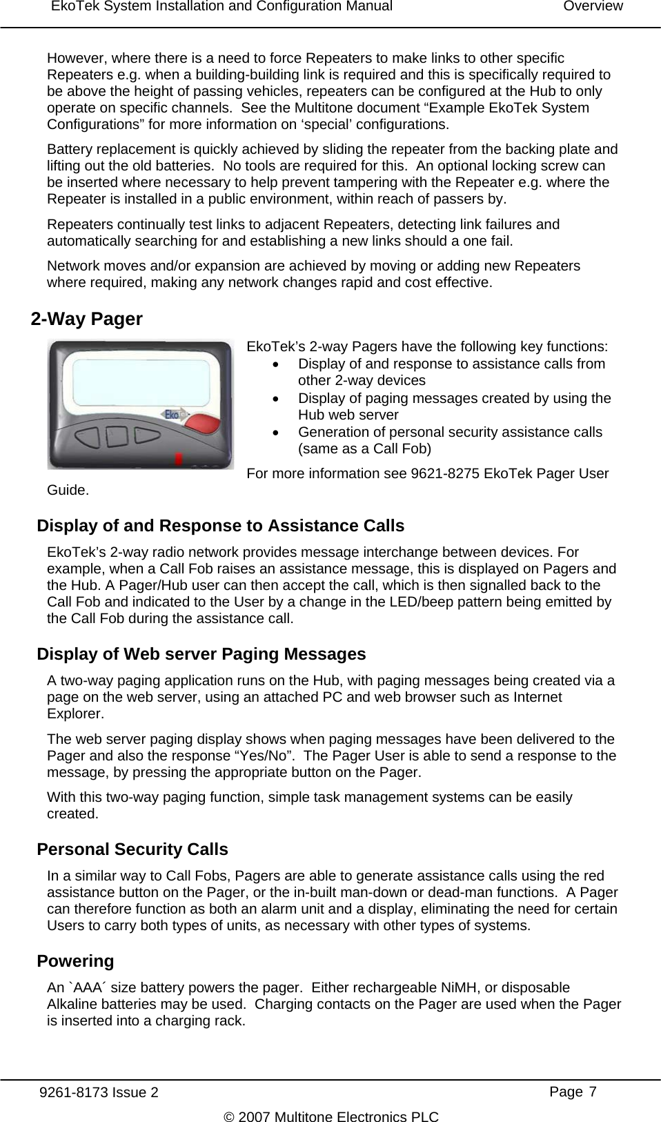
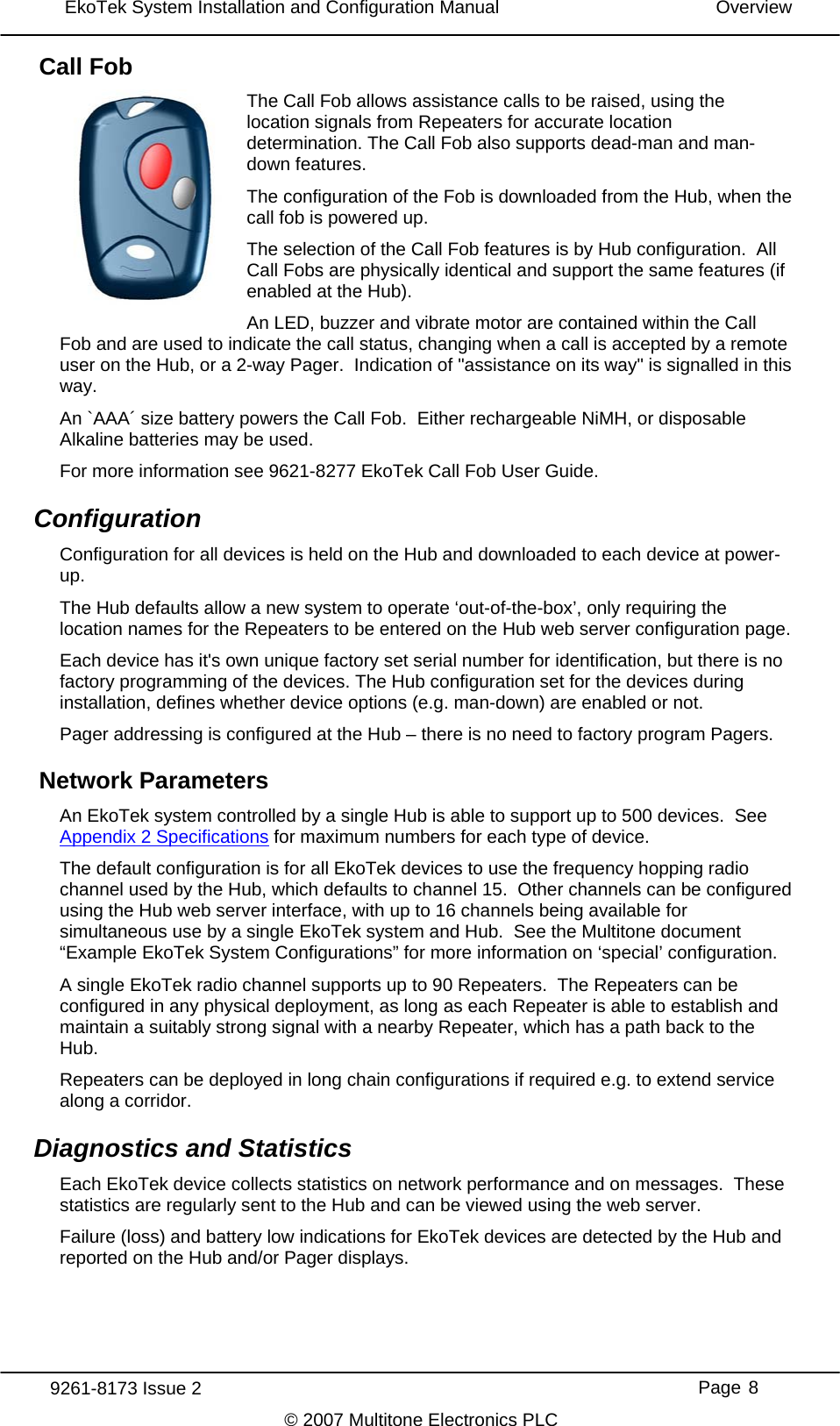
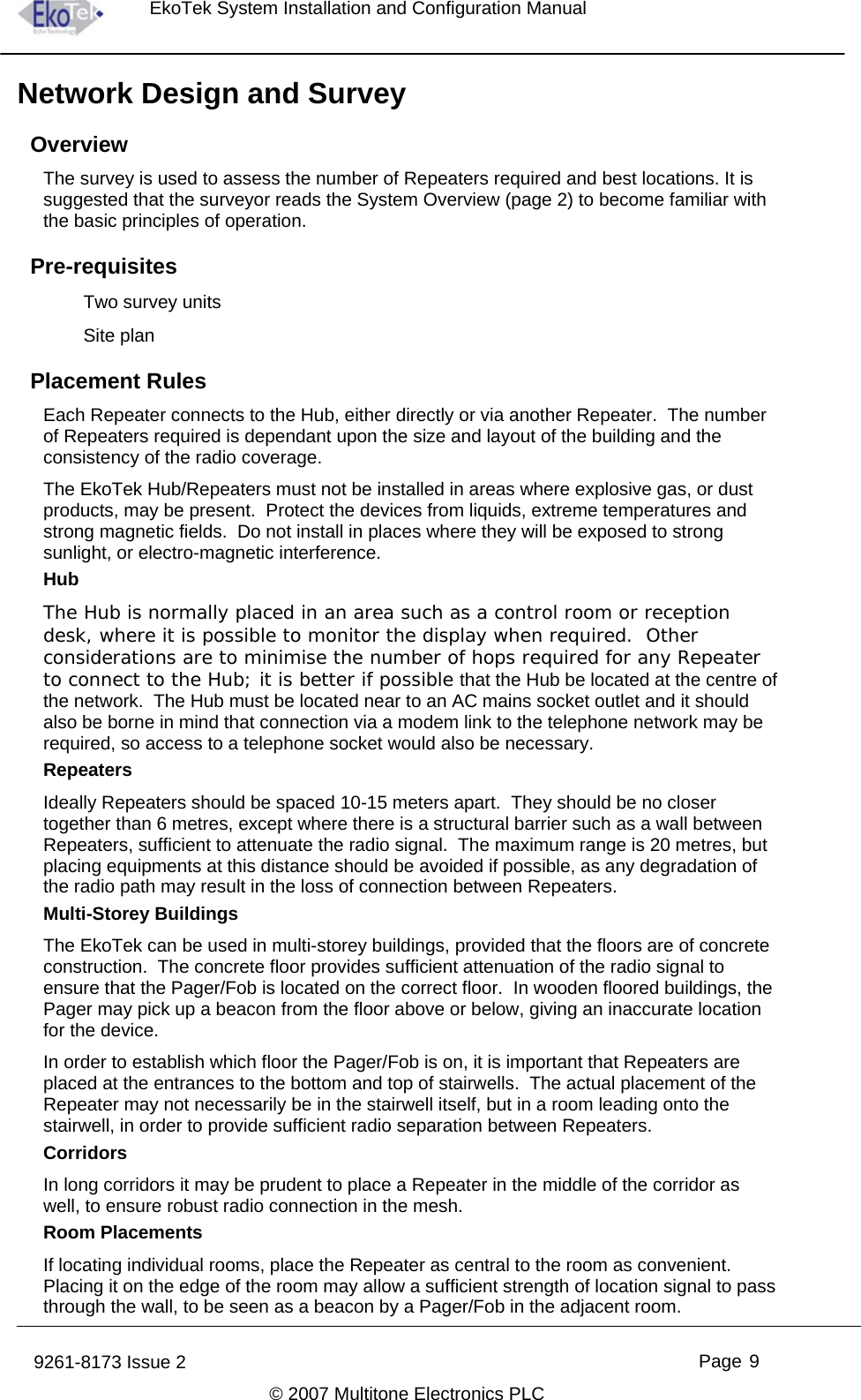
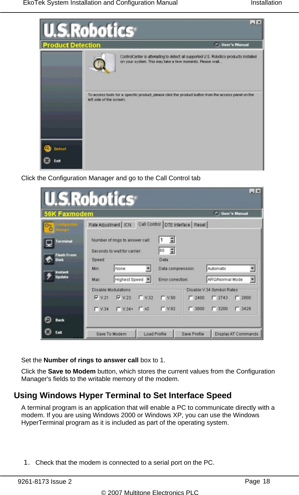
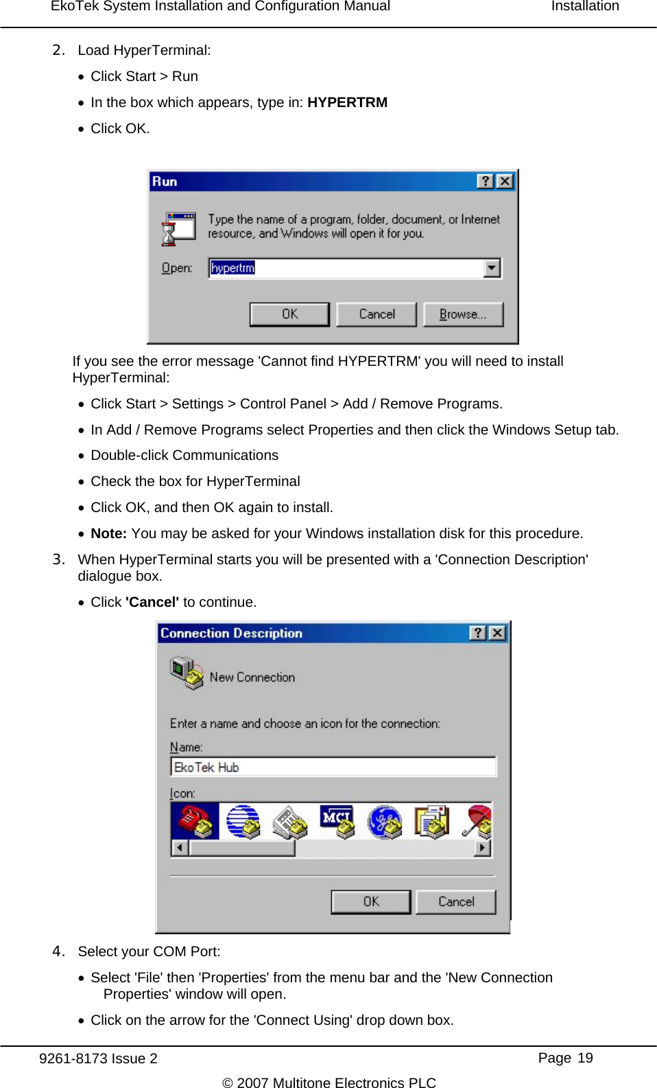
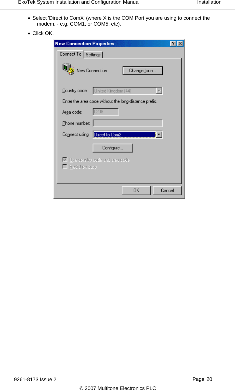
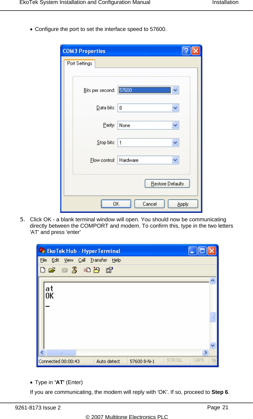
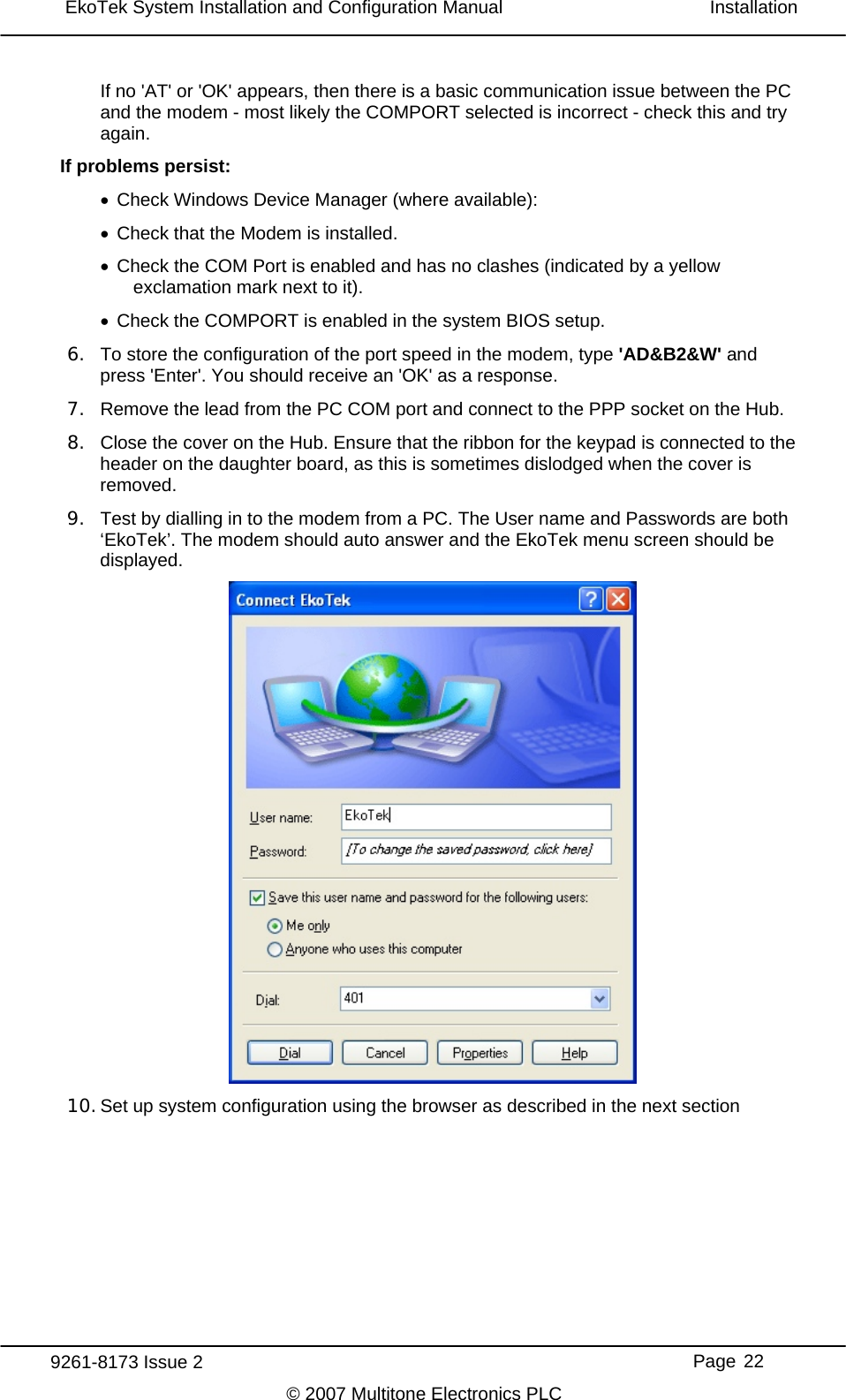
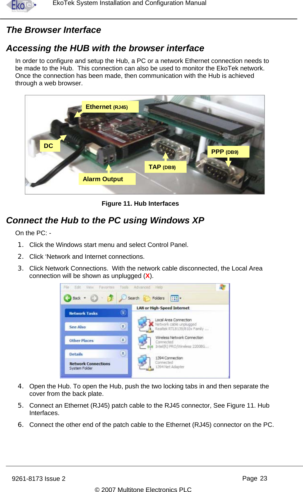
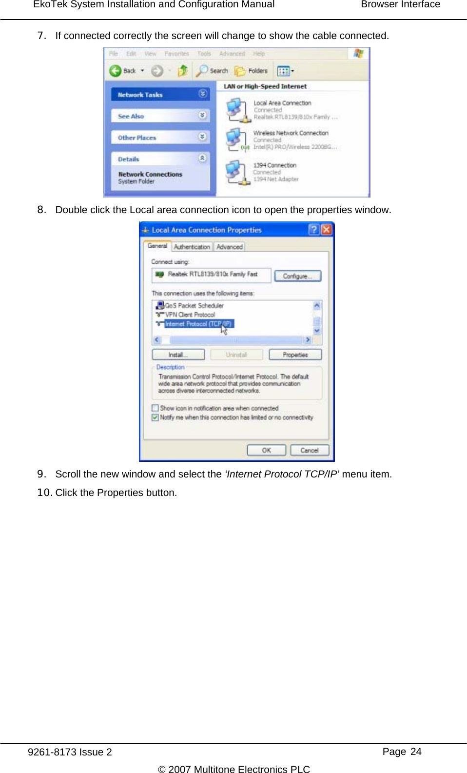
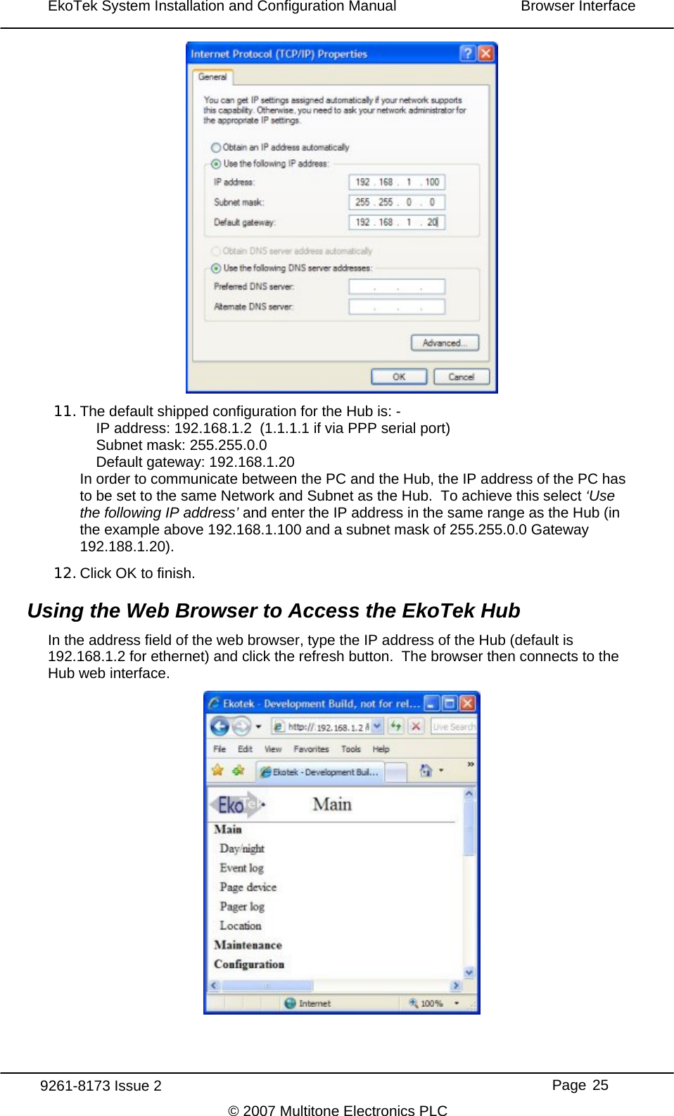
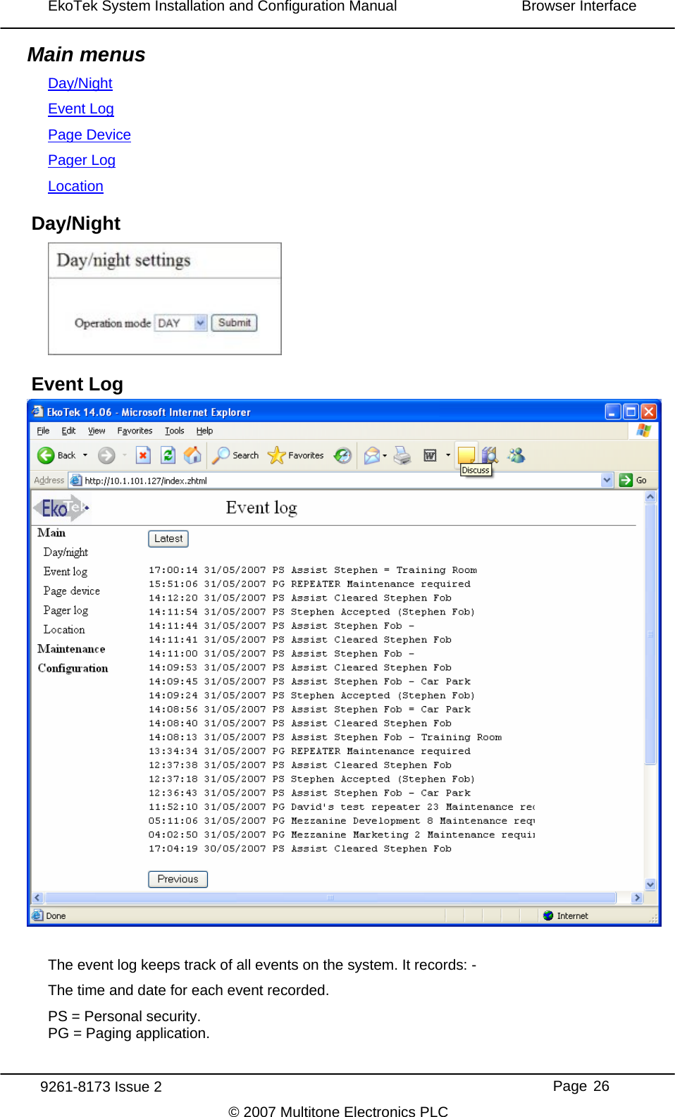
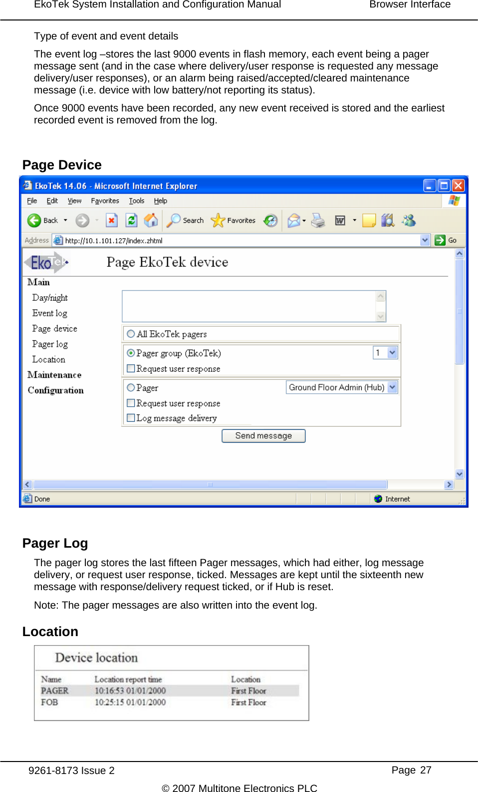
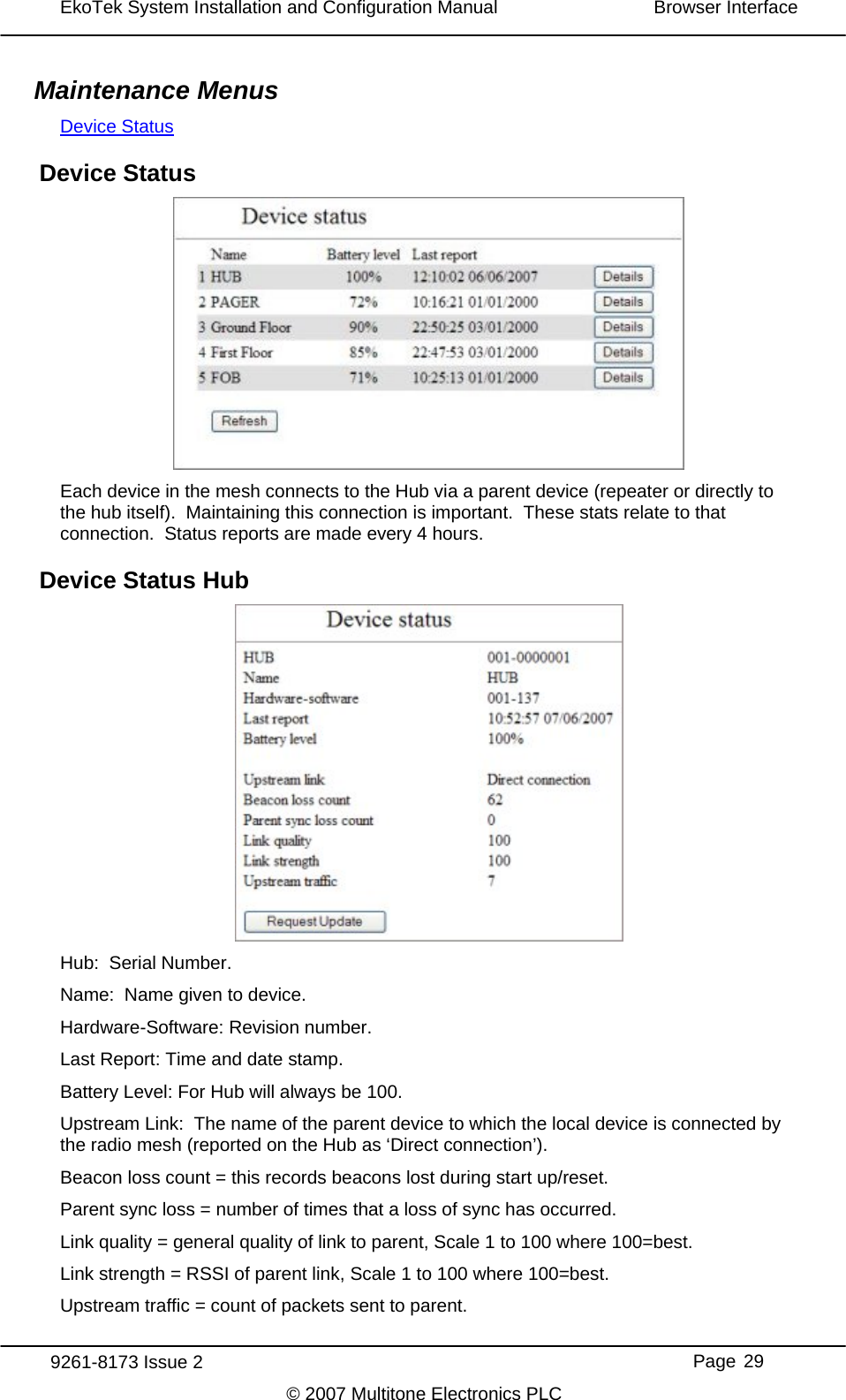
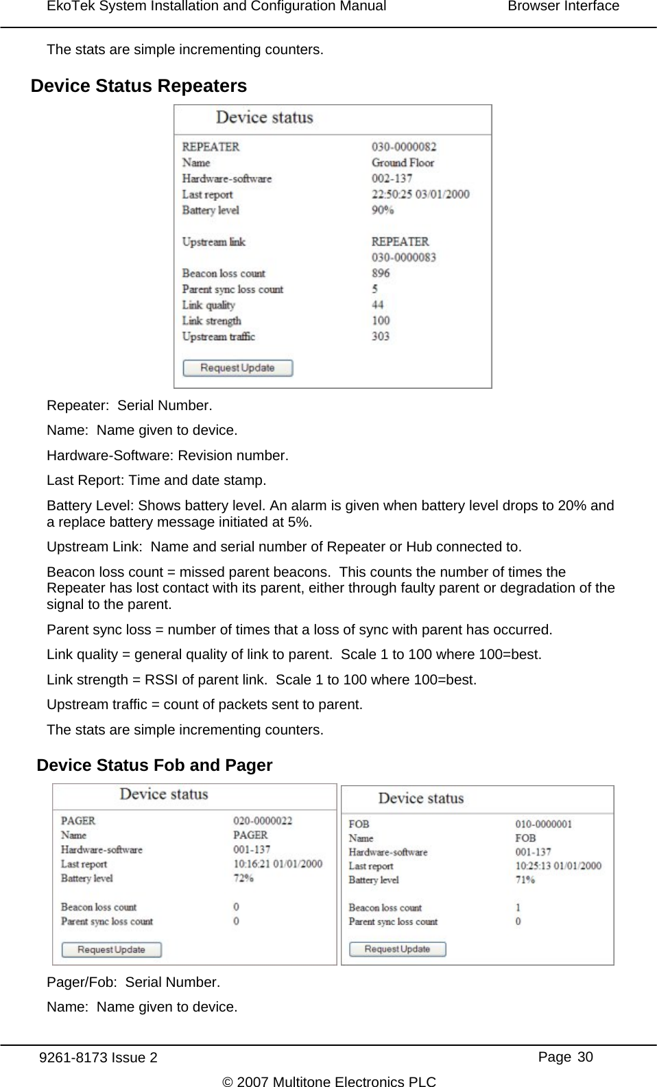
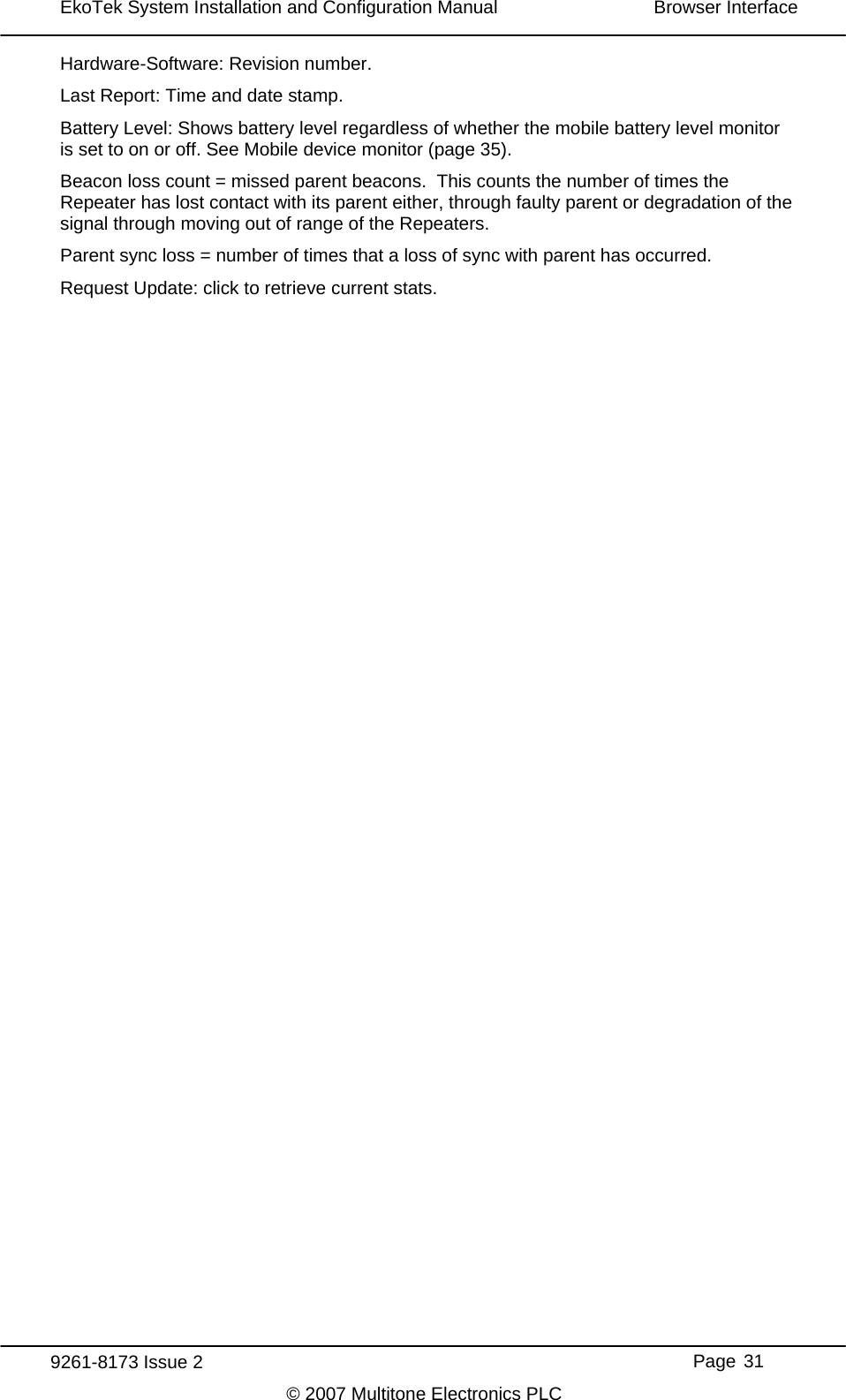
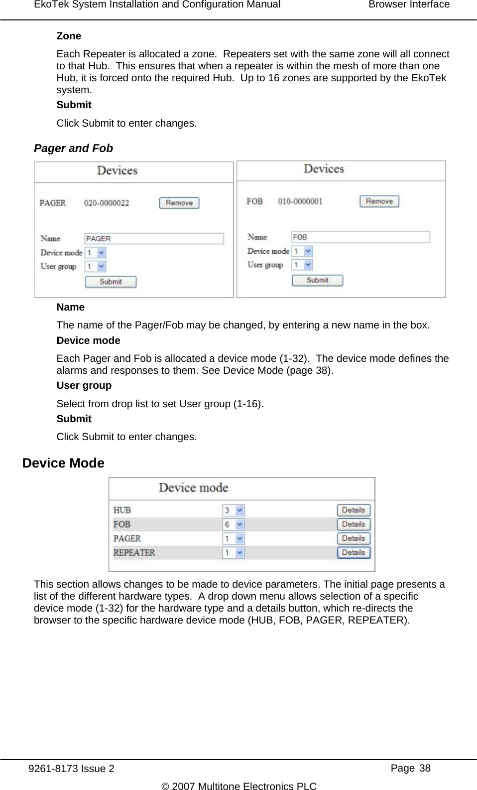
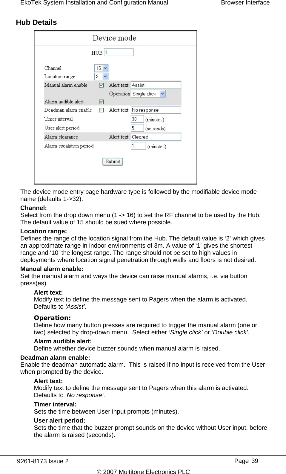
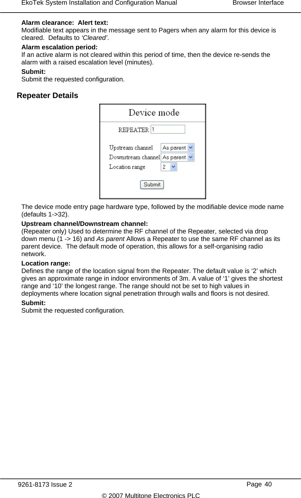
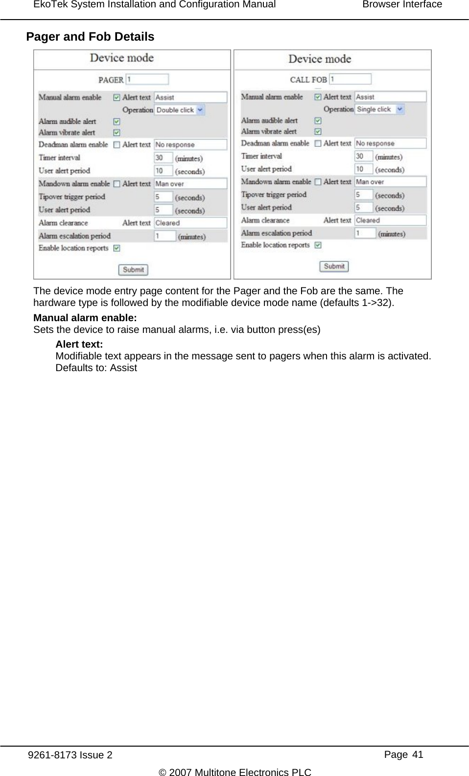
![EkoTek System Installation and Configuration Manual Overview When a user signals an alarm, the user identification (name), location and alarm type are included in the alarm message displayed on the Hub and sent to Pagers. Beacons Beacon signals are used to update a device with information of whom its parent is. A Repeater/Pager/Fob can only ever have one parent at a time. Every 1000ms the Repeater transmits to the Pager/Fob, which is then updated with its location and will continue to receive subsequent beacons from the Repeater (its parent). It will be shown as ‘= [location name]’ on the Pager's display. As the User moves from one Repeater towards another, they will receive a handover beacon from the Repeater being approached. The Pager then displays ‘- [location name]’. The Pager/Fob then picks up location information from the new Repeater and updates itself with the new location. Two-Way Acknowledgement For peace of mind of the User, the acceptance of an alarm at the Hub or a two-way Pager by someone who will be going to the aid of the User, is signalled back to the User by the Call Fob lamp and beeper changing their alert patterns. Two-Way Radio All EkoTek radio links are two-way, providing the ability to signal both to and from all devices on the network. Two-way radio provides the ability to quickly detect and correct any lost messages e.g. when a message is relayed from one Repeater to a second Repeater, the second Repeater will acknowledge receipt of the message. If the first Repeater does not receive an acknowledgement, it retransmits the message. This ability allows EkoTek to function, even in environments where there is radio interference or poor signal. A further benefit of two-way radio is the ability to download configuration parameters to all devices from the Hub, using over air programming. Devices do not hold their own configuration, as this is sent by the Hub upon request, when devices are powered up. Hence even Pagers have their configuration held at the Hub, making it unnecessary to recall mobile devices for configuration change, as any updates are made centrally at the Hub. Frequency Hopping EkoTek radio links can be configured to operate on a fixed frequency, or to hop across all 16 available frequencies. Frequency hopping increases the immunity of EkoTek systems to radio interference. If a message is lost due to interference on a frequency, the loss is immediately detected and the message retransmitted on the next frequency in the hopping sequence. Frequency hopping is especially useful where the local radio environment may be unknown, or subject to change. EkoTek’s combination of message loss detection, automatic message retransmission and frequency hopping, makes for a very robust radio infrastructure. 9261-8173 Issue 2 Page 5 © 2007 Multitone Electronics PLC](https://usermanual.wiki/Multitone-Electronics-PLC/2WREP/User-Guide-839498-Page-9.png)