NETSCOUT Systems OPTIVIEW-XG Local Area Network Test and Diagnostic Test Equipment User Manual OptiView XG GSG
Fluke Networks Local Area Network Test and Diagnostic Test Equipment OptiView XG GSG
Contents
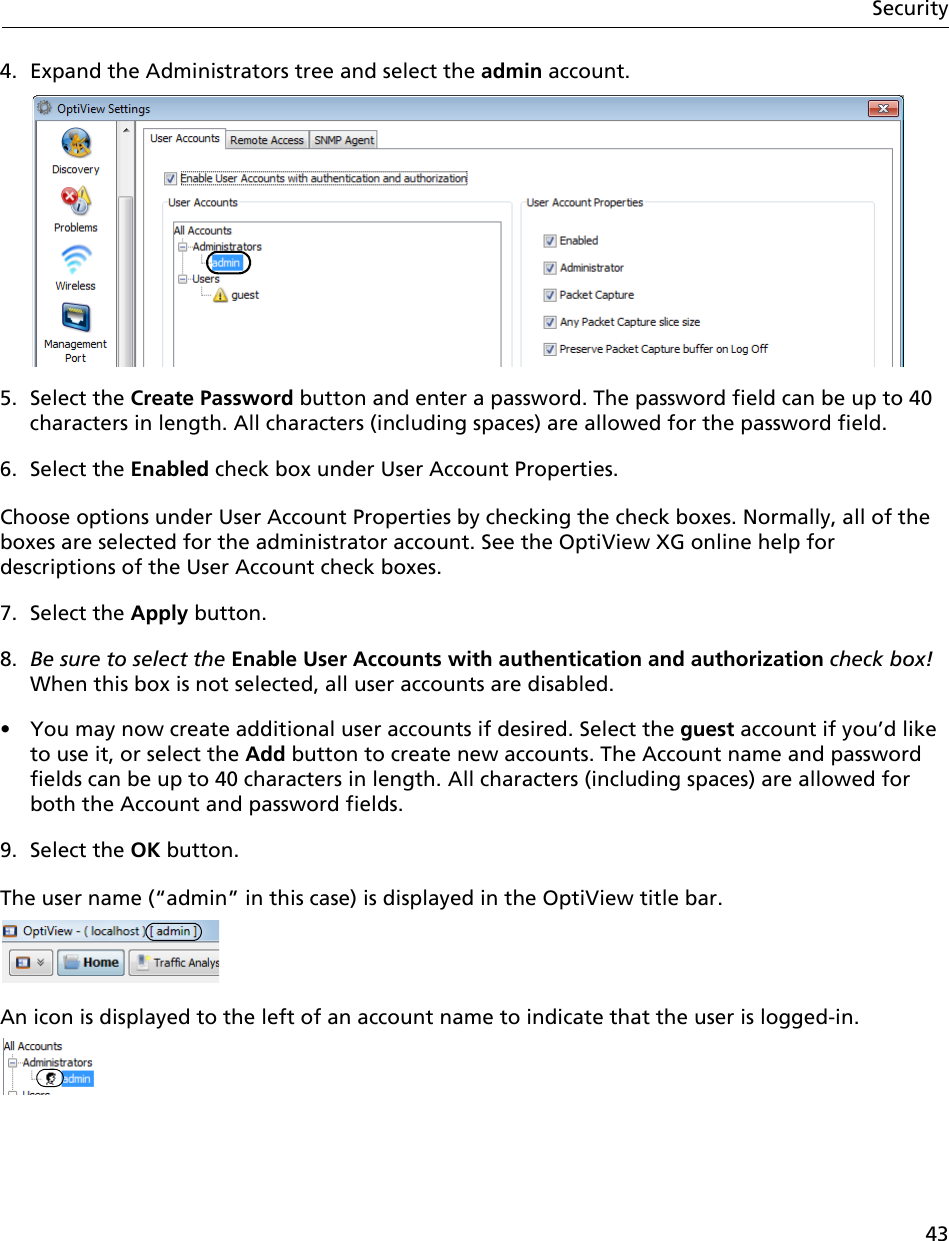
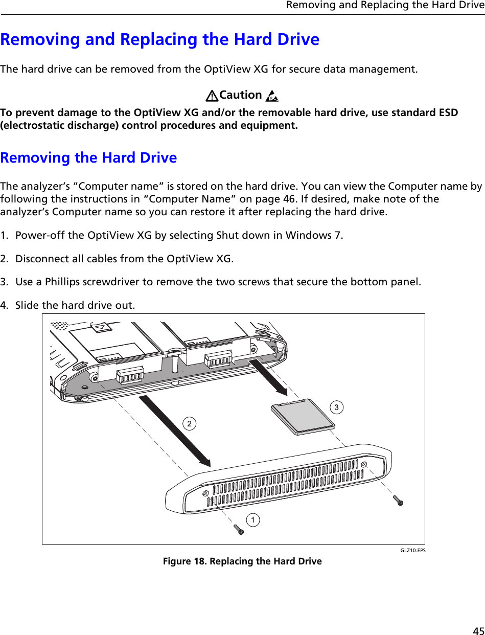
- 1. Updated User Manual
- 2. Users manual
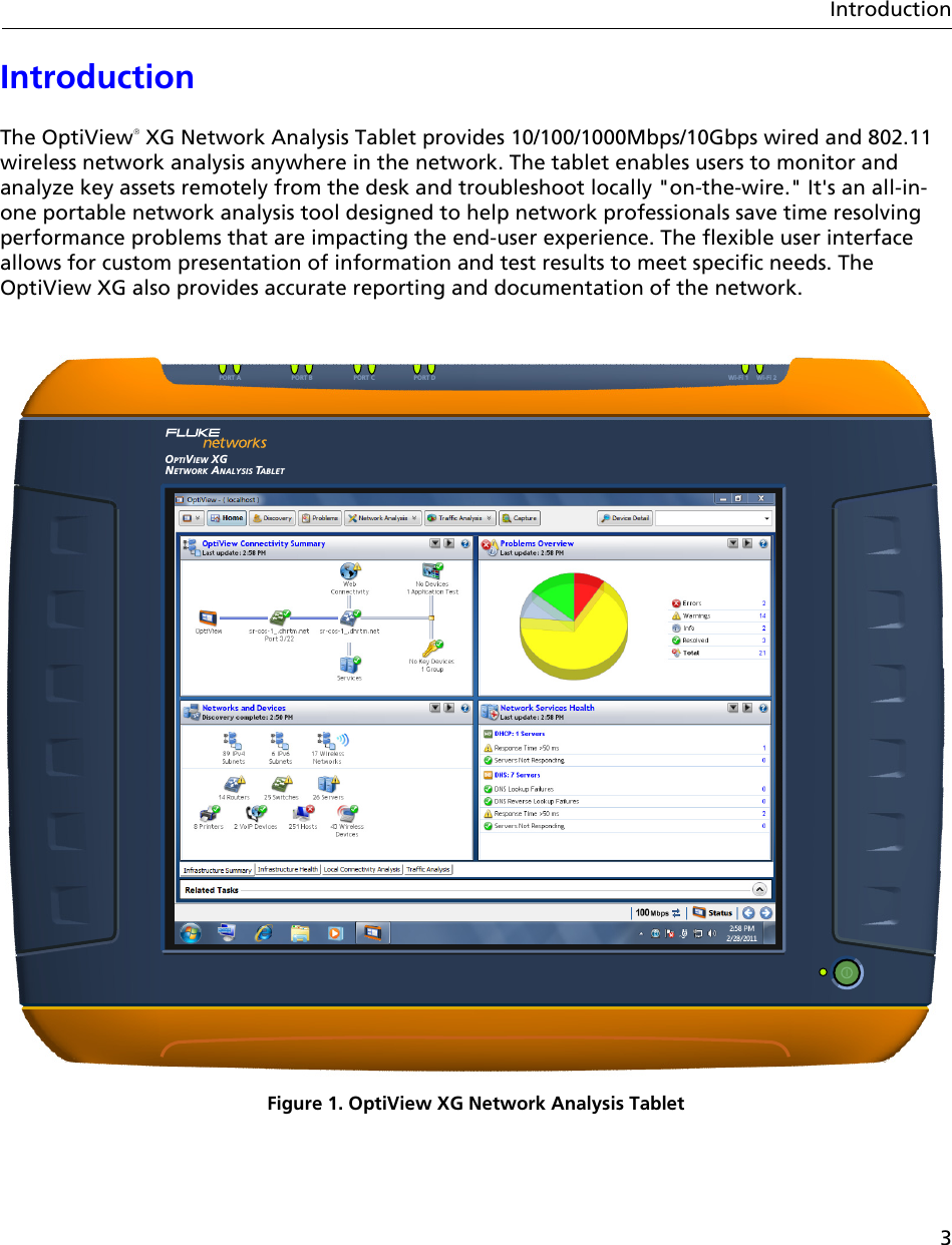
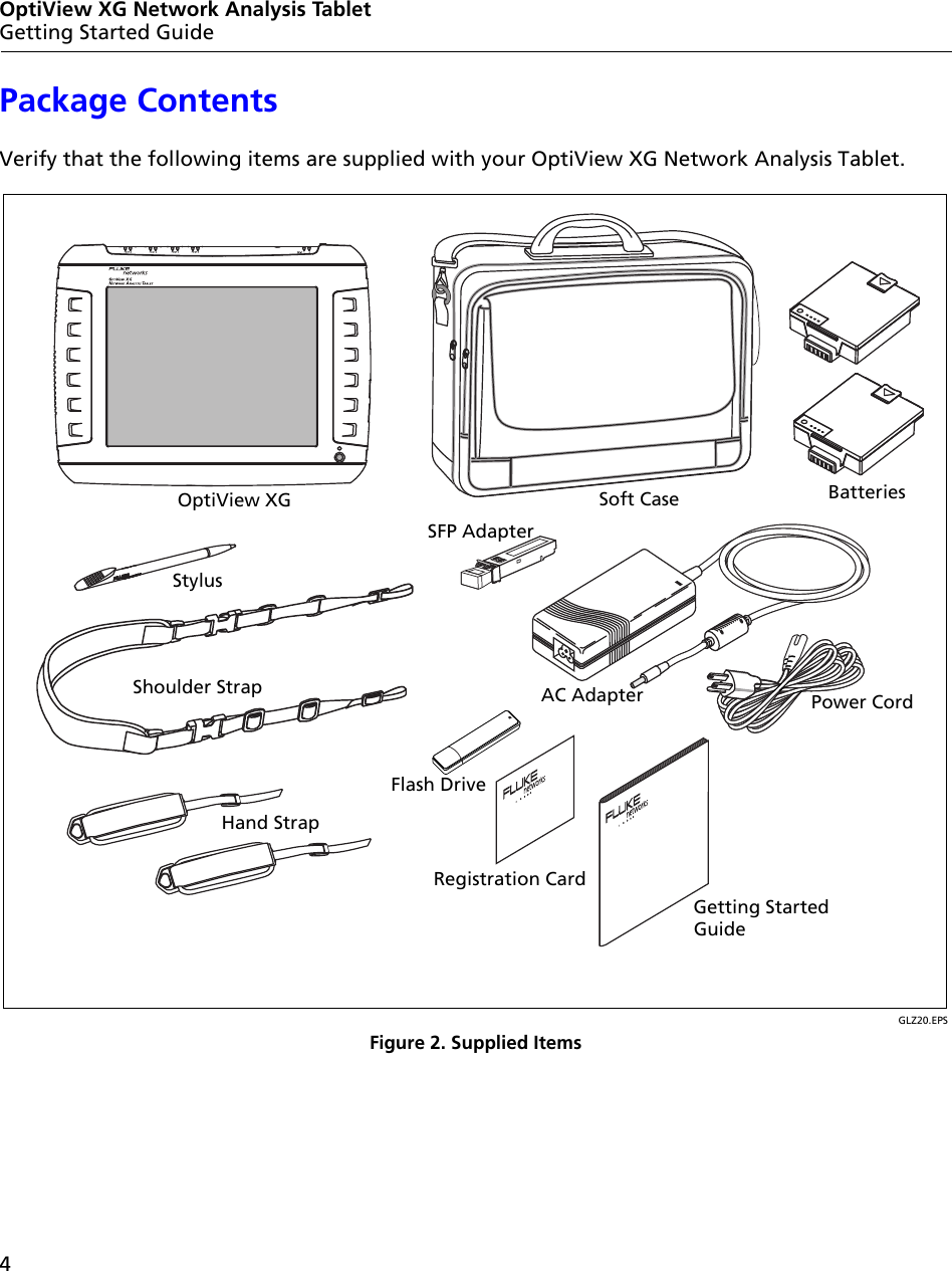
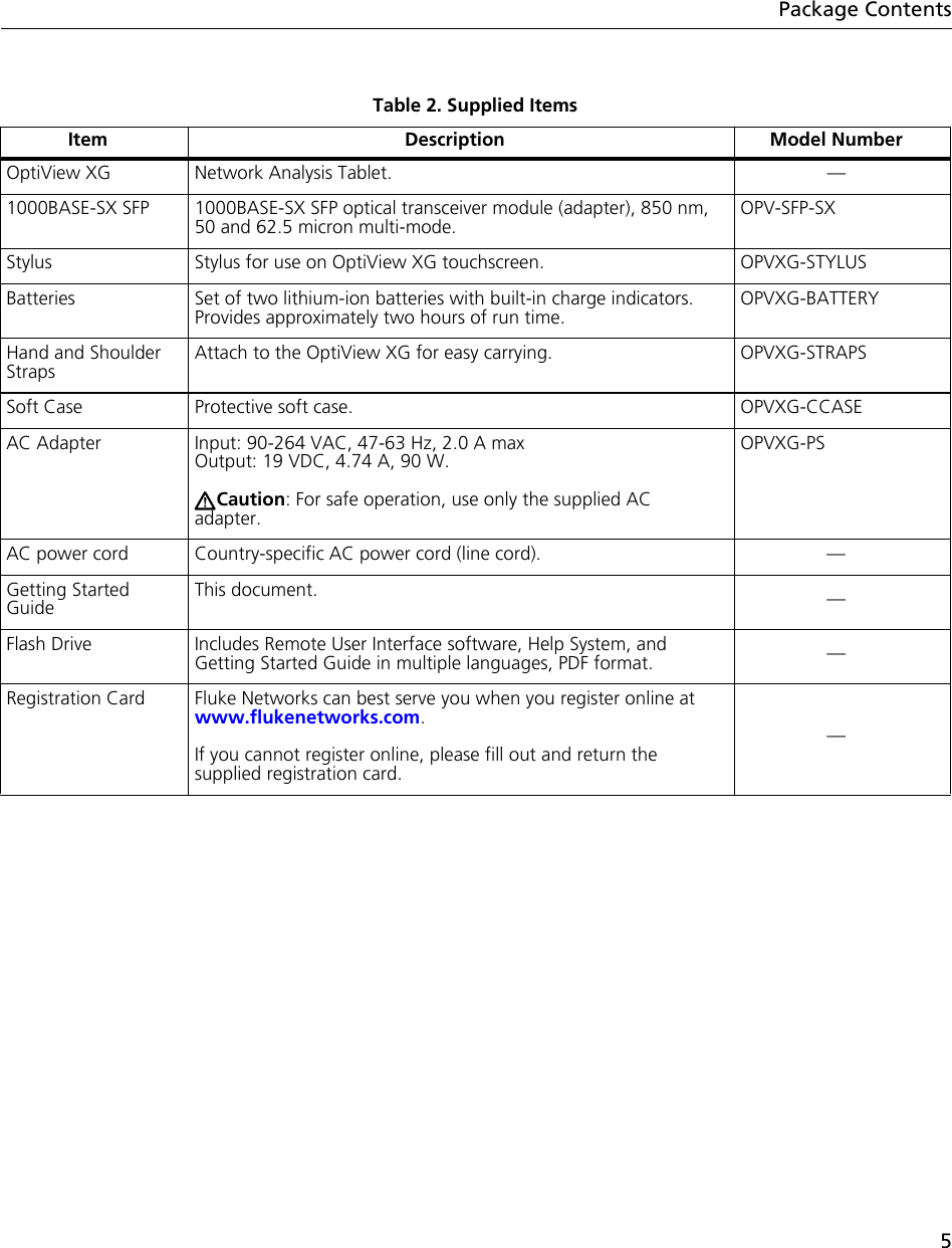
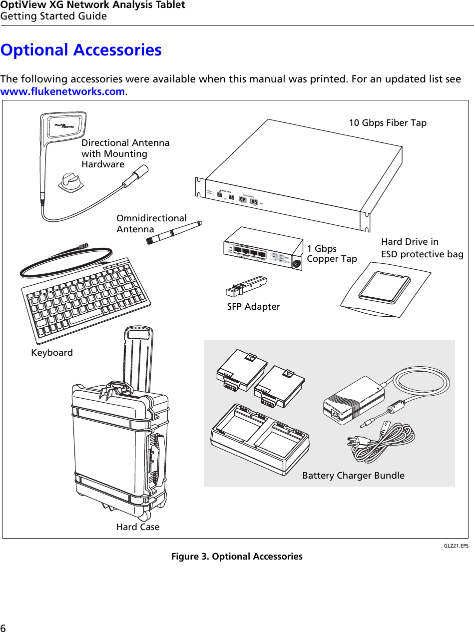
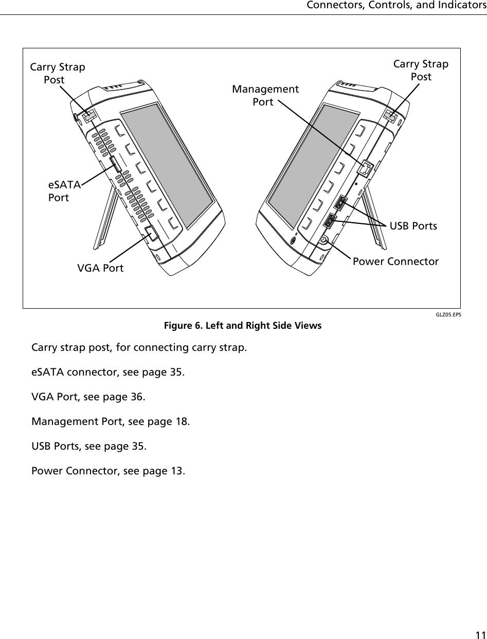
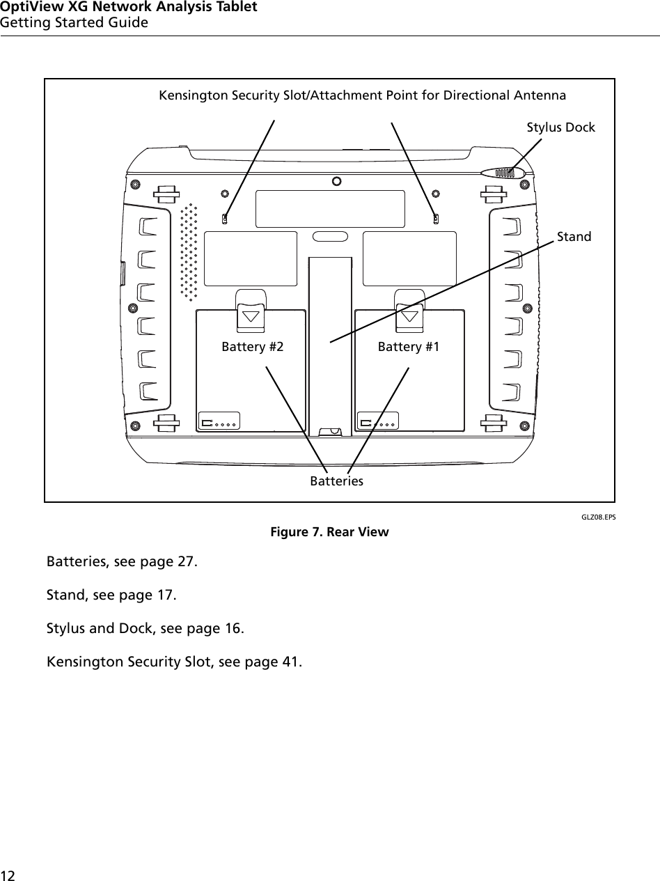
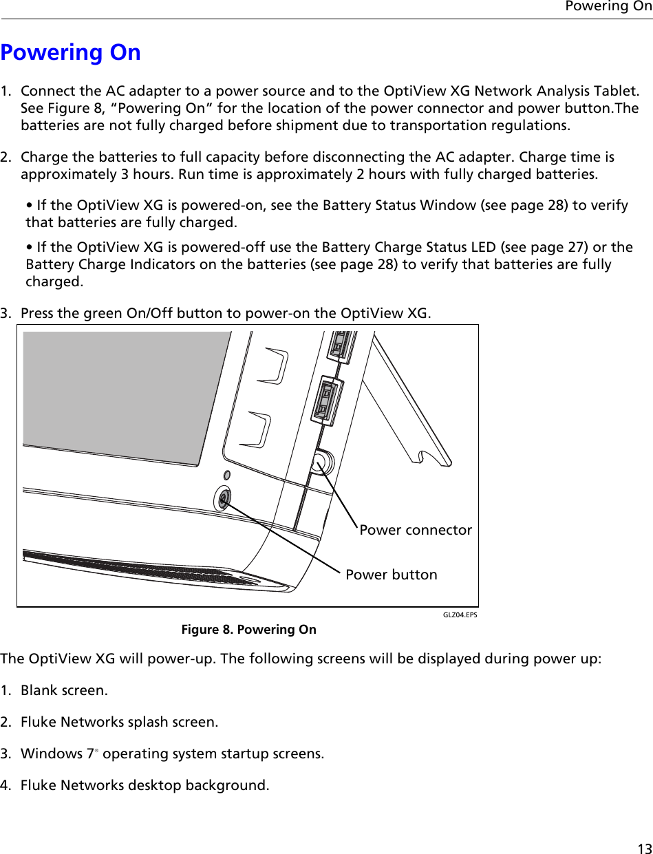
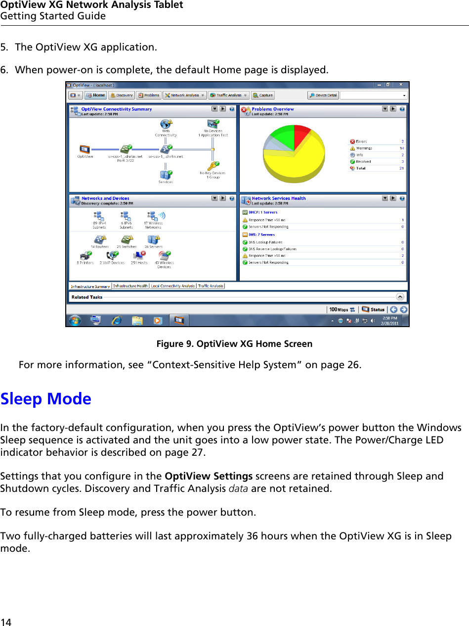
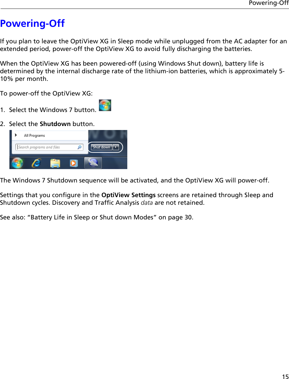
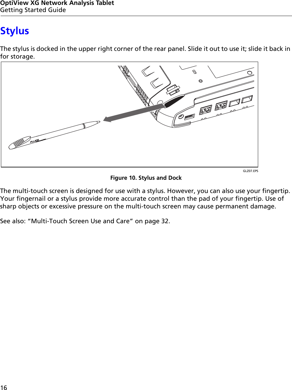
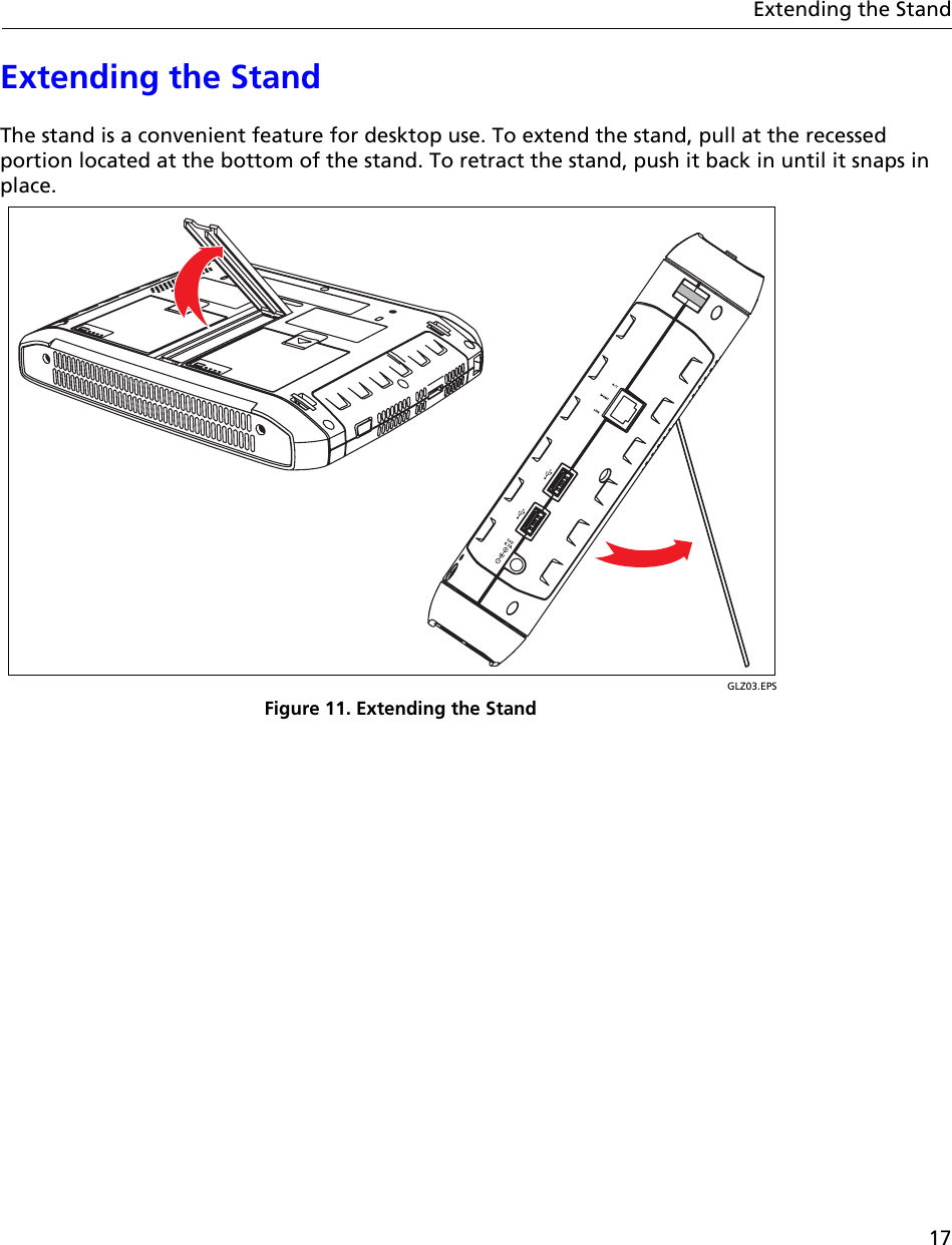
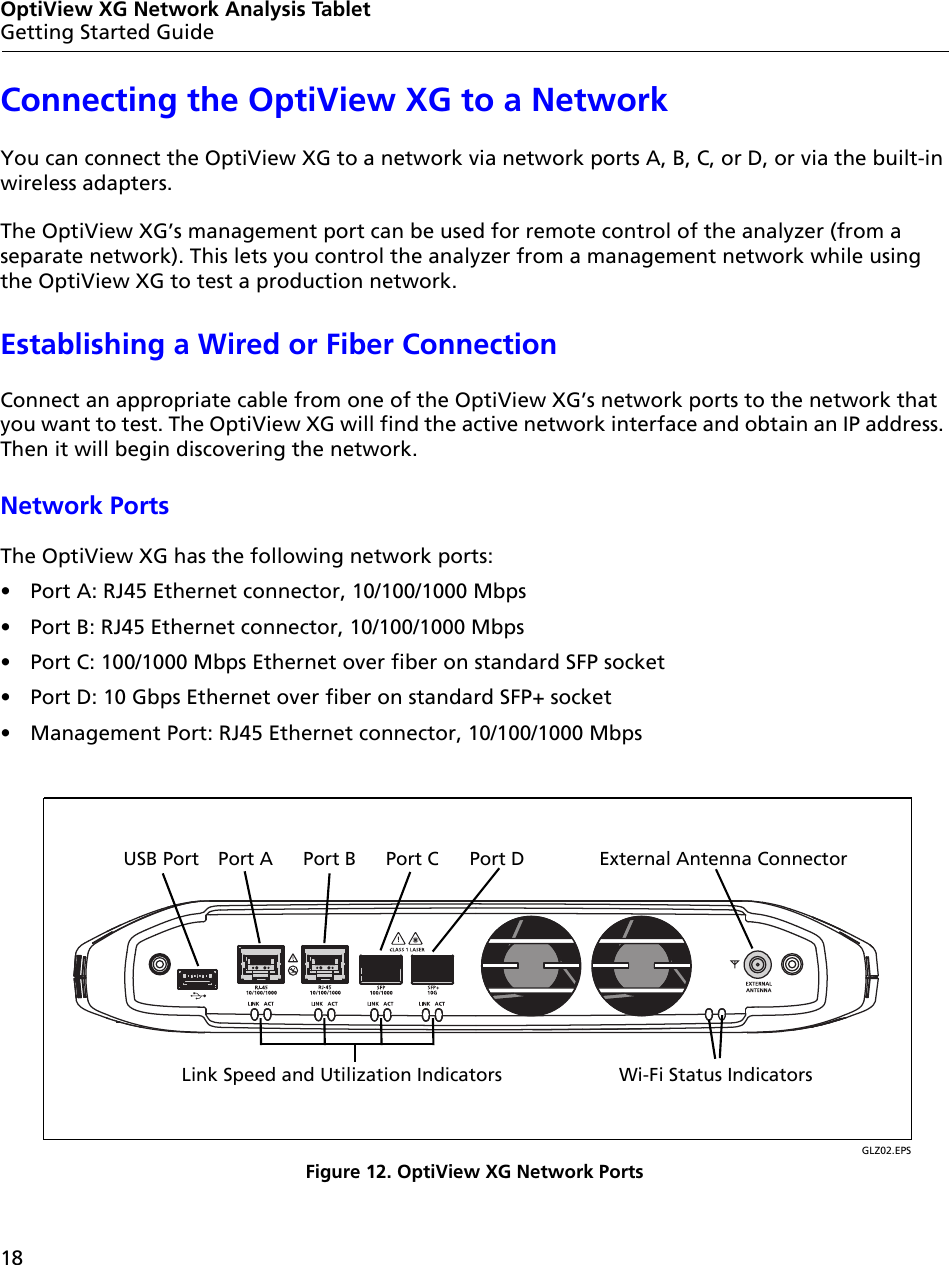
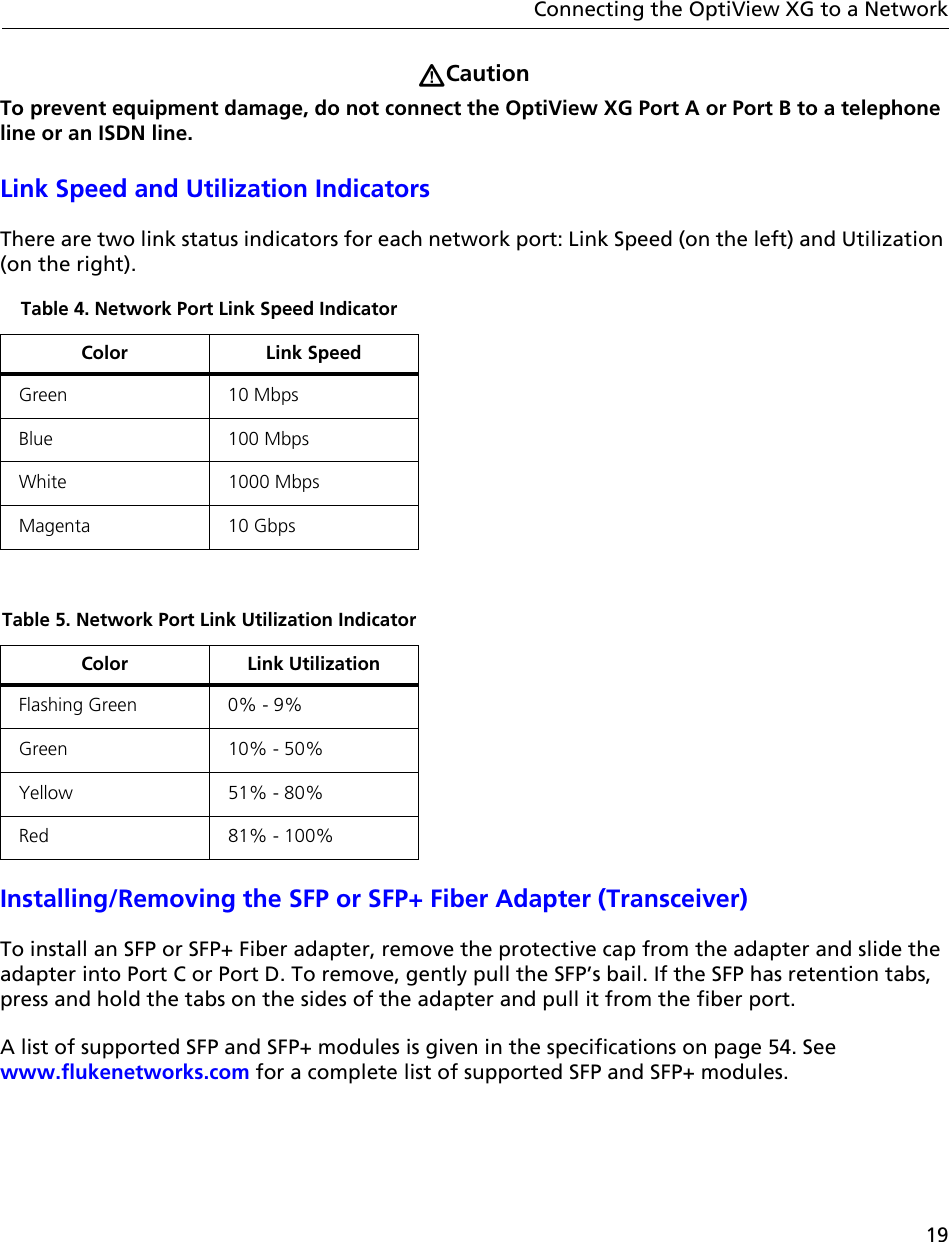
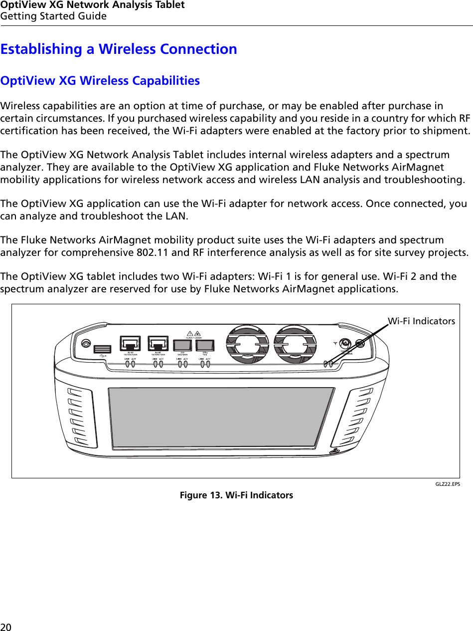
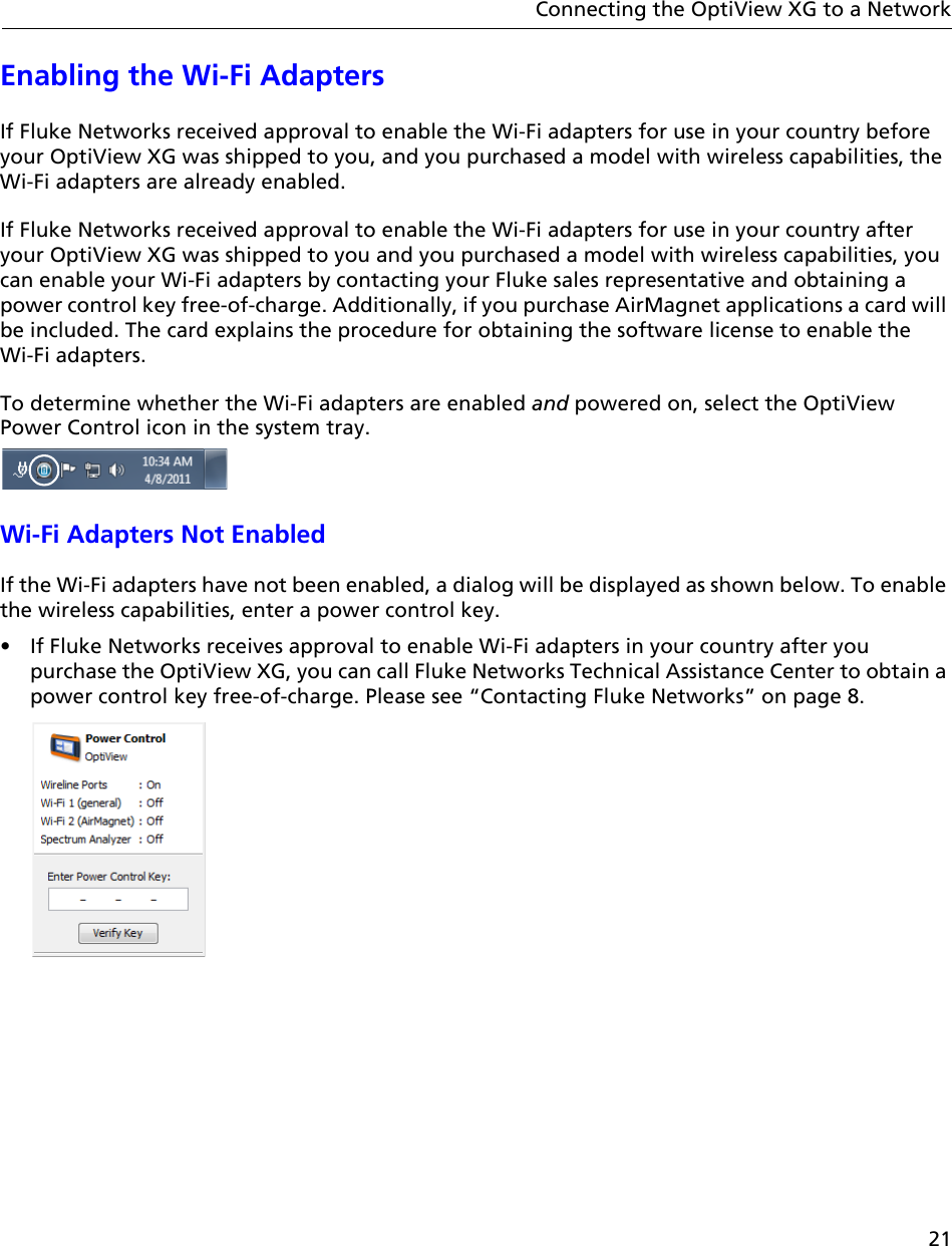
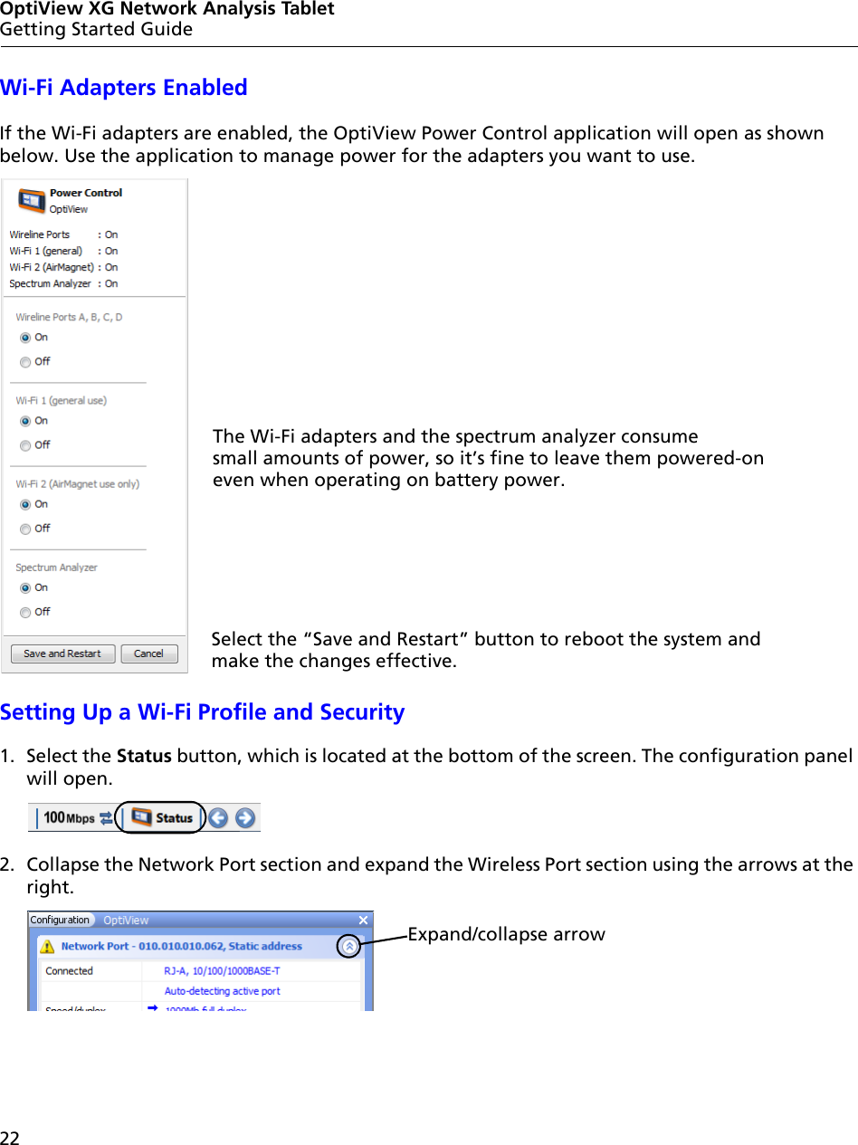
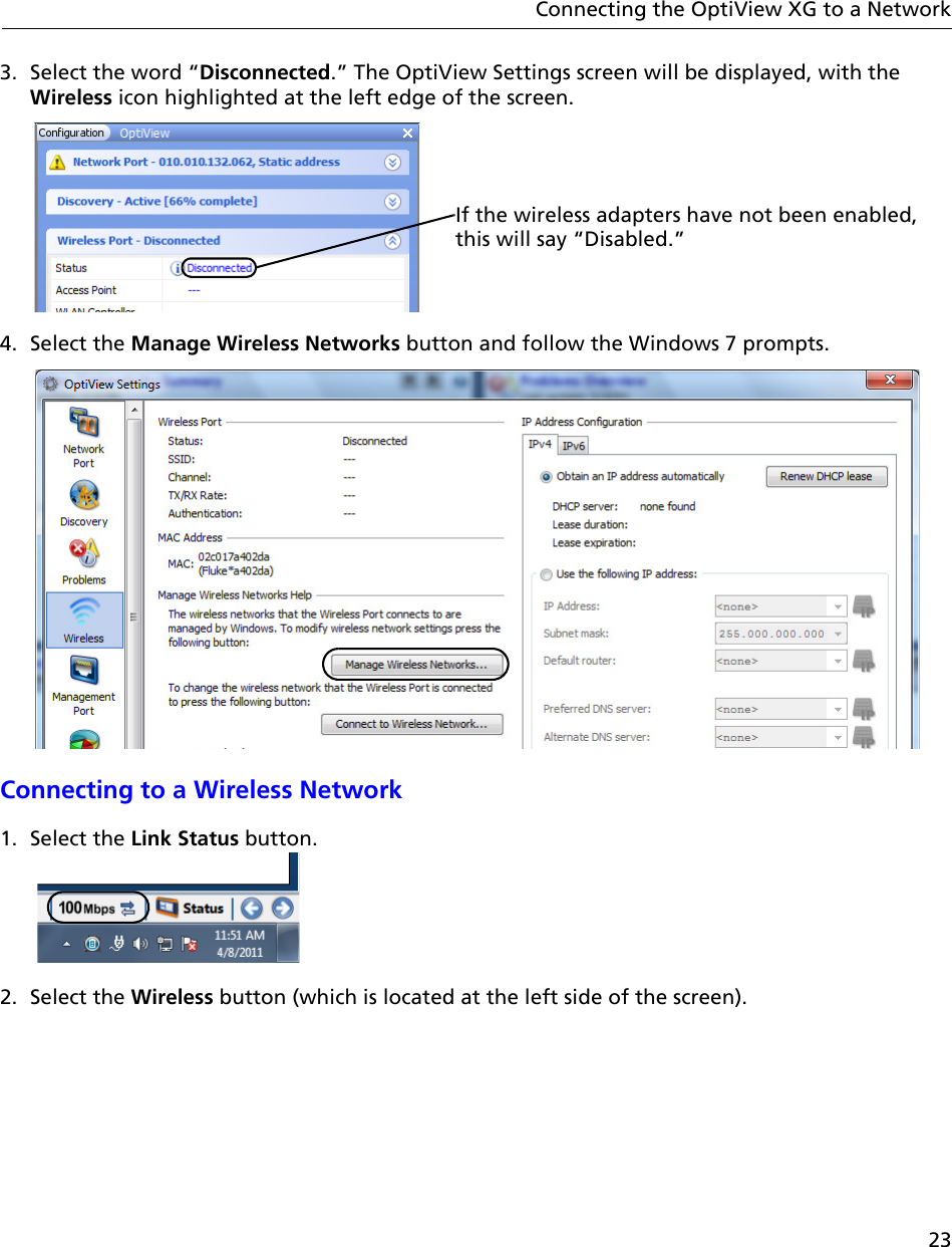
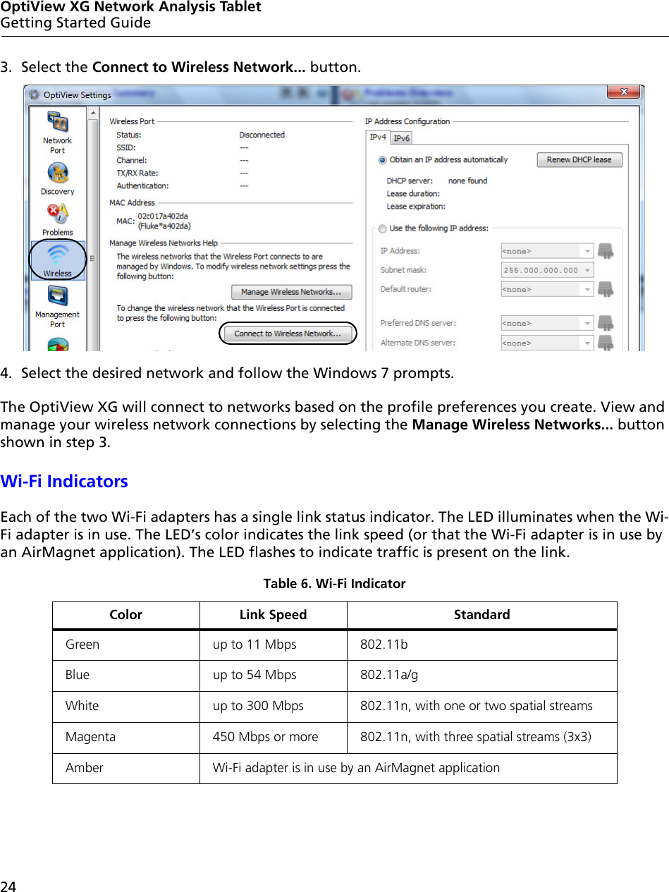
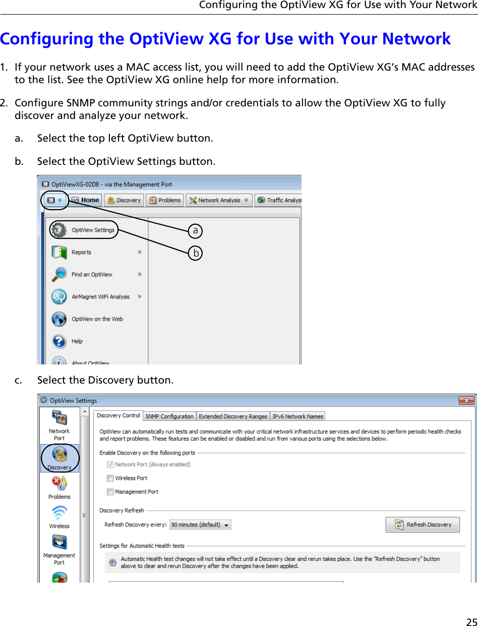
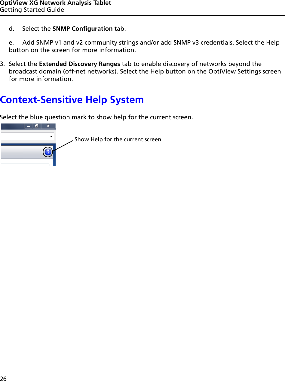
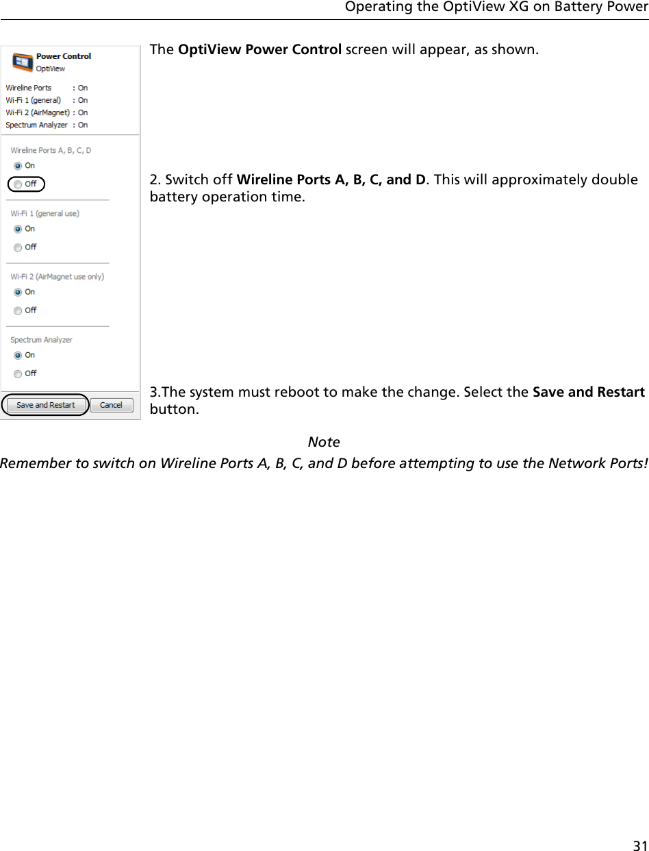
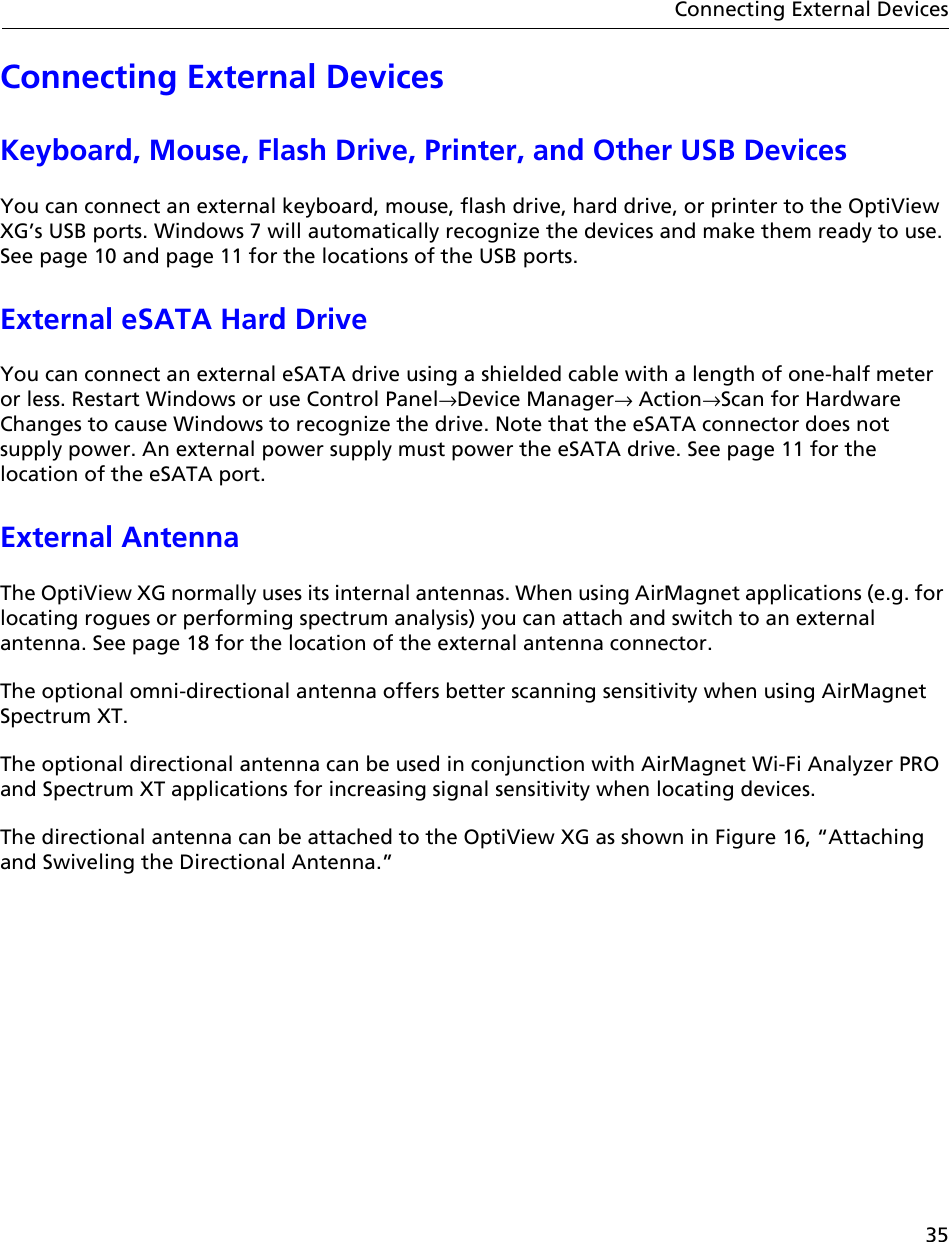
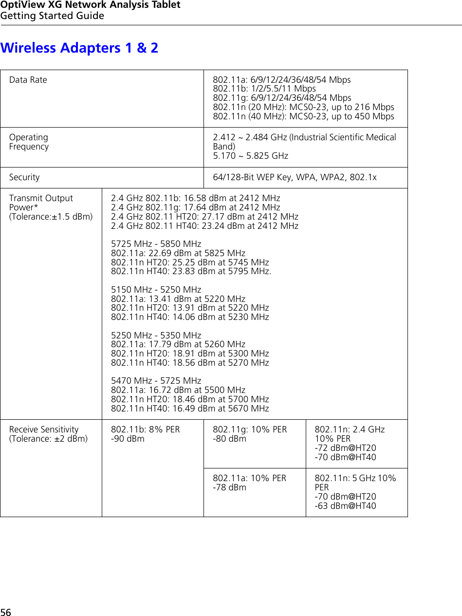
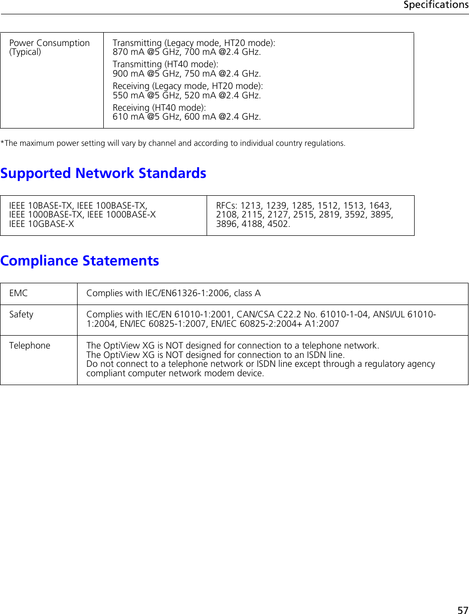
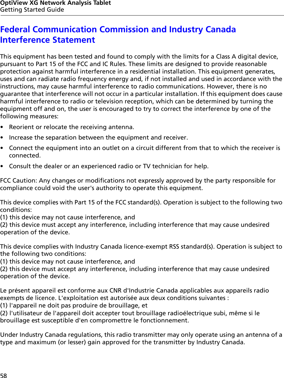
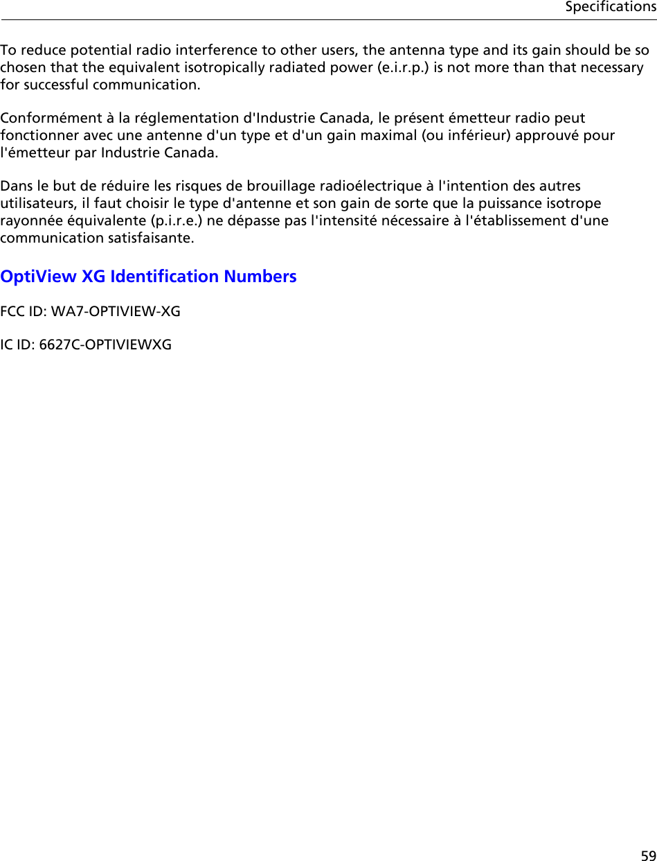
Updated User Manual