NIKON TRIMBLE NT0001 Bluetooth module User Manual TS635 manual 2
NIKON-TRIMBLE CO., LTD. Bluetooth module TS635 manual 2
UserManual.wiki
>
NIKON TRIMBLE
>
NT0001 User Manual
>
Host 3 user manual 2 of 2
Contents
1.
Host 1 user manual 1 of 4
2.
Host 1 user manual 2 of 4
3.
Host 1 user manual 3 of 4
4.
Host 1 user manual 4 of 4
5.
Host 2 user manual 1 of 3
6.
Host 2 user manual 2 of 3
7.
Host 2 user manual 3 of 3
8.
Host 3 user manual 1 of 2
9.
Host 3 user manual 2 of 2
Host 3 user manual 2 of 2
Navigation menu
Upload a User Manual
Namespaces
Wiki Guide
HTML
PDF
Info
Views
User Manual
Discussion / Help
Navigation

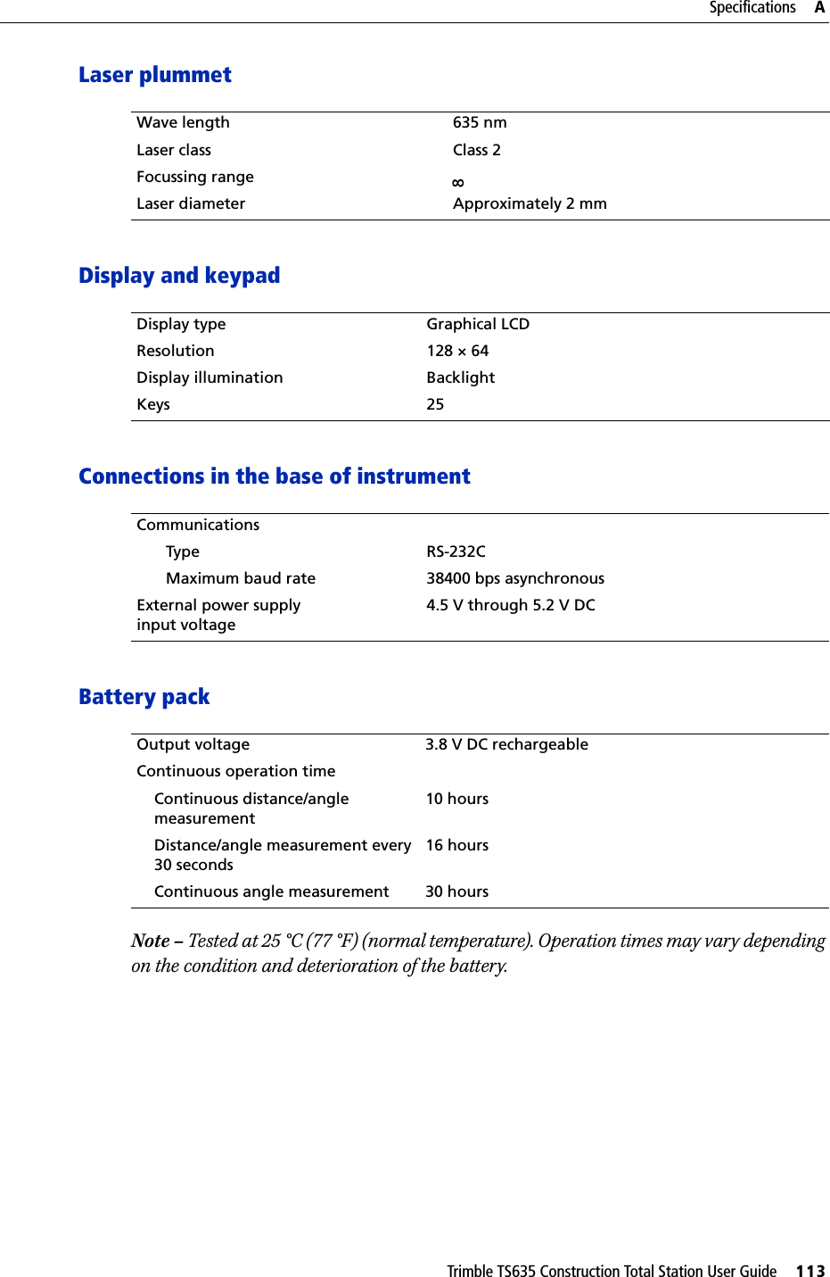
![4 Trimble TS635 Construction Total Station User GuideLCD backlight, laser pointer, beep sound, and contrast adjustment . . . . . . . . . . . . . 39[DSP] button. . . . . . . . . . . . . . . . . . . . . . . . . . . . . . . . . . . . . . . . . . . . . . . . 40[MODE] button . . . . . . . . . . . . . . . . . . . . . . . . . . . . . . . . . . . . . . . . . . . . . . 41[HOT] key . . . . . . . . . . . . . . . . . . . . . . . . . . . . . . . . . . . . . . . . . . . . . . . . . 42Bubble indicator . . . . . . . . . . . . . . . . . . . . . . . . . . . . . . . . . . . . . . . . . . . . . 42Laser plummet . . . . . . . . . . . . . . . . . . . . . . . . . . . . . . . . . . . . . . . . . . . . . . 43Turning on the instrument . . . . . . . . . . . . . . . . . . . . . . . . . . . . . . . . . . . . . . . . . . . 44Turning off the instrument . . . . . . . . . . . . . . . . . . . . . . . . . . . . . . . . . . . . . . . . . . . 44Sleep mode. . . . . . . . . . . . . . . . . . . . . . . . . . . . . . . . . . . . . . . . . . . . . . . . . 44Regional configuration. . . . . . . . . . . . . . . . . . . . . . . . . . . . . . . . . . . . . . . . . . . . . . 45List available jobs or data . . . . . . . . . . . . . . . . . . . . . . . . . . . . . . . . . . . . . . . . . . . . 46Entering data. . . . . . . . . . . . . . . . . . . . . . . . . . . . . . . . . . . . . . . . . . . . . . . . . . . . 46Entering a point name or number . . . . . . . . . . . . . . . . . . . . . . . . . . . . . . . . . . 46Entering a code . . . . . . . . . . . . . . . . . . . . . . . . . . . . . . . . . . . . . . . . . . . . . . 49Entering values in feet and inches . . . . . . . . . . . . . . . . . . . . . . . . . . . . . . . . . . 51Creating or opening a job . . . . . . . . . . . . . . . . . . . . . . . . . . . . . . . . . . . . . . . . . . . . 51Creating a new job . . . . . . . . . . . . . . . . . . . . . . . . . . . . . . . . . . . . . . . . . . . . 52Creating a control job . . . . . . . . . . . . . . . . . . . . . . . . . . . . . . . . . . . . . . . . . . 52Measuring distances . . . . . . . . . . . . . . . . . . . . . . . . . . . . . . . . . . . . . . . . . . . . . . . 53Sighting a prism reflector. . . . . . . . . . . . . . . . . . . . . . . . . . . . . . . . . . . . . . . . 53Taking a distance measurement . . . . . . . . . . . . . . . . . . . . . . . . . . . . . . . . . . . 53Viewing and changing the measurement settings . . . . . . . . . . . . . . . . . . . . . . . . 544 Applications . . . . . . . . . . . . . . . . . . . . . . . . . . . . . . . . . . . 55HA reset and angle operations. . . . . . . . . . . . . . . . . . . . . . . . . . . . . . . . . . . . . . . . . 56Setting the horizontal angle to 0 . . . . . . . . . . . . . . . . . . . . . . . . . . . . . . . . . . . 56Entering the horizontal angle . . . . . . . . . . . . . . . . . . . . . . . . . . . . . . . . . . . . . 56Station setup . . . . . . . . . . . . . . . . . . . . . . . . . . . . . . . . . . . . . . . . . . . . . . . . . . . . 56Baseline . . . . . . . . . . . . . . . . . . . . . . . . . . . . . . . . . . . . . . . . . . . . . . . . . . . 57Known. . . . . . . . . . . . . . . . . . . . . . . . . . . . . . . . . . . . . . . . . . . . . . . . . . . . 58Base XYZ . . . . . . . . . . . . . . . . . . . . . . . . . . . . . . . . . . . . . . . . . . . . . . . . . . 60Remote BM . . . . . . . . . . . . . . . . . . . . . . . . . . . . . . . . . . . . . . . . . . . . . . . . 60BS Check . . . . . . . . . . . . . . . . . . . . . . . . . . . . . . . . . . . . . . . . . . . . . . . . . . 61Layout menu . . . . . . . . . . . . . . . . . . . . . . . . . . . . . . . . . . . . . . . . . . . . . . . . . . . . 62L-O to Point . . . . . . . . . . . . . . . . . . . . . . . . . . . . . . . . . . . . . . . . . . . . . . . . 62L-O from Line . . . . . . . . . . . . . . . . . . . . . . . . . . . . . . . . . . . . . . . . . . . . . . . 63L-O from Arc. . . . . . . . . . . . . . . . . . . . . . . . . . . . . . . . . . . . . . . . . . . . . . . . 64XYZ . . . . . . . . . . . . . . . . . . . . . . . . . . . . . . . . . . . . . . . . . . . . . . . . . . . . . 65Programs menu . . . . . . . . . . . . . . . . . . . . . . . . . . . . . . . . . . . . . . . . . . . . . . . . . . 67Remote distance measurement (RDM) - overview . . . . . . . . . . . . . . . . . . . . . . . . 68RDM (Radial) . . . . . . . . . . . . . . . . . . . . . . . . . . . . . . . . . . . . . . . . . . . . . . . 69RDM (Cont) . . . . . . . . . . . . . . . . . . . . . . . . . . . . . . . . . . . . . . . . . . . . . . . . 69REM . . . . . . . . . . . . . . . . . . . . . . . . . . . . . . . . . . . . . . . . . . . . . . . . . . . . . 70V-Plane . . . . . . . . . . . . . . . . . . . . . . . . . . . . . . . . . . . . . . . . . . . . . . . . . . . 70Cogo . . . . . . . . . . . . . . . . . . . . . . . . . . . . . . . . . . . . . . . . . . . . . . . . . . . . . 71Recording measurement data . . . . . . . . . . . . . . . . . . . . . . . . . . . . . . . . . . . . . . . . . 83](https://usermanual.wiki/NIKON-TRIMBLE/NT0001.Host-3-user-manual-2-of-2/User-Guide-1089797-Page-6.png)
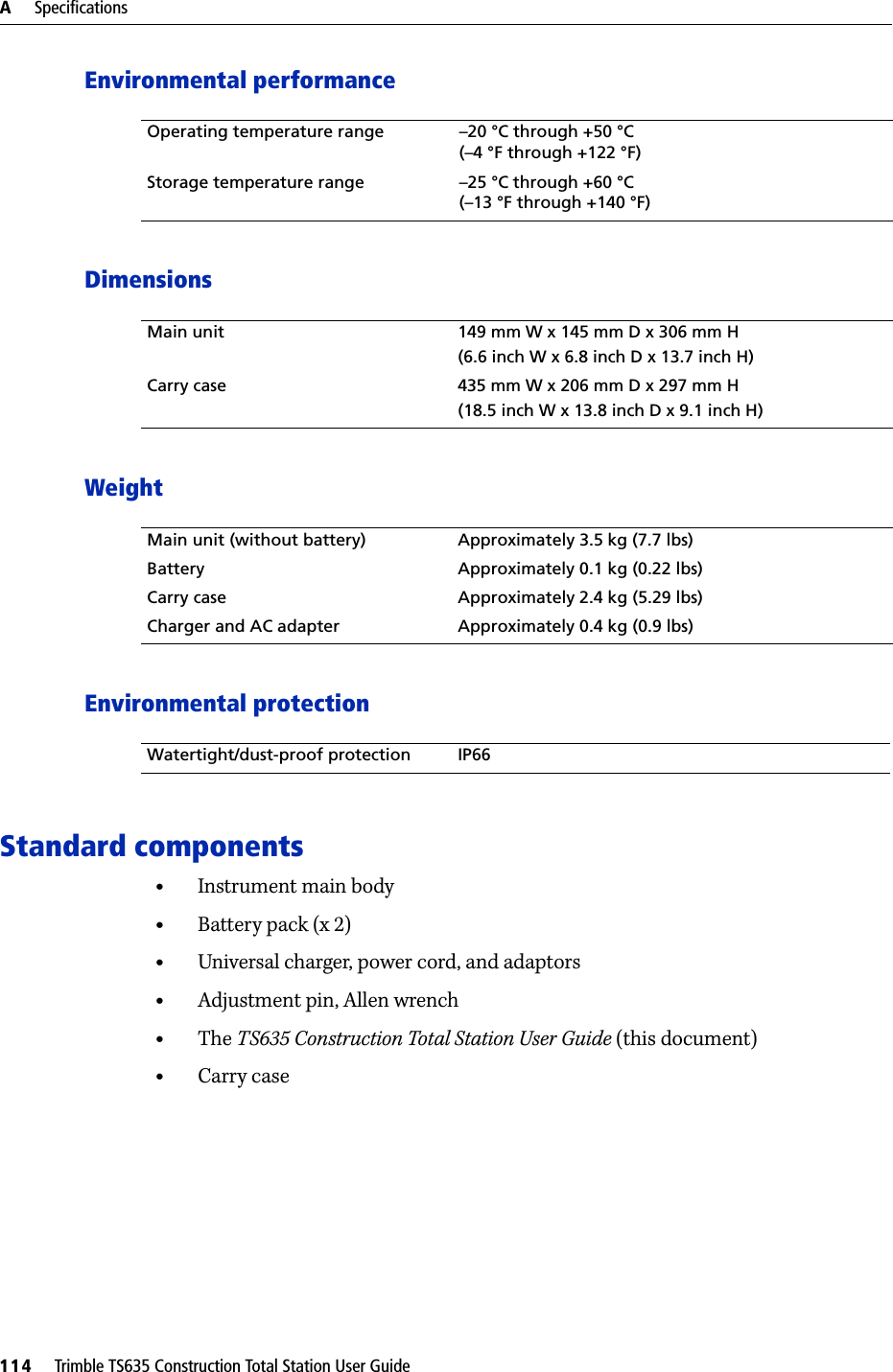
![Trimble TS635 Construction Total Station User Guide 5Switching between display screens . . . . . . . . . . . . . . . . . . . . . . . . . . . . . . . . . . . . . . 835 Menu Screen . . . . . . . . . . . . . . . . . . . . . . . . . . . . . . . . . . . 85Job . . . . . . . . . . . . . . . . . . . . . . . . . . . . . . . . . . . . . . . . . . . . . . . . . . . . . . . . . . 86Opening an existing job . . . . . . . . . . . . . . . . . . . . . . . . . . . . . . . . . . . . . . . . . 86Creating a new job . . . . . . . . . . . . . . . . . . . . . . . . . . . . . . . . . . . . . . . . . . . . 86Deleting a job . . . . . . . . . . . . . . . . . . . . . . . . . . . . . . . . . . . . . . . . . . . . . . . 88Setting the control job. . . . . . . . . . . . . . . . . . . . . . . . . . . . . . . . . . . . . . . . . . 89Displaying job information. . . . . . . . . . . . . . . . . . . . . . . . . . . . . . . . . . . . . . . 89Settings (basic job settings). . . . . . . . . . . . . . . . . . . . . . . . . . . . . . . . . . . . . . . . . . . 90Angle . . . . . . . . . . . . . . . . . . . . . . . . . . . . . . . . . . . . . . . . . . . . . . . . . . . . 90Distance . . . . . . . . . . . . . . . . . . . . . . . . . . . . . . . . . . . . . . . . . . . . . . . . . . 90Coordinate . . . . . . . . . . . . . . . . . . . . . . . . . . . . . . . . . . . . . . . . . . . . . . . . . 93Communications . . . . . . . . . . . . . . . . . . . . . . . . . . . . . . . . . . . . . . . . . . . . . 93Unit . . . . . . . . . . . . . . . . . . . . . . . . . . . . . . . . . . . . . . . . . . . . . . . . . . . . . 93Power saving. . . . . . . . . . . . . . . . . . . . . . . . . . . . . . . . . . . . . . . . . . . . . . . . 94Recording. . . . . . . . . . . . . . . . . . . . . . . . . . . . . . . . . . . . . . . . . . . . . . . . . . 94Other settings . . . . . . . . . . . . . . . . . . . . . . . . . . . . . . . . . . . . . . . . . . . . . . . 94Data . . . . . . . . . . . . . . . . . . . . . . . . . . . . . . . . . . . . . . . . . . . . . . . . . . . . . . . . . 95Viewing coordinate data . . . . . . . . . . . . . . . . . . . . . . . . . . . . . . . . . . . . . . . . 95UP, MP, CC, SS, and SO records . . . . . . . . . . . . . . . . . . . . . . . . . . . . . . . . . . . . 96Deleting coordinate records . . . . . . . . . . . . . . . . . . . . . . . . . . . . . . . . . . . . . . 96Editing coordinate records . . . . . . . . . . . . . . . . . . . . . . . . . . . . . . . . . . . . . . . 96Searching coordinate records . . . . . . . . . . . . . . . . . . . . . . . . . . . . . . . . . . . . . 97Entering coordinates . . . . . . . . . . . . . . . . . . . . . . . . . . . . . . . . . . . . . . . . . . 98Communication . . . . . . . . . . . . . . . . . . . . . . . . . . . . . . . . . . . . . . . . . . . . . . . . . . 99Downloading coordinate data. . . . . . . . . . . . . . . . . . . . . . . . . . . . . . . . . . . . . 99Uploading coordinate data . . . . . . . . . . . . . . . . . . . . . . . . . . . . . . . . . . . . . . . 991sec-Key. . . . . . . . . . . . . . . . . . . . . . . . . . . . . . . . . . . . . . . . . . . . . . . . . . . . . . .101[MSR] button settings . . . . . . . . . . . . . . . . . . . . . . . . . . . . . . . . . . . . . . . . . .101[DSP] button settings . . . . . . . . . . . . . . . . . . . . . . . . . . . . . . . . . . . . . . . . . .101Calibration . . . . . . . . . . . . . . . . . . . . . . . . . . . . . . . . . . . . . . . . . . . . . . . . . . . . .102Time . . . . . . . . . . . . . . . . . . . . . . . . . . . . . . . . . . . . . . . . . . . . . . . . . . . . . . . . .1026 Checking and Adjusting . . . . . . . . . . . . . . . . . . . . . . . . . . . . 103Adjusting the electronic level . . . . . . . . . . . . . . . . . . . . . . . . . . . . . . . . . . . . . . . . .104Checking and adjusting the circular level . . . . . . . . . . . . . . . . . . . . . . . . . . . . . . . . . .104Checking and adjusting the optical/laser plummet. . . . . . . . . . . . . . . . . . . . . . . . . . . .104Zero point errors of vertical scale and horizontal angle corrections . . . . . . . . . . . . . . . . .105Checking the calibration . . . . . . . . . . . . . . . . . . . . . . . . . . . . . . . . . . . . . . . .105Adjusting the calibration . . . . . . . . . . . . . . . . . . . . . . . . . . . . . . . . . . . . . . . .106The instrument constant . . . . . . . . . . . . . . . . . . . . . . . . . . . . . . . . . . . . . . . . . . . .107Checking and adjusting the laser pointer . . . . . . . . . . . . . . . . . . . . . . . . . . . . . . . . . .108A Specifications. . . . . . . . . . . . . . . . . . . . . . . . . . . . . . . . . . 109Main body. . . . . . . . . . . . . . . . . . . . . . . . . . . . . . . . . . . . . . . . . . . . . . . . . . . . . .110](https://usermanual.wiki/NIKON-TRIMBLE/NT0001.Host-3-user-manual-2-of-2/User-Guide-1089797-Page-7.png)
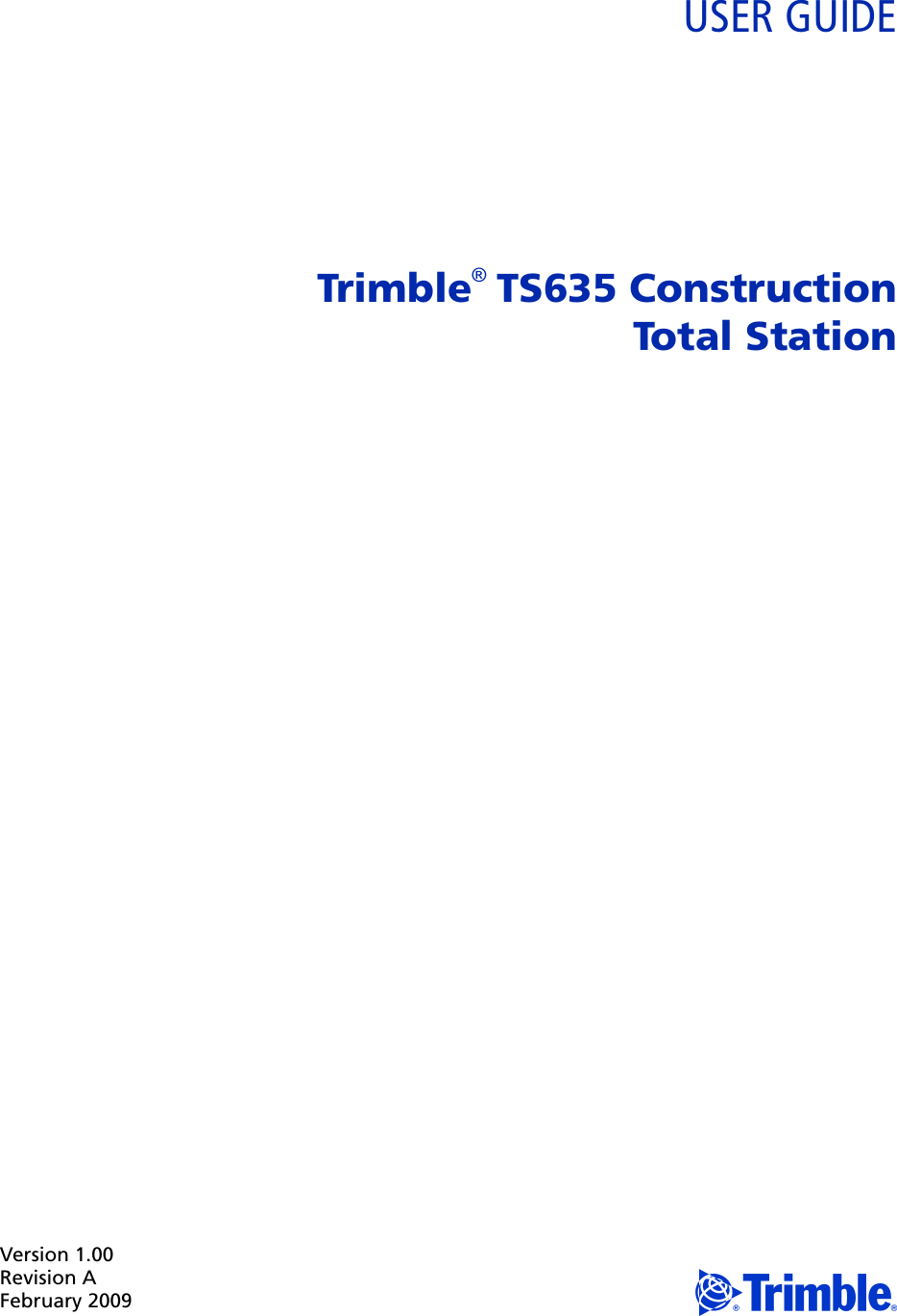
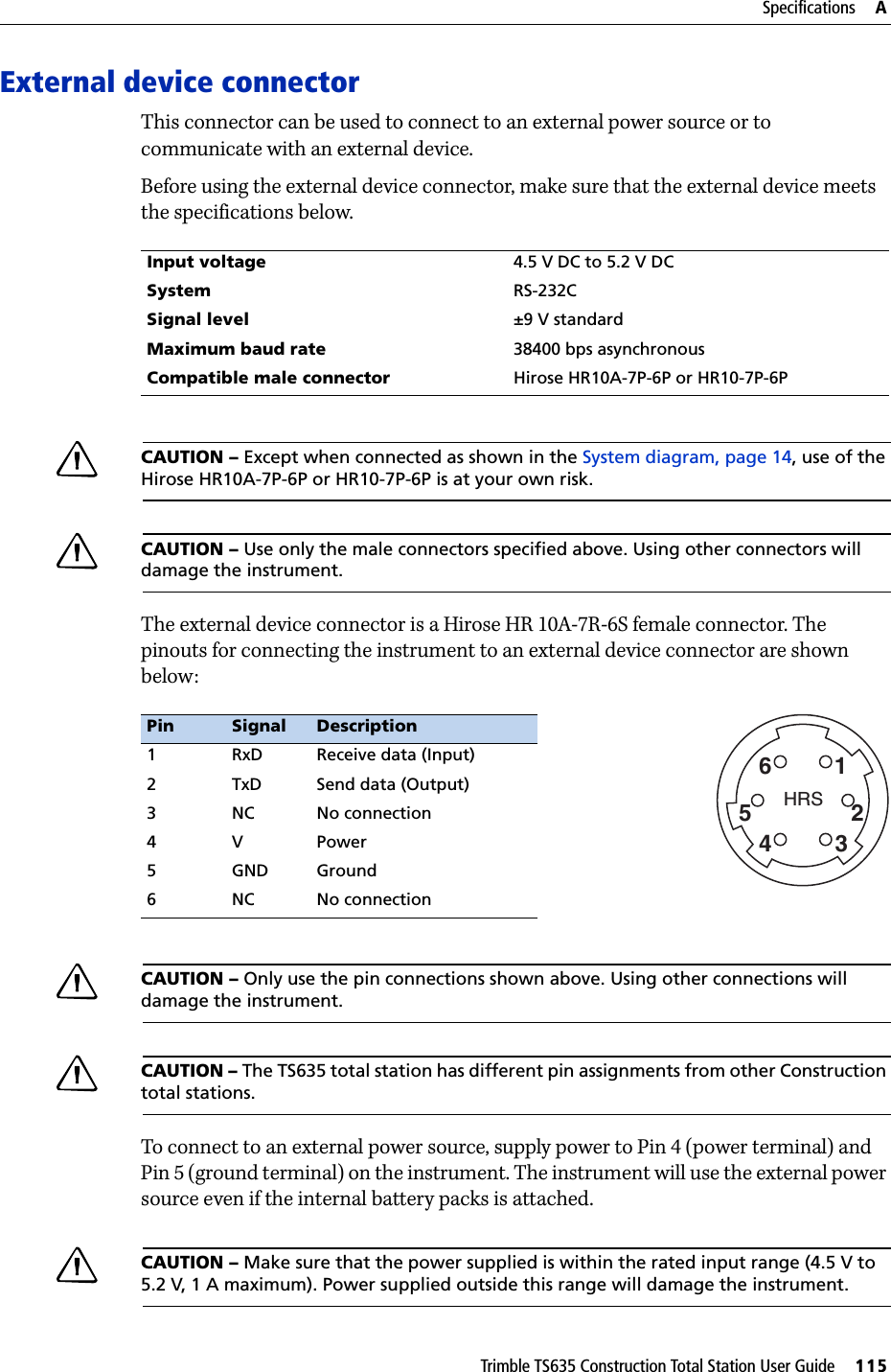
![CHAPTER4Trimble TS635 Construction Total Station User Guide 55Applications 4In this chapter:QHA reset and angle operationsQStation setupQLayout menuQPrograms menuQRecording measurement dataQSwitching between display screensThis chapter describes the menu and display screens, and TS635 Construction Total Station applications.Use the following keystrokes when working in the display screens and when you use the applications: To switch between display screensPress [DSP]. See also page 83.To change HT Press [HOT]To record points Press [ENT]](https://usermanual.wiki/NIKON-TRIMBLE/NT0001.Host-3-user-manual-2-of-2/User-Guide-1089797-Page-9.png)
![4 Applications56 Trimble TS635 Construction Total Station User GuideHA reset and angle operationsTo access the Angle menu, press [ANG] in the Basic Measurement Screen (BMS). To select a command from the Angle menu, press the corresponding number key. Alternatively, press [^] or [v] to highlight the command and then press [ENT].Setting the horizontal angle to 0Press [1] or select 0-Set in the Angle menu. The display returns to the BMS.Entering the horizontal angle1. Press [2] or select Input in the Angle menu. The HA Input screen appears. 2. Use the numeric keys to enter the horizontal angle. 3. Press [ENT].To enter 123°45'50", key in [1] [2] [3] [.] [4] [5] [5] [0].The displayed value is rounded to the minimum angle increment.Station setupTo access the Stn Setup menu, press [STN] in the BMS.To select a command from the Stn Setup menu, press the corresponding number key. Alternatively, press [^] or [v] to highlight the command and then press [ENT]. The last function used is highlighted.The station setup options are:•Baseline, page 57•Known, page 58•Base XYZ, page 60•Remote BM, page 60•BS Check, page 61](https://usermanual.wiki/NIKON-TRIMBLE/NT0001.Host-3-user-manual-2-of-2/User-Guide-1089797-Page-10.png)
![Trimble TS635 Construction Total Station User Guide 57Applications 4BaselineSelect this option for a two-point resection along a known line.1. Press [1] or select BaseLine from the Stn Setup menu.2. Enter a known point as P1.If you enter a new point name, a coordinate input screen appears.Sight P1 and press [MSR1] or [MSR2] to take a measurement. Press [ENT].3. Choose how you want to define a known line:–To define the line by entering P2 coordinates, press [1] or select By Coord. –To define the line by entering the azimuth, press [2] or select By Angle.a. If you select By Angle, the azimuth input screen appears: Enter the angle value and press [ENT].A measurement screen appears.b. Sight P2 and press [MSR1] or [MSR2] to take a measurement. Press [ENT]. After the measurement to P2 is completed, press [ENT]. The coordinates of the station are calculated.4. To record the station, press [ENT] or the REC softkey.5. To check the measurement, press the DSP softkey. If you defined the line by entering its azimuth, the HD and VD between P1 and P2 are displayed.If you defined the line by entering the P2 coordinates, the difference of HD (dHD) and VD (dZ) between your measurement data and input coordinate data are displayed.](https://usermanual.wiki/NIKON-TRIMBLE/NT0001.Host-3-user-manual-2-of-2/User-Guide-1089797-Page-11.png)
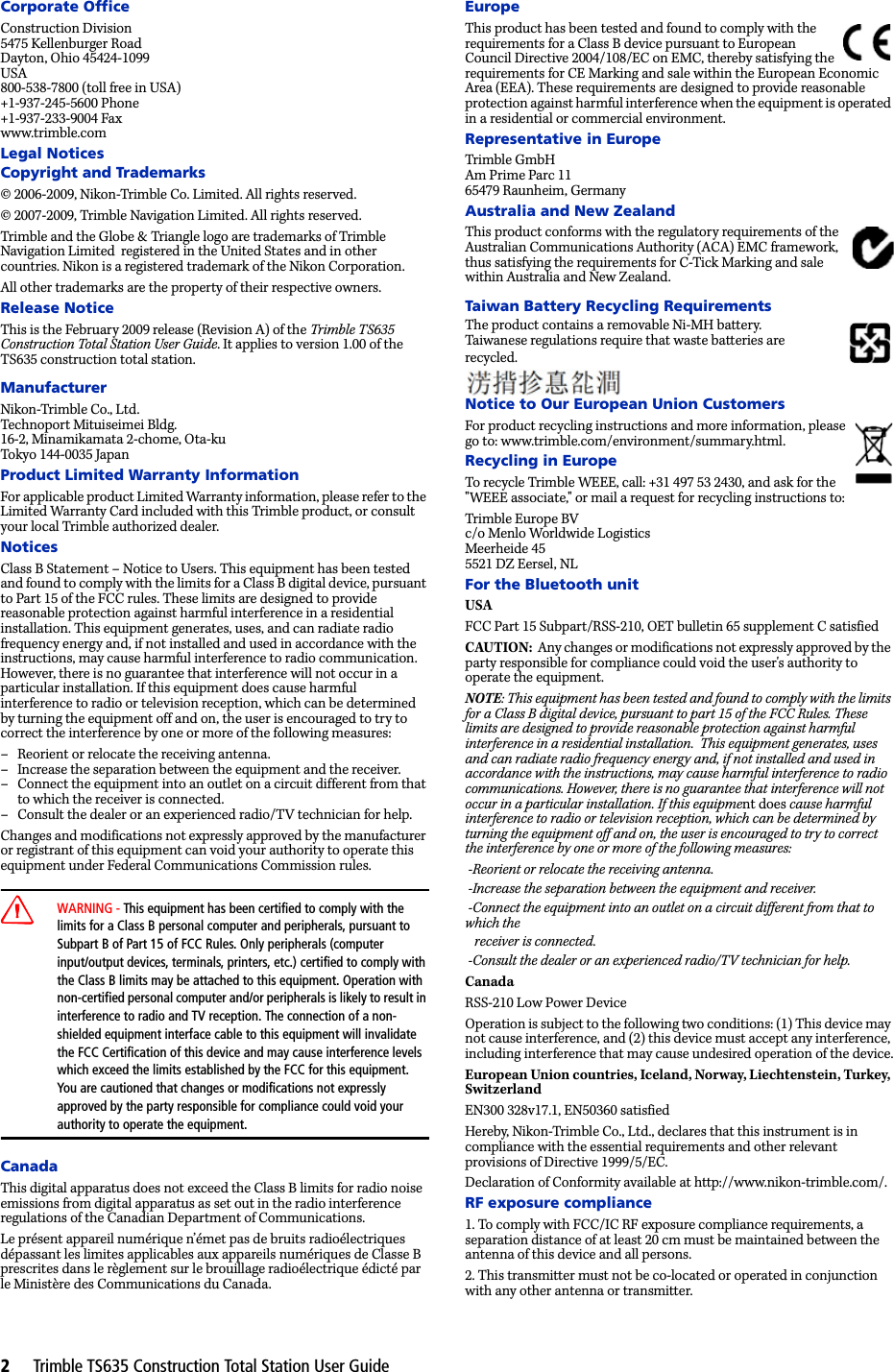
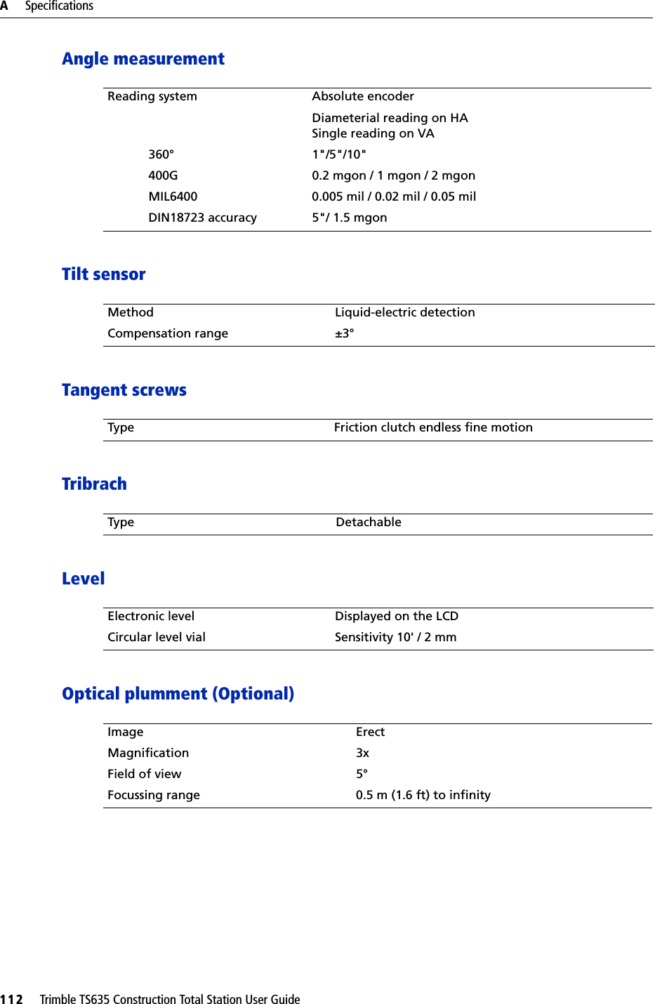
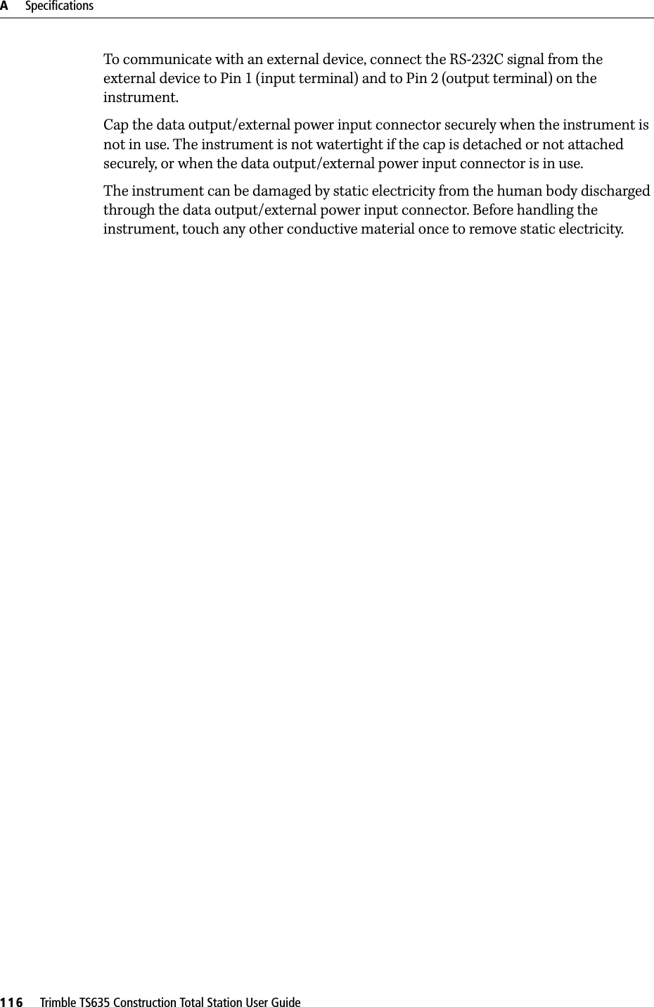
![4 Applications58 Trimble TS635 Construction Total Station User Guide6. Enter the station name, the height of instrument (HI), and a feature code (CD) if required. The station name defaults to the last recorded PT + 1.7. Backsight (BS) defaults to the first point (P1). To change the selected point, highlight the BS field and then select the Change softkey.8. To finish the setup and record the station, press [ENT] in the BS field.KnownSelect this option to set up a station with known coordinates or azimuth.1. Press [2] or select Known in the Stn Setup menu.2. Enter a point name or number in the ST field.–If the input point number or name is an existing point, its coordinates are displayed and the cursor moves to the HI (Height of instrument) field.–If the point is new, a coordinate input screen appears. Enter the coordinates for the point. Press [ENT] after each field. When you press [ENT] in the CD field, the new point is stored.–If the specified point has a code, the code appears in the CD field.3. Enter the instrument height in the HI field and then press [ENT]. 4. In the Backsight screen that appears, select an input method for defining the backsight point: –To sight the backsight by entering coordinates, see the following section.–To sight the backsight by entering the azimuth and angle, see page 59.Sighting the backsight by entering coordinatesZYX0XXbY0 YbBacksight point(Xb, Yb, Zb)Station point(Xi, Yi, Zi)Instrument height](https://usermanual.wiki/NIKON-TRIMBLE/NT0001.Host-3-user-manual-2-of-2/User-Guide-1089797-Page-12.png)
![Trimble TS635 Construction Total Station User Guide 59Applications 41. To enter coordinates for the backsight point (BS), press [1] or select Coord from the Backsight screen.2. Enter the point name. If the point exists in the job, its coordinates are shown.3. If you intend to take a distance measurement to the BS, enter the height of target in the HT field.4. Sight the BS, and then press [ENT] to complete the setup.If measuring to a known coordinate BS, press [DSP] to display a QA screen. The QA screen shows the dHD and dVD values, which indicate the difference between the measured distance and the distance calculated from the known coordinates.5. To record the station, press [ENT].6. To finish the station setup after taking a distance measurement, press [ENT]. Sighting the backsight by entering the azimuth angle1. To enter the azimuth angle to the backsight point, press [2] or select Angle from the Backsight screen.2. If there is no point name for the BS, press [ENT] on the BS field.HA Azimuth calculated by coordinatesBacksight pointAzimuthStation point(Xi, Yi, Zi)Instrument heightXY0Y](https://usermanual.wiki/NIKON-TRIMBLE/NT0001.Host-3-user-manual-2-of-2/User-Guide-1089797-Page-13.png)
![4 Applications60 Trimble TS635 Construction Total Station User Guide3. In the HA field, enter the azimuth angle to the BS point.If you press [ENT] without entering a value in the HA field, the azimuth is automatically set to 0°00'00".4. Sight the BS point and press [ENT]. Base XYZSelect this option to change the instrument XYZ values.Base XYZ does not store an ST record in the job, so the BS Check cannot check the backsight if you enter a station using the Base XYZ option.You can use this function without an open job. 1. Press [3] or select Base XYZ from the Stn Setup menu.The current instrument XYZ values are shown as the default.2. Enter the new instrument XYZ values and then press [ENT].3. Do one of the following:–To reset the horizontal angle, enter a value in the HA field and then press [ENT].–If you do not need to reset the horizontal angle, leave the HA field blank and then press [ENT].The Stn Setup menu appears.Remote BMSelect this option to determine the station elevation.1. Press [4] or select Remote BM from the Stn Setup menu.2. Enter the BM point and press [ENT]. The point appears briefly. The cursor then moves to the HT field.3. Enter the HT and then press [ENT].](https://usermanual.wiki/NIKON-TRIMBLE/NT0001.Host-3-user-manual-2-of-2/User-Guide-1089797-Page-14.png)
![Trimble TS635 Construction Total Station User Guide 61Applications 44. Sight the Bench Mark point and then press [MSR1] or [MSR2].The updated station coordinates are displayed. You can change the HI in this screen.5. To record the updated STN, press [ENT].When the HI setting is changed, the Z coordinate is updated before the station is recorded.You must complete a station setup before you use the Remote Benchmark function.BS CheckSelect these options to check and reset the backsight direction.Note – Complete a station setup before using the BS check function.This function always refers to the backsight point from the last station (ST) record stored in the current open job.1. Press [5] or select BS Check in the Stn Setup menu. The HA field refers to the current HA reading, and the BS field refers to the BS in the last station setup. Enter station coordinates for observations without recording data.2. Do one of the following:–To reset the horizontal angle to the HA set in the last station setup, sight the BS and then select the Reset softkey or press [ENT].–To cancel the process and return to the BMS, select the Abrt softkey or press [ESC].](https://usermanual.wiki/NIKON-TRIMBLE/NT0001.Host-3-user-manual-2-of-2/User-Guide-1089797-Page-15.png)
![4 Applications62 Trimble TS635 Construction Total Station User GuideLayout menuTo access the Layout menu, press [L-O] in the BMS.To select a command from the Layout menu, press the corresponding number key. Alternatively, press [^] or [v] to highlight the command and then press [ENT]. The last function used is highlighted.There are four layout options:•L-O to Point, page 62•L-O from Line, page 63•L-O from Arc, page 64•XYZ, page 65L-O to PointUse this method to lay out a point based on the down, out, and dZ location to a specified line.1. Press [1] or select L-O to Point from the Layout menu.2. Enter the first point (P1) along the line.Alternatively, select the MSR softkey to measure a point.If you press [ENT] without entering a PT name, you can enter temporary coordinates. Temporary coordinates are not recorded in the job.3. Enter the second point (P2) along the line.4. Enter offsets to the line.To enter the value 0.0000, press [ENT] in a blank field.5. Rotate the instrument until the dHA is close to 0°00'00".6. Sight the target, and then press [MSR1] or [MSR2].Sta Distance from P1 along the lineO/S Distance perpendicular to the line(+) Right side of the P1−P2 line(-) Left side of the P1−P2 linedZ Difference in height from the line](https://usermanual.wiki/NIKON-TRIMBLE/NT0001.Host-3-user-manual-2-of-2/User-Guide-1089797-Page-16.png)
![Trimble TS635 Construction Total Station User Guide 63Applications 4When a distance measurement is taken, the difference between the measured point and the design point appears.7. To record the point as an SO record, press [ENT].Note – Press [DSP] to switch between display screens. See also page 83.The following figure shows the terminology used to guide you to the required point. L-O from LineSelect this option to measure distance and offset values along a specified line.1. Press [2] or select L-O from Line from the Layout menu.2. Enter the first point for the reference line. Alternatively, select the MSR softkey to measure a point.If you press [ESC] in the Record PT screen, the measured point is used but not recorded in the job.3. Enter the second point for the reference line.4. Enter an asterisk ( for example, A*) in the PT field to perform a wildcard search. A list of matching points appears. Highlight a point in the list and then press [ENT].FillOutCutLRIn In OutRLFillCut](https://usermanual.wiki/NIKON-TRIMBLE/NT0001.Host-3-user-manual-2-of-2/User-Guide-1089797-Page-17.png)
![4 Applications64 Trimble TS635 Construction Total Station User GuideThe following figure shows how to determine or input a location relative to a line used for Layout.5. Sight the prism or reflective sheet and press [MSR1] or [MSR2].Note – Press [DSP] to switch between display screens. See also page 83.L-O from ArcSelect this option to measure distance and offset values on the arc-curve.1. Press [3] or select L-O from Arc from the Layout menu.2. Enter the start of the curve point (P1) and the azimuth of its tangent line (HA1).Alternatively, to enter P1 by direct measurement, select the MSR softkey.3. Choose a method to define the curve.P2 can be any point on the tangent line that is to exit the curve.4. In the radius (Rad) field, enter a positive value for a clockwise curve. Enter a negative value for a counter-clockwise curve.Dwn Horizontal distance from P1 to the measured point along the P1-P2 line 6.Out Horizontal offset from the P1-P2 line to the measured pointdZ Vertical offset from the P1-P2 line to the measured pointPlain view Side viewPT1PT2Dwn OutPrismPrism PT2DwnPT1dZ](https://usermanual.wiki/NIKON-TRIMBLE/NT0001.Host-3-user-manual-2-of-2/User-Guide-1089797-Page-18.png)
![Trimble TS635 Construction Total Station User Guide 65Applications 4Once you entered all factors, the TS635 Construction Total Station calculates the curve. If the curve length (Len) is too large for a circle of the given radius, the curve is shortened.Note – Press [DSP] to switch between display screens. See also page 83.XYZSelect this option to specify the layout point by coordinates.1. Press [4] or select XYZ in the Layout menu.2. Do one of the following:–Enter the point name that you want to establish and then press [ENT].–Specify the point by code or radius from the TS635 Construction Total Station. If several points are found, they are displayed in a list. Press [^] or [v] to move up and down the list. Use [<] to move up one page, or [>] to move down one page.3. Highlight a point in the list and then press [ENT].The delta angle and the distance to the target are shown.4. Rotate the instrument until the dHA is close to 0°00'00". Press [MSR1] or [MSR2].dHA Difference in horizontal angle to the target pointHD Distance to the target point](https://usermanual.wiki/NIKON-TRIMBLE/NT0001.Host-3-user-manual-2-of-2/User-Guide-1089797-Page-19.png)
![4 Applications66 Trimble TS635 Construction Total Station User Guide5. Ask the rod person to adjust the target position. When the target is on the intended position, the displayed errors become 0.000 m (0.000 ft).Once a measurement is taken, the Cut/Fill value and Z coordinate are updated as the VA is changed.6. To record the point, press [ENT]. The PT field defaults to the specified PT + 1000.Press [MENU] and then select Settings / Rec.Use the Add Constant field to specify an integer. The integer is added to the point number that is being laid out to generate a new number for recording the layout point. The default value is 1000. For example, when you stake out PT3 with an Add Constant of 1000, the default value in the SO field (layout record) is 1003.The display then returns to the observation screen. Press [ESC]. The display returns to the PT/CD/R input screen. If you entered the stakeout point using a single point name, the PT defaults to the last PT + 1.7. If you selected a point from the list, the display returns to the list, unless all points have been selected. Press [ESC] to return to the point input screen.dHA Difference in horizontal angle to the target pointR/L Right/Left (Lateral error)IN/OUT In/Out (Longitudinal error)CUT/FIL Cut/Fill](https://usermanual.wiki/NIKON-TRIMBLE/NT0001.Host-3-user-manual-2-of-2/User-Guide-1089797-Page-20.png)
![Trimble TS635 Construction Total Station User Guide 67Applications 4Advanced feature: Specifying a layout list by inputting points by range1. Select the Fr/To softkey when the PT field is selected.2. Enter the start point (Fr) and the end point (To). The range between Fr and To must be less than 1001 points.–If existing points are found between Fr and To, a point list appears. To highlight a point in the list, press [^] or [v]. To go to the layout observation screen, press [ENT]. –If you have assigned a control job, and additional points are found in the control job, the Ctrl softkey appears under the list.Programs menuTo access the Programs menu, press [PRG] in the BMS.To select a command from the Programs menu, press the corresponding number key. Alternatively, press [^] or [v] to highlight the command and then press [ENT]. The last function used is highlighted.The Programs menu has the following options:•RDM (Radial), page 69•RDM (Cont), page 69•REM, page 70•V-Plane, page 70•Cogo, page 71](https://usermanual.wiki/NIKON-TRIMBLE/NT0001.Host-3-user-manual-2-of-2/User-Guide-1089797-Page-21.png)
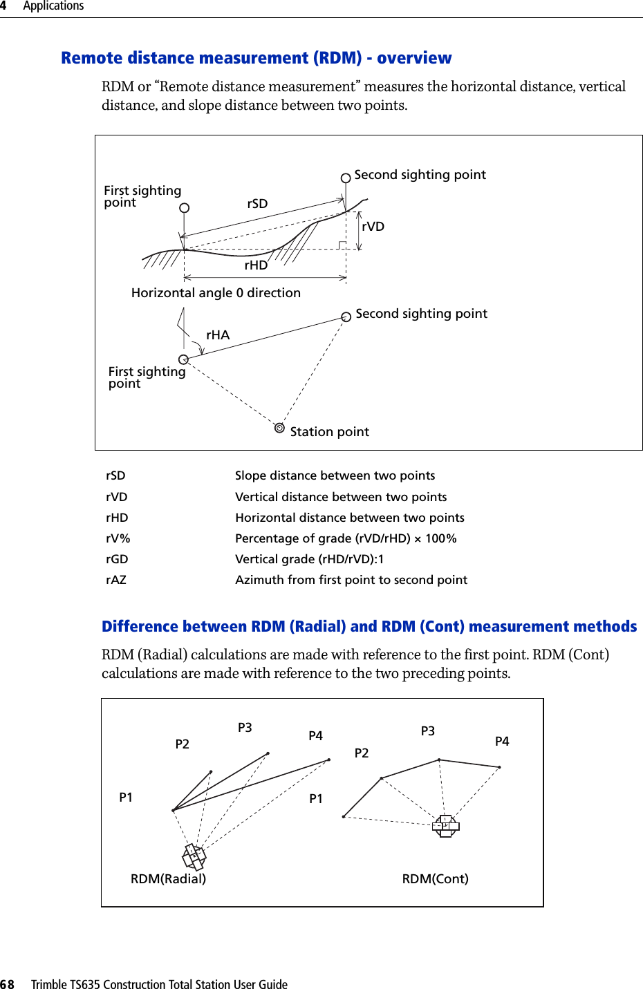
![Trimble TS635 Construction Total Station User Guide 69Applications 4RDM (Radial)Choose this option to measure between the current point and the first point measured.1. Press [1] or select RDM(Radial) in the Programs menu.2. Sight the first point and press [MSR1] or [MSR2].The distance from the station point to the first point appears.3. Sight the second point and press [MSR1] or [MSR2]. The distances between the first and second point are displayed.4. To change display screens, press [DSP]. 5. Press [ESC] to exit.RDM (Cont)Choose this option to measure between the current point and the immediately preceding point.1. Press [2] or select RDM(Cont.)from the Programs menu.2. Follow the procedure as for a radial RDM measurement. See also RDM (Radial), page 69.rSD Slope distance between two pointsrVD Vertical distance between two pointsrHD Horizontal distance between two pointsrHA Azimuth from first point to second pointrV% Percentage of grade (rVD/rHD) × 100%rGD Vertical grade (rHD/rVD): 1](https://usermanual.wiki/NIKON-TRIMBLE/NT0001.Host-3-user-manual-2-of-2/User-Guide-1089797-Page-23.png)
![4 Applications70 Trimble TS635 Construction Total Station User GuideREMChoose this option to measure a remote elevation.Note – A prism is required only at the sighting (target) point.1. Press [3] or select REM in the Programs menu.2. Enter the height of the target.3. Sight the target point and press [MSR1] or [MSR2].4. Loosen the vertical clamp and then turn the telescope to aim at an arbitrary point.The difference in elevation (Vh) appears.5. Press [ESC] to exit.V-PlaneChoose this option to measure distance and offset values in the vertical plane, using the 2-Pt Reference Plane function.1. Press [4] or select V-Plane in the Programs menu.2. Enter the first point in the vertical plane:Station pointSighting pointArbitrary pointBaseline](https://usermanual.wiki/NIKON-TRIMBLE/NT0001.Host-3-user-manual-2-of-2/User-Guide-1089797-Page-24.png)
![Trimble TS635 Construction Total Station User Guide 71Applications 4a. To enter the first point by direct measurement, select the MSR softkey. A temporary observation screen appears.b. Press [MSR1] or [MSR2]. The Record PT screen appears.c. Enter a value in the PT and CD fields, and then press [ENT].3. Enter the second point in the vertical plane. To do this, repeat Step 2.Once the plane is defined, the calculated Dwn and dZ values are updated as you move the telescope. No distance measurement is required.Note – Press [DSP] to switch between display screens. See also page 83.4. Press [ESC] to exit this function.Cogo Choose the Cogo option to perform coordinate geometry (Cogo) calculations. To open the Cogo menu, press [5] on the Programs menu.There are five items in the Cogo menu:•Inverse, page 72•Input, page 74•Area & Perm, page 76•Down+Out, page 77•Intersection, page 78Dwn Horizontal distance from P1 to the target point along the baselinedZ Vertical distance from P1 to the target point](https://usermanual.wiki/NIKON-TRIMBLE/NT0001.Host-3-user-manual-2-of-2/User-Guide-1089797-Page-25.png)
![4 Applications72 Trimble TS635 Construction Total Station User GuideInverseChoose this option from the Cogo menu to calculate angle and distance between two coordinates.Press [1] or select Inverse in the Cogo menu. The Inverse menu appears.PT-PT inversePT-PT calculates the distance and the angle between two input points. To calculate a PT–PT inverse:1. Press [1] or select PT-PT in the Inverse menu.2. Enter the first point number or name, and then press [ENT].If you press [ENT] without entering a point name, a coordinate input screen appears, and you can enter coordinates. These coordinates are not stored to the database. If you want to store the point, specify a new point name.3. Type the second point number/name, and then press [ENT]. If necessary select the MSR softkey to shoot the point on the spot so that you can use it in the calculation.The azimuth, horizontal distance, and vertical distance from the first point to the second point are displayed.4. Do one of the following:–To return to the PT input screen, press [ESC].–To return to the Cogo menu, press [ENT].–To change the contents of the result screen, press [DSP].Gd Grade (HD/VD)V% 100/GdrSD Slope distance PT1 to PT2](https://usermanual.wiki/NIKON-TRIMBLE/NT0001.Host-3-user-manual-2-of-2/User-Guide-1089797-Page-26.png)
![Trimble TS635 Construction Total Station User Guide 73Applications 43Pt AngleIf you choose 3Pt Angle, the TS635 Construction Total Station calculates the angle between two lines defined by three points. To calculate a 3Pt angle:1. Press [2] or select 3Pt Angle from the Inverse menu. P1 is the base point. Two lines are to be defined by P2 and P3, both from P1.2. Enter the P1 point name. Alternatively, use the MSR softkey to take a measurement to the point.3. Enter the second point (P2) to define the baseline, P1–P2. The angle (dHA) is measured from the baseline.4. Enter the third point (P3) to define the second line, P1–P3.When you press the MSR softkey, a temporary measuring screen appears. Sight the target and press [MSR1] or [MSR2] to take a measurement.After the measurement, a recording point screen appears. To store the measured point, enter the PT, HT, and CD values and press [ENT]. To use the point without recording it, press [ESC].When you have entered three points, the instrument calculates the angle and distances.5. Do one of the following:–To return to the Inverse menu, press [ENT].–To return to the Input BasePt screen, press [ESC].](https://usermanual.wiki/NIKON-TRIMBLE/NT0001.Host-3-user-manual-2-of-2/User-Guide-1089797-Page-27.png)
![4 Applications74 Trimble TS635 Construction Total Station User GuideInputChoose this option from the Cogo menu to calculate and manually input coordinates.To enter the Input menu, press [2] or select Input from the Cogo menu. There are three functions in this menu for recording new coordinate points.Azimuth+HD inputTo calculate a coordinate by an angle and distance input from the base point (P1), press [1] or select HA+HD from the Input menu.Enter the base point, P1. Type the point name and press [ENT].Enter the azimuth, horizontal distance, and vertical distance. Then press [ENT].For example, to enter 123°45'45", type 123.4545 and then press [ENT].If you do not enter a value in the dVD field, the value 0.0000 is used.A recording point screen with the calculated coordinates appears. The PT field defaults to the last recorded point + 1.Press [ENT] to store the point.TraverseTo calculate a new point based on two defined points and the angle, horizontal and vertical distances from the line defined by those two points, use the Traverse (2Pt Angle) function.Press [2] or select Traverse in the Input menu.](https://usermanual.wiki/NIKON-TRIMBLE/NT0001.Host-3-user-manual-2-of-2/User-Guide-1089797-Page-28.png)
![Trimble TS635 Construction Total Station User Guide 75Applications 4To enter P1 and P2, enter point names or take measurements to targets.Enter the plus-minus angle, horizontal distance, and vertical distance from the baseline defined by P1–P2.If you do not enter a value in the dVD field, the value 0.0000 is used.When you press [ENT] in the dVD field, a new point is calculated. The name in the PT field defaults to the last recorded point, + 1. To record the new point and return to the point input screen, press [ENT]. P1 (the base point) defaults to the previously recorded point value. P2 defaults to the previous P1 value.BTip – To continuously calculate a new point, enter +Ang, HD, and dVD from the previous bearing line. This is a convenient way to enter Traverse points.Entering coordinatesTo manually enter the XYZ coordinates, press [3] or select Input XYZ from the Input menu.The PT name defaults to the last recorded PT + 1.Enter the coordinates using the numeric keys. To move to the next field, press [ENT] or [v] in a field.To store the point as an MP record and return to the point input screen, press [ENT] in the Z field. The default PT is incremented to the next value.You can record NE, NEZ, or Z-only data.](https://usermanual.wiki/NIKON-TRIMBLE/NT0001.Host-3-user-manual-2-of-2/User-Guide-1089797-Page-29.png)
![4 Applications76 Trimble TS635 Construction Total Station User GuideArea & PermChoose this option from the Cogo menu to calculate area and perimeter.Press [3] or select Area & Perim in the Cogo menu. To take a measurement, enter the first point and press [ENT], or select the MSR softkey. In the upper right corner of the screen, a counter indicates how many points you have entered.To input point numbers consecutively, use the Fr/To softkey. See also Advanced feature: Entering a range of points, page 76.If you enter a new point name, you can enter new coordinates and record the point. If you do not want to record the point, press [ENT] without entering a value in the PT field. An XY coordinate input screen appears.Continue to enter points until you have defined all the points in the lot. Then, press [v] to calculate the area and perimeter.The first and last points that you enter are joined to close the area. You must enter the points in the order in which they define the lot. You can enter up to 99 points.Press [ENT] to exit from the function, or press [ESC] to return to the previous screens one by one.Advanced feature: Entering a range of pointsTo quickly enter a sequential range of points, use the range input function. To access this function, select the Fr/To softkey in the No. 01 or No. 02 input screens.Enter the start point name in the Fr field and the end point name in the To field. You can include letters and hyphens in the point names, but the last character must be numeric.](https://usermanual.wiki/NIKON-TRIMBLE/NT0001.Host-3-user-manual-2-of-2/User-Guide-1089797-Page-30.png)
![Trimble TS635 Construction Total Station User Guide 77Applications 4To start searching for matching points, press [ENT] in the To field. The counter shows the number of matching points found.When the search is complete, you are returned to the Input PT screen.Select the Calc softkey to calculate the area and perimeter, or enter point names in the PT field.Press [ESC] to return to the Input PT screen where the preceding point name appears.Note – If you search for a point when a control job is specified, and the system cannot find the point in the current job, the control job is also searched. If the point is found in the control job, it is copied to the current job as a UP record. See also Setting the control job, page 89.Down+OutChoose this option from the Cogo menu to calculate coordinates from Down and Out.Press [4] or select Down & Out in the Cogo menu. Enter the base point (P1). Specify the azimuth bearing. To do this, enter a value in the HA or P2 field. P2 is a second point on the line.Enter the horizontal distance along the baseline (Dwn), the horizontal distance perpendicular to the line (Out), and the vertical distance (dVD).HAP2P1](https://usermanual.wiki/NIKON-TRIMBLE/NT0001.Host-3-user-manual-2-of-2/User-Guide-1089797-Page-31.png)
![4 Applications78 Trimble TS635 Construction Total Station User GuideA negative value in the Dwn field means the opposite direction along the defined bearing line.A negative value in the Out field is for the left-hand side of the bearing line.To calculate the coordinates of the point (PM), press [ENT] in the dVD field. You can change the Z coordinate here.To record the point, press [ENT] in the CD field. The coordinates are stored as a CC record. IntersectionChoose this option from the Cogo menu to calculate coordinates using intersection functions.Press [5] or select Intersection in the Cogo menu. The Intersection menu appears. It has four functions for calculating coordinates.Out(-)Dwn(-)Out(+)Dwn(+)](https://usermanual.wiki/NIKON-TRIMBLE/NT0001.Host-3-user-manual-2-of-2/User-Guide-1089797-Page-32.png)
![Trimble TS635 Construction Total Station User Guide 79Applications 4Calculating a bearing-bearing intersectionA bearing-bearing intersection is the intersection point of two lines. To calculate a bearing-bearing intersection:1. Press [1] or select Brng-Brng in the Intersection menu. 2. Enter the first point name and press [ENT]. Alternatively, to measure directly to the point, select the MSR softkey. 3. Define the first line by azimuth.4. To define the line by two points, select the Pts softkey. The Fr field defaults to the P1 point, but you can change the selected point. In the To field, enter or measure to the second point.See also Advanced feature: Entering angle and distance offsets, page 82.5. Do one of the following:–To return to the previous screen, press [ENT]. The calculated value appears in the HA field. –To go to the next screen, press [ENT]. 6. Define the second line by two points or by P2 and HA.7. To calculate the coordinates of the intersection point, press [ENT] in the HA field. The calculated coordinates are displayed. You can input a Z coordinate if necessary.8. Enter a value in the PT field and in the CD field. 9. To record the point, press [ENT].](https://usermanual.wiki/NIKON-TRIMBLE/NT0001.Host-3-user-manual-2-of-2/User-Guide-1089797-Page-33.png)
![4 Applications80 Trimble TS635 Construction Total Station User GuideCalculating a bearing-distance intersection1. Press [2] or select Brng-Dist in the Intersection menu.Brng-Dist calculates the intersection point formed by one line and one distance (radius).2. Enter a point on the line.The line can be defined by two points or by a point and an azimuth.3. Enter the second point (P2) as the center of the circle.4. Enter the distance from P2:–To define the distance (HD) by two points, select the Pts softkey.–To calculate the coordinates of the intersection point, press [ENT] in the HD field. 5. If there are two results, the first solution appears graphically relative to the P1–P2 line. To display the second solution, press [<] or [>].6. To record the point, press [ENT] when the required solution appears.7. Enter a Z coordinate if necessary. 8. To move to the PT and CD fields, press [ENT].](https://usermanual.wiki/NIKON-TRIMBLE/NT0001.Host-3-user-manual-2-of-2/User-Guide-1089797-Page-34.png)
![Trimble TS635 Construction Total Station User Guide 81Applications 4Calculating a distance-distance intersection1. Press [3] or select Dist-Dist in the Intersection menu.2. Enter the first point name and press [ENT], or select the MSR softkey to measure directly to the point.3. Enter the distance from P1 and press [ENT].4. To define the distance (HD) by two points, select the Pts softkey.5. Enter P2 and the distance from P2 (HD).6. To calculate the coordinates of the intersection point, press [ENT] in the HD field.7. Press [<] or [>] to display the second solution.8. To record the point, press [ENT] when the required solution appears.9. Enter a Z coordinate if necessary.10. Press [ENT] to move to the PT and CD fields.Calculating a point-line intersection1. Press [4] or select Pt-Line in the Intersection menu.2. Enter the first point name and press [ENT], or select the MSR softkey to measure directly to the point.3. Enter the azimuth, or select the Pts softkey to enter another point name on the line.](https://usermanual.wiki/NIKON-TRIMBLE/NT0001.Host-3-user-manual-2-of-2/User-Guide-1089797-Page-35.png)
![4 Applications82 Trimble TS635 Construction Total Station User Guide4. Enter the perpendicular point to the line, or select the MSR softkey to take a measurement to the point.5. To calculate the coordinates of the intersection point, press [ENT].If P1 and P2 are 3D points, the Z coordinate of the perpendicular point is calculated relative to the P1–P2 slope.6. Enter PT and CD then press [ENT] to record the point.Advanced feature: Entering angle and distance offsetsTo display the offset input screen, select the O/S softkey.In the Ang field, enter a positive value to rotate the line clockwise. Enter a negative value to rotate the line counter clockwise.In the O/S field, enter a positive value to specify an offset to the right. Enter a negative value to specify an offset to the left.](https://usermanual.wiki/NIKON-TRIMBLE/NT0001.Host-3-user-manual-2-of-2/User-Guide-1089797-Page-36.png)
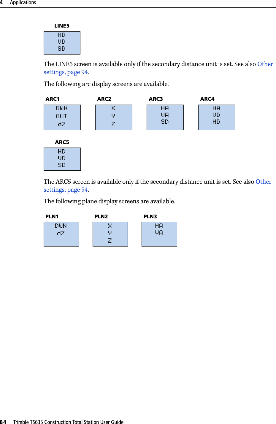
![Trimble TS635 Construction Total Station User Guide 83Applications 4Recording measurement dataTo record points from any observation screen, press [ENT].PT defaults to the last recorded PT, + 1.You can enter the PT name from the point list or the point stack. See Entering a point from the point list, page 49, and Entering a point from the point stack, page 49.To record the point, press [ENT] on the last field.If HA or VA is moved after you take a measurement, but before you press [ENT], the recalculated coordinates will be stored.If the point name that you want to record already exists in the job, an error message appears. Depending on the type of existing record, you can overwrite the old record with the new data. See Recording data, page 125.If you do not need to record data, press [MENU] and set Settings / Rec to OFF.The default setting is OFF.Switching between display screensPress [DSP] to switch between display screens. See the [DSP] button, page 40. Each time you press [DSP], the next screen appears. When you press [DSP] in the final screen, the first screen appears.The following line display screens are available.LINE1 LINE2 LINE3 LINE4dOWNOUTdZXYZHAVASDHAVDHD](https://usermanual.wiki/NIKON-TRIMBLE/NT0001.Host-3-user-manual-2-of-2/User-Guide-1089797-Page-37.png)
![CHAPTER5Trimble TS635 Construction Total Station User Guide 85Menu Screen 5In this chapter:QJobQSettings (basic job settings)QDataQCommunicationQ1sec-KeyQCalibrationQTimeUse the MENU screen to access functions and settings. To display the MENU screen, press the [MENU] key.](https://usermanual.wiki/NIKON-TRIMBLE/NT0001.Host-3-user-manual-2-of-2/User-Guide-1089797-Page-39.png)
![5 Menu Screen86 Trimble TS635 Construction Total Station User GuideJobUse the Job option to open, create, delete, and manage jobs. To open the Job Manager, press [1] or select Job from the MENU screen.If jobs are stored on the TS635 construction total station, the job list appears. It shows all the stored jobs with the newest job at the top of the list. See Opening an existing job, page 86.If no jobs are stored, the Create Job screen appears. See Creating a new job, page 86.Opening an existing jobThe job list shows all the jobs stored on the instrument, in descending date order.The following symbols provide extra information about jobs:Press [^] to move up or [v] to move down the job list. Press [ENT] to open the highlighted job.When you open a job, all job settings are automatically changed to match those used in the open job.Creating a new job1. Select the Creat softkey in the job list.2. Enter a job name of up to eight characters. Select [ENT].3. Do one of the following:Symbol Meaning* Current job@ Control job! Some of the job settings are different from the current job](https://usermanual.wiki/NIKON-TRIMBLE/NT0001.Host-3-user-manual-2-of-2/User-Guide-1089797-Page-40.png)
![Trimble TS635 Construction Total Station User Guide 87Menu Screen 5–To check the job settings, select the Sett softkey.–To create a new job using the current job settings, press [ENT] or select the OK softkey.Job settingsJob settings are separate from other temporary settings.Job settings are established when a job is created, and cannot be changed. This ensures that the data in a job is correctly stored in the database, and that all necessary corrections are applied when you store each record. To move between fields, press [^] or [v]. Alternatively, to move to the next field, press [ENT]. To change the setting in the selected field, press [<] or [>]. To confirm the job settings and create the job, press [ENT] in the last field.Screen 1 Screen 2Scale Factor 0.999600 to 1.000400 T-P correction ON / OFFSea Level ON / OFFC&R correction OFF / 0.132 / 0.200Angle unit DEG / GON /MILDistance unit Metre / US-Ft / I-FtTemp unit °C / °FPress unit hPa / mmHg / inHg](https://usermanual.wiki/NIKON-TRIMBLE/NT0001.Host-3-user-manual-2-of-2/User-Guide-1089797-Page-41.png)
![5 Menu Screen88 Trimble TS635 Construction Total Station User GuideScreen 3If you select US–Ft or I–Ft, an additional settings screen appears. Use this screen to specify whether to display values in Decimal–Ft or Ft–Inch.Deleting a jobNote – There is no undelete function in Job Manager. Before you press [ENT] or select DEL, make sure that the selected job is the one that you want to delete.1. In the job list, highlight the job to delete.2. Select the DEL softkey. A confirmation screen appears.3. Do one of the following: –To delete the selected job, press [ENT] or select the DEL softkey.–To cancel the deletion and return to the previous screen, press [ESC] or select the Abrt softkey. After you delete a job, the job list appears.VA zero Zenith / HorizonOrder NEZ / ENZ](https://usermanual.wiki/NIKON-TRIMBLE/NT0001.Host-3-user-manual-2-of-2/User-Guide-1089797-Page-42.png)
![Trimble TS635 Construction Total Station User Guide 89Menu Screen 5Setting the control jobA control job has the same format as a standard job. You can open and modify it like any other job, and you can use it to record any measured data.To set the control job:1. Highlight the job that you want to use as the control job.2. Select the Ctrl softkey.A confirmation screen appears.3. Do one of the following:–To set the selected job as the control job, press [ENT] or select the Yes softkey.–To cancel the process, press [ESC] or select the No softkey.If a control job is already assigned, the newly assigned control job replaces it as the control job.To clear the selected control job, highlight the current control job in the job list and select the Ctrl softkey. Then press [ENT] or select the Yes softkey.Displaying job informationTo display job information, highlight the job name and then select the Info softkey. The Information screen shows the number of records in the job, the free space, and the date when the job was created. Free space indicates how many points can be stored in the job.To return to the job list, press any button.](https://usermanual.wiki/NIKON-TRIMBLE/NT0001.Host-3-user-manual-2-of-2/User-Guide-1089797-Page-43.png)
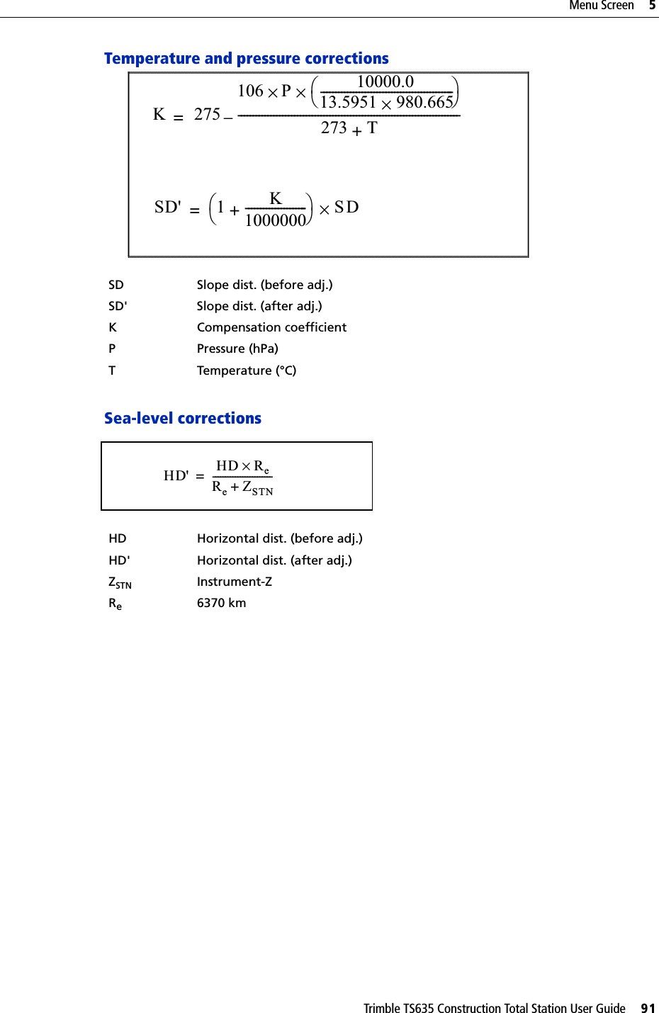
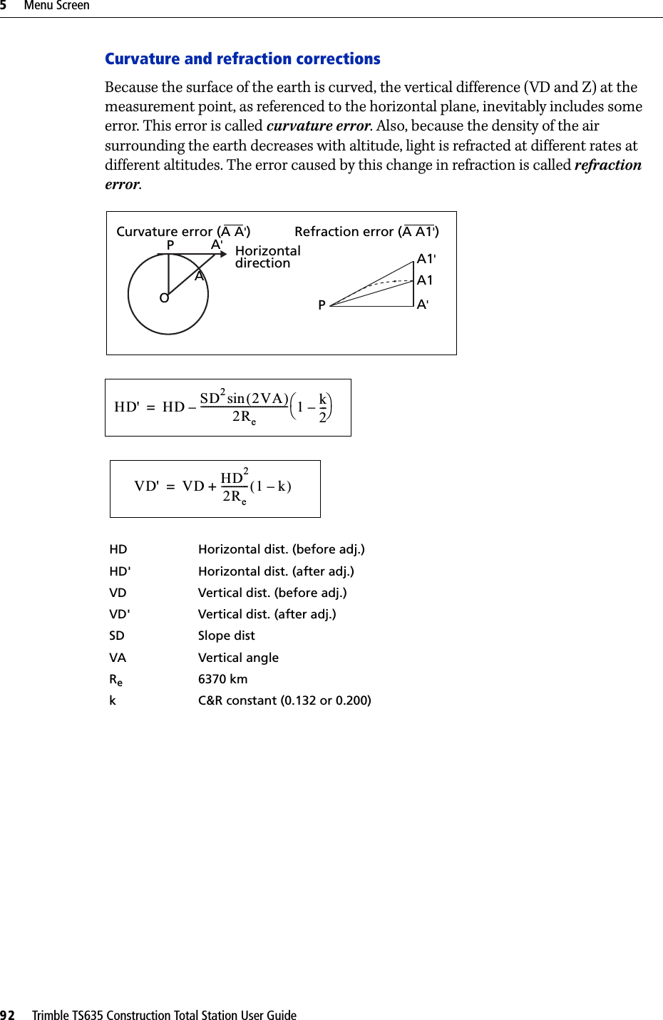
![5 Menu Screen90 Trimble TS635 Construction Total Station User GuideSettings (basic job settings)Use the Settings menu to configure the basic job settings.Press [2] or select Settings on the MENU screen.Some job settings, as identified in the following sections, cannot be changed once a job is created. If you attempt to change any of these settings while a job is open, a confirmation screen appears, asking you to create a new job with the new settings, or to work with the new settings without recording any data. See Settings, page 126.AngleTo change the angles, press [1] or select Angle in the Settings menu.The VA zero job setting cannot be changed once a job is created.DistanceThese settings cannot be changed once a job is created.To change the distance, press [2] or select Distance in the Settings menu. VA zero Zenith / Horizon Resolution 1" / 5" / 10"0.2/ 1/ 2mgon0.005 / 0.02 / 0.05 milScale Numeric value between 0.999600 and 1.000400T-P corr ON / OFFSea Level ON / OFFC&R corr OFF / 0.132 / 0.200](https://usermanual.wiki/NIKON-TRIMBLE/NT0001.Host-3-user-manual-2-of-2/User-Guide-1089797-Page-44.png)
![Trimble TS635 Construction Total Station User Guide 93Menu Screen 5CoordinatePress [3] or select Coord. in the Settings menu. The Coordinate menu appears.The Order and AZ job settings cannot be changed once a job is created.CommunicationsPress [4] or select Comm. in the Settings menu. The Communication menu appears.See also Appendix B, Transferring Coordinate Data.UnitNote – The Angle, Distance, Temp, and Press job settings cannot be changed once a job is created.Press [5] or select Unit in the Settings menu. The Unit menu appears. Order NEZ / ENZ Label XYZ / YXZ / NEZ(ENZ)Ext.Comm NIKON / SETPort Serial/BluetoothBaud (bps) 1200 / 2400 / 4800 / 9600 / 19200 / 38400Length 7 / 8Parity EVEN / ODD / NONEStop bit 1 / 2Angle DEG (Degree)GON (GON)MIL (Mil6400)Distance MeterUS-FtI-FTemp °C (Celsius)°F (Fahrenheit)Pressure hPammHginHg](https://usermanual.wiki/NIKON-TRIMBLE/NT0001.Host-3-user-manual-2-of-2/User-Guide-1089797-Page-47.png)
![5 Menu Screen94 Trimble TS635 Construction Total Station User GuideIf you select US-Ft or I-Ft, an additional settings screen appears. Use this screen to specify whether to display values in Decimal-Ft or Ft-Inch.Power savingTo open the Power Save menu, press [4] or select PwrSave in the Settings menu.RecordingPress [7] or select Rec in the Settings menu. The Rec Menu appears.•If you need to record coordinate data from your observations, set the Rec Data field to ON. •If you would like to record a feature code when you record coordinate data, set the CD field to ON. The CD field appears in the Recording PT screen.•This field sets the default point number for the observed coordinate data when you select Layout / XYZ.Other settingsPress [8] or select Other in the Settings menu. The Others menu appears.Main unit OFF / 5 min / 10 min / 30 min .Sleep OFF / 1 min / 3 min / 5 minRec Data ON / OFFCD field ON / OFF Add const Integer between 1 and 999,999XYZ disp Fast / Normal / Slow / +ENT2nd Unit None / Meter / US-Ft / I-FtCD Input 123 / ABCLanguage English / French / German / Italian / DutchOwner’s Detail Up to 20 characters](https://usermanual.wiki/NIKON-TRIMBLE/NT0001.Host-3-user-manual-2-of-2/User-Guide-1089797-Page-48.png)
![Trimble TS635 Construction Total Station User Guide 95Menu Screen 5XYZ disp defines the speed to move to the next screen after showing XYZ of the input point.When the secondary unit is set to a unit, an extra display screen is available in the BMS, layout observation screens, and L–O from line screens. The extra screen shows the HD, VD, and SD in the secondary unit.If you select US-Ft or I-Ft, an additional settings screen appears. Use this screen to specify whether to display values in Decimal-Ft or Ft-Inch.The CD Input field sets the default input mode when a CD field appears.In the Language field, use [<] / [>] to open the language screen and [v] / [^] to select the required language. Press [ENT] to confirm. In the Reboot confirmation screen, press [ENT] to restart the instrument. The instrument reboots and shows the start-up screen in the selected language. Then a regional setting screen appears, in which you can quickly configure the instrument to a pre-set combination of the default regional settings. See Regional configuration, page 45.The Owner’s Detail field allows you to enter your name or the name of your company. If you enter a value in this field, it appears when you start the TS635 construction total station.DataUse the Data menu to view or edit records. To access it, press [3] on the MENU screen.Viewing coordinate dataCoordinate data appears in a list, with the newest record at the bottom of the screen. Use [^] or [v] to scroll through the records. Use [<] or [>] to move up or down one page.Press [ENT] to see more detailed information about the selected record.](https://usermanual.wiki/NIKON-TRIMBLE/NT0001.Host-3-user-manual-2-of-2/User-Guide-1089797-Page-49.png)
![5 Menu Screen96 Trimble TS635 Construction Total Station User GuideThe header (XYZ, YXZ, NEZ, or ENZ) depends on the Coord. Label setting, which is accessed by pressing [MENU] and then selecting Settings / Coord. See also Coordinate, page 93.UP, MP, CC, SS, and SO recordsAll coordinate records contain PT, CD, X, Y, and Z fields.•UP records are uploaded point coordinates. •MP records are manually input point coordinates. •CC records are points calculated in Cogo. •SS records are sideshot records stored in the BMS. •SO records are stored in layout functions. Deleting coordinate records1. In the XYZ screen, use [^] or [v] to highlight the record that you want to delete. Then select the DEL softkey.2. A confirmation screen appears.a. To delete the selected record, press [ENT] or select the Yes softkey.b. To cancel the deletion of data, press [ESC] or select the No softkey.Alternatively, delete coordinate data by selecting the DEL softkey in the detailed display screen for the record.If the record that you want to delete is referred by any station record, a confirmation message appears.Editing coordinate recordsYou can edit point, CD, and coordinate values in coordinate records. However, you cannot edit the coordinate record for the current station.](https://usermanual.wiki/NIKON-TRIMBLE/NT0001.Host-3-user-manual-2-of-2/User-Guide-1089797-Page-50.png)
![Trimble TS635 Construction Total Station User Guide 97Menu Screen 51. Do one of the following:–In the XYZ screen, use [^] or [v] to highlight the record to edit. Then select the Edit softkey.–In the detailed data screen, select the Edit softkey.2. Use [^] or [v] to highlight a field. Then modify the value in the selected field.3. When you have finished editing, press [ENT] in the CD field.A confirmation screen appears.4. Do one of the following:–To accept the changes and return to the data view screen, press [ENT] or select the Yes softkey. –To go back to the edit screen, press [ESC] or select the No softkey. Searching coordinate recordsYou can search for records by their type, point name, code, or by any combination of these values.In the XYZ screen, select the Srch softkey to access the XYZ data search function.To search for a record by point name, enter the point name in the PT field and press [ENT] twice.You can use the asterisk (*) as a wildcard. For example, when you enter 500* in the PT field, the search matches the points named 500, 500-1, 500-A, and 5000.To search for a record by point type, move to the Type field and use [<] or [>] to change the selected point type. The options are ALL, MP, UP, CC, and RE.•If more than one point matches the search criteria, the matching points are displayed in a list.Use [^] or [v] to highlight the required point. Press [ENT] to select it.Detailed data for the selected record appears. Select the DSP softkey to change the fields shown.Press [ESC] to return to the list.](https://usermanual.wiki/NIKON-TRIMBLE/NT0001.Host-3-user-manual-2-of-2/User-Guide-1089797-Page-51.png)
![5 Menu Screen98 Trimble TS635 Construction Total Station User Guide•If no point matches the specified criteria, an error screen appears. Press any button to return to the data screen.Entering coordinatesIn the XYZ screen, select the Input softkey. A new input point screen appears.The PT field defaults to the last recorded PT + 1, but you can change the value shown.Enter the PT and CD and then press [ENT] to enter coordinates.Use the numeric keys to enter the coordinates. Press [ENT] or [v] in each field to move to the next field.When you press [ENT] in the CD field, the point is stored as an MP record.After you have recording a point, the next point input screen is shown with the updated default PT.You can record NE, NEZ, or Z-only data.](https://usermanual.wiki/NIKON-TRIMBLE/NT0001.Host-3-user-manual-2-of-2/User-Guide-1089797-Page-52.png)
![Trimble TS635 Construction Total Station User Guide 99Menu Screen 5CommunicationUse the Communication menu to download or upload data. To access it, press [4] or select Comm. on the MENU screen.Downloading coordinate dataTo change the download settings, press [1] or select Download in the Communication menu.To display the total number of records that will be downloaded, press [ENT] in the Data field.As each record in the current job is output from the TS635 construction total station, the current line number is updated.Once transferring is completed, you can choose whether to delete the current job:•To delete the current job, press [4]. •To return to the Basic Measurement Screen (BMS) without deleting the current job, press [ESC] or select the Abrt softkey.Uploading coordinate dataTo upload coordinate data from a computer, press [2] or select Upload XYZ in the Communication menu. The default data format appears.To change the order of data fields, select the Edit softkey. See also Advanced feature: Editing the data order for upload, page 100.Otherwise, press [ENT].Select the Job softkey to go to the Job Manager screen. See also Job, page 86.Format NIKON (Fixed)Data Coordinate (all)Coordinate (layout records only)](https://usermanual.wiki/NIKON-TRIMBLE/NT0001.Host-3-user-manual-2-of-2/User-Guide-1089797-Page-53.png)
![5 Menu Screen100 Trimble TS635 Construction Total Station User GuideTo change the communication settings, select the Comm softkey. The serial port settings must match the settings used by the terminal software on the computer.Use an RS-232C cable to connect the TS635 construction total station to the computer. In the terminal program, set flow control to Xon/Xoff.The Free space field shows the number of points that can still be stored on the TS635 construction total station.Press [ENT] to put the TS635 construction total station in receive mode. On the computer, choose the Send Text File command in the terminal program to start sending data.As each point is received by the instrument, the value in the Records field is incremented.If you press [ESC] during data upload, the upload is canceled and the display returns to the Communication menu. Records that were received before you pressed [ESC] are stored in the job.During upload, the system will truncate any code that is longer than 16 characters.If the existing point is a UP, CC, or MP record, and it is not referred to by any station or backsight, it is automatically overwritten by the uploaded point. No error message appears.Advanced feature: Editing the data order for upload1. Select the Edit softkey. The Data Fields screen appears.2. To move between the fields, press [<] or [>].3. To change the selected item in a field, use the and softkeys. The options are PT, N, E, Z, CD, or blank.4. To save your changes and return to the previous screen, select the Save softkey.For example, if your original data is as follows:1, 30.000, 20.000, L1and you set the data fields to PT N E CD, then the uploaded data is:PT=1, N=30.000, E=20.000, CD=L1For more information about coordinate data, see Transferring coordinate data to the total station, page 118.](https://usermanual.wiki/NIKON-TRIMBLE/NT0001.Host-3-user-manual-2-of-2/User-Guide-1089797-Page-54.png)
![Trimble TS635 Construction Total Station User Guide 101Menu Screen 5Uploading coordinates without pointsYou can upload data without points. If you do not include a point in the format definition, each line of data is automatically assigned the next available point number. To help you to select points in the field, make sure that you store an identifier in the CD field.The data format cannot include duplicate items. Use PT, N, E, Z, and CD once each in the data format.To skip an item in your original file, set the corresponding field to blank.1sec-KeyUse the 1sec-Key menu to configure the settings for the one-second buttons, [MSR1], [MSR2], and [DSP].To access it, press [5] or select 1sec-Keys in the MENU screen.[MSR] button settingsThere are two [MSR] buttons: •To change the settings for the [MSR1] button, press [1] or select MSR1.•To change the settings for the [MSR2] button, press [2] or select MSR2.Each [MSR] button has four settings.In the Const and Track field, use the numeric keys to enter values. In the other fields, use [<] or [>] to change the settings.BTip – To quickly access the settings screen, hold down [MSR1] or [MSR2] for one second.[DSP] button settingsTo change the display items in the BMS and in Layout observation screens, press [2] or select [DSP] in the 1sec-Keys menu.To move the cursor, use [<], [>], [^] or [v]. To change the display item, press either the softkey or the softkey.To save the changes, press [ENT] from the last line of <DSP3> or select the Save softkey.](https://usermanual.wiki/NIKON-TRIMBLE/NT0001.Host-3-user-manual-2-of-2/User-Guide-1089797-Page-55.png)
![5 Menu Screen102 Trimble TS635 Construction Total Station User GuideBTip – To quickly access the DSP settings screen, hold down [DSP] for one second.CalibrationUse the Calibration screen to calibrate the instrument if required. To access the Calibration screen, press [6] or select Calibrat from the MENU screen.See also Adjusting the calibration, page 106.TimeUse the Date & Time screen to set the current date and time. 1. Press [7] or select Time on the MENU screen. The Date & Time screen appears.The current date and time settings are displayed.2. Enter the date in Year-Month-Day format. For example, to change the date to August 15, 2006 press [2] [0] [0] [6] [ENT] [8] [ENT] [1] [5] [ENT].If the highlighted part of the field ( for example, the year) is already correct, press [ENT] to use the current value. For example, if the date is already set to August 20, 2006, and you want to change the date to August 25, 2006, press [ENT] [ENT] [2] [5] [ENT].3. To move to the Time field, press [ENT] from the Date field:4. Enter the time in 24-hour format. For example, to set the time to 4:35 PM, press [1] [6] [ENT] [3] [5] [ENT].5. Do one of the following:–To finish setting the date and time, press [ENT] in the Minutes field. –To cancel the changes, press [ESC].](https://usermanual.wiki/NIKON-TRIMBLE/NT0001.Host-3-user-manual-2-of-2/User-Guide-1089797-Page-56.png)


![6 Checking and Adjusting106 Trimble TS635 Construction Total Station User GuideAdjusting the calibration1. Press [MENU] and [6]. The calibration screen appears.2. Take an F1 measurement to a target on the horizon. Press [ENT].The calibration fields for F1 are: The vertical angle is shown in the V0 dir= Horiz setting.When you have taken the measurement, the message on the bottom line changes from DO NOT TOUCH! to Turn to F2.3. Take an F2 measurement to the same target. Press [ENT].The TS635 construction total station has horizontal and vertical axis adjustment: When the observation on F2 is completed, four parameters are displayed.4. Do one of the following:–To return to the first observation screen, press [ESC] or select the Redo softkey. –To set parameters on the instrument, press [ENT] or select the OK softkey.5. If ACV, ACH, or Tilt is out of range, OVER appears. Press any key to return to the first observation screen.X1 Face-1 X-axis tilt valueY1 Face-1 Y-axis tilt valueVA1 Face-1 vertical angle (tilt-off value)HA1 Face-1 horizontal angle (tilt-off value)X2 Face-2 X-axis tilt valueY2 Face-2 Y-axis tilt valueVA2 Face-2 vertical angle (tilt-off value)HA2 Face-2 horizontal angle (tilt-off value)](https://usermanual.wiki/NIKON-TRIMBLE/NT0001.Host-3-user-manual-2-of-2/User-Guide-1089797-Page-60.png)

![B Transferring Coordinate Data118 Trimble TS635 Construction Total Station User GuideTransferring coordinate data to the total stationSettingsTo configure the transmission speed and other settings, press [MENU] and then select Settings / Comm. See also Communications, page 93.Record formatYou can transfer coordinate records to the TS635 construction total station in the following formats:PT ,X ,Y ,Z ,CDPTXYZCDPT ,X ,Y ,ZPTXYZPT ,X ,Y ,,CDPTXYCDPT ,X ,Y ,,PT ,X ,Y ,PT ,,,Z ,CDPT ,,,Z](https://usermanual.wiki/NIKON-TRIMBLE/NT0001.Host-3-user-manual-2-of-2/User-Guide-1089797-Page-72.png)
![Trimble TS635 Construction Total Station User Guide 119Transferring Coordinate Data BThe formats use the following codes:Data example20100,6606.165,1639.383,30.762,RKBSS20104,1165611.6800,116401.4200,00032.808020105 5967.677 1102.343 34.353 MANHOLE20106 4567.889 2340.665 33.444 PT120107 5967.677 1102.343 34.35320109,4657.778,2335.667,,PT220111,4657.778,2335.66720113 4657.778 2335.66720115,,,34.353,MANHOLE20117,,,33.444Transferring coordinate data from the total stationSettingsTo configure the transmission speed and other settings, press [MENU] and then select Settings / Comm. See also Communications, page 93.Data examplesNikon coordinate data format1,100.0000,200.0000,10.0000,2,200.0000,300.0000,20.0000,3,116.9239,216.9140,11.8425,TRAIN PLATFORM4,126.6967,206.2596,11.2539,RAMP11,100.0045,199.9958,10,0000,13,116.9203,216.9113,11.7157,14,126.6955,206.2579,10.9908,21,100.0103,199.9958,10.0000,31,100.0013,200.0005,10.0000,41,100.0224,200.0331,9.9000,43,116.9263,216,9165,11.8016,CURB44,126.7042,206.2871,10.8193,DITCH45,116.9266,216.9160,11.8028,46,126.7046,206.2845,10.8213,CP POINTCode Description LengthPT Point number Up to 20 digitsX Actual X coordinate Variable lengthY Actual Y coordinate Variable lengthZ Actual Z coordinate Variable lengthCD Feature code Up to 16 characters](https://usermanual.wiki/NIKON-TRIMBLE/NT0001.Host-3-user-manual-2-of-2/User-Guide-1089797-Page-73.png)
![Trimble TS635 Construction Total Station User Guide 123Error Messages CDataCan't Edit XYZ from measurementYou have tried to change the coordinates of an SO, SS, or CP record. You cannot change the coordinates of these records. Press any button to return to the previous screen.DELETE Stn-XYZYou have tried to delete a coordinate record that the current ST or BS refers to. You must confirm that you want to delete this record.Job managerCannot AssignYou have tried to set the current job as the control file.Press any button to return to the previous screen. Then select a different job.Can't CreateThere is no space available to create a job or record a point.Press any button to return to the Job Manager. Then select the DEL softkey to delete old jobs.Existing JobYou have entered an existing job name for a new job.Press any button and then change the name for the new job.MAX 32JobsYou are trying to create a new job when the maximum number of jobs (32) is already stored.Press any button to return to the Job Manager. Then select the DEL softkey to delete old jobs.To... Press...delete XYZ the DEL softkeyreturn to the previous screen without deleting XYZ [ESC] or the Abrt softkey](https://usermanual.wiki/NIKON-TRIMBLE/NT0001.Host-3-user-manual-2-of-2/User-Guide-1089797-Page-77.png)
![C Error Messages124 Trimble TS635 Construction Total Station User GuideLayoutInput ErrorThe point name style used in the Fr field is not the same as the style used in the To field. For example, the Fr field style is 1, and the To field style is A200.Press any button to return to the Fr/To input screen. Then re-enter the point name, using the same naming style in both fields.NO Stn SetupYou did not perform a station setup or BS check before entering the Layout function.CCAUTION – Selecting Continue does not resume the last ST record. You should only use the Continue option if you are sure that the previous ST coordinates and the current HA orientation are correct. Otherwise, records in the Stakeout function may not be correct.ProgramsNO Stn SetupCCAUTION – Selecting Continue does not resume the last ST record. You should only use the Continue option if you are sure that the previous ST coordinates and the current HA orientation are correct. Otherwise, records in the Programs function may not be correct.You did not perform a station setup or BS check before entering the Programs function.To... Press...go to the Stn Setup menu [2] or select Stn Setup return to the Basic Measurement Screen (BMS)[ESC]go to the Stakeout menu [1] or select ContinueTo... Press...go to the Stn Setup menu [2] or select Stn Setupreturn to the BMS [ESC]go to the Programs menu [1] or select Continue](https://usermanual.wiki/NIKON-TRIMBLE/NT0001.Host-3-user-manual-2-of-2/User-Guide-1089797-Page-78.png)
![Trimble TS635 Construction Total Station User Guide 125Error Messages CRecording dataDATA FULLThe data storage is full.Press any button to return to the Basic Measurement Screen (BMS). Then:DUPLICATE PTThe input PT you are trying to record already exists in the current job. An existing coordinate record cannot be overwritten by measured data.Press any button to return to the point input screen. Change the setting in the PT field.Duplicate PTThe input PT you are trying to record already exists in the current job as an SS, SO, or CP record. An existing SS, SO, or CP record can be overwritten by measured data.No Open JobNo job is open.NO Stn SetupThere is no station record in the current job, or a station setup or BS check has not been done since the program was rebooted.To... Press...delete unnecessary data [MENU] and select Datadelete jobs [MENU] and select JobTo... Press...return to the PT input screen [ESC] or the Abrt softkeyrecord RAW data and update XYZ datathe XYZ softkeyrecord RAW data only the RAW softkeyTo... Press...open the job list, if there are existing jobs[1] or select Select jobcreate a new job [2] or select Create jobreturn to the previous screen [ESC]To... Press...continue recording [1] or select Continue. If there is already an ST record in the job, the message CO, Use current orientation appears.go to the Stn Setup menu [2] or select STN Setupreturn to the previous screen [ESC]](https://usermanual.wiki/NIKON-TRIMBLE/NT0001.Host-3-user-manual-2-of-2/User-Guide-1089797-Page-79.png)
![C Error Messages126 Trimble TS635 Construction Total Station User GuideOVER RANGEYou are trying to record a coordinate with more than 13 digits.Press any button to return to the previous screen. Then check the setting for the current ST coordinate.SearchingPT Not FoundThere is no point that matches the criteria entered.Press any button to return to the point input screen.This message may appear in any function where the PT/CD is input, such as Station Setup or Stakeout.SettingsJob Settings will be changedYou have changed one or more of the following job settings:•VA zero or HA in the Angle screen (see Angle, page 90)•Scale, T-P, Sea Lvl, or C&R in the Distance screen (see Distance, page 90)•Coord or Az Zero in the Coordinates screen (see Coordinate, page 93)•Angle, Dist, Temp, or Press in the Unit screen (see Unit, page 93)Note – To record a point using the new settings, create a new job using the new settings.To... Press...discard the changes to the job settings[ESC] or the Abrt softkey. The current job remains open.close the current job and save the changes to the job settings[ENT] or the OK softkey.](https://usermanual.wiki/NIKON-TRIMBLE/NT0001.Host-3-user-manual-2-of-2/User-Guide-1089797-Page-80.png)
![Trimble TS635 Construction Total Station User Guide 127Error Messages CStation setupSame CoordinateThe input PT or coordinate is identical to the current station in STN/2:Known, or the same coordinate or point name/number is found in Resection.Press any button to return to the PT input screen. Then use a different PT.Space LOWThere is not enough space to record a station when you start any of the Station Setup functions.XY-coordinate is requiredThe input point for ST/BS does not have N/E coordinates.Press any button to return to the PT input screen. Then use a PT that has N/E coordinates.Z-coordinate is requiredThe input point for Benchmark does not have a Z coordinate.Press any button to return to the PT input screen. Then use a PT that has a Z coordinate. See page 68.System error=SYSTEM ERROR=The system has detected an internal error that is related to the lower-level system. Press any key to turn the instrument off. The system will reboot when this error is reported. If you still have more points to shoot in the site, turn the instrument on and repeat the open a job and station setup procedures.Data stored before this error will be kept safely in the Job file. If the error appears frequently, please contact your dealer or Trimble Support and report the message that appears below the =SYSTEM ERROR= line.To... Press...return to the BMS press [ESC] or select the Abrt softkey. Select the DEL softkey in Job Manager to delete old jobs.continue press [ENT] or select the OK softkey. You may not be able to record the whole process.](https://usermanual.wiki/NIKON-TRIMBLE/NT0001.Host-3-user-manual-2-of-2/User-Guide-1089797-Page-81.png)