NOFIQ Fire and Safety Systems 102040A ZigBee Fire control and indicating apparatus User Manual 1020 1000 0025 HL E v6 4
NOFIQ Fire & Safety Systems BV ZigBee Fire control and indicating apparatus 1020 1000 0025 HL E v6 4
UserManual.wiki
>
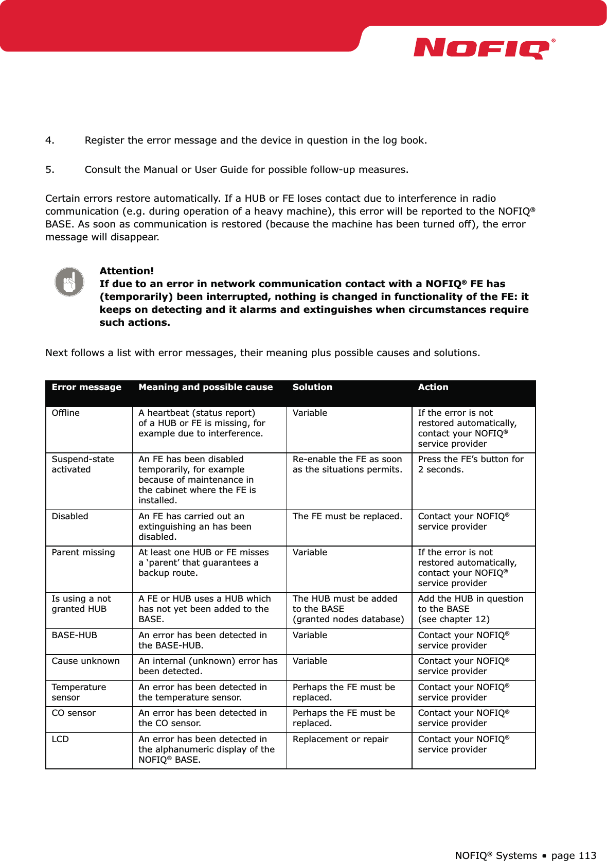
NOFIQ Fire and Safety Systems
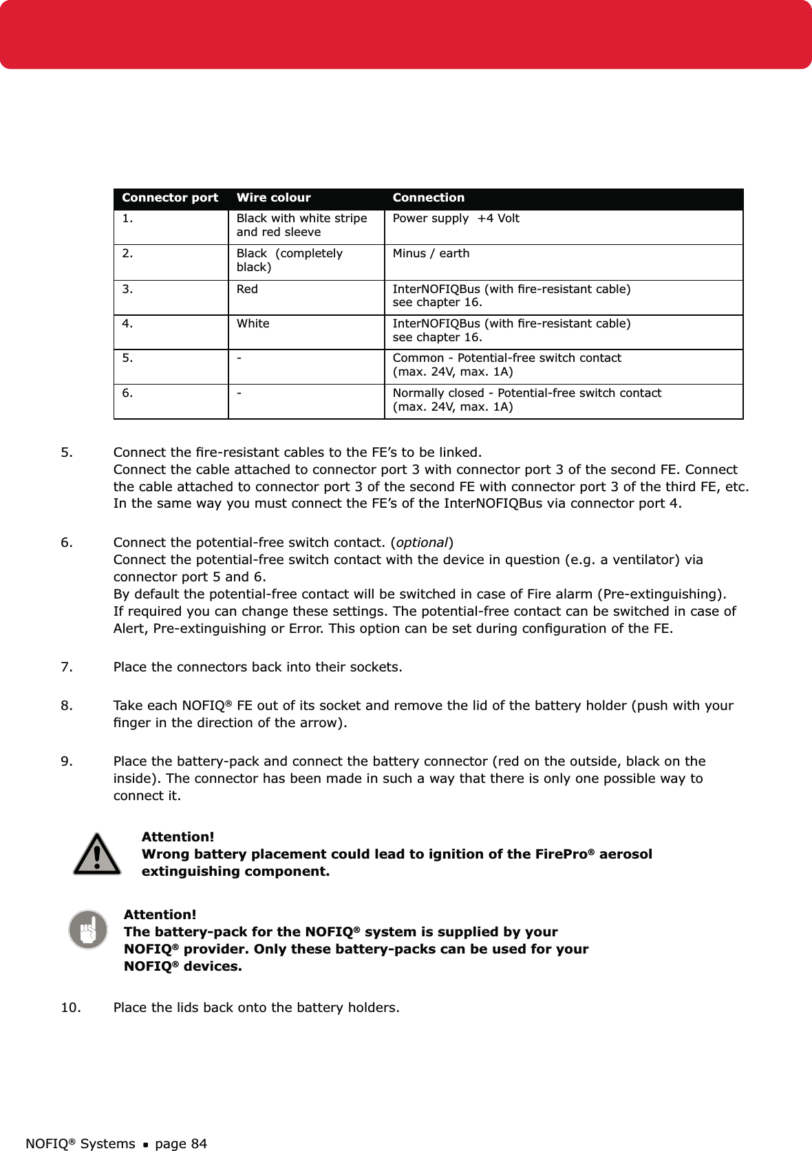
>
102040A User Manual
Users Manual
Navigation menu
Upload a User Manual
Namespaces
Wiki Guide
HTML
PDF
Info
Views
User Manual
Discussion / Help
Navigation
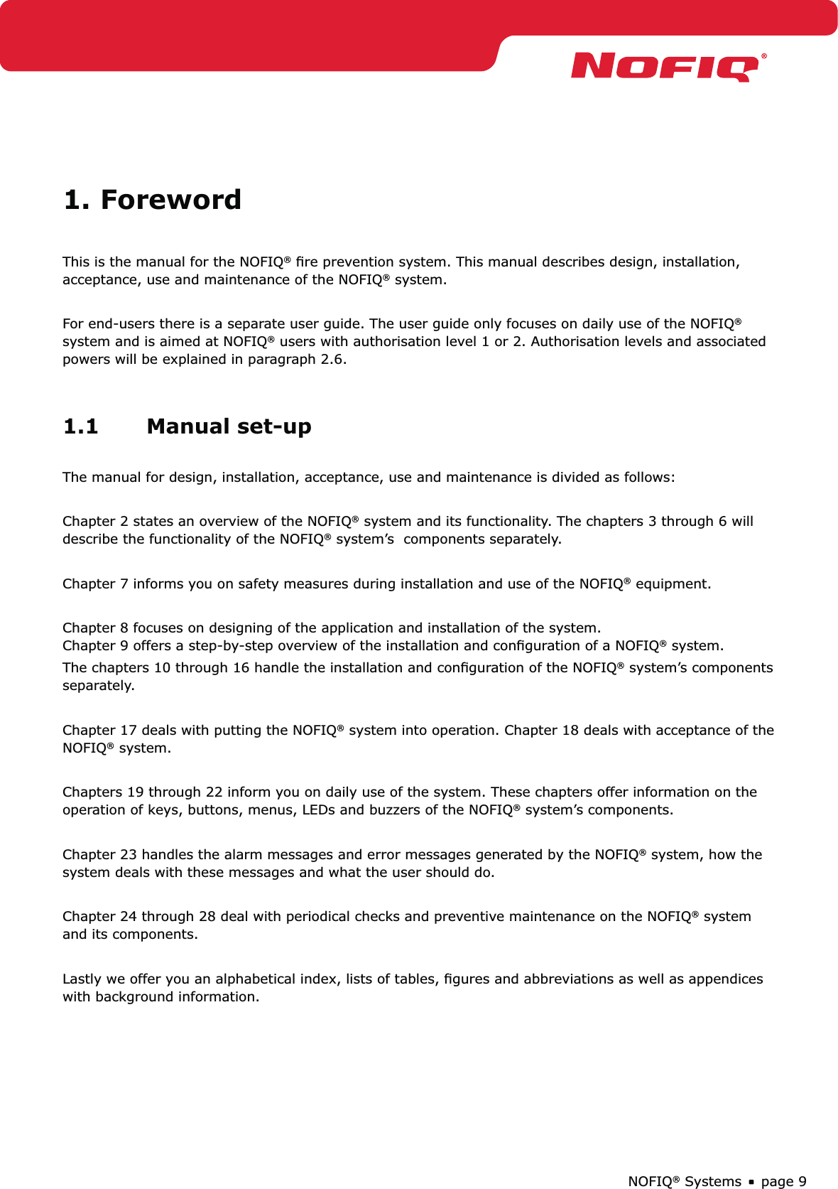


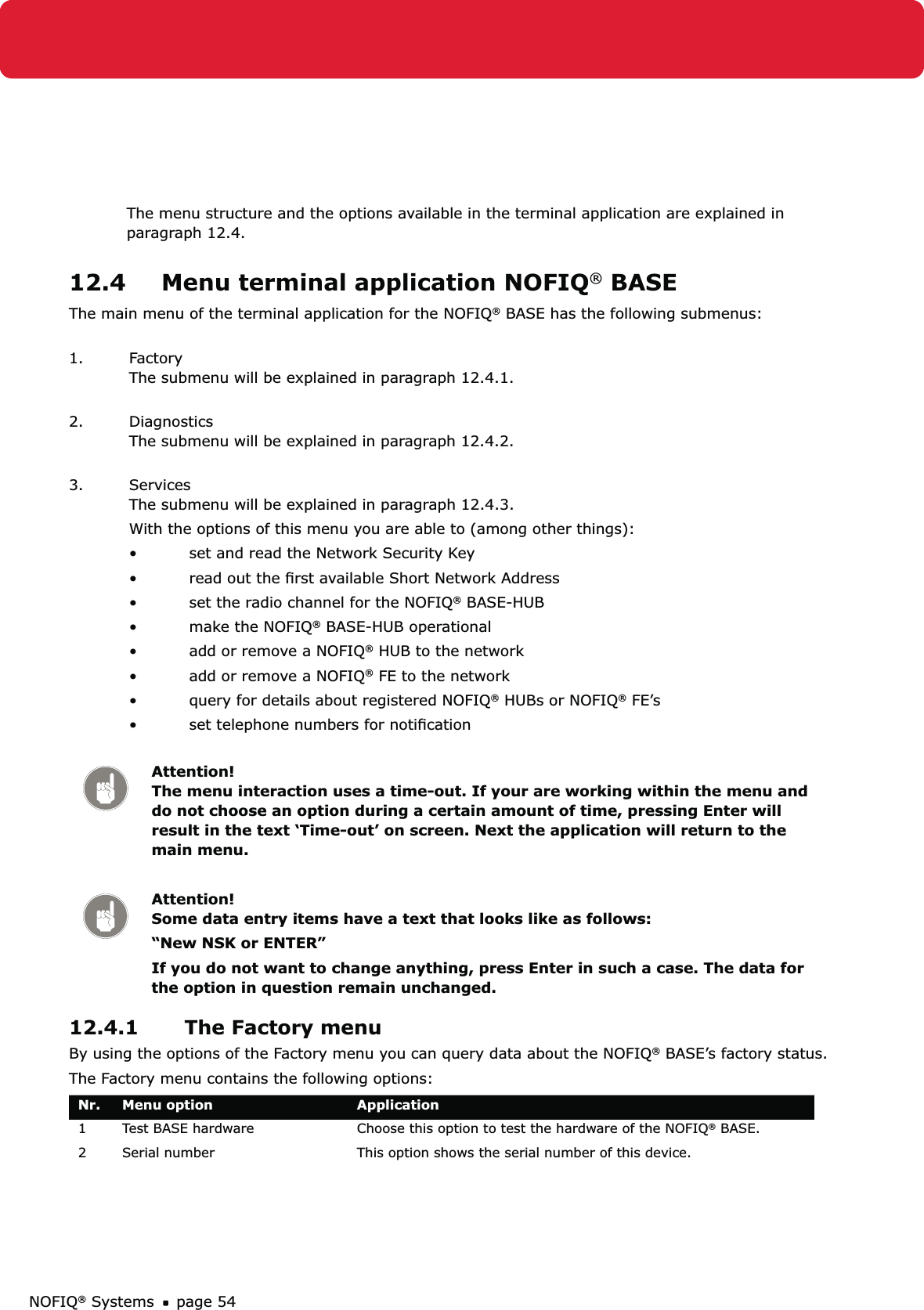
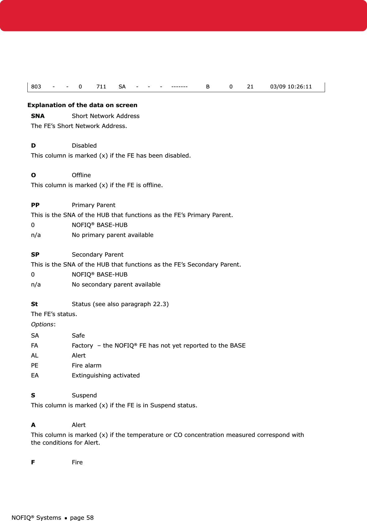
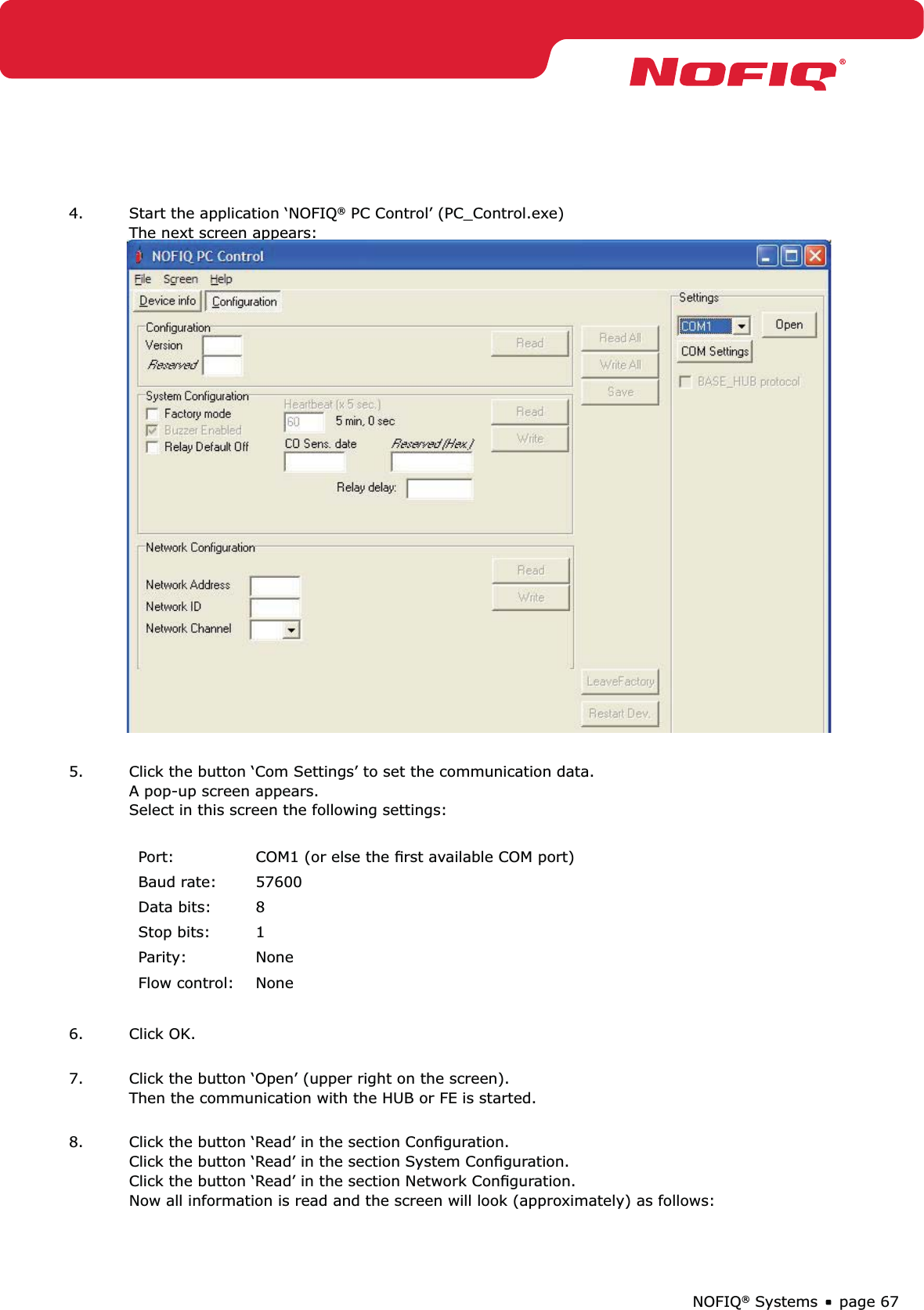
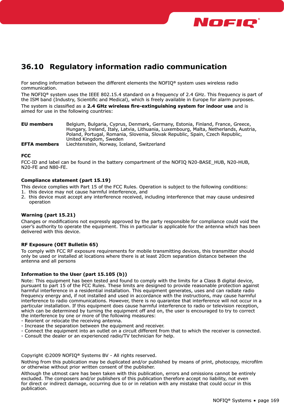
![NOFIQ® Systems page 689. You are now able to configure the HUB or FE. For a standalone FE the field ‘Standalone’ is ticked by default. In this case the fields ‘Network Address’, Network ID, Network Channel and Encryption Key do not apply. If you want to configure an FE for a network, you need to fill in at least the following fields:Network Address• This is the HUB’s or FE’s Short Network Address (SNA); a number in the range [2..65534].Network ID• This is the network’s identification number; a number in the range [1..255]. This number must be identical for each device in the network. Network Channel• This is the network’s radio channel; a number in the range [11..26]. This number must be identical for each device in the network.Encryption Key • (Hex)This the system’s Network Security Key (NSK); a number of 32 digits (32*[0..9]). Attention! The data mentioned above are mandatory for an FE in a NOFIQ network. Other data for a HUB or FE are set by default. If required you can change the other data in the section System Configuration. The meaning of all buttons and fields of this screen are explained in the next paragraphs.](https://usermanual.wiki/NOFIQ-Fire-and-Safety-Systems/102040A/User-Guide-1091726-Page-68.png)
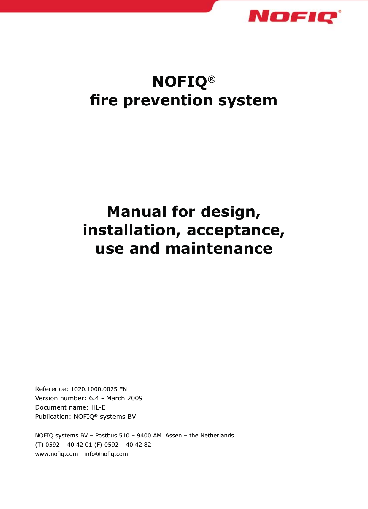
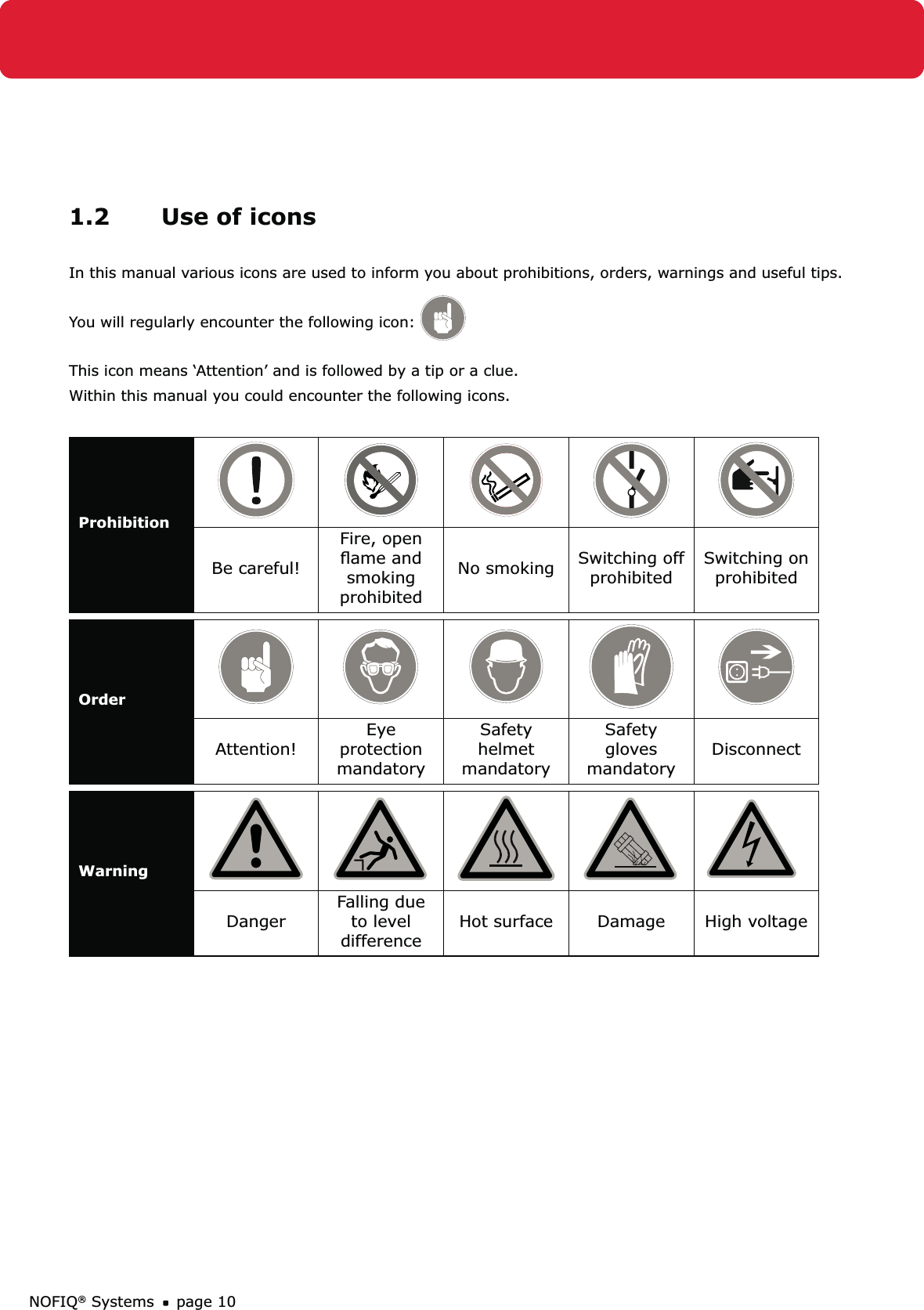
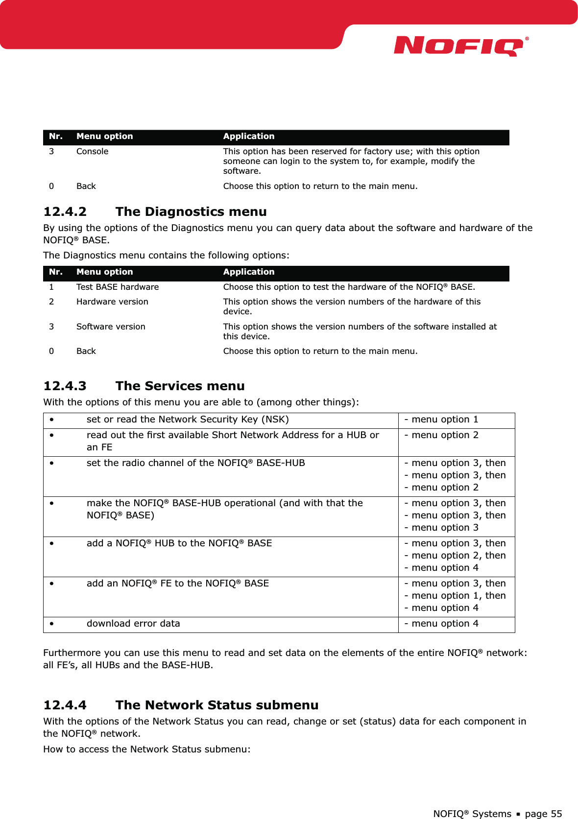
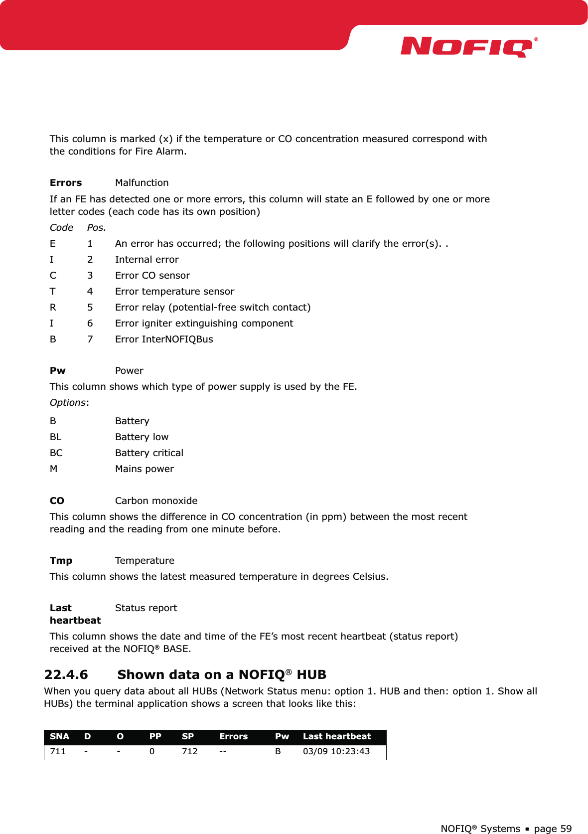
![NOFIQ® Systems page 70ReservedSoftware data. These are of no concern for the user.Trigger relay atHere you can choose in which situation the FE’s potential-free contact must be switched. You can choose from:• Alert • Pre-extinguishing (Fire alarm)• Error (Malfunction)Relay delayThe delay time (in seconds) before the potential-free contact will be switched.The maximum number of seconds that can be set is 120.ReadClick this button to read the configuration data of the HUB or FE.WriteClick this button to write the (modified) data of an HUB or FE. Click the button ‘Save’ to actually save the data.14.3.3 Fields and buttons from screen section Network ConfigurationThe screen section Network Configuration offers information about network settings of a HUB or FE. These data can be modified.StandaloneThis field must be ticked if the FE is to function standalone. If this field is ticked, the fields like ‘Network Address’, ‘Network ID’, ‘Network Channel’ and ‘Encryption Key’ will not be available.Network AddressThis the Short Network Address, the unique network address granted to the HUB or FE. Attention! The network address of the BASE-HUB is 0; this number can never be granted to a HUB or FE.Network IDThe is a unique identification number of the entire NOFIQ® network; a number in the range [1..255]. This number must be identical for each device (HUB, FE and BASE-HUB) in the network. Thanks to this ID different networks are separated from each other and FE data cannot turn up in another network (e.g. the neighbour’s network) by accident.](https://usermanual.wiki/NOFIQ-Fire-and-Safety-Systems/102040A/User-Guide-1091726-Page-70.png)
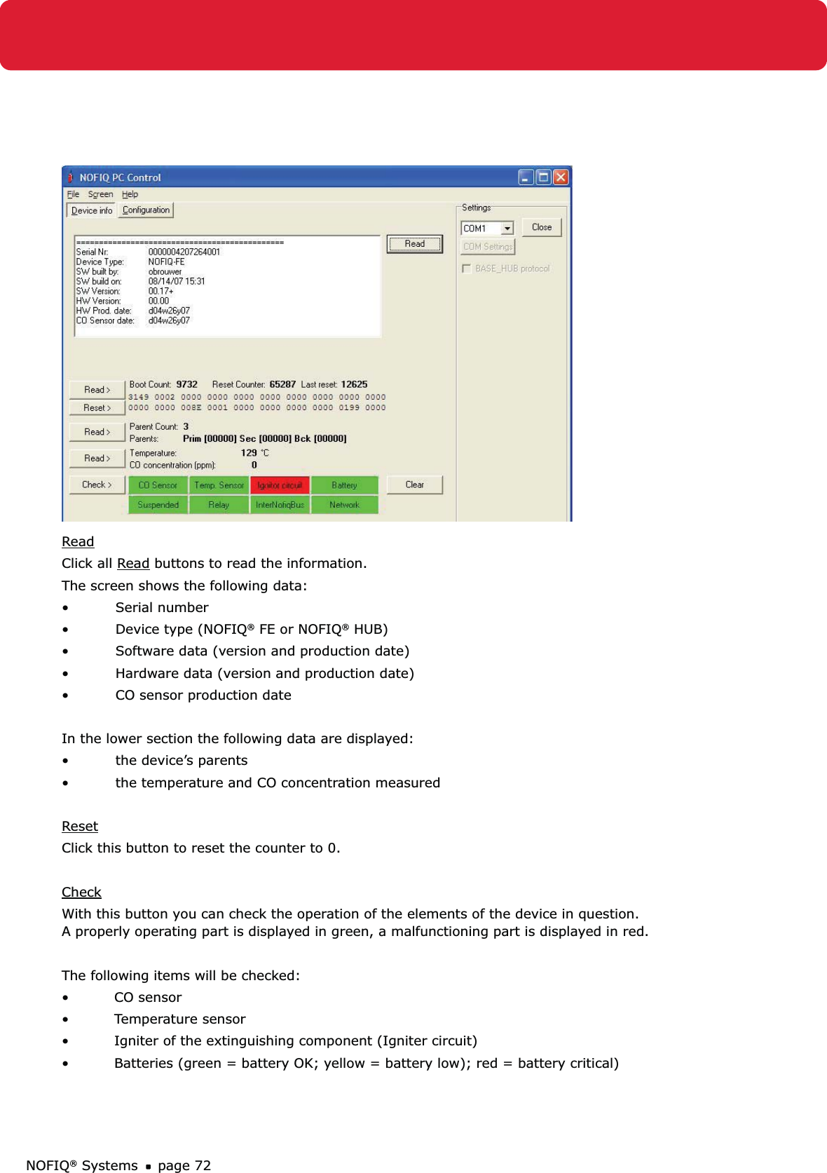
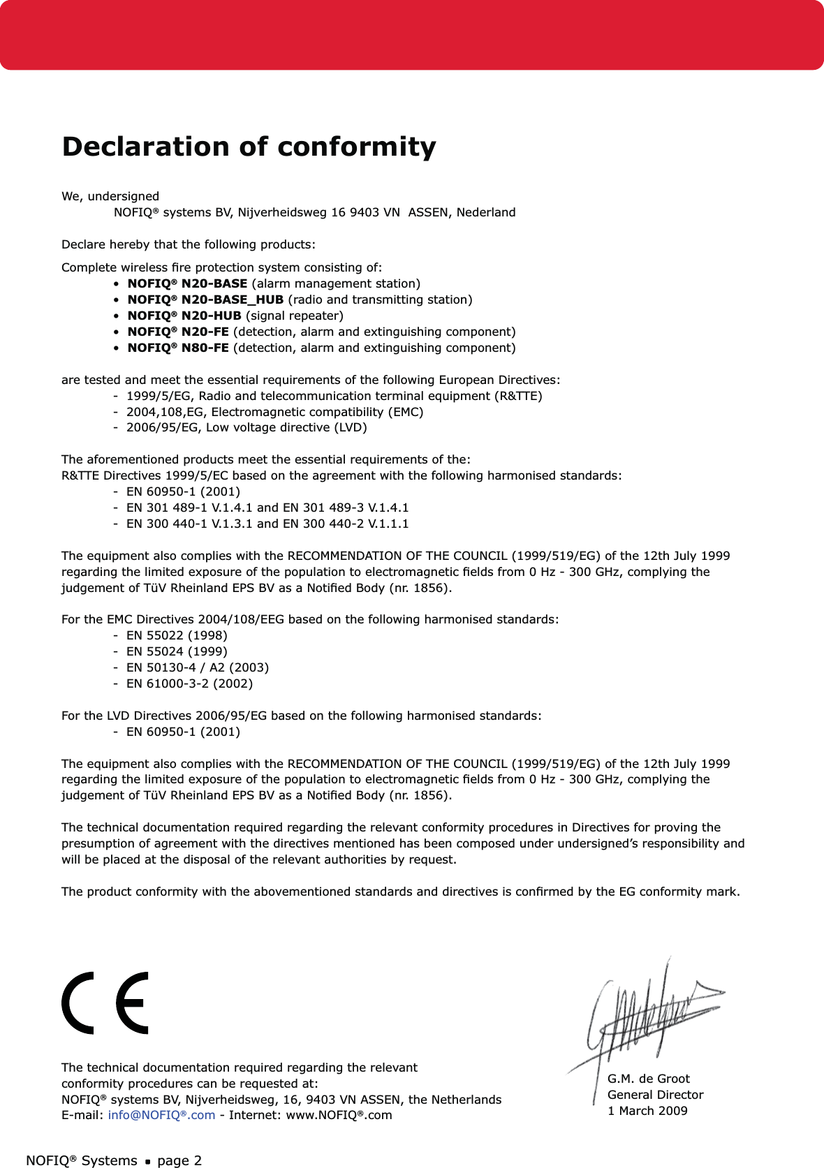
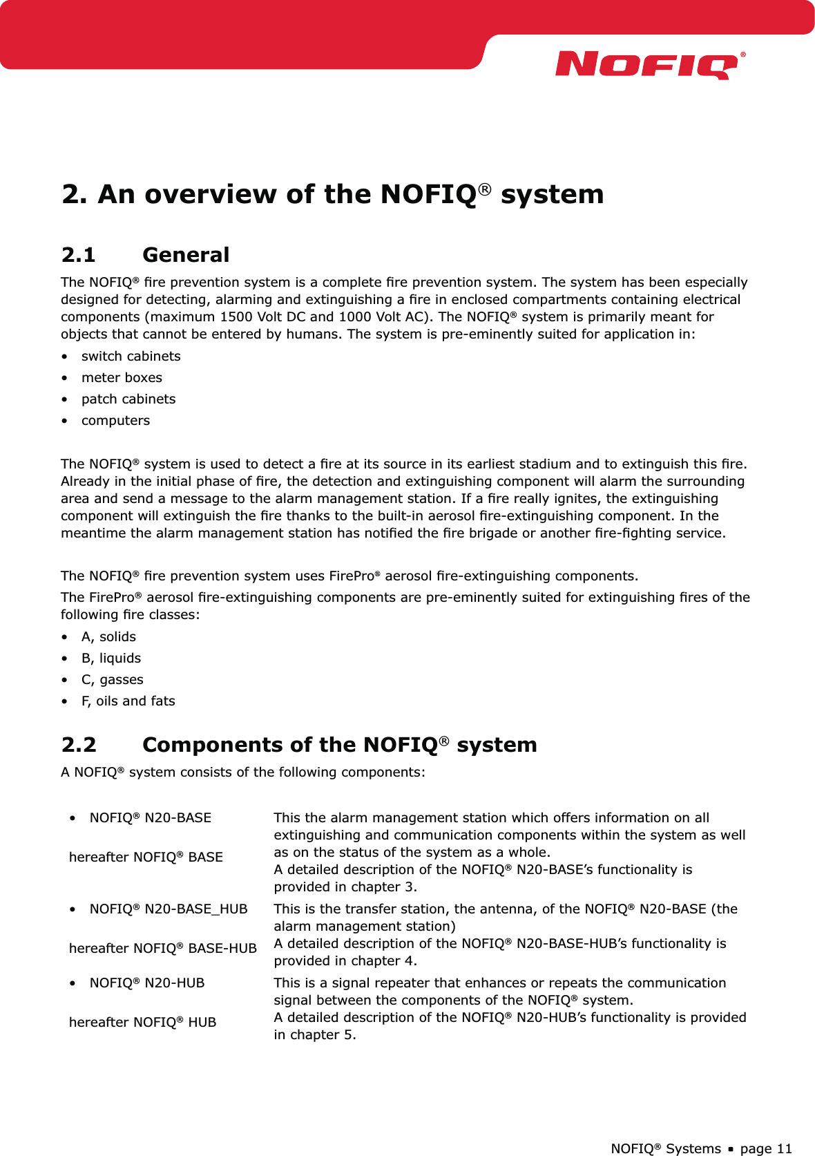
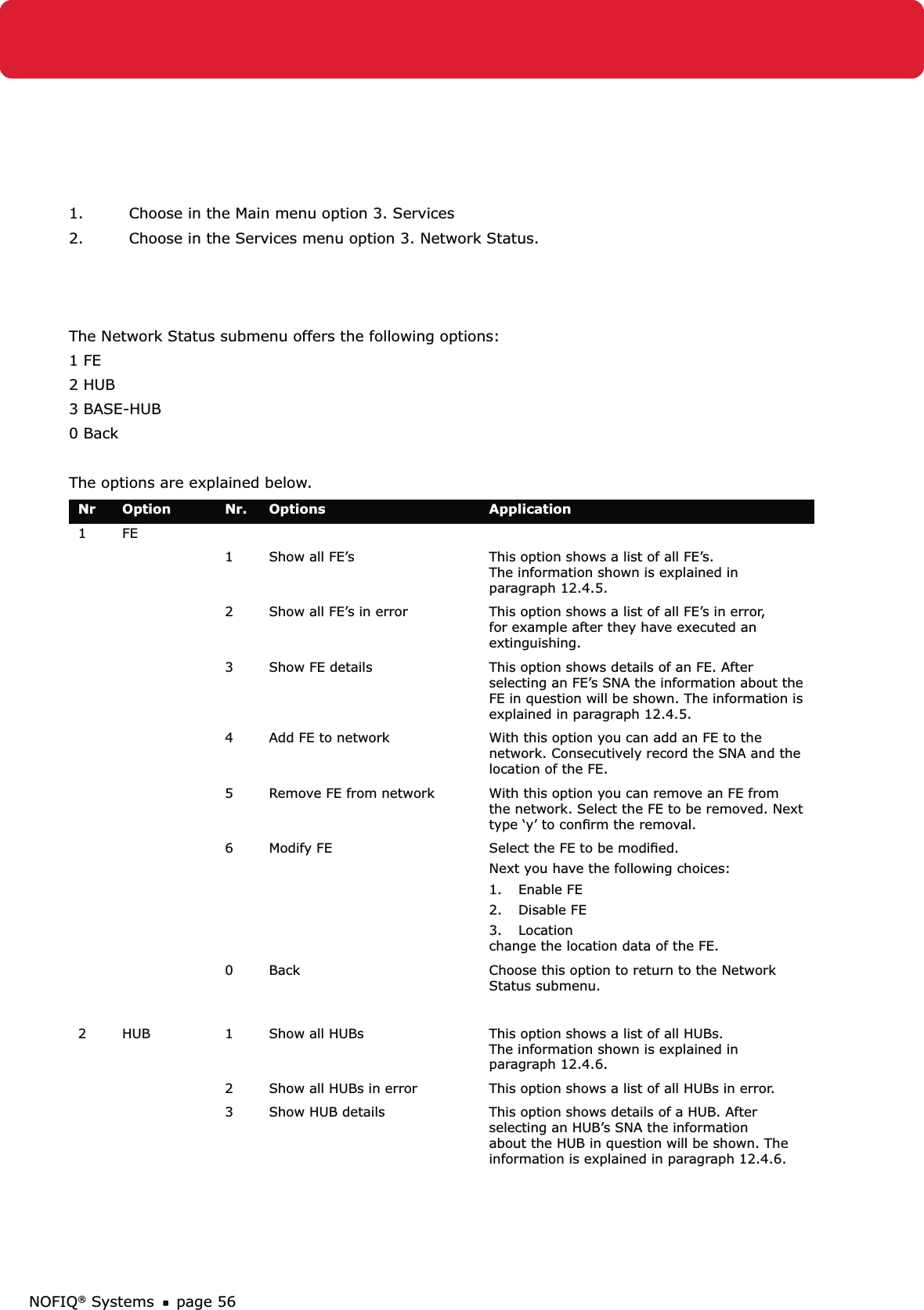
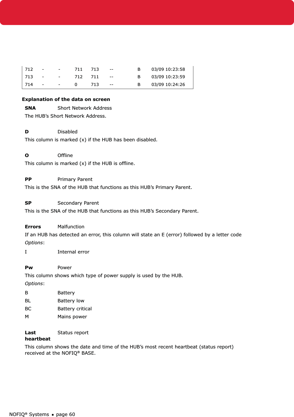
![page 71NOFIQ® SystemsNetwork ChannelThis the network’s radio channel; a number in the range [11..26]. This number must be identical for all devices in the network.Encryption Key (Hex)This the Network Security Key (NSK), a code that prevents interception of NOFIQ® network communication by external devices. The NSK s a number of 32 digits (32 * [0..9]).This code must be identical for each device in the network.ReadClick this button to read the network data of the HUB or FE.WriteClick this button to write the (modified) network data of an HUB or FE. Click the button ‘Save’ to actually save the data.14.3.4 Other buttons from screen section ConfigurationRead AllClick this button to read all data of the HUB or FE.Write AllClick this button to write all (modified) data of an HUB or FE. Click the button ‘Save’ to actually save the data.SaveClick this button to save data.Leave FactoryClick this button to have the HUB or FE leave factory status.Restart Dev.Click this button to restart a FE, HUB or BASE-HUB.Device Info Click this button to retrieve device information on the FE of HUB. Next a screen appears; this screen’s data and buttons will be explained in paragraph 14.3.5.14.3.5 Buttons and data on the screen Device infoClicking the Device Info button gathers information about the NOFIQ® FE or NOFIQ® HUB. If you click this button, the following screen appears:](https://usermanual.wiki/NOFIQ-Fire-and-Safety-Systems/102040A/User-Guide-1091726-Page-71.png)