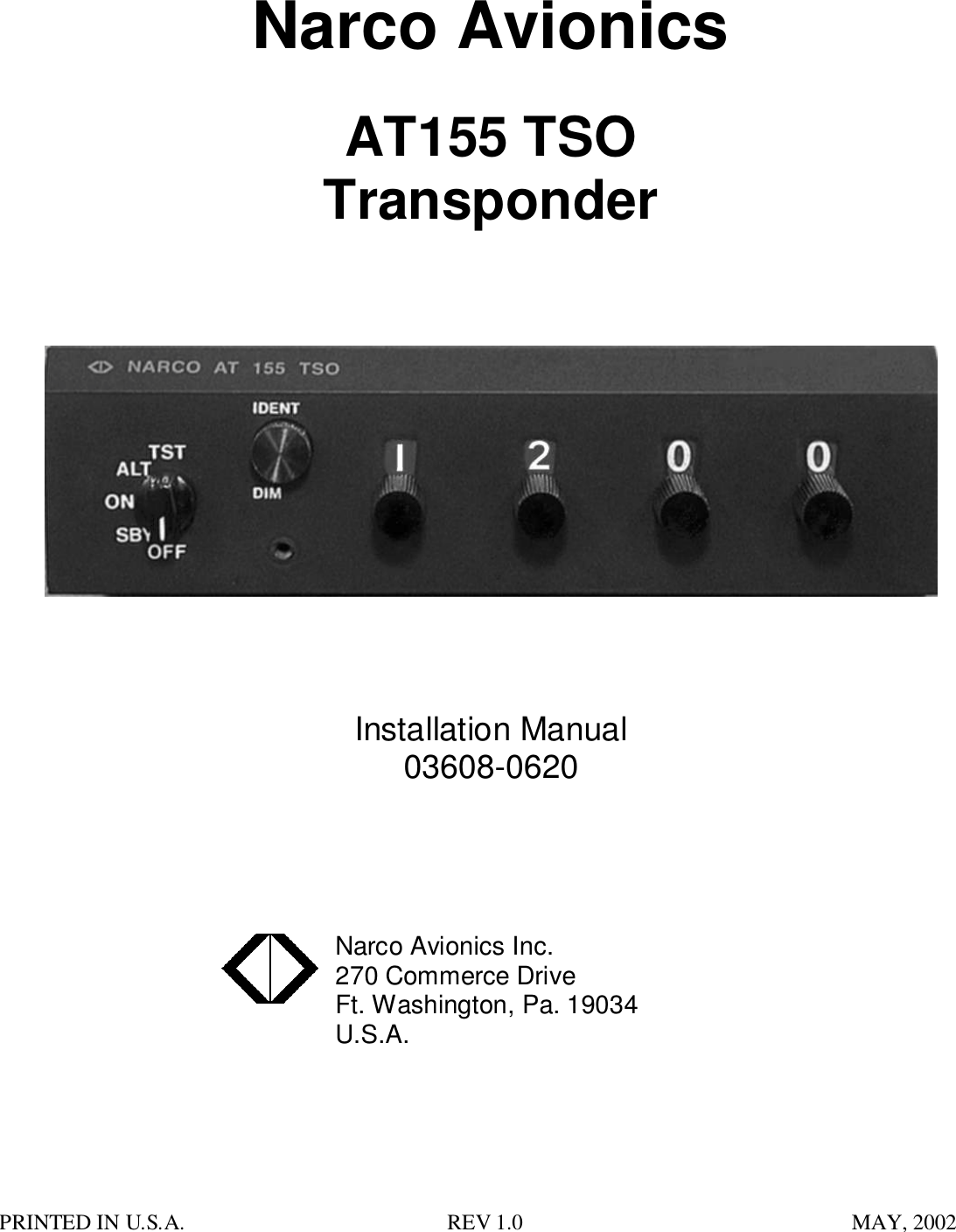
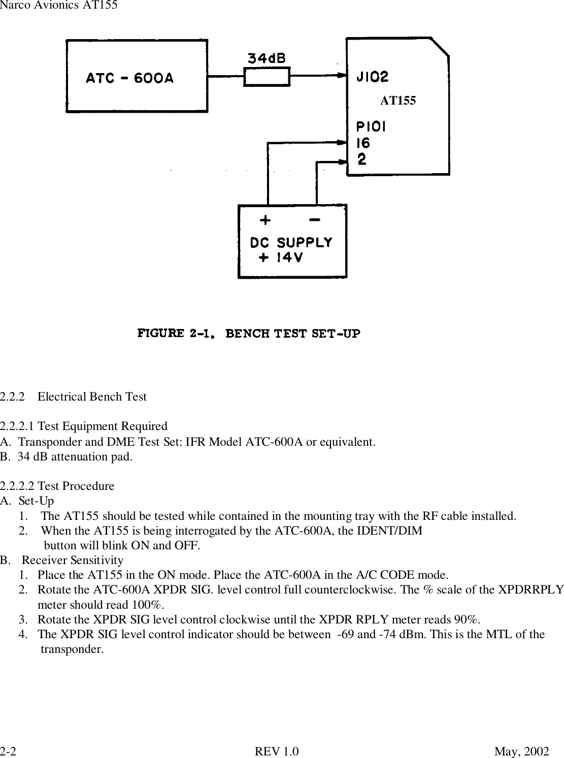
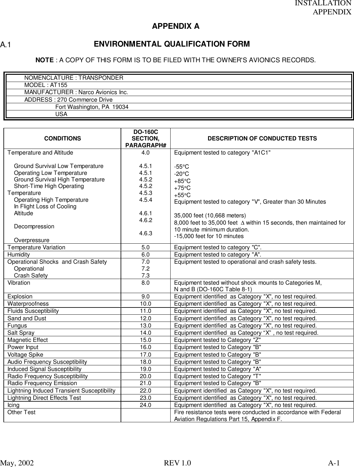
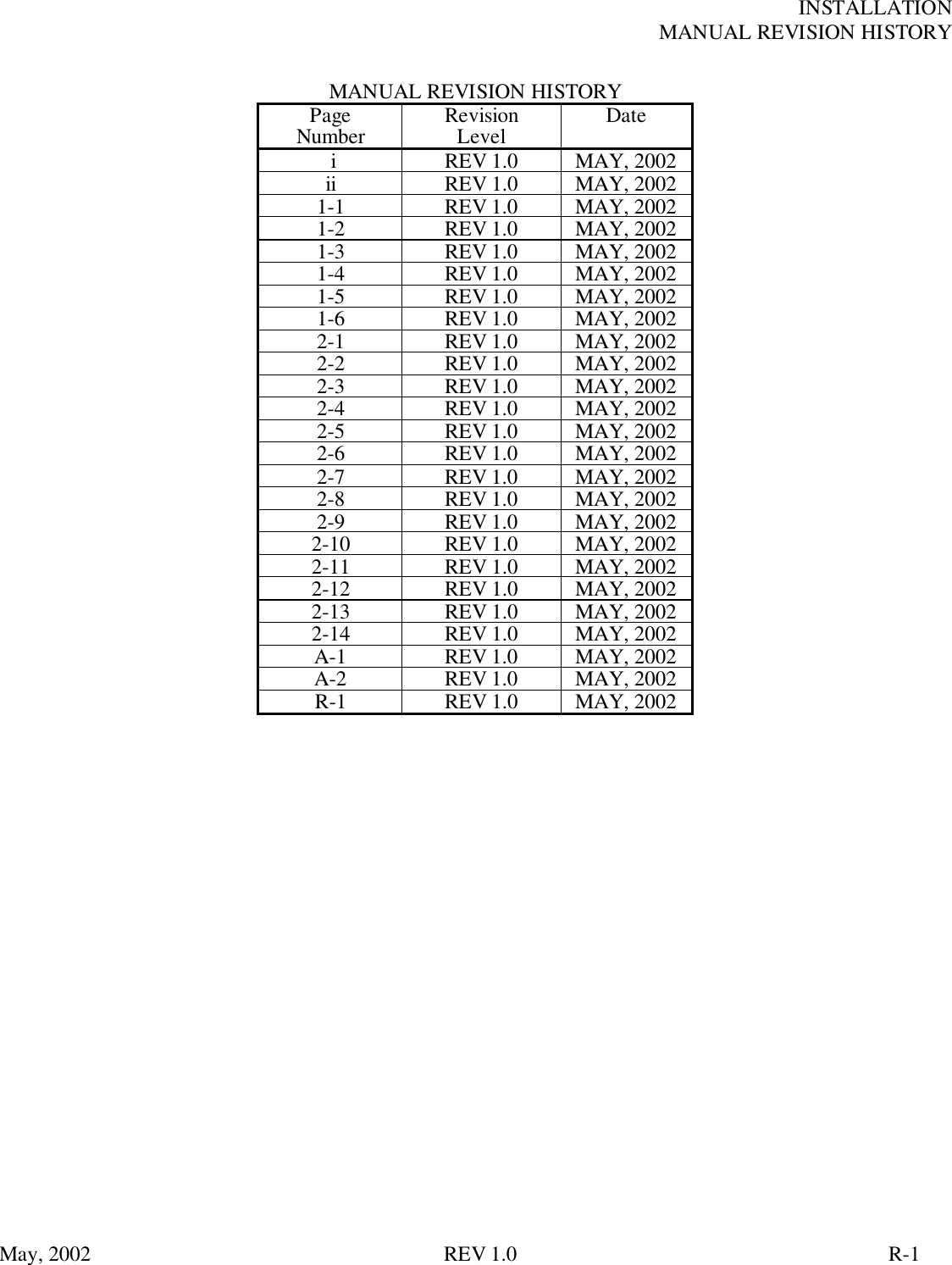
Narco Avionics AT155 Aviation Transponder User Manual installation manaul
Narco Avionics Inc Aviation Transponder installation manaul
UserManual.wiki
>
Narco Avionics
>
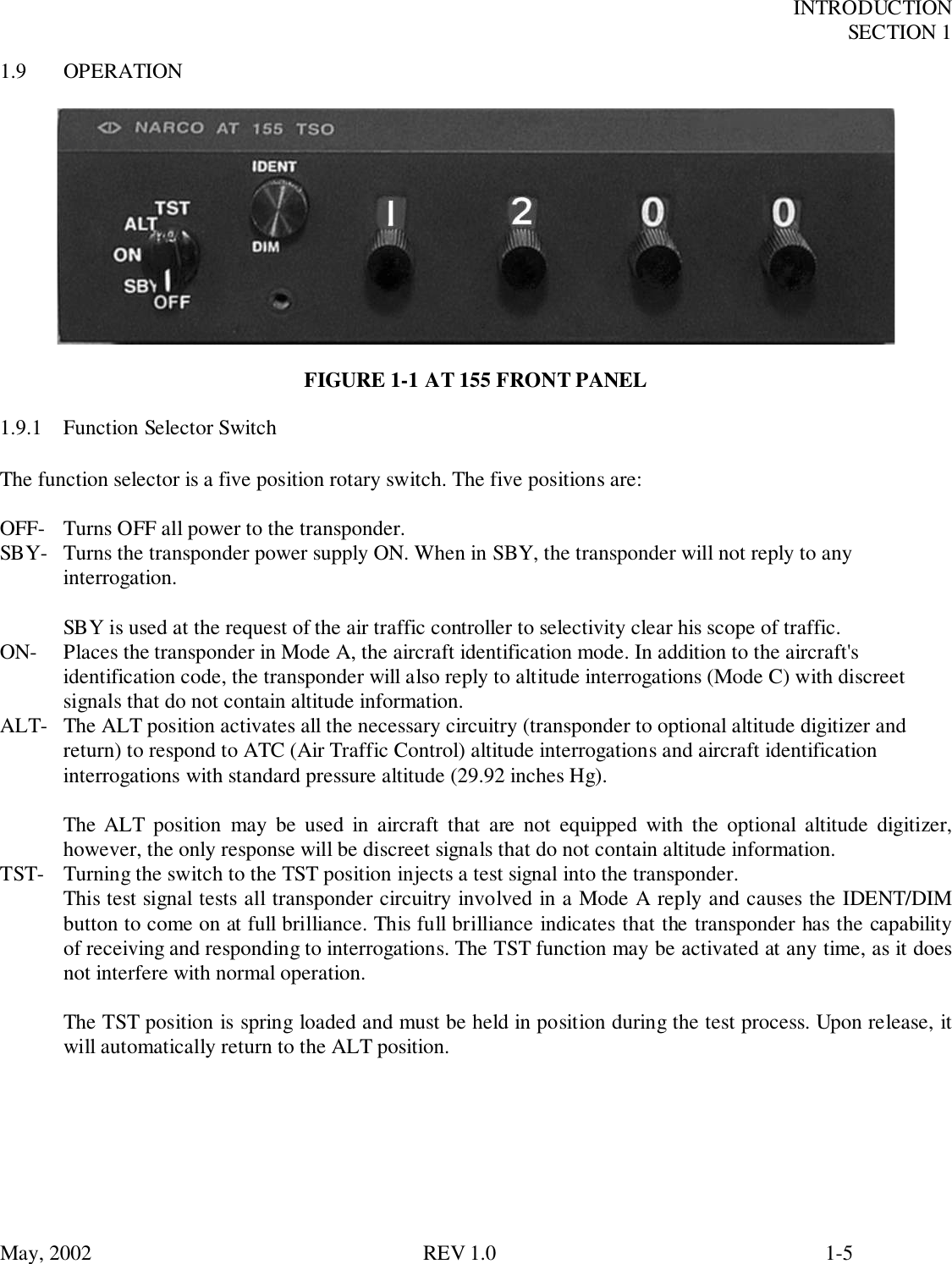
AT155 User Manual
installation manaul
Navigation menu
Upload a User Manual
Namespaces
Wiki Guide
HTML
PDF
Info
Views
User Manual
Discussion / Help
Navigation