Nortech PD230TD236 Vehicle Detector User Manual 302UM0017 01a PD230 Enh NewHousing NoApprovalsPage
Nortech International (PTY) LTD Vehicle Detector 302UM0017 01a PD230 Enh NewHousing NoApprovalsPage
UserManual.wiki
>
Nortech
>
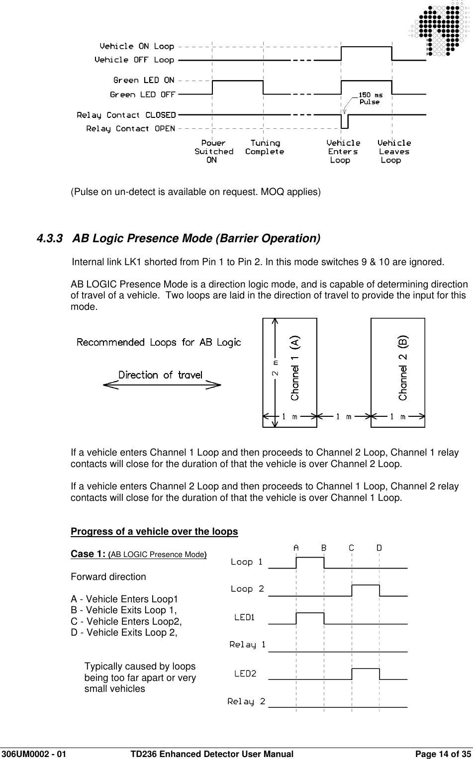
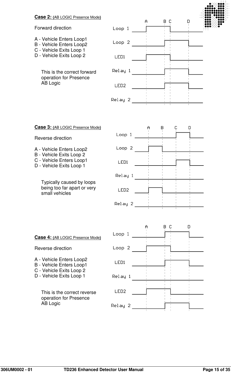
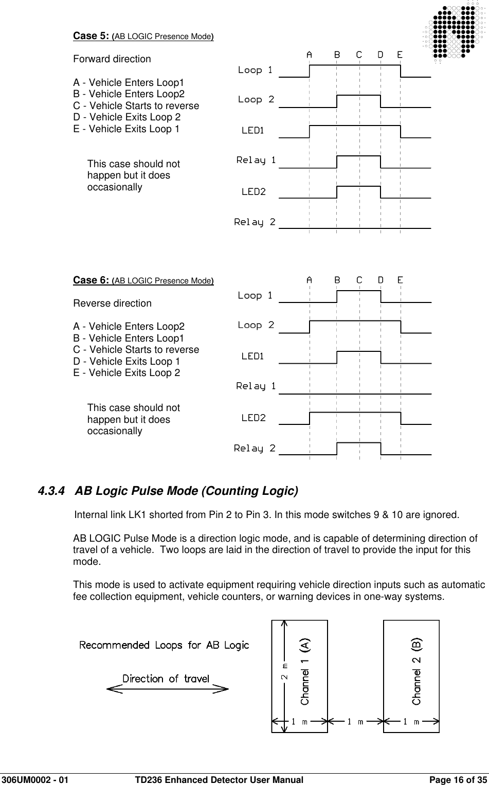
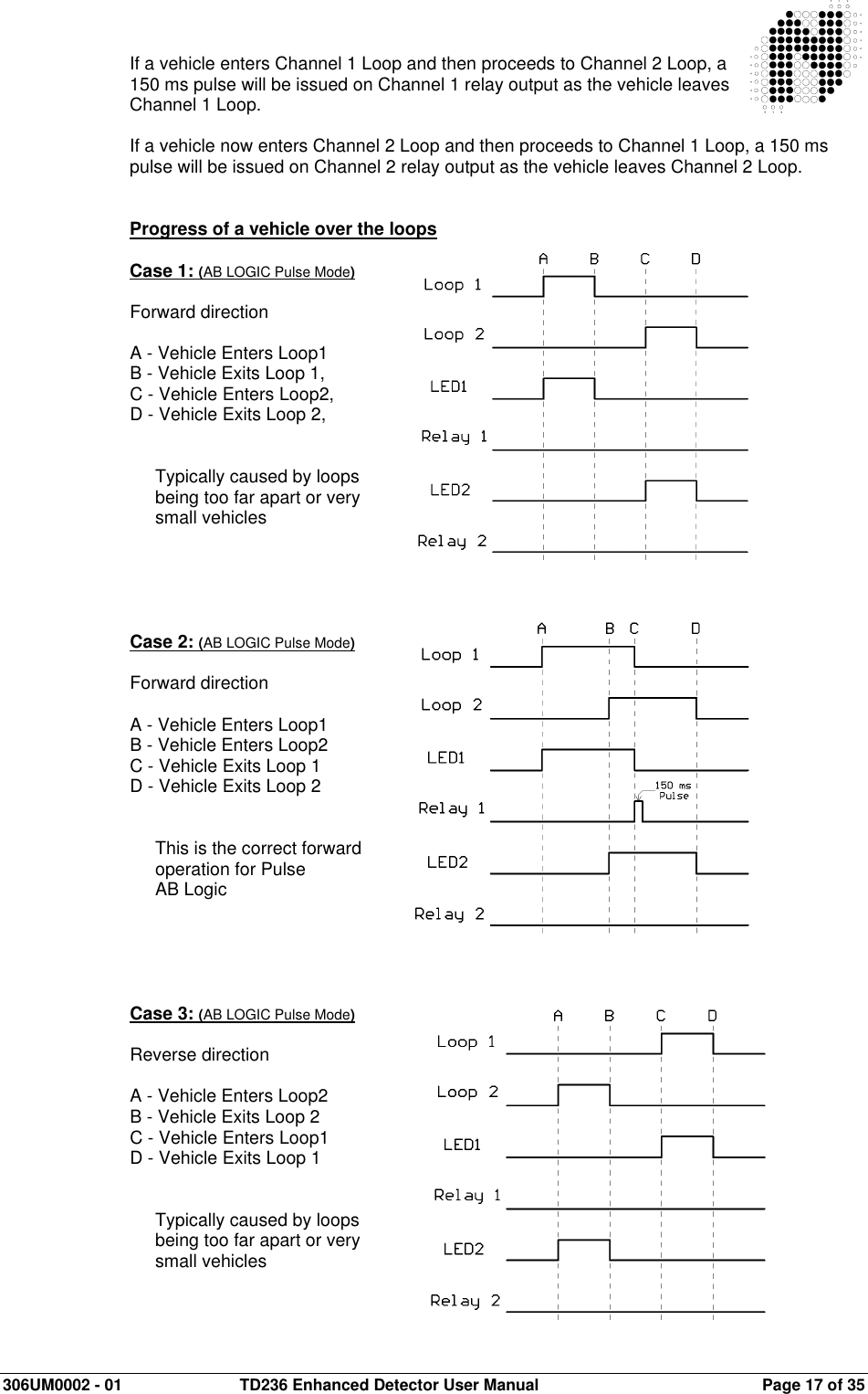
PD230TD236 User Manual
User Manual
Navigation menu
Upload a User Manual
Namespaces
Wiki Guide
HTML
PDF
Info
Views
User Manual
Discussion / Help
Navigation