Novatel 01017829 GPS Receiver with Bluetooth User Manual Technical Writer
Novatel Inc GPS Receiver with Bluetooth Technical Writer
UserManual.wiki
>
Novatel
>
01017829 User Manual
>
User Manual part 1
Contents
1.
User Manual part 1
2.
User Manual part 2
User Manual part 1
Navigation menu
Upload a User Manual
Namespaces
Wiki Guide
HTML
PDF
Info
Views
User Manual
Discussion / Help
Navigation


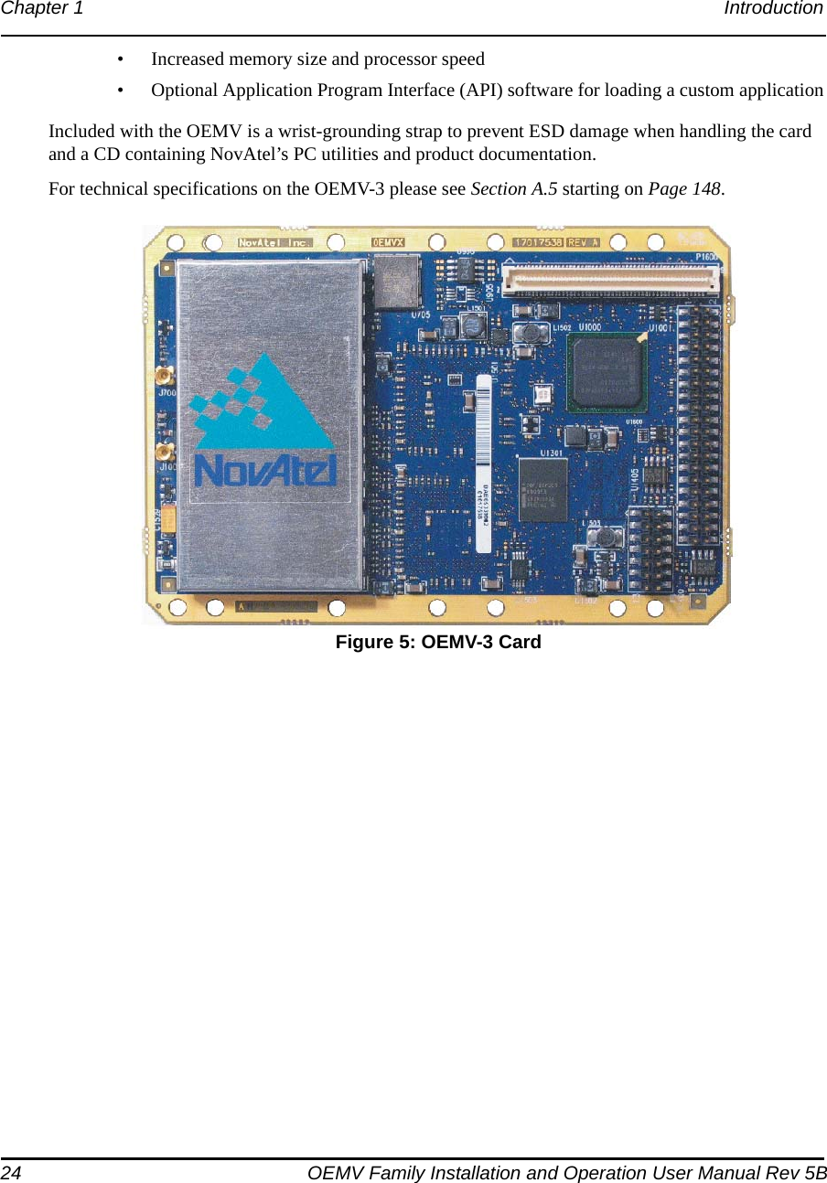

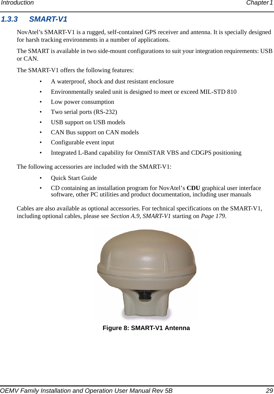
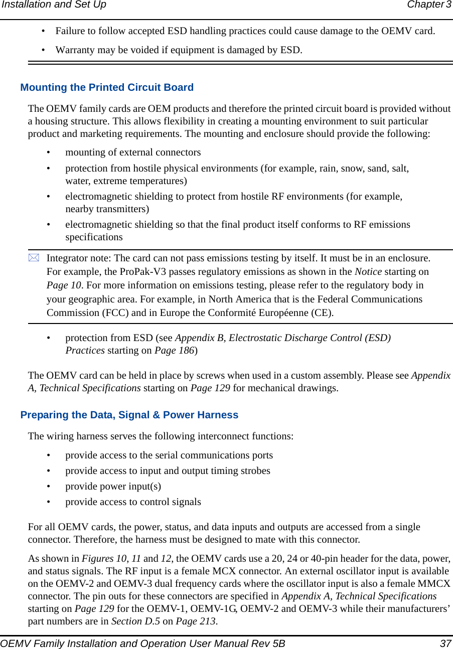
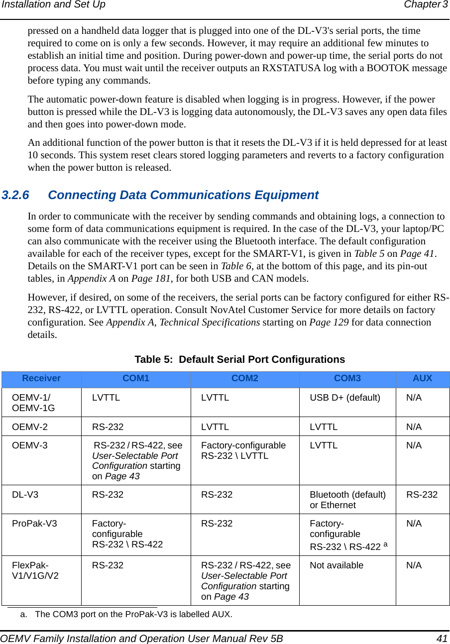
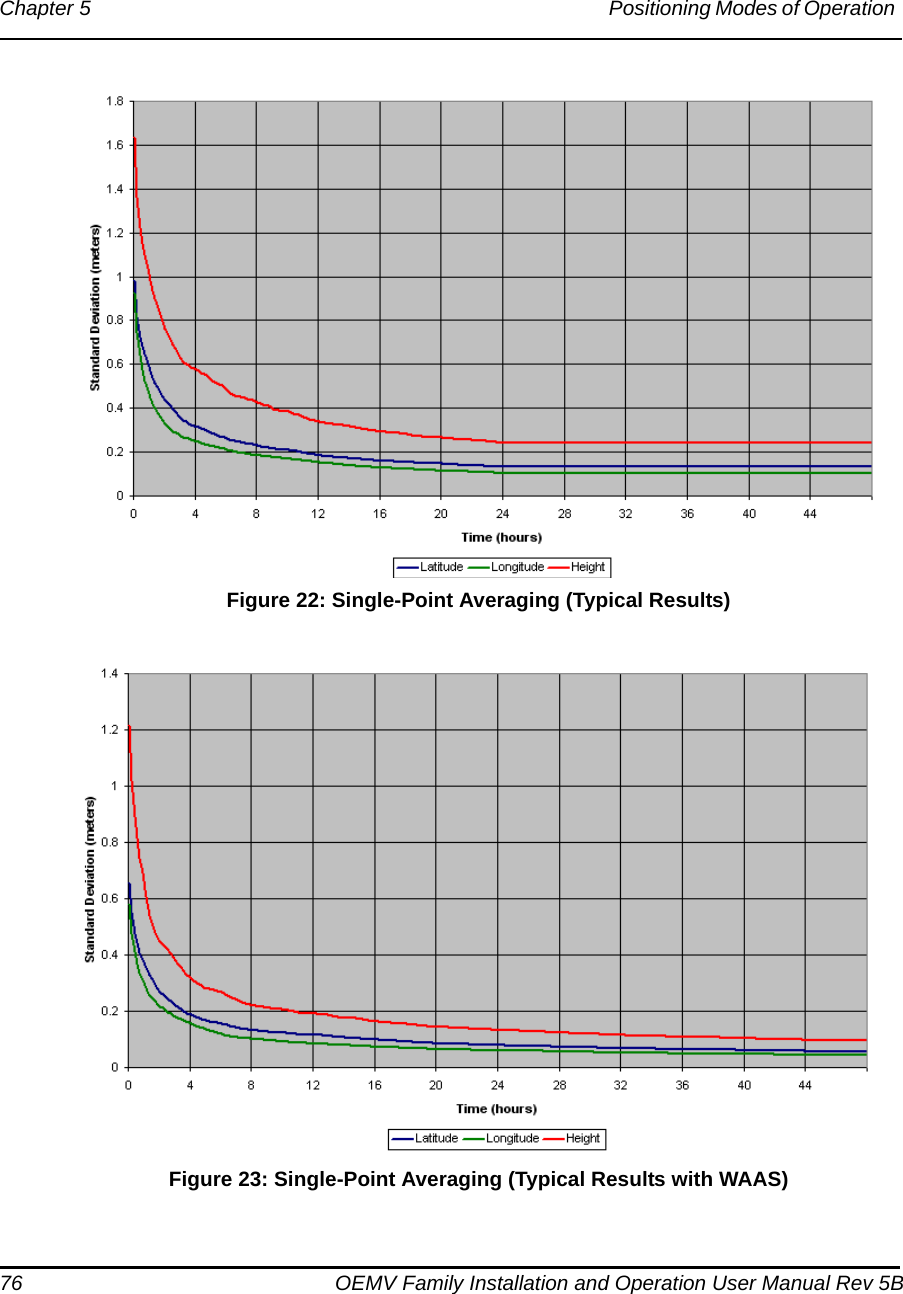
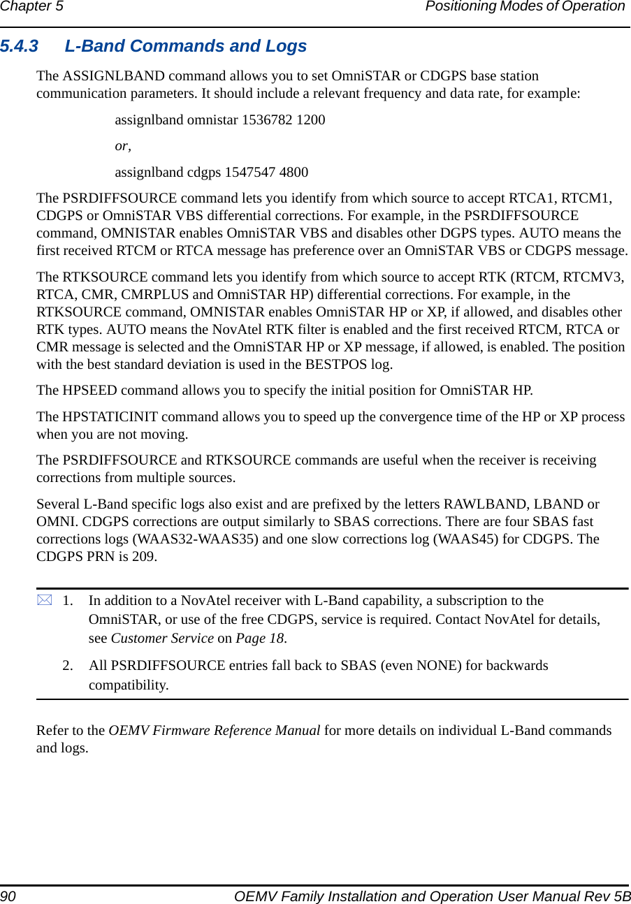
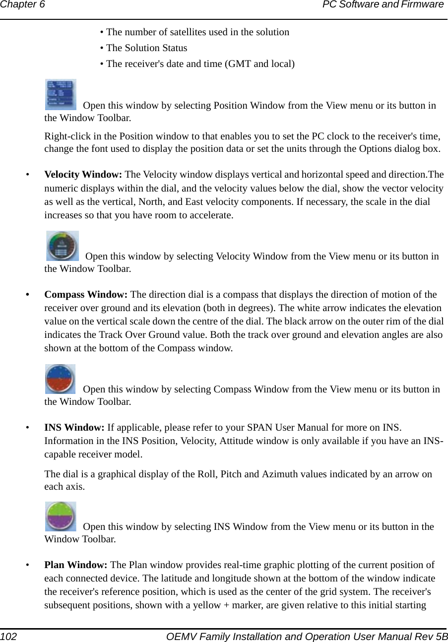
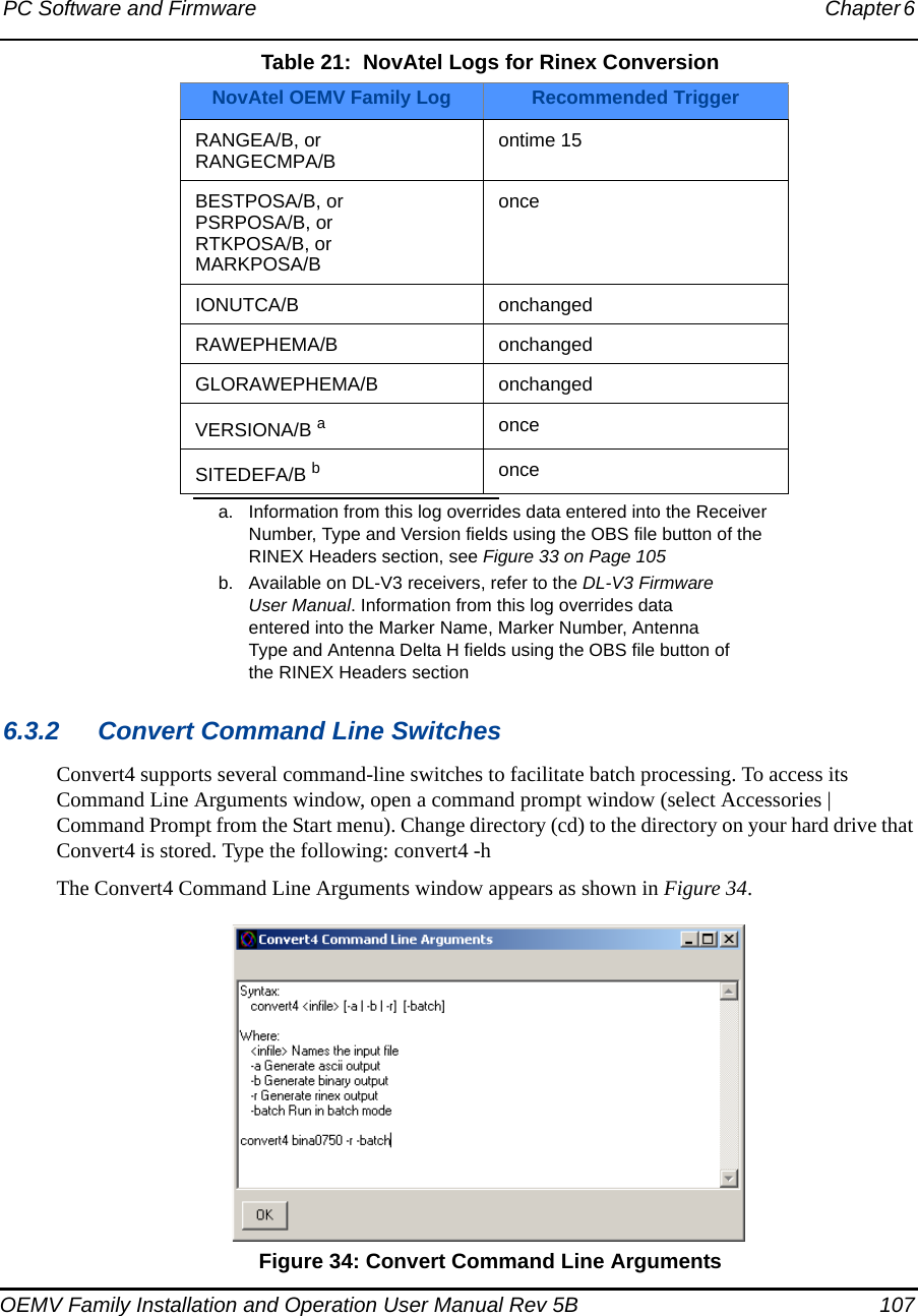
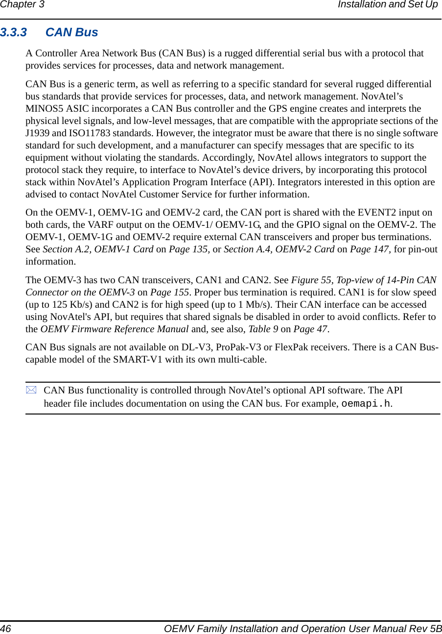
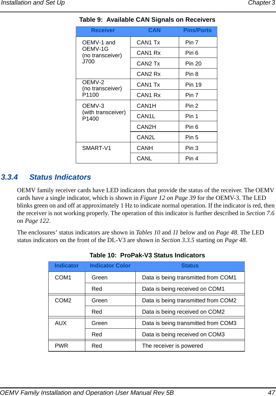
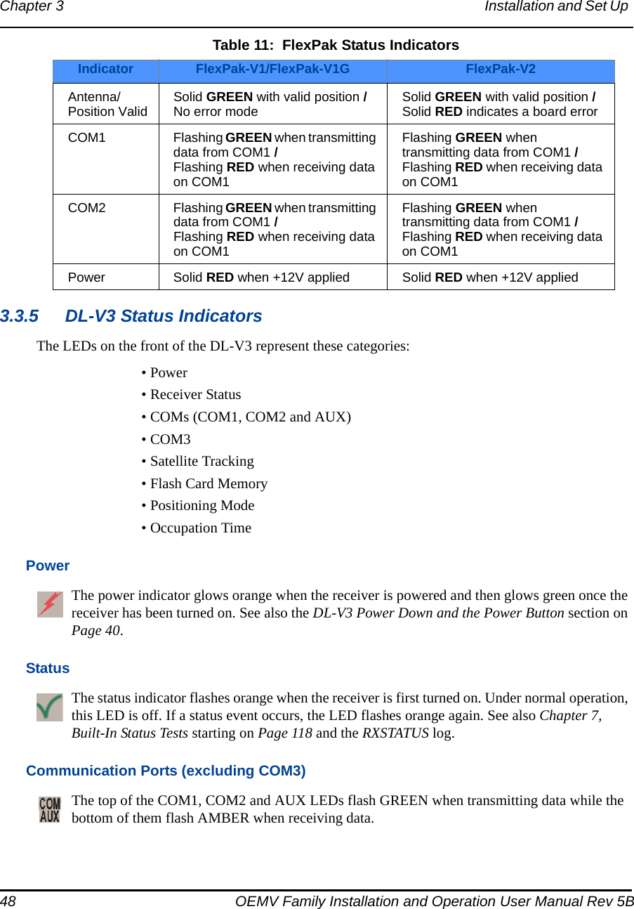
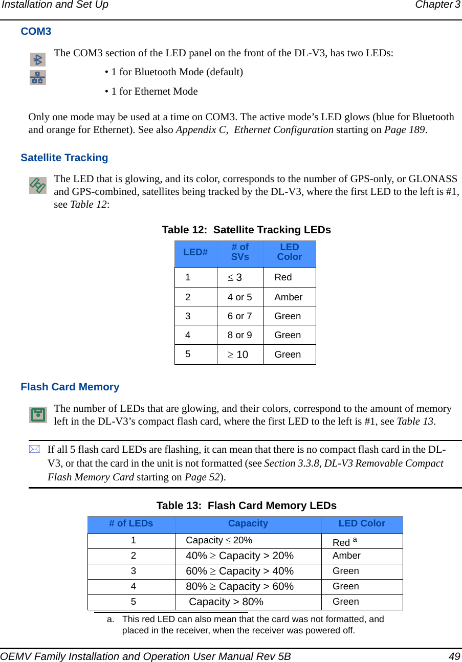
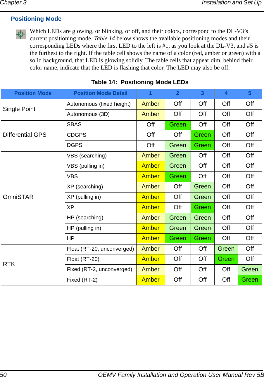
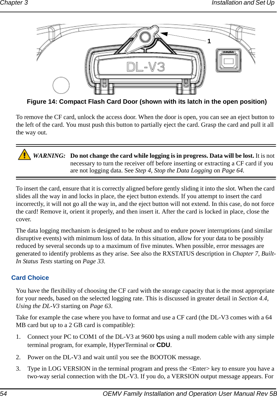
![44 OEMV Family Installation and Operation User Manual Rev 5BChapter 3 Installation and Set Up V3 COM3 Configuration starting on Page 44.The OEMV-3 offers a user-selectable configuration for the COM1 port. For OEMV-3, the configuration is selected using the USERIO1 pin. By default, RS-232 is selected as the USERIO1 input is set LOW by an internal pull-down resistor. To select RS-422 upon startup, apply 3.3 V to USERIO1. Alternatively, tie USERIO1 to pin 38 of the 40-pin connector on the OEMV-3.Pin 38, on the 40-pin connector, is usually an ERROR indicator, and during normal OEMV card operations is set LOW, but for < 2 s during OEMV card initialization, immediately after applying power to the OEMV card, this pin is set HIGH at 3.3 Volts. It drops to LOW <2 s later when the OEMV card has been fully booted up and the [COMx] prompt is output from the OEMV card on all COM ports.USERIO1 needs to be initialized HIGH during this initial boot-up phase in order to set up the COM1 port for RS-422 mode. Therefore, tie pin 38 to a 3.3 V source to trigger the USERIO1, to set the COM1 port to RS-422 mode.DL-V3 COM3 ConfigurationYou can switch between Ethernet and Bluetooth (default) on COM3 using the APPCONTROL command. In the case of switching to Ethernet, power is automatically applied to it after switching. Bluetooth, on the other hand, may be in sleep mode. If Bluetooth operation is required, it must be put into active mode using the COMVOUT command. The ethenet requires more setup configuration steps. These involve configuring serial, and network, parameters. See also Appendix C starting on Page 189 for details. Further details on the commands above can be found in the DL-V3 Firmware Reference Manual.3.3 Additional Features and InformationThis section contains information on the additional features of the OEMV family receivers, which may affect the overall design of your receiver system.3.3.1 StrobesOn OEMV family receivers, a set of inputs and outputs provide status and synchronization signals. These signals are referred to as strobes. Not all strobe signals are provided on all receivers. However, for those products for which strobes are available, you may want to design your installation to include support for these signals.Pin-out information can also be found in Appendix A:• OEMV-1 pin-out starting on Page 135• OEMV-1G pin-out starting on Page 141 • OEMV-2 pin-out starting on Page 147• OEMV-3 pin-out starting on Page 153• DL-V3 port pin-out on Page 158• ProPak-V3 port pin-out on Page 165](https://usermanual.wiki/Novatel/01017829.User-Manual-part-1/User-Guide-777993-Page-44.png)
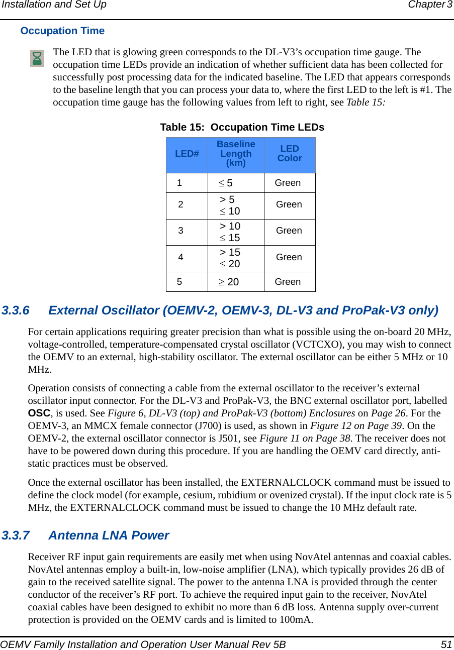
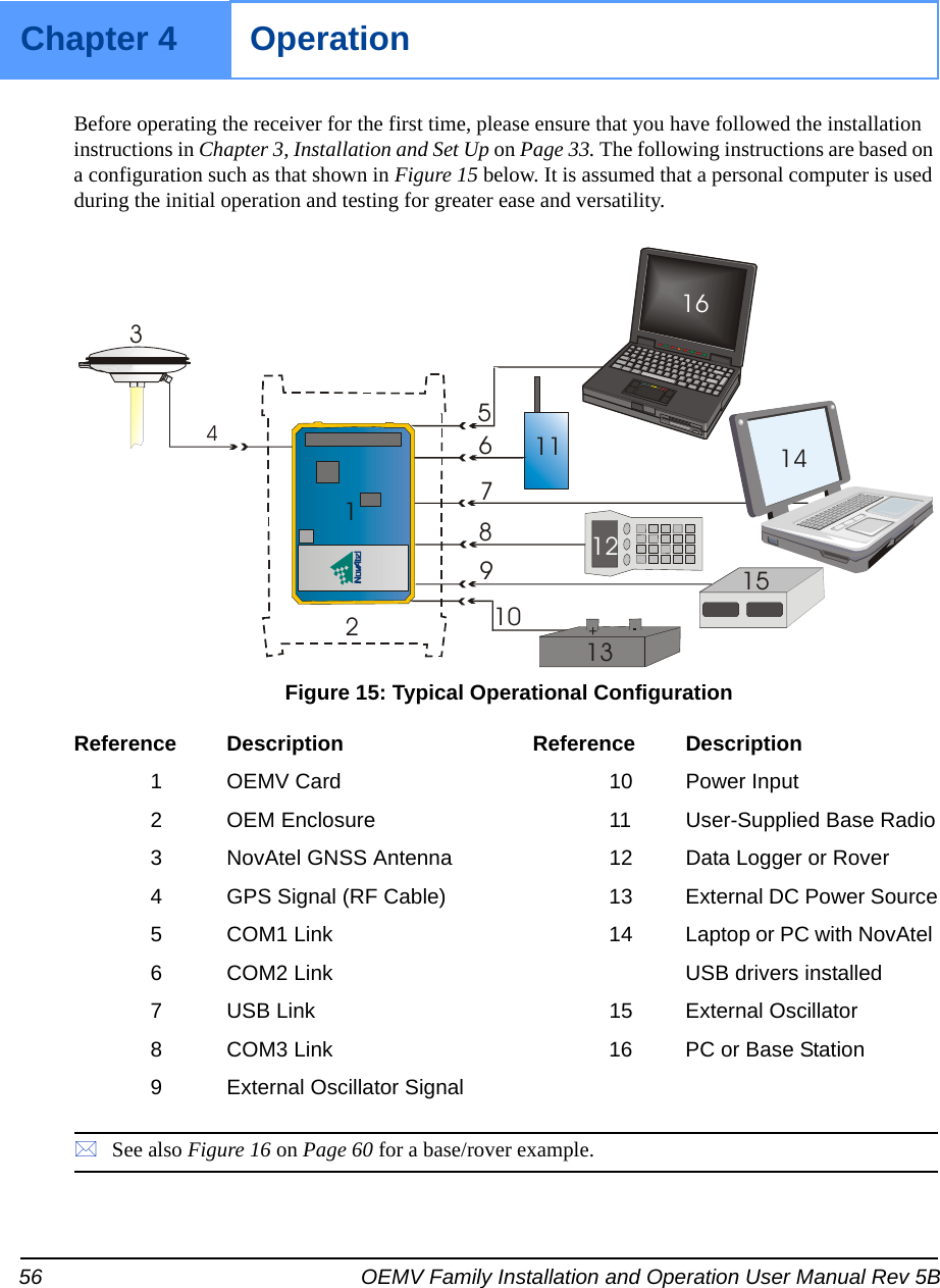
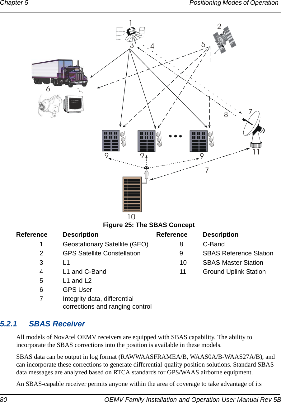
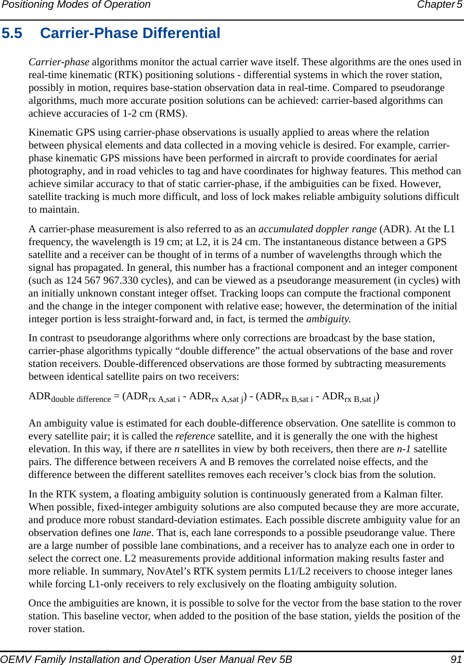
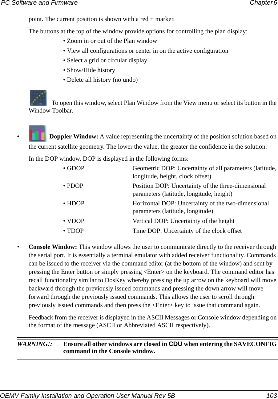
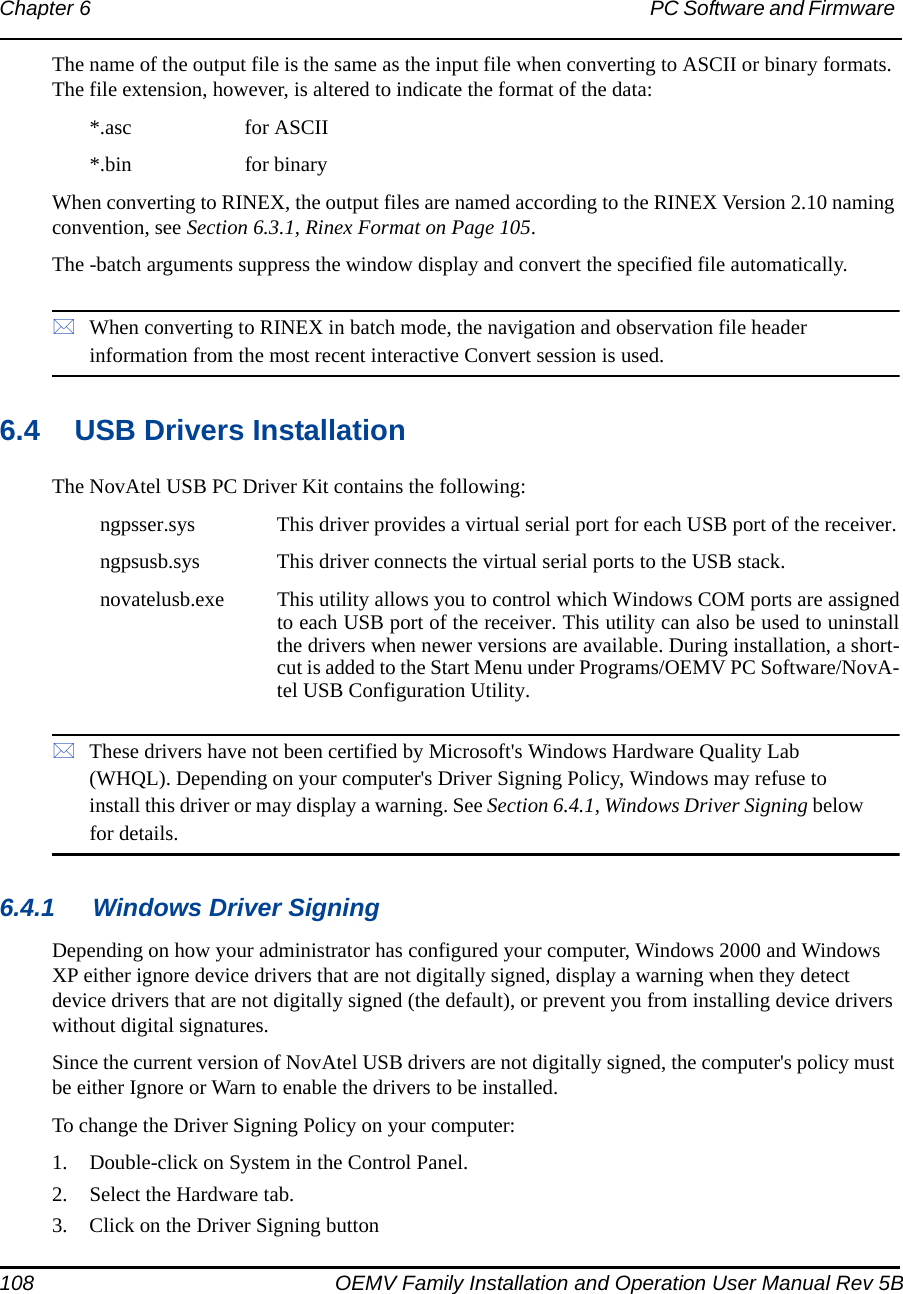
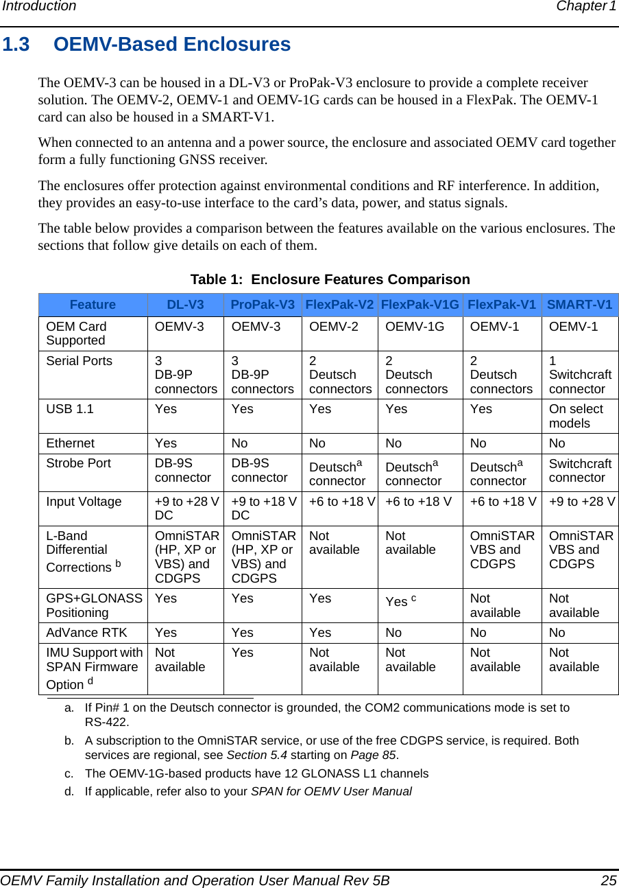
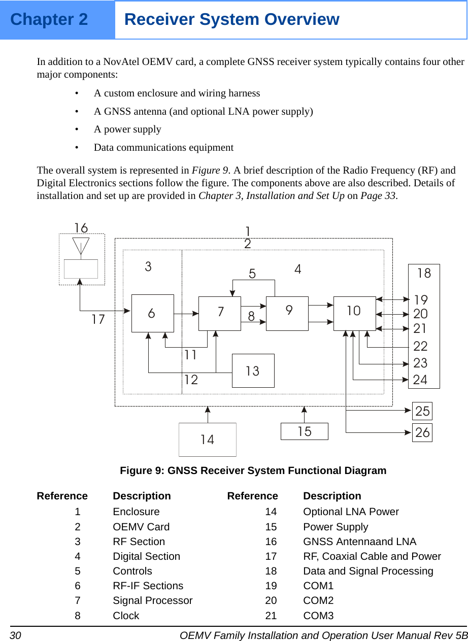
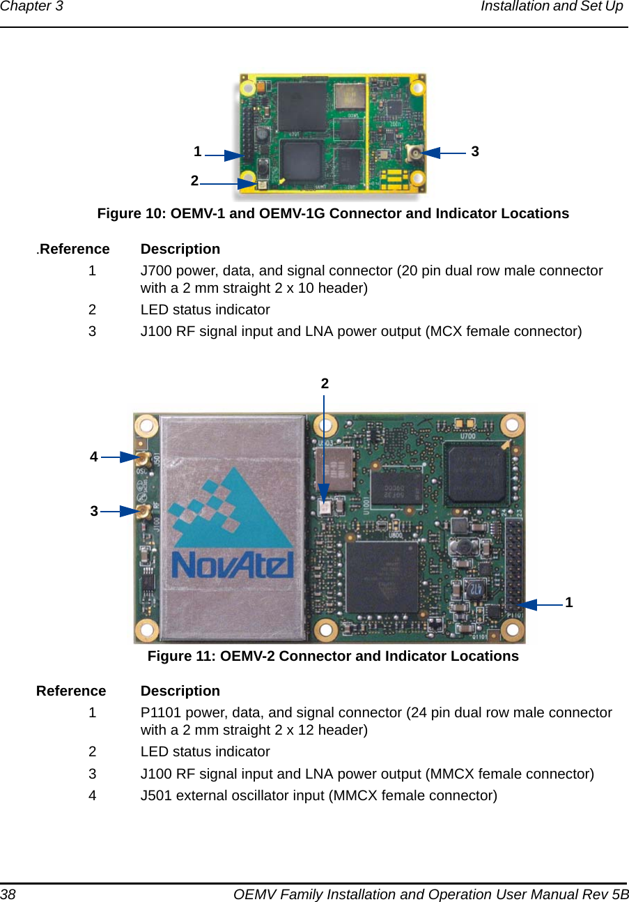
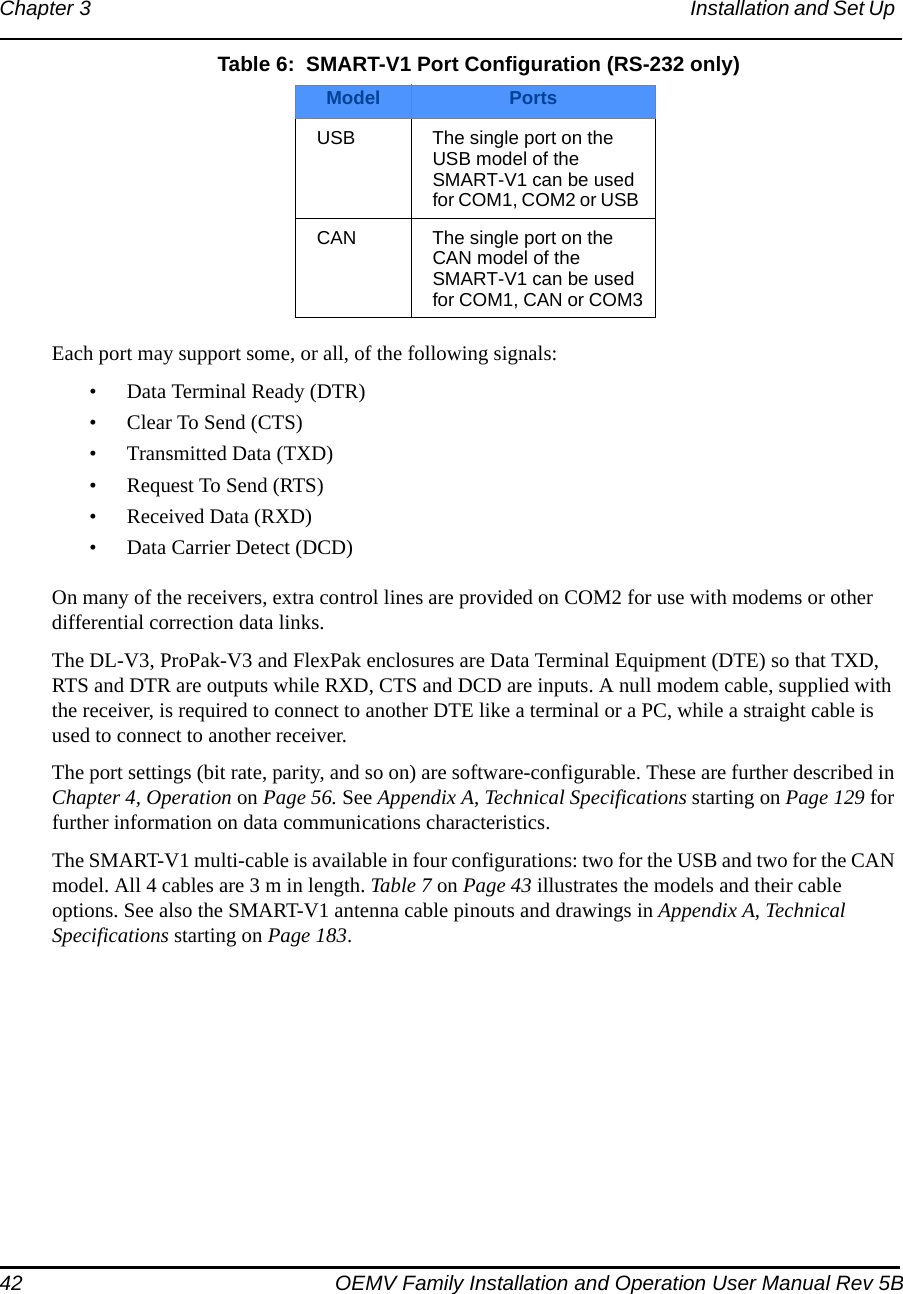
![58 OEMV Family Installation and Operation User Manual Rev 5BChapter 4 Operation 4.2 Getting StartedIncluded with your receiver are NovAtel’s CDU and Convert programs. CDU is a windows-based GUI which allows you to access the receiver's many features without the need for communications protocol or to write special software. The Convert utility is a windows-based utility that allows you to convert between file formats, and strips unwanted records for data file compilation. See Chapter 6, PC Software and Firmware on Page 99 for more information on these programs and their installation.4.2.1 Starting the ReceiverThe receiver’s software resides in flash memory. When first powered, it undergoes a complete self-test. If an error condition is detected during a self-test, the self-test status word changes. This self-test status word can be viewed in the header of any data output log. Refer to the chapter on Messages in the OEMV Firmware Reference Manual for header information. If a persistent error develops, please contact your local NovAtel dealer first. If the problem is still unresolved, please contact NovAtel directly through any of the methods in the Customer Service section at the beginning of this manual on Page 18.4.2.2 Communicating with the Receiver Using CDULaunch the CDU program and select Device | Open from its main menu. The Open Configuration window appears. The example below shows an Open Configuration window with two possible configurations already set up. Your configurations may be different or you may have none at all, in which case, the Open Configuration window is empty.Refer to CDU’s Help file by selecting the Help | Contents menu. See also Chapter 6, PC Software and Firmware starting on Page 99 for descriptions of the CDU windows available from the View menu. Ensure you can see the Console and ASCII Messages windows by selecting them from the View menu.When the receiver is first turned on, no data is transmitted from the COM ports except for the port prompt. The Console window displays a port name:[COM1] if connected to COM1 port,[COM2] if connected to COM2 port,](https://usermanual.wiki/Novatel/01017829.User-Manual-part-1/User-Guide-777993-Page-58.png)
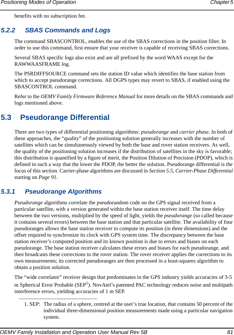
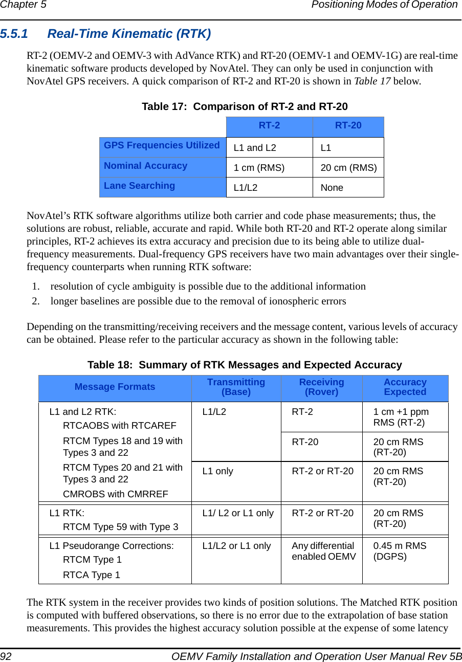
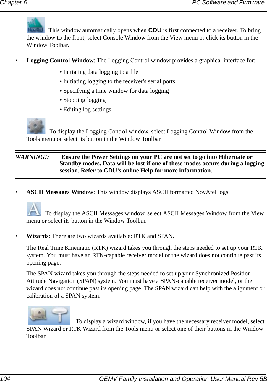
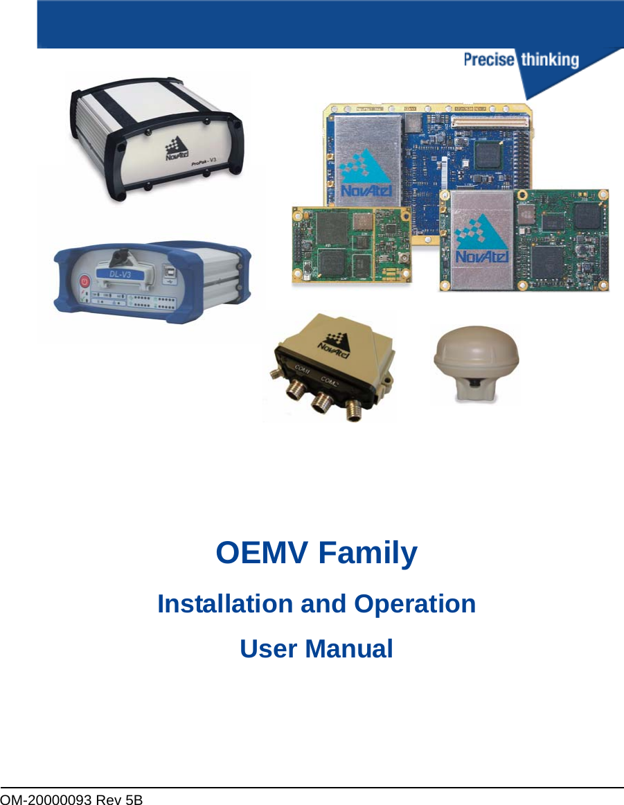
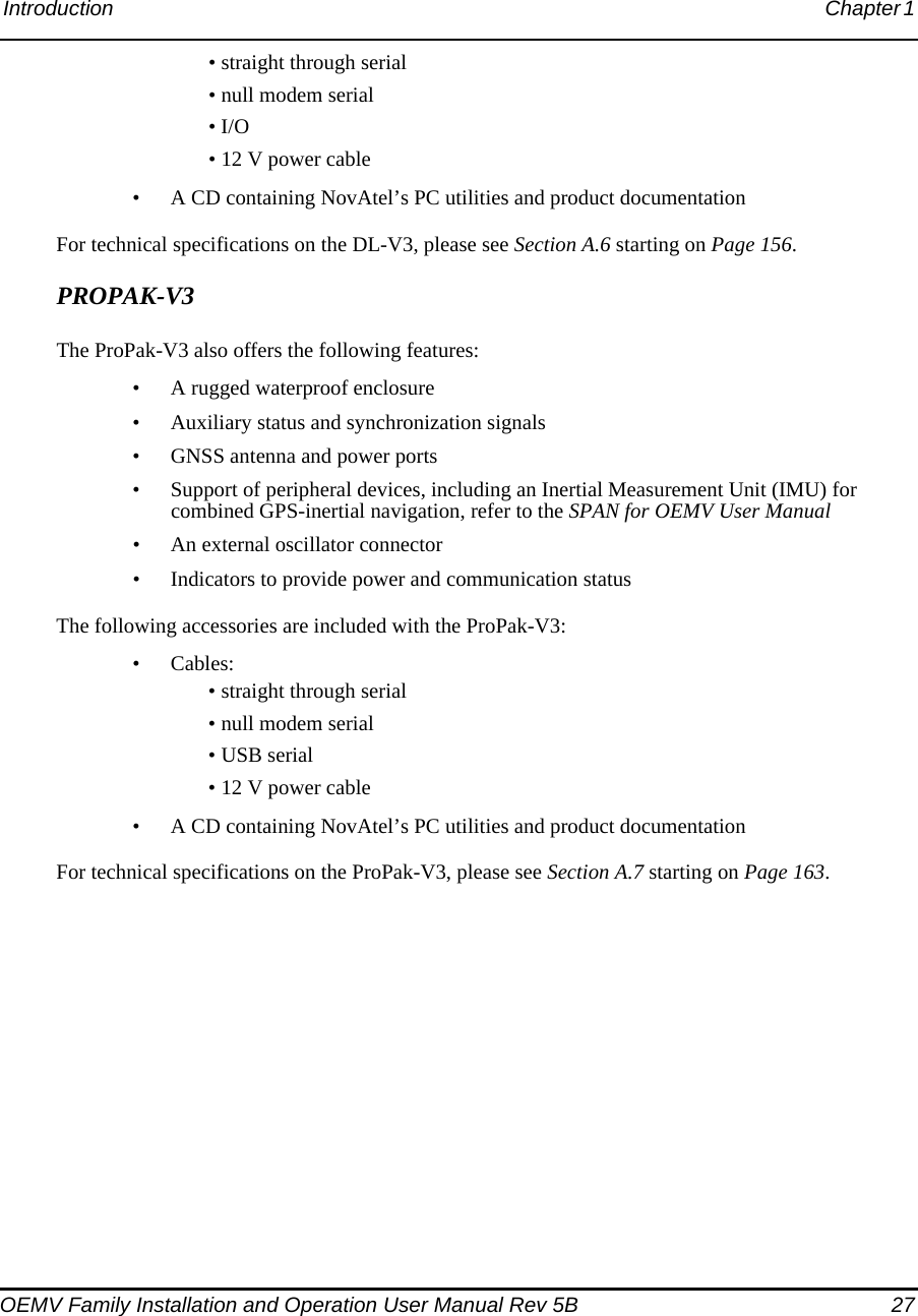
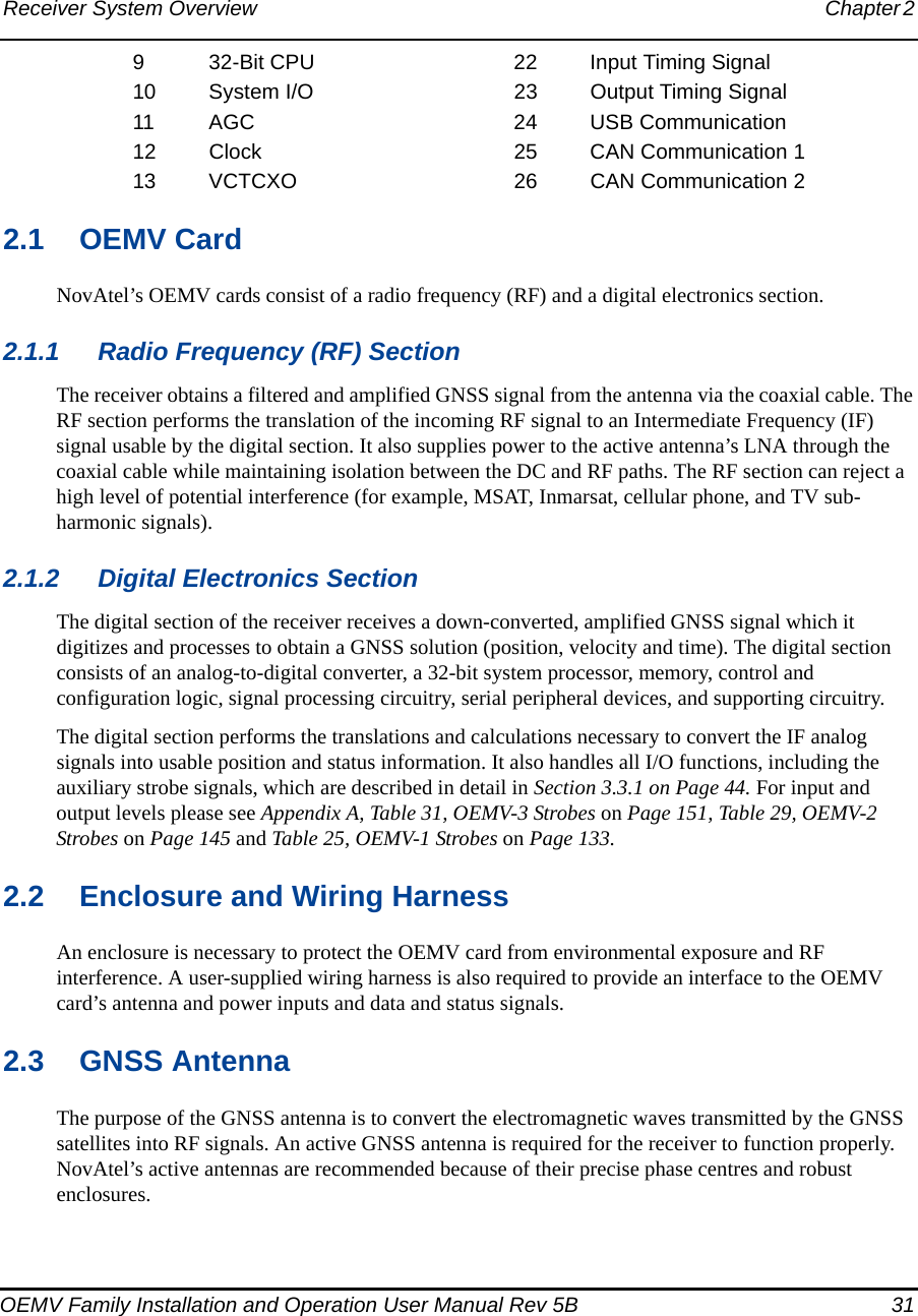
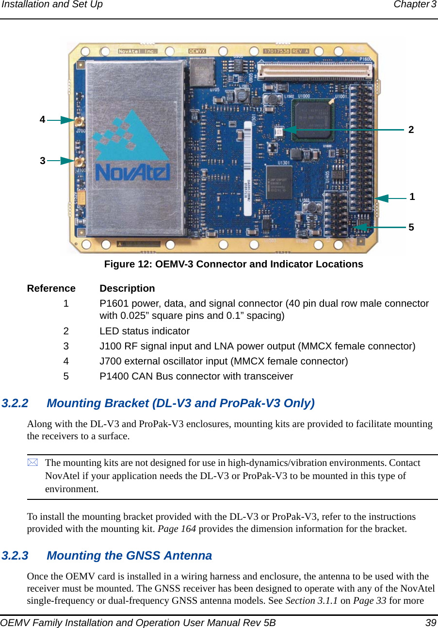
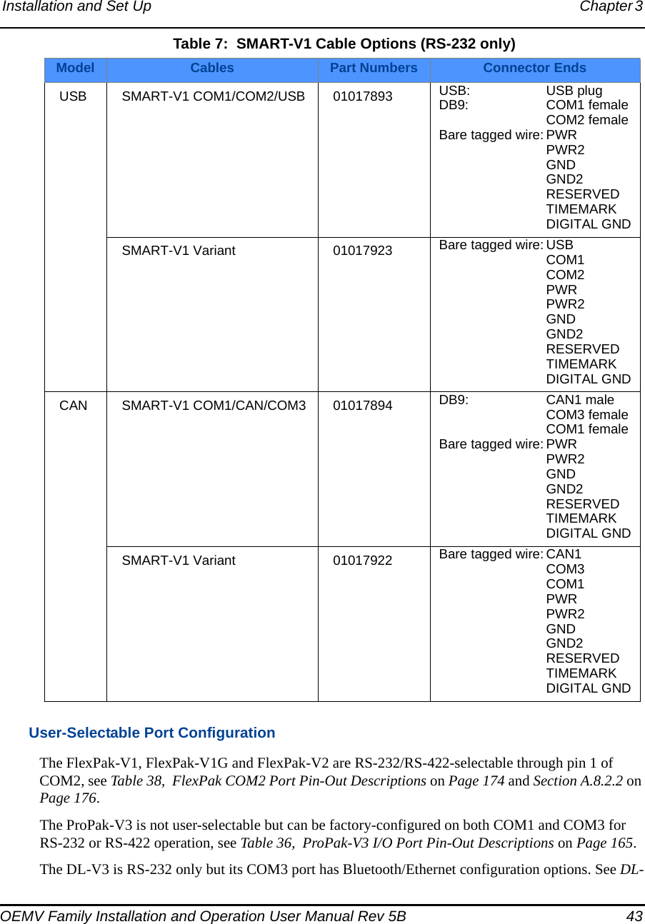
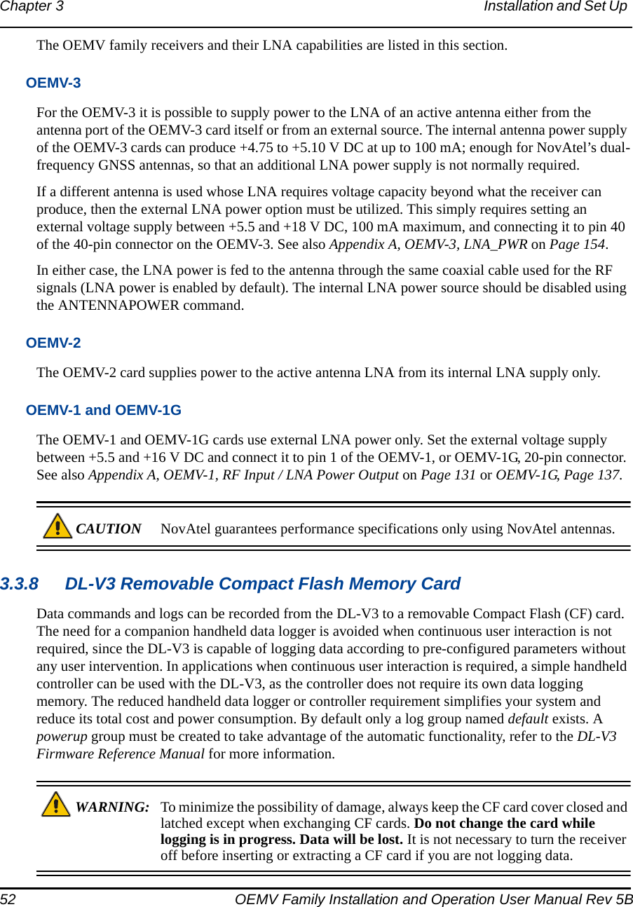
![Operation Chapter 4 OEMV Family Installation and Operation User Manual Rev 5B 59or[COM3] if connected to COM3 portAny of the above prompts indicate that the receiver is ready and waiting for command input. The screen may display other port names for other port types, for example USB1, USB2, USB3 or AUX. 1. You may also have to wait for output from receiver self tests. For example, on start-up, the OEMV family receiver is set to log the RXSTATUSEVENTA log ONNEW on all ports. See Section 7.4, RXSTATUSEVENT Log on Page 119 for more details.2. If you find that CDU is unable to locate your OEMV family receiver, it may be that you have previously used the SAVECONFIG command. In this case, try using a different COM port to communicate to the receiver. Once communication has been established, issue a FRESET STANDARD command. You should now be able to use your original communication port again.3. XCOM1, XCOM2 and XCOM3 virtual ports can be generated by the receiver. However they are unlikely to appear as a port prompt as you cannot connect to these types of ports using CDU. Also, they are not available with the COM command but may be used with other commands, such as INTERFACEMODE and LOG. Refer to the OEMV Firmware Reference Manual for the virtual ports available and details on the above mentioned logs.Commands are typed at the interfacing computing device’s keypad or keyboard, and executed after issuing a carriage return command which is usually the same as pressing the <Enter> key.An example of a response to an input command is the FIX POSITION command. It can be as:[COM2] fix position 51.11635 -114.0383 1048.2 [carriage return]<OKwhere [COM2] is the port prompt, followed by the command you enter from your keypad or keyboard and [carriage return] indicates that you should press the <Enter> key.The above example illustrates command input to the base receiver’s COM2 port which sets the position of the base station receiver for differential operation. Confirmation that the command was actually accepted is the appearance of <OK.If a command is entered incorrectly, the receiver responds with:<INVALID MESSAGE ID (or a more detailed message)WARNING!: Ensure the Control Panel’s Power Settings on your PC are not set to go into Hibernate or Standby modes. Data will be lost if one of these modes occurs during a logging session.](https://usermanual.wiki/Novatel/01017829.User-Manual-part-1/User-Guide-777993-Page-59.png)
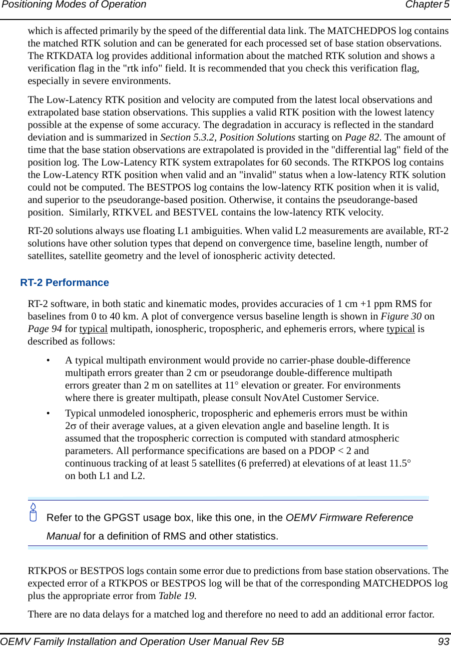
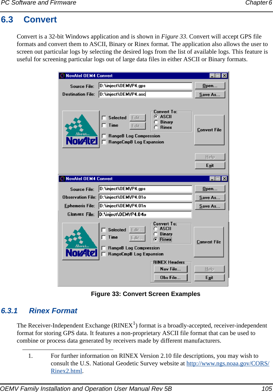
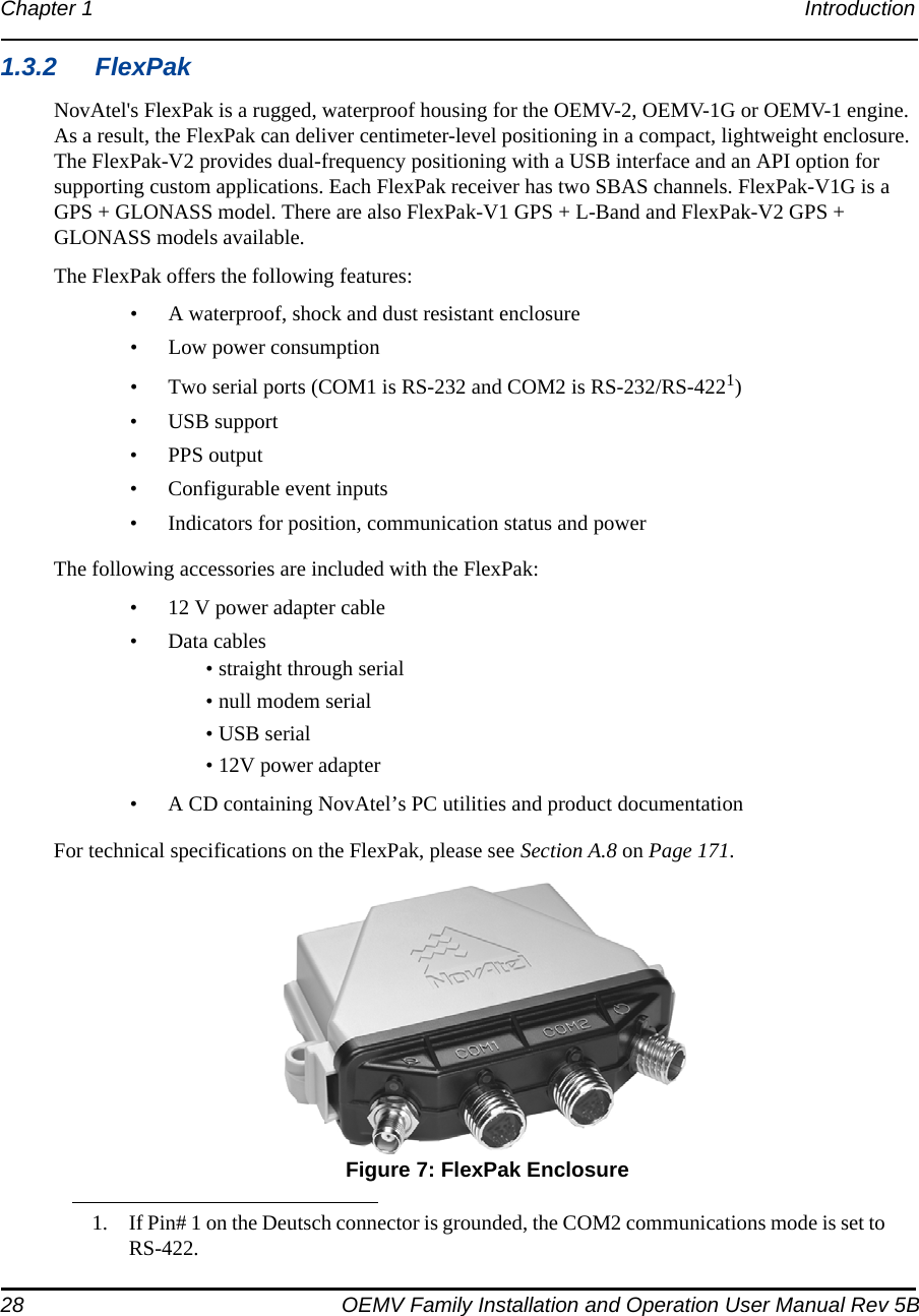
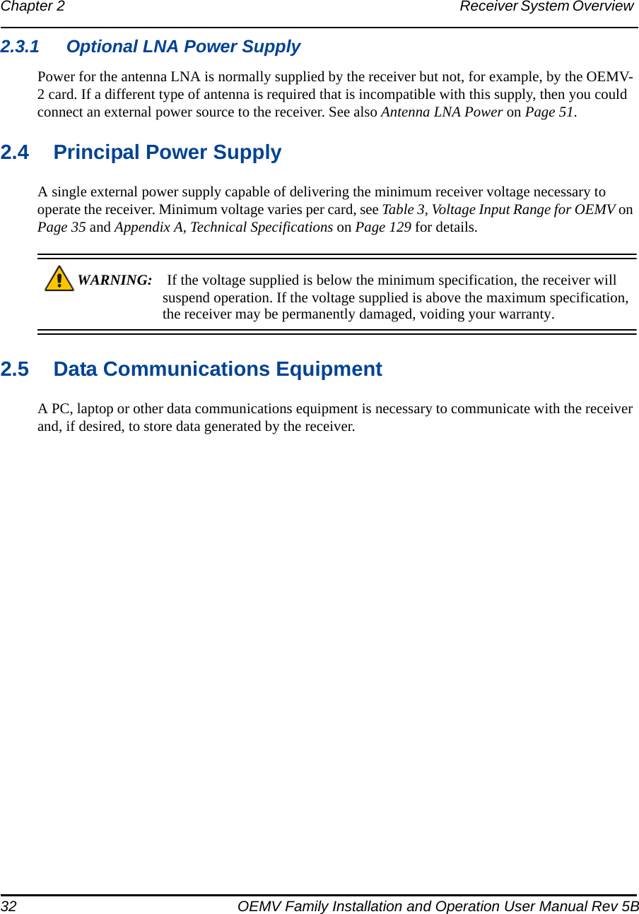
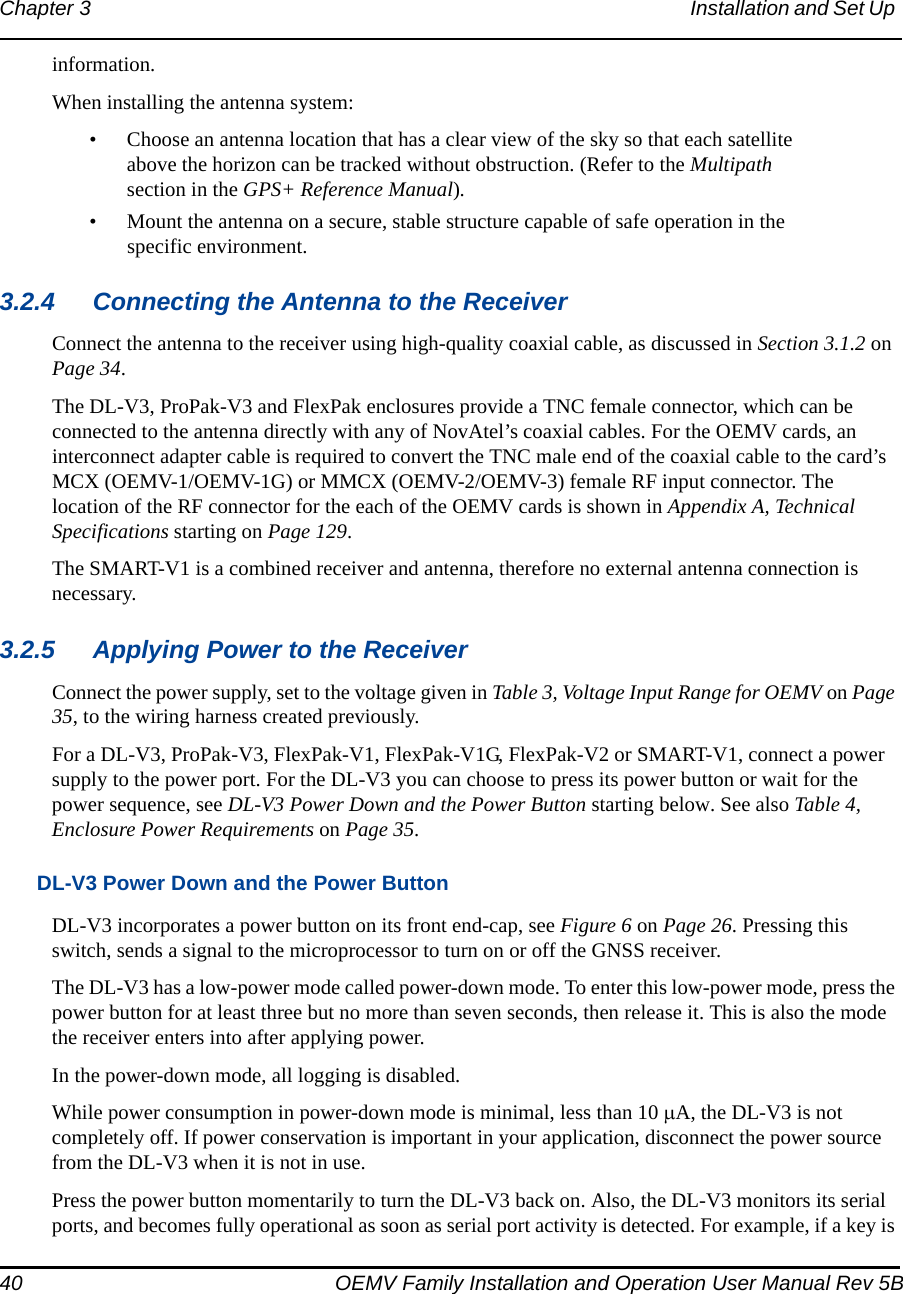
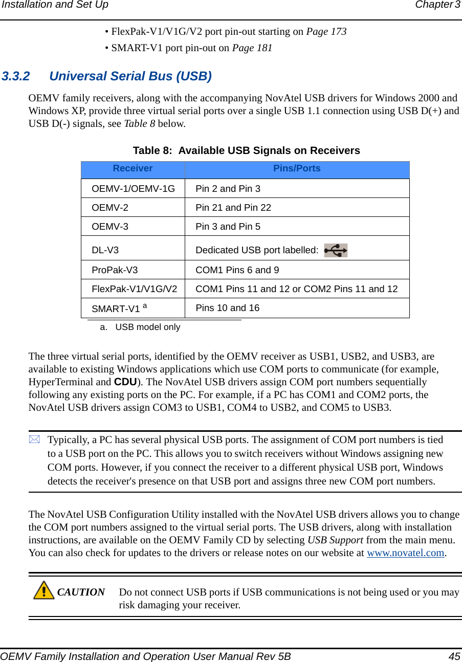
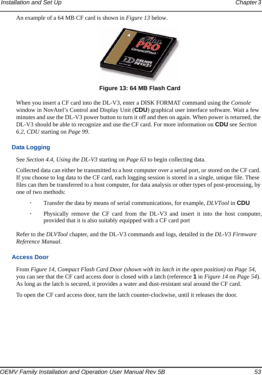
![Operation Chapter 4 OEMV Family Installation and Operation User Manual Rev 5B 61of data throughput at a rate of 9600 bits per second, and less than 4.0 s latency, is recommended. Once your base and rover are set up, you can configure them as shown in the configuration examples that follow in Sections 4.3.1 - 4.3.2 starting on Page 62.4.3.1 Base Station ConfigurationAt the base station, enter the following commands:interfacemode port rx_type tx_type [responses]fix position latitude longitude heightlog port message [trigger [period]]For example:RTCA interfacemode com2 none rtca offfix position 51.11358042 -114.04358013 1059.4105log com2 rtcaobs ontime 1log com2 rtcaref ontime 10log com2 rtca1 ontime 5log com2 rtcaephem ontime 10 1 (optional)RTCM interfacemode com2 none rtcm offfix position 51.11358042 -114.04358013 1059.4105log com2 rtcm3 ontime 10log com2 rtcm22 ontime 10 1log com2 rtcm1819 ontime 1log com2 rtcm1 ontime 5RTCMV3 interfacemode com2 none rtcmv3 offfix position 51.11358042 -114.04358013 1059.4105log com2 rtcm1006 ontime 10log com2 rtcm1003 ontime 1CMR+ interfacemode com2 none cmr offfix position 51.11358042 -114.04358013 1059.4105log com2 cmrobs ontime 1log com2 cmrplus ontime 1 (important to use ontime 1 with cmrplus)CMR interfacemode com2 none cmr offfix position 51.11358042 -114.04358013 1059.4105](https://usermanual.wiki/Novatel/01017829.User-Manual-part-1/User-Guide-777993-Page-61.png)
![62 OEMV Family Installation and Operation User Manual Rev 5BChapter 4 Operation log com2 cmrobs ontime 1log com2 cmrref ontime 10log com2 cmrdesc ontime 10 14.3.2 Rover Station ConfigurationAt the rover station, enter:interfacemode port rx_type tx_type [responses]For example:RTCA interfacemode com2 rtca none offRTCM interfacemode com2 rtcm none offRTCMV3 interfacemode com2 rtcmv3 none offCMR+ interfacemode com2 cmr none offCMR interfacemode com2 cmr none off (same as CMR+)4.3.3 Configuration NotesFor compatibility with other GNSS receivers, and to minimize message size, it is recommended that you use the standard form of RTCA, RTCM, RTCMV3 or CMR corrections as shown in the base and rover examples above. This requires using the INTERFACEMODE command to dedicate one direction of a serial port to only that message type. When the INTERFACEMODE command is used to change the mode from the default, NOVATEL, you can no longer use NovAtel format messages.If you wish to mix NovAtel format messages and RTCA, RTCM, RTCMV3 or CMR messages on the same port, you can leave the INTERFACEMODE set to NOVATEL and log out variants of the standard correction messages with a NovAtel header. ASCII or binary variants can be requested by simply appending an "A" or "B" to the standard message name. For example on the base station:interfacemode com2 novatel novatelfix position 51.11358042 -114.04358013 1059.4105log com2 rtcm1b ontime 2Using the receiver in this mode consumes more CPU bandwidth than using the native differential messages as shown in Section 4.3.1, Base Station Configuration on Page 61.At the rover station you can leave the INTERFACEMODE default settings (interfacemode com2 novatel novatel). The rover receiver recognizes the default and uses the corrections it receives with a NovAtel header.The PSRDIFFSOURCE and RTKSOURCE commands set the station ID values which identify the base stations from which to accept pseudorange or RTK corrections respectively. They are useful](https://usermanual.wiki/Novatel/01017829.User-Manual-part-1/User-Guide-777993-Page-62.png)