Olympus Medical Systems RU2020 Endoscope Reprocessor User Manual GT9882 0100 fm10
Olympus Medical Systems Corp. Endoscope Reprocessor GT9882 0100 fm10
UserManual.wiki
>
Olympus Medical Systems
>
RU2020 User Manual
>
Operation Manual 2
Contents
1.
Operation Manual 1
2.
Operation Manual 2
3.
Operation Manual 3
4.
Operation Manual 4
5.
Operation Manual 5
6.
Installation Manual 1
7.
Installation Manual 2
Operation Manual 2
Navigation menu
Upload a User Manual
Namespaces
Wiki Guide
HTML
PDF
Info
Views
User Manual
Discussion / Help
Navigation
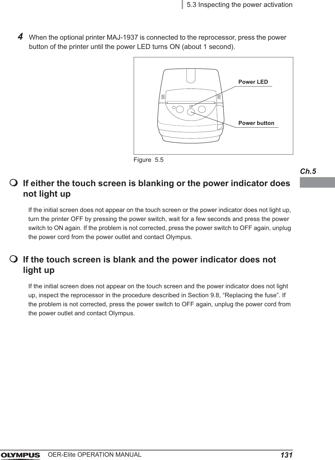
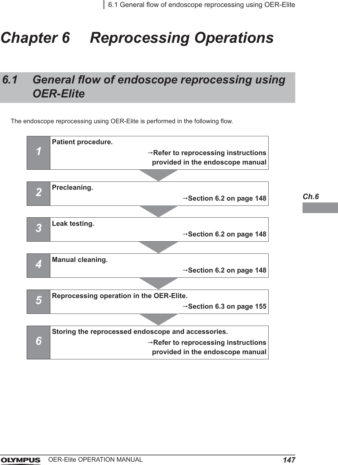
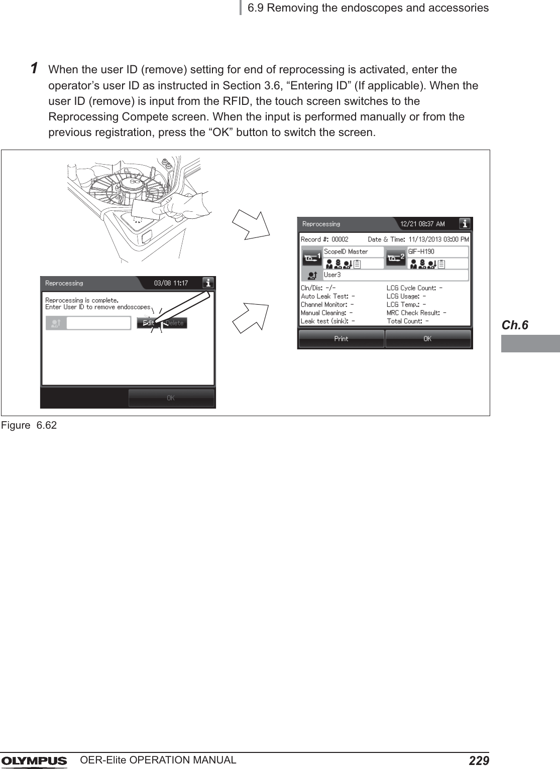
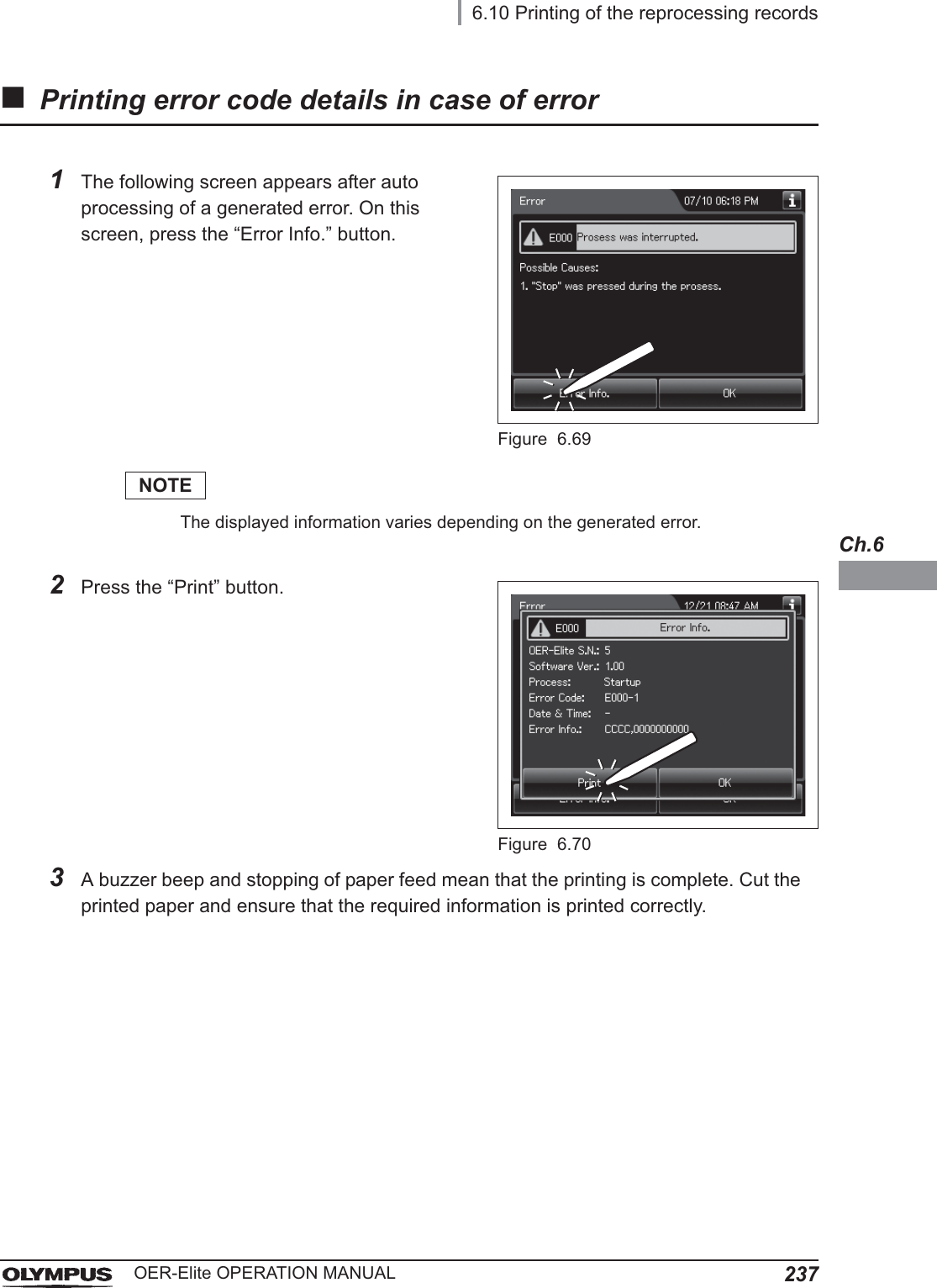
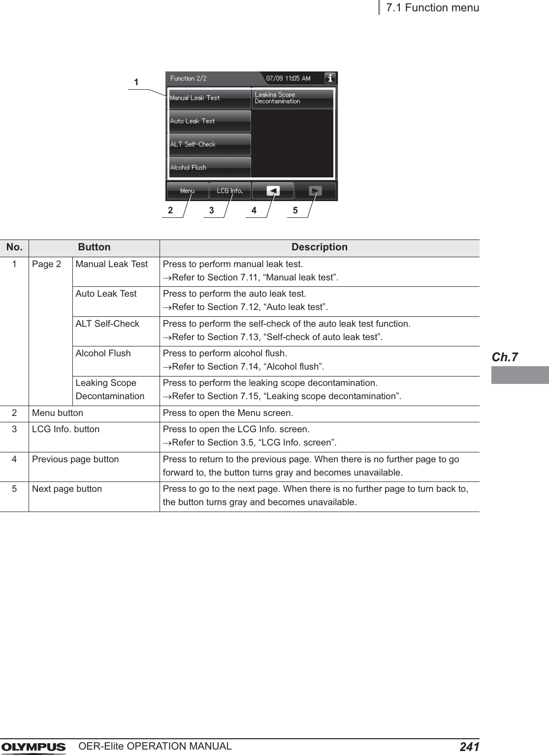
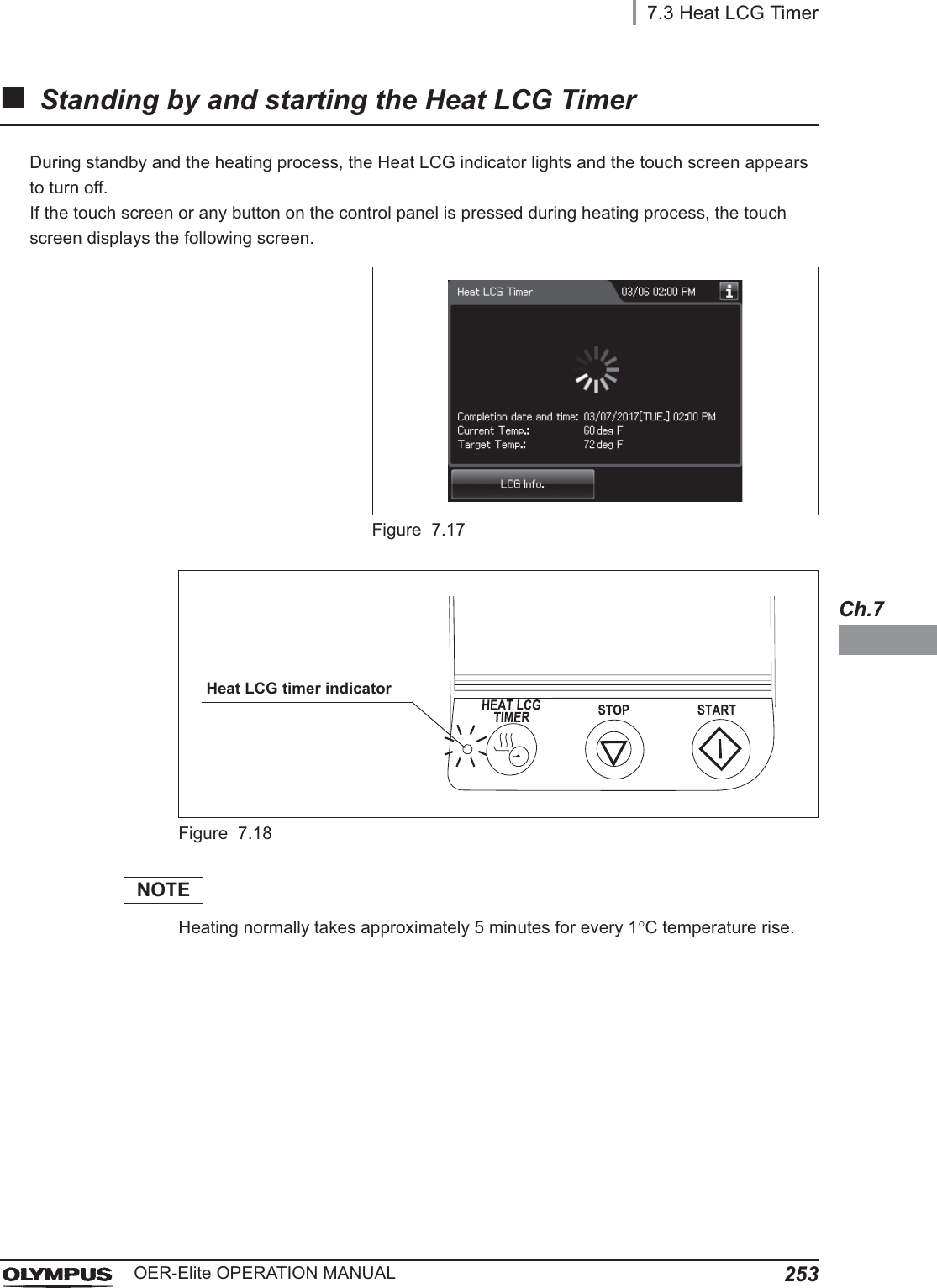
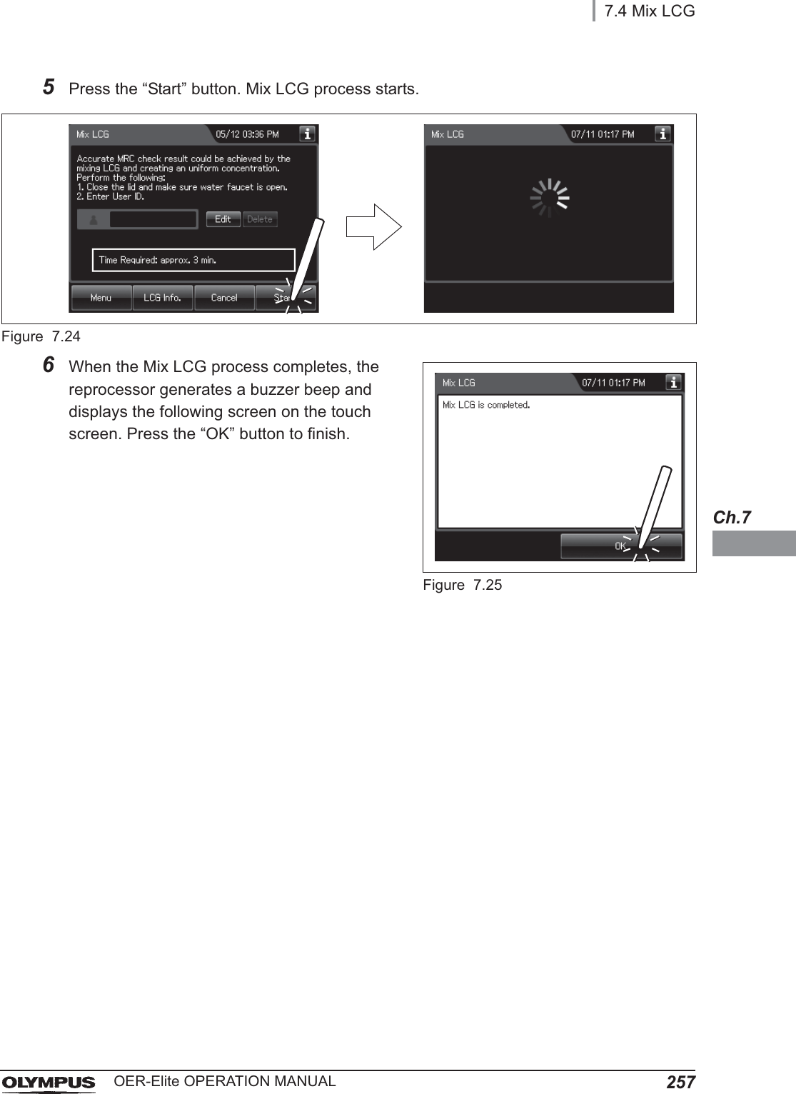
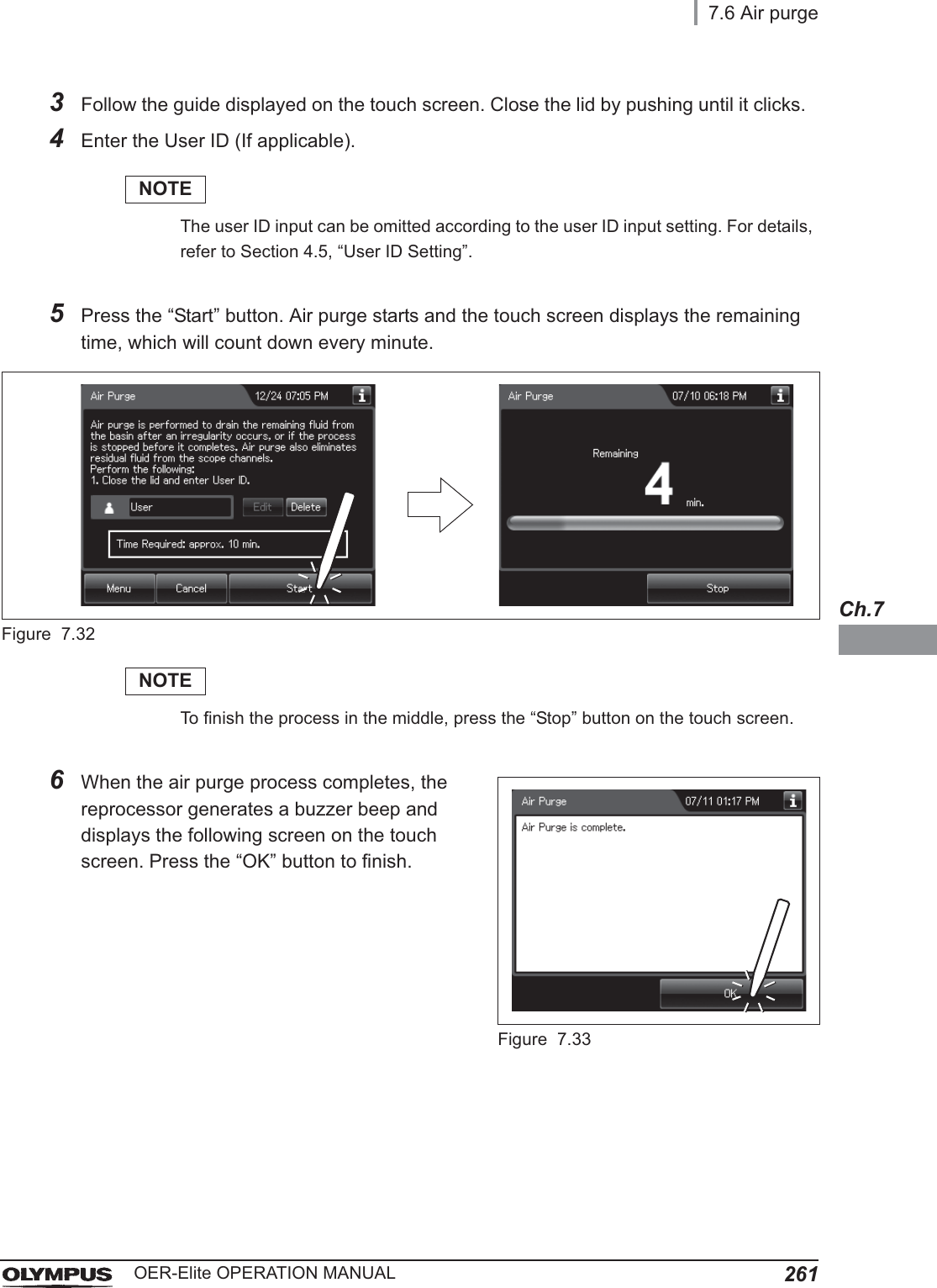
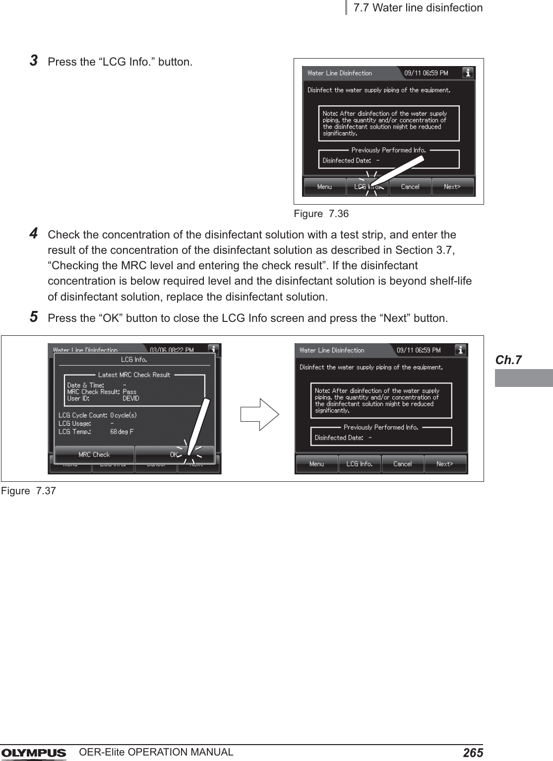
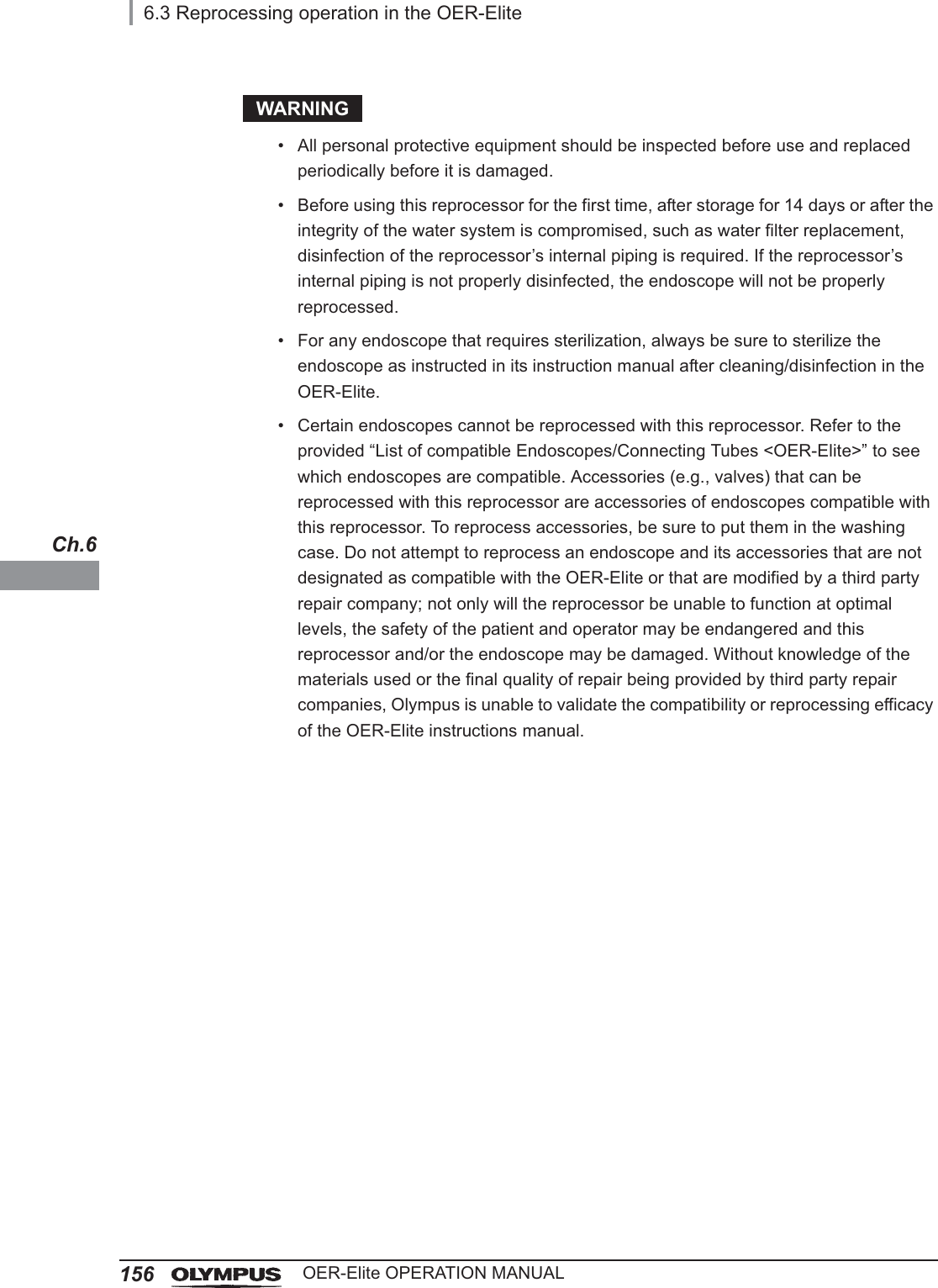
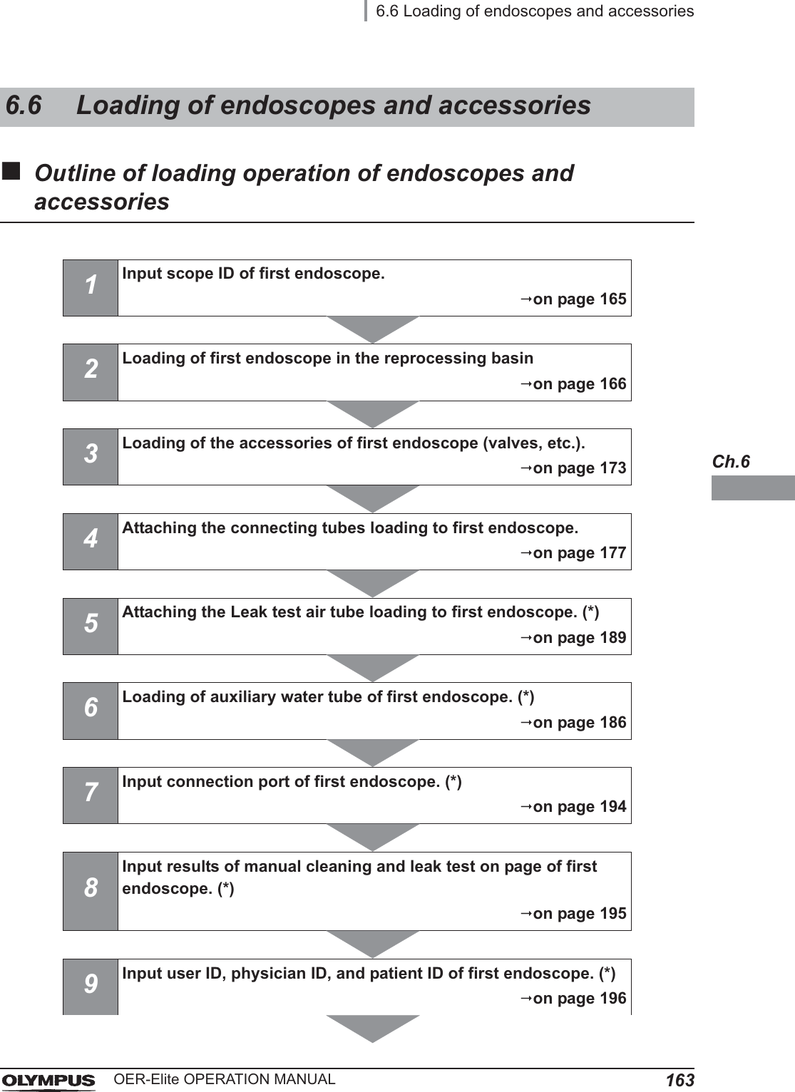
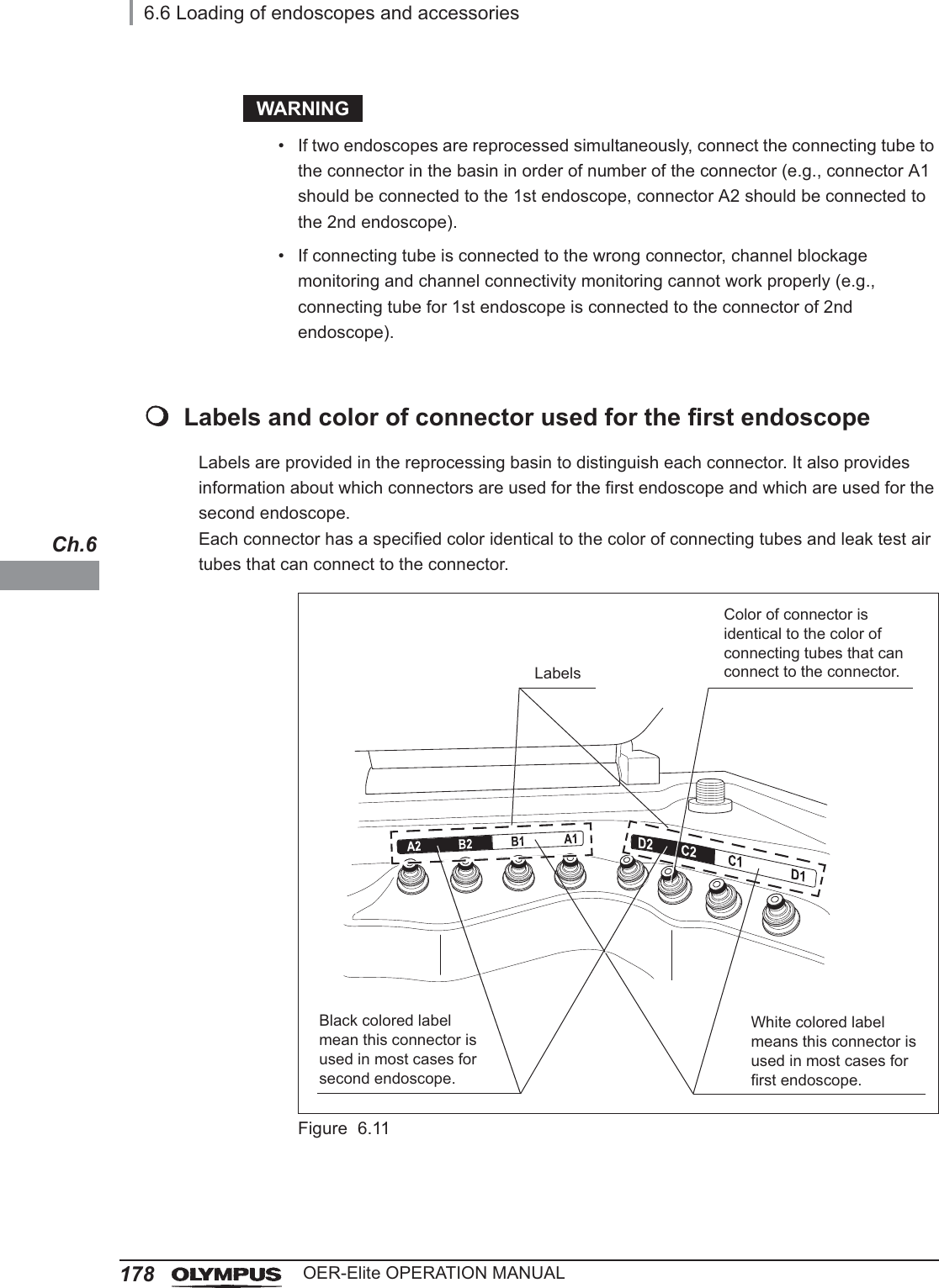
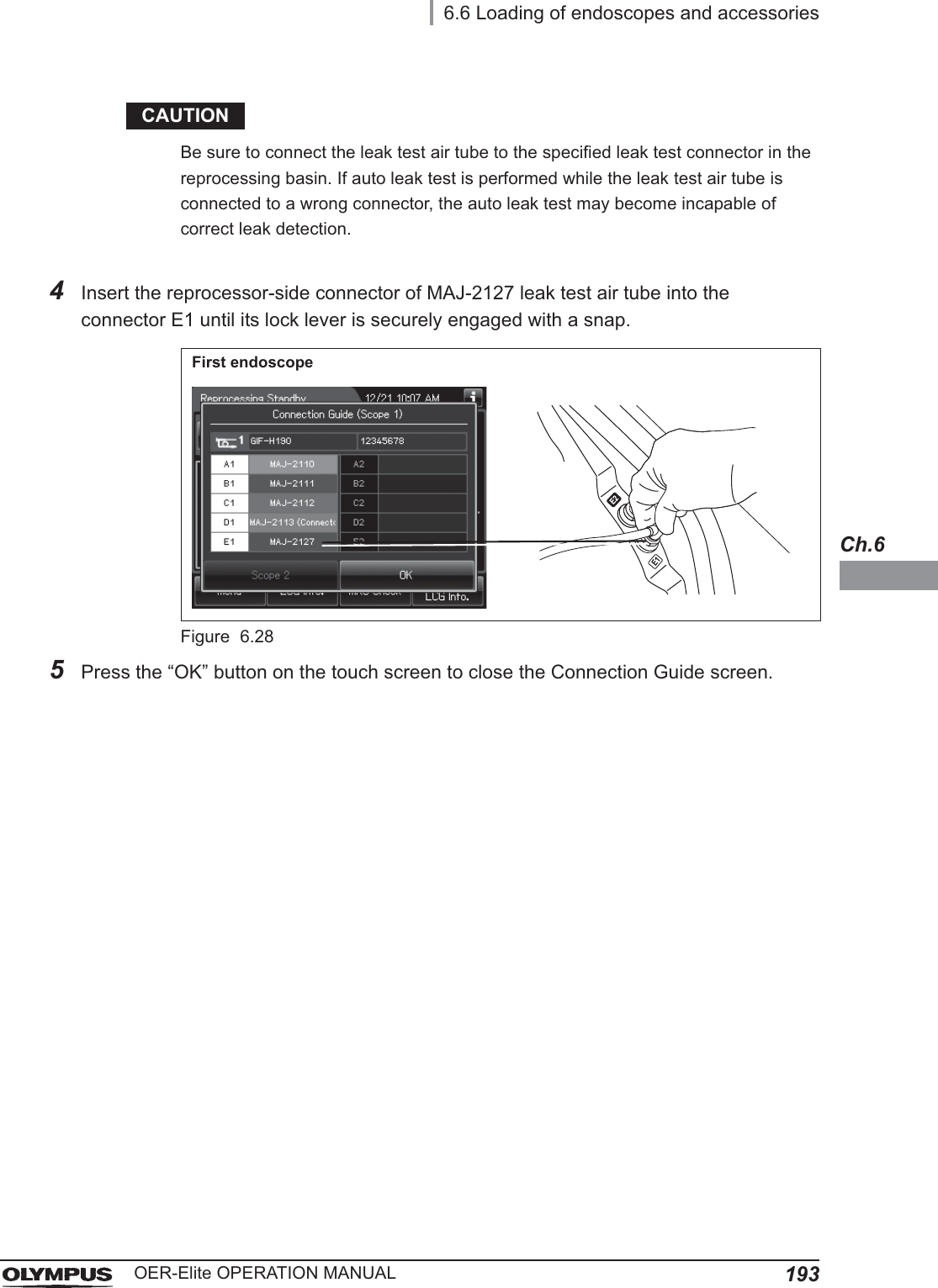
![1546.2 Precleaning, leak testing, and manual cleaningOER-Elite OPERATION MANUALCh.6Loading the endoscope and their accessories into the OER-EliteCarefully lift the endoscope out of the detergent solution, allowing excess fluid to drain into the basin. Carry the endoscope to the reprocessing basin of the OER-Elite. Place the endoscope in the reprocessing basin and connect the required connecting tube(s) to the endoscope. Place the valves in the washing case in the center of the retaining rack according to the instruction manual for the OER-Elite. Continue reprocessing, according to the instruction manual for the OER-Elite.CAUTION• Make sure that the detergent solution or water is not dripping from the endoscope after pulling the endoscope out of the detergent solution or water. Otherwise, unexpected interruption of reprocessing process by the OER-Elite may occur error code [E005], etc.• If detergent is used in the manual cleaning, rinse the endoscope thoroughly. Otherwise, detergent used in manual cleaning remains in the endoscopes and unexpected interruption of reprocessing process in the OER-Elite may occur.](https://usermanual.wiki/Olympus-Medical-Systems/RU2020.Operation-Manual-2/User-Guide-3575673-Page-26.png)
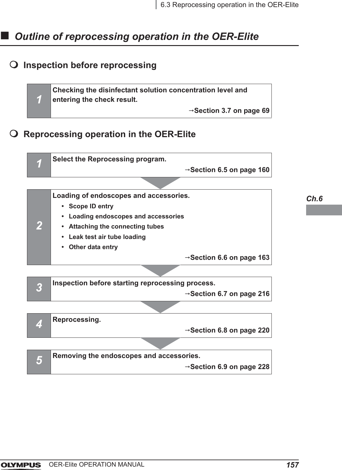
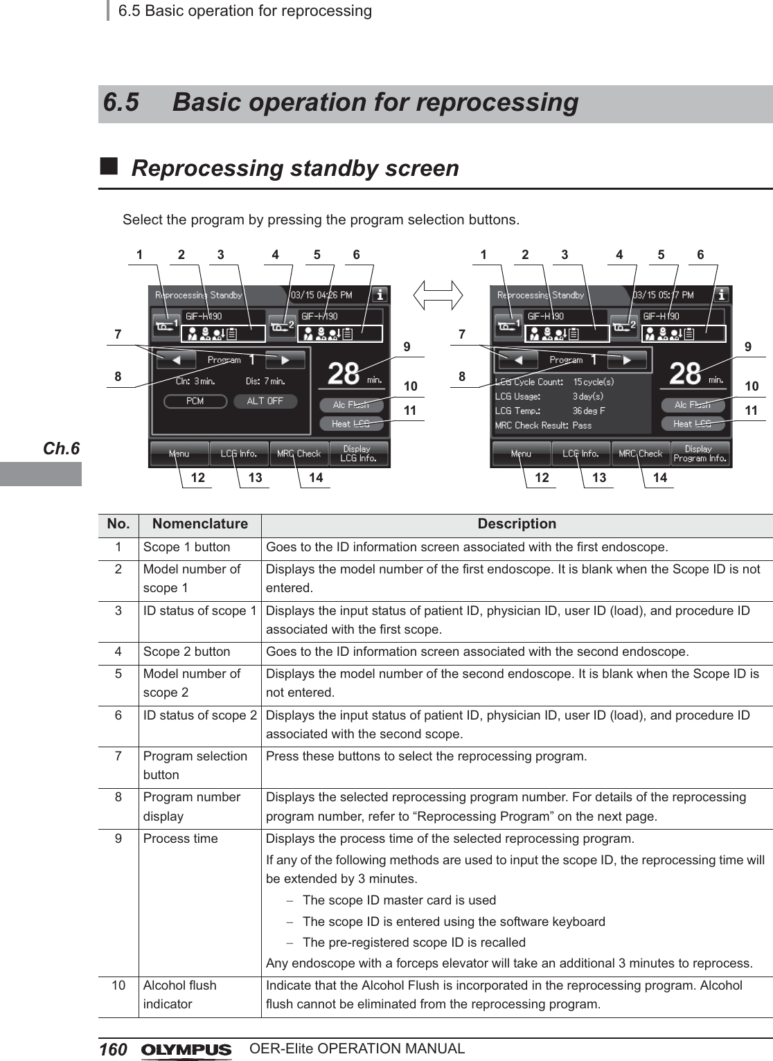
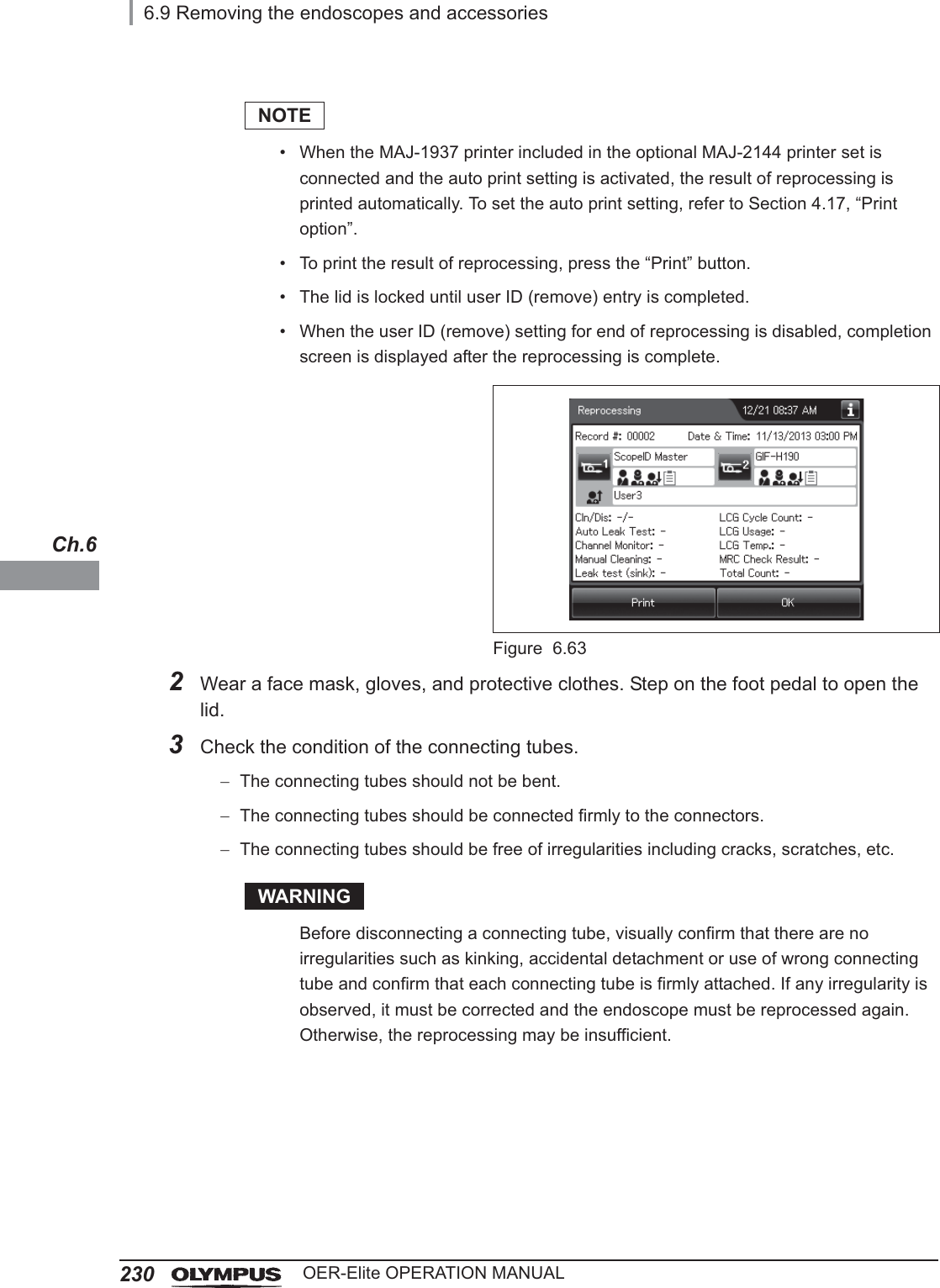
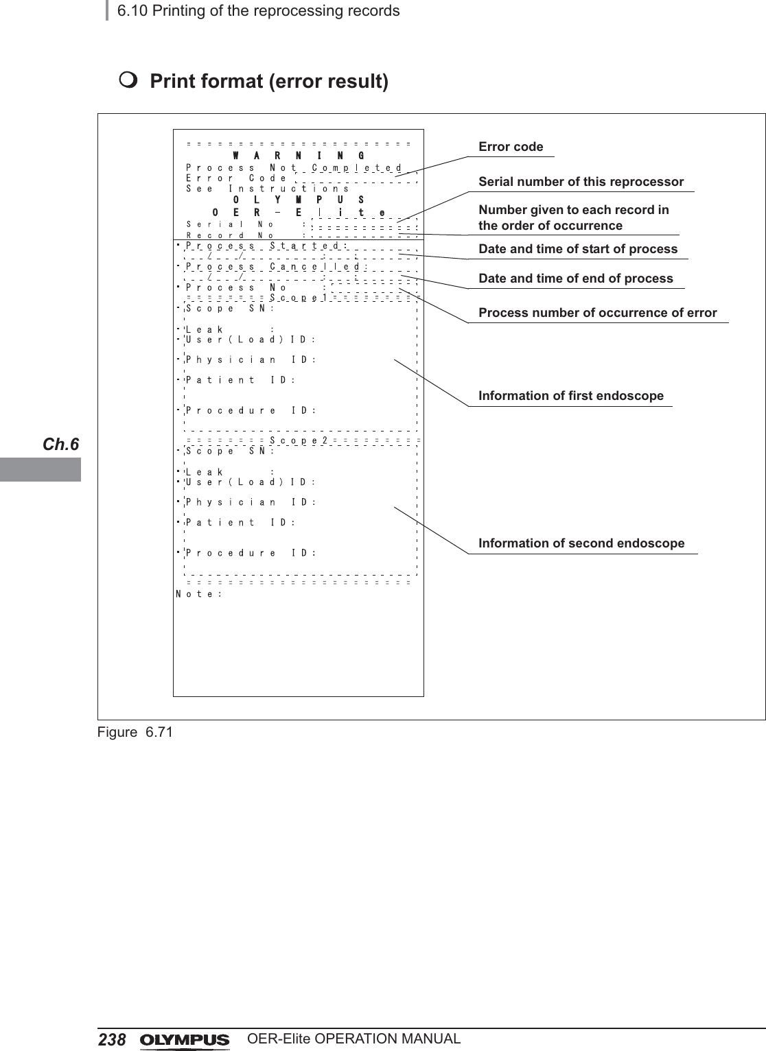
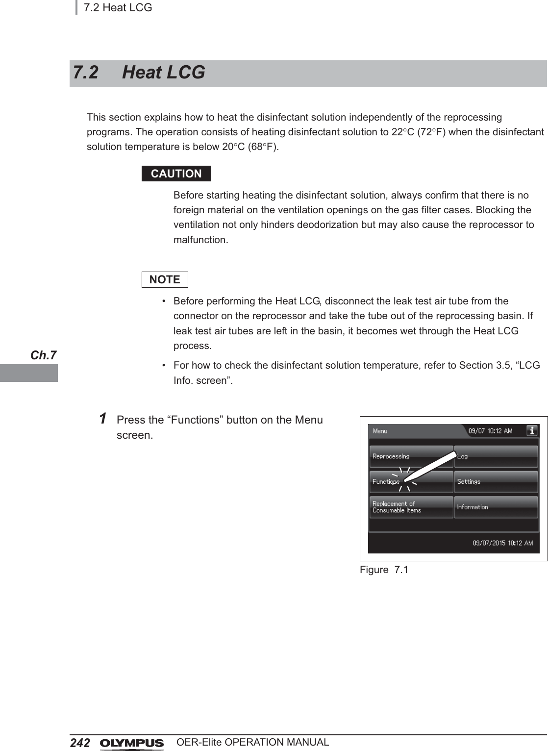
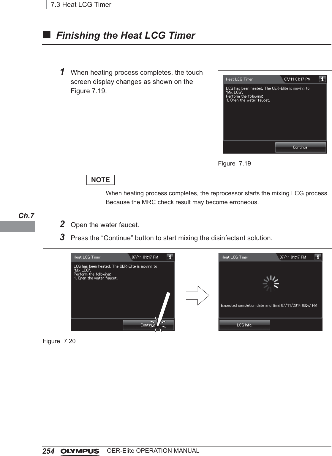
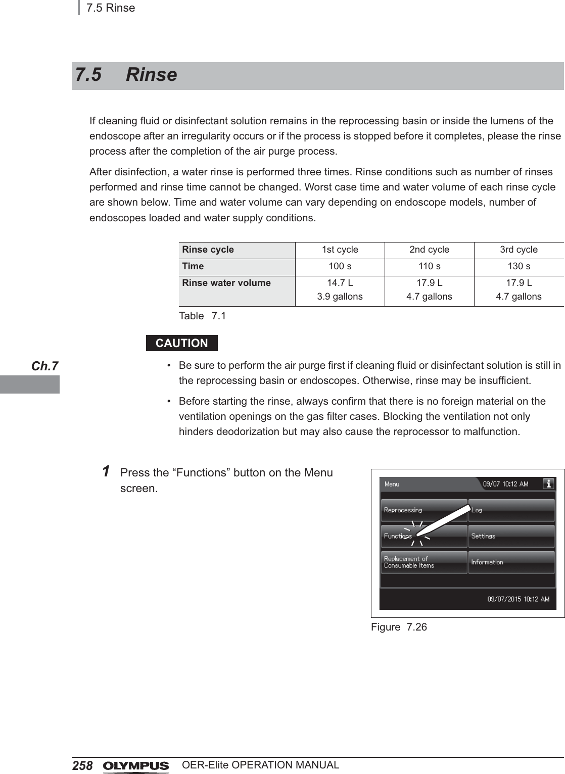
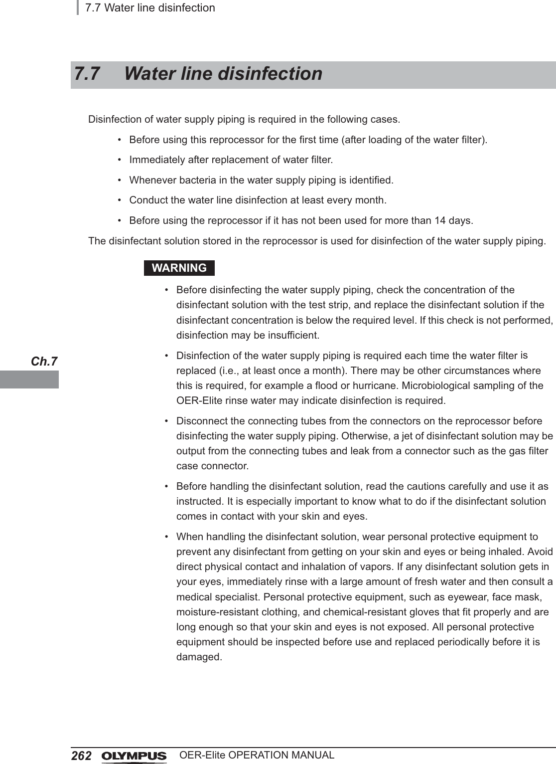
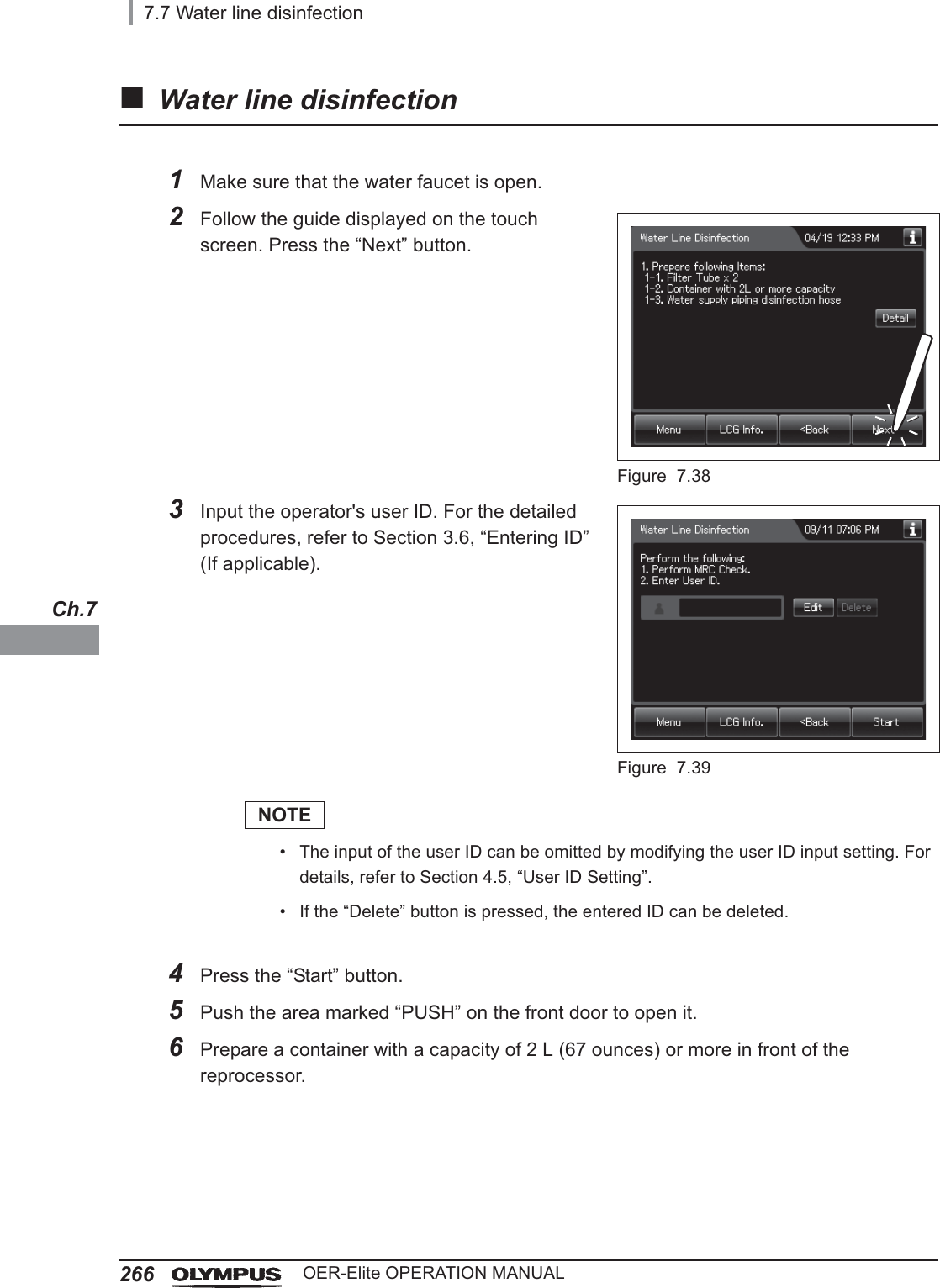
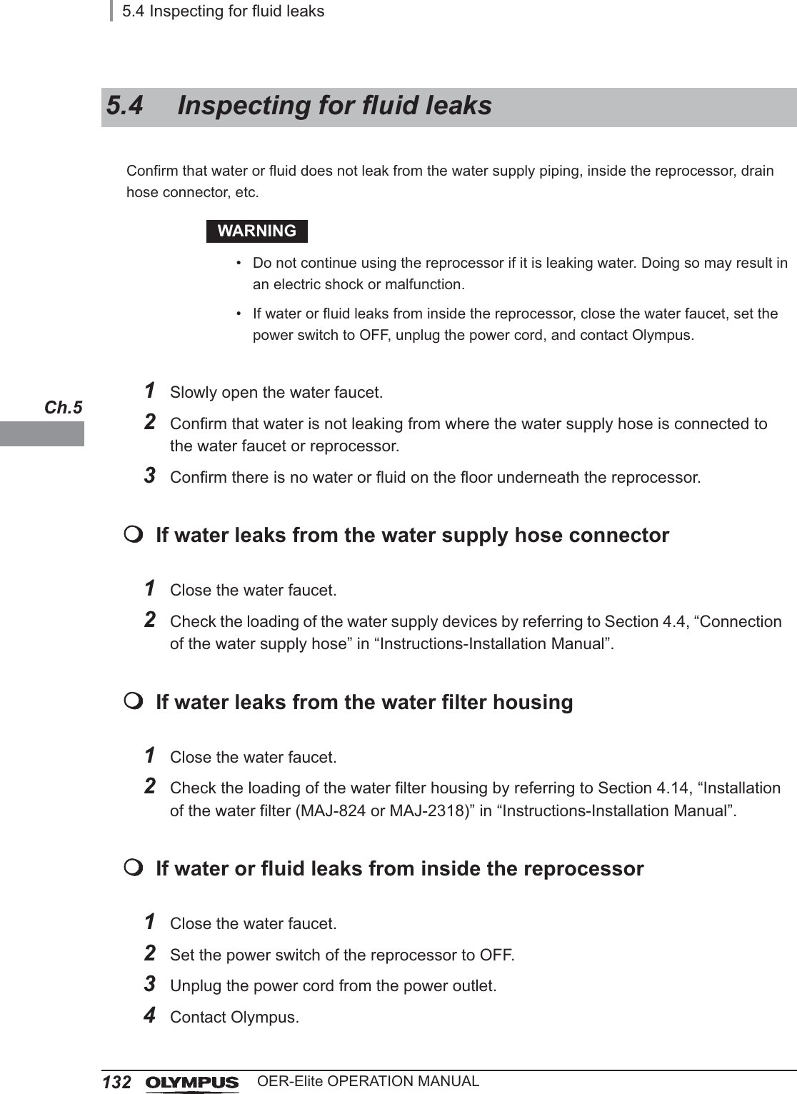
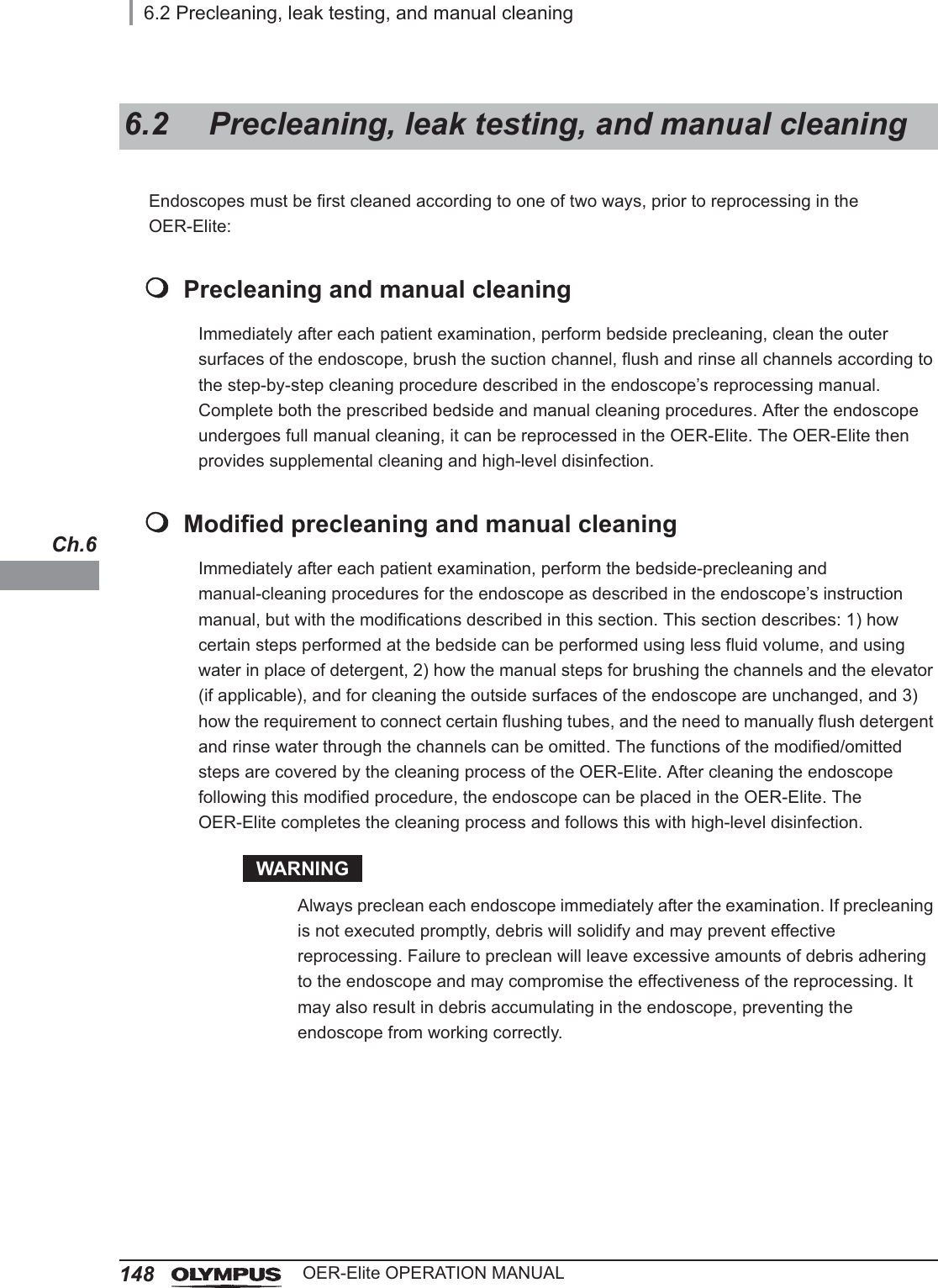
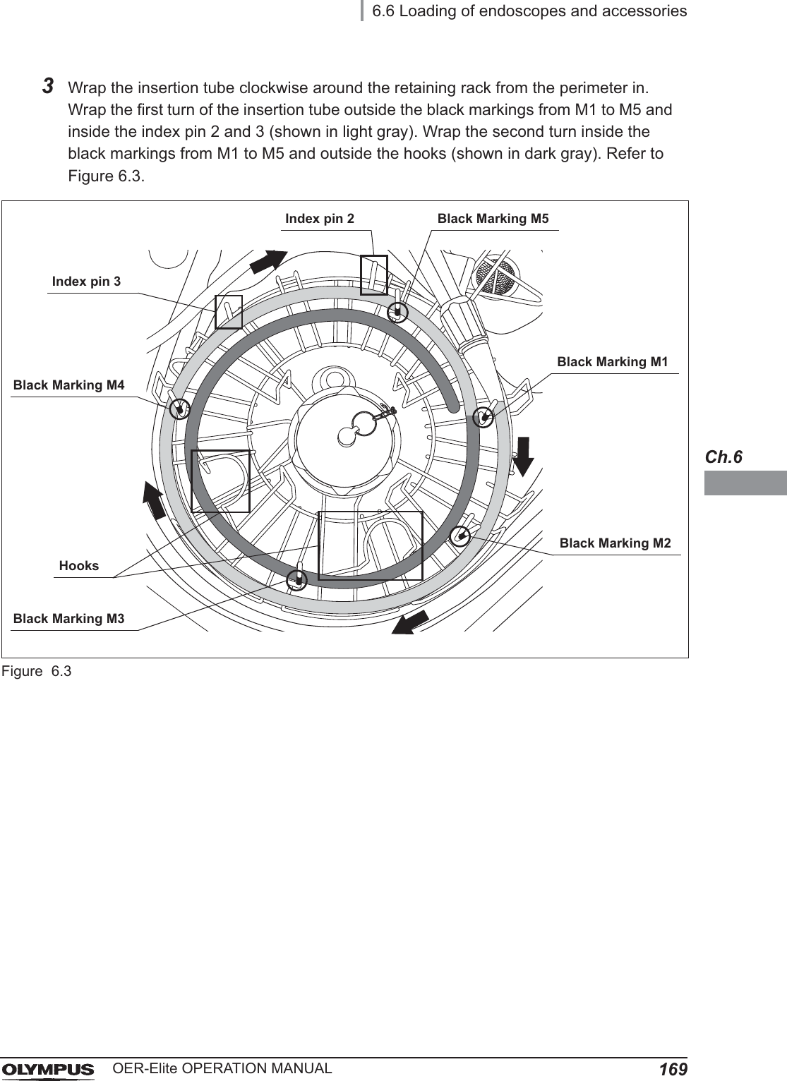
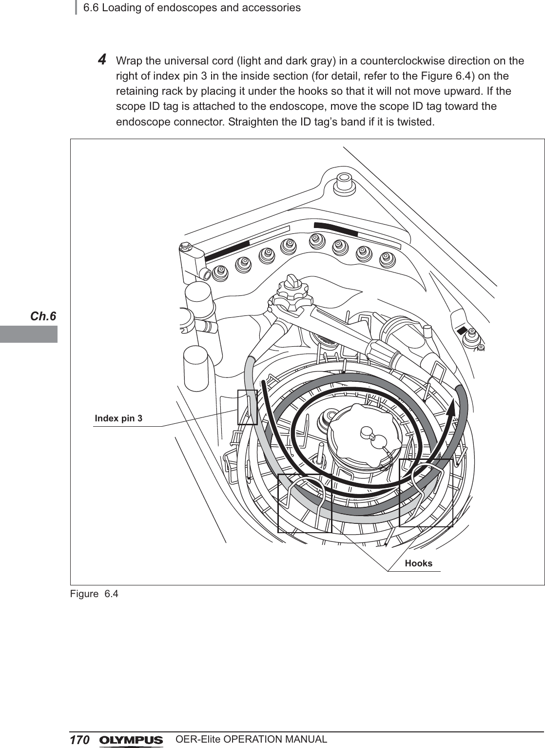
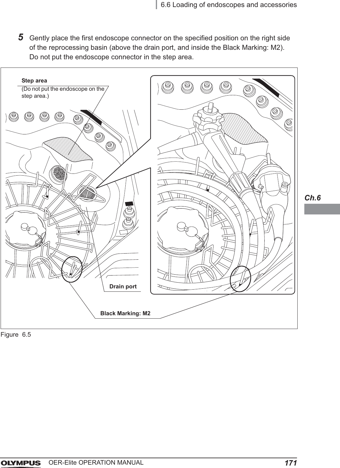
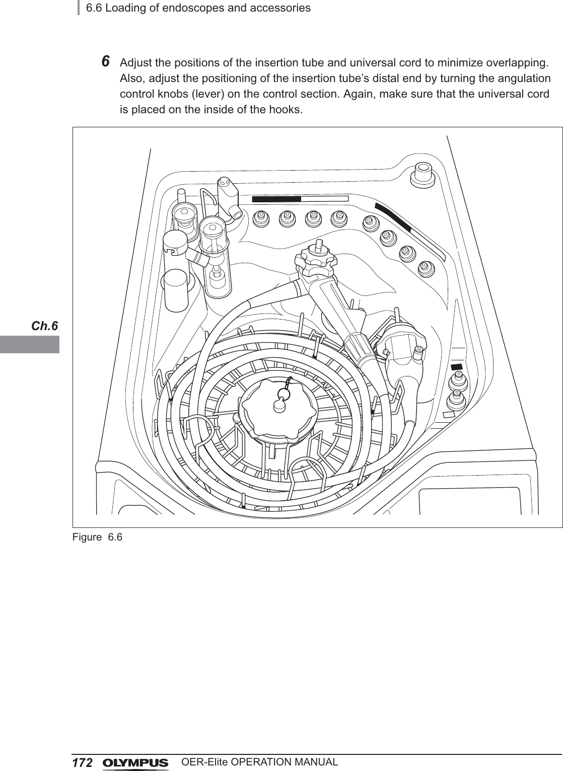
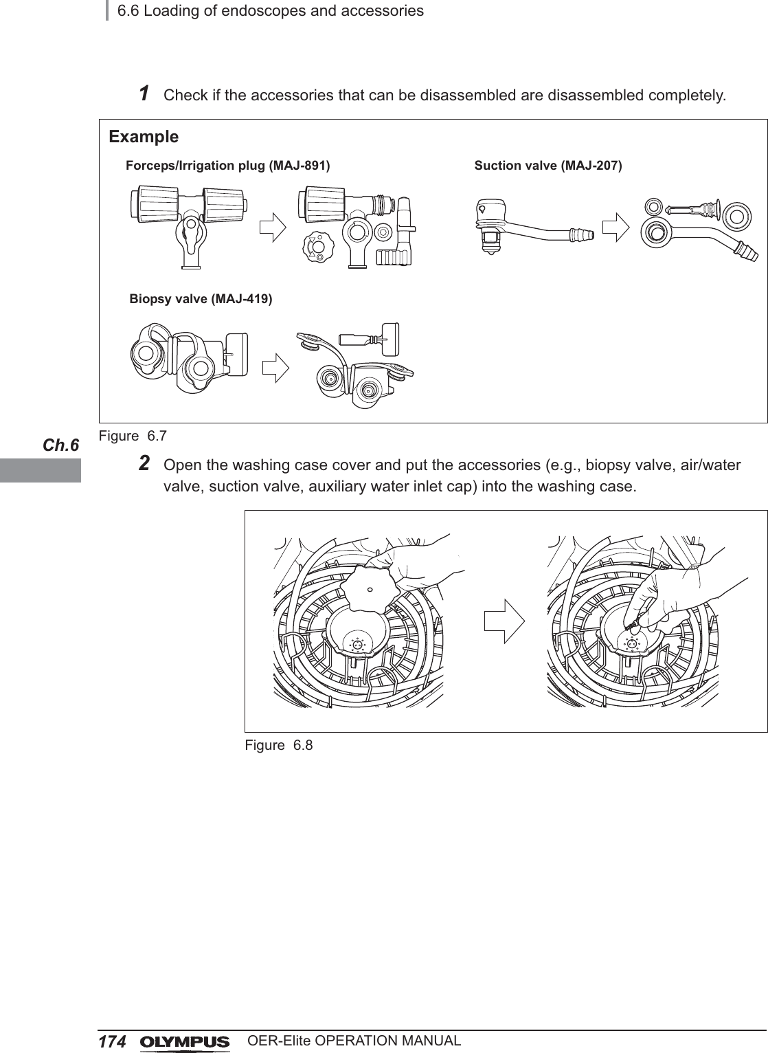
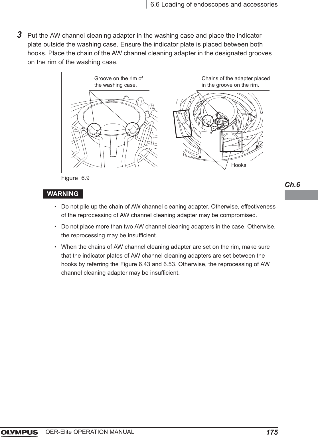
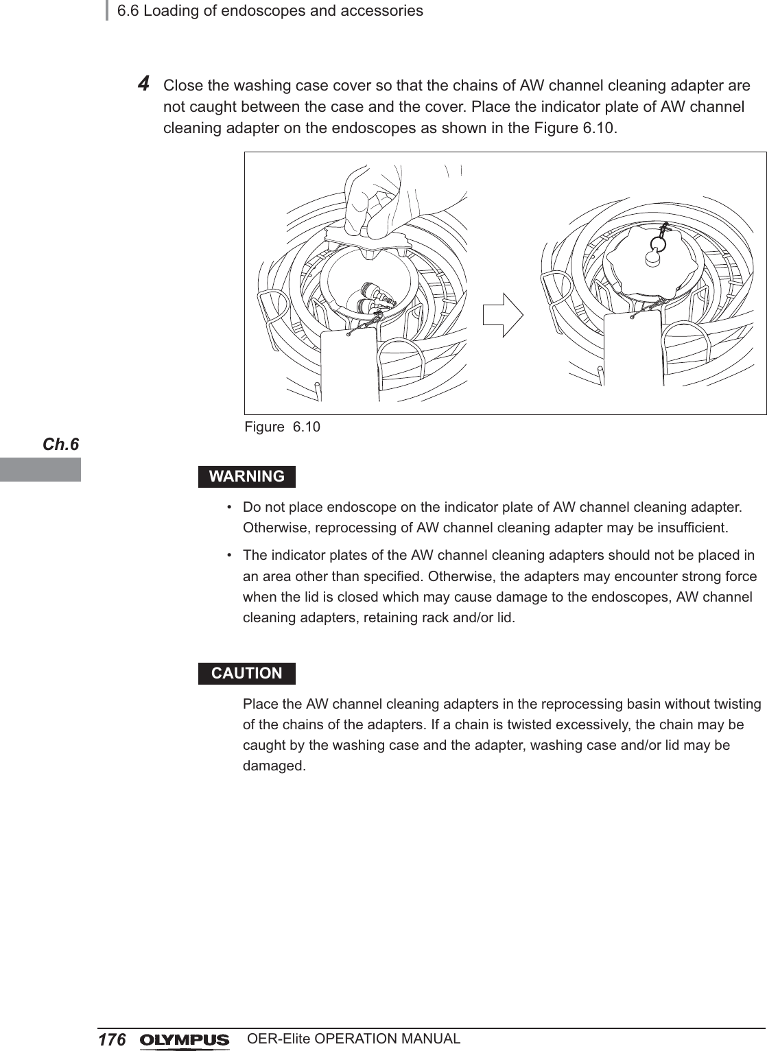
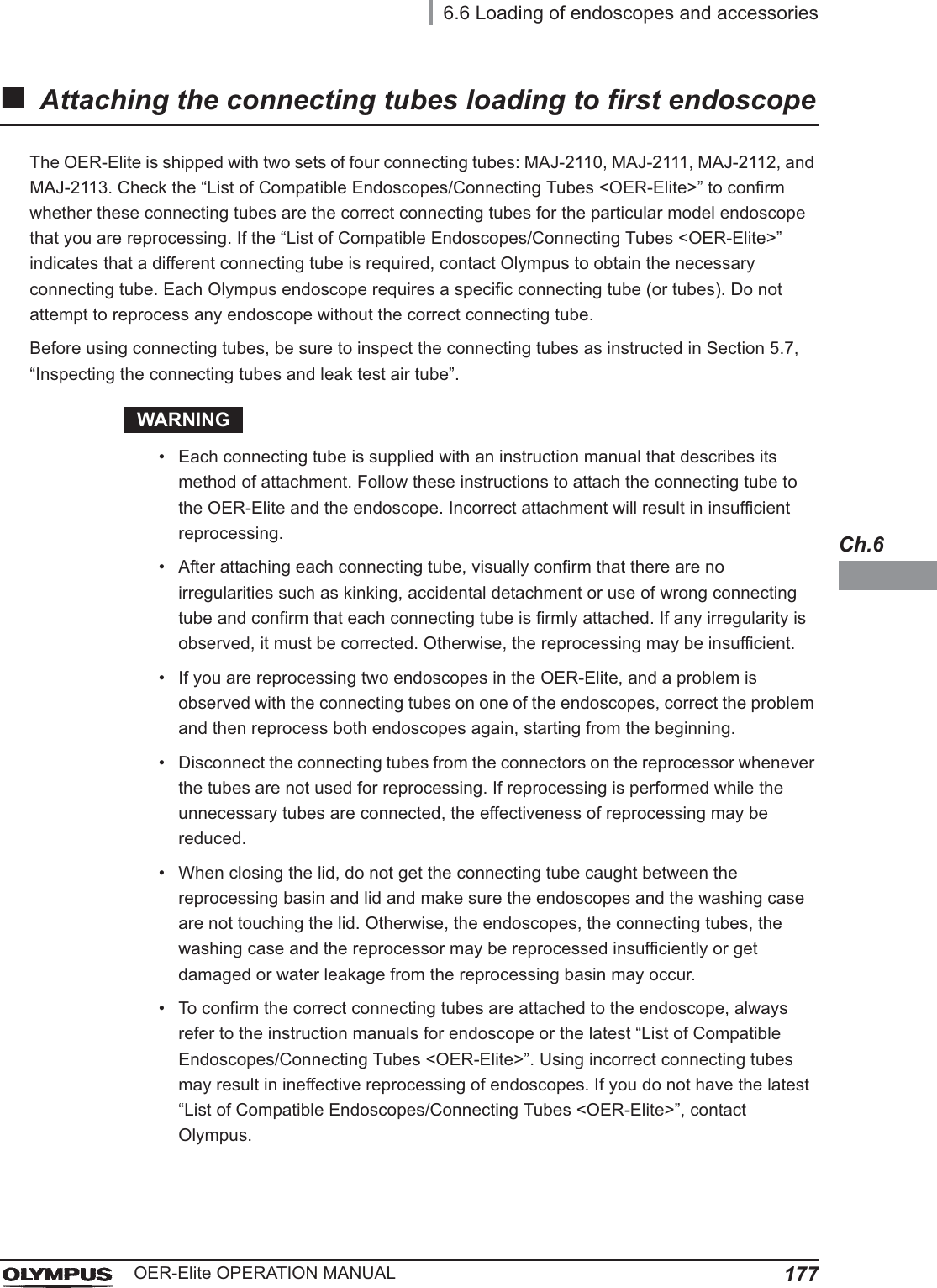
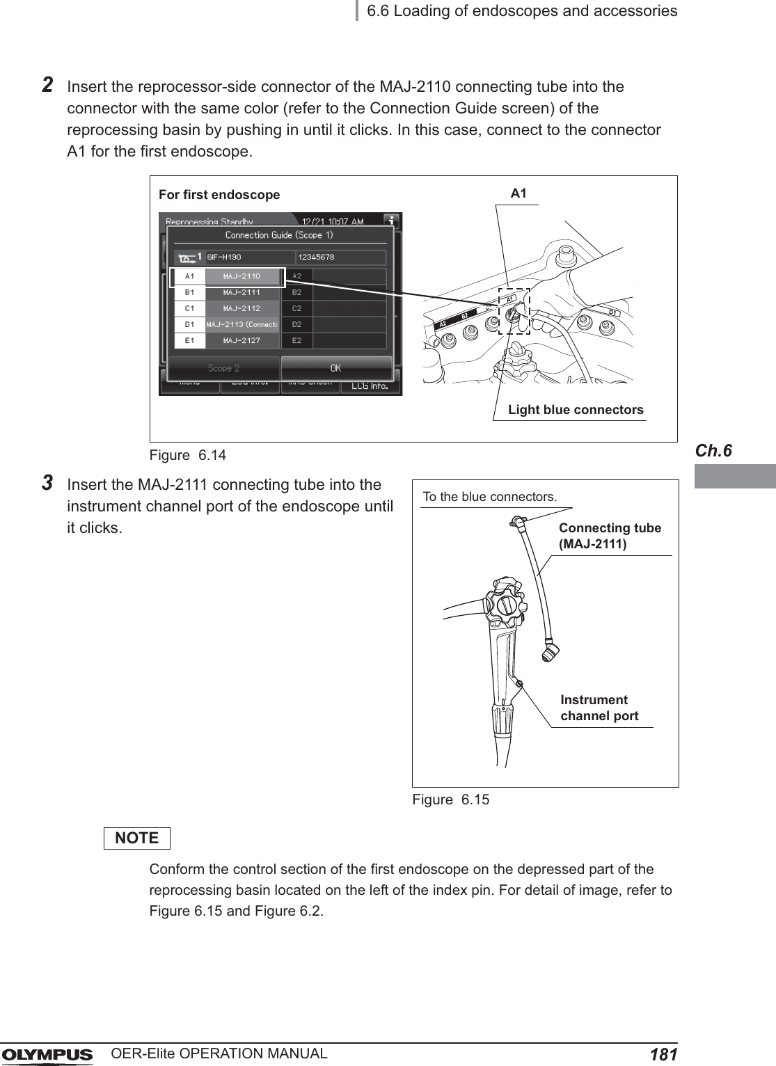
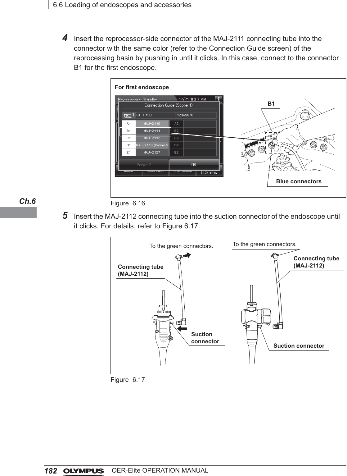
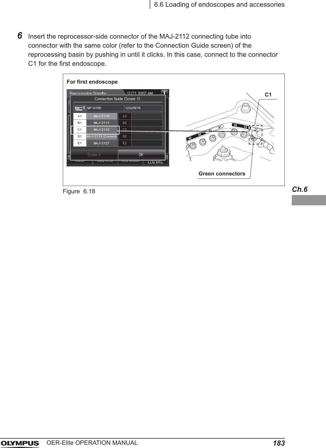
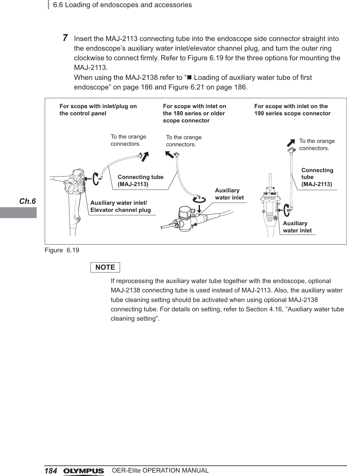
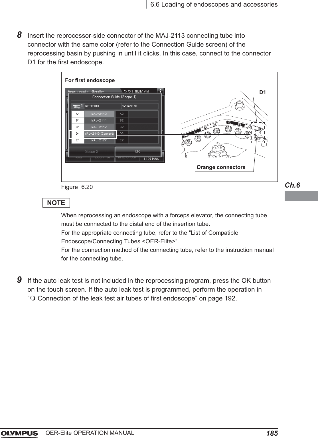
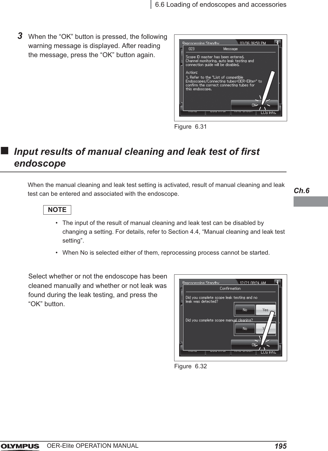
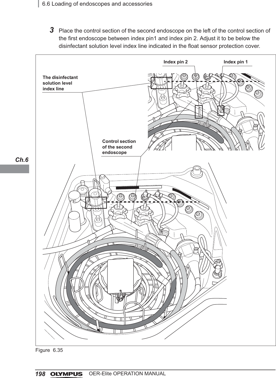
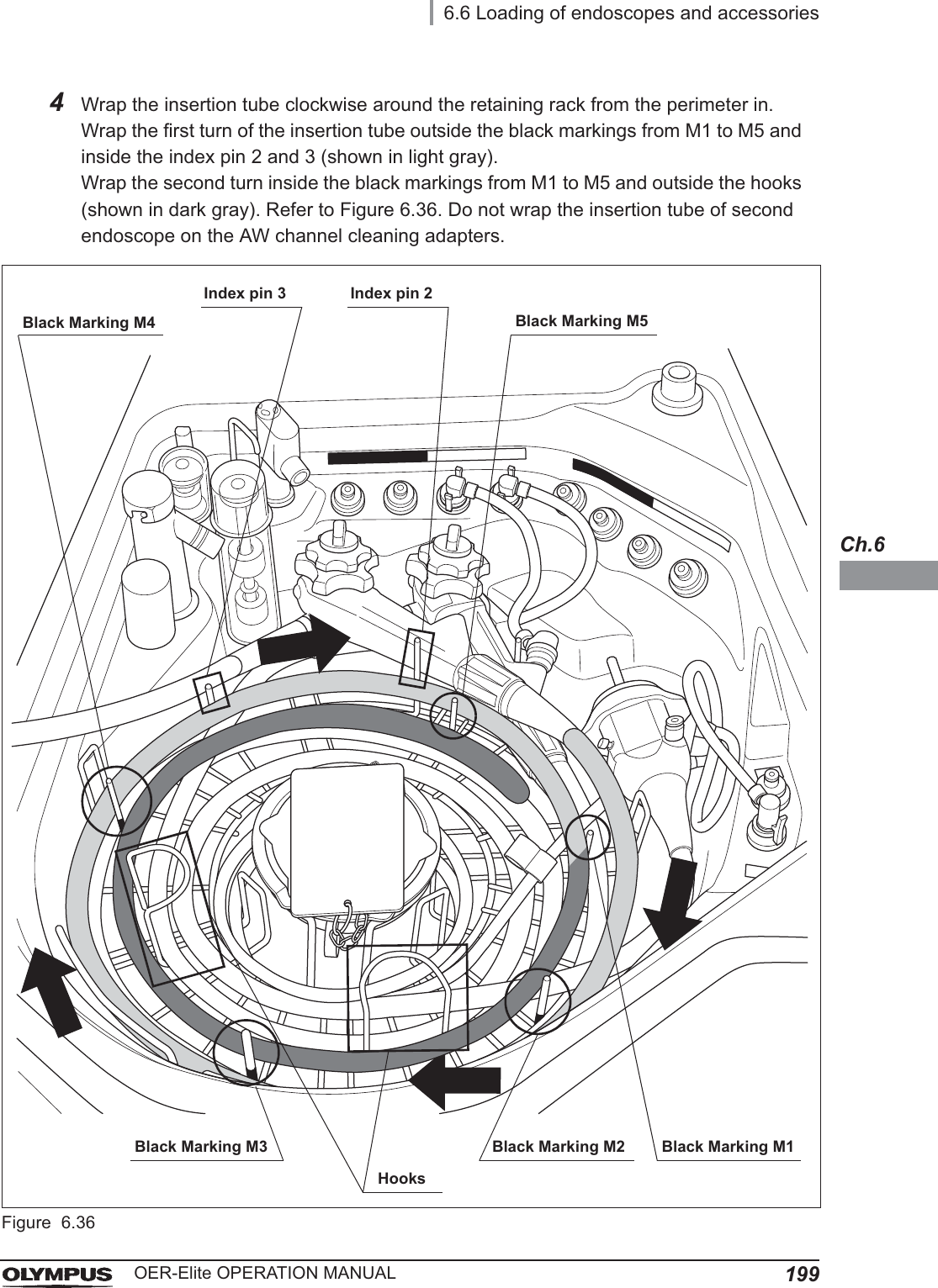
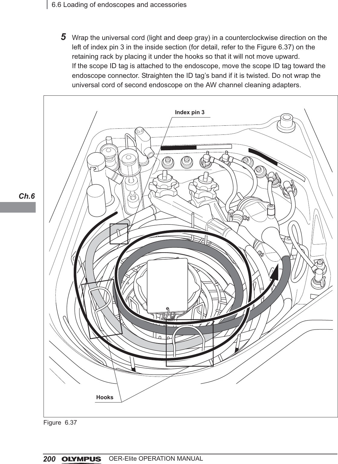
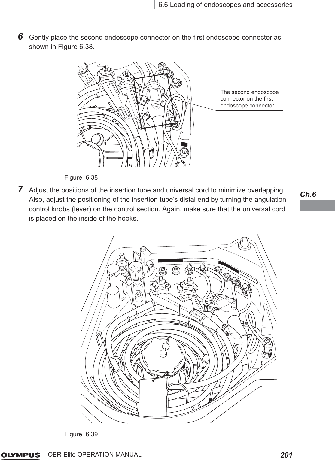
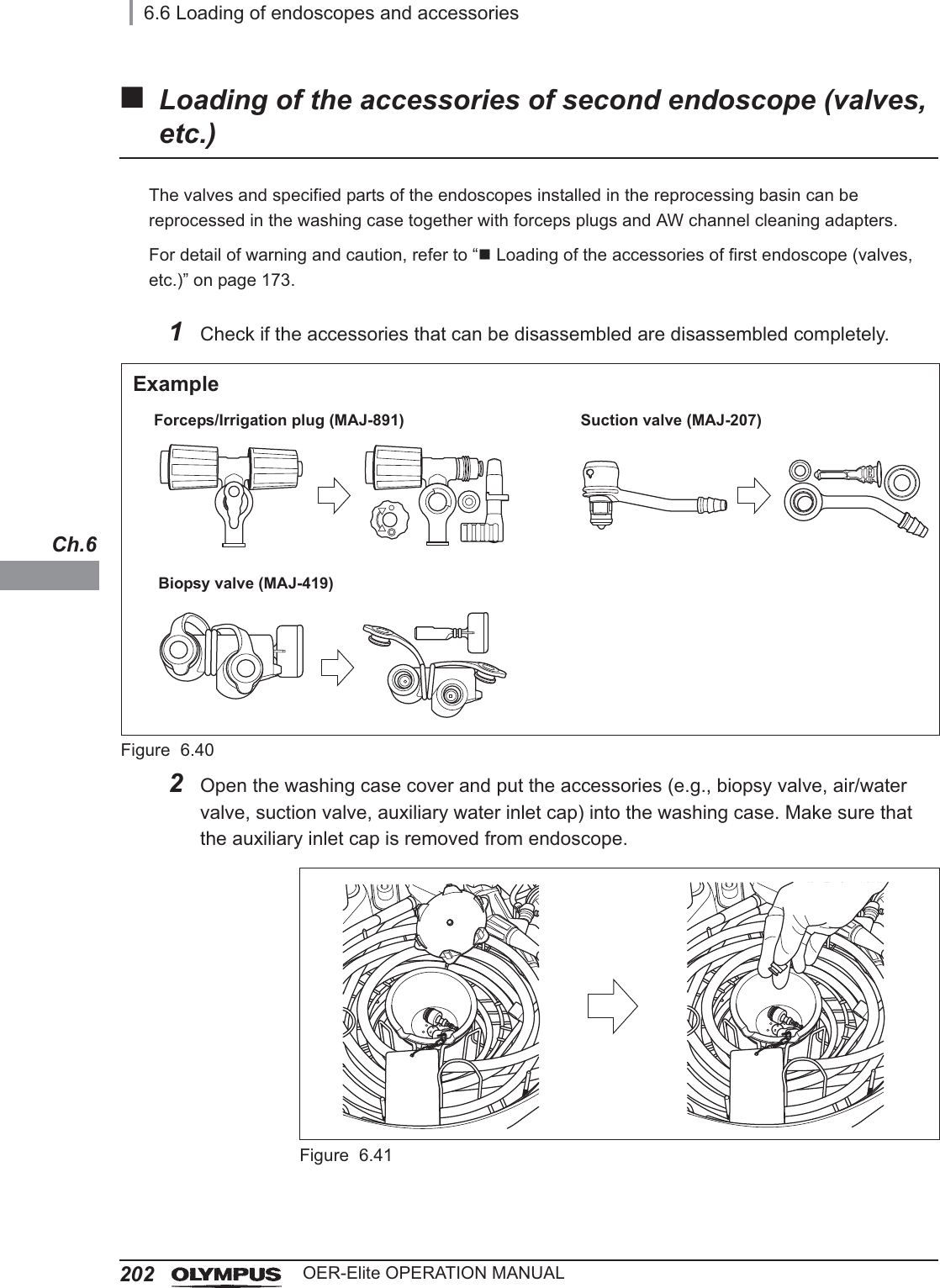
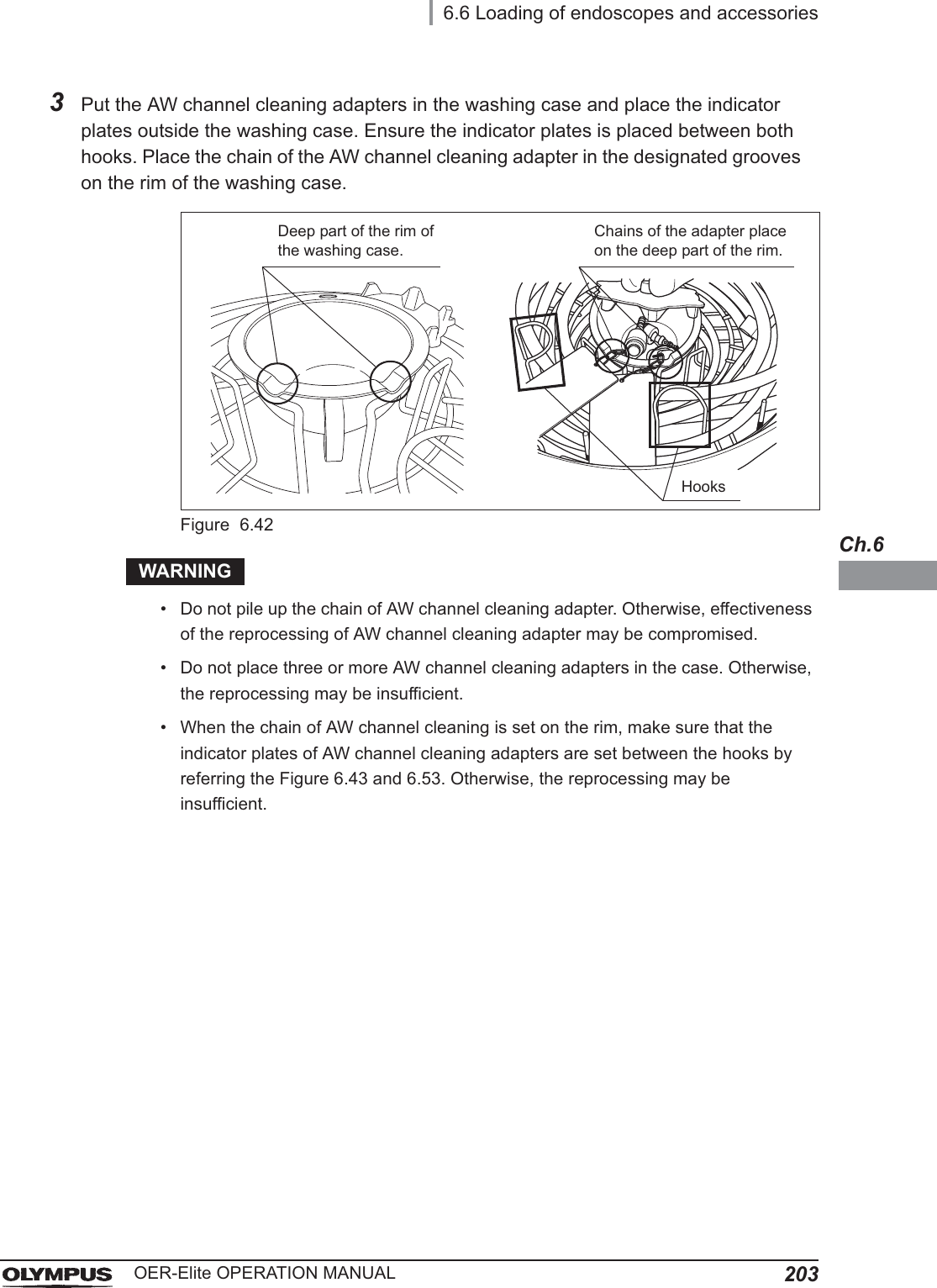
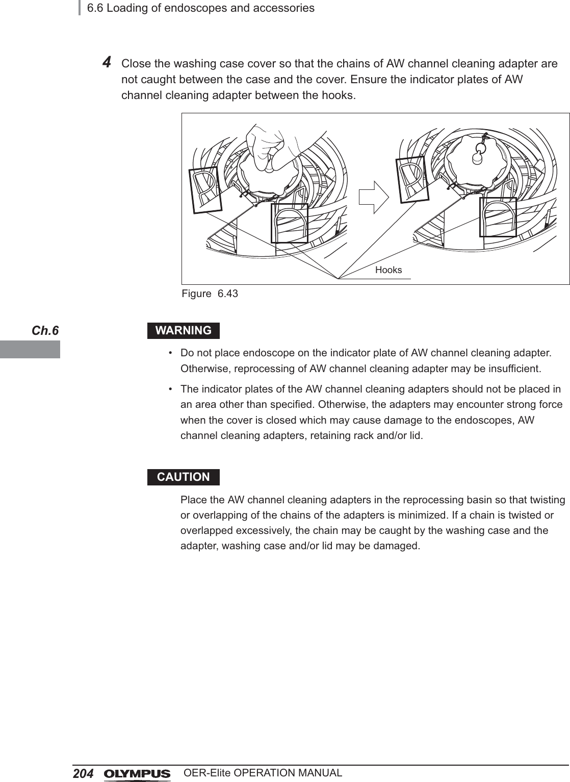
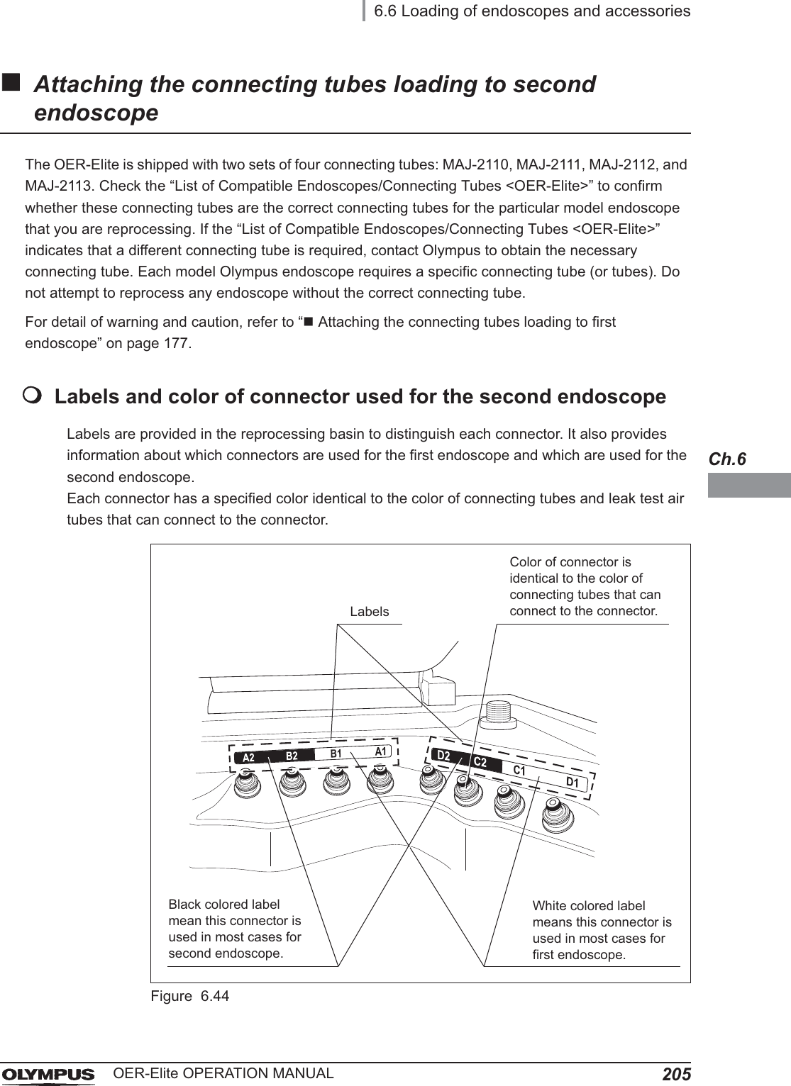
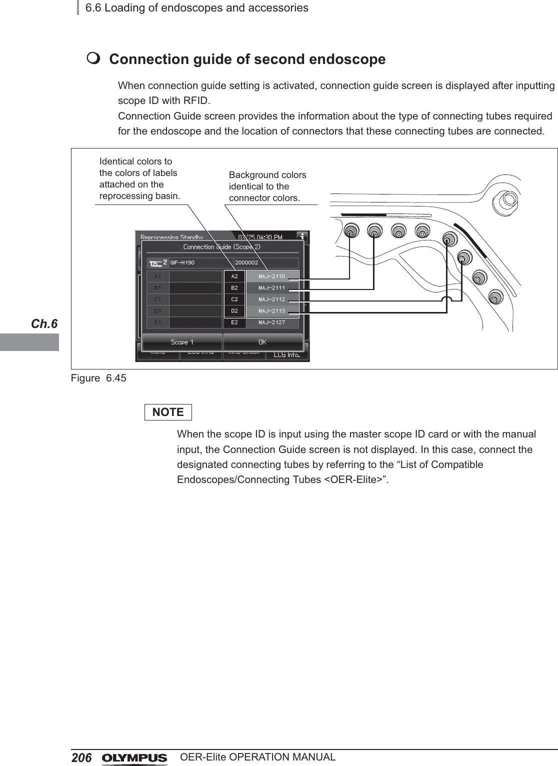
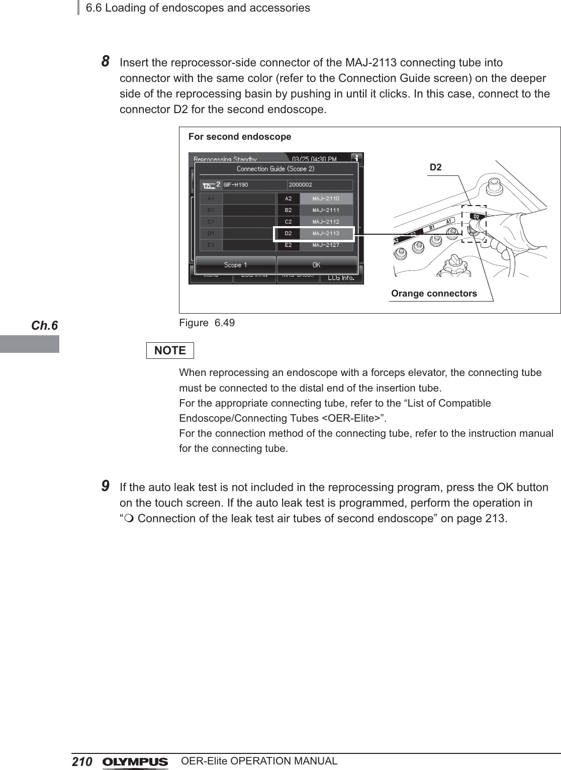
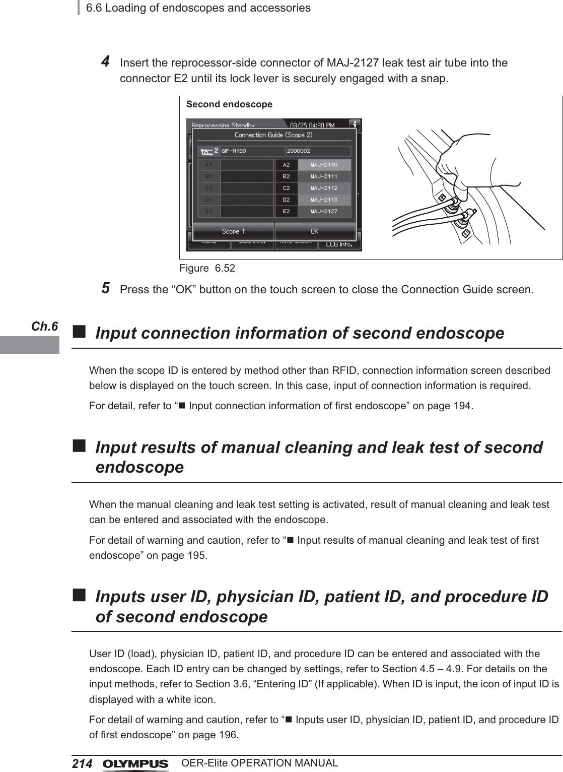
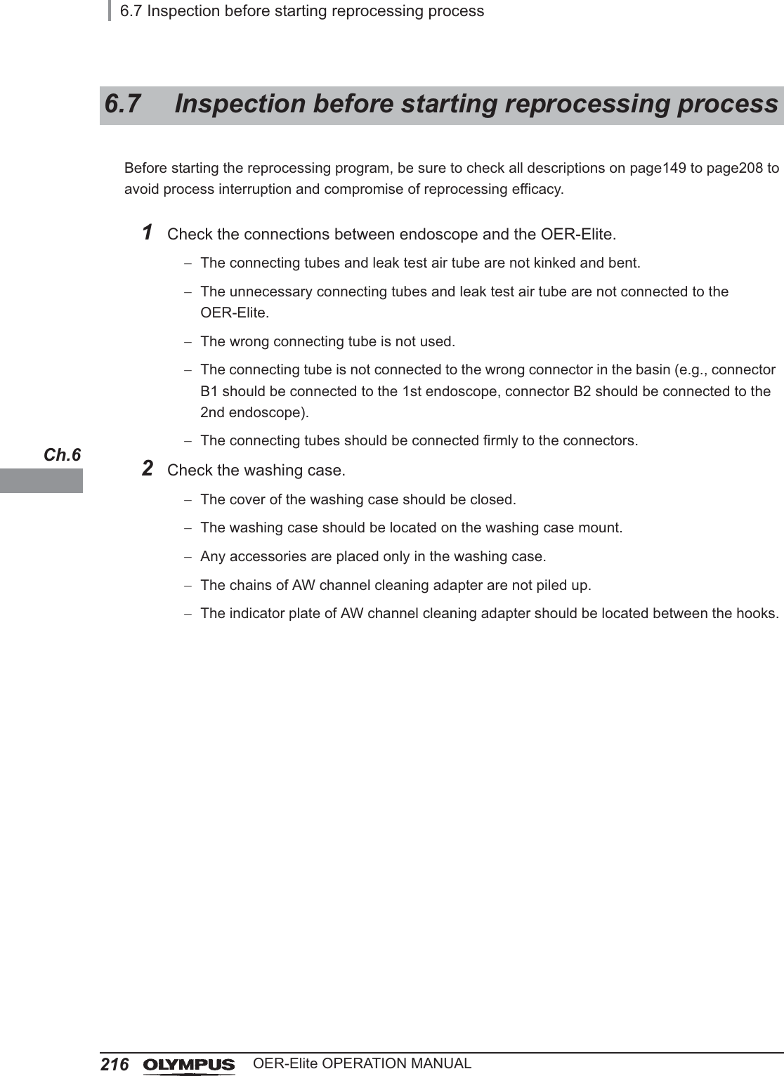
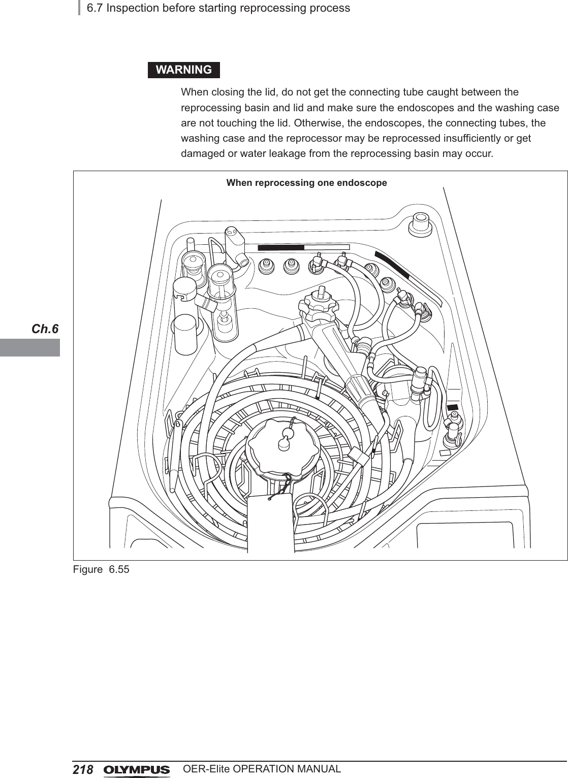
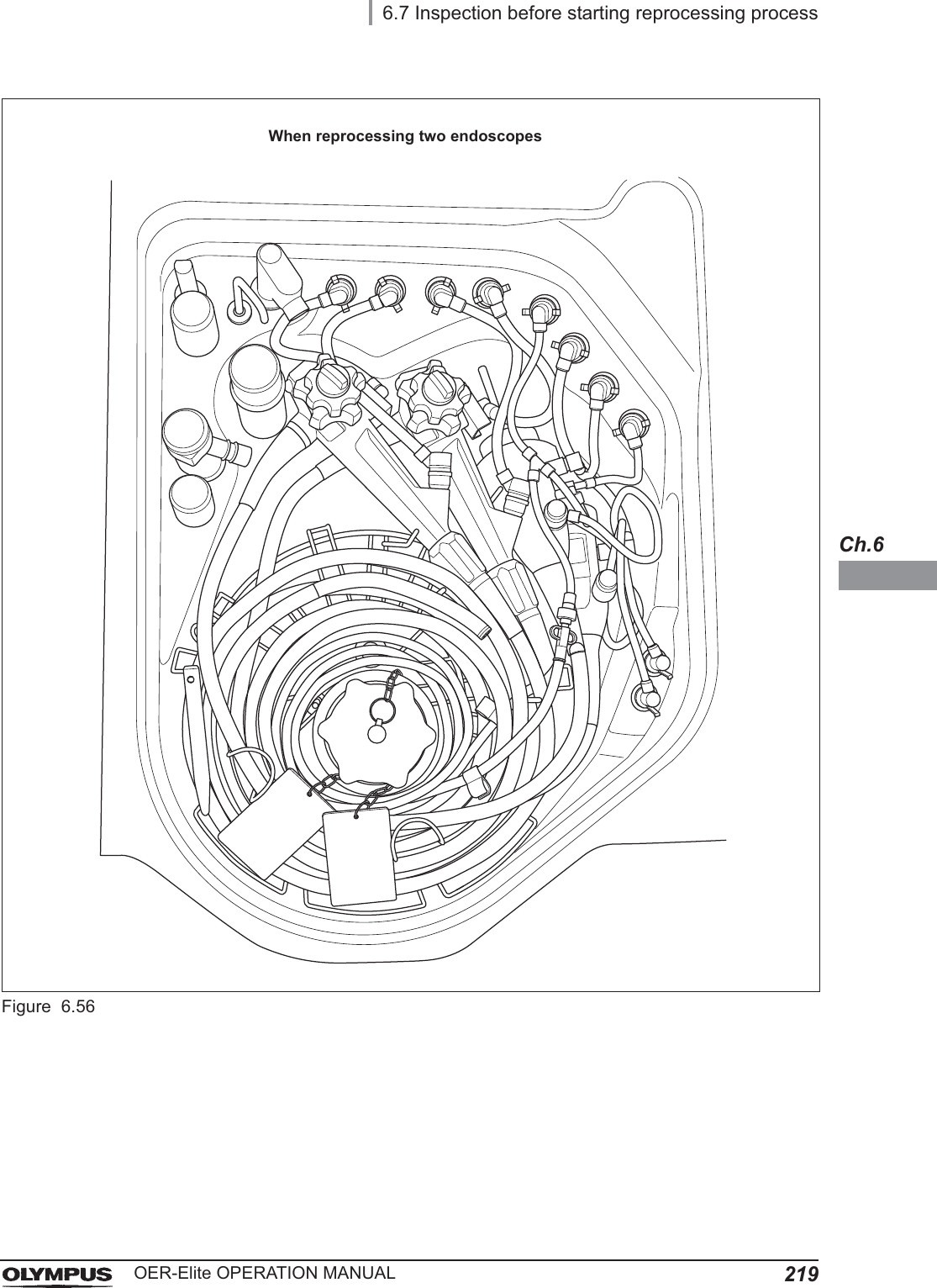
![6.6 Loading of endoscopes and accessories167OER-Elite OPERATION MANUALCh.6WARNING• Before starting the reprocessing cycle, be sure to confirm that the endoscopes are installed below the disinfectant solution level index line on the cover of float switch (long) and the cover of float switch (long) is attached firmly. If the endoscope is not fully submerged in the disinfectant solution, reprocessing may be insufficient.• When loading endoscopes, always be sure to disconnect cleaning accessories used for manual process from the endoscope. Otherwise, reprocessing may be insufficient.• Be sure to check that the whole of endoscope and accessories is installed below the disinfectant solution level index line on the cover of float switch (long). If the endoscope and accessories is installed above the disinfectant solution level index line, the reprocessing may be insufficient. Refer to Figure 6.37.CAUTION• When installing an endoscope that requires water-resistant cap, attach water-resistant cap by following the instructions for the endoscope. If a cap is not attached or a cap with moisture inside is attached, the endoscope will fail or malfunction.• Ensure that each endoscope is free of noticeable damage before placing it in this reprocessor. Otherwise, fluid leak may occur during the reprocessing. If damage is noticed, perform the leaking scope decontamination and contact Olympus for servicing. For details on the leaking scope decontamination, refer to Section 7.15, “Leaking scope decontamination”.• Do not let the distal end of an endoscope drop from the retaining rack or contact the reprocessing basin directly. Otherwise, the endoscope may be damaged.• When the leak test air tube is not used, disconnect it from the connector and be sure to remove it from the reprocessing basin. If reprocessing is performed without removing it, water or disinfectant solution may enter inside the tube and may cause a failure of the tube. Also, if the water or disinfectant solution entering the leak test air tube during the scope leak test enters inside the endoscope, endoscope failure may result.• When reprocessing is started without disconnecting the unused leak test air tube(s), error code [E024] is generated and the process stops. For detail on this error code, refer to “When the error code [E024] is displayed during the reprocessing process” on page 614.• When reprocessing endoscopes, always be sure to attach the retaining rack in the reprocessing basin. Otherwise, external surface of endoscopes may contact the heating portion of the reprocessing basin, resulting in possible damage to endoscopes.](https://usermanual.wiki/Olympus-Medical-Systems/RU2020.Operation-Manual-2/User-Guide-3575673-Page-39.png)
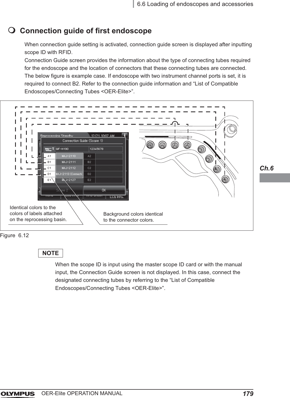
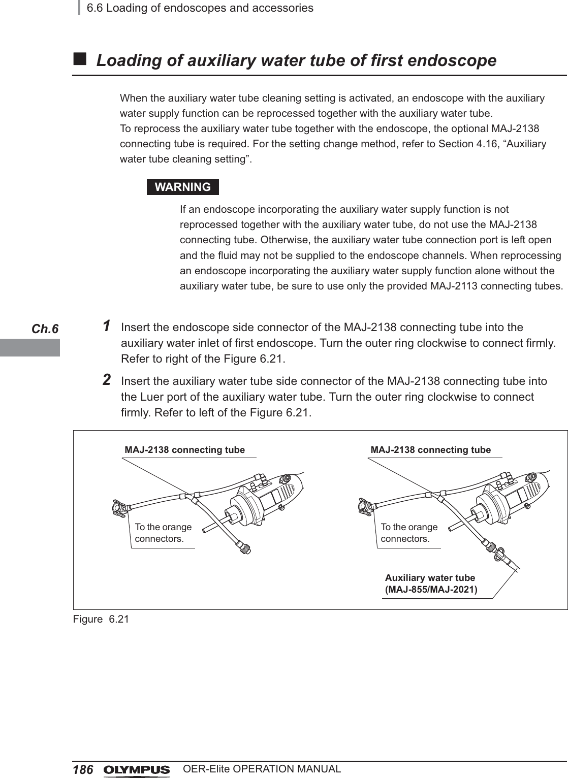
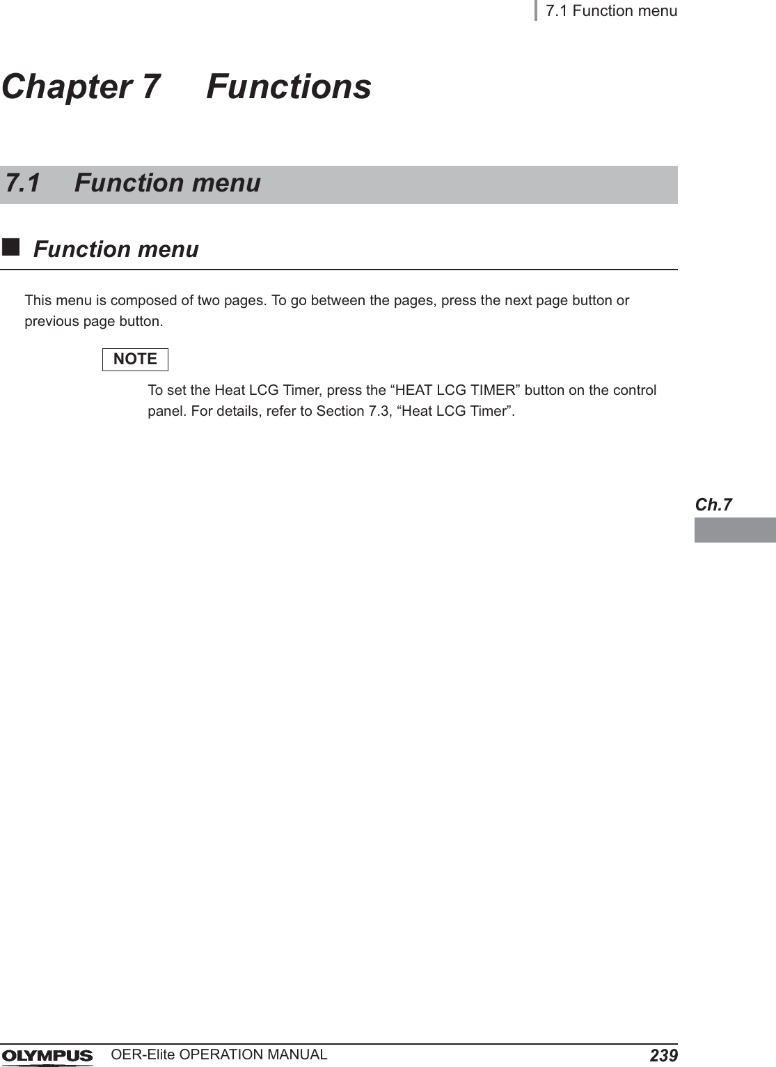
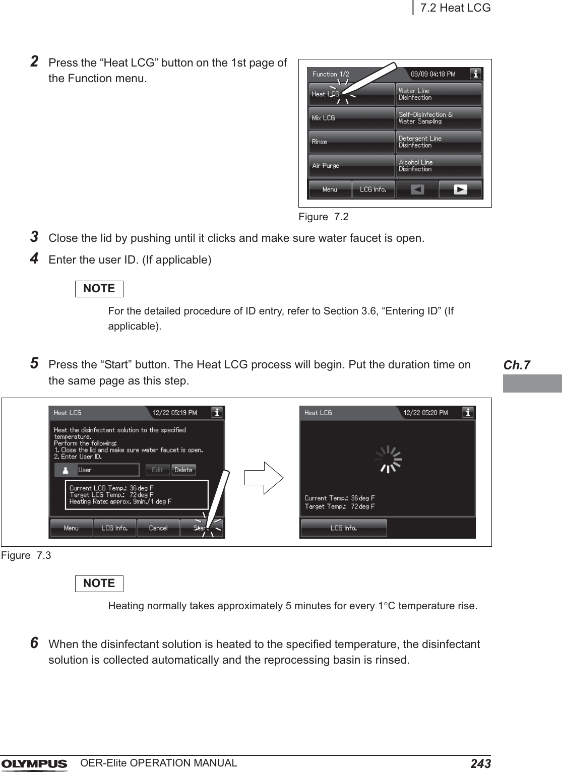
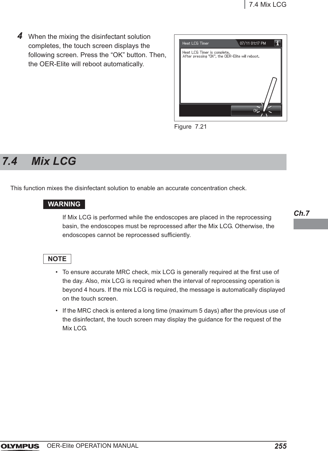
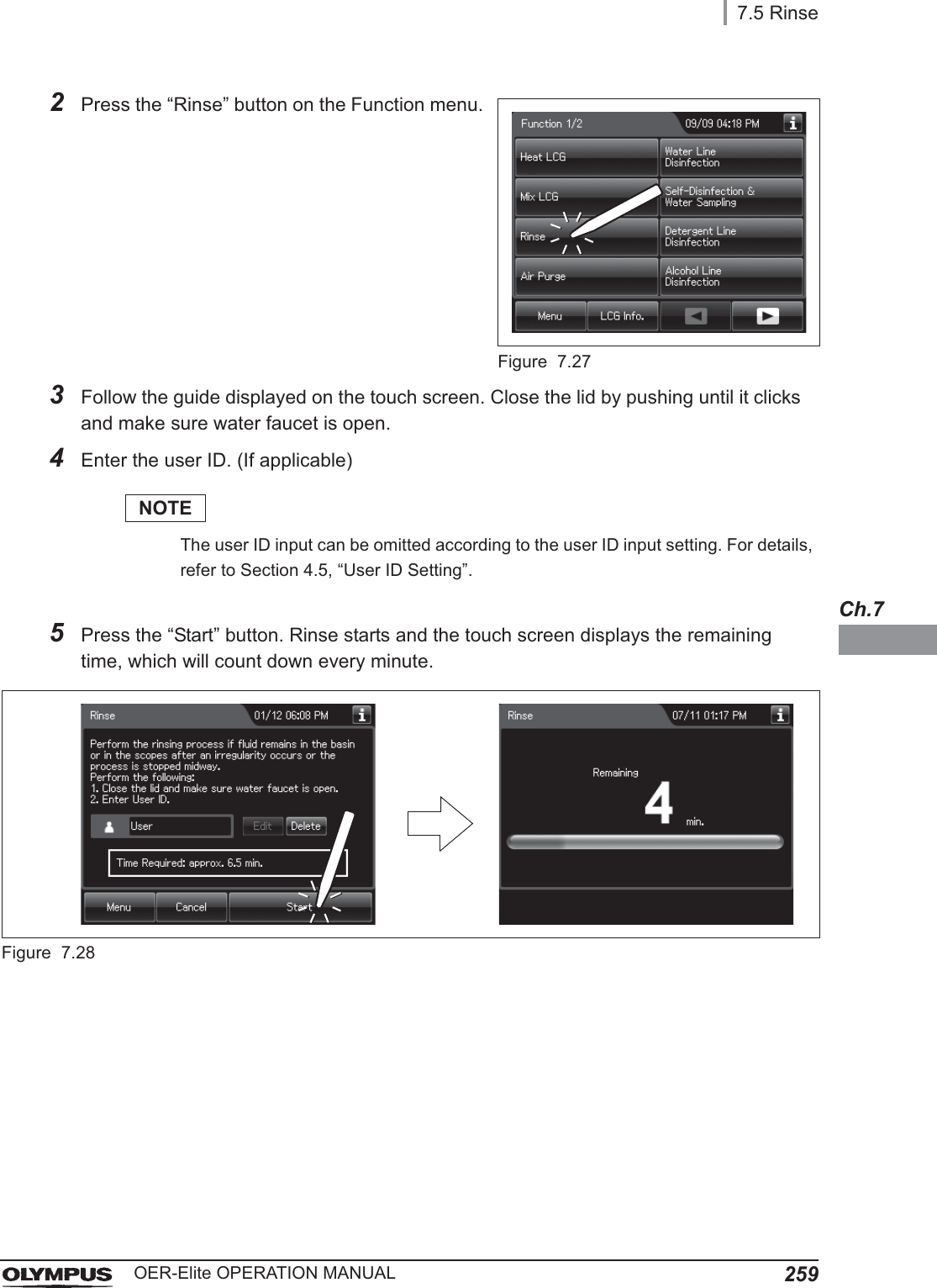
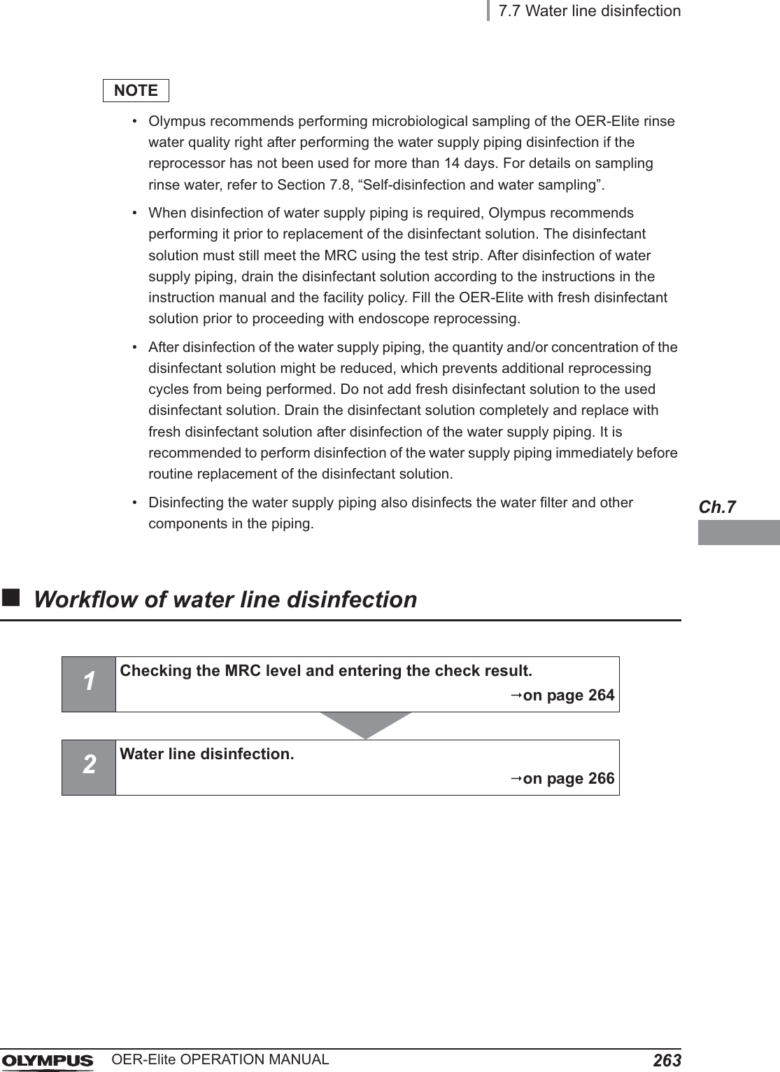
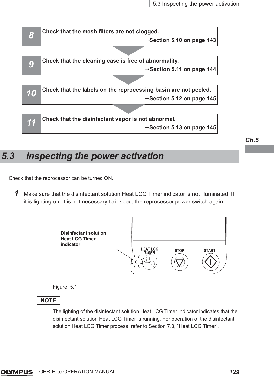
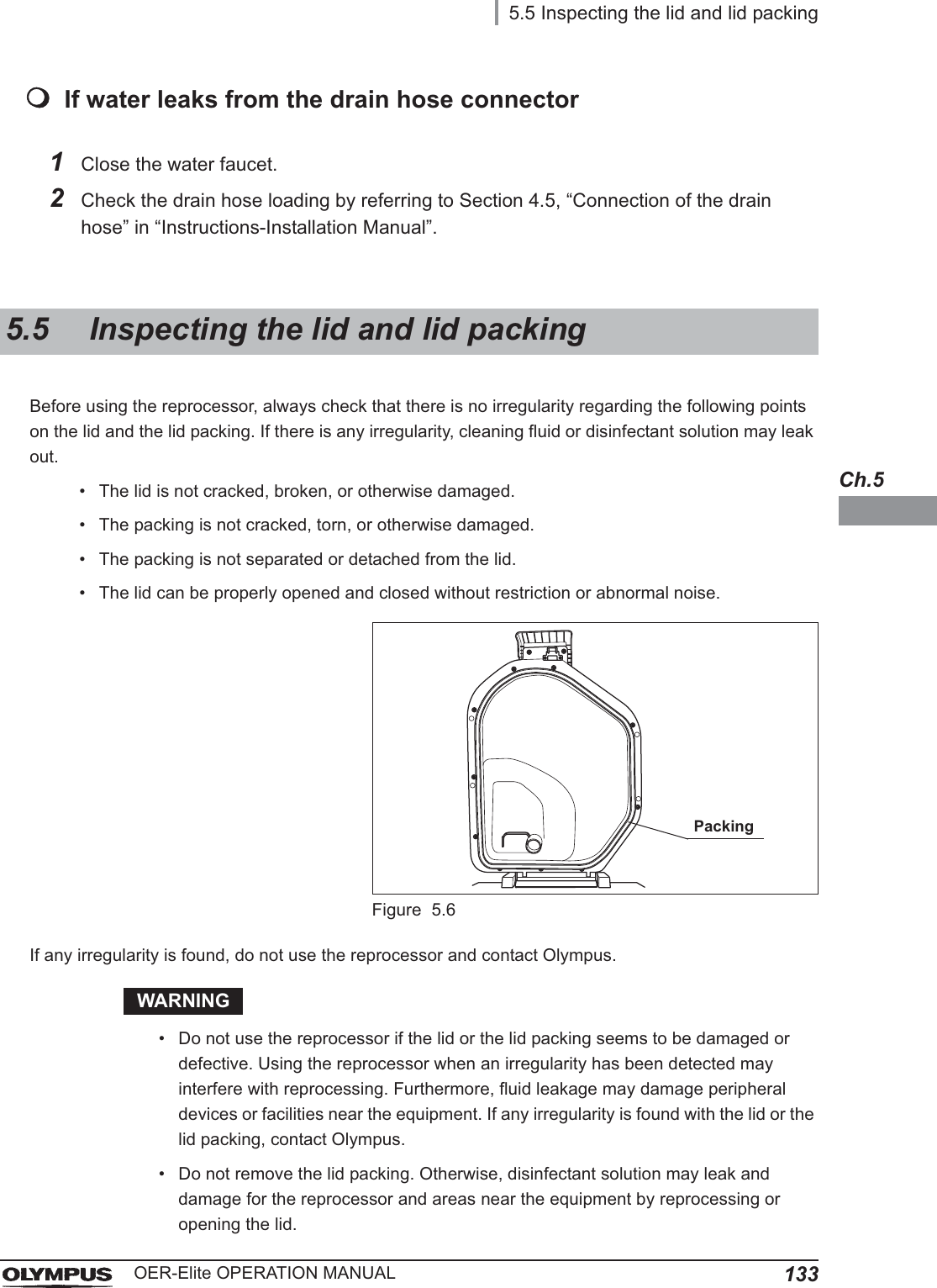
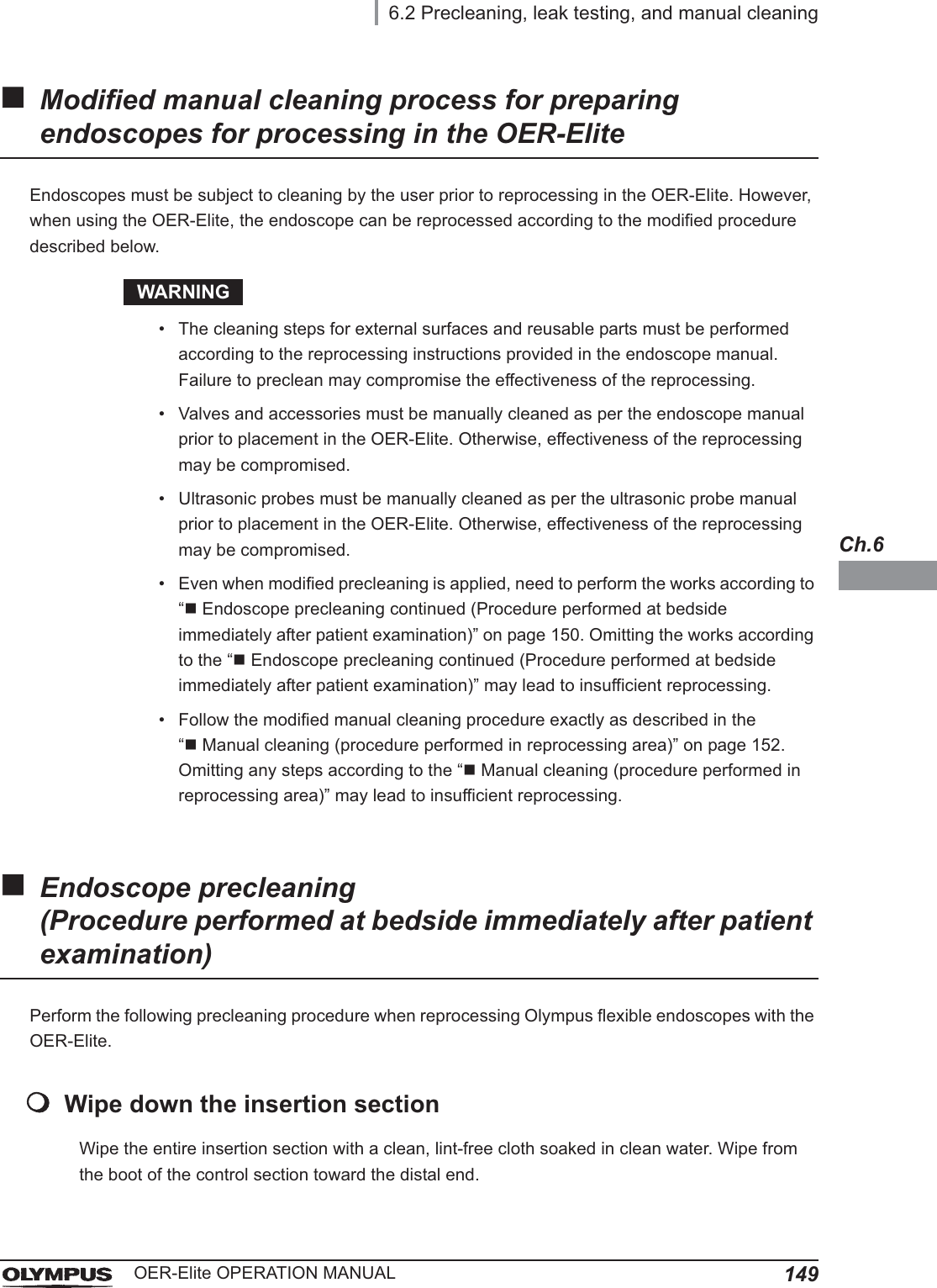
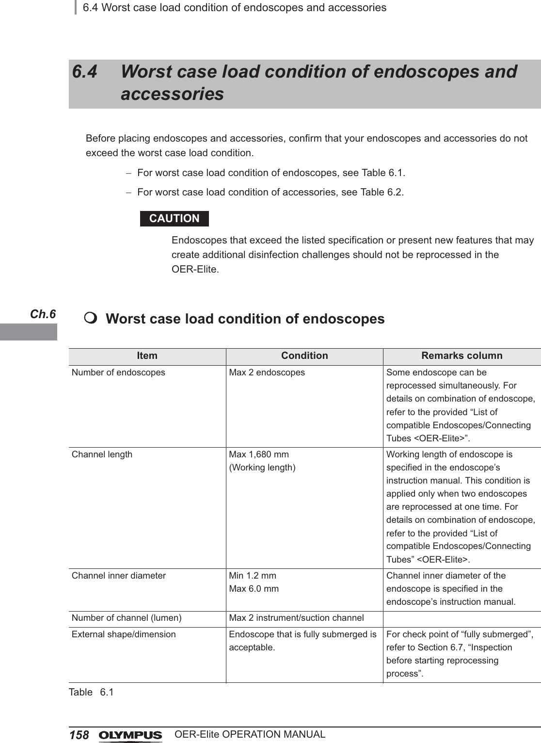
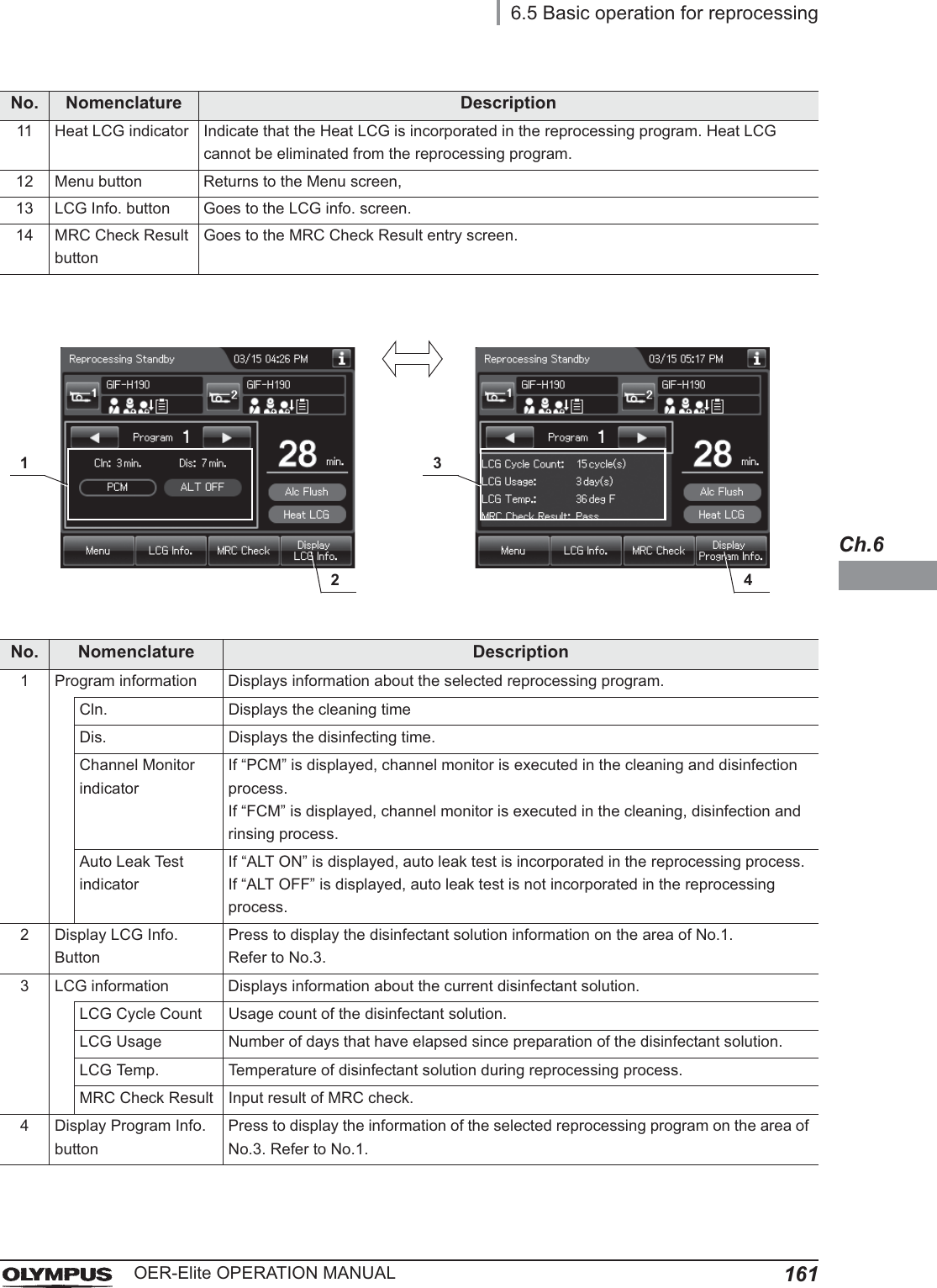
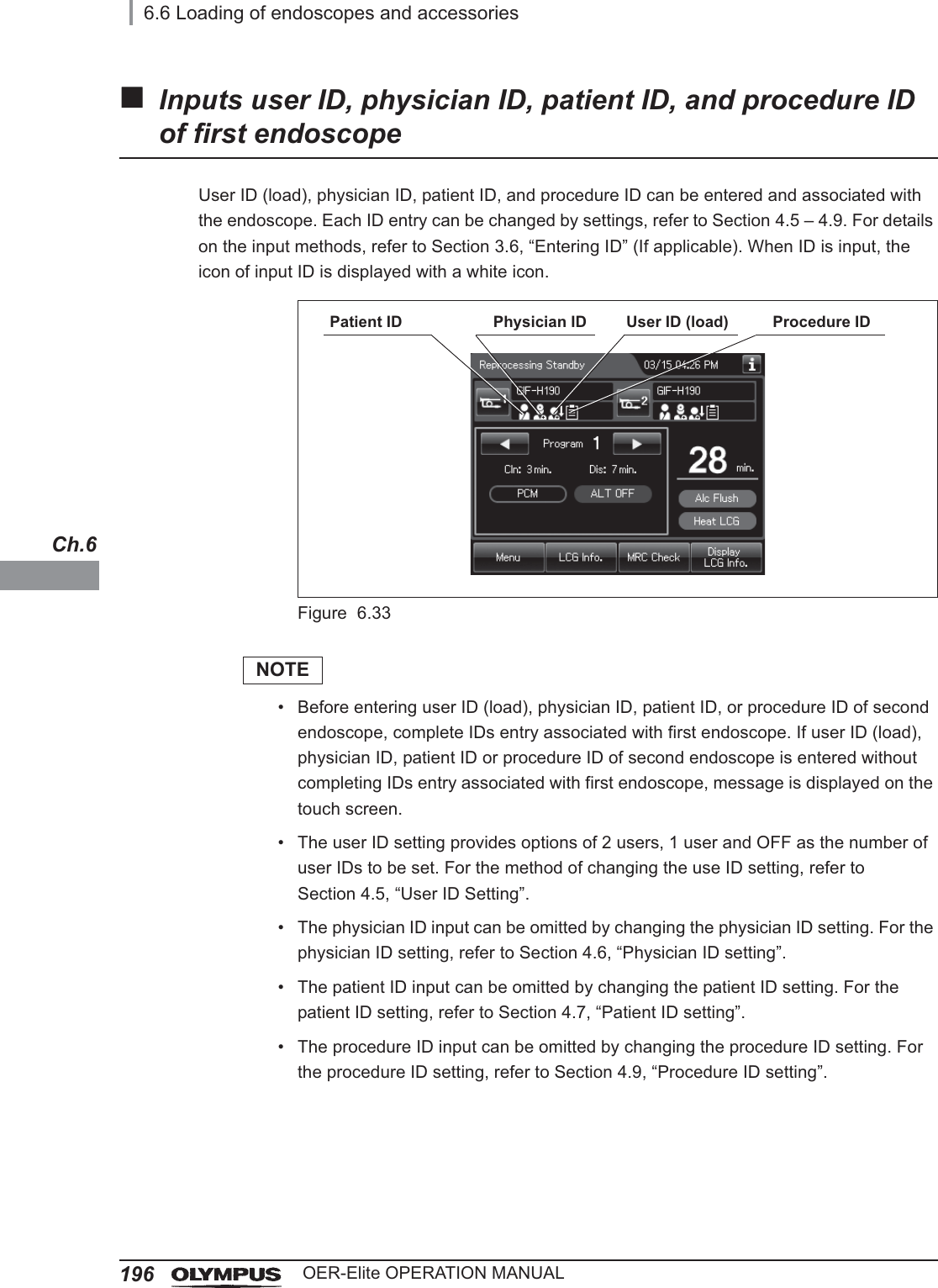
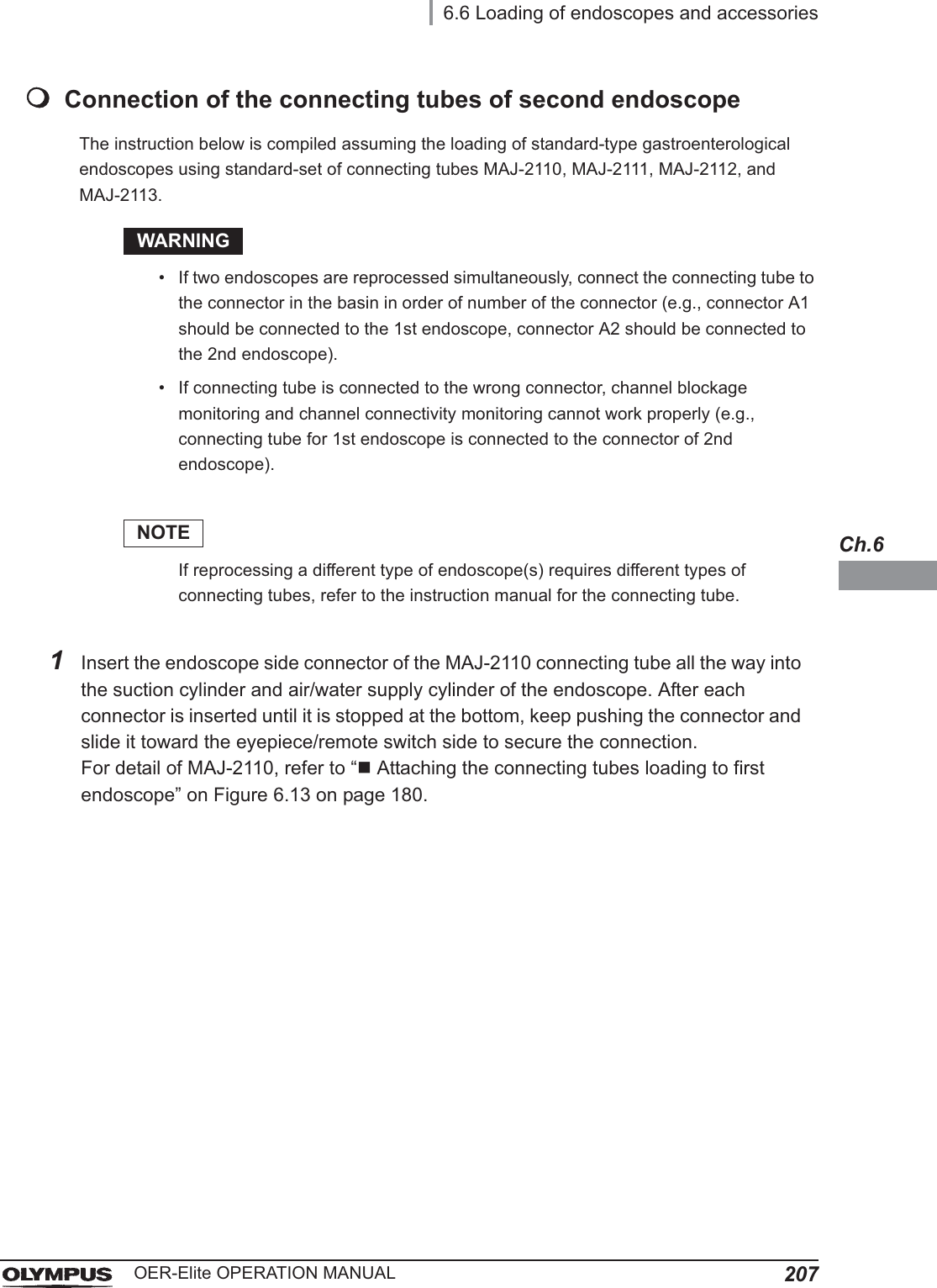
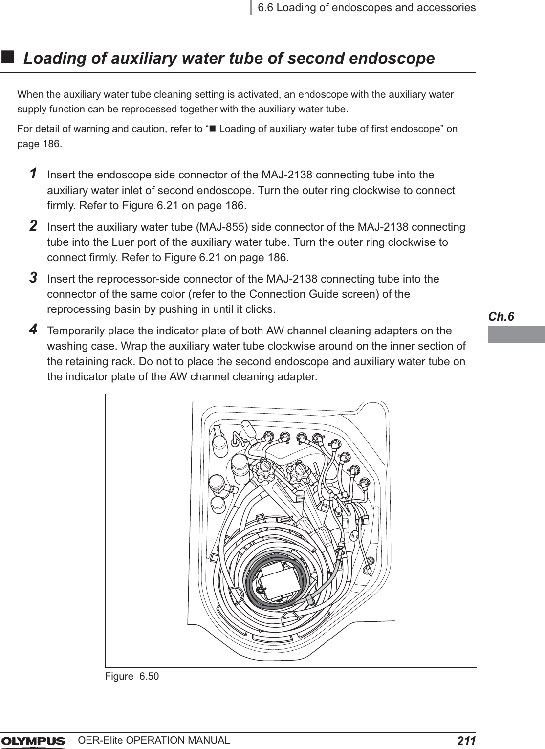
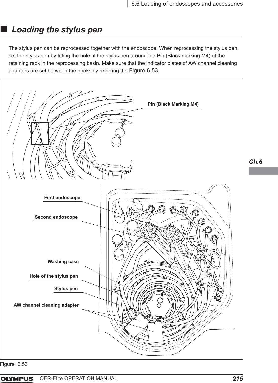
![1946.6 Loading of endoscopes and accessoriesOER-Elite OPERATION MANUALCh.6Input connection information of first endoscopeWhen the scope ID is entered by method other than RFID, connection information screen described below is displayed on the touch screen. In this case, input of connection information is required.NOTEAccording to the input of connection information, the OER-Elite monitors the channel flow to check the internal valves are properly operated. This function does not support the detection of channel blockage and disconnection of connecting tube of endoscope side.1On the Connection information screen, press the “No Connection” buttons corresponding to the reprocessing basin connectors to which the connecting tubes are connected. The “No Connection” indicator will now change to “Connection”.Figure 6.29NOTEIf status other than the actual connecting tube connection status is selected, error code [E024] is generated during reprocessing and the reprocessing process stops.2Press the “OK” button.Figure 6.30Each press of either button alternates the displayed button name between “Connection” and “No Connection”.](https://usermanual.wiki/Olympus-Medical-Systems/RU2020.Operation-Manual-2/User-Guide-3575673-Page-66.png)
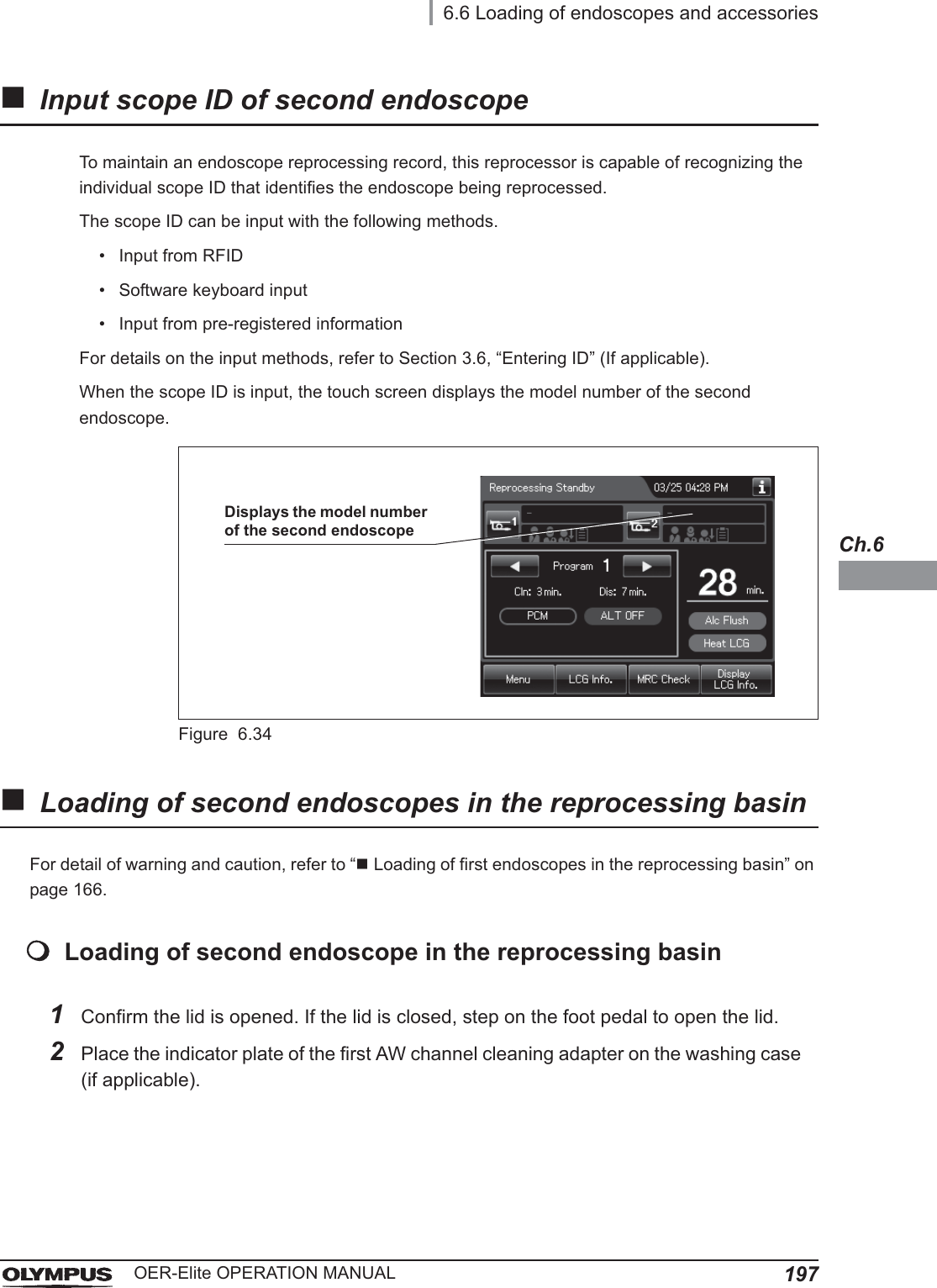
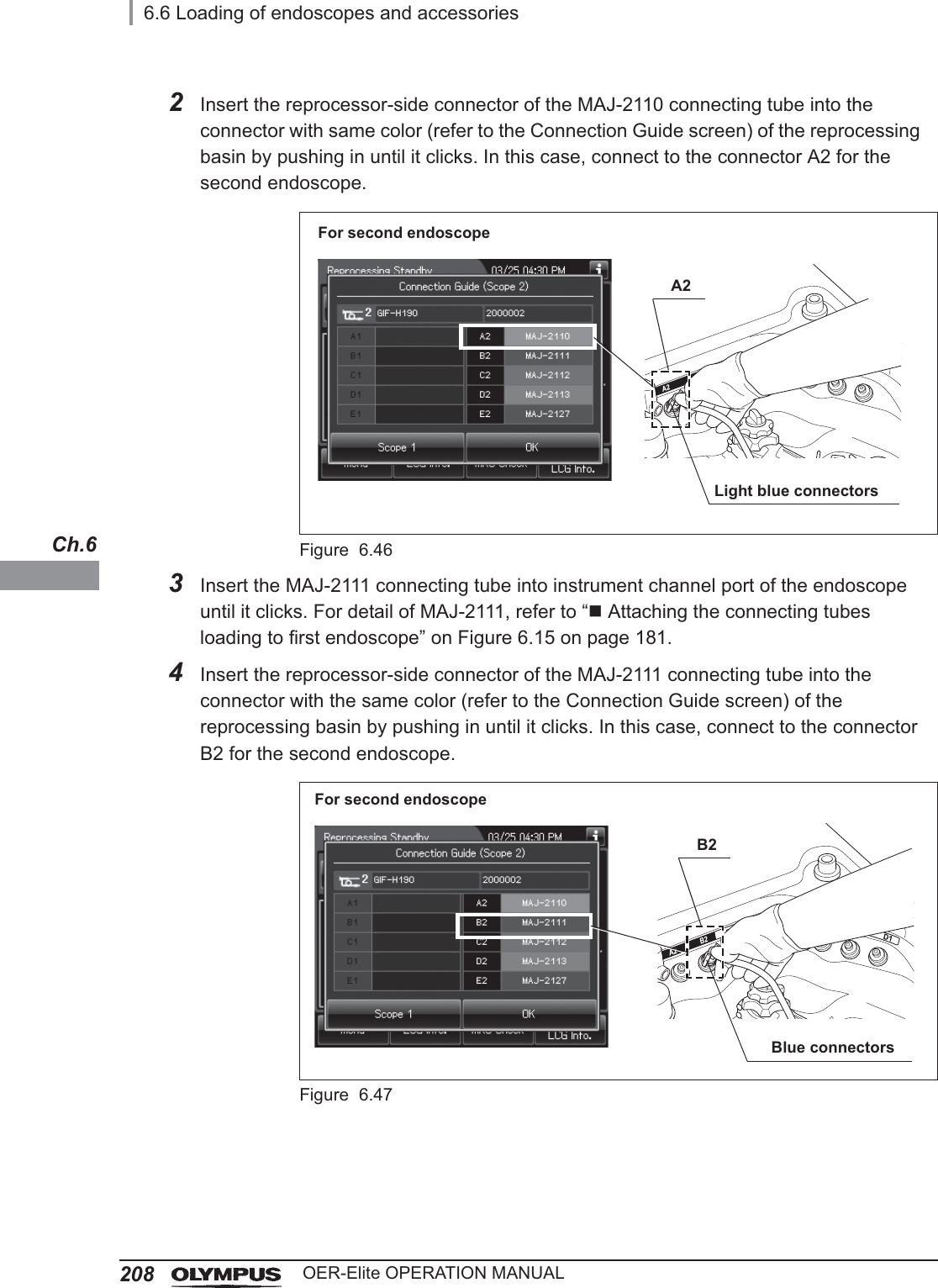
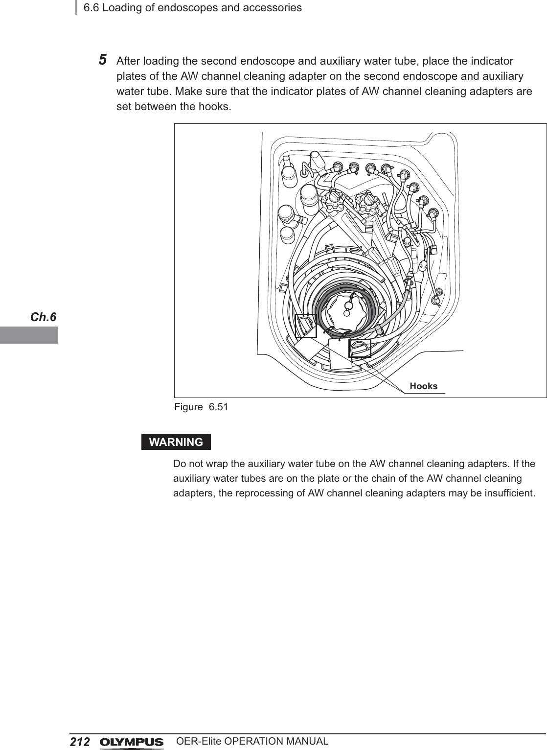
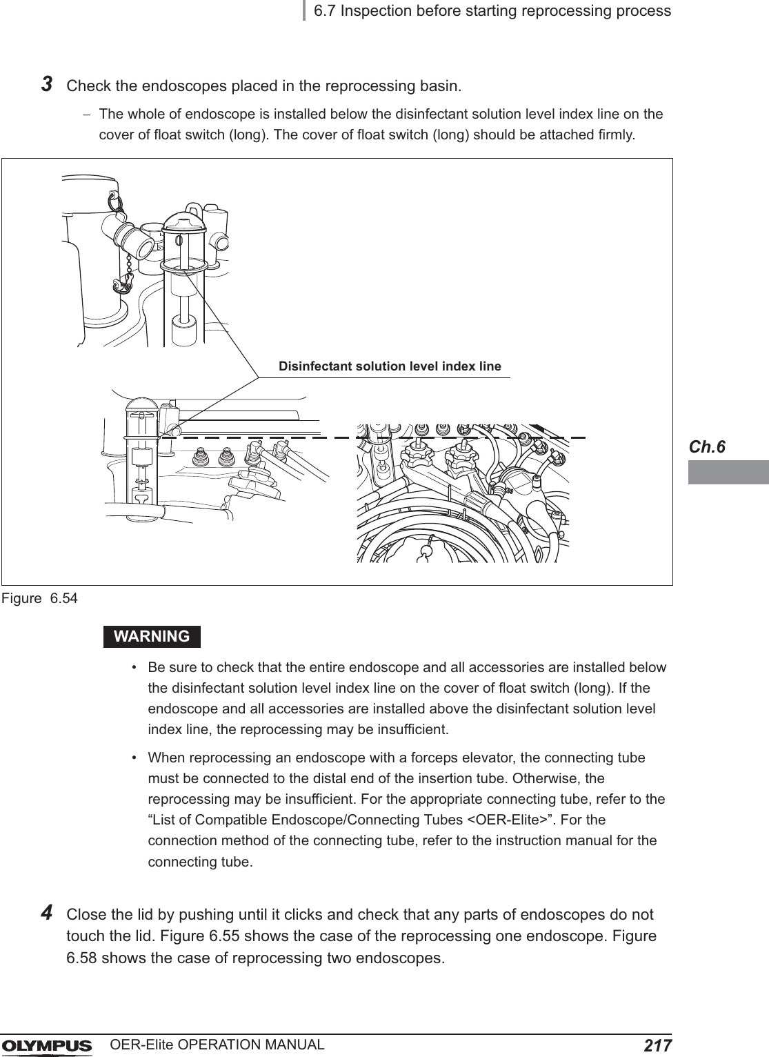
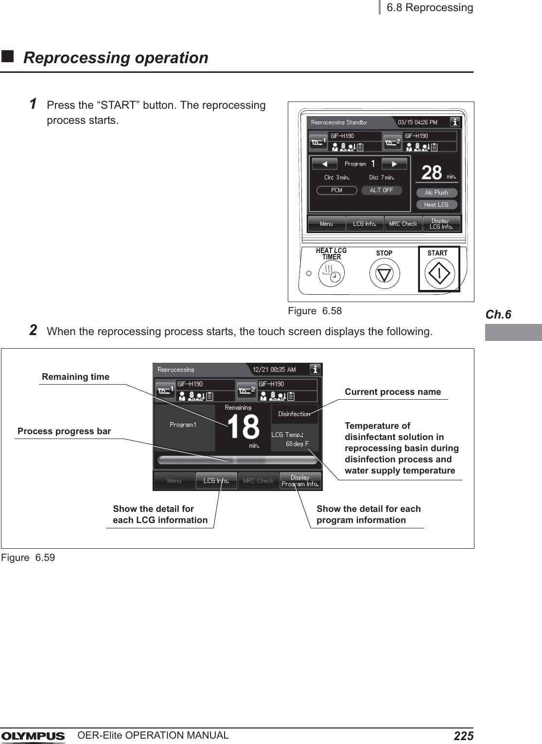
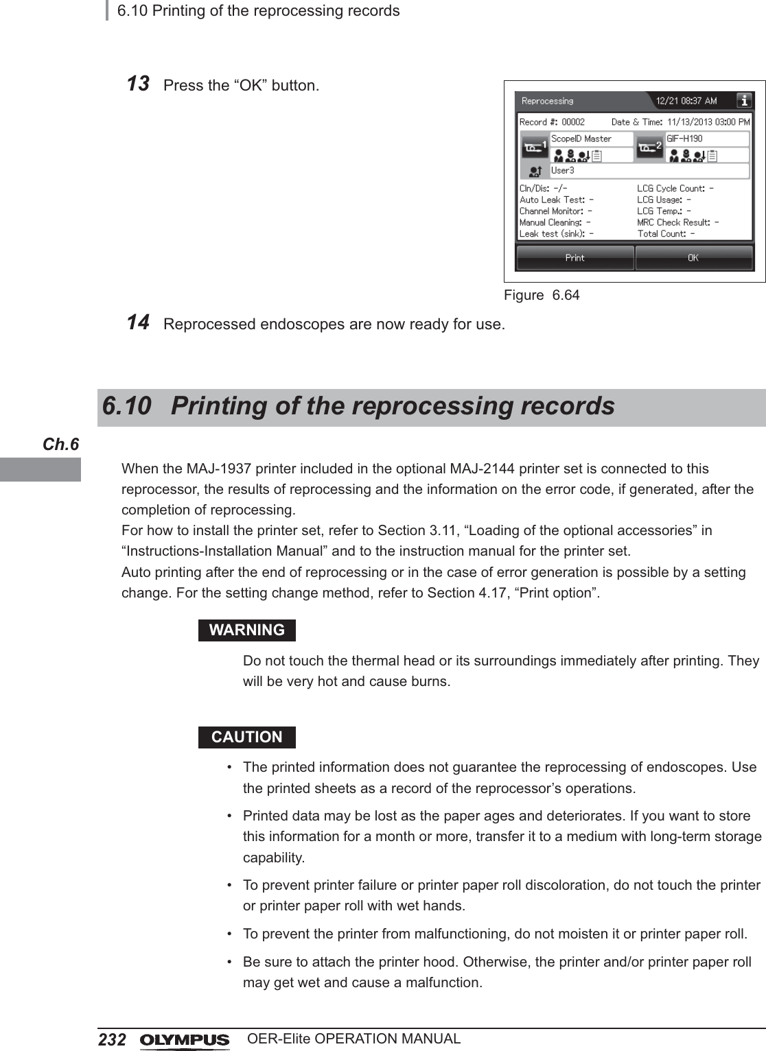
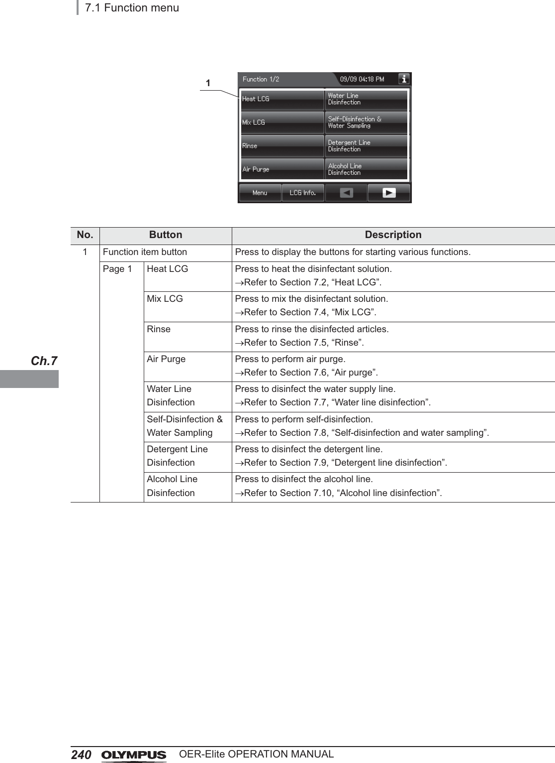
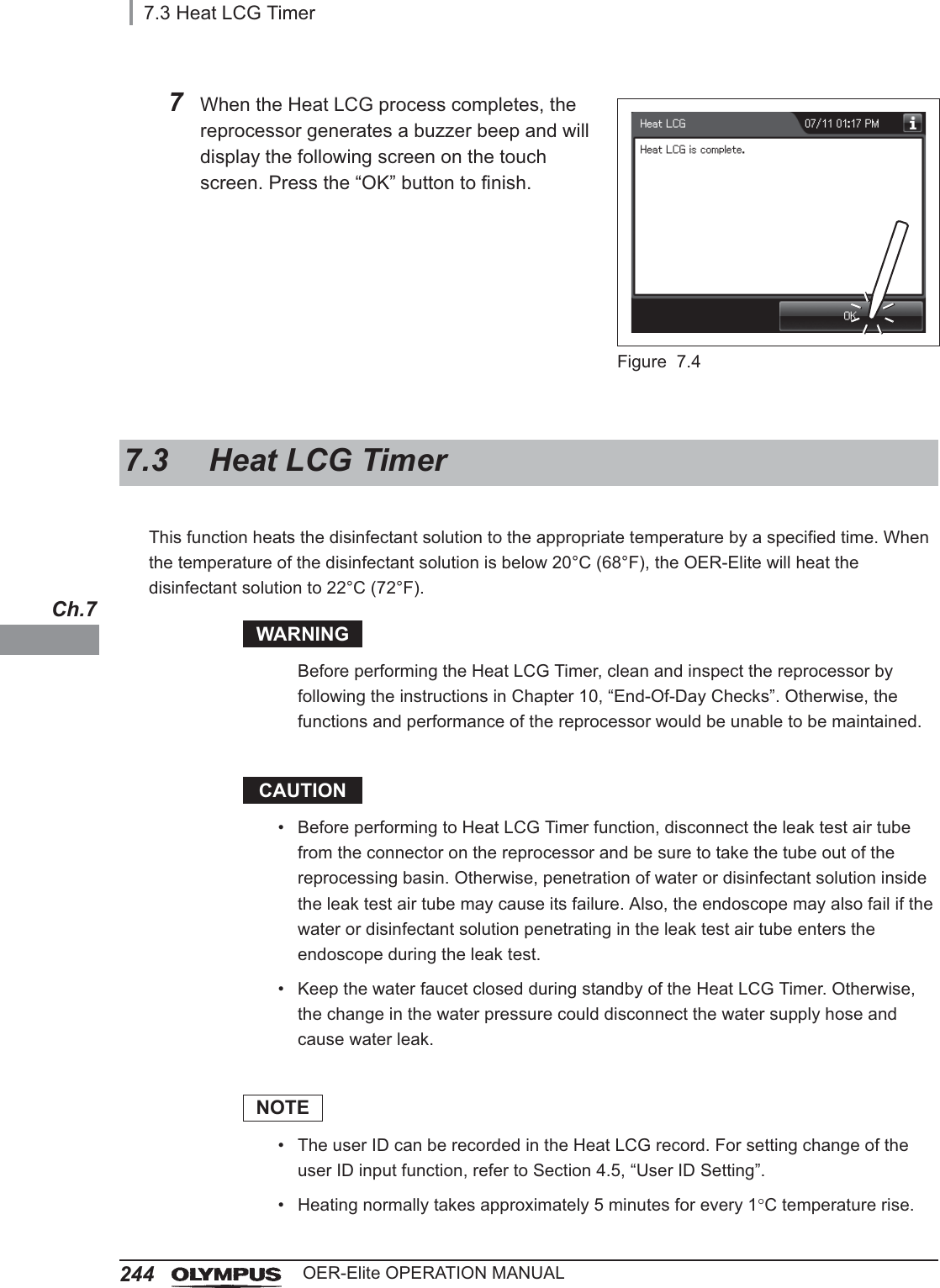
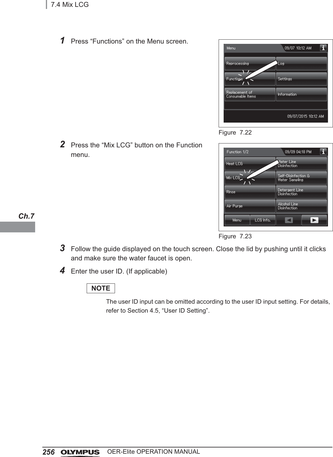
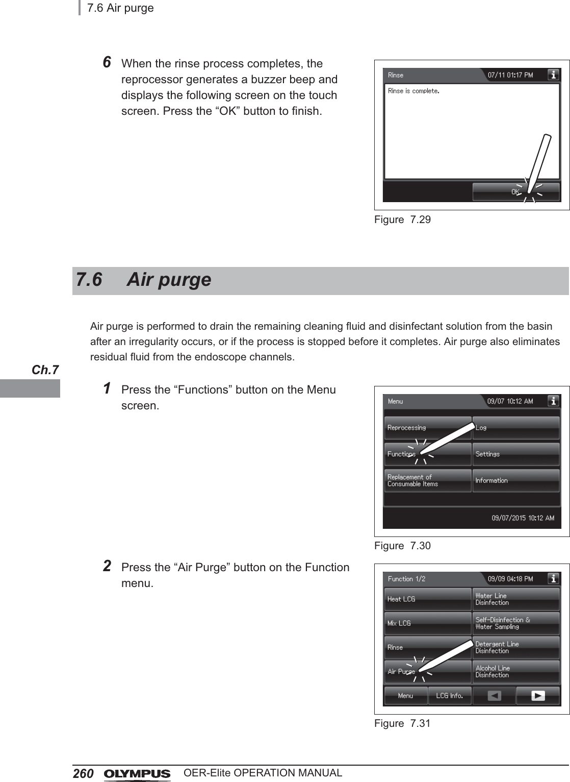
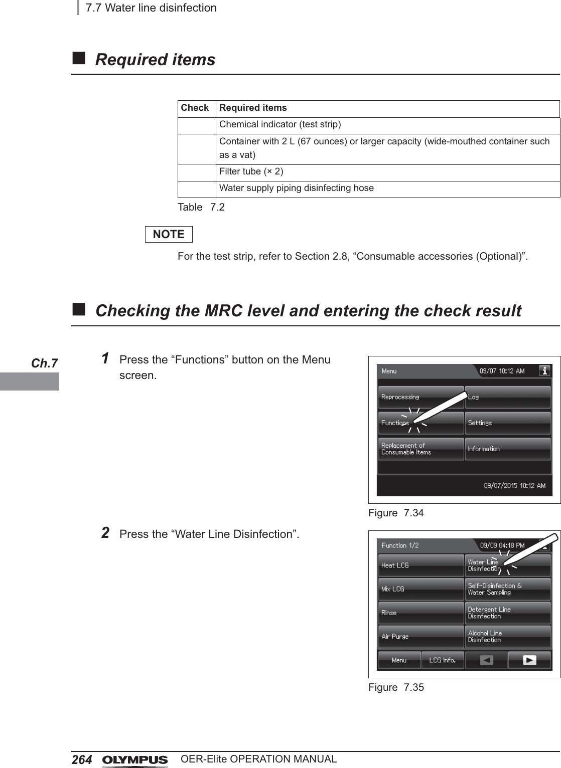
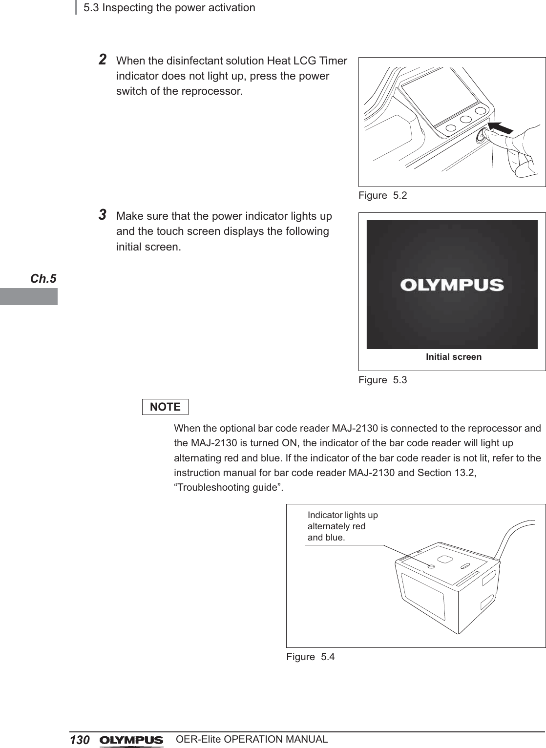
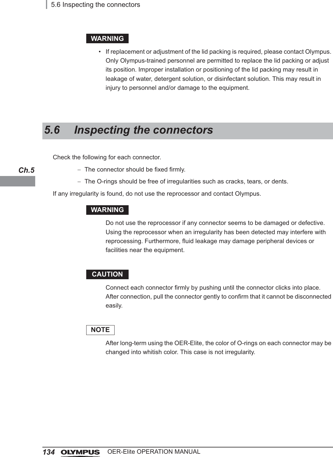
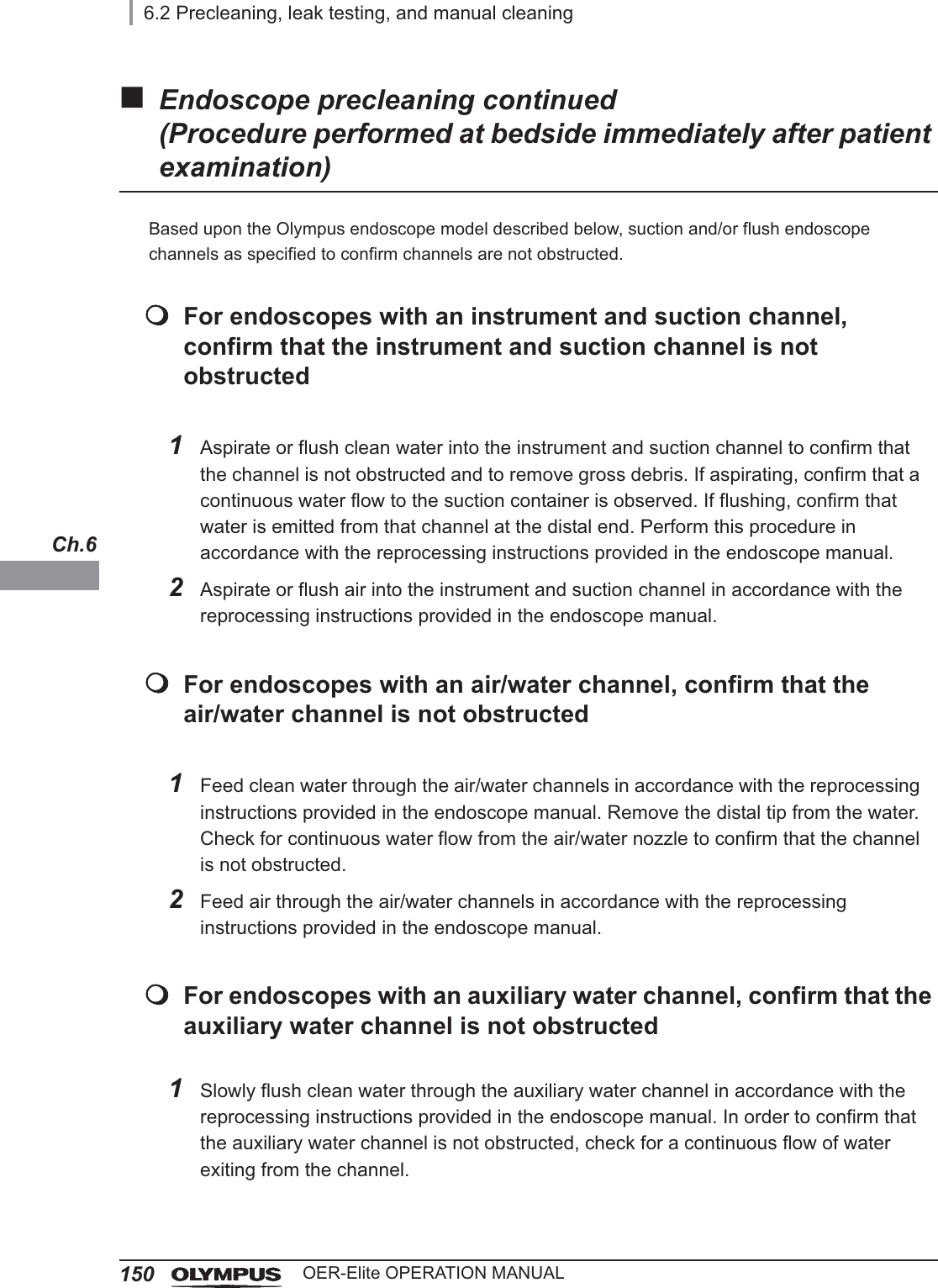
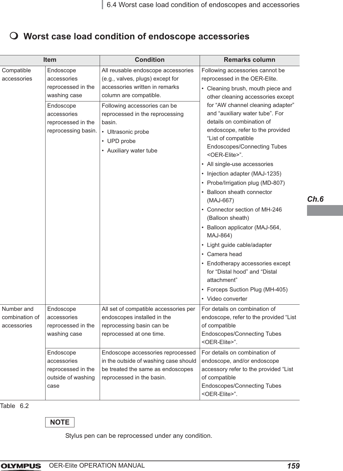
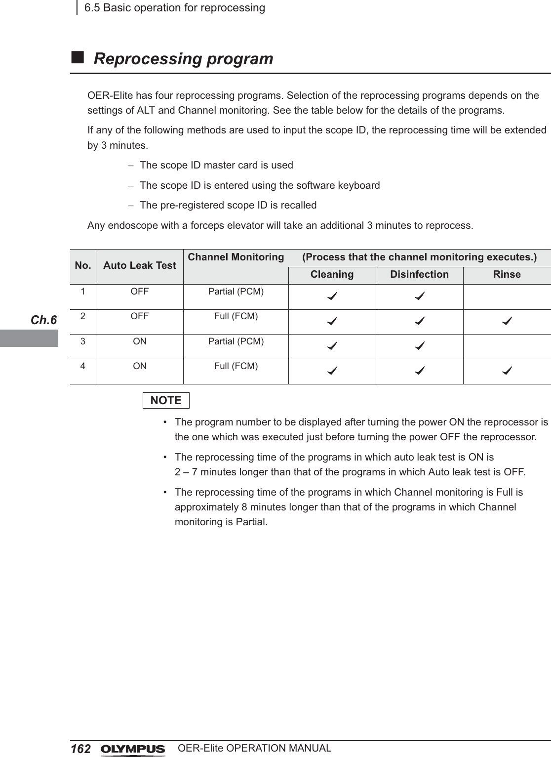
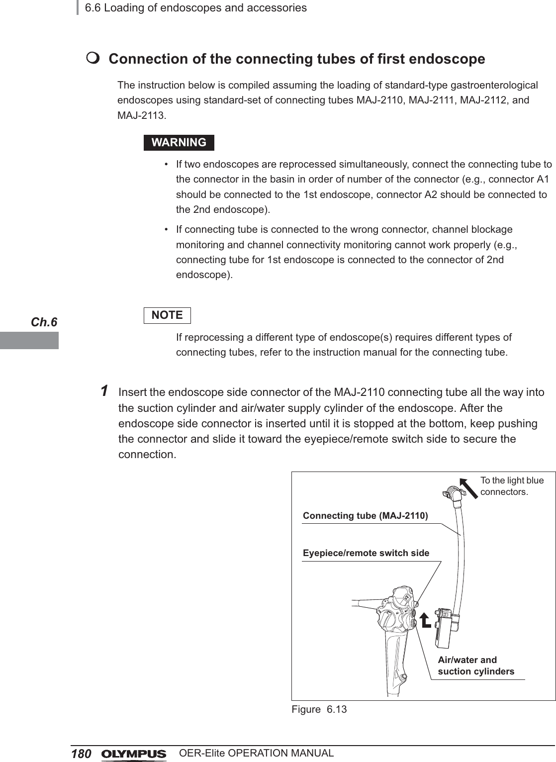
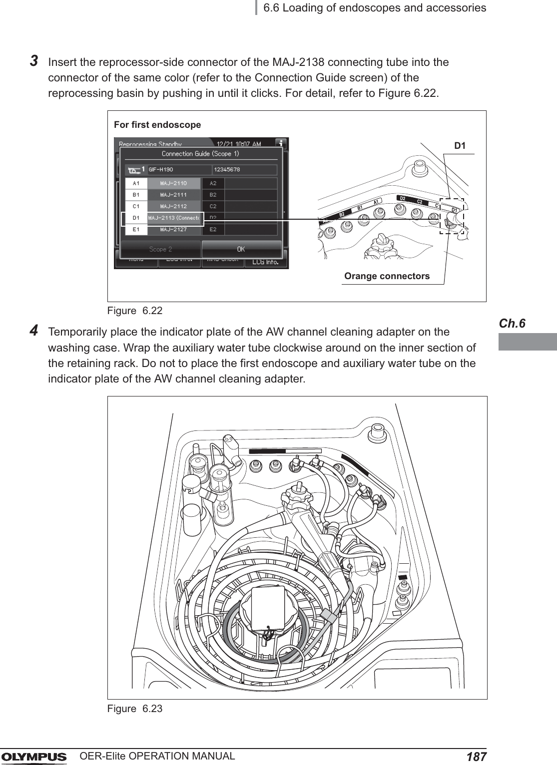
![2206.8 ReprocessingOER-Elite OPERATION MANUALCh.6The reprocessing time can be selected from four reprocessing programs [1] to [4]. The auto leak test and channel monitoring will be performed following the selected reprocessing program.If any of the following methods are used to input the scope ID, the reprocessing time will be extended by 3 minutes.The scope ID master card is usedThe scope ID is entered using the software keyboardThe pre-registered scope ID is recalledAny endoscope with a forceps elevator will take an additional 3 minutes to reprocess.Table 6.35Check the contents of the selected reprocessing program and status of IDs entry. Confirm that the checking of concentration of disinfectant solution and MRC check result entry is completed.Figure 6.576.8 ReprocessingNo. Auto leak Test Channel Monitoring (Process that the channel monitoring executes.)Cleaning Disinfection Rinse1 OFF Partial (PCM)2 OFF Full (FCM)3 ON Partial (PCM)4 ON Full (FCM)Process time of selected reprocessing programContents of the selected reprocessing program](https://usermanual.wiki/Olympus-Medical-Systems/RU2020.Operation-Manual-2/User-Guide-3575673-Page-92.png)
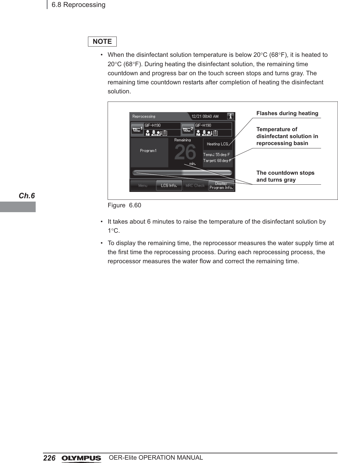
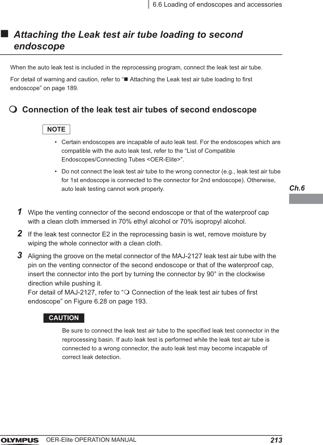
![6.8 Reprocessing221OER-Elite OPERATION MANUALCh.6Auto leak testThis reprocessor can automatically detect a leak in the endoscope during the reprocessing cycle. The results can be recorded in the reprocessing record. The auto leak test can reduce the mistakes of manual leak test. In addition to this function, also be sure to perform a leak test before performing manual cleaning.Not all endoscopes are capable of auto leak test. For the endoscopes with the auto leak test capability, refer to the “List of Compatible Endoscopes/Connecting Tubes <OER-Elite>”.If the scope ID is input by using the scope ID master card, input by the software keyboard or input by recalling the pre-registered ID, the auto leak test is not available.The timing of the auto leak test can be selected at the start of reprocessing or at the end of reprocessing by ALT setting. Refer to Section 6.8, “Reprocessing”.When the reprocessor detects disconnection of the leak test air tube during the reprocessing process, it generates error code [E024] and stops the process.For the related setting changes, refer to Section 4.2, “Auto leak test setting”.At the start of reprocessingWhen warm water is used in manual cleaning, the result of the auto leak test may be erroneous because the internal pressure of endoscope(s) is unstable due to temperature change. If the auto leak test is to be performed at the start of reprocessing, begin the reprocessing process after the endoscope temperature has returned to the room temperature. To return the room temperature, it takes 15 minutes for endoscopes other than ultrasonic endoscopes and 30 minutes for ultrasonic endoscopes. When the auto leak test is performed at the start of reprocessing, the reprocessing time is extended for about 2 minutes. If leak is detected with an endoscope, follow the procedure for leaking scope decontamination on it and contact Olympus for servicing. For details on the leaking scope decontamination, refer to Section 7.15, “Leaking scope decontamination”.At the end of reprocessingWhen the auto leak test is performed at the end of reprocessing, the reprocessing time is extended for about 2 – 7 minutes depending on the type of endoscopes and the atmospheric temperature surrounding the reprocessor.If there is a leak with an endoscope, water may enter the endoscope from the leakage point.](https://usermanual.wiki/Olympus-Medical-Systems/RU2020.Operation-Manual-2/User-Guide-3575673-Page-93.png)
![2226.8 ReprocessingOER-Elite OPERATION MANUALCh.6WARNING• When water leak is detected with one endoscope, the other endoscope without water leak might be reprocessed insufficiently. In this case, perform the reprocessing process again.• Avoid exposure to direct sunlight or air conditioning vents. If there is drastic temperature change due to the exposure to direct sunlight or air conditioning, the leak test result may be erroneous.• If the leak test result is “Fail”, do not execute reprocessing process. In this case, perform the leaking scope decontamination process with the leaking endoscope and contact Olympus for servicing. For details on the leaking scope decontamination process, refer to Section 7.15, “Leaking scope decontamination”.CAUTION• Even if the auto leak test is incorporated in the reprocessing program, be sure to perform manual leak test before manual cleaning. If water leaks occur with an endoscope, fluid invasion and damage to the endoscope may occur during manual cleaning.• The touch screen may display error code [E114] (Leaked) due to the effect of the temperature of the endoscope(s). If this happens, execute the auto leak detection again after the endoscope temperature has returned to the room temperature. If error code [E114] is displayed again, perform the leaking scope decontamination process with the leaking endoscope and contact Olympus for servicing. For details on the leaking scope decontamination, refer to Section 7.15, “Leaking scope decontamination”.NOTE• The covering of the bending section of the endoscope may dilate slightly during the leak test. This is not malfunction.• The auto leak test may sometimes be incapable of detecting a very small hole.](https://usermanual.wiki/Olympus-Medical-Systems/RU2020.Operation-Manual-2/User-Guide-3575673-Page-94.png)
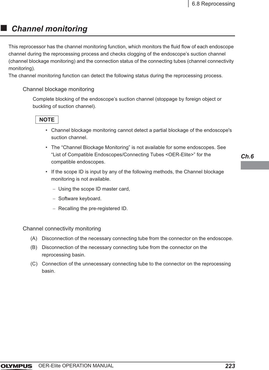
![2246.8 ReprocessingOER-Elite OPERATION MANUALCh.6NOTE• Disconnection of the necessary connecting tube from the connector on the endoscope cannot be detected for some endoscopes. See “List of Compatible Endoscopes/Connecting Tubes <OER-Elite>” for the compatible endoscopes.• If the scope ID is input in any of the following methods, the function (A) would not work.The scope ID master card is usedThe scope ID is entered using the software keyboardThe pre-registered scope ID is recalled• If a connecting tube is disconnected, the channel blockage monitoring may not work properly and this reprocessor may detect disconnection of the other connecting tubes from the connector on the endoscope despite the fact that they are connected properly.When the channel monitoring is detected during the reprocessing process, the reprocessor displays error code [E024] on the touch screen and stops the process.The detection timings can be selected from “PCM (partial channel monitoring)” for detection in the cleaning and disinfection processes and “FCM (full channel monitoring)” for detection in the cleaning, disinfection and rinsing processes. The selected detection timings are recorded in the reprocessing process record. When “FCM (full channel monitoring)” is selected, the process time extends by about 8 minutes. For the setting change, refer to Section 6.5, “Basic operation for reprocessing”.CAUTIONThe following procedures must be performed. Otherwise, the channel monitoring may not be able to detect clogged suction channel of the endoscope or improper connection of the connecting tubes.Clean the Circulation port mesh filters at the end of every working day.Check that the connectors on the reprocessing basin are not damaged prior to every use.Check that the connecting tubes are not damaged prior to every use.The endoscope(s) must be placed in the reprocessing basin in accordance with the instructions in Chapter 6.](https://usermanual.wiki/Olympus-Medical-Systems/RU2020.Operation-Manual-2/User-Guide-3575673-Page-96.png)