Olympus Medical Systems RU2020 Endoscope Reprocessor User Manual GT9882 0100 fm10
Olympus Medical Systems Corp. Endoscope Reprocessor GT9882 0100 fm10
UserManual.wiki
>
Olympus Medical Systems
>
RU2020 User Manual
>
Operation Manual 3
Contents
1.
Operation Manual 1
2.
Operation Manual 2
3.
Operation Manual 3
4.
Operation Manual 4
5.
Operation Manual 5
6.
Installation Manual 1
7.
Installation Manual 2
Operation Manual 3
Navigation menu
Upload a User Manual
Namespaces
Wiki Guide
HTML
PDF
Info
Views
User Manual
Discussion / Help
Navigation
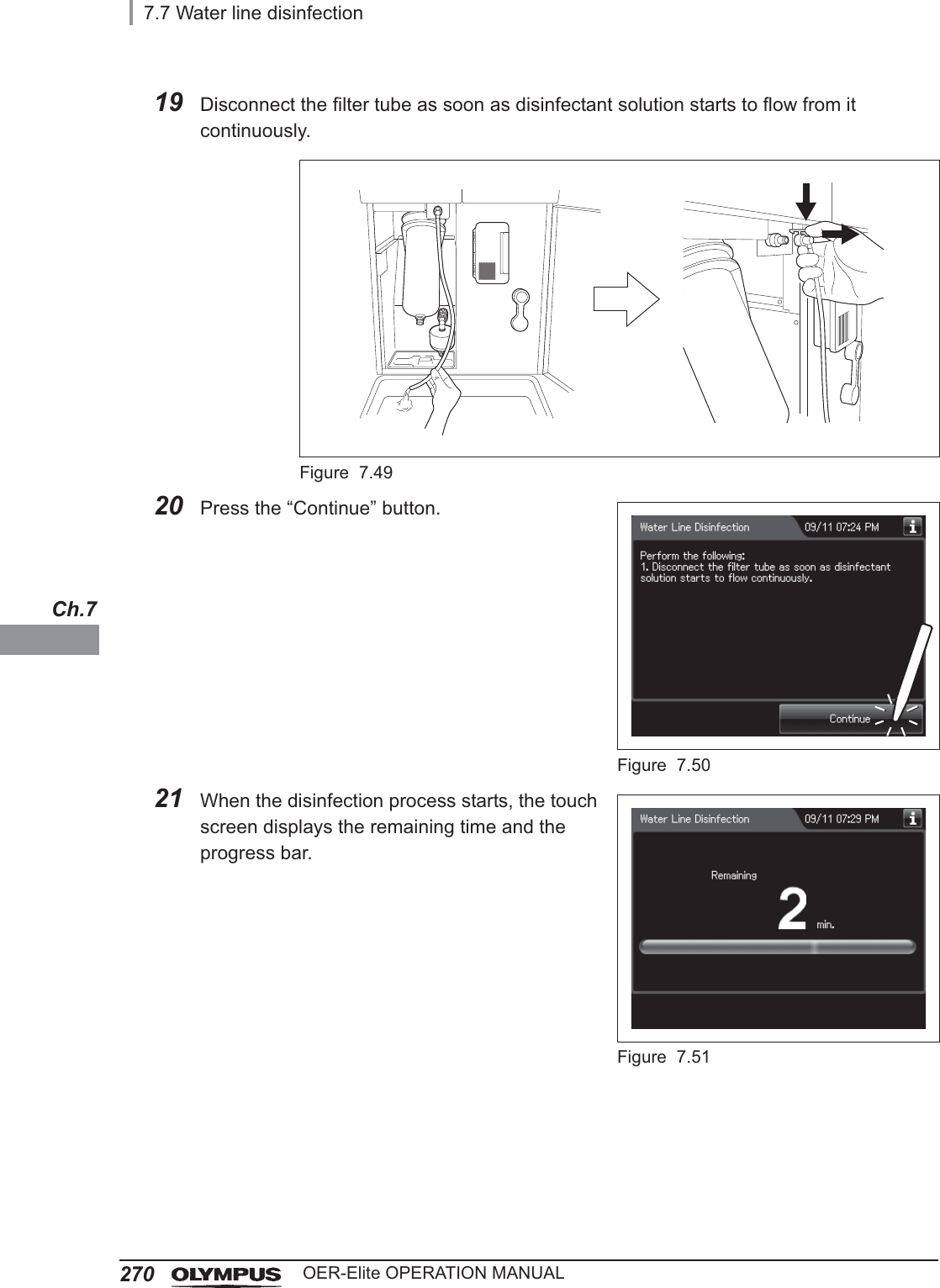
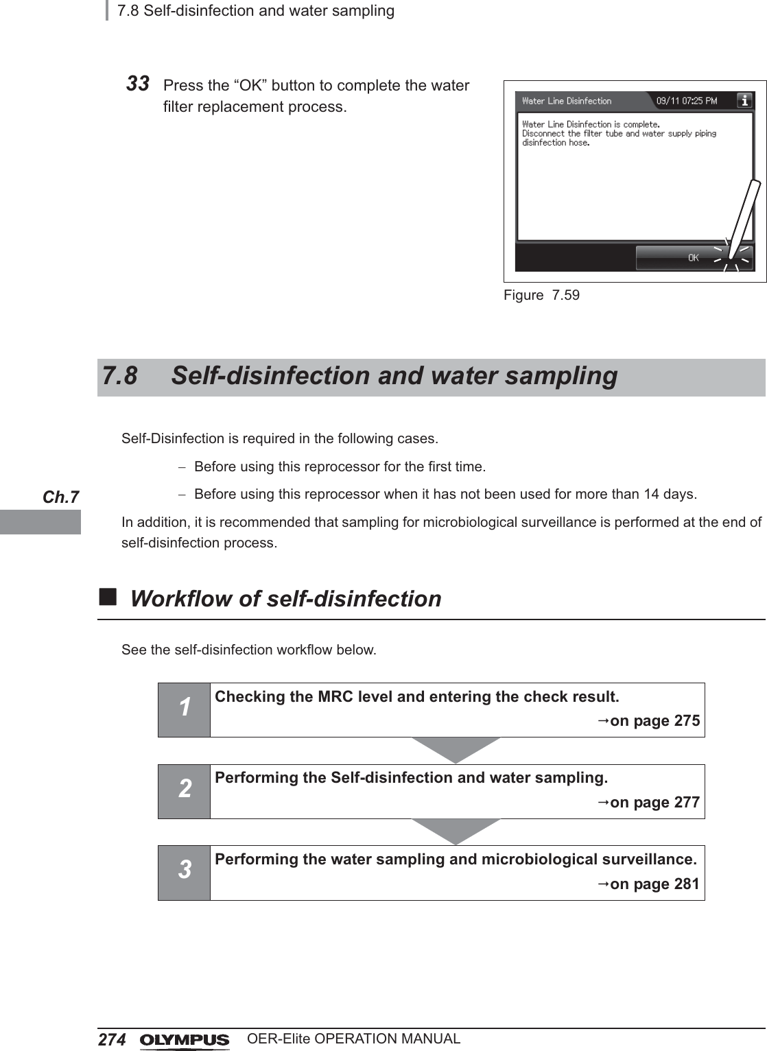
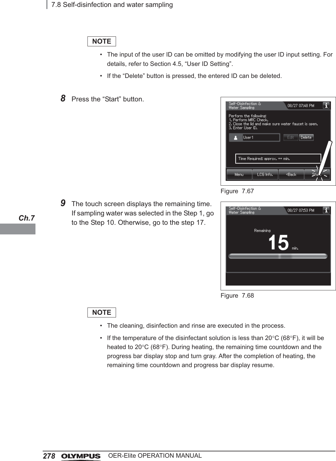
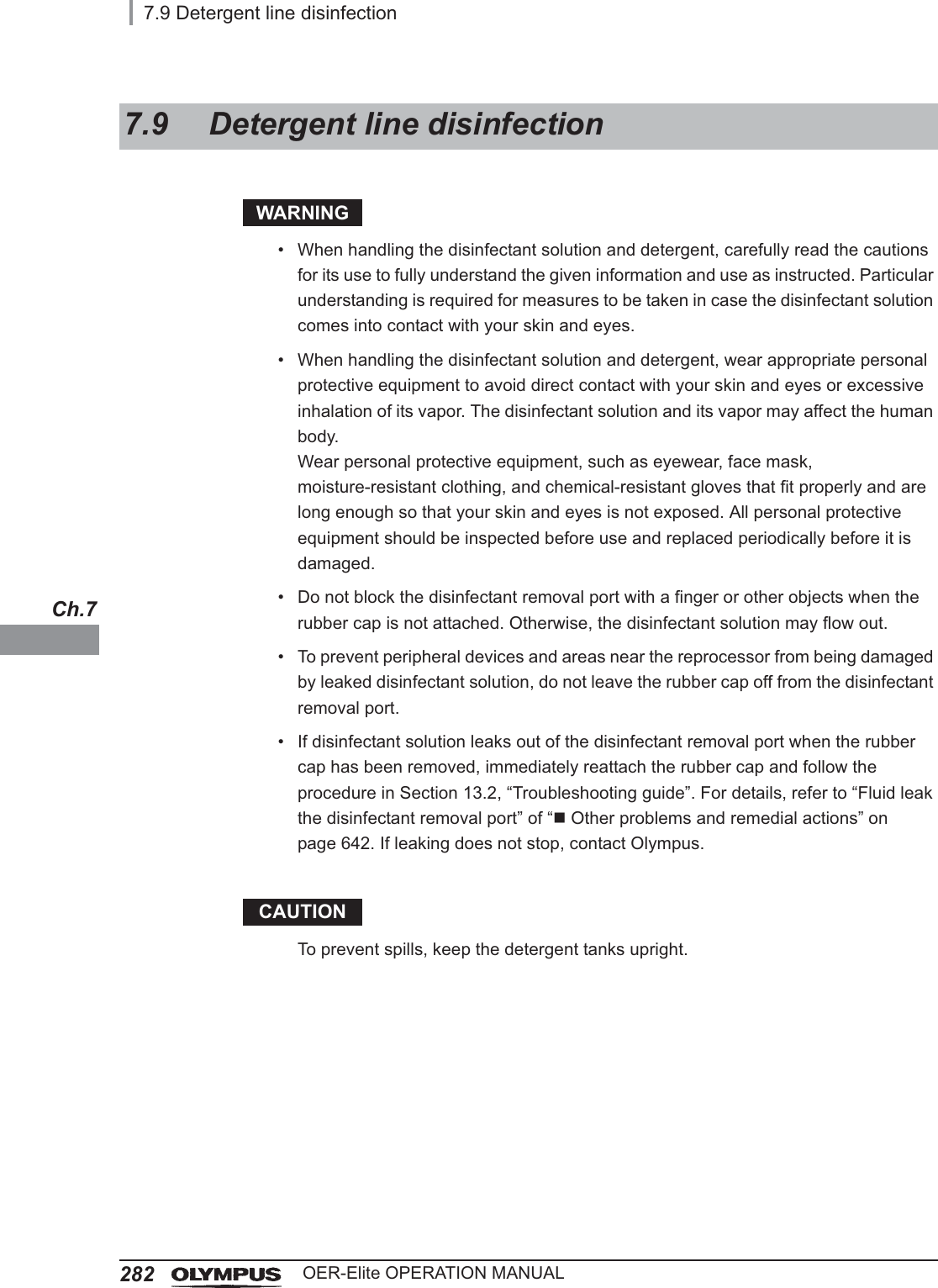
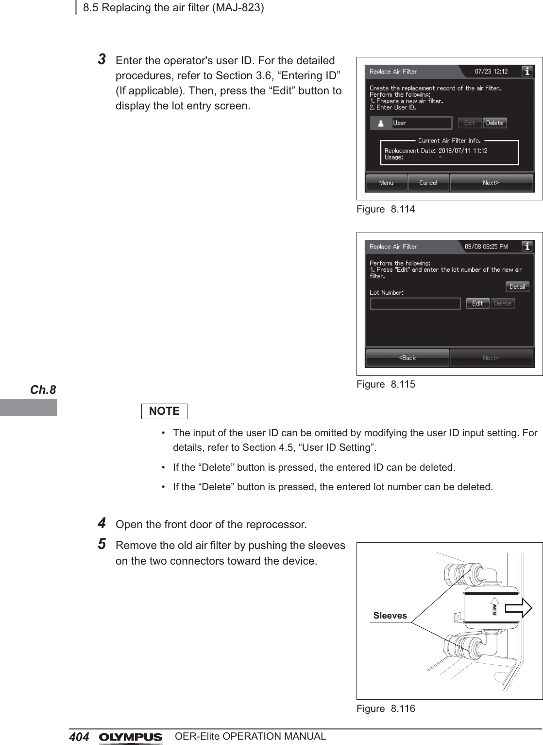
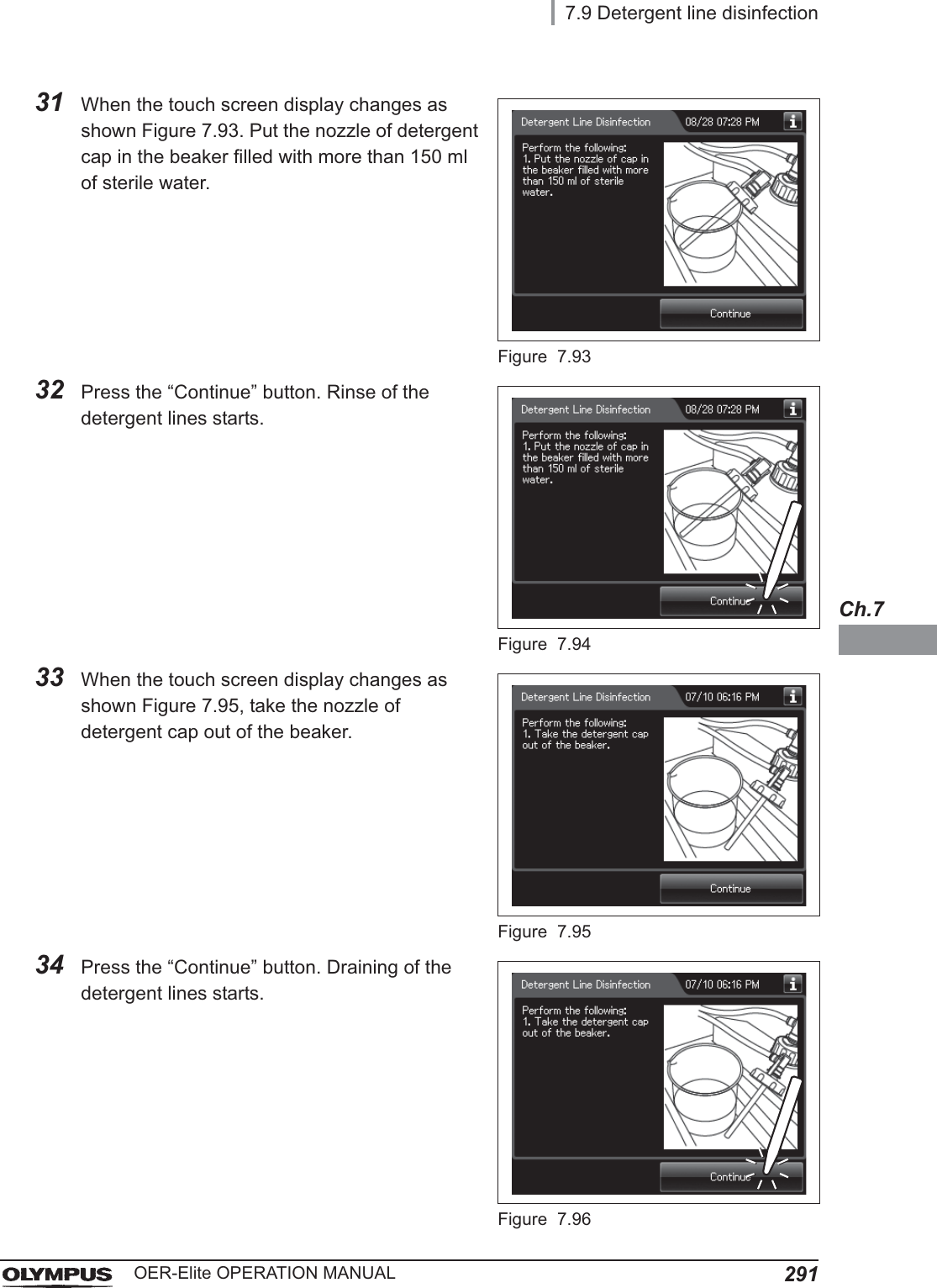
![2847.9 Detergent line disinfectionOER-Elite OPERATION MANUALCh.74Press the “Detergent Line Disinfection” button.Figure 7.745Press the “Next” button.Figure 7.756Push [PUSH] on the front door to open the front door. Remove the rubber cap from the disinfectant removal port.Figure 7.767Push the drain connector into the disinfectant removal port until it clicks.WARNINGWhen connecting the drain connector to the disinfectant removal port, do not push on the connector’s valve. Otherwise, disinfectant solution will leak out of it.Disinfectant removal portRubber cap](https://usermanual.wiki/Olympus-Medical-Systems/RU2020.Operation-Manual-3/User-Guide-3575683-Page-18.png)
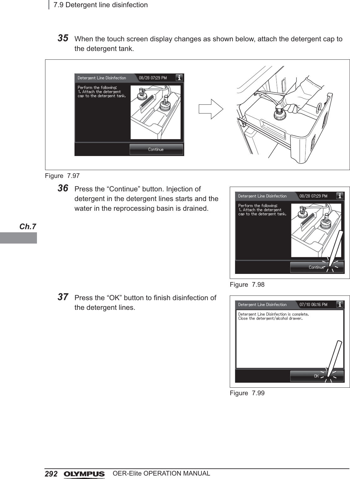
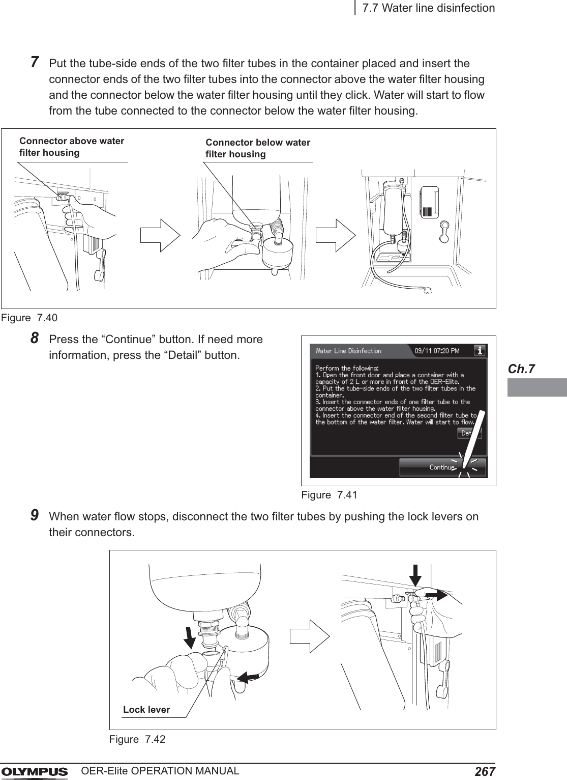
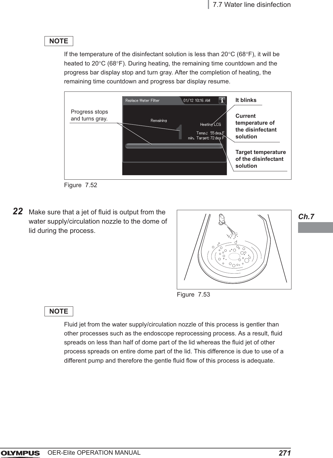
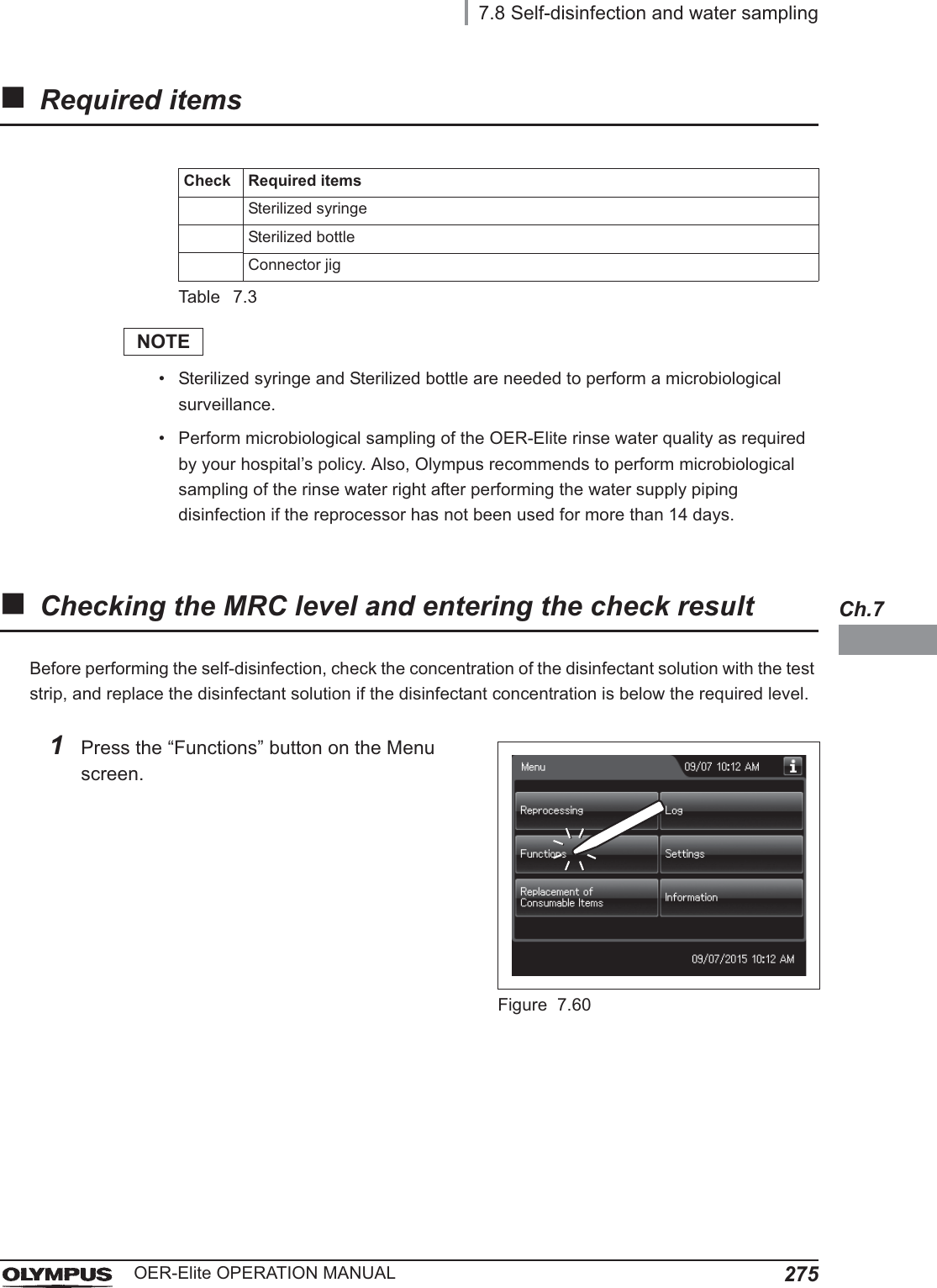
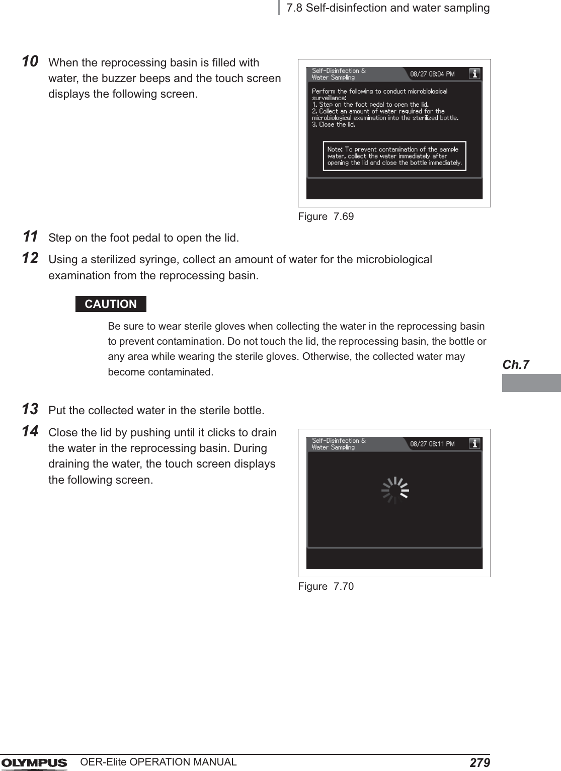
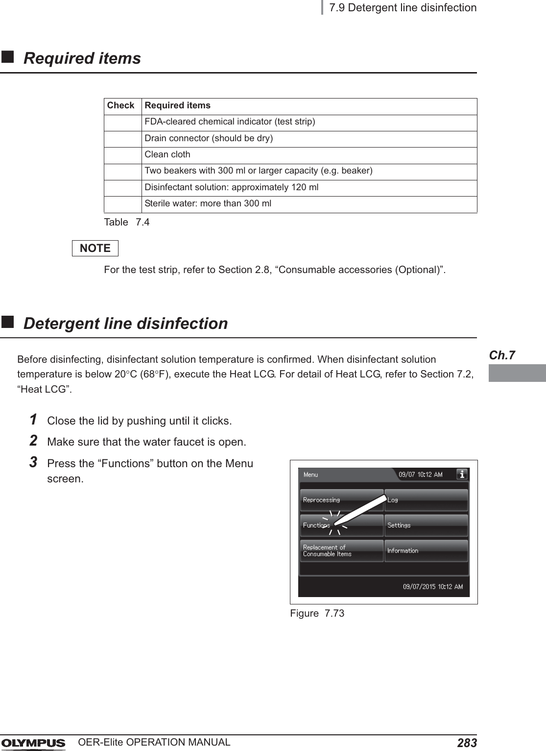
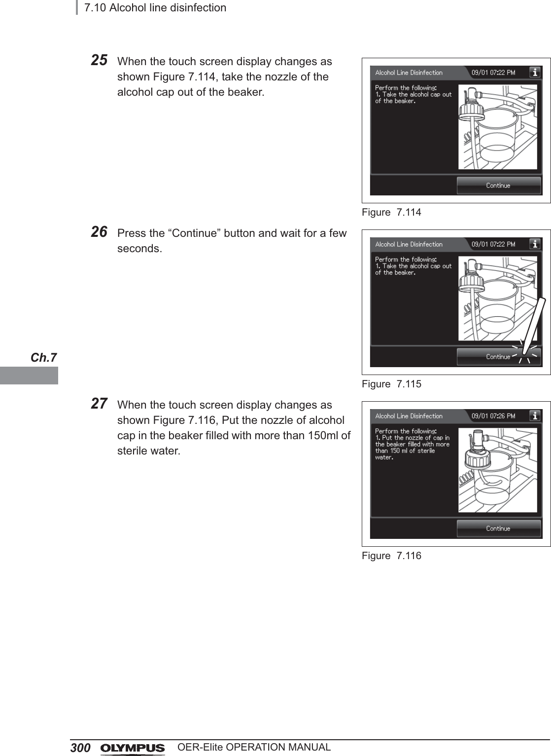
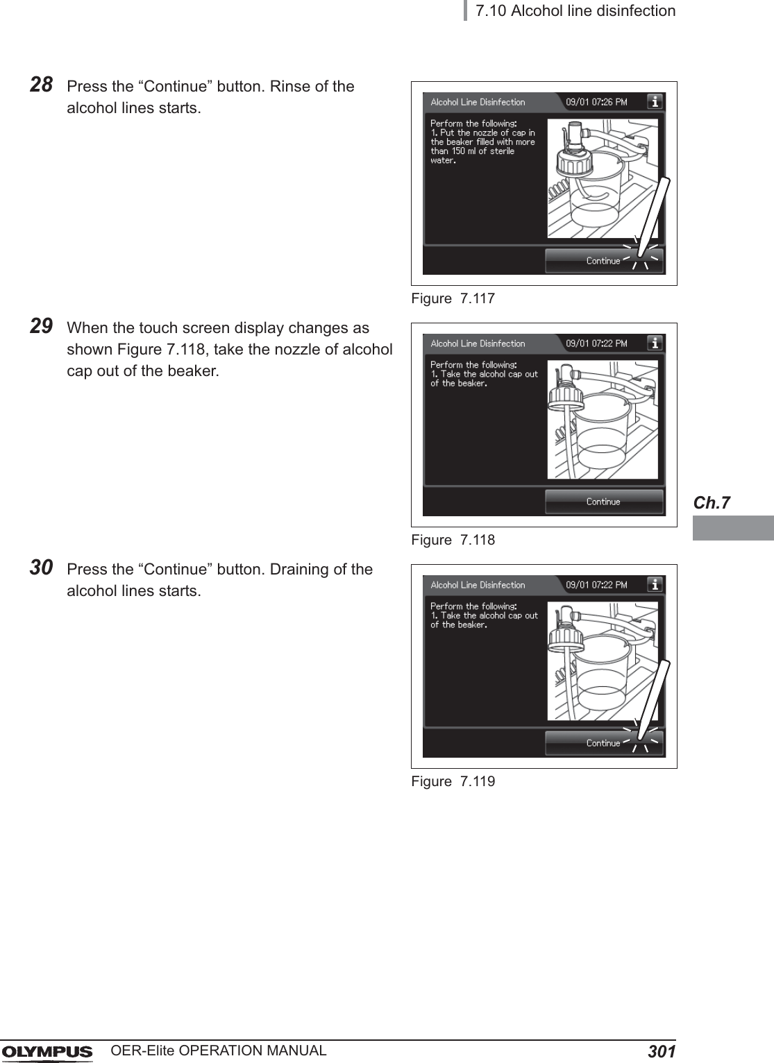
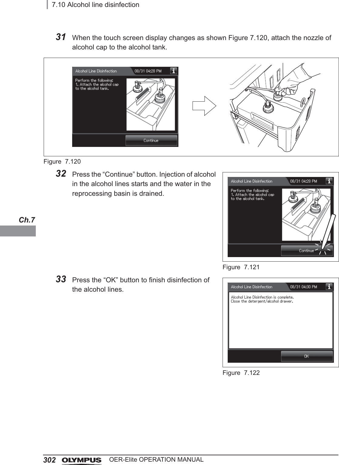
![7.10 Alcohol line disinfection295OER-Elite OPERATION MANUALCh.74Press the “Alcohol Line Disinfection” button.Figure 7.1015Press the “Next” button.Figure 7.1026Push [PUSH] on the front door to open the front door. Remove the rubber cap from the disinfectant removal port.Figure 7.1037Push the drain connector into the disinfectant removal port until it clicks.WARNINGWhen connecting the drain connector to the disinfectant removal port, do not push on the connector’s valve. Otherwise, disinfectant solution will leak out of it.Disinfectant removal portRubber cap](https://usermanual.wiki/Olympus-Medical-Systems/RU2020.Operation-Manual-3/User-Guide-3575683-Page-29.png)
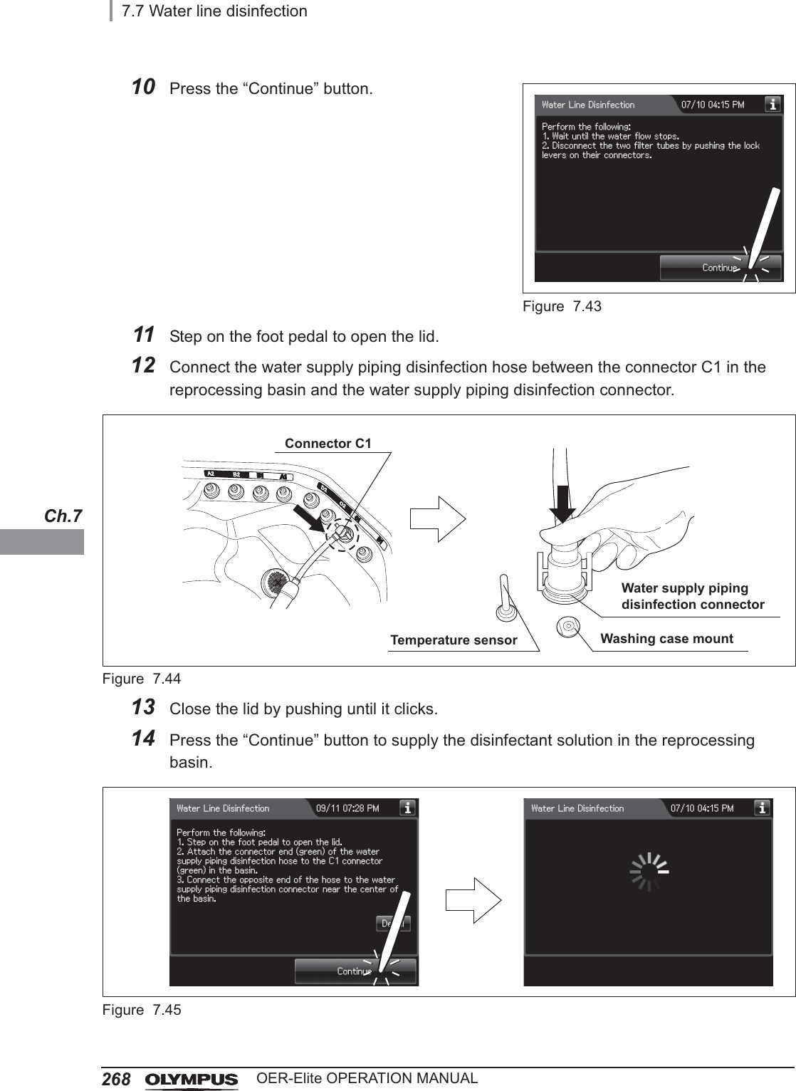
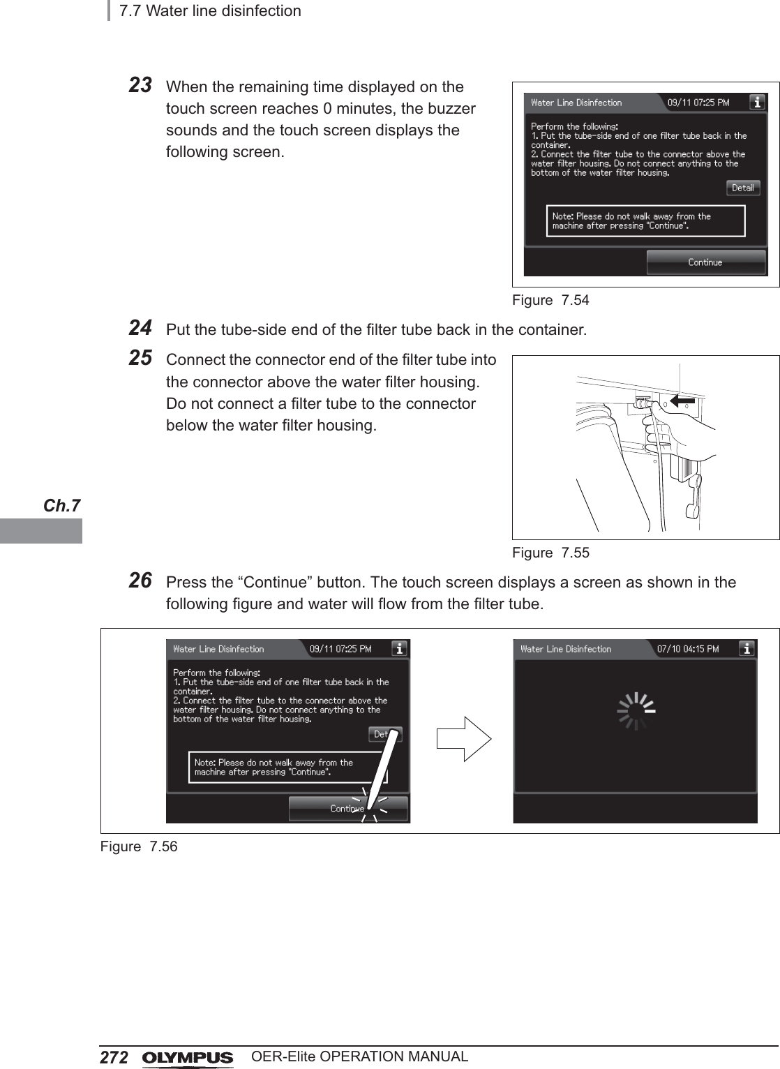
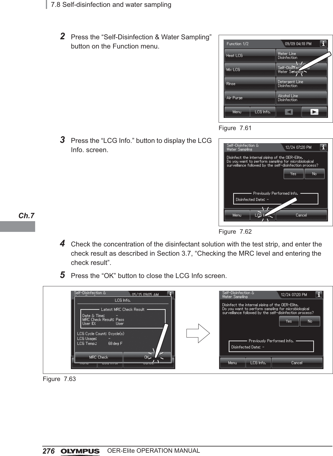
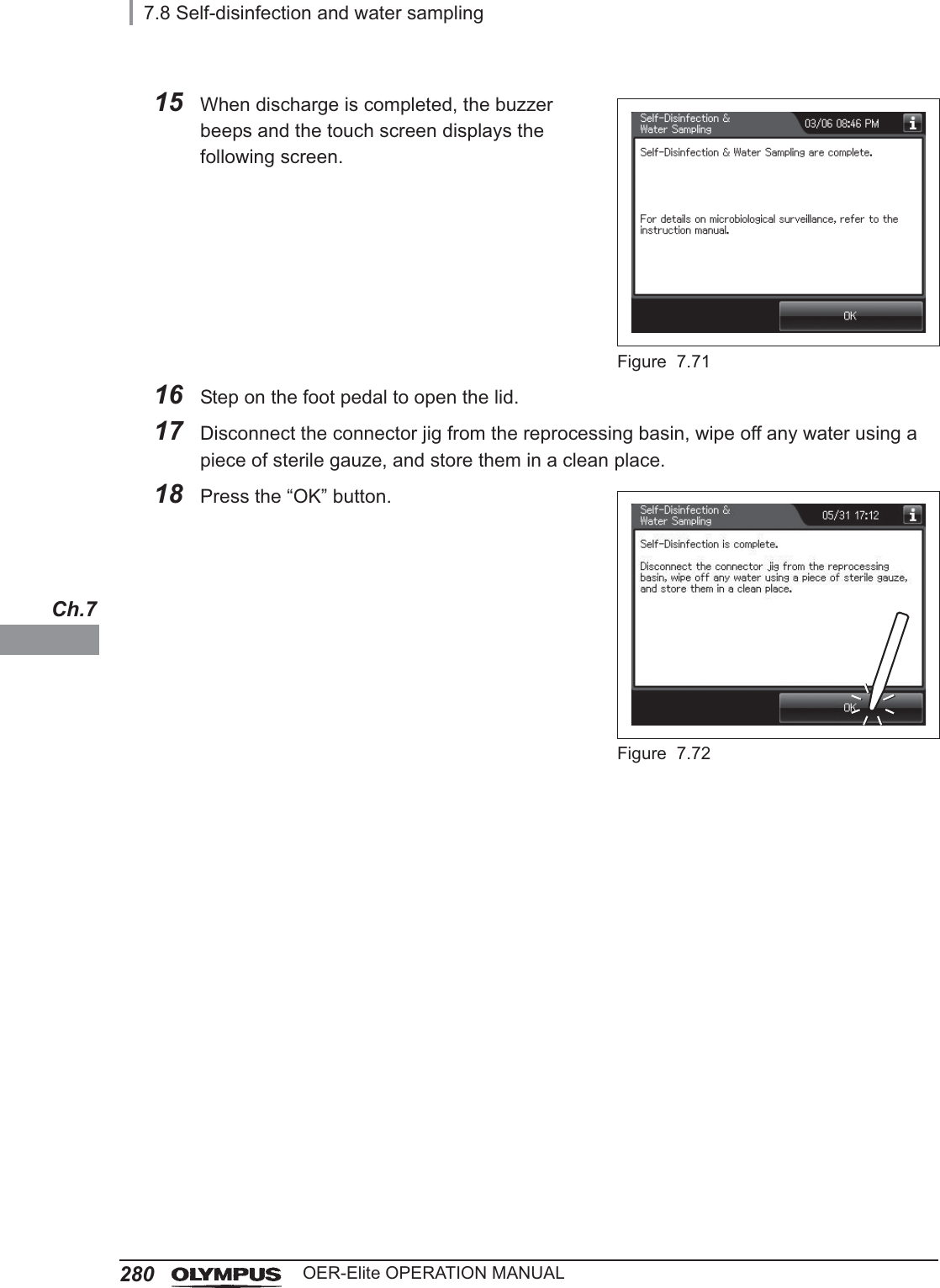
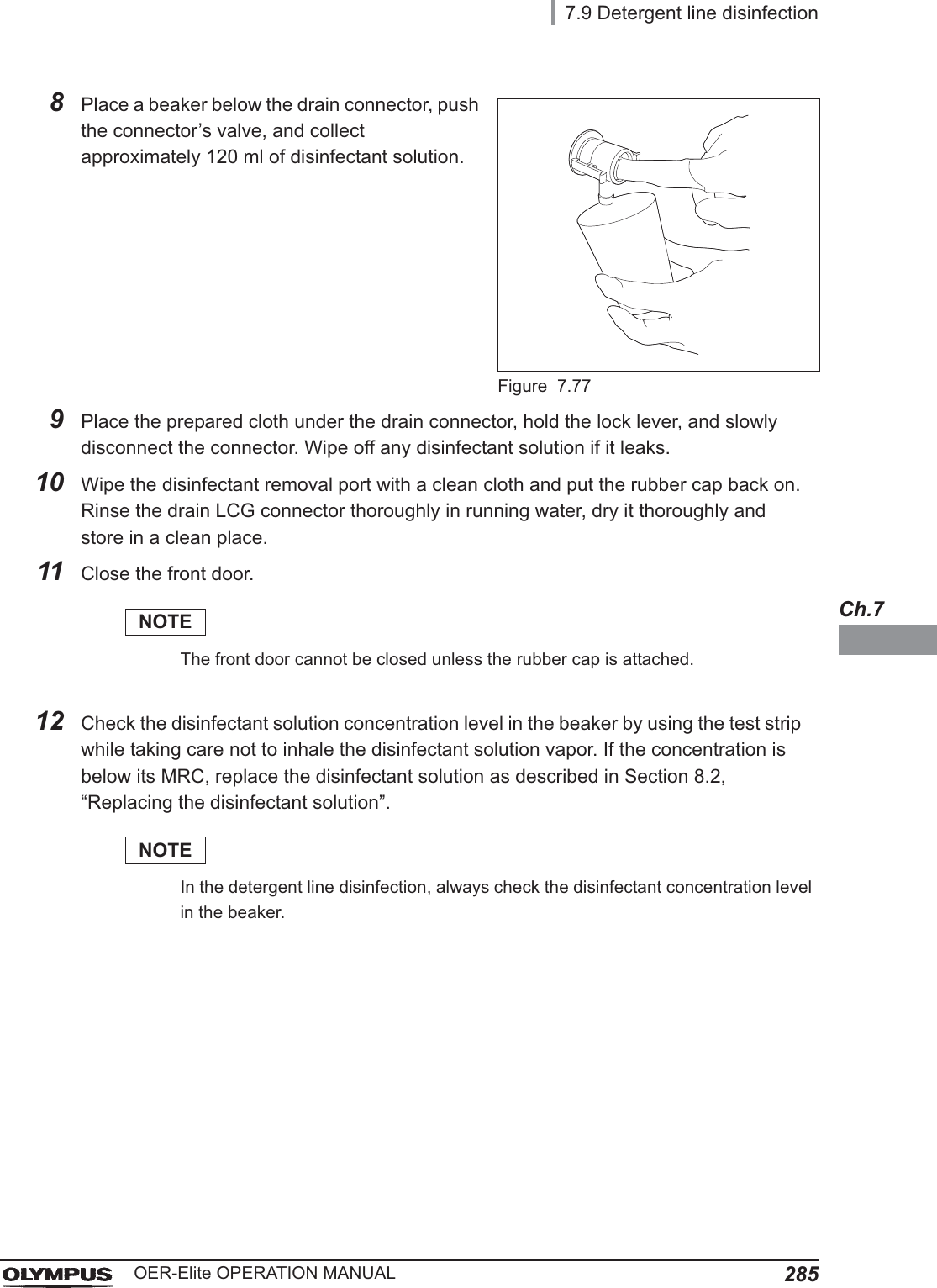
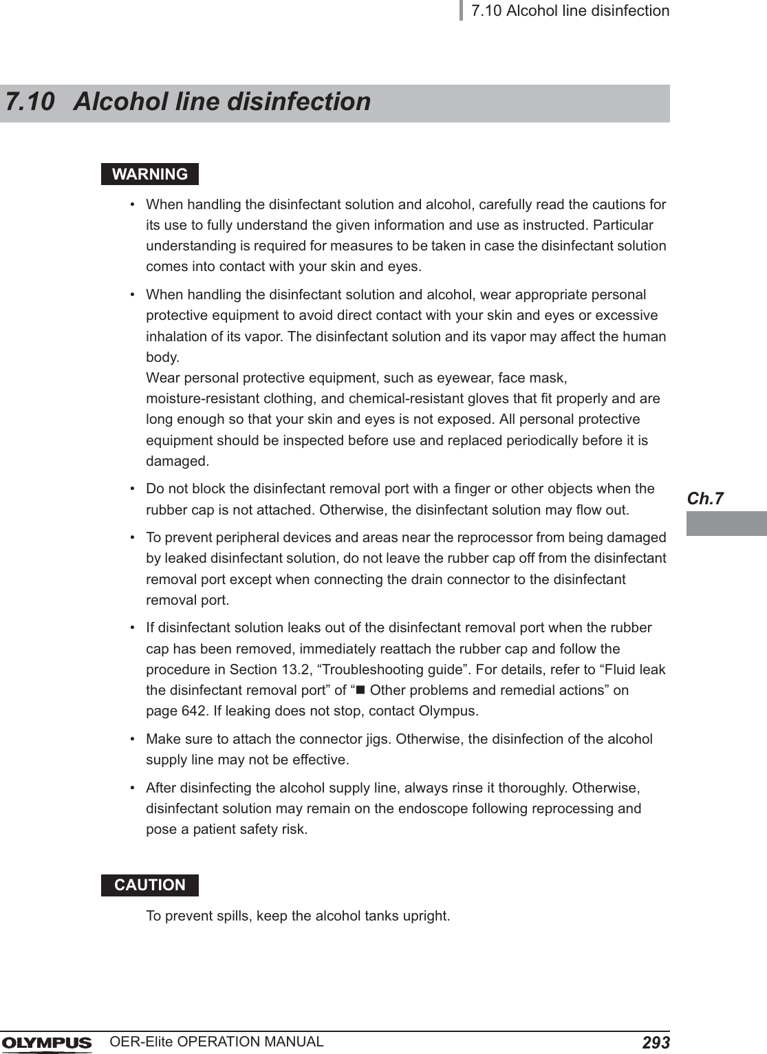
![3087.11 Manual leak testOER-Elite OPERATION MANUALCh.715 When the water supply completes, the reprocessor generates three buzzer beeps and unlock the lid.Figure 7.12916 Ensure that the water supply is stopped and then step on the foot pedal to open the lid. When the lid is opened, the touch screen displays the following screen. Perform from Step 16 to Step 19 within 10 minutes after opening the lid.Figure 7.130NOTEIf the lid is not opened within 10 minutes, the fluid in the reprocessing basin is drained automatically and the manual leak test stops. The touch screen will then display the error code [E092].17 Check that there are not any bubbles produced continuously from the outer surface of the endoscope and/or leak test air tube while angulating the bending section of the endoscope. Check for leaks at least for 30 seconds.CAUTION• When angulating the endoscope’s bending section, do not to let the bending section touch the reprocessing basin or retaining rack as this could damage the endoscope. After bending, straighten the bending section and place it properly on the retaining rack.• During the manual leak test, be sure to angulate the bending section. Otherwise, it would be impossible to find abnormalities in the endoscopes.](https://usermanual.wiki/Olympus-Medical-Systems/RU2020.Operation-Manual-3/User-Guide-3575683-Page-42.png)
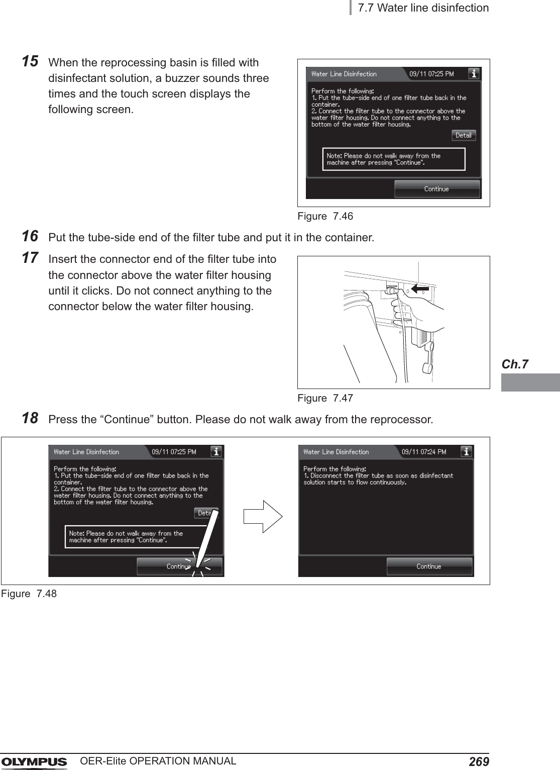
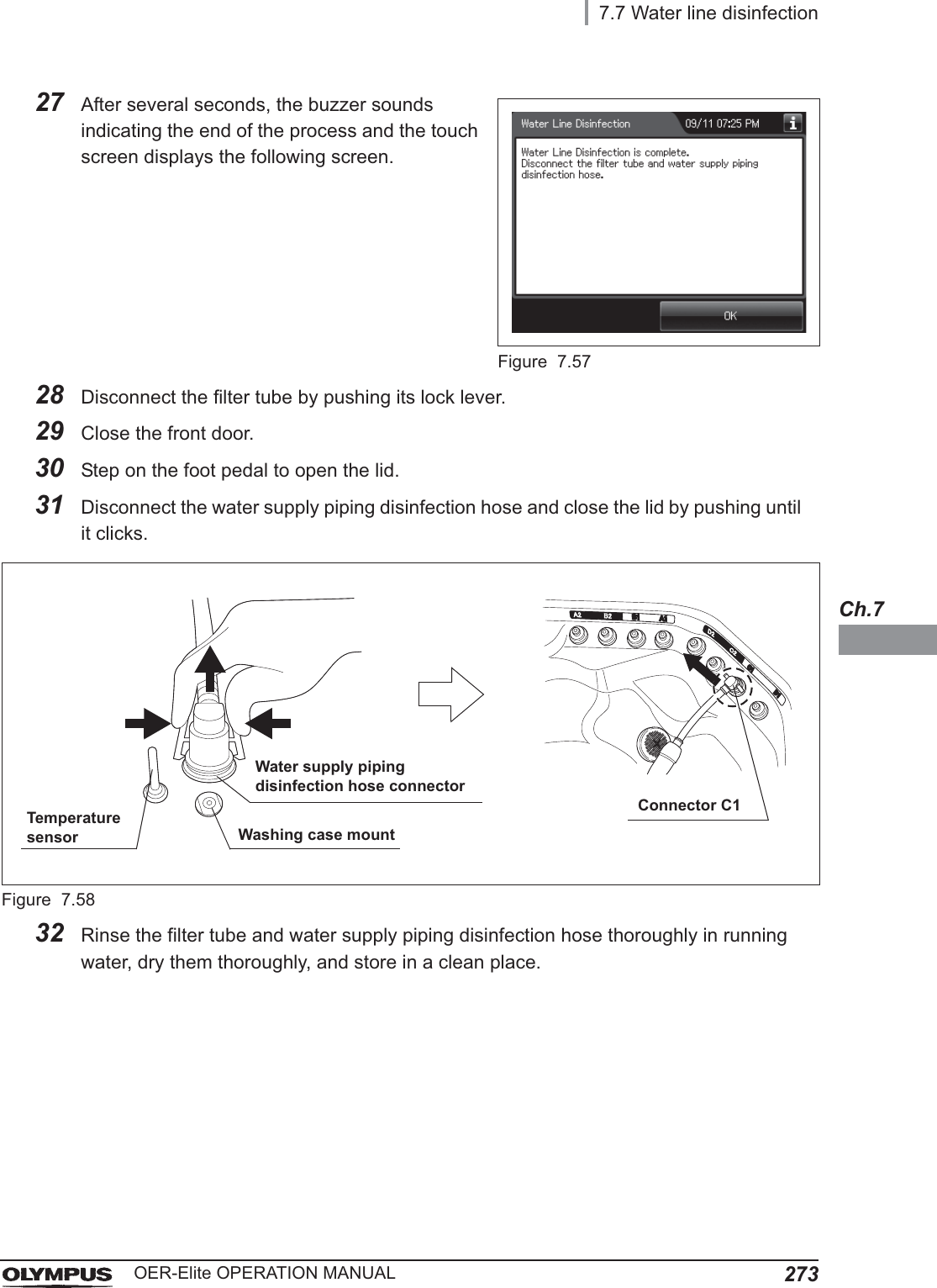
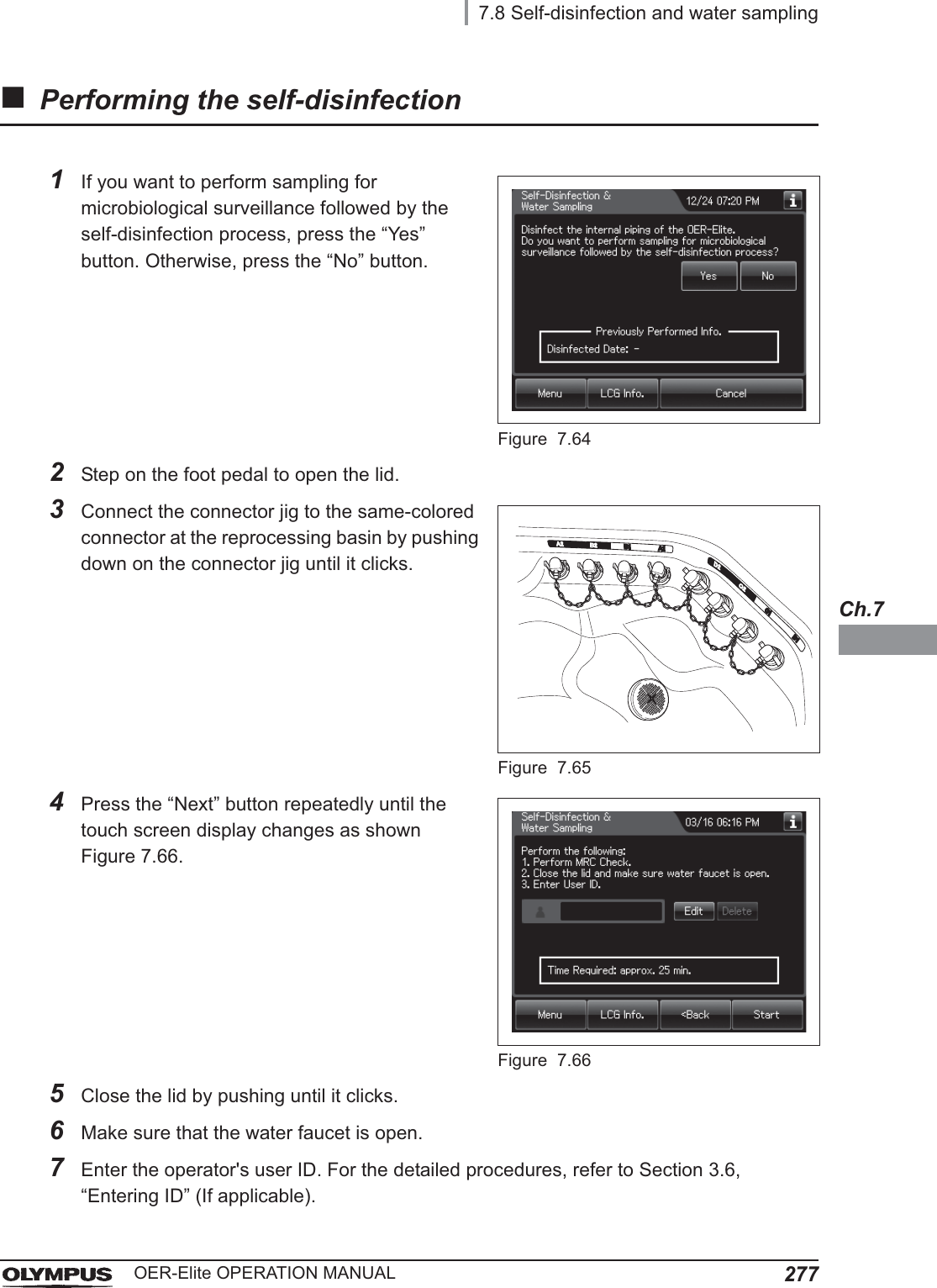
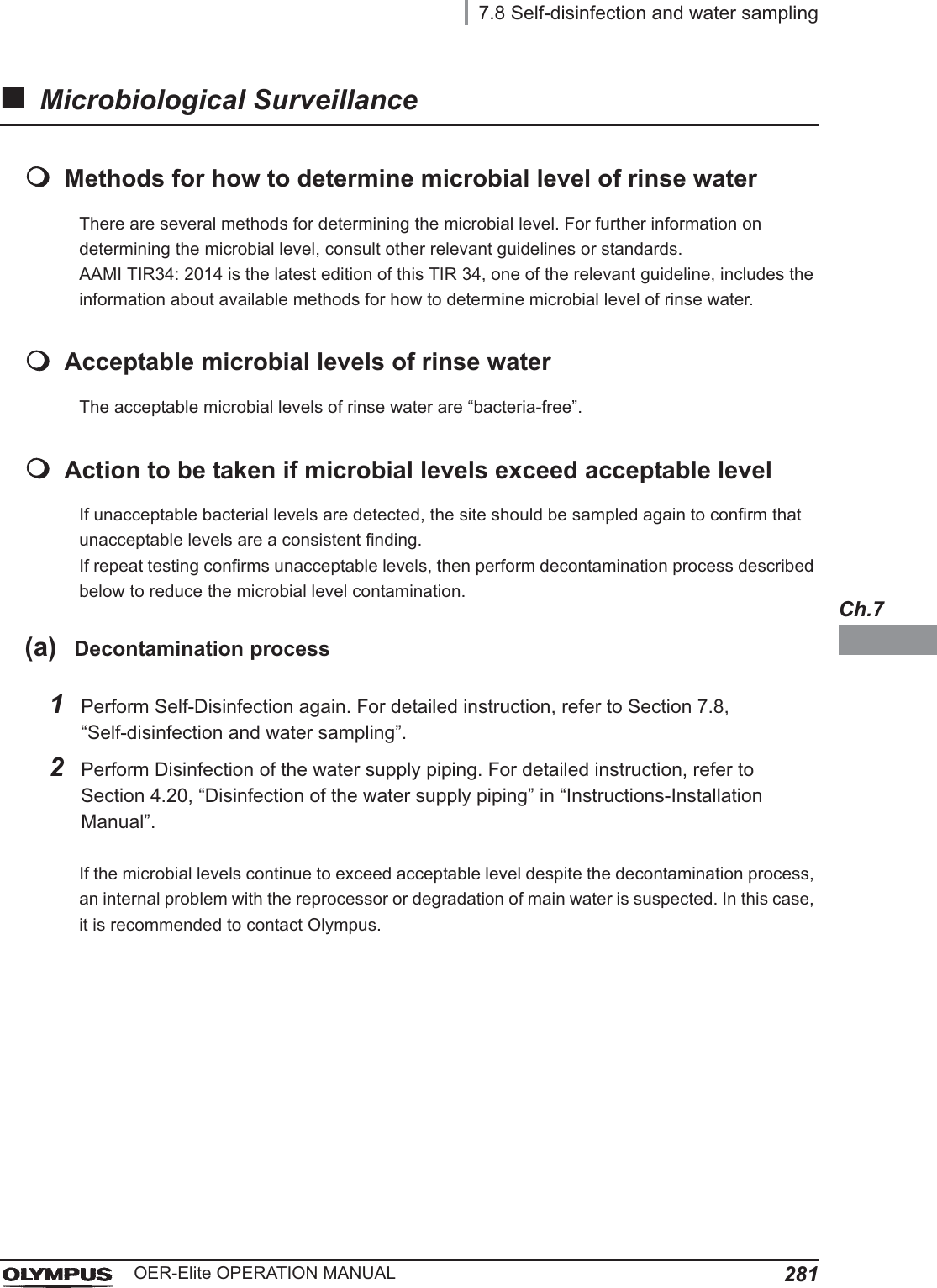
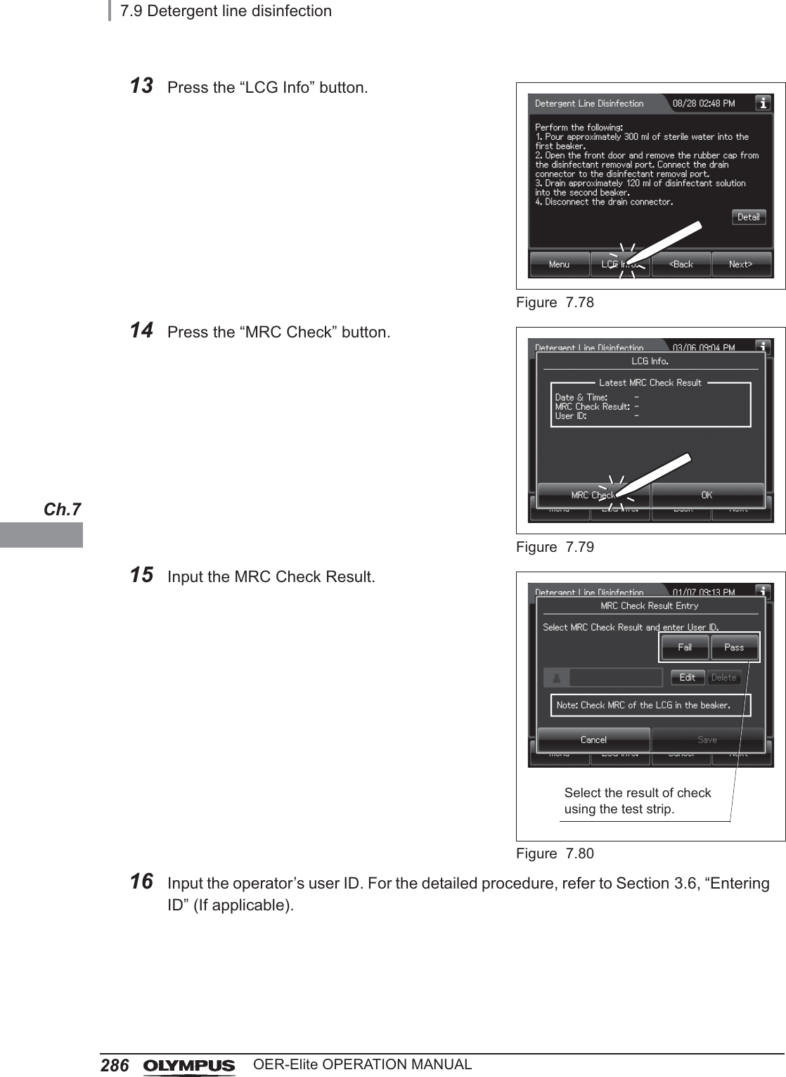
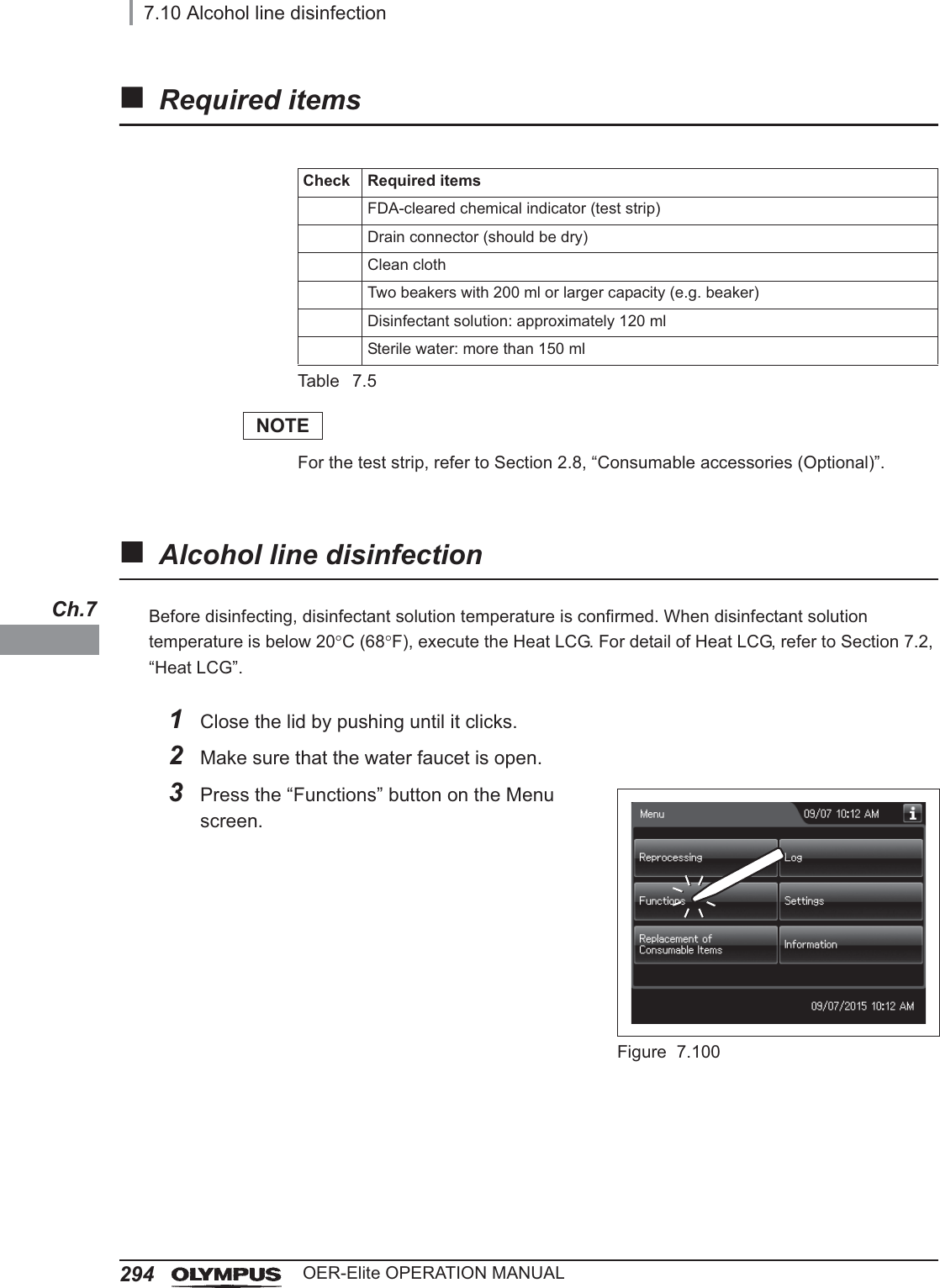
![7.11 Manual leak test309OER-Elite OPERATION MANUALCh.7NOTE• Adjust the position of endoscope to immerse all outer surface of endoscope in the water as needed.• If you set two endoscopes in the basin, it may be difficult to sufficiently immerse endoscopes to inspect bubbles. In this case, perform the leakage test for each endoscope separately.18 Press the “Continue” button, and then input each manual leak test result on the touch screen.Figure 7.13119 Close the lid by pushing until it clicks. The water starts to be drained.NOTEEven if the process is not completed by closing the lid, the water is drained automatically 10 minutes after the water supply stopped. The touch screen will then display error code [E092].20 When draining has completed, the reprocessor generates three buzzer beeps and the touch screen shows the following screen. Press the “OK” button to finish.Figure 7.132Selection of leak test Result for each endoscope](https://usermanual.wiki/Olympus-Medical-Systems/RU2020.Operation-Manual-3/User-Guide-3575683-Page-43.png)
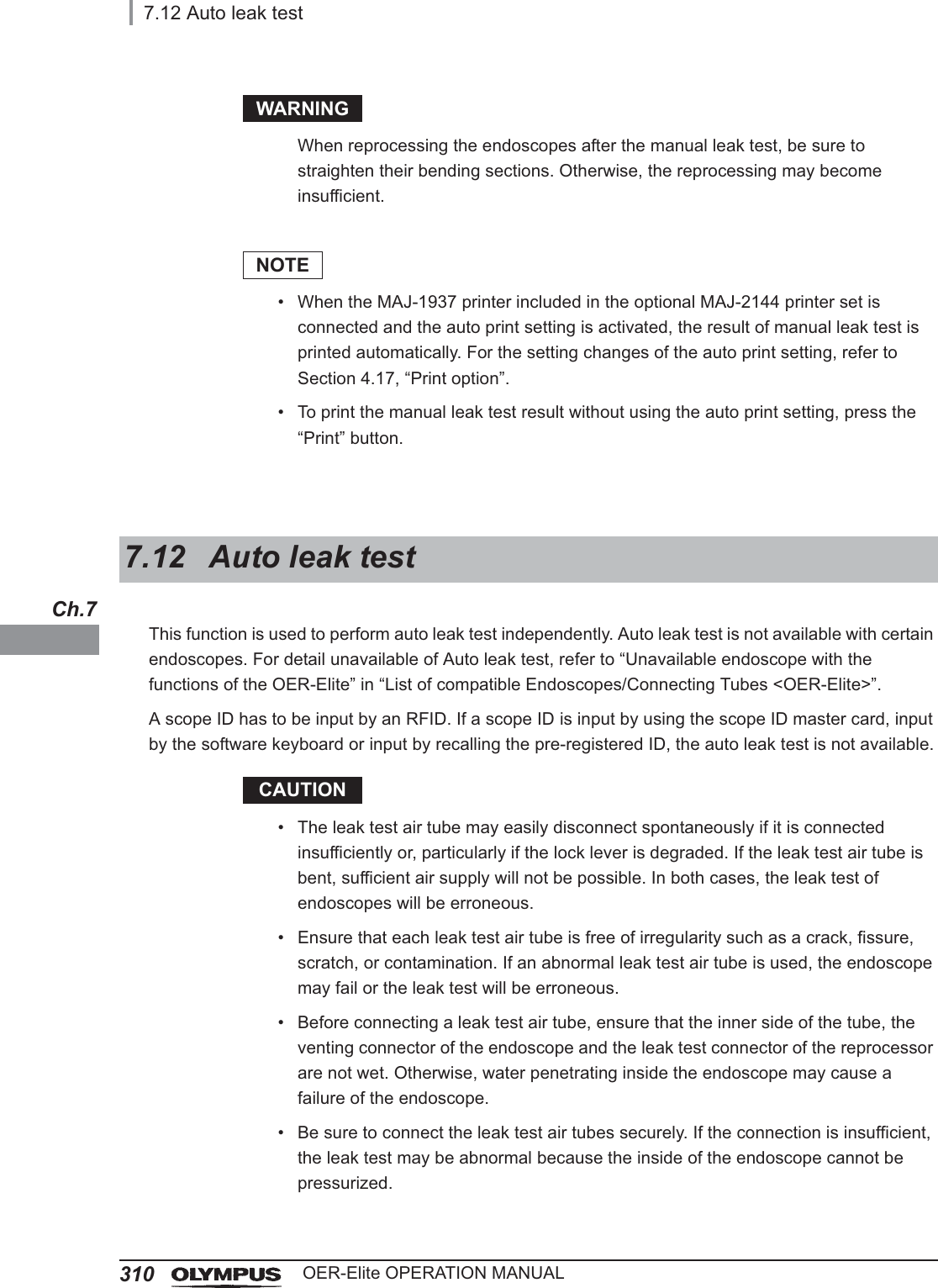
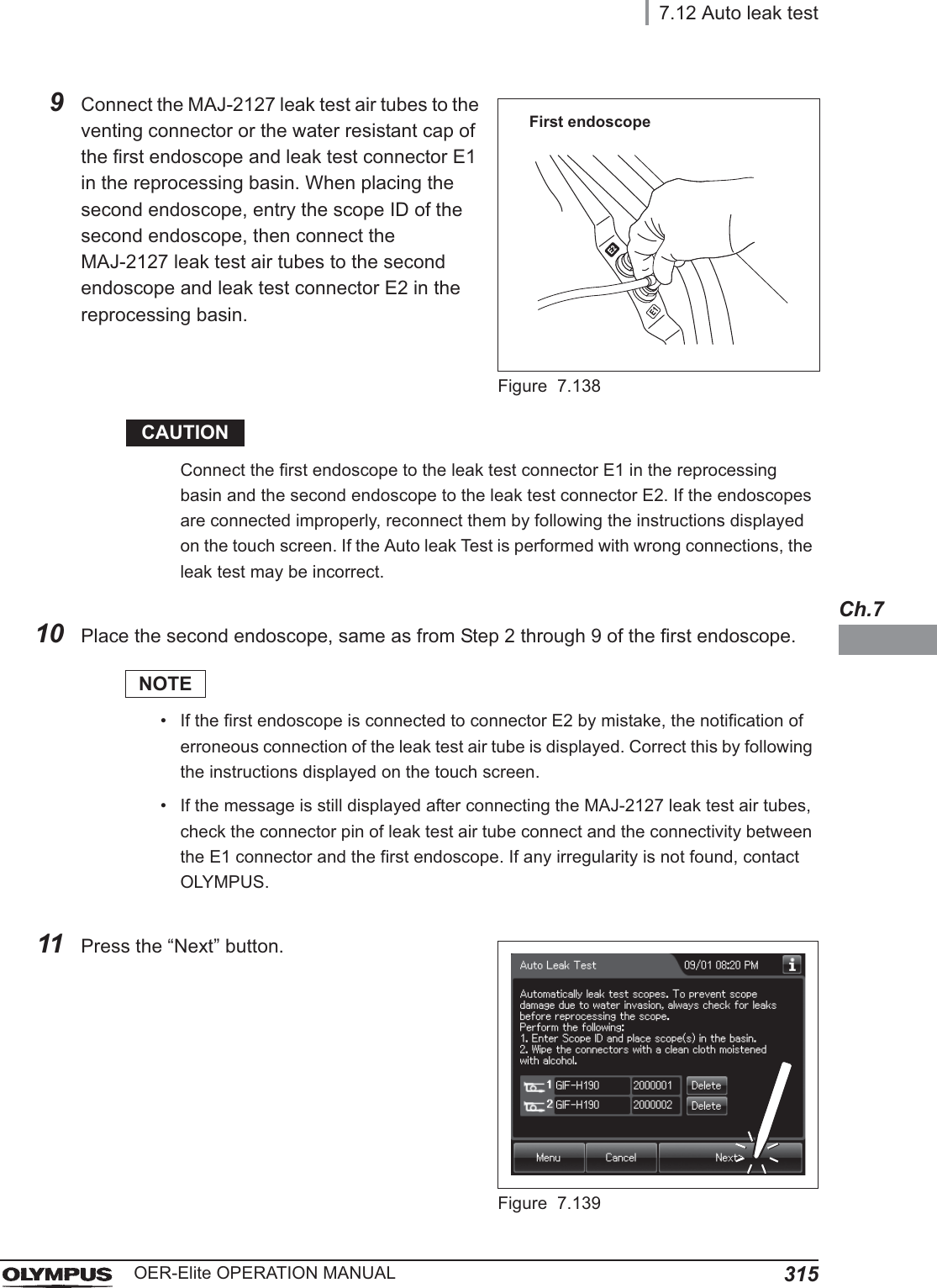
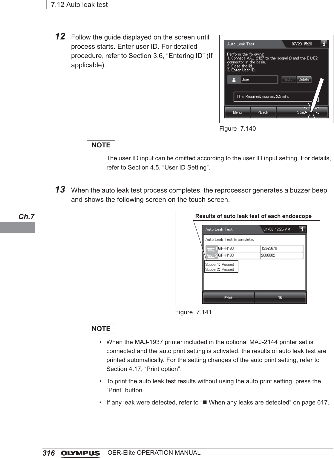
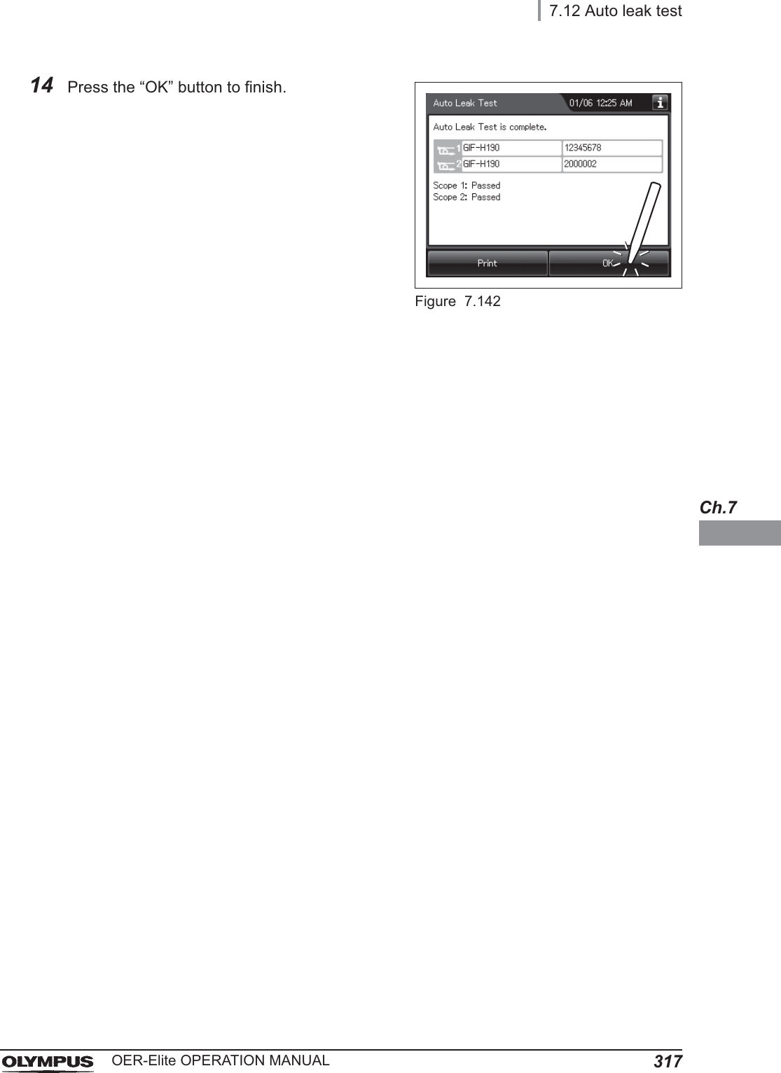
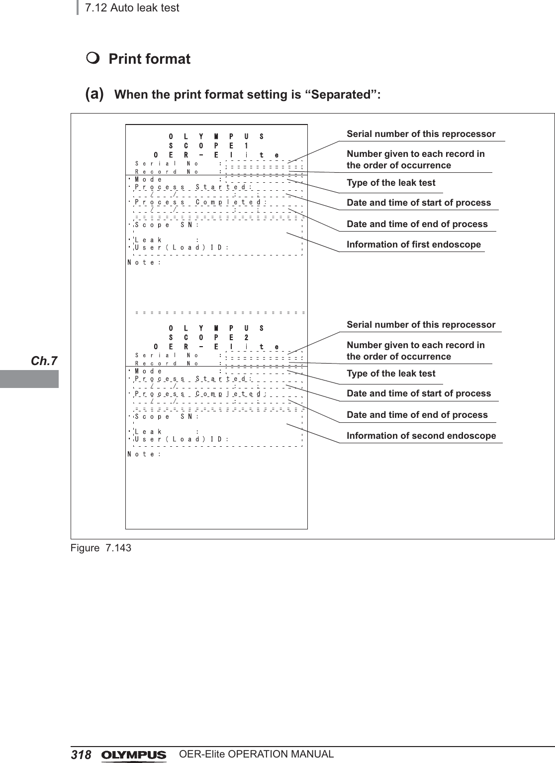
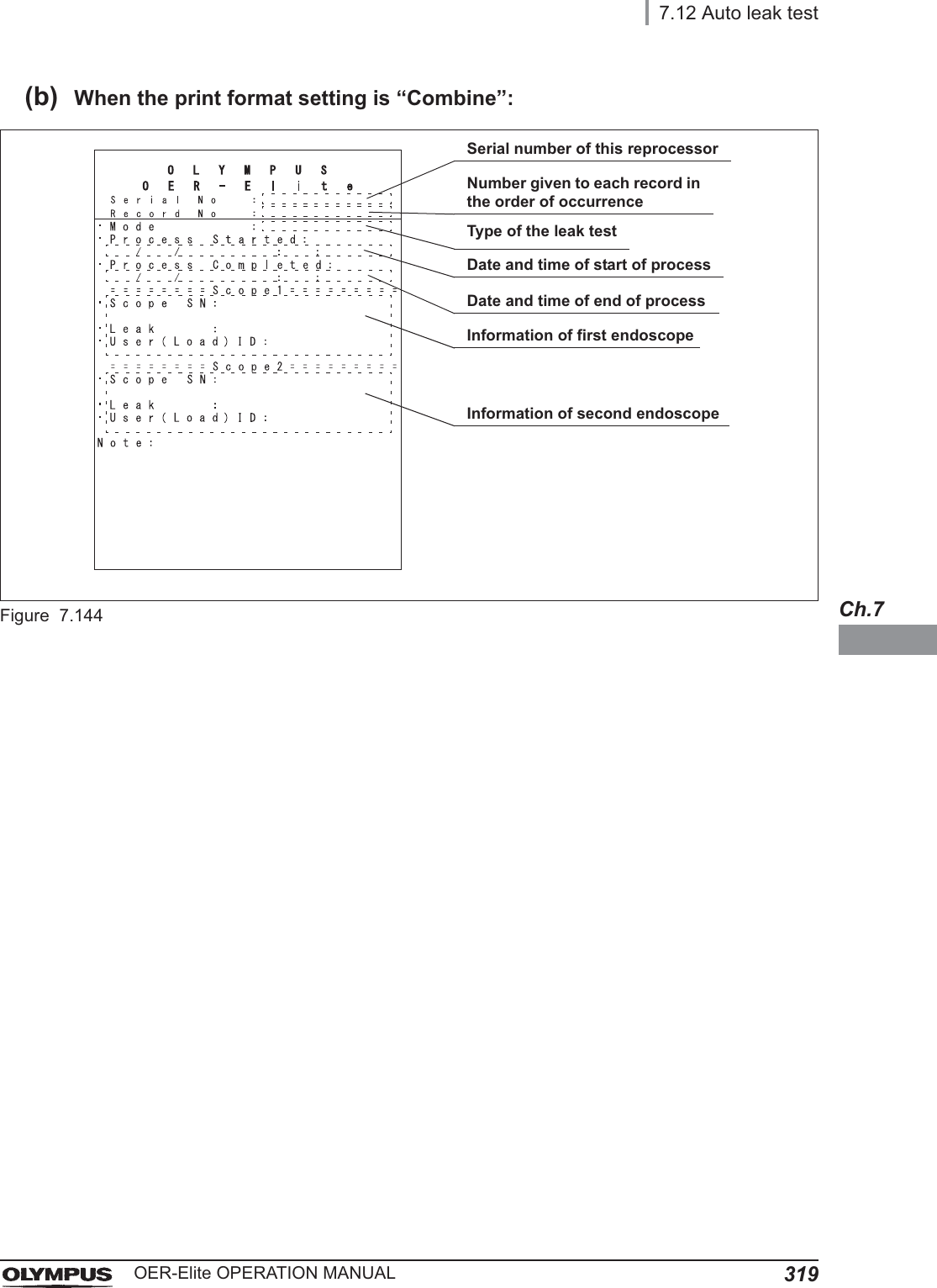
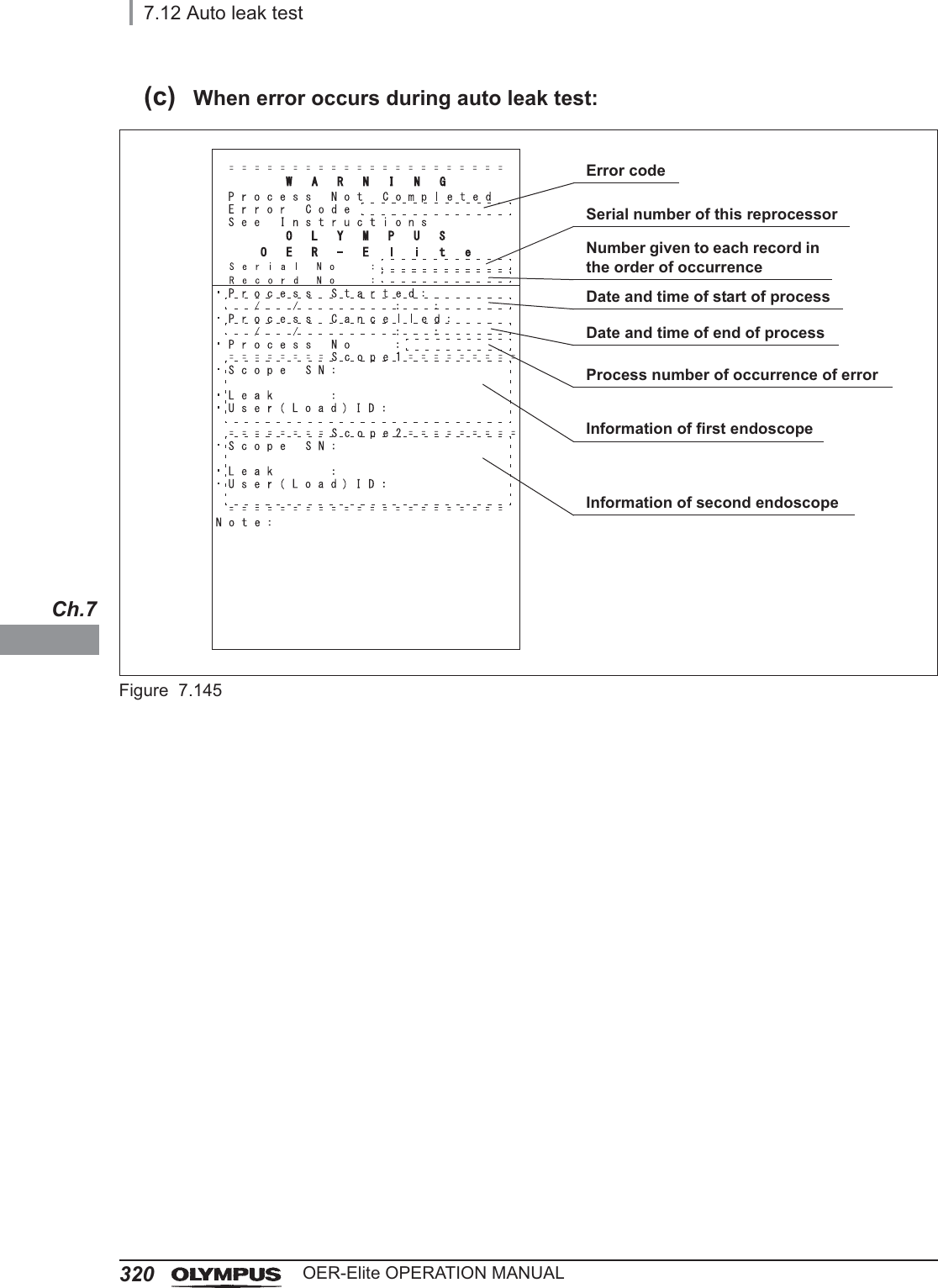
![7.12 Auto leak test311OER-Elite OPERATION MANUALCh.7CAUTION• If an irregularity is found with a leak test air tube, replace it with a new tube and retry the leak test.• When a leak test air tube is not to be used, disconnect it from the connector and be sure to remove it from the reprocessing basin. If reprocessing is performed without removing it, the leak test may be erroneous.• When the auto leak test gives a “Leaked” judgment to an endoscope do not execute reprocessing program [1] to [4] on the endoscope. Otherwise, water may penetrate inside the endoscope. The endoscope should be subjected to the leaking scope decontamination and then serviced. For details on the leaking scope decontamination, refer to Section 7.15, “Leaking scope decontamination”.• The leak test result may become “Leaked” depending on the temperature of the endoscope. To perform auto leak test with the ultrasonic endoscope, wait for more than 30 minutes. To perform it with the other type of endoscope, wait for more than 15 minutes. Then, re-execute the auto leak test. If the result is “Leaked” again, the scope should be subjected to the leaking scope decontamination and then serviced. For details on the leaking scope decontamination, refer to Section 7.15, “Leaking scope decontamination”.NOTE• The covering of the bending section of the endoscope may dilate slightly during the leak test. This is not malfunction.• The auto leak test may sometimes be incapable of detecting a very small hole.](https://usermanual.wiki/Olympus-Medical-Systems/RU2020.Operation-Manual-3/User-Guide-3575683-Page-45.png)
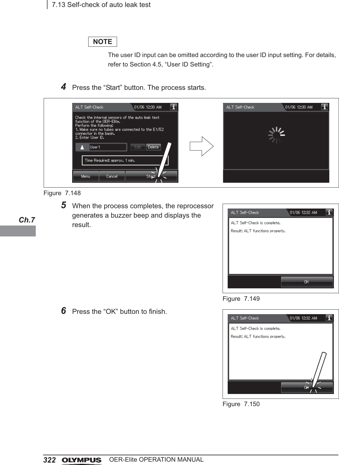
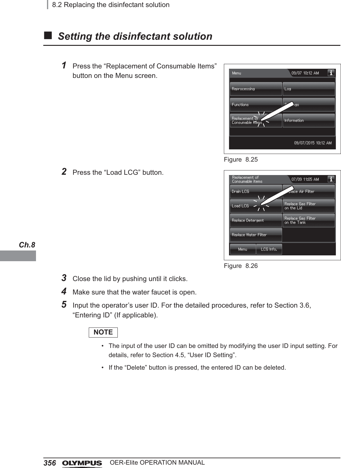
![7.13 Self-check of auto leak test321OER-Elite OPERATION MANUALCh.7This function is checked the operation of the auto leak test function.The self-check of auto leak function is performed automatically during the load LCG process. However, if the load LCG process stops and an error code ([E112], etc.) is generated, execute the Self-check of auto leak test.CAUTIONDo not connect any leak test air tubes to leak test connectors E1 or E2 on the reprocessing basin. Otherwise, the self-check will not run properly and Auto Leak Test function will not work properly.7.13 Self-check of auto leak test1Press the “Functions” button on the Menu screen.Figure 7.1462Press the “ALT Self-Check” button on the 2nd page of the Function menu.Figure 7.1473Input the operator’s user ID. For the detailed procedure, refer to Section 3.6, “Entering ID” (If applicable).](https://usermanual.wiki/Olympus-Medical-Systems/RU2020.Operation-Manual-3/User-Guide-3575683-Page-55.png)
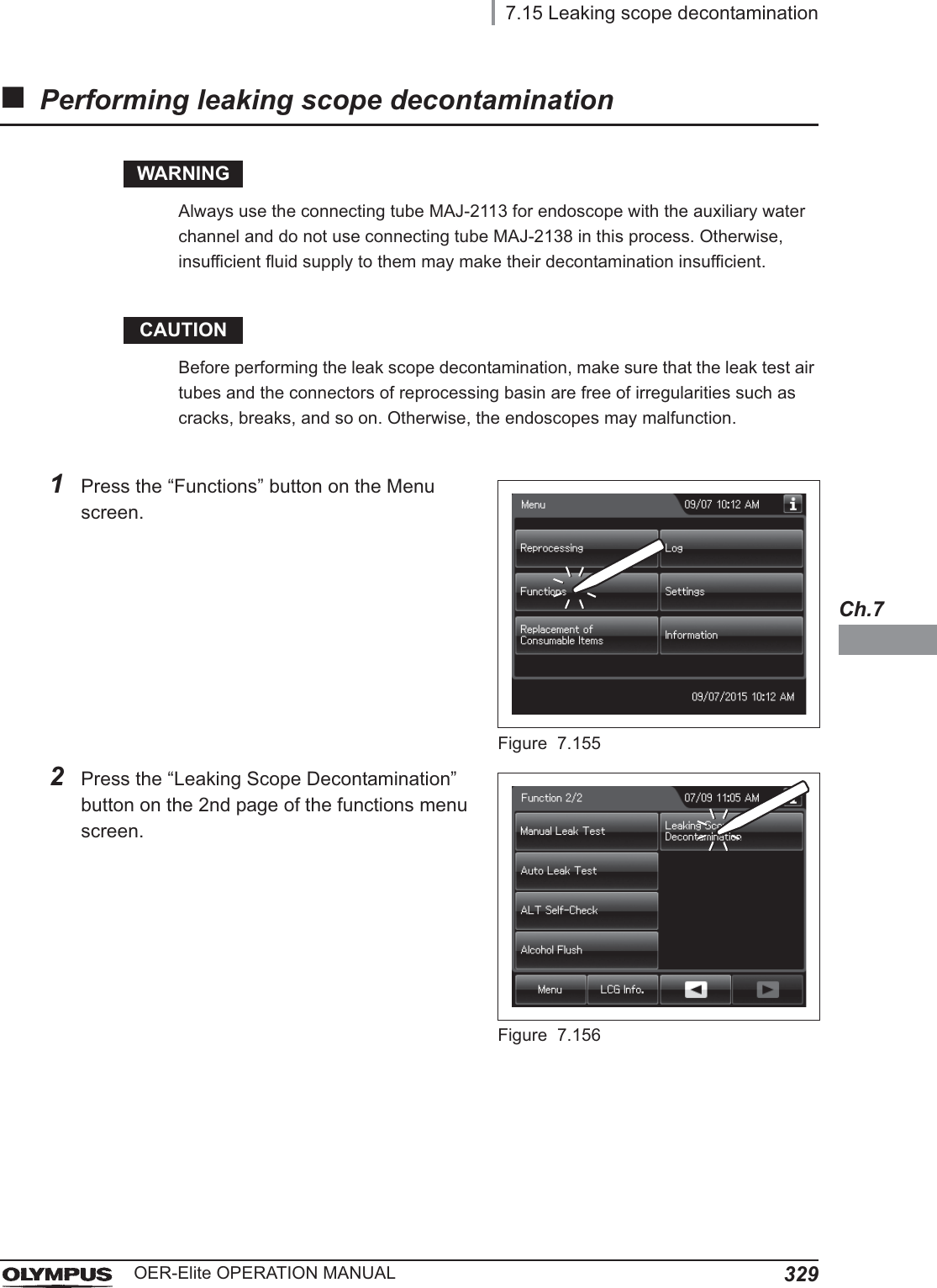
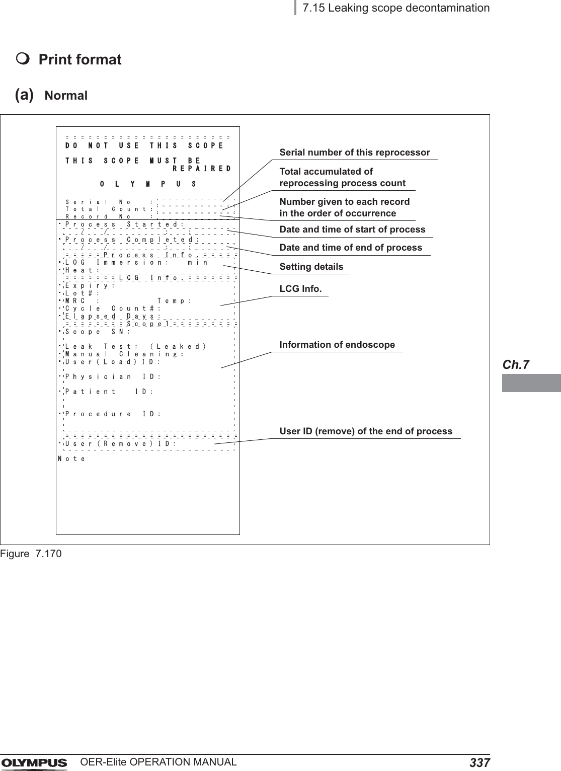
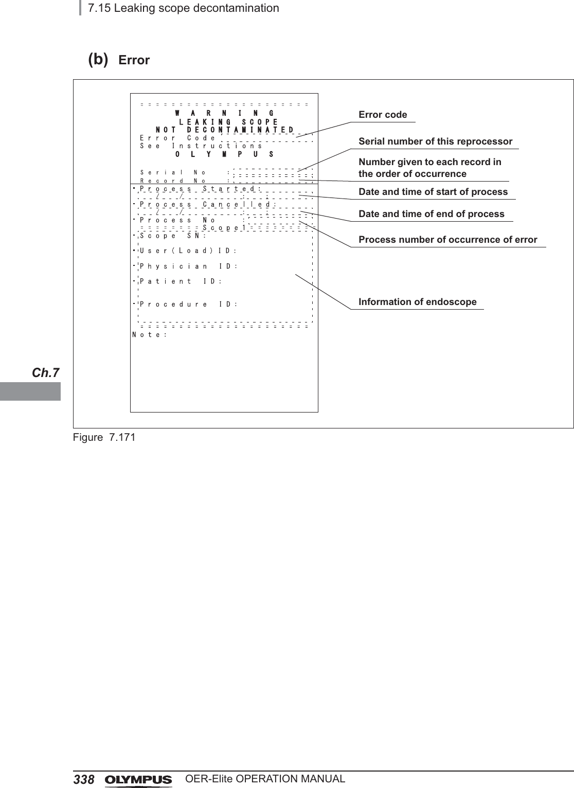
![3267.15 Leaking scope decontaminationOER-Elite OPERATION MANUALCh.7If water leak of endoscope is detected in a leak test before manual cleaning or an auto leak test before reprocessing, apply leaking scope decontamination for the endoscope before sending it for servicing center. By using this function the endoscope can be immersed in the disinfectant solution while preventing from influx of disinfectant solution into the internal of the endoscope.In case error code [E115] is displayed during the auto leak test process, perform the manual leak test and confirm area(s) of the leaking point(s). If a leaking point is found, thoroughly dry the identified location of the leak on the outer area of the endoscope using alcohol and a clean lint-free cloth. Carefully apply a piece of electrical tape or other waterproof tape over the location of the leak prior to immersing the endoscope in detergent solution. Wrapping the tape too tightly may result in damage to the endoscope. Then perform the Leaking scope decontamination with the endoscope. If error code [E115] is generated again in Leaking scope decontamination, the leaking point cannot be stopped by taping, or a leaking point is not found, do not perform this process but contact Olympus. For details, refer to “Manual decontamination for leaking endoscope” on page 619.WARNING• The leaking scope decontamination process is intended to decontaminate a leaking endoscope before sending it to a servicing center. It does not guarantee the reprocessing of the endoscope and its accessories after this process. After completing this process, do not use the endoscope and its accessories in examination but send it to a servicing center.• Do not subject an endoscope without leak (correctly functioning endoscope) in this process.• Do not perform the Leaking scope decontamination process with auxiliary water tubes. This process is not capable of high-level disinfection of the auxiliary water tubes. Even when the auxiliary water tube cleaning setting is activated, do not use the MAJ-2138. Instead, be sure to use the provided MAJ-2113. Otherwise, the reprocessing of the auxiliary water tubes may be insufficient.• When handling the disinfectant solution, wear personal protective equipment to prevent any disinfectant solution from getting on your skin and eyes or being inhaled. Avoid direct physical contact and inhalation of vapors. If any disinfectant solution gets in your eyes, immediately rinse with a large amount of fresh water and then consult a medical specialist. Wear personal protective equipment, such as eyewear, face mask, moisture-resistant clothing, and chemical-resistant gloves that fit properly and are long enough so that your skin and eyes is not exposed. All personal protective equipment should be inspected before use and replaced periodically.7.15 Leaking scope decontamination](https://usermanual.wiki/Olympus-Medical-Systems/RU2020.Operation-Manual-3/User-Guide-3575683-Page-60.png)
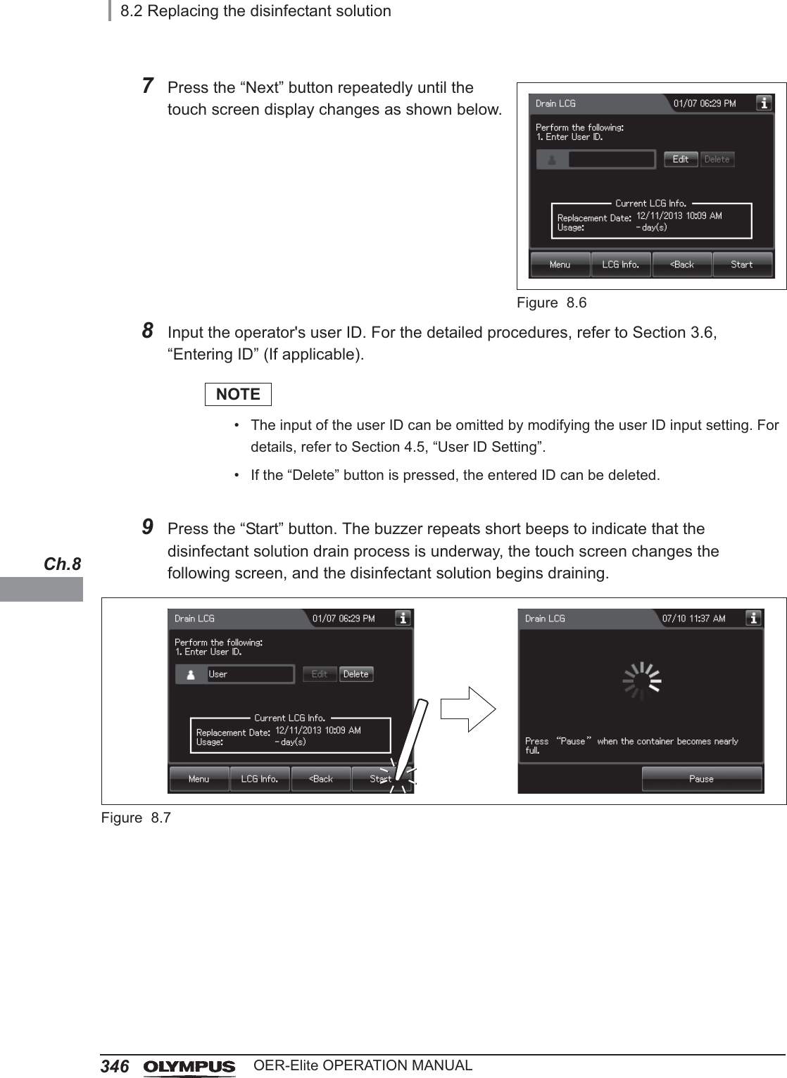
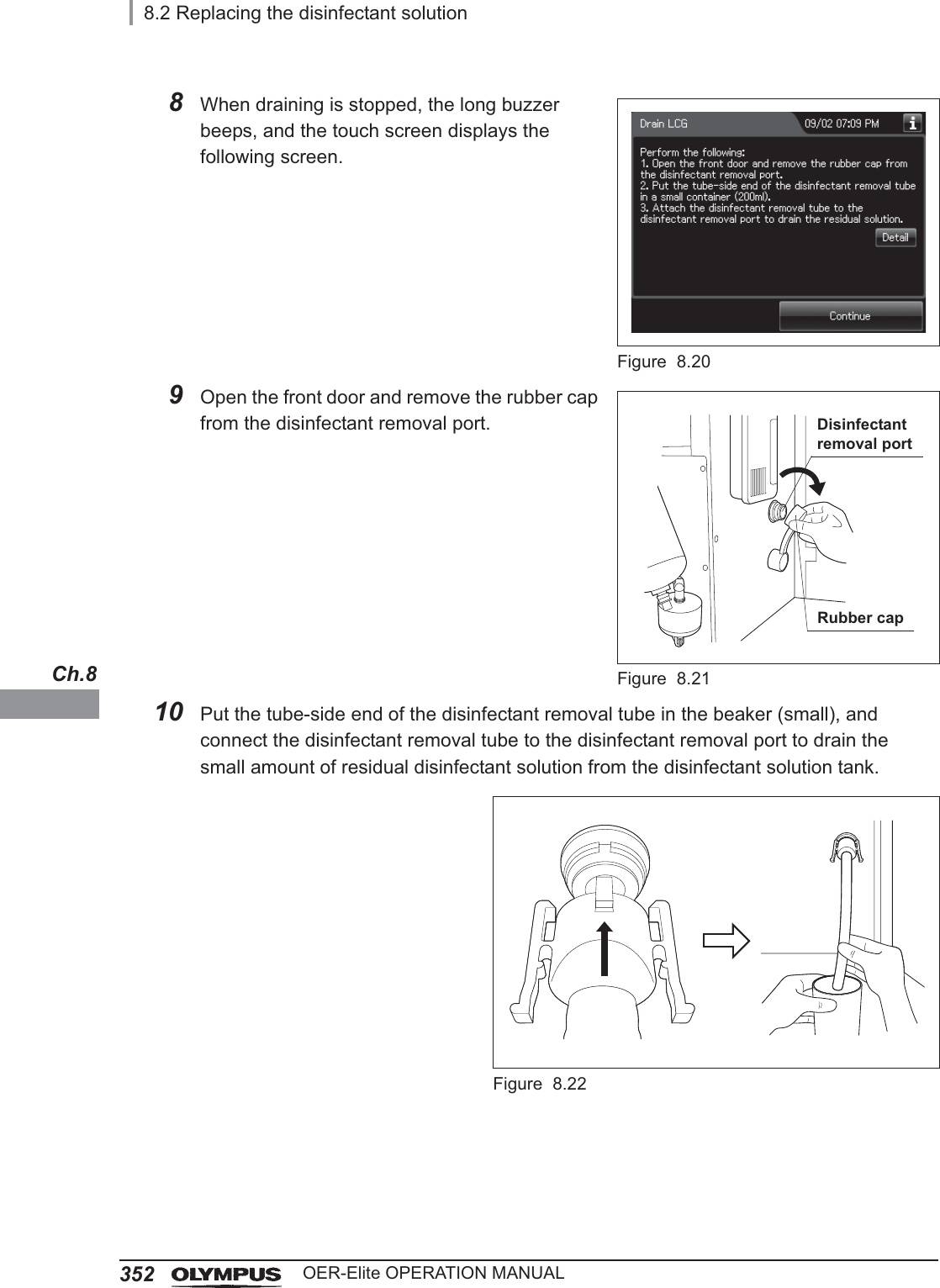
![8.2 Replacing the disinfectant solution345OER-Elite OPERATION MANUALCh.85While pulling the sleeve on the connector of the disinfectant collection hose, connect the connector into the disinfectant solution nozzle inside the reprocessing basin. After connection, pull the hose gently to make sure it is properly attached.Figure 8.4WARNINGBe sure to attach the disinfectant solution nozzle cap to the original position. Otherwise, the disinfectant solution will spatter.NOTE• If “DRAIN LCG” is selected and the FUNC START button is pressed without connecting the disinfectant collection hose, the buzzer repeats short beeps, disinfectant solution will fill the reprocessing basin and error code [E72] is displayed. In this case, treat it by following the procedure in Section 13.2, “Troubleshooting guide”.• Make sure that the disinfectant collection hose is not kinked and the end of hose in container is not clogged. Otherwise, the disinfectant solution will be spattered.6Put the other end of the disinfectant collection hose (the end without a connector) in a large container that can hold up to 24 liters.Figure 8.5](https://usermanual.wiki/Olympus-Medical-Systems/RU2020.Operation-Manual-3/User-Guide-3575683-Page-79.png)


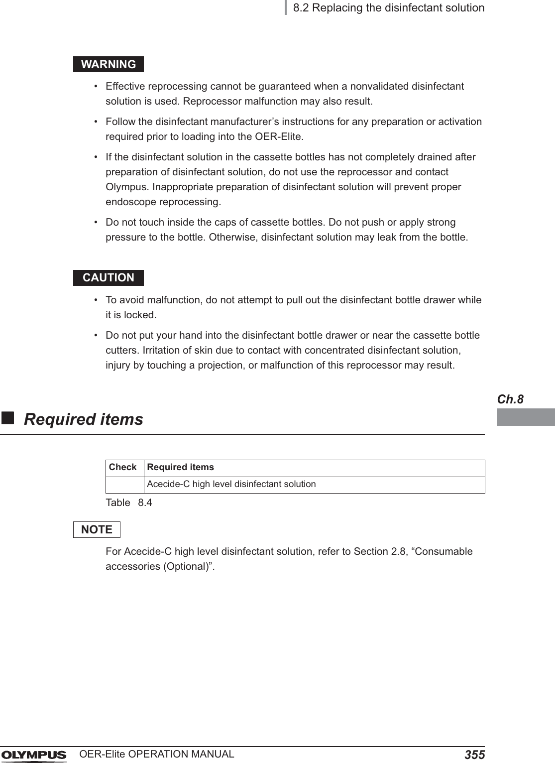
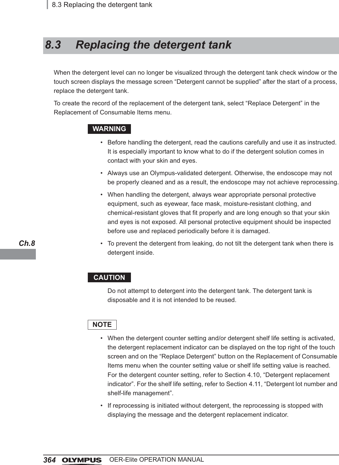
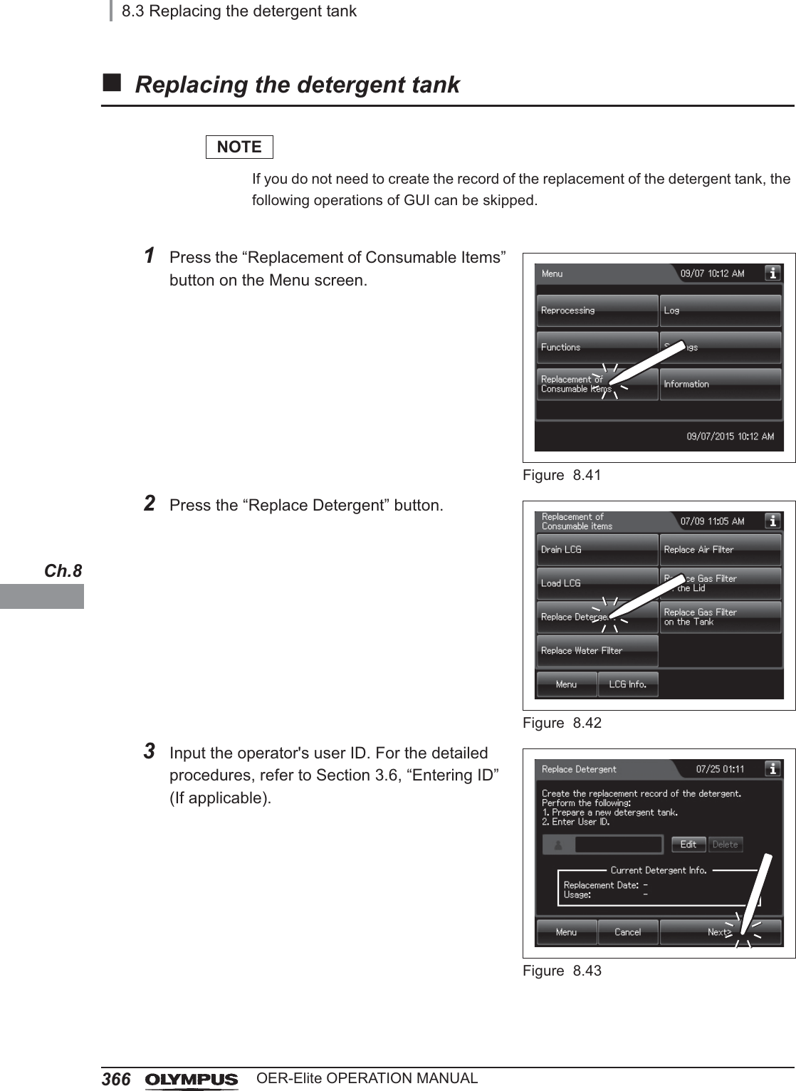
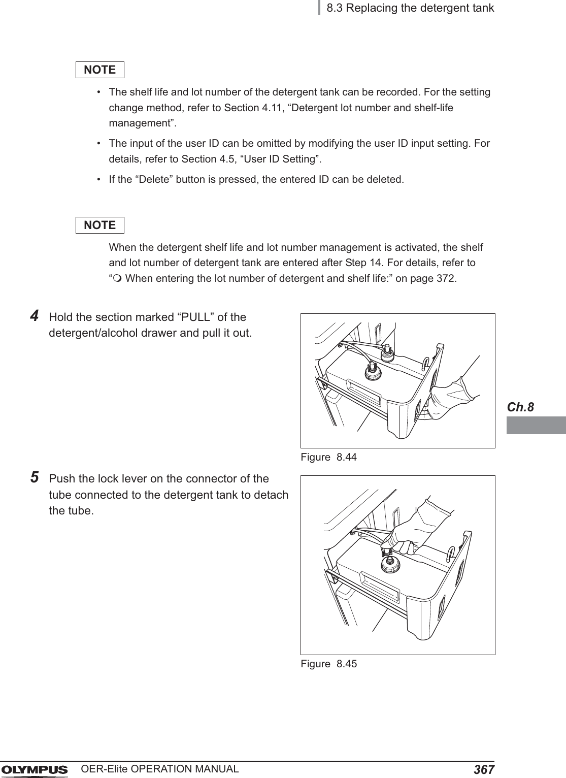
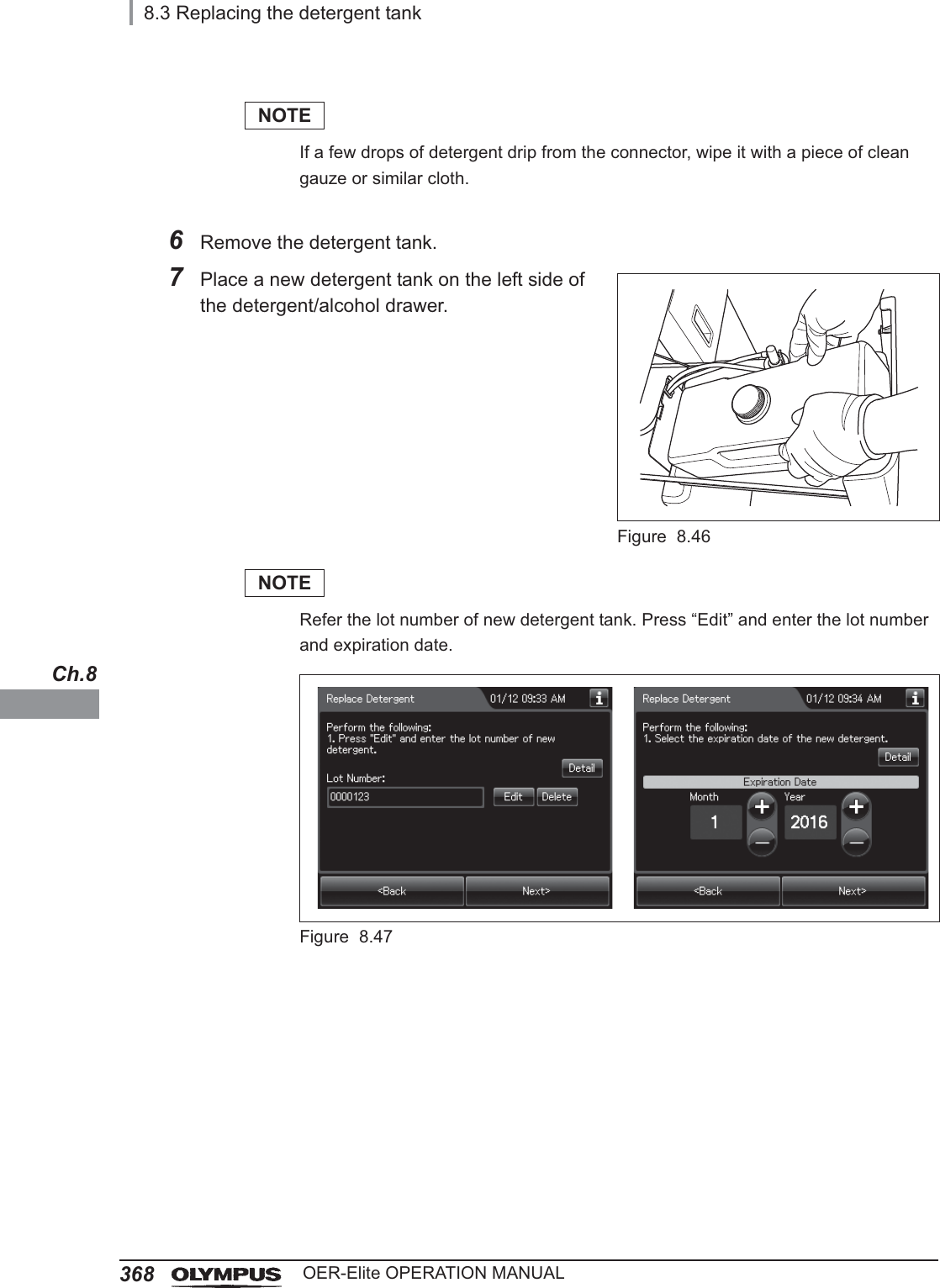
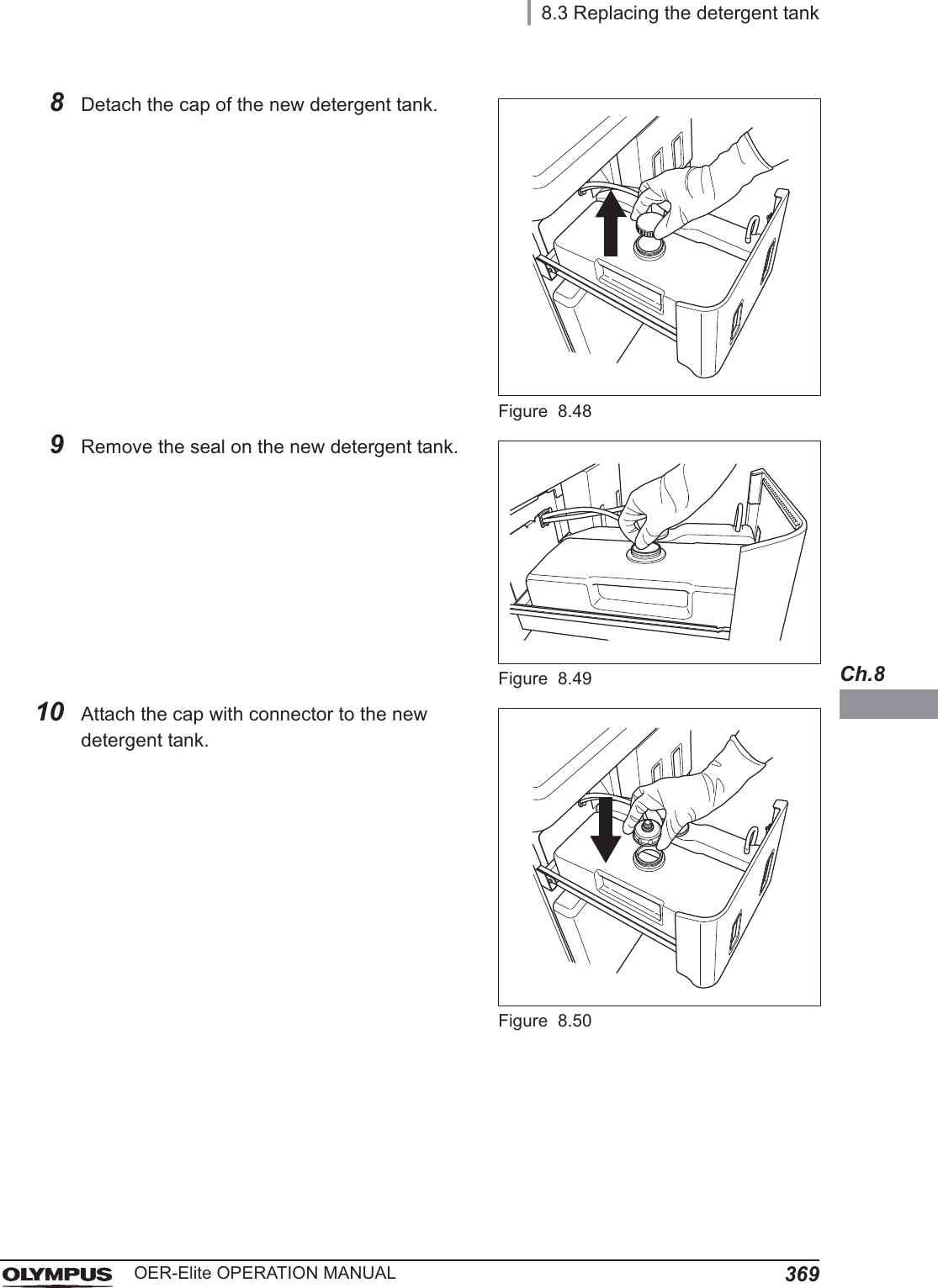
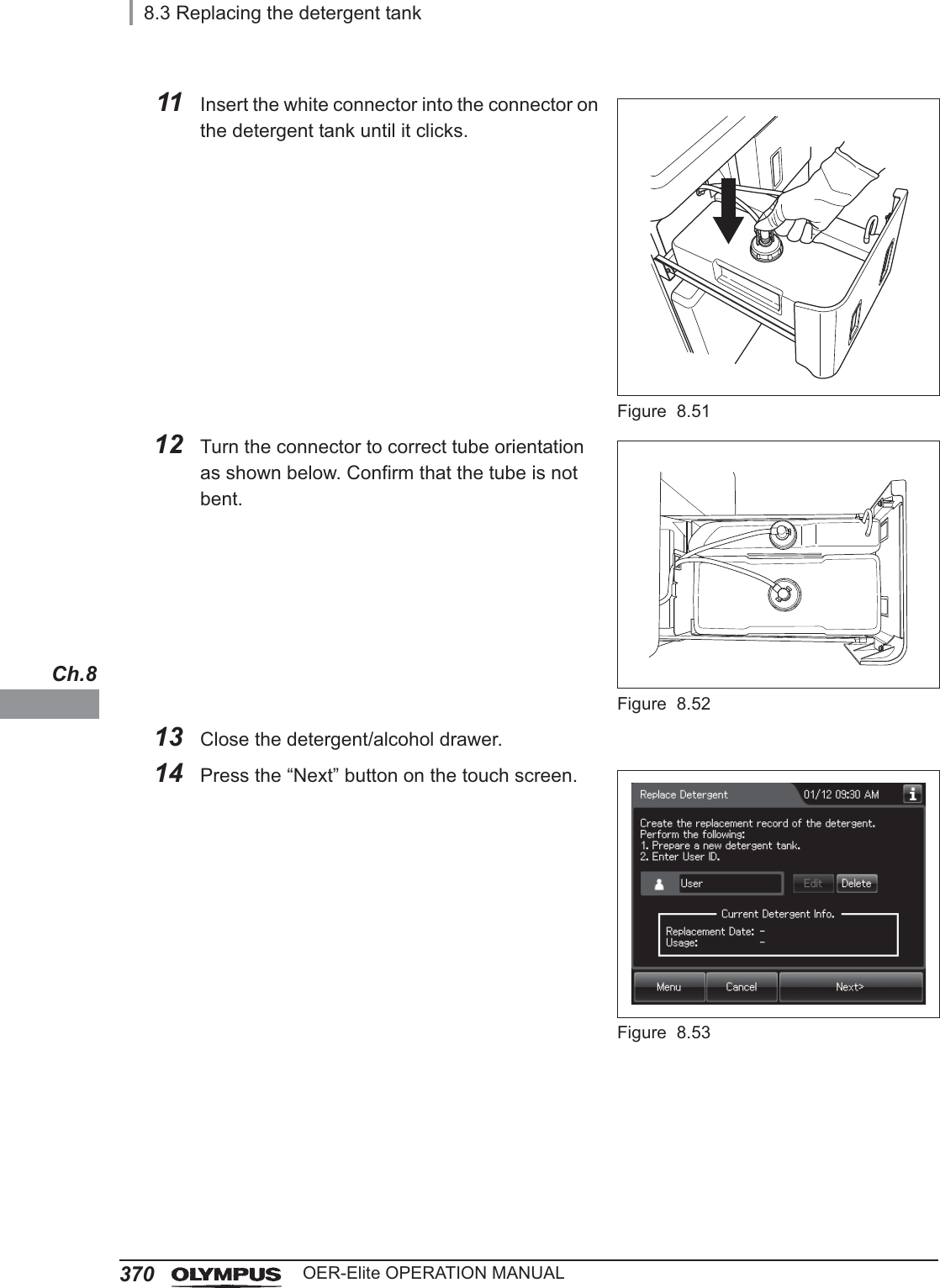
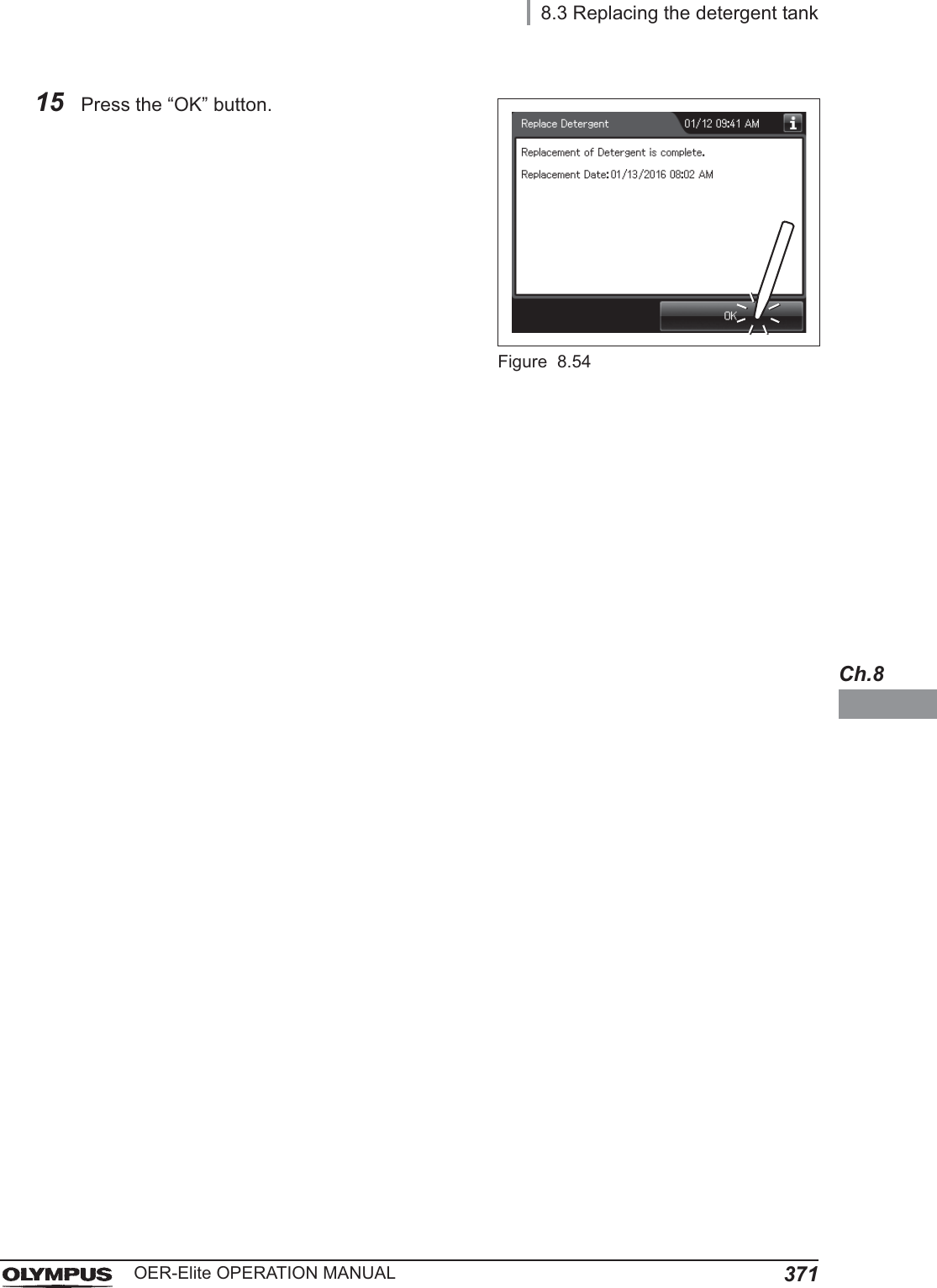
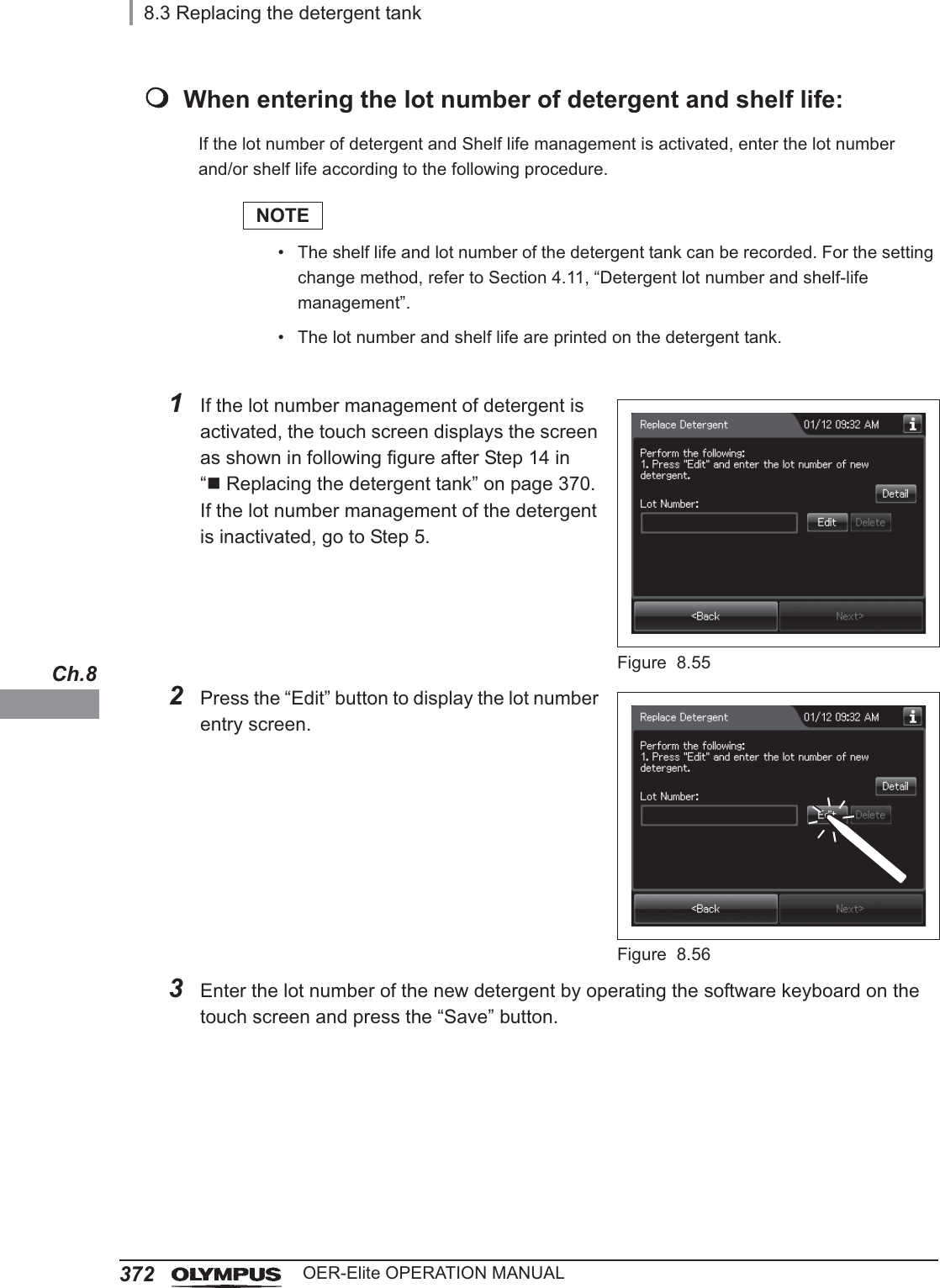
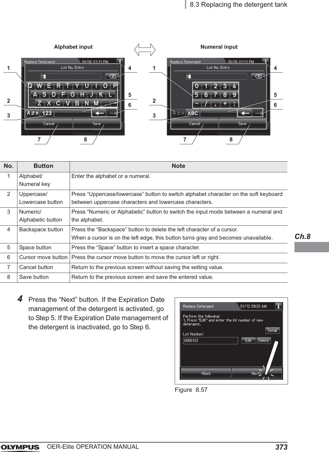
![8.3 Replacing the detergent tank365OER-Elite OPERATION MANUALCh.8NOTE• The detergent tank can hold about 2.8 L (95 ounces) of detergent (which can be used for approximately 30 reprocessing operations).• When reprocessing is performed with newly-installed reprocessor or with reprocessor after Section 9.9, “Preparing the reprocessor for long-term storage” is performed, reprocessing may stop with the message screen “Detergent cannot be supplied” even though there is enough detergent in the tank. To solve this problem, refer to Section 13.2, “Troubleshooting guide”, “Message, caution, and warning screens” on page 621.• The shelf life and lot number of the detergent tank can be recorded. For the setting change method, refer to Section 4.11, “Detergent lot number and shelf-life management”.• If reprocessing is initiated without detergent, error code [E095] is displayed and the reprocessing is stopped. The detergent replacement indicator on the main panel blinks.• When reprocessing is performed with newly-installed reprocessor or with reprocessor after Section 9.9, “Preparing the reprocessor for long-term storage” is performed, reprocessing may stop with error code [E095] displayed even though there is enough detergent in the tank. Refer to “When the “Message 093” is displayed” on page 635 to solve this problem.Required itemTable 8 . 5NOTEFor Olympus-validated detergent, refer to Section 2.8, “Consumable accessories (Optional)”.Check Required itemsOlympus-validated detergentClean gauze or similar cloth.](https://usermanual.wiki/Olympus-Medical-Systems/RU2020.Operation-Manual-3/User-Guide-3575683-Page-99.png)
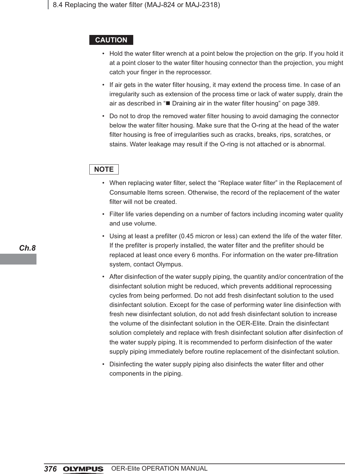
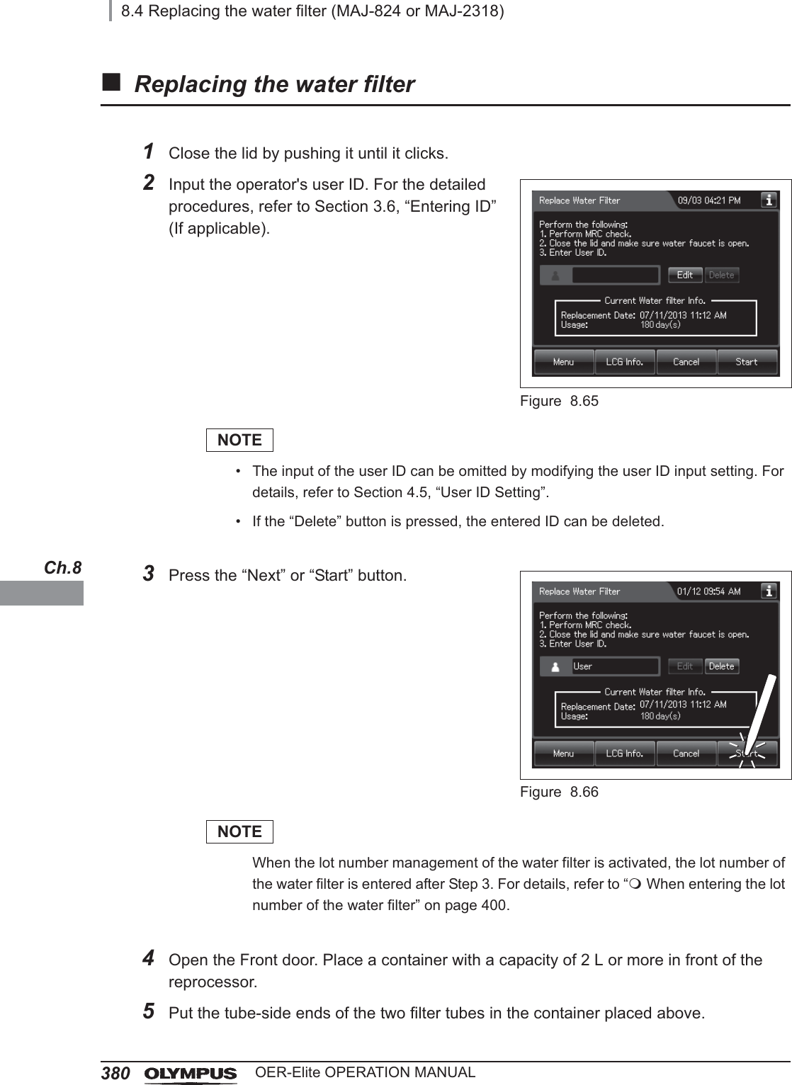
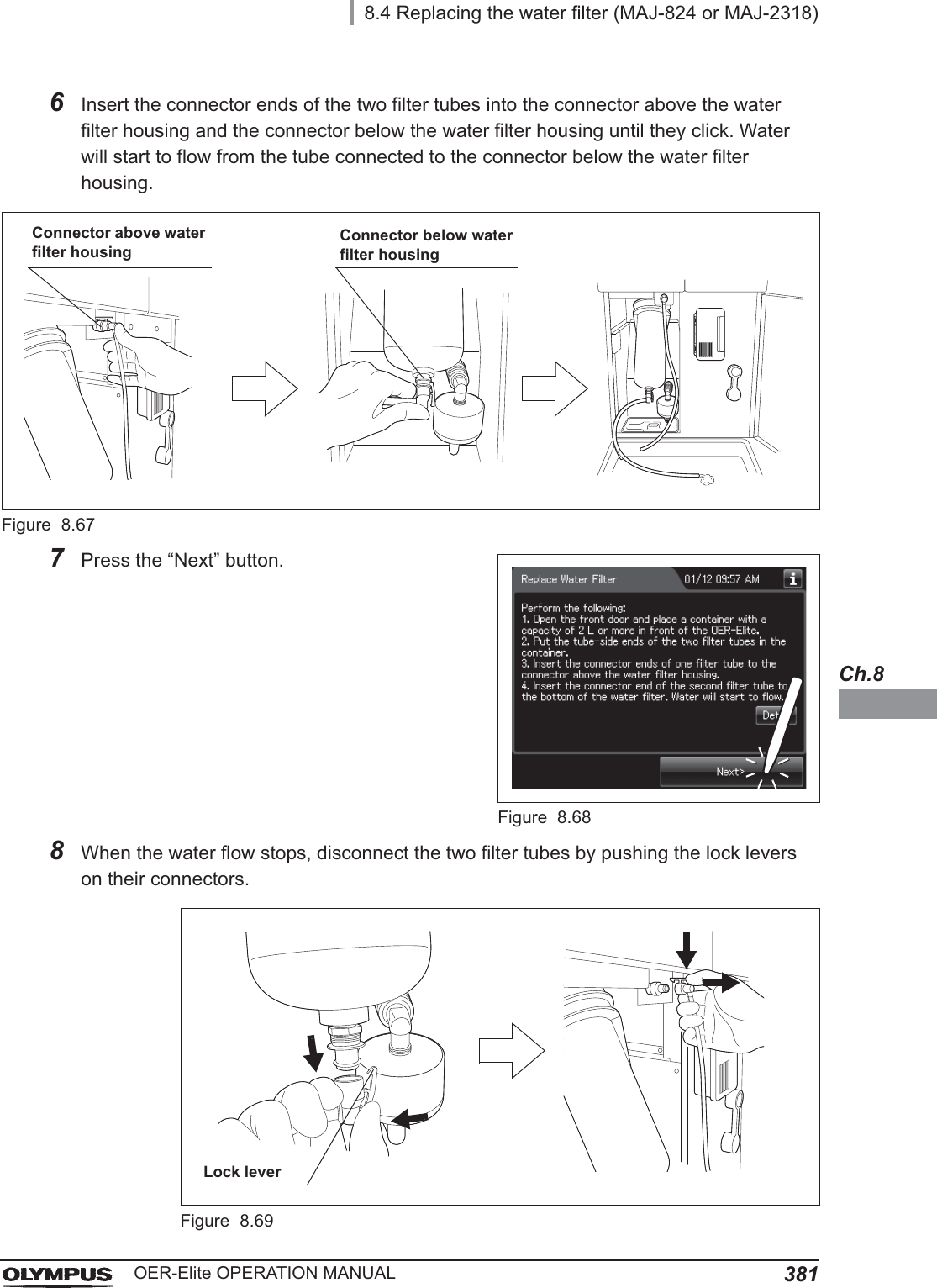
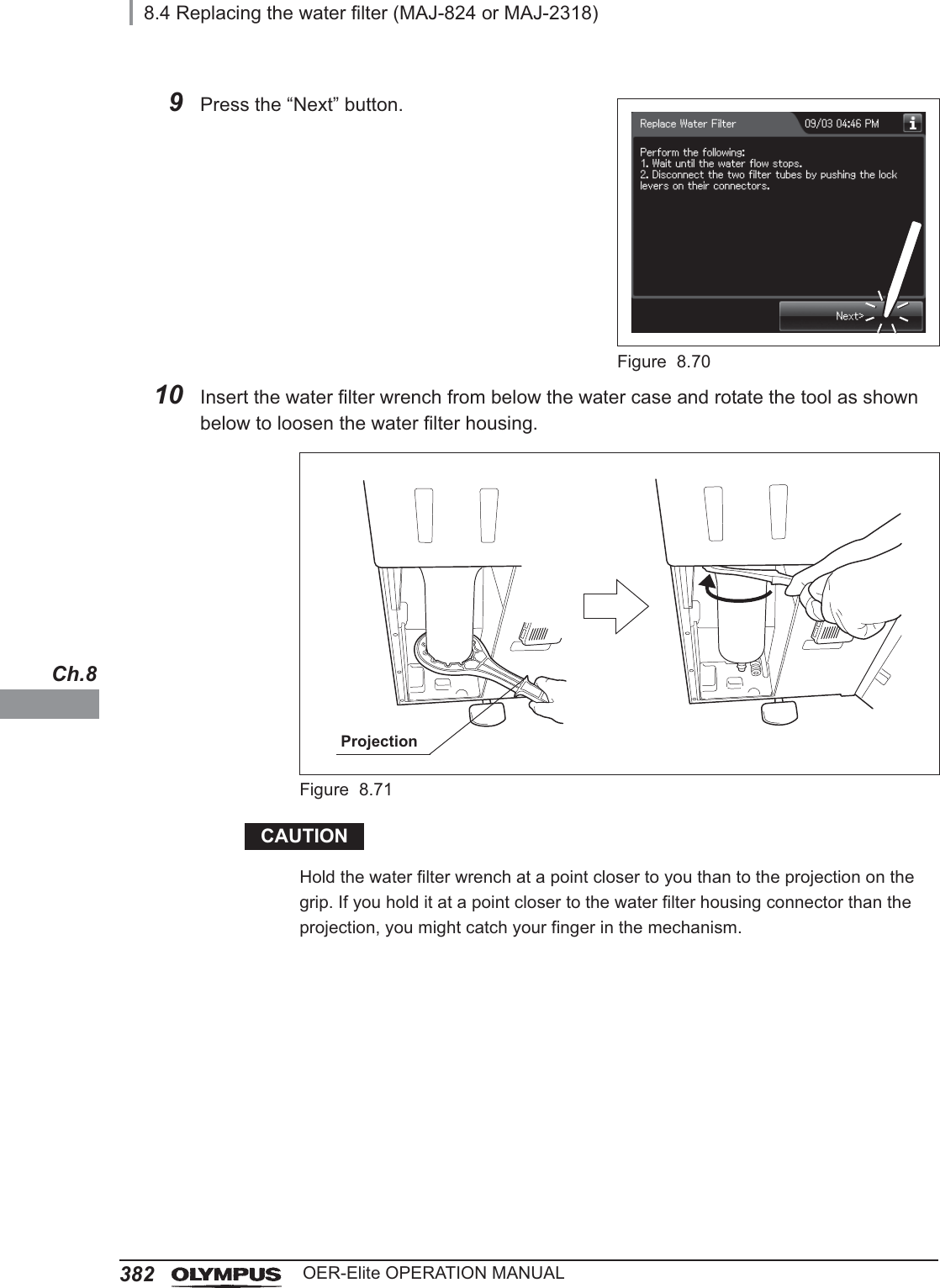
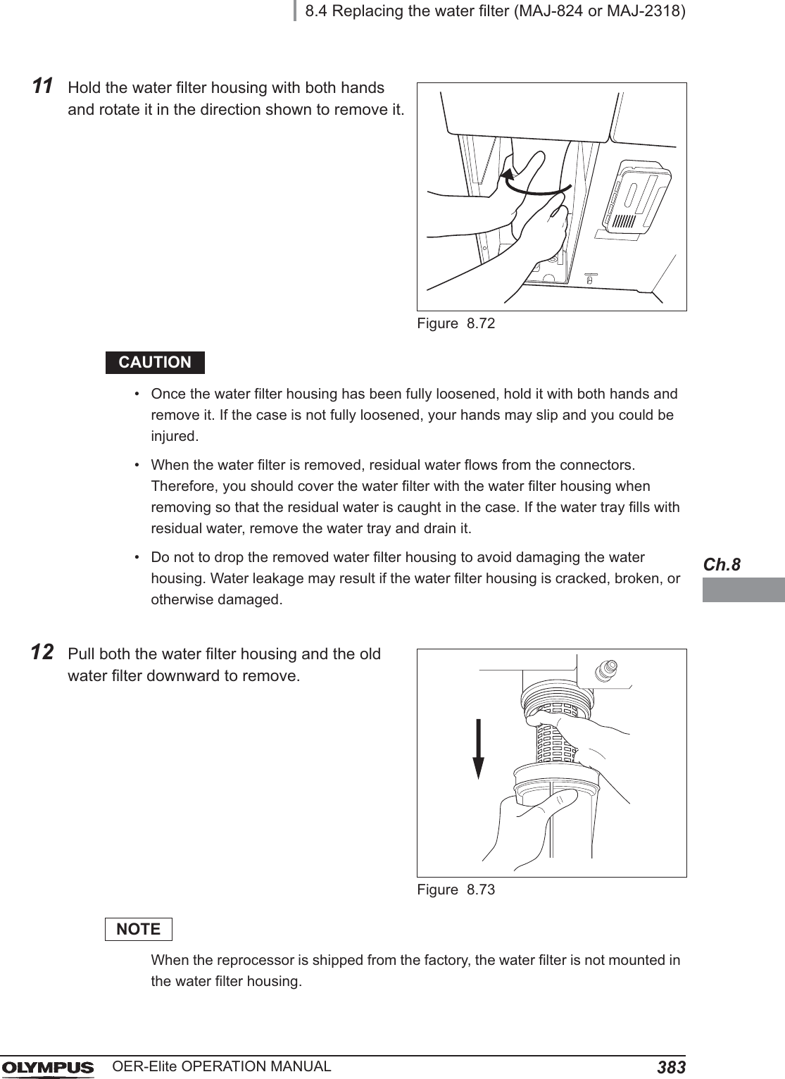
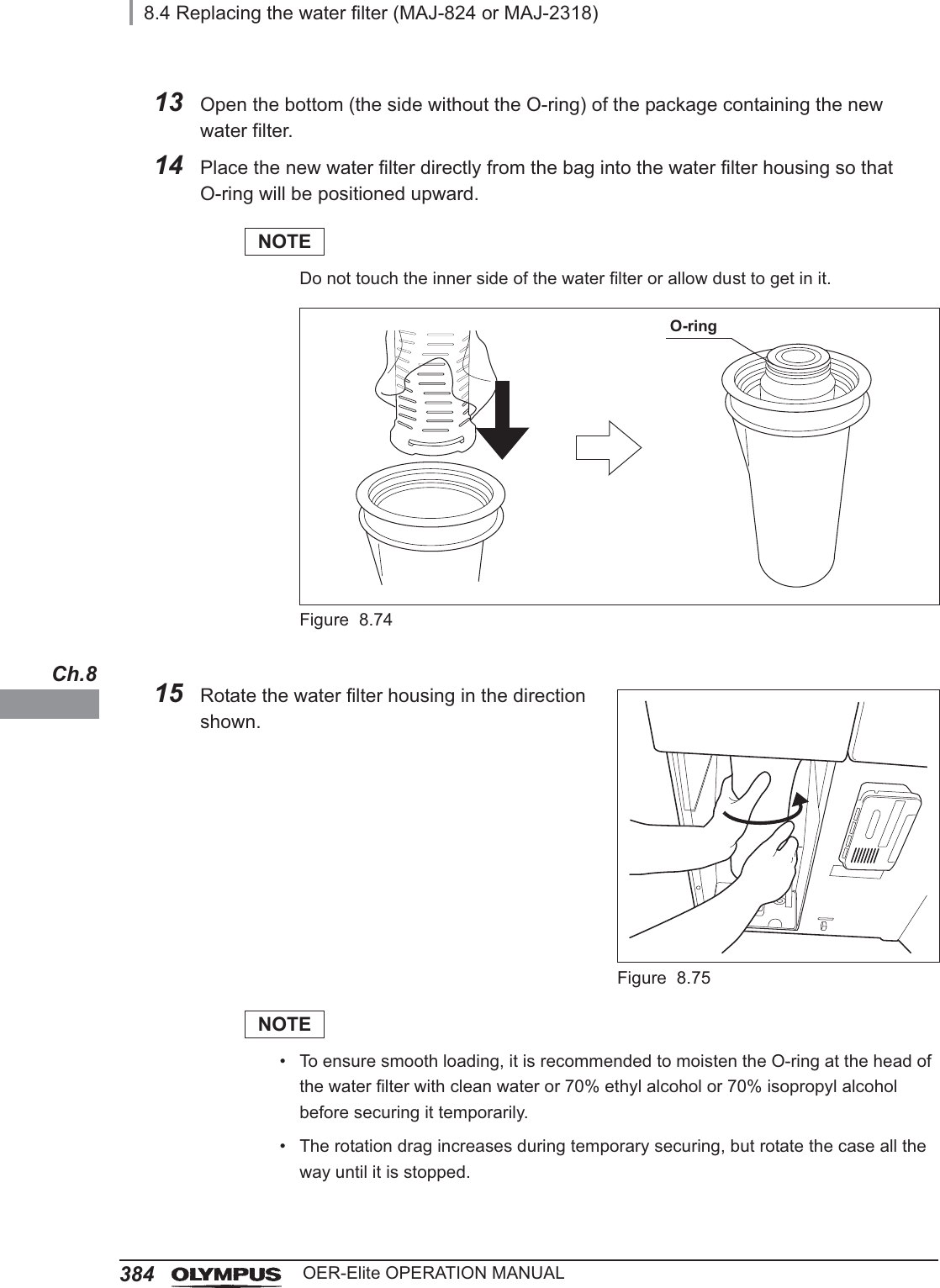
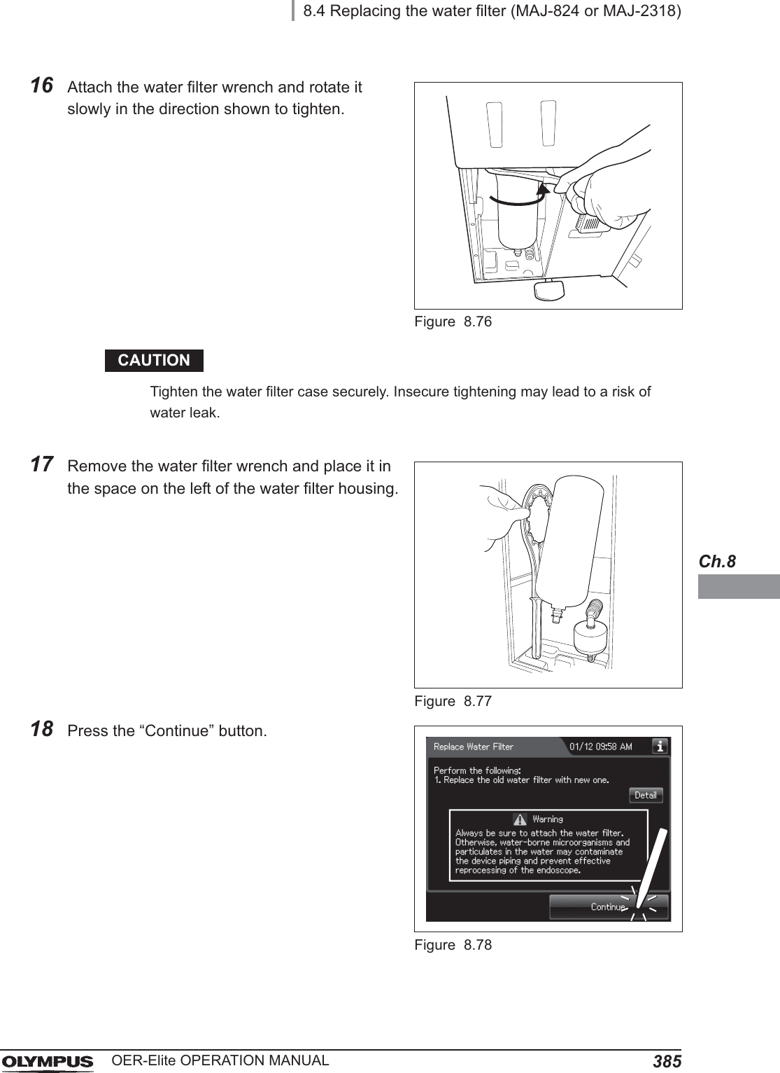
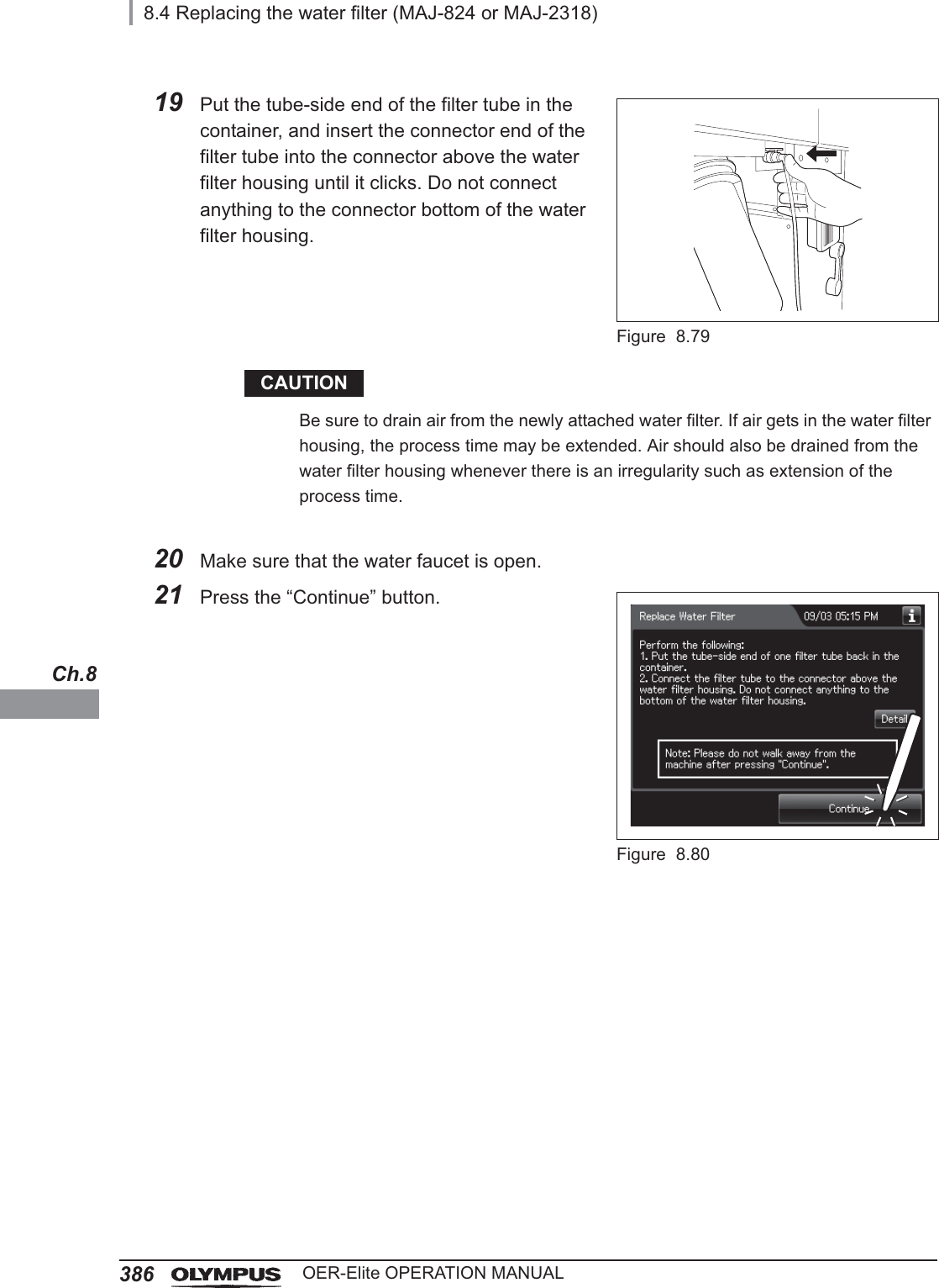
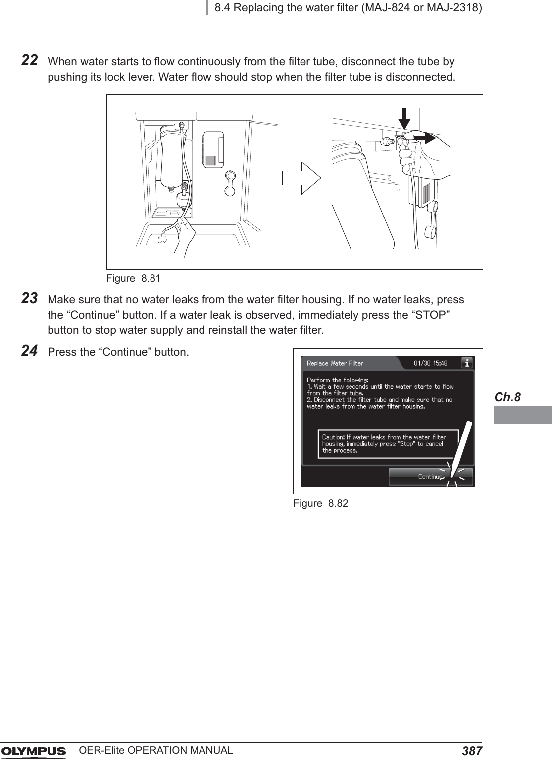
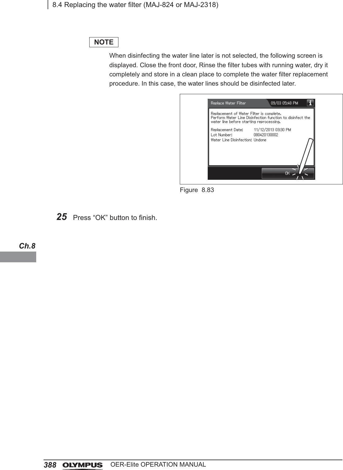
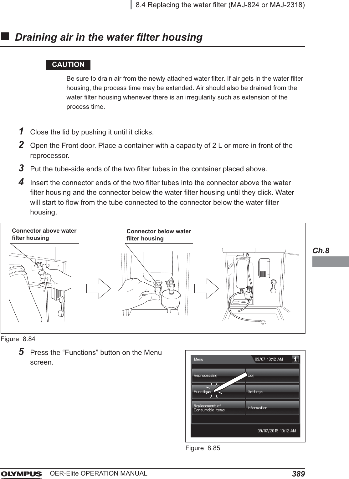
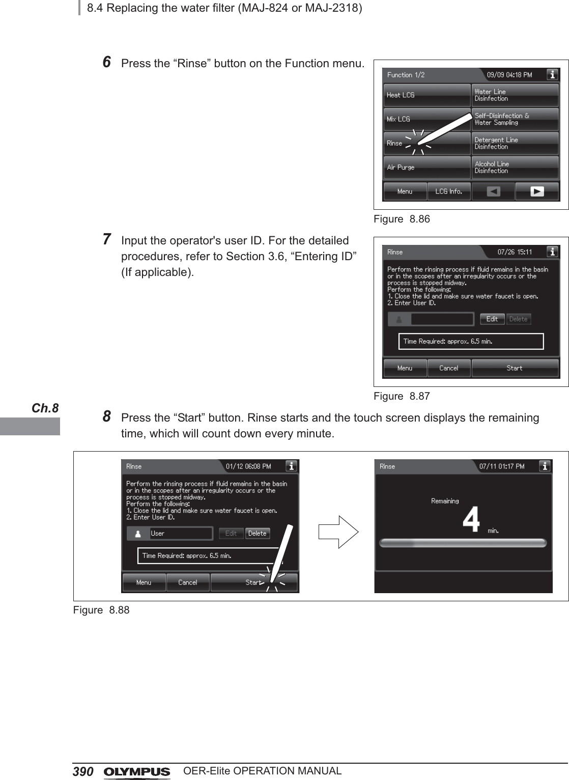
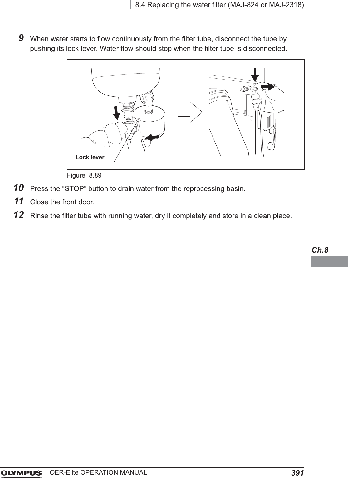
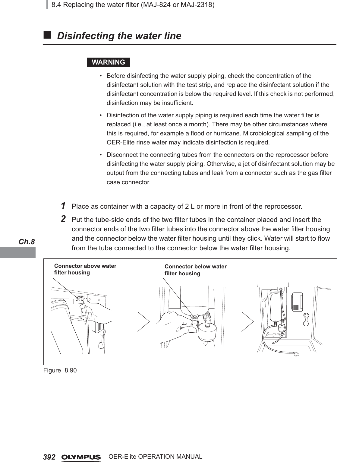
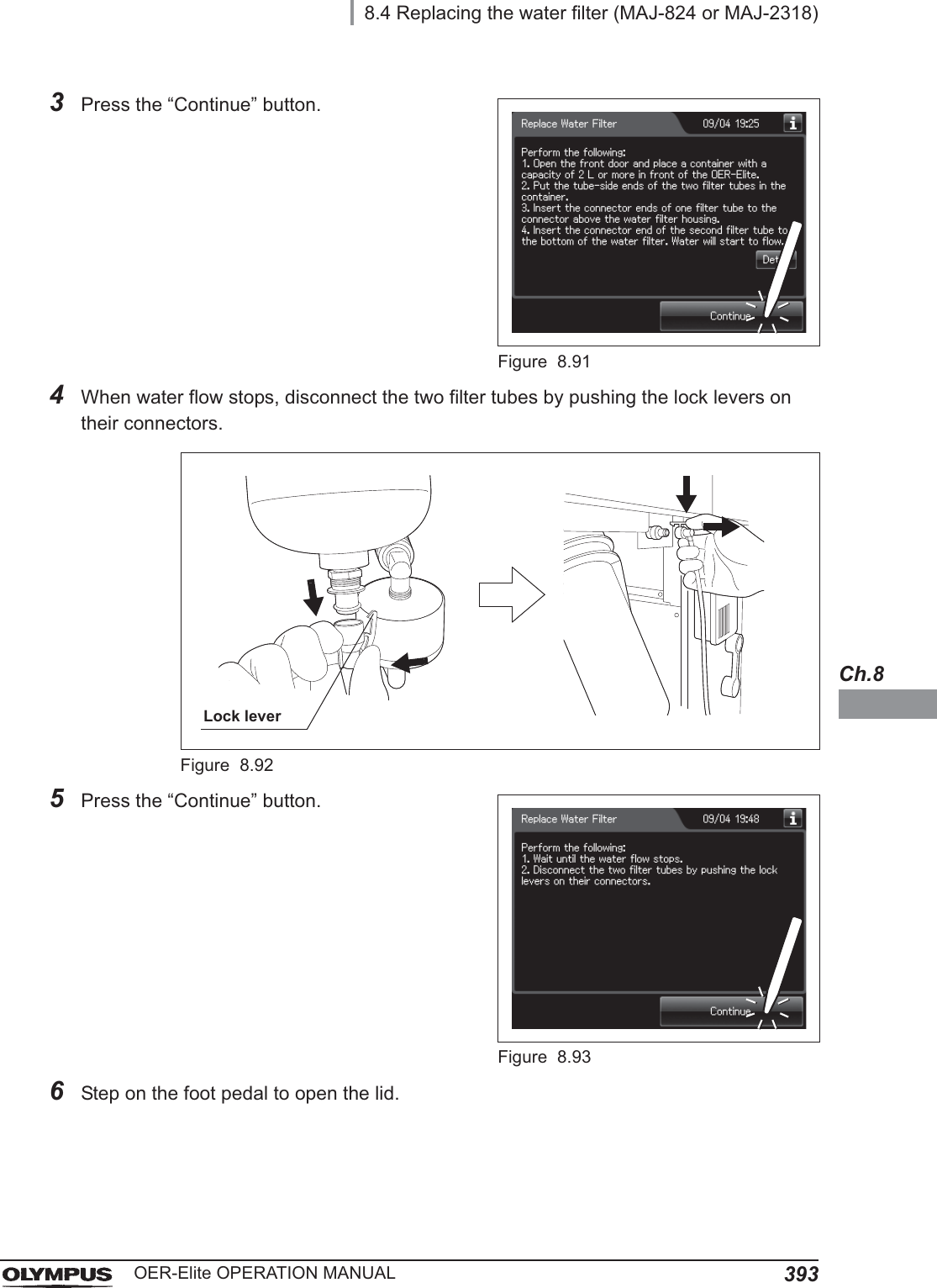
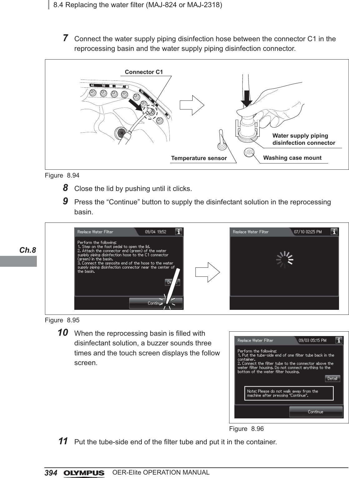
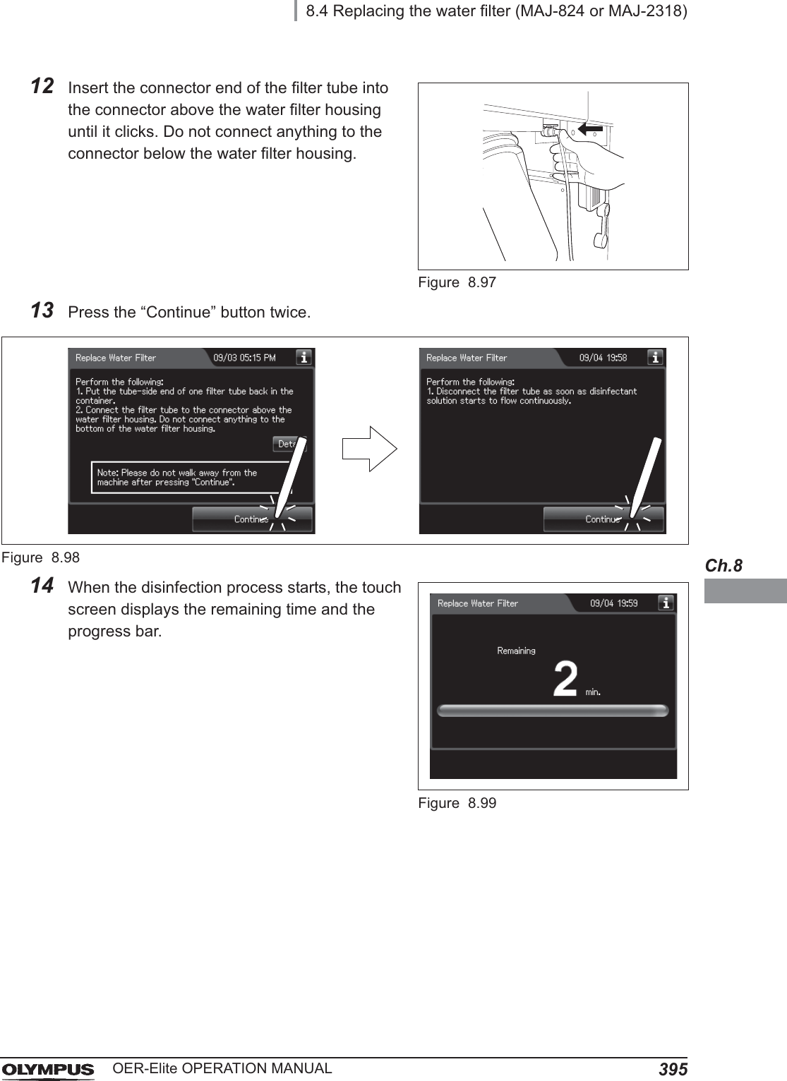
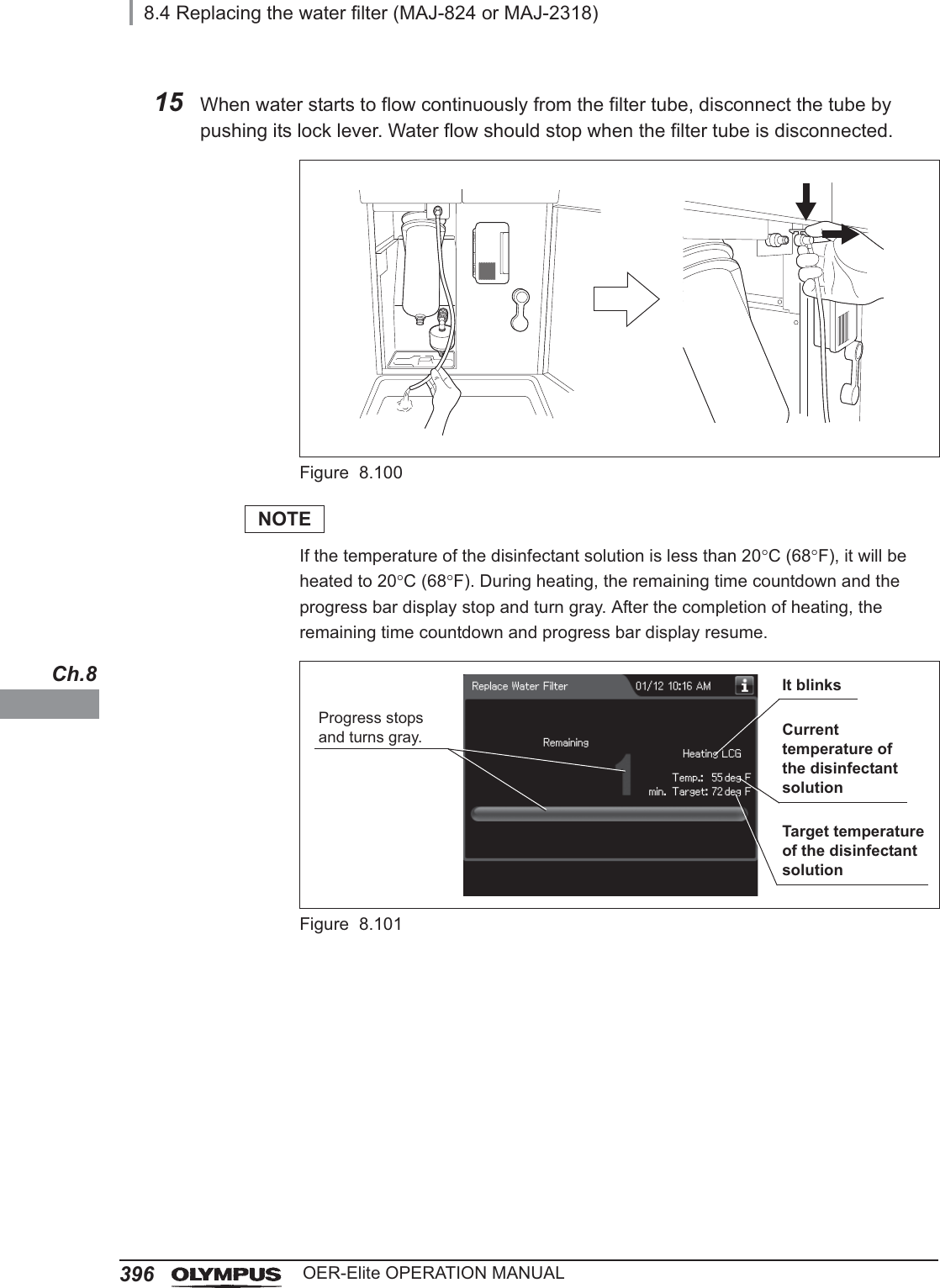
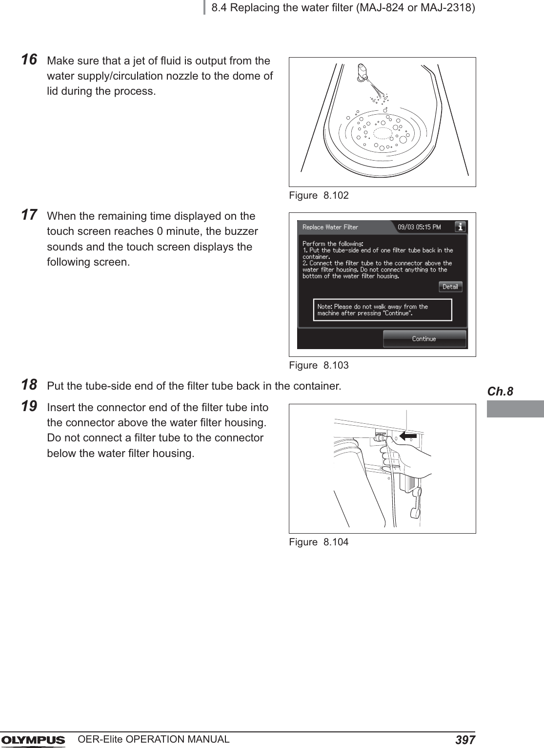
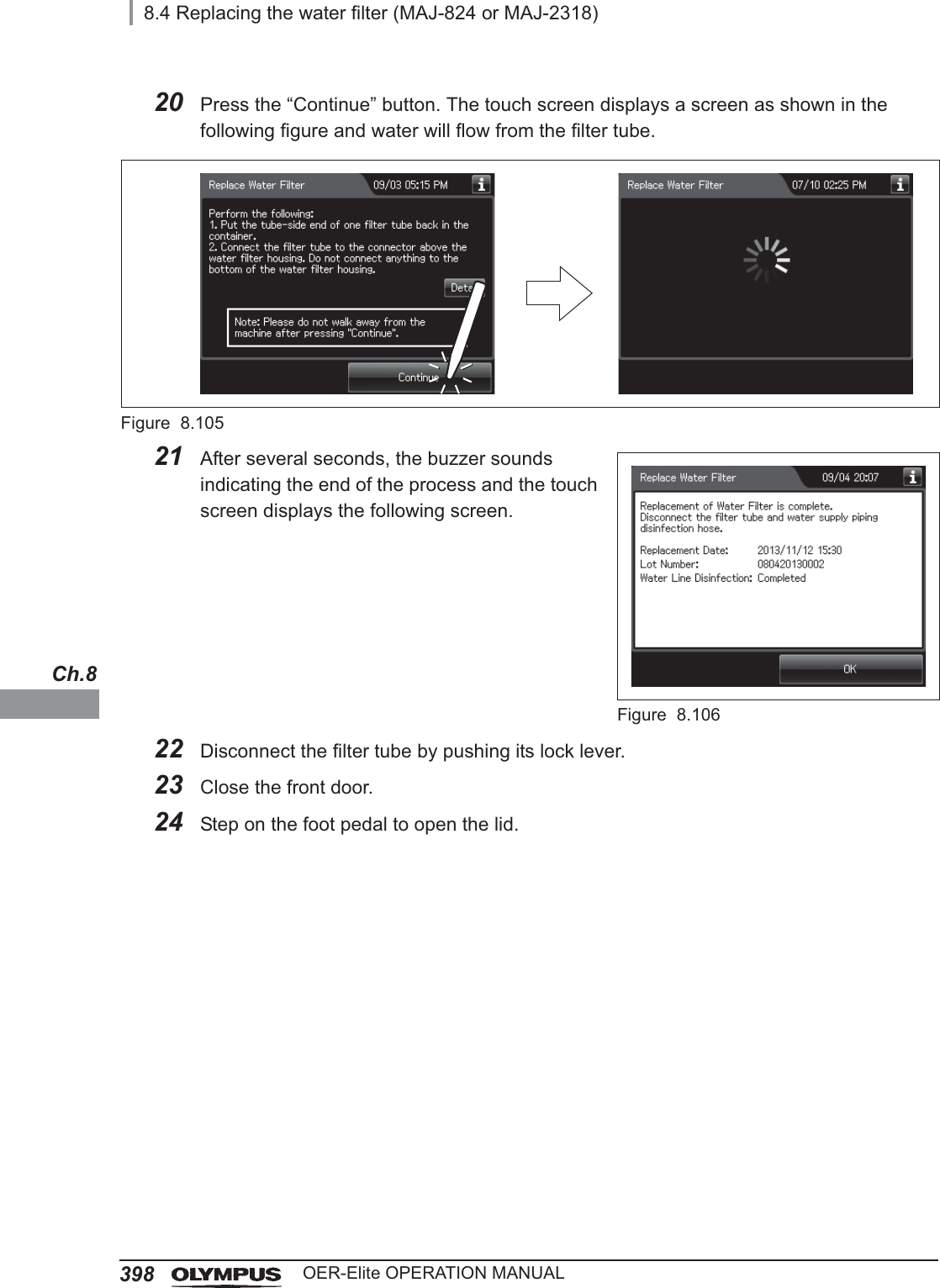
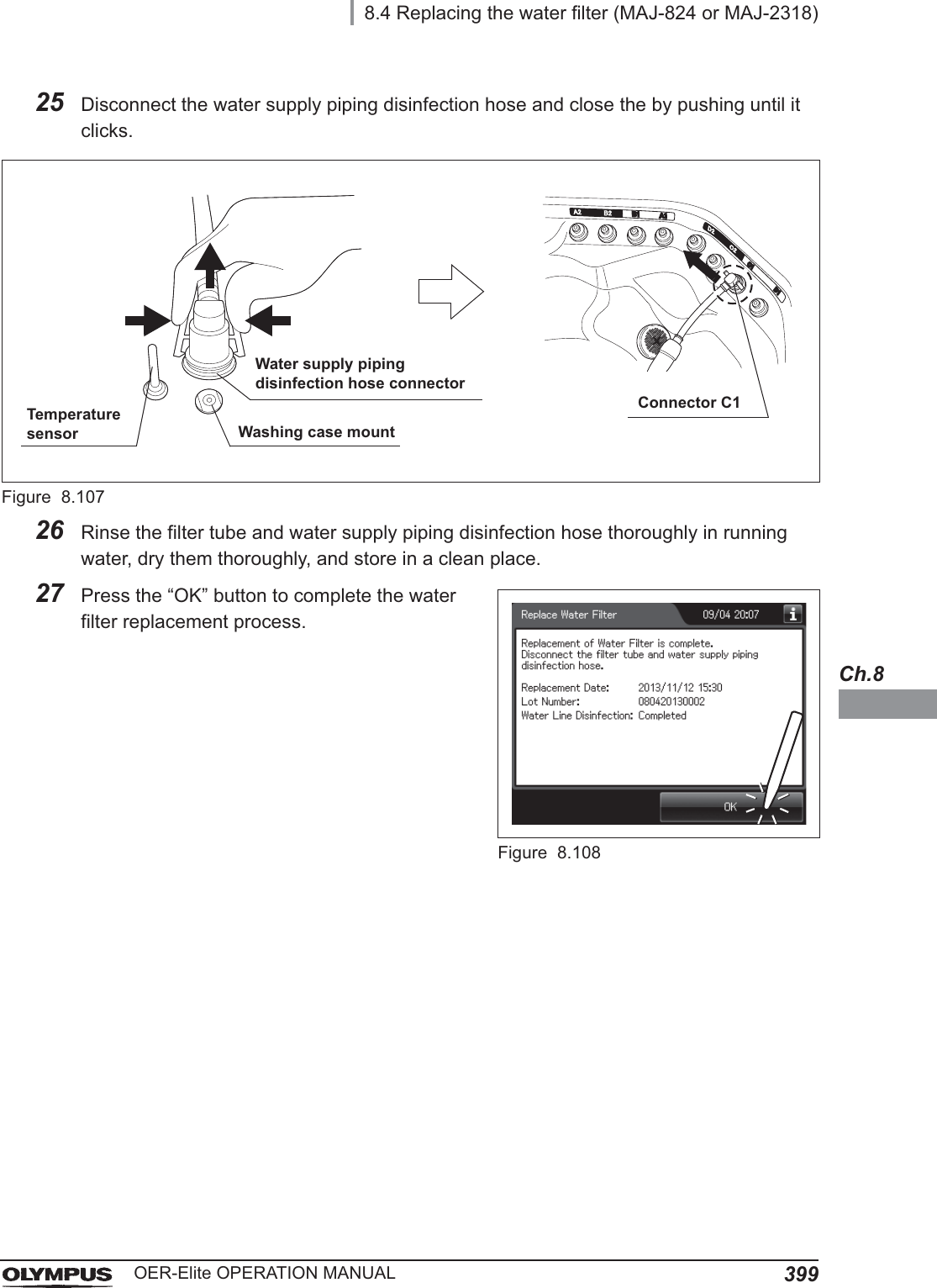
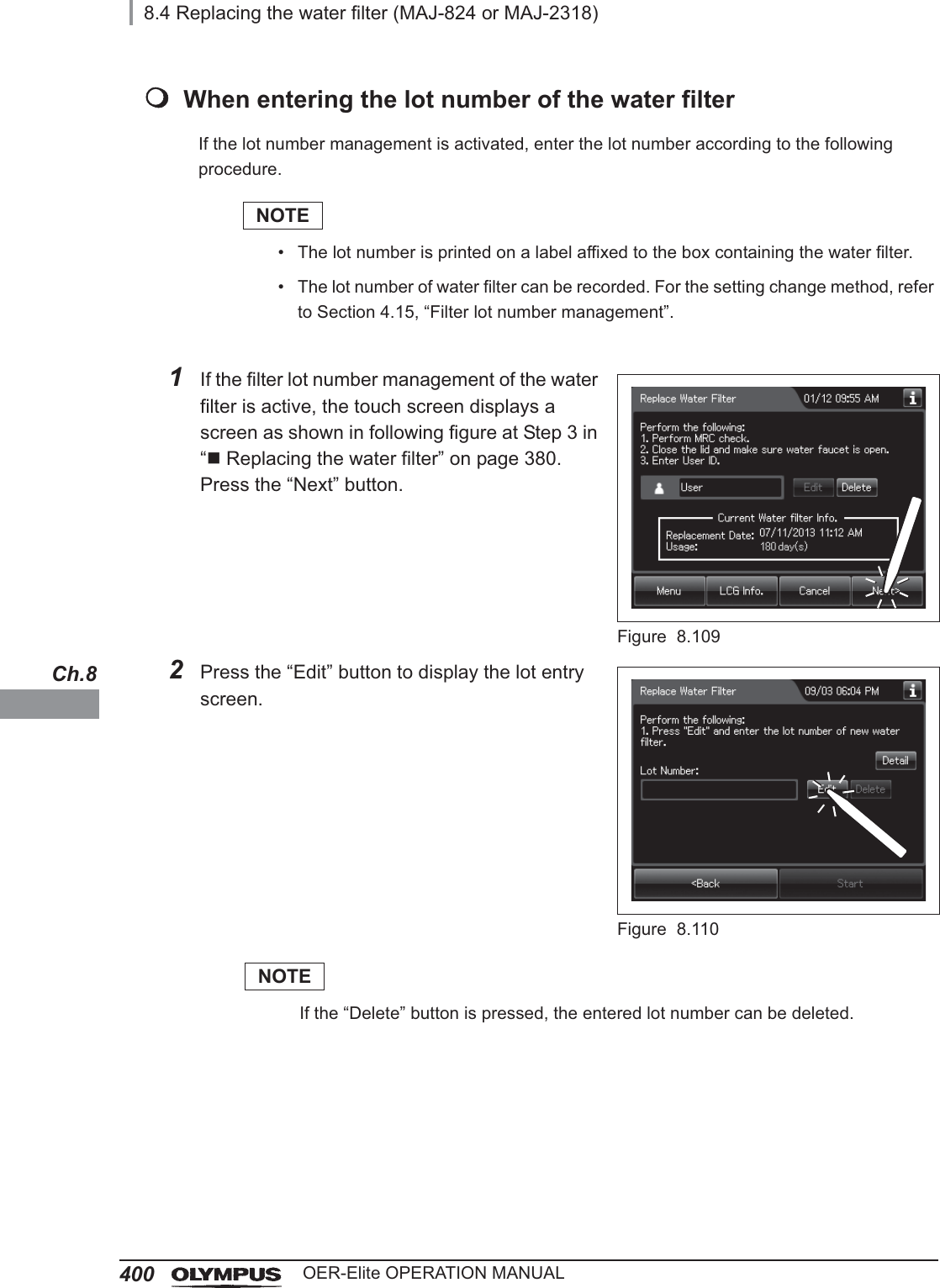
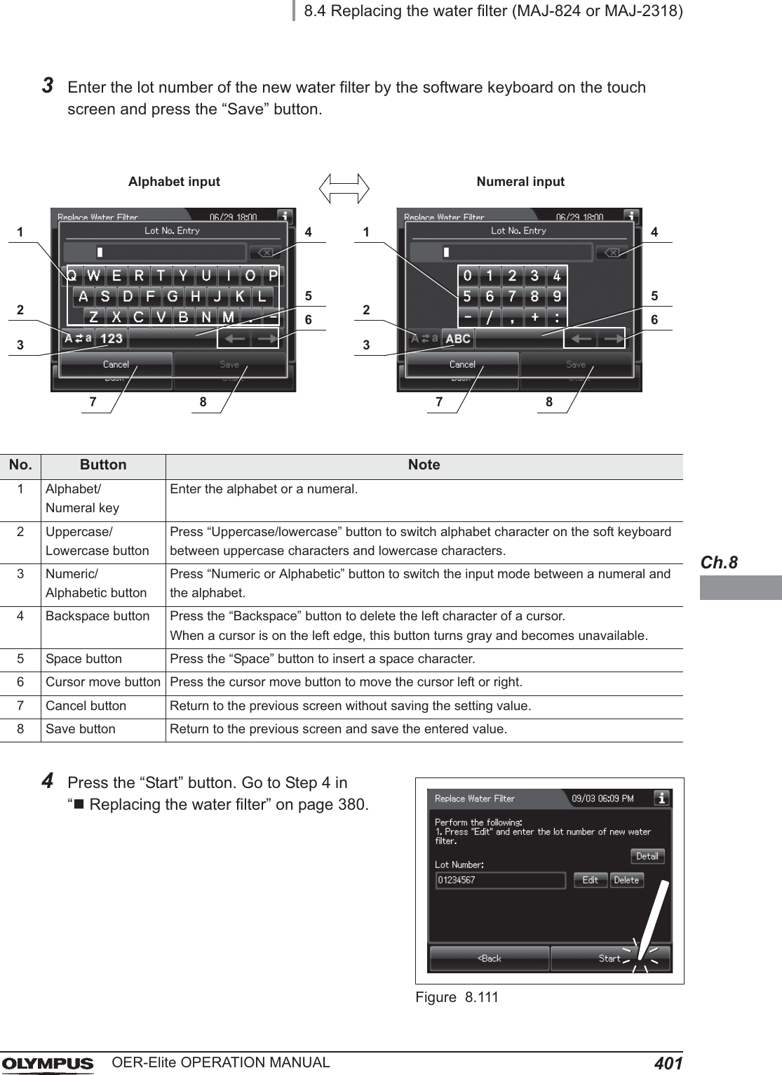
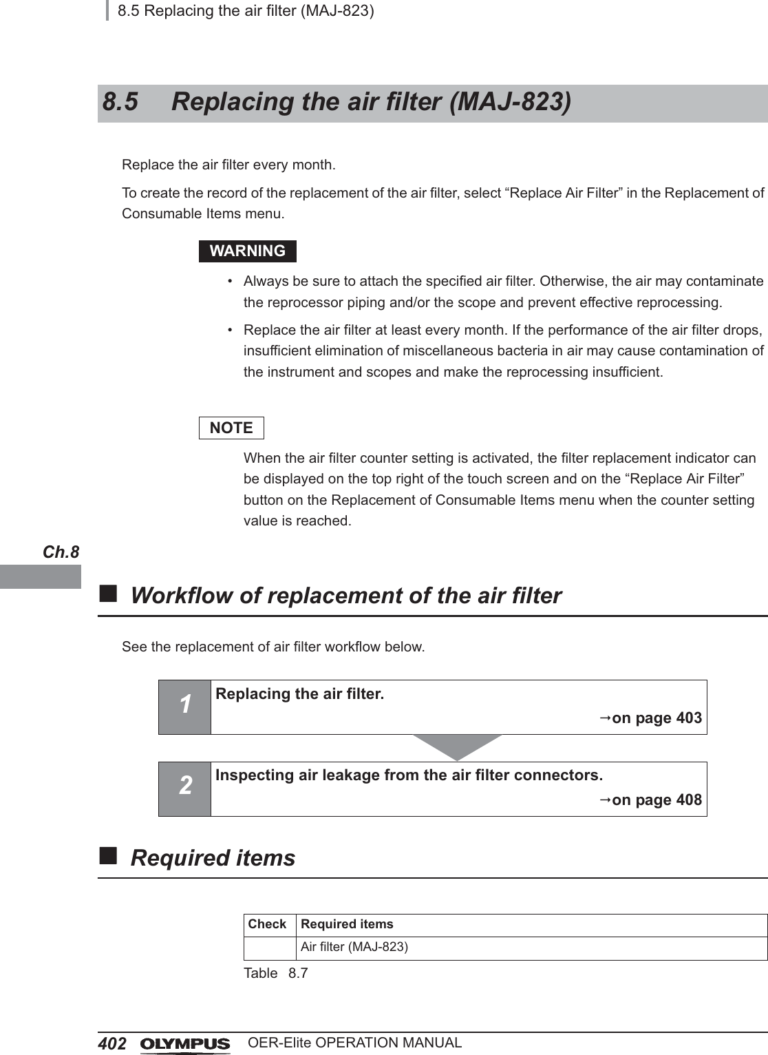
![8.4 Replacing the water filter (MAJ-824 or MAJ-2318)375OER-Elite OPERATION MANUALCh.8To prevent contamination of the rinse water, the water filter should be replaced every month when the prefilter is not used or every six months when the prefilter is used. The water filter should also be replaced whenever an error code indicating water supply insufficiency [E001] is displayed.To create the record of the replacement of the water filter, select “Replace Water Filter” in the Replacement of Consumable Items menu.WARNING• Replace the water filter in a clean environment. Do not touch the inner side of the water filter or allow dust to get in it.• Replace the water filter at least every month and pre-water filter at least every six month. If the performance of the water filter drops, insufficient elimination of miscellaneous bacteria in the tap water may cause contamination of the instrument and scopes and make the reprocessing insufficient.• After replacing the water filter, be sure to perform the water line disinfection to prevent the growth of water-borne microorganisms. Failure to perform this operation could result in contamination of the reprocessor piping and ineffective reprocessing of the endoscope.• Always be sure to attach the specified water filter. Otherwise, water-borne microorganisms and particulates in the water may contaminate the reprocessor piping and prevent effective reprocessing of the endoscope.• Before handling the disinfectant solution, read the SDS and instructions for use of the disinfectant solution carefully, get fully accustomed to the contents, and use the disinfectant solution as instructed. Be sure to fully understand what to do if the disinfectant solution comes in contact with your skin and eyes.• When handling the disinfectant solution, wear personal protective equipment to prevent any disinfectant from getting on your skin and eyes or being inhaled. Avoid direct physical contact and inhalation of vapors. If any disinfectant solution gets in your eyes, immediately rinse with a large amount of fresh water and then consult a medical specialist. Wear personal protective equipment, such as eyewear, face mask, moisture-resistant clothing, and chemical-resistant gloves that fit properly and are long enough so that your skin and eyes is not exposed. All personal protective equipment should be inspected before use and replaced periodically before it is damaged.8.4 Replacing the water filter (MAJ-824 or MAJ-2318)](https://usermanual.wiki/Olympus-Medical-Systems/RU2020.Operation-Manual-3/User-Guide-3575683-Page-109.png)