Olympus Medical Systems RU2020 Endoscope Reprocessor User Manual GT9882 0100 fm10
Olympus Medical Systems Corp. Endoscope Reprocessor GT9882 0100 fm10
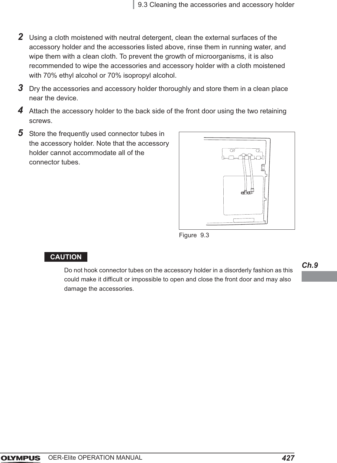
UserManual.wiki
>
Olympus Medical Systems
>
RU2020 User Manual
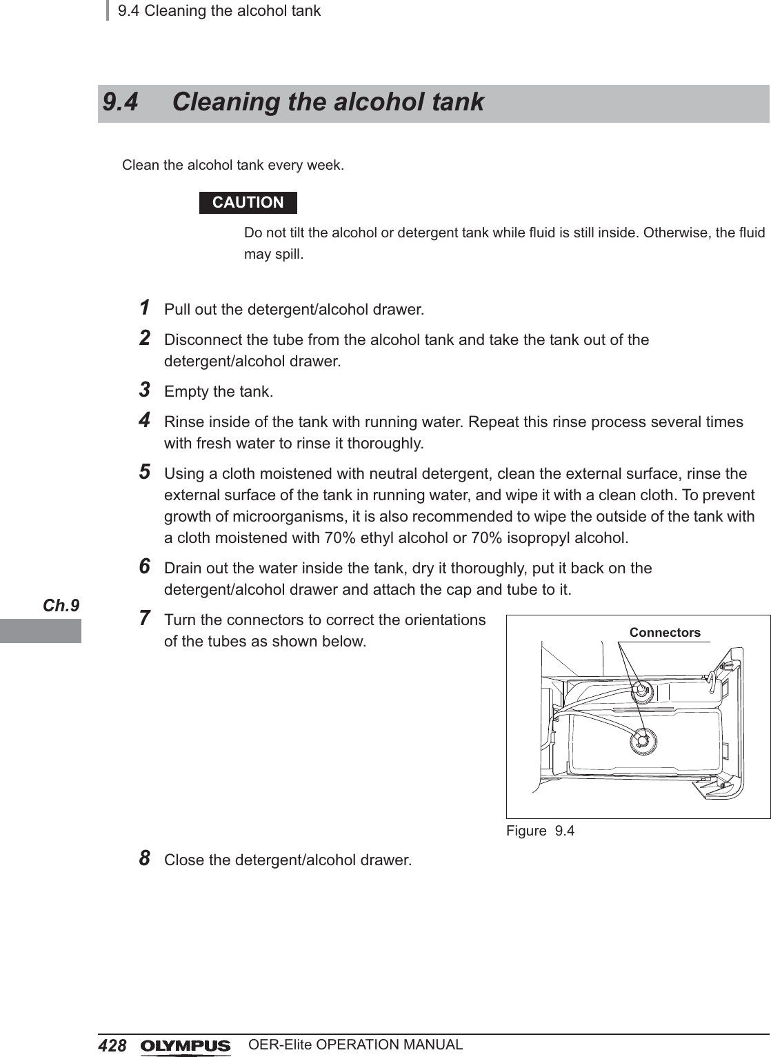
>
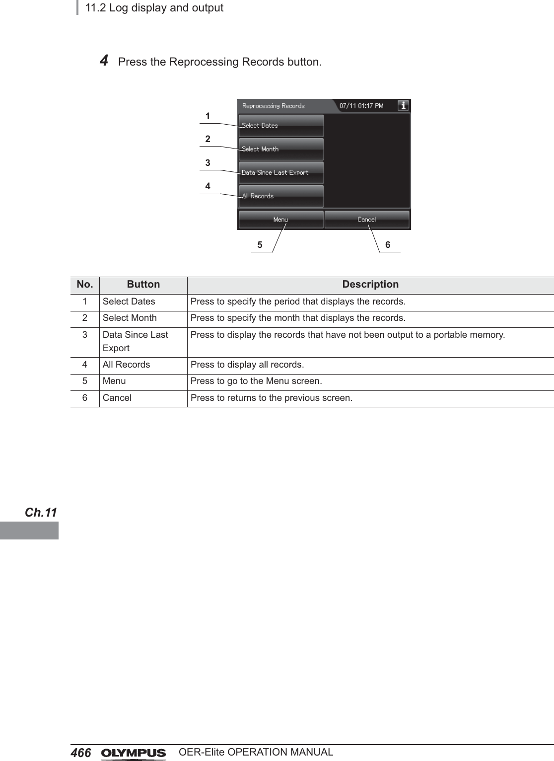
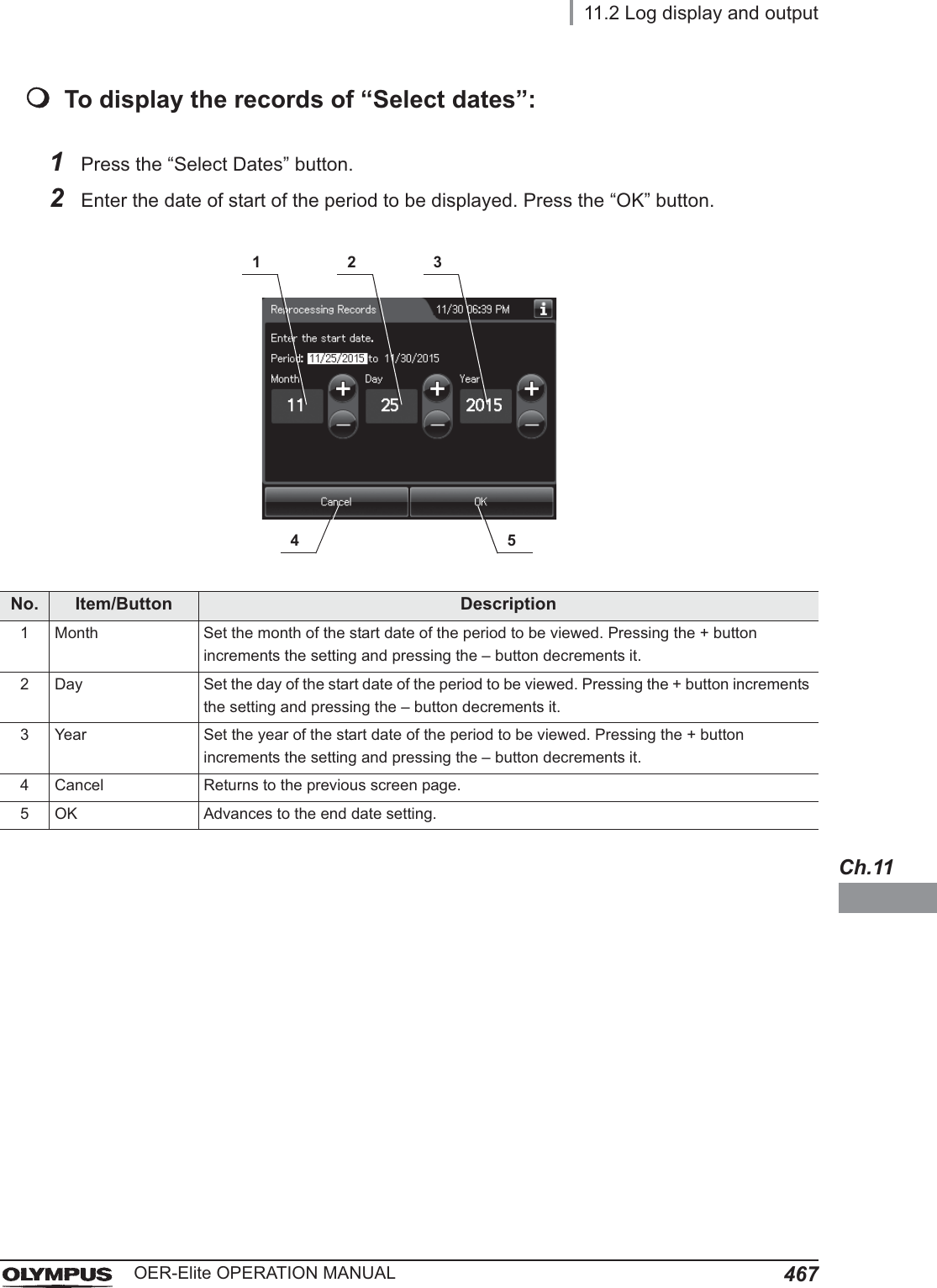
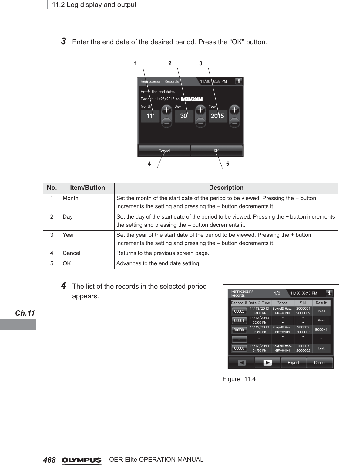
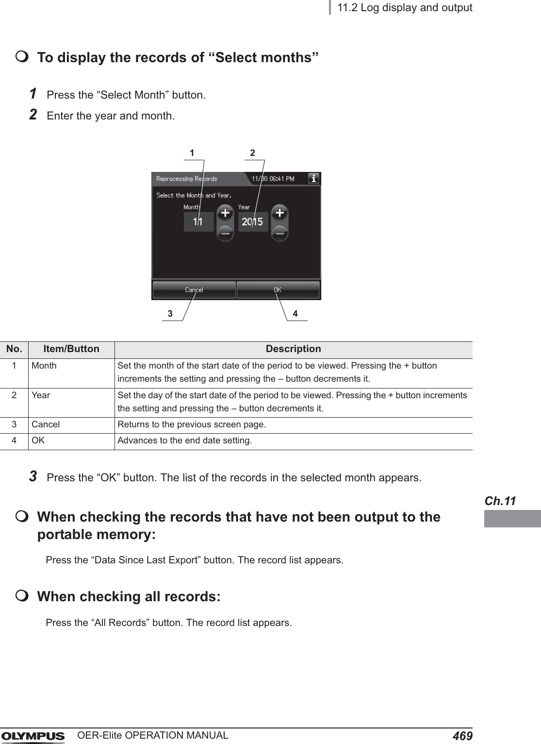
Operation Manual 4
Contents
1.
Operation Manual 1
2.
Operation Manual 2
3.
Operation Manual 3
4.
Operation Manual 4
5.
Operation Manual 5
6.
Installation Manual 1
7.
Installation Manual 2
Operation Manual 4
Navigation menu
Upload a User Manual
Namespaces
Wiki Guide
HTML
PDF
Info
Views
User Manual
Discussion / Help
Navigation
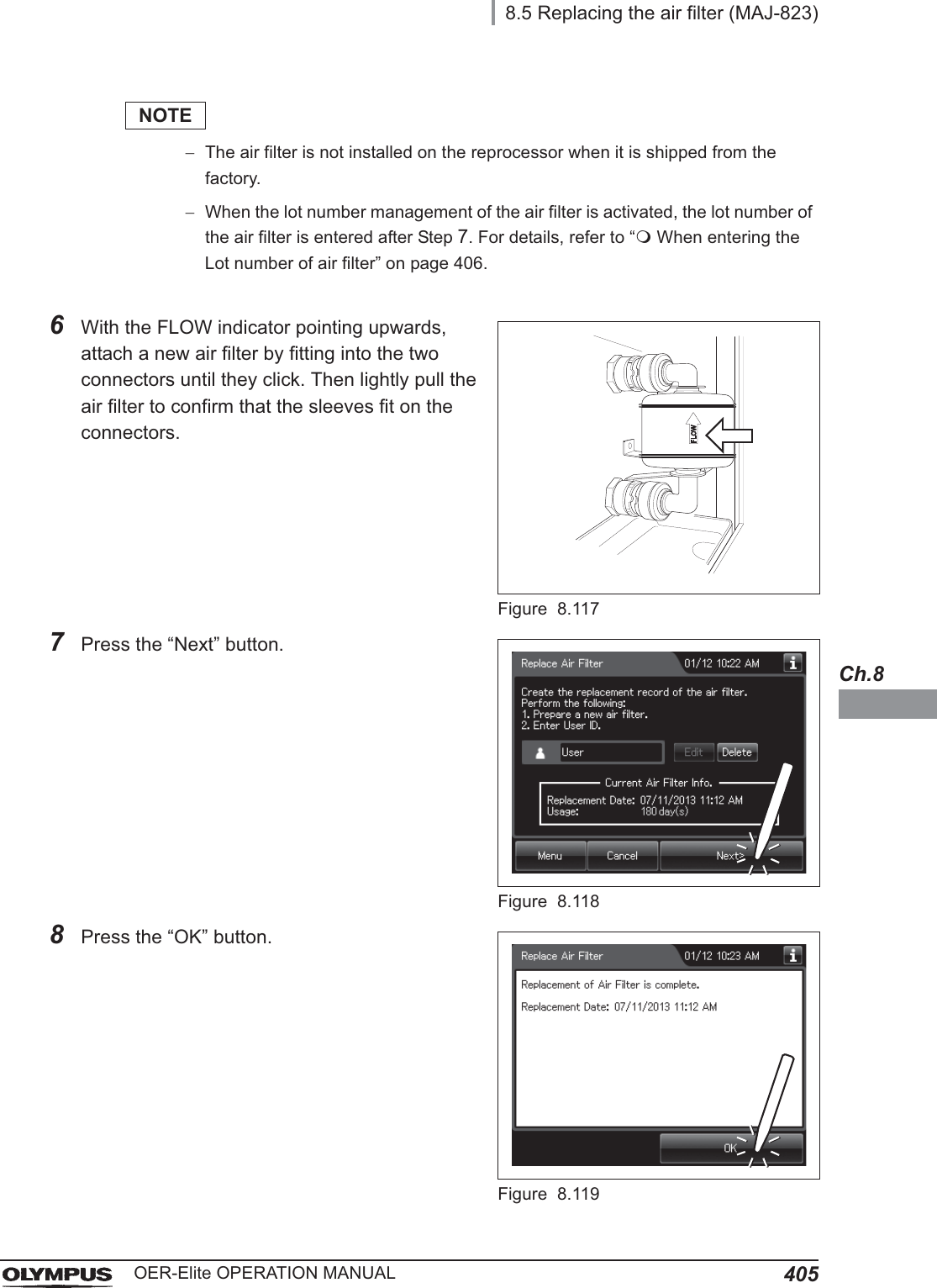
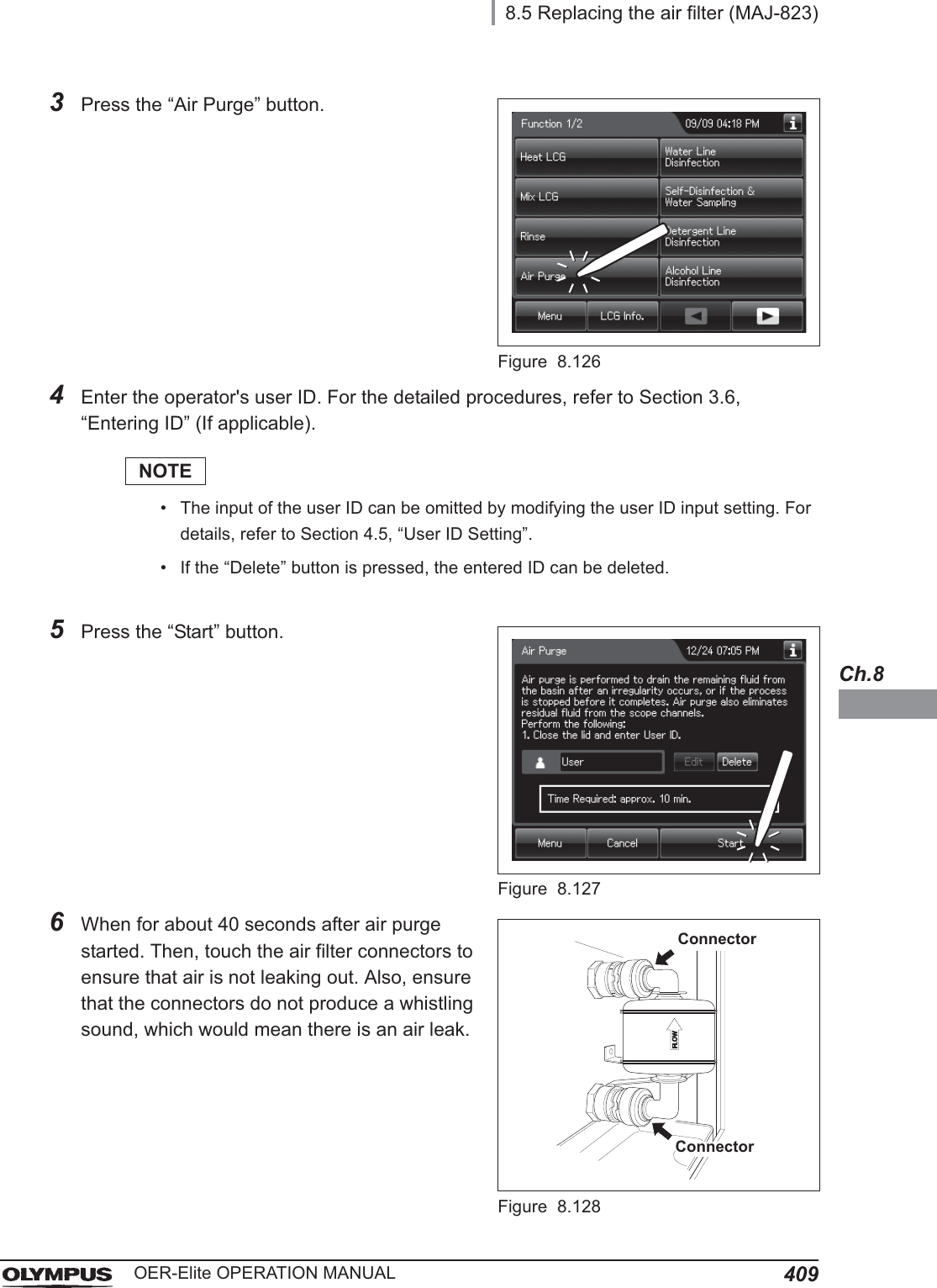
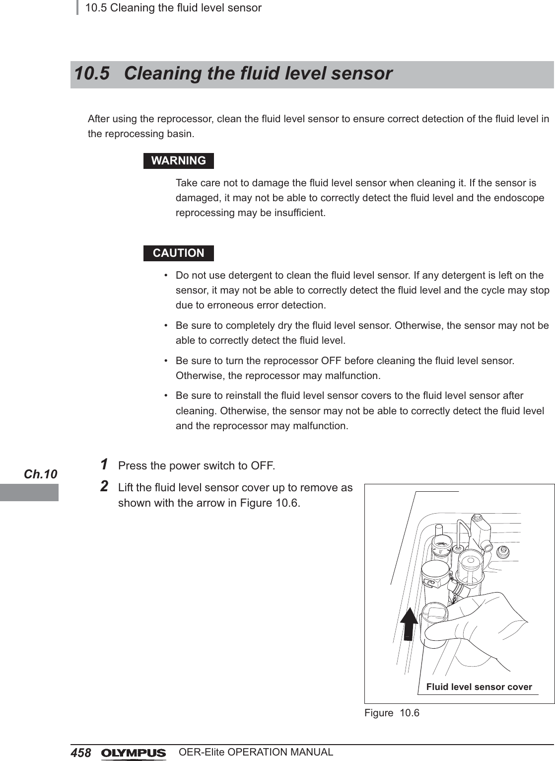
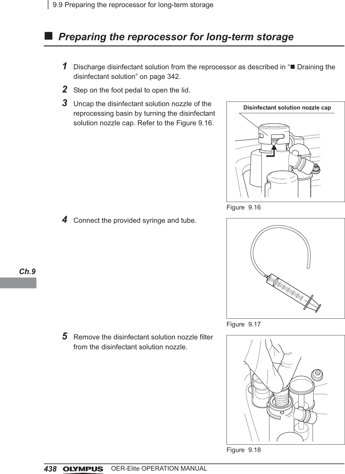
![4108.5 Replacing the air filter (MAJ-823)OER-Elite OPERATION MANUALCh.8NOTEIt takes about 40 seconds to feed air into the air filter.7Press the “Stop” button on the touch screen to end Air Purge. If an air leak is detected or the error code [E021] is displayed, reinstall the air filter as described in ͆Replacing the air filter” on page 4038The touch screen displays the error code [E000]. Press the “OK” button repeatedly until the error screen is closed.Figure 8.129](https://usermanual.wiki/Olympus-Medical-Systems/RU2020.Operation-Manual-4/User-Guide-3575687-Page-6.png)

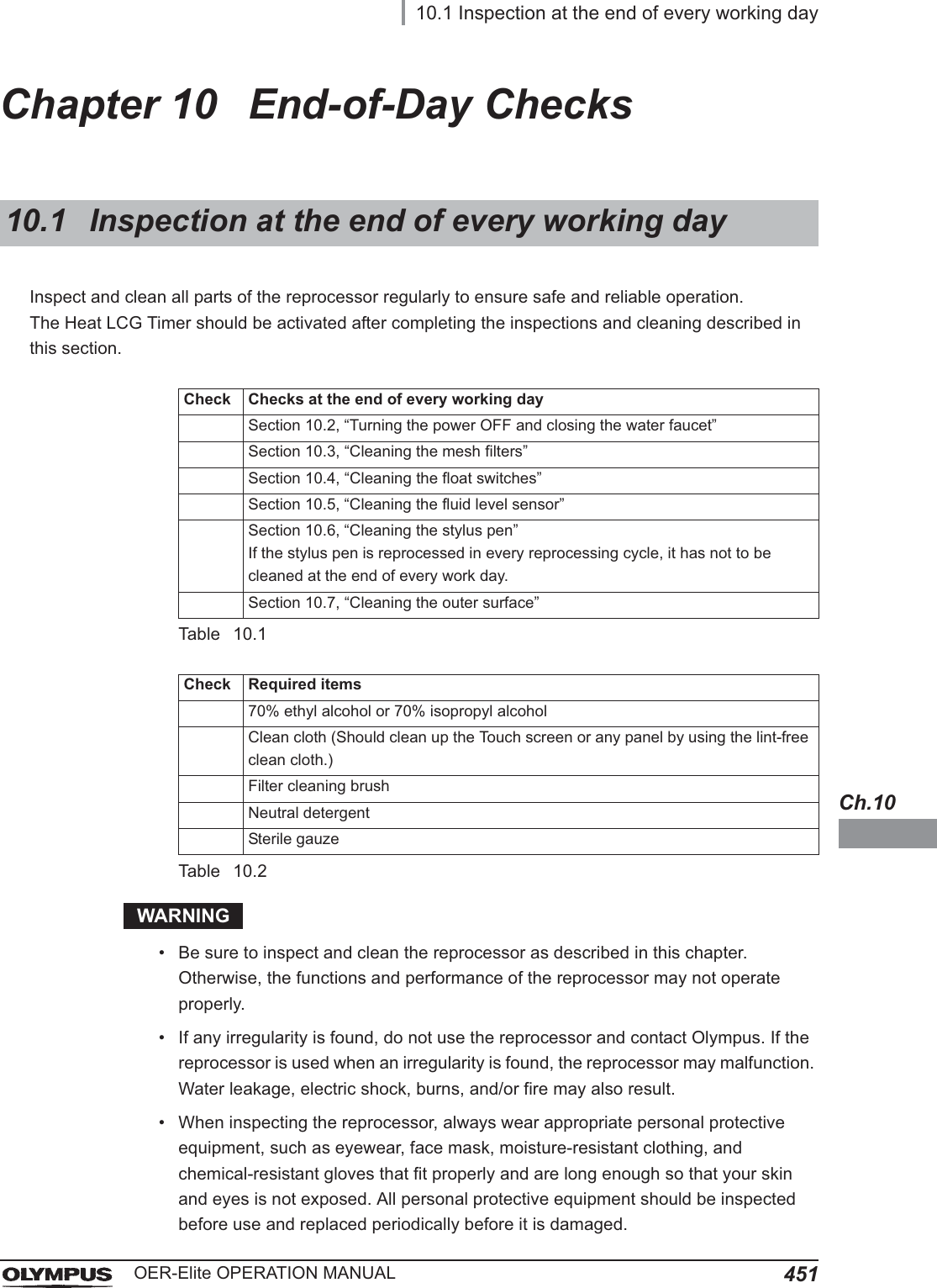
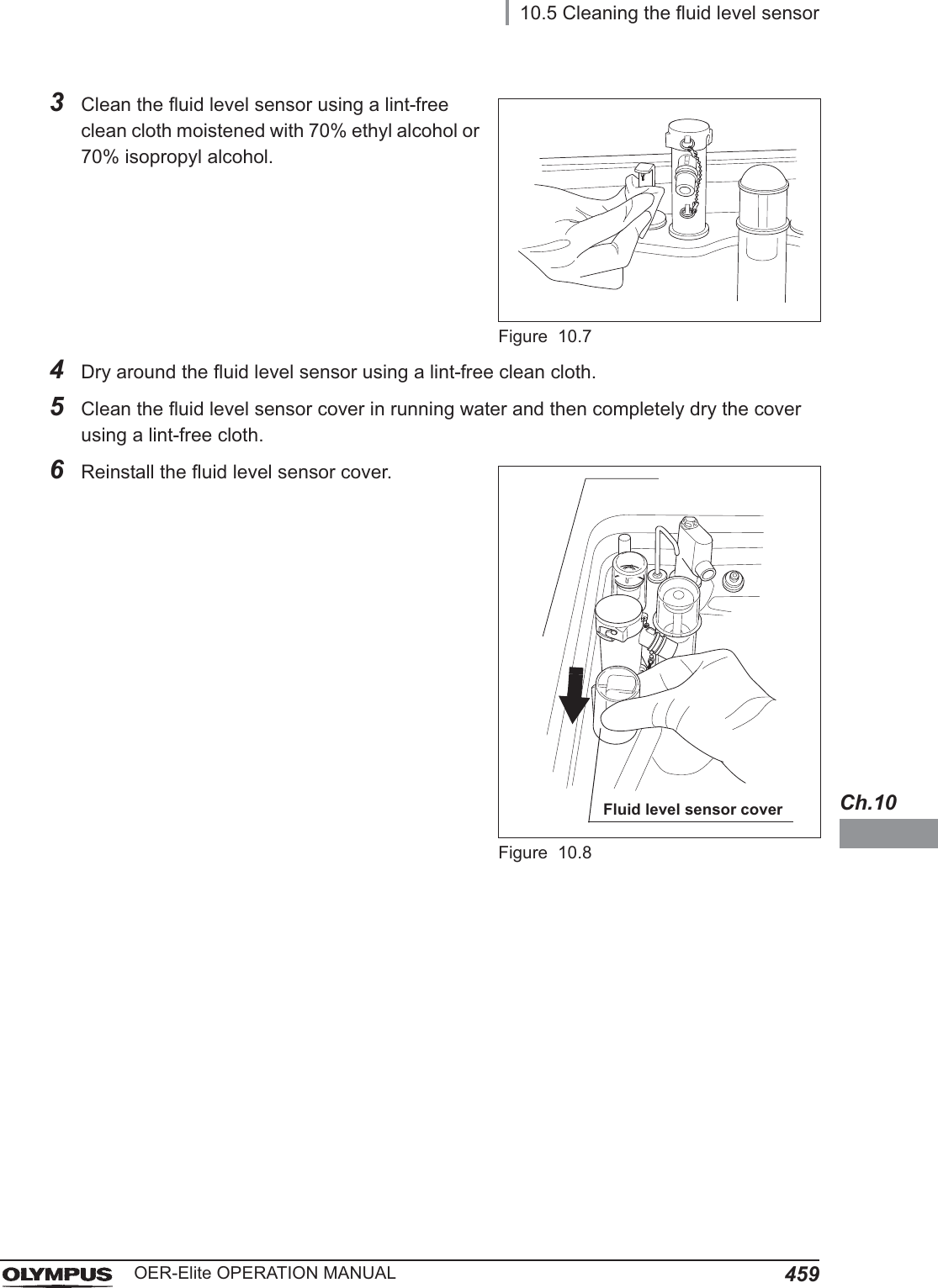
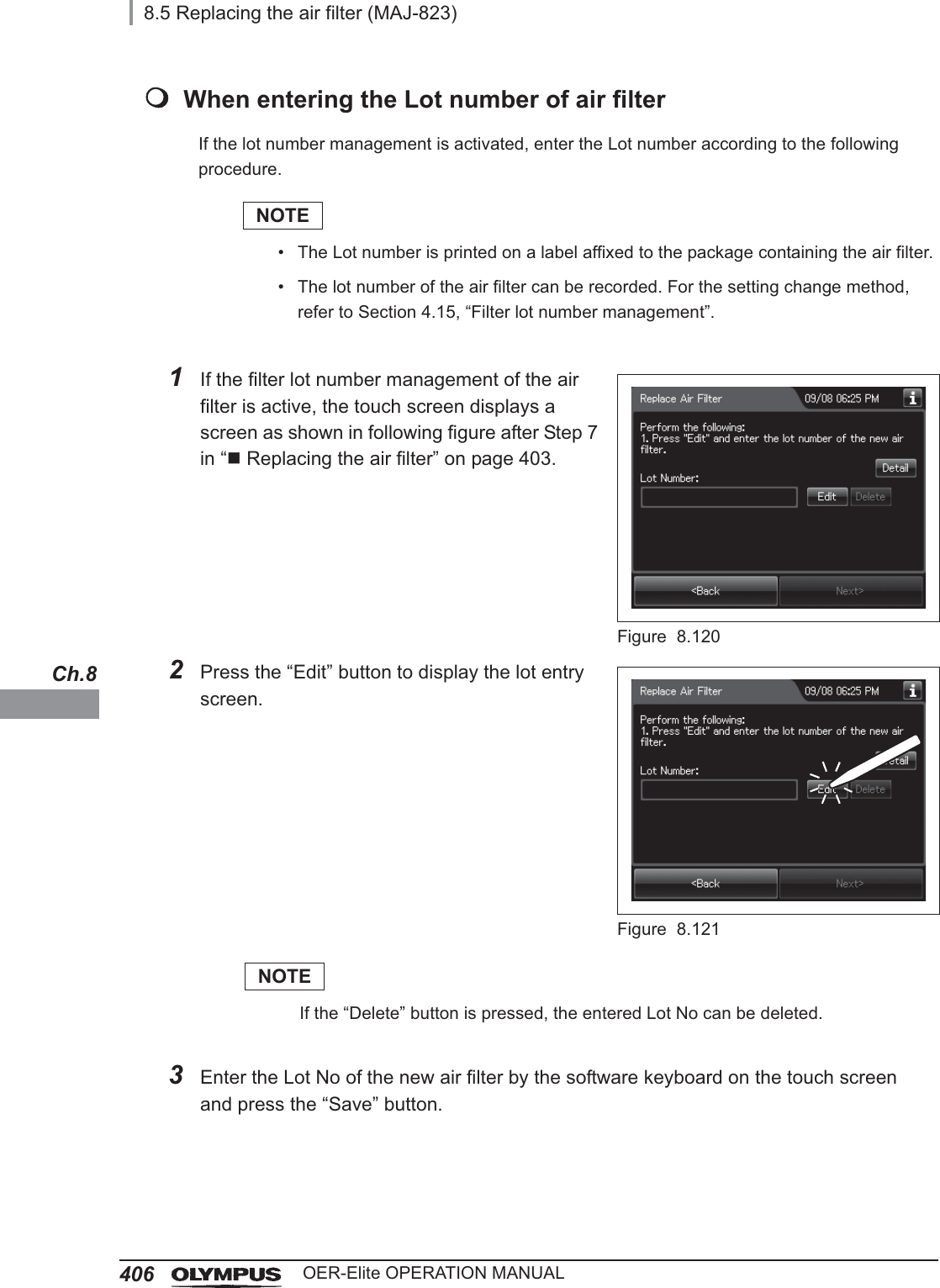
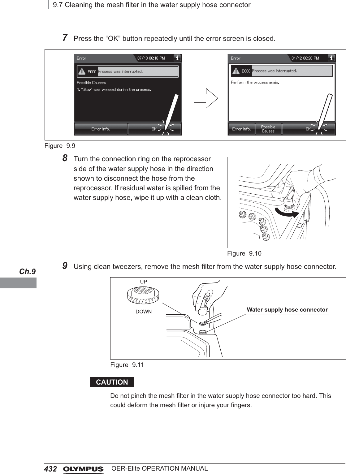
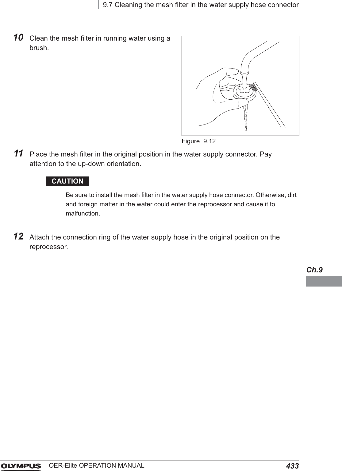
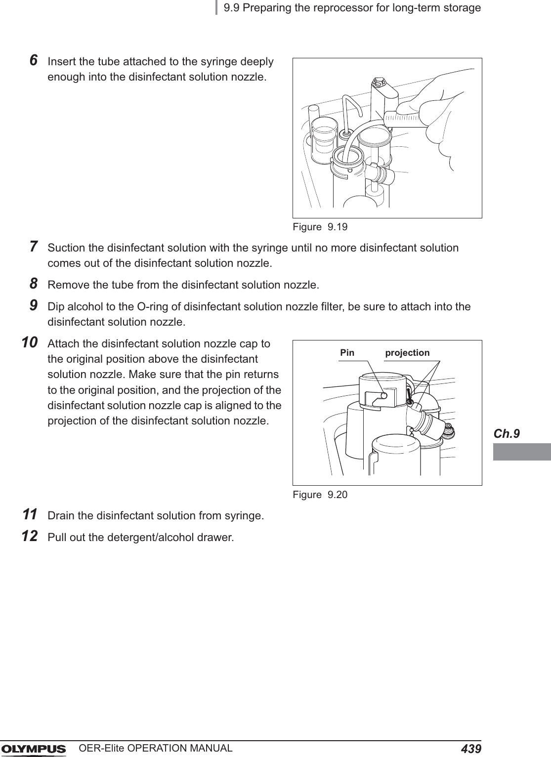
![4309.7 Cleaning the mesh filter in the water supply hose connectorOER-Elite OPERATION MANUALCh.9When the reprocessor stops with error code [E001], the water filter should be replaced first. However, if the reprocessor stops again with error code [E001], clean the mesh filter as described below.Required itemsTable 9.5Cleaning the mesh filter in the water supply hose connectorNOTETo relieve the incoming water, perform Rinse process and stop that.9.7 Cleaning the mesh filter in the water supply hose connectorCheck Required itemsUser ID cardClean tweezersBrush1Close the water faucet.2Press the “Functions” button on the Menu screen.Figure 9.5](https://usermanual.wiki/Olympus-Medical-Systems/RU2020.Operation-Manual-4/User-Guide-3575687-Page-26.png)
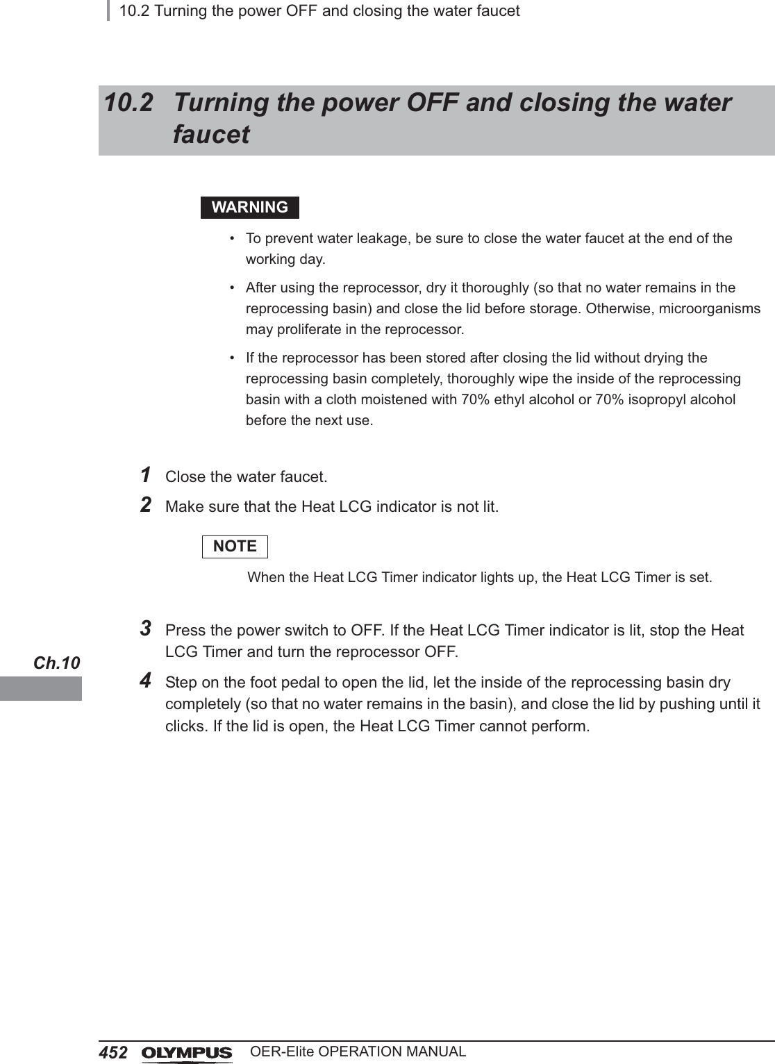
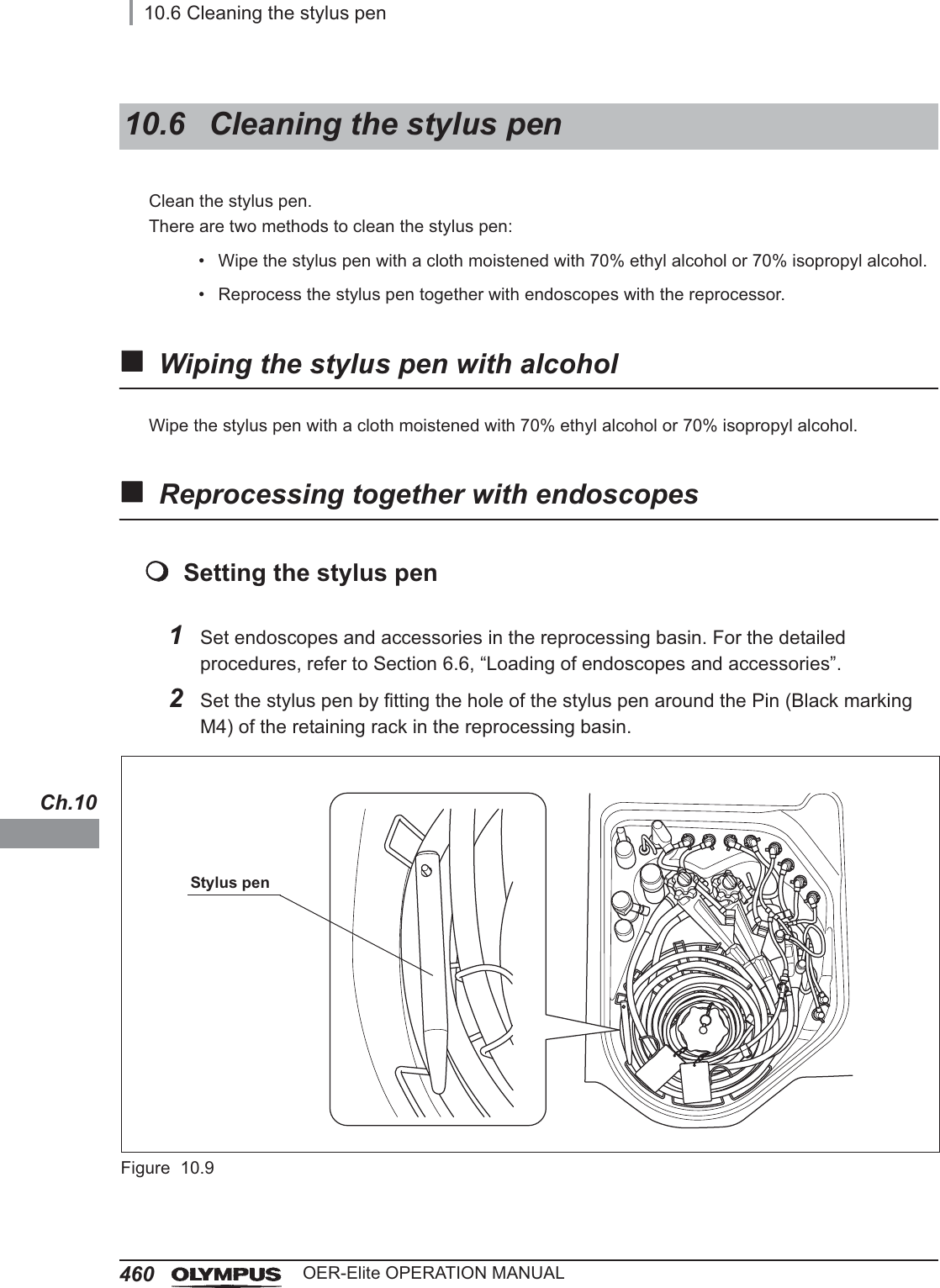
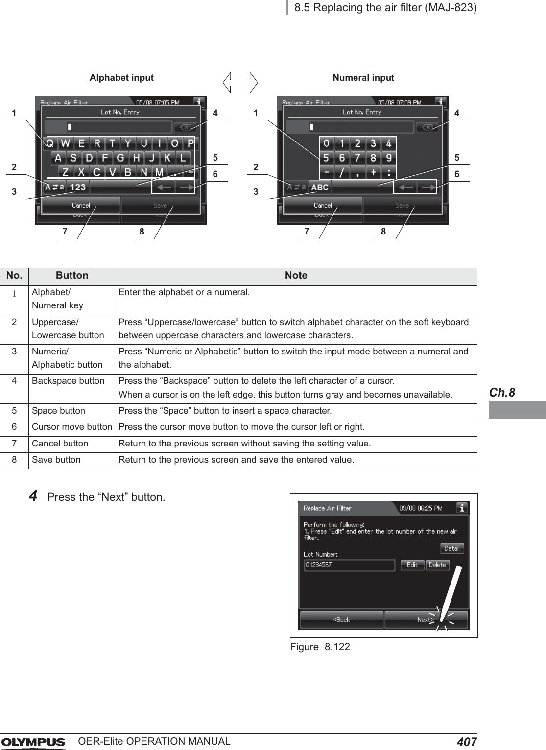
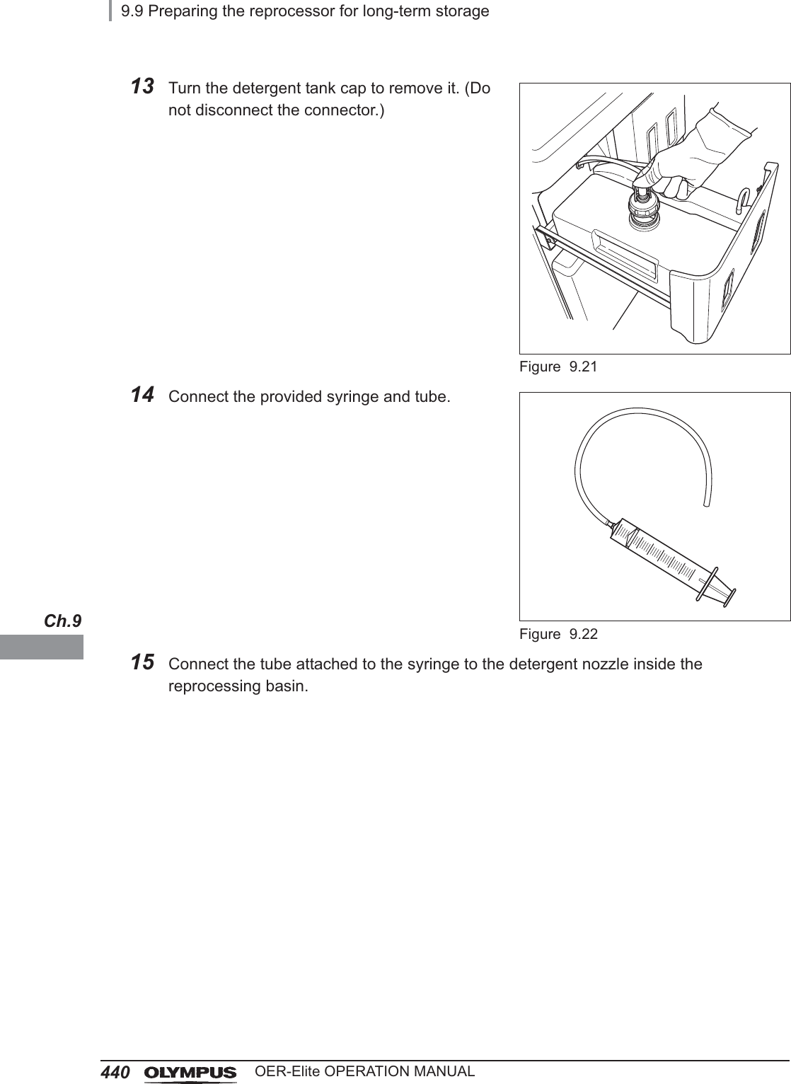
![9.7 Cleaning the mesh filter in the water supply hose connector431OER-Elite OPERATION MANUALCh.93Press the “Rinse” button.Figure 9.64Enter the operator's user ID. For the detailed procedures, refer to Section 3.6, “Entering ID” (If applicable).NOTE• The input of the user ID can be omitted by modifying the user ID input setting. For details, refer to Section 4.5, “User ID Setting”.• If the “Delete” button is pressed, the entered ID can be deleted.5Press the “Start” button to relieve the incoming water pressure.Figure 9.76After the pressure has been relieved (approximately 10 seconds), press the “STOP” button on the control panel to stop the rinse. The touch screen displays the error code [E000].Figure 9.8](https://usermanual.wiki/Olympus-Medical-Systems/RU2020.Operation-Manual-4/User-Guide-3575687-Page-27.png)
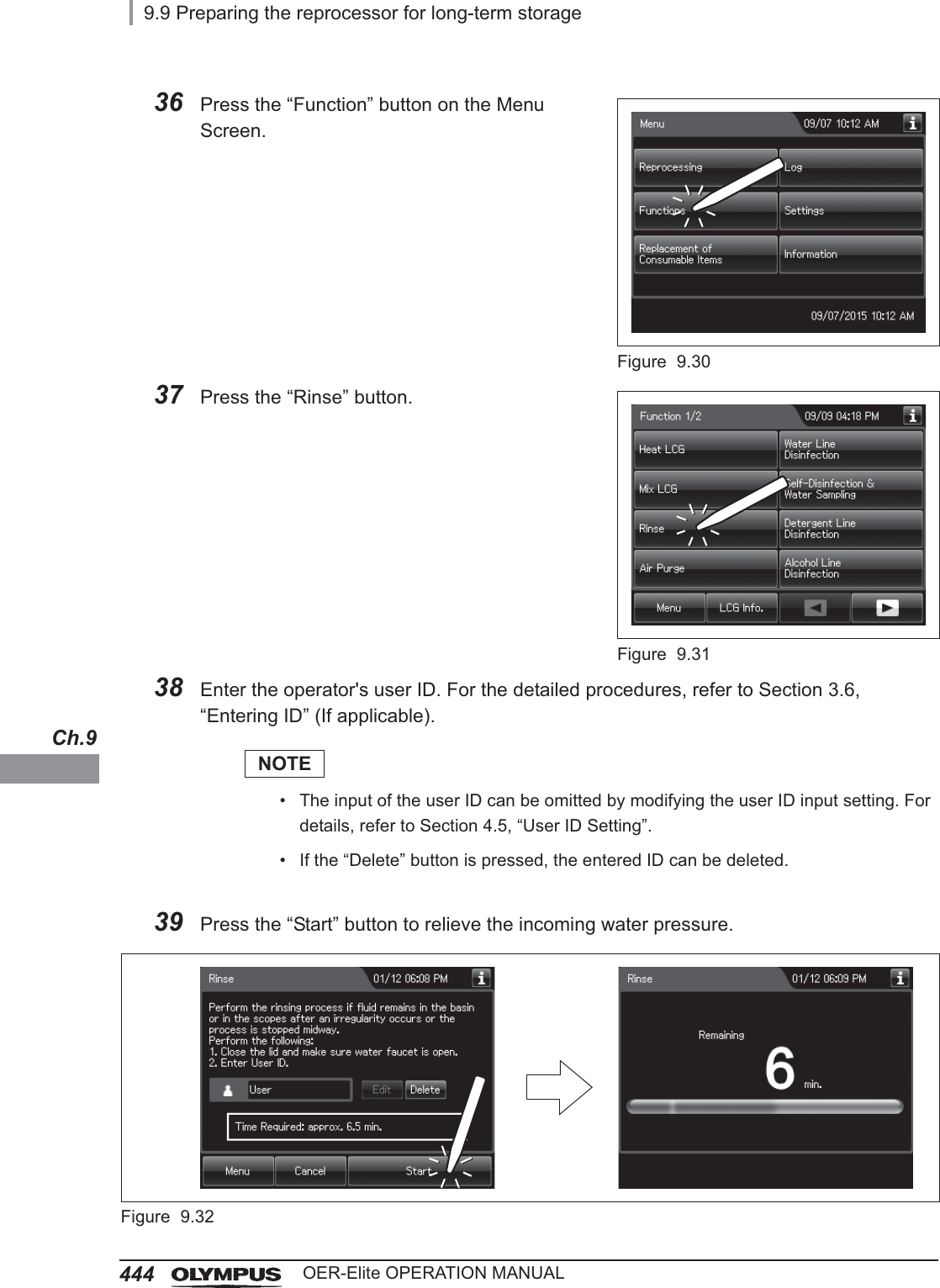
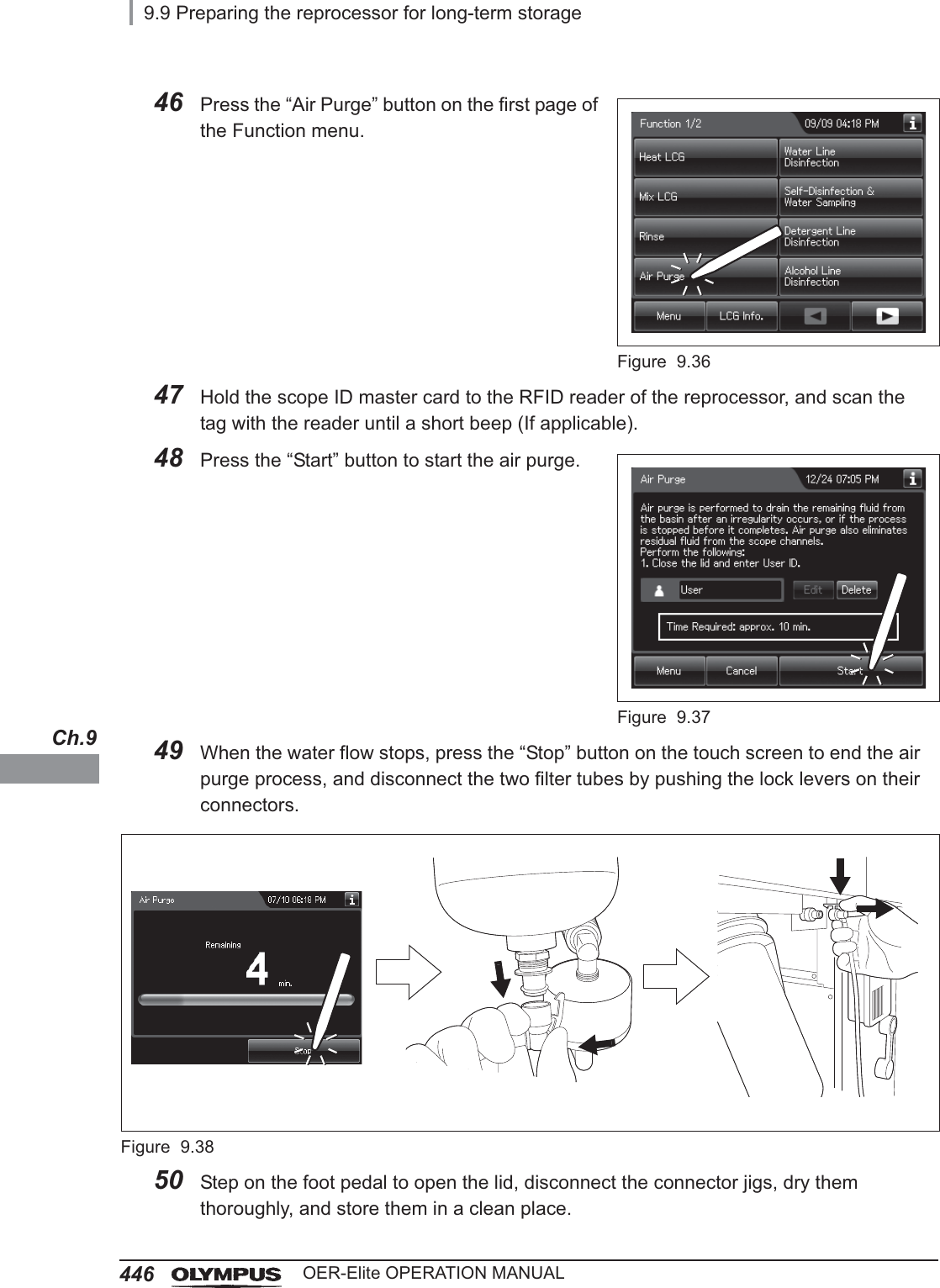
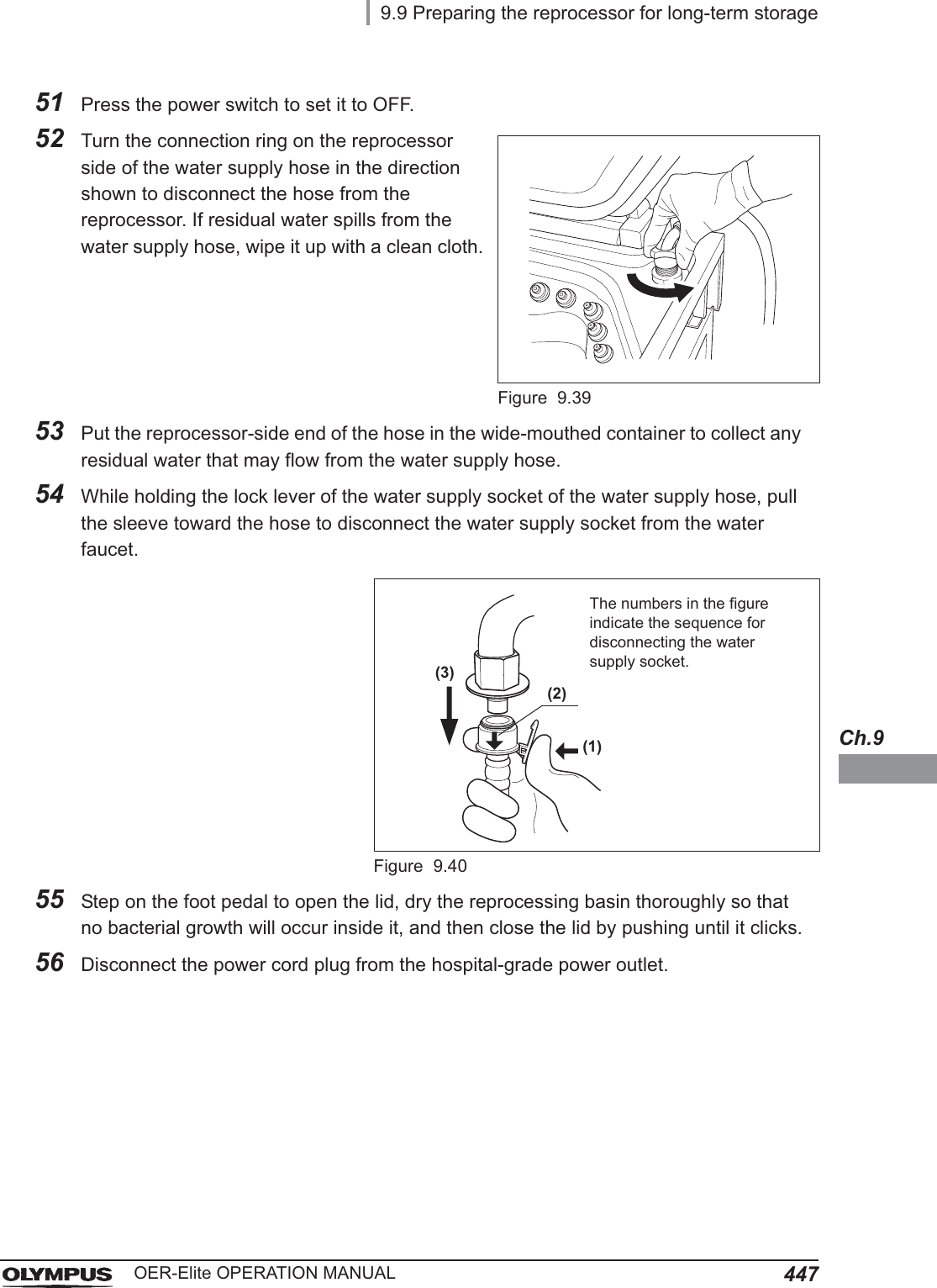
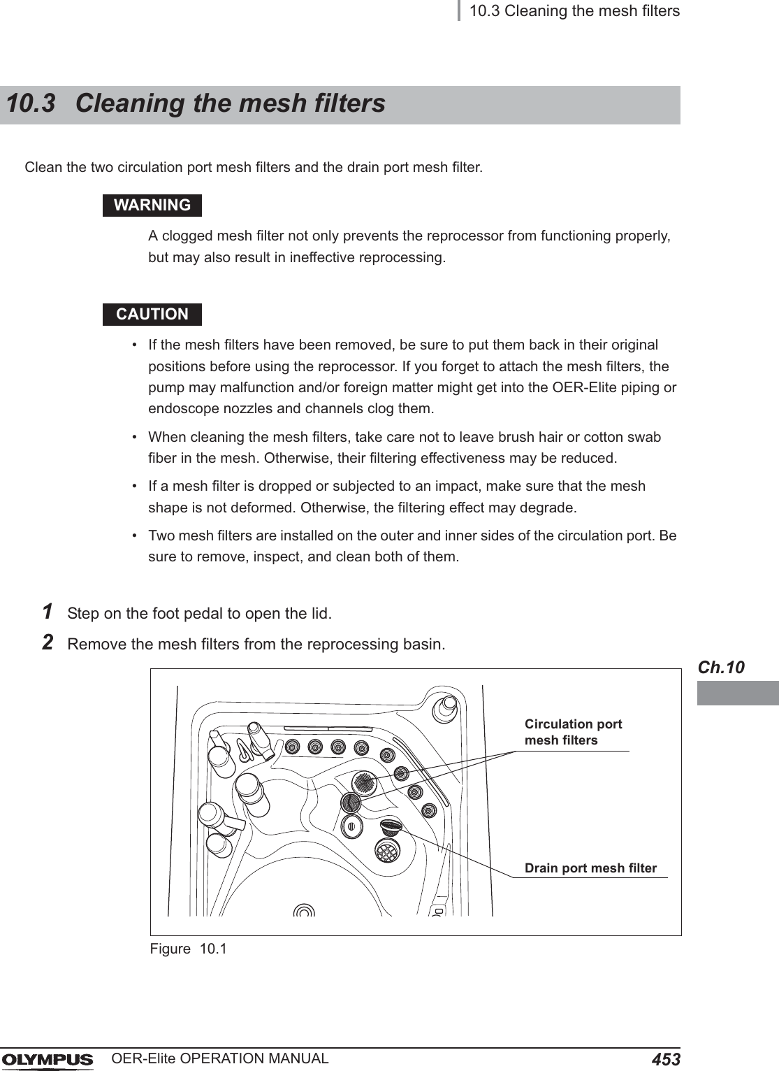
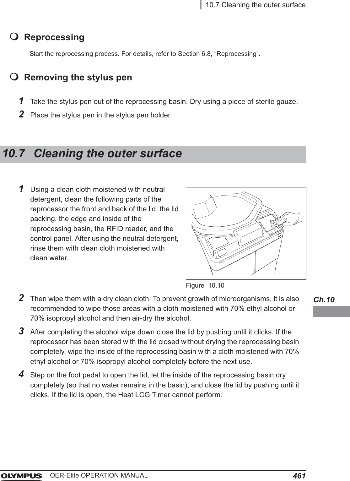
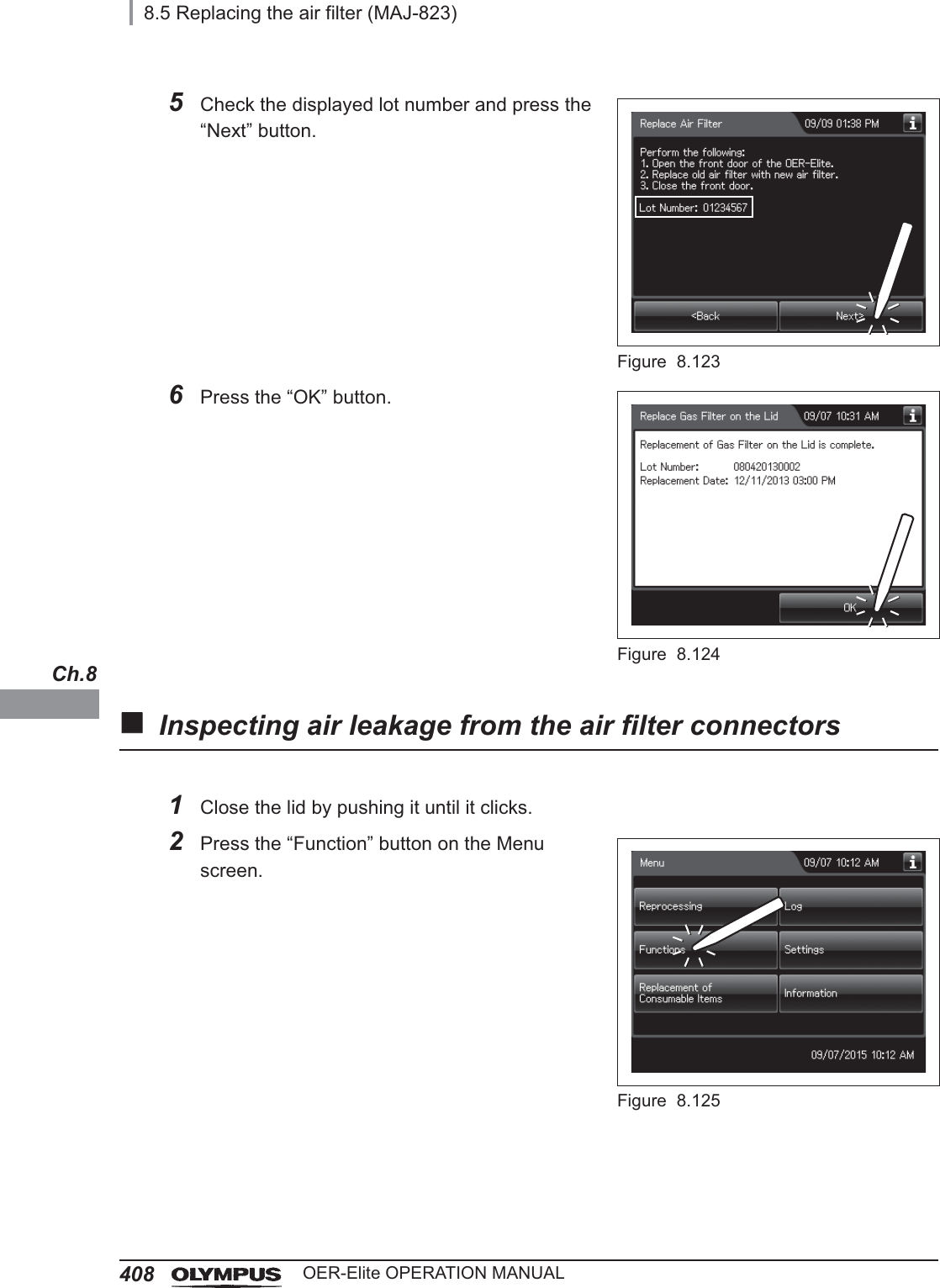
![9.9 Preparing the reprocessor for long-term storage445OER-Elite OPERATION MANUALCh.940 Press the “STOP” button on the control panel to stop the rinse. The touch screen displays the error code [E000].Figure 9.3341 Press the “OK” button repeatedly until the error screen is closed.Figure 9.3442 Open the front door of the reprocessor.43 Place a container with a capacity of 2 L or more in front of the reprocessor.44 Put the tube-side ends of the two filter tubes in the container placed above.45 Insert the connector ends of the two filter tubes into the connector below the water filter housing and the connector above the water filter housing until they click. Water will start to flow from the tube connected to the connector below the water filter housing.Figure 9.35Connector below water filter housingConnector above water filter housing](https://usermanual.wiki/Olympus-Medical-Systems/RU2020.Operation-Manual-4/User-Guide-3575687-Page-41.png)