PERVASIVE DISPLAYS S0000AZ0R3 Eco-Sign ZigBee Gateway User Manual
PERVASIVE DISPLAYS INC. Eco-Sign ZigBee Gateway Users Manual
UserManual.wiki
>
PERVASIVE DISPLAYS
>
S0000AZ0R3 User Manual
Users Manual
Navigation menu
Upload a User Manual
Namespaces
Wiki Guide
HTML
PDF
Info
Views
User Manual
Discussion / Help
Navigation
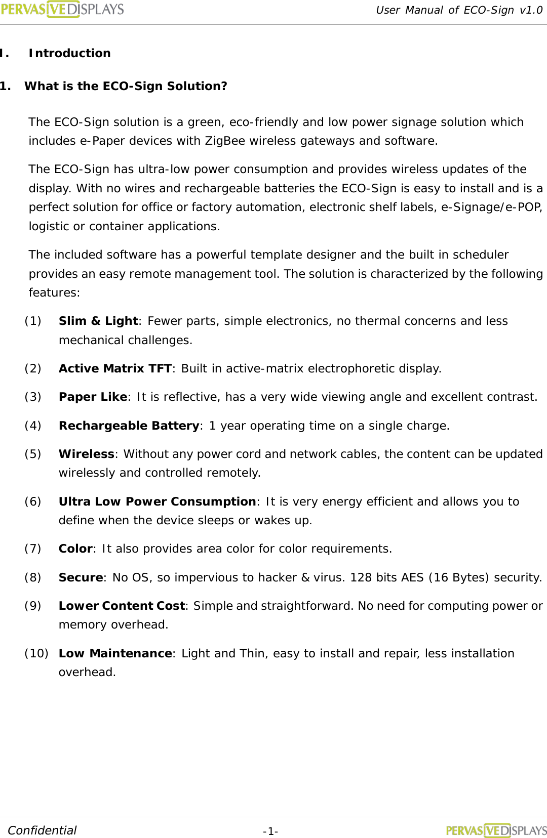
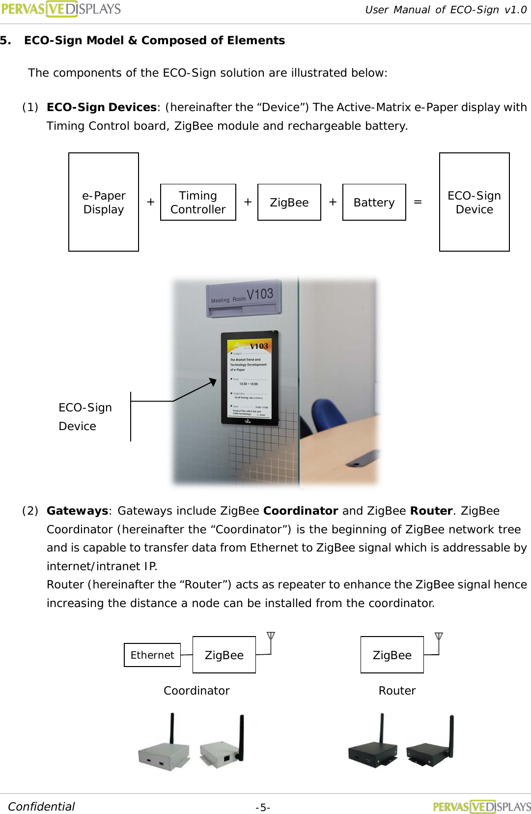
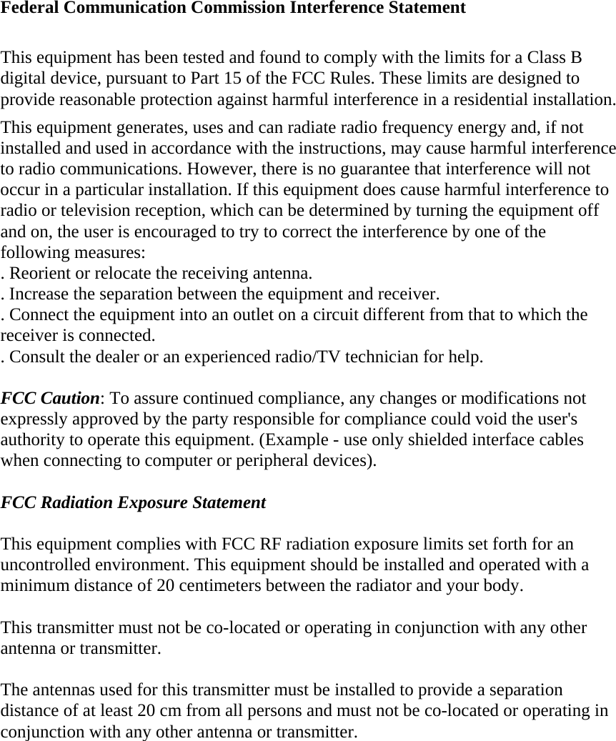
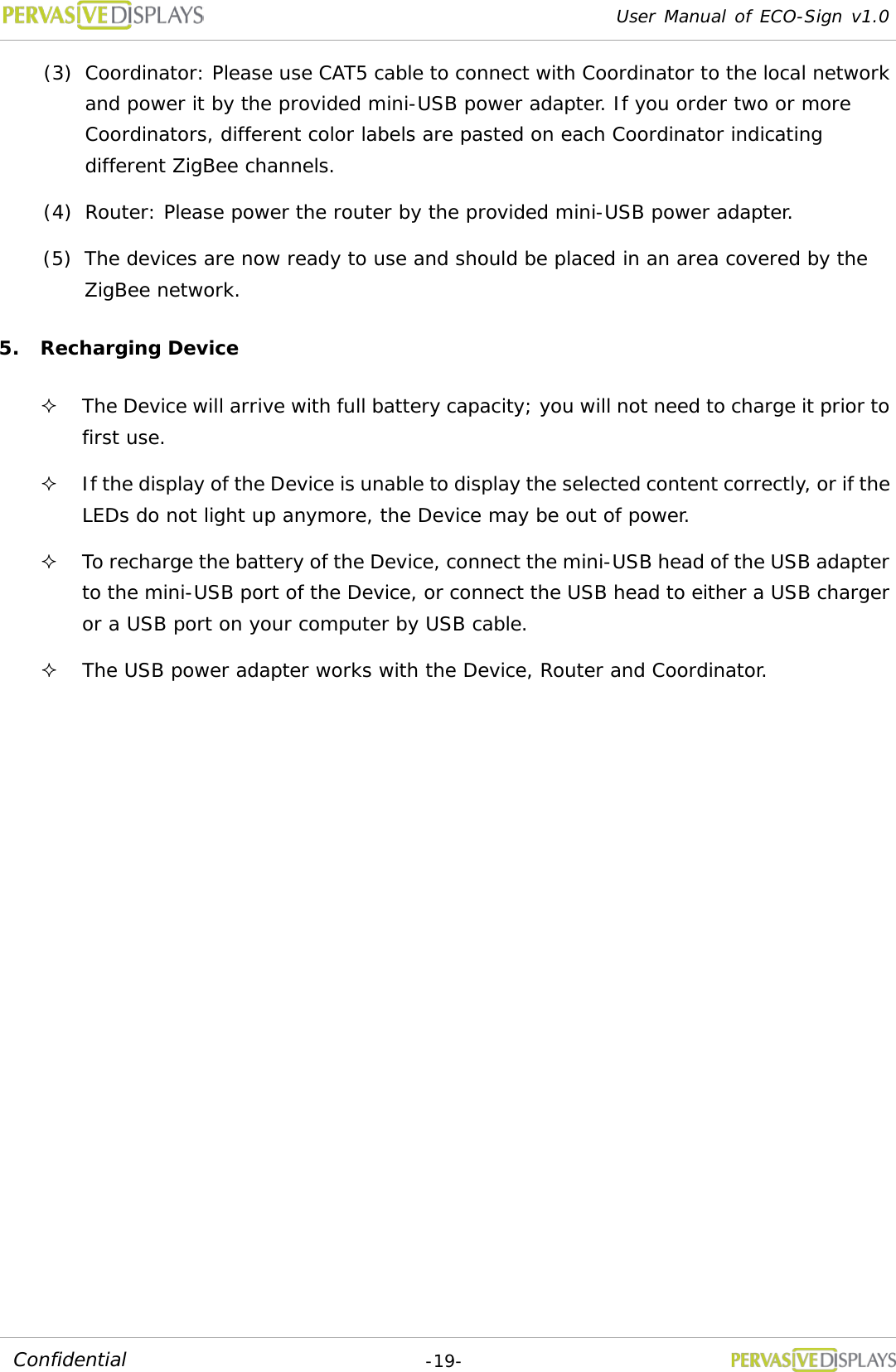
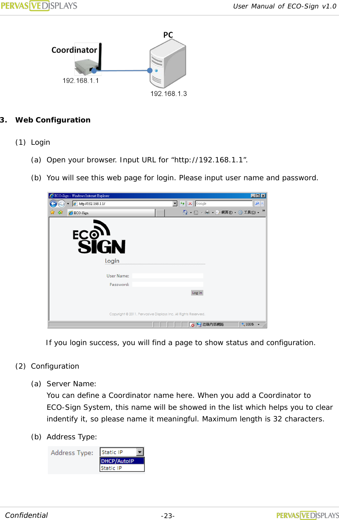
![User Manual of ECO-Sign v1.0 -9- Confidential (4) Activate the ECO-Sign: (a) Flip the power switch on the ECO-Sign and copy the discovered MAC address on the EPD Device tab. (b) Select the size and target template. Click [Add/Update] to link the Device and wait for Device to update.](https://usermanual.wiki/PERVASIVE-DISPLAYS/S0000AZ0R3/User-Guide-1586384-Page-12.png)
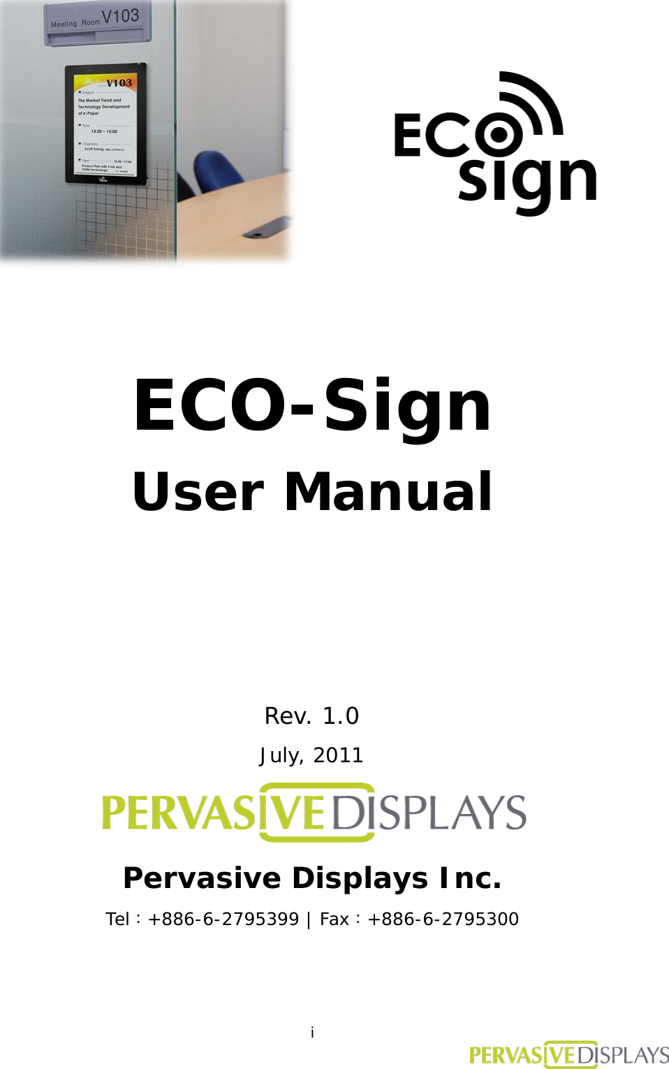
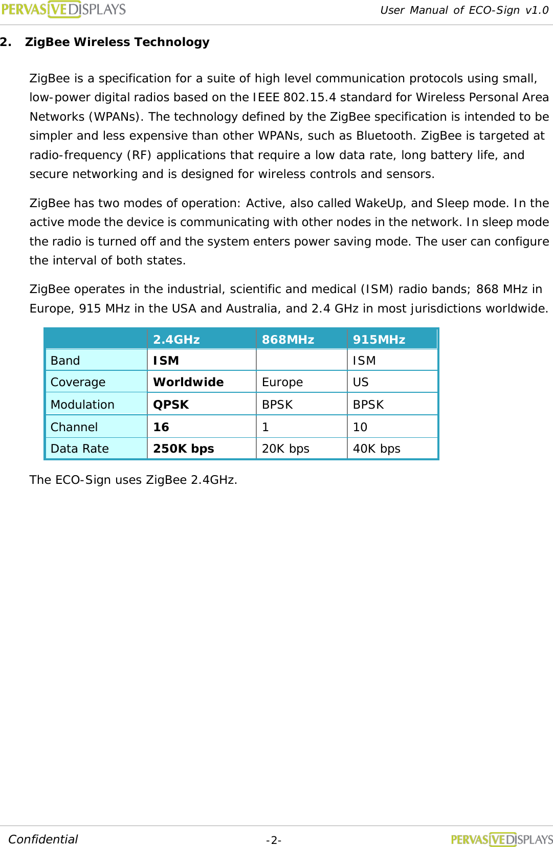
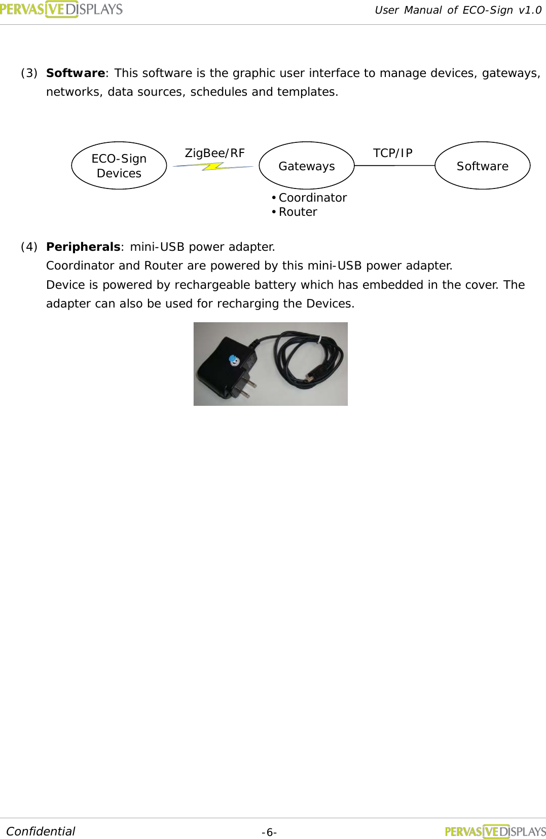
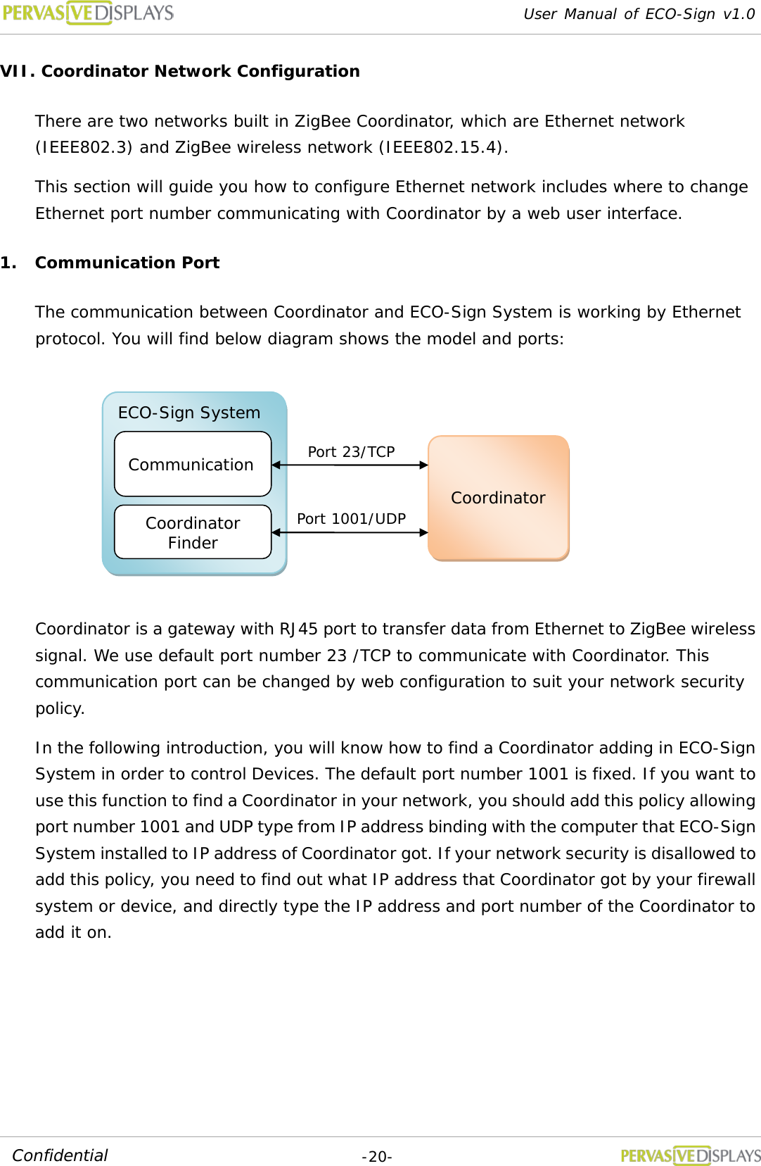
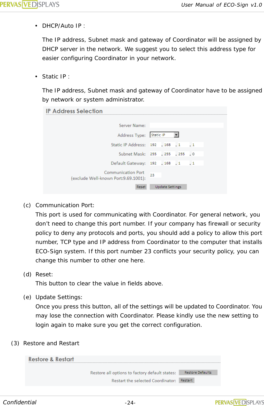
![User Manual of ECO-Sign v1.0 -10- Confidential IV. Quick Start with Template Design (1) Creating Templates: Creating a template is easy. Simple click the “New Template” radio button. Name the Template and select the size and the orientation from the drop down menus. Click [Next] to go to the drawing board to insert objects. (2) Configuring a Data Source: (a) In this example we configure the ECO-sign software to use Microsoft Access. Click the “Microsoft Access” and open the file browser by clicking the […] button. Browse to the location of mdb file and click “Test” to establish the connection. (b) Select the desired table from the drop down list. Database entries can now be inserted by clicking the Database icon on the drawing board. (c) Note: It’s only possible to have one database connection. The configuration connection applies to all Templates. (3) Using the Drawing board Insert objects by clicking the appropriate icon. Move objects to the desired position on the drawing board with your mouse. Use your mouse to resize the objects. Object attributes are described here e.g. size and resolution. Object properties are shown here. Browse image file path. Insert text and change the font type with a few clicks. Show barcode by given text and numbers.](https://usermanual.wiki/PERVASIVE-DISPLAYS/S0000AZ0R3/User-Guide-1586384-Page-13.png)
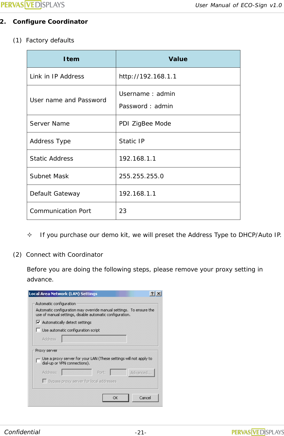
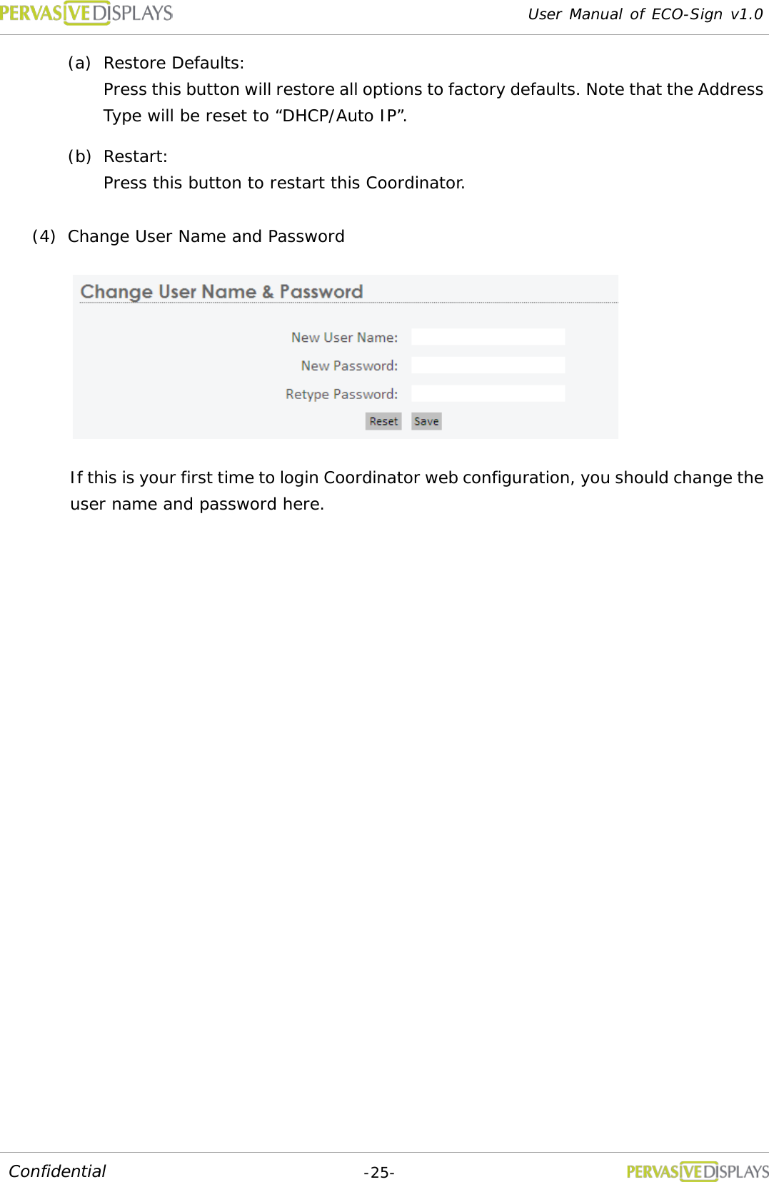
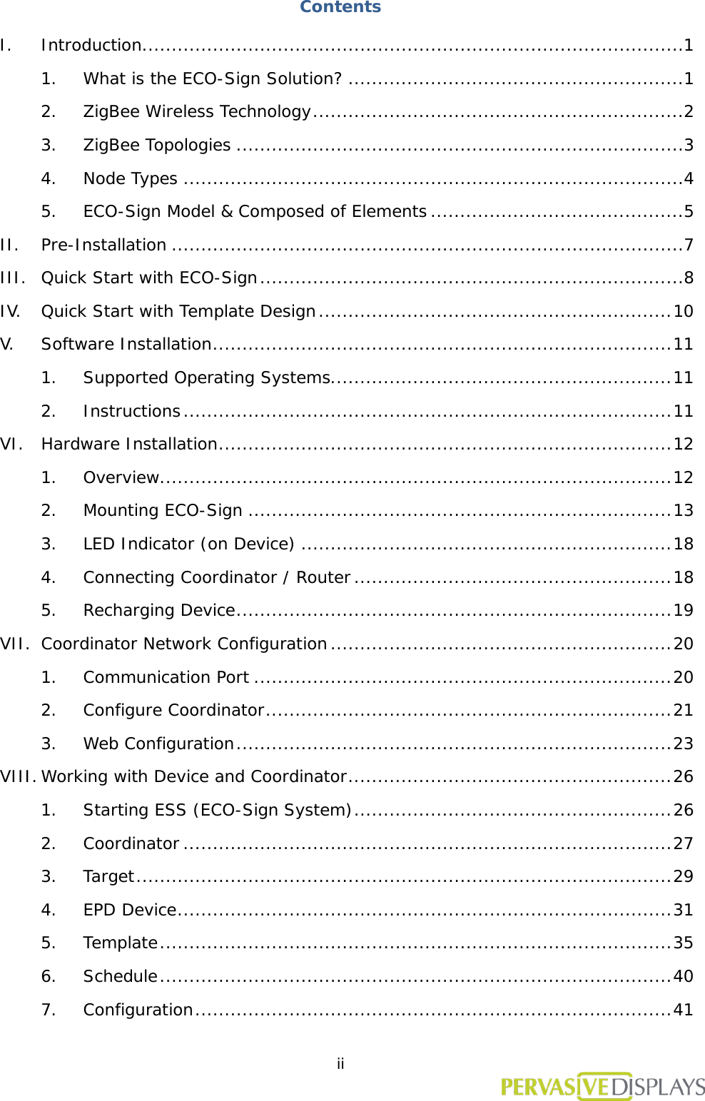
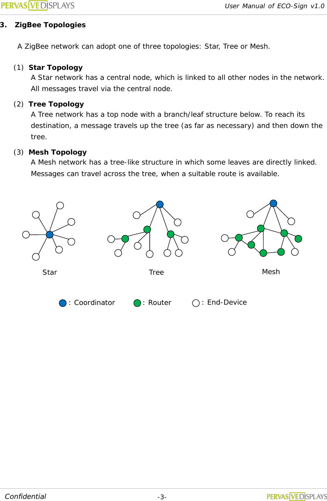
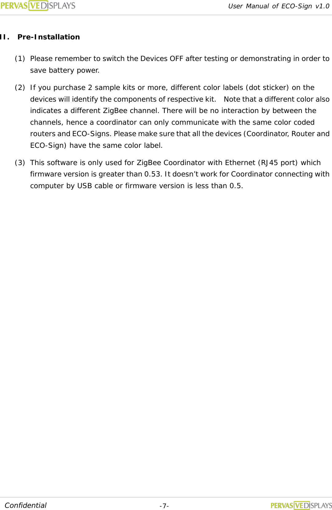
![User Manual of ECO-Sign v1.0 -27- Confidential 2. Coordinator After attaching a Coordinator to network, you have to register it in the list. To add a new Coordinator: (1) Click [Search] button. A new window “Coordinator Finder” will pop up. If the new Coordinator has joined the network correctly, it appears on the list, otherwise, please click [Refresh] button to search for it again or check the network cable of Coordinator. (2) Select the Check Box of each Coordinator which you want to add in the list for managing. Click [Select] button to exit the window.](https://usermanual.wiki/PERVASIVE-DISPLAYS/S0000AZ0R3/User-Guide-1586384-Page-30.png)
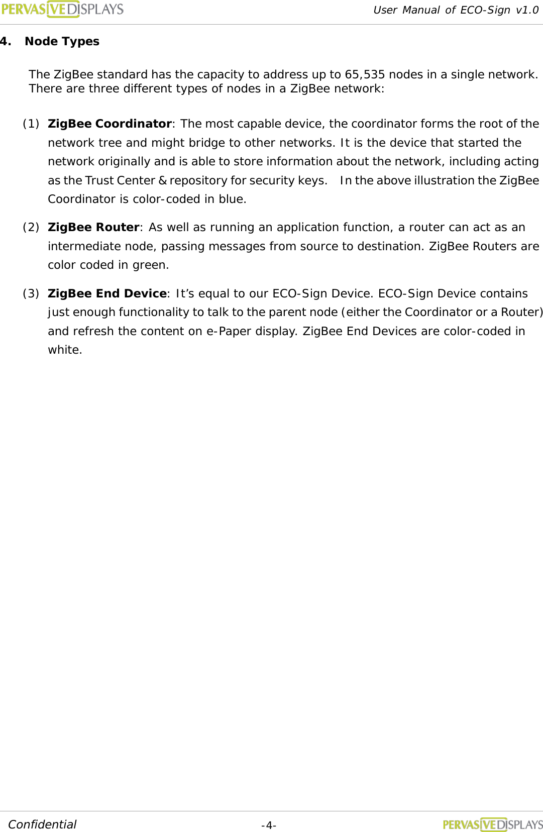
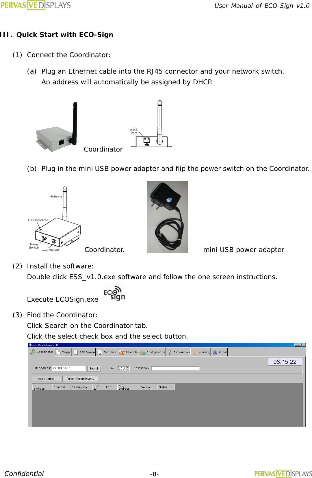
![User Manual of ECO-Sign v1.0 -28- Confidential (3) The new Coordinator will be listed on the grid. Please verify that the “Status” of the coordinator is “On”. (4) If you want to manual add a Coordinator, you can directly type the IP address of the Coordinator, the port number and the description. The default port number is 23 /TCP. How to change this port number, please find page.20 “VII.Configure Network Configuration”. To edit Coordinator: (1) The “Channel” and “Pan ID” are set to their default values in production. A firmware update is required to change the settings. The information will be updated automatically while Coordinator is working. (2) Click a list that you would like to edit. All of the data will be shown on the top fields. (3) It is not possible to change the IP address in the software. If you want to change the IP address contact your network administrator. (4) Press [Add/Update] button to finish editing data. To delete Coordinator: (1) Right click mouse button on a list that you would like to remove, press [Delete] to remove it.](https://usermanual.wiki/PERVASIVE-DISPLAYS/S0000AZ0R3/User-Guide-1586384-Page-31.png)
![User Manual of ECO-Sign v1.0 -29- Confidential 3. Target Target is an object that EPD Device can serve. A target name should be easy to understand with a meaningful name and description. For example, if you want to define a target for conference room M203 located in factory 2, building A on the 2nd floor, you could give the target name for “F2BAM203”. In the description field you can use “Factory 2, Building A, 2nd Floor, M203 meeting room”. To add a new Target: (1) Input a meaningful name and detail description of a new Target. (2) If you have not yet defined new schedule, you can select “Default” Schedule first. (3) Assign a Template to the Target. If you have not yet designed a suitable Template, you can select one of the preinstalled templates. You can always go back and change the template for the target at a later point. (4) Press [Add / Update] button to save the changes.](https://usermanual.wiki/PERVASIVE-DISPLAYS/S0000AZ0R3/User-Guide-1586384-Page-32.png)
![User Manual of ECO-Sign v1.0 -30- Confidential To edit Target: (1) Click an entry in the list; modify the data and then press [Add / Update] button. (2) Once the target name is the defined it cannot be changed. If you need to change the name you can delete the target and create a new one. To delete Target: (1) Right click mouse button on a list that you would like to remove, press [Delete] to remove it.](https://usermanual.wiki/PERVASIVE-DISPLAYS/S0000AZ0R3/User-Guide-1586384-Page-33.png)
![User Manual of ECO-Sign v1.0 -31- Confidential 4. EPD Device When a Device is switched ON or wakes up, the MAC address will be shown in the “Notification of EPD wakes up” field. If the EPD has not been registered, the message box of will show a Device named [unknown]. To register a device click the “Copy MAC” button select the size and target and click “Add/Update”. Note: the device only works with the same channel of Coordinator. Each field in the grid: MAC address : The MAC address of ECO-Sign Device which is a 23 character string in the ##-##-##-##-##-##-##-##, where # is a number [0-9] or a letter [A-F]. Status: Show the status of the Device i.e. “Wake Up” or “Sleep”. Target: The target the Device is assigned to. Next sleep: Shows the time when the Device will enter Sleep mode. Next wake up: Shows the time when the Device will enter Active mode. Battery: When the device wakes up, it will transmit the remaining power capacity to the software. When the value is between 5~10%, please recharge the Device. When the value is less than 1%, the ESS software will instruct the coordinator to stop sending data to the Device. The cell will be shown in red color.](https://usermanual.wiki/PERVASIVE-DISPLAYS/S0000AZ0R3/User-Guide-1586384-Page-34.png)
![User Manual of ECO-Sign v1.0 -32- Confidential This will also list a warning message in “Warning” tab strip. Coordinator IP: This Device is controlled by which Coordinator. Size: The size of Device. RSSI: Received Signal Strength Indication which is a measurement of the power present in a received radio signal. Signal Strength : (unit=dBm) 0 ~ -25 = Strong, -26 ~ -50 = Good, -51 ~ -75 = Fair, -76 ~ = Weak. “RSSI to D” means the signal strength from gateway to Device. “RSSI to C” means the signal strength back to Coordinator. When RSSI is less than -85 dBm, a router should be added between Coordinator and Device to enhance signal strength and distance. To add a new EPD Device: (1) There are two places to show the waked up message of EPD Device. One is shown in Information tab strip; another is at the top of this tab “Notification of EPD wakes up”. (2) When you switch ON a new Device, the MAC address will show in “Notification of EPD wakes up” box. Please click [Copy MAC] button and then the MAC address in “EPD information” will be copied. You can also directly type the MAC address here.](https://usermanual.wiki/PERVASIVE-DISPLAYS/S0000AZ0R3/User-Guide-1586384-Page-35.png)
![User Manual of ECO-Sign v1.0 -33- Confidential (3) Select right panel size of the Device. (4) Select a Target name for the EPD Device and assign it. (5) Click [Add / Update] button to add this EPD Device to list. When the EPD Device wakes up next time, the message will show correct Target name and work with Schedule accordingly. To edit a EPD Device: (1) Click a list that you would like to edit. Data will be shown on the top fields. (2) MAC address is the primary key which cannot be changed. (3) Press [Add/Update] button to finish editing data.](https://usermanual.wiki/PERVASIVE-DISPLAYS/S0000AZ0R3/User-Guide-1586384-Page-36.png)
![User Manual of ECO-Sign v1.0 -34- Confidential To delete EPD Device: (1) With your mouse right click on the EPD Device that you would like to remove and select [Delete] from the popup menu.](https://usermanual.wiki/PERVASIVE-DISPLAYS/S0000AZ0R3/User-Guide-1586384-Page-37.png)
![User Manual of ECO-Sign v1.0 -35- Confidential 5. Template ESS provides several objects and connectivity to design different content. Data Source: In this group, you just need to set the database connection from Microsoft SQL Server or Access one time. You can start to drag a database object on the layout and assign table schema by condition. If your data isn’t from a database, use the “Unused” radio button option. (1) Microsoft SQL Server: Please input a Microsoft SQL Server’s IP address/host name, login user ID, password and database name in the provided text fields. Click [Test] to test the connection. If the connection is successful, the Tables in the database will be listed in the drop-down list. (2) Microsoft Access: Click […] button to select an Access database file. The file path will be shown in the text box. If the Access database is password protected, please input it in the Password field.](https://usermanual.wiki/PERVASIVE-DISPLAYS/S0000AZ0R3/User-Guide-1586384-Page-38.png)
![User Manual of ECO-Sign v1.0 -36- Confidential Click [Test] to test the connection. If the connection is successful, the tables in the database will be listed in the drop-down list. Templates: 1. To add a new template: (1) Select the [New template] option button and name your template. (2) Select the size of Template. ESS only “7.4” and “10.2” templates are supported. (3) Select Direction. For example, 800x480 pixels is 7.4” landscape direction, 480x800 pixels is portrait direction. (4) Select the background color. The background color can be either black or white. (5) Click [Next] button, the template designer will appear on next screen. 2. To edit a template: (1) Select [Edit template] option button. (2) Click on a template that you would like to edit and click [Next] button then. (3) You can click each “Preview” button to see the final result immediately. The image will be opened by your system’s default image viewer.](https://usermanual.wiki/PERVASIVE-DISPLAYS/S0000AZ0R3/User-Guide-1586384-Page-39.png)
![User Manual of ECO-Sign v1.0 -37- Confidential 3. To delete a template: With your mouse right click on the template that you would like to remove and select [Delete] from the popup menu. Template Designer: 1. There are at least five objects to design the layout and setup of your template which are (1) Database (2) Image (3) Text (4) Microsoft Outlook and (5) Barcode object. 2. Each new object that you clicked will be added to the templates top-left position. You can press and hold your left mouse button to move the object to the desired position. You can also drag the borders of object to change the size 3. In object’s property area, you can change font, size or color. Database object: You can link a field from a data table of Microsoft SQL Server or Access database that you’ve set in previous step. The database object’s property looks like: WHERE clause: The WHERE clause is used for extracting the records that fulfill a specified criterion, likes WHERE string in SQL statement. It only supports “equal” operator to filter the result only one record fits. Text Object Image Object Database Object Object’s Property Design Area Object’s Information Outlook Object Barcode Object](https://usermanual.wiki/PERVASIVE-DISPLAYS/S0000AZ0R3/User-Guide-1586384-Page-40.png)
![User Manual of ECO-Sign v1.0 -38- Confidential Display field: The field to be shown on Device. Result: To show filtered record. Please make sure only one record is returned. If multiple records are return, you must redefine the WHERE clause. Press [Apply] to see the result on Template Image object: The image object’s property: You can import a .bmp, .jpg, or .png image file onto your template by pressing […] button. Press [Fit the background] button to scale your imported image to fit the entire background. Text object: The text object’s property: You can place any text object on the layout to act as a field name or type the string you want in the box. You also can press "..." button to import the content from a text file. Outlook object: The Microsoft Outlook object’s property: The field name are given from Microsoft Outlook. You can place the field you want onto the layout, and then the field will show data according to schedule. Barcode object: The Barcode object’s property: You can select the Symbology of barcode and input the data you would like to](https://usermanual.wiki/PERVASIVE-DISPLAYS/S0000AZ0R3/User-Guide-1586384-Page-41.png)
![User Manual of ECO-Sign v1.0 -39- Confidential show. If your barcode will show text under the barcode, “Show readable text” option should be checked. 4. If some objects are overlapping, you can right-click the object and choose to “Bring forward”, “Send backward”, “Bring to front” or “Send to back” on the pop-up menu. You can also use the "Delete" button to delete an object. 5. When you finish a template, please click [Next] button at the bottom-right position to preview the generated image. Otherwise, you can click [Previous] button to go back to the template list. 6. Several filters are provided to help you generate different effects. 7. The page shows the converted image. If okay, press [Finish] button back to template list.](https://usermanual.wiki/PERVASIVE-DISPLAYS/S0000AZ0R3/User-Guide-1586384-Page-42.png)
![User Manual of ECO-Sign v1.0 -40- Confidential 6. Schedule Schedule provides recurring and unconventional time intervals to configure the Device active or sleep modes. Recurring time interval 1. Please switch to “Configuration” page. You can set recurring time here. It is also the “Default” schedule which can be default selected in Target page to assign this schedule. 2. This setting is used for test or demo purpose. In real use case, we won’t allow Device frequently wakes up because it consumes much power. Unconventional time interval 1. In Schedule tab strip, it allows you to set unconventional time interval to wake up Devices. 2. Input a new Schedule name in the field and press [Add] button. 3. In the list box, click on the Schedule you just created. You can set the Wake-Up time in absolute time here. After pressing [Add] button, the new timing will be appended to right side list box. 4. To delete a timing: With your mouse right click on the time list that you would like to remove and select [Delete] from the popup menu.](https://usermanual.wiki/PERVASIVE-DISPLAYS/S0000AZ0R3/User-Guide-1586384-Page-43.png)
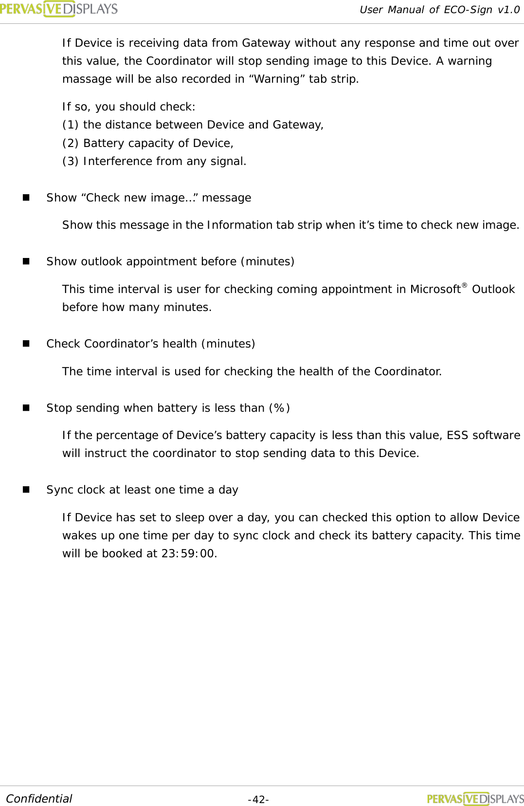
![User Manual of ECO-Sign v1.0 -41- Confidential 7. Configuration Default Schedule : (1) Like the setting above, the Device will wake up for 60 seconds. When it returns to sleep mode, it will keep sleeping for 60 seconds. (2) When the Device wakes up, it will check for a new image in the Coordinator. If the coordinator has an update to the display, the image will be transmitted immediately. Once the Device is finished receiving image from Coordinator, it will be assigned a new next wake up time and turns to sleep mode. (3) If a Coordinator is busy serving other Device, the 30 seconds is used to wait for Coordinator’s signal. If the waiting Device still can’t get any response from the Coordinator, it will turn to sleep mode. Check new image interval (seconds): When you change the Template of each Device, ESS has to create new content to be sent. This setting is to set the interval when ESS to generate new image. When it’s time to check new image, you can see a message “Checking new images …” is shown in Information tab strip. If any pixel was changed by user or data, ESS will generate new image for sending. A message likes “The image of [xxxxx] is ready to be sent [x].” is shown in Information tab strip as well. Time out of sending image (seconds): If Device is receiving data from Gateway but takes a long time without any response, you should set a time out to interrupt the transmission. 60 seconds is suggested of this sample setting for 7.4”. 90 seconds is for 10.2”. Stop sending when time out (times)](https://usermanual.wiki/PERVASIVE-DISPLAYS/S0000AZ0R3/User-Guide-1586384-Page-44.png)
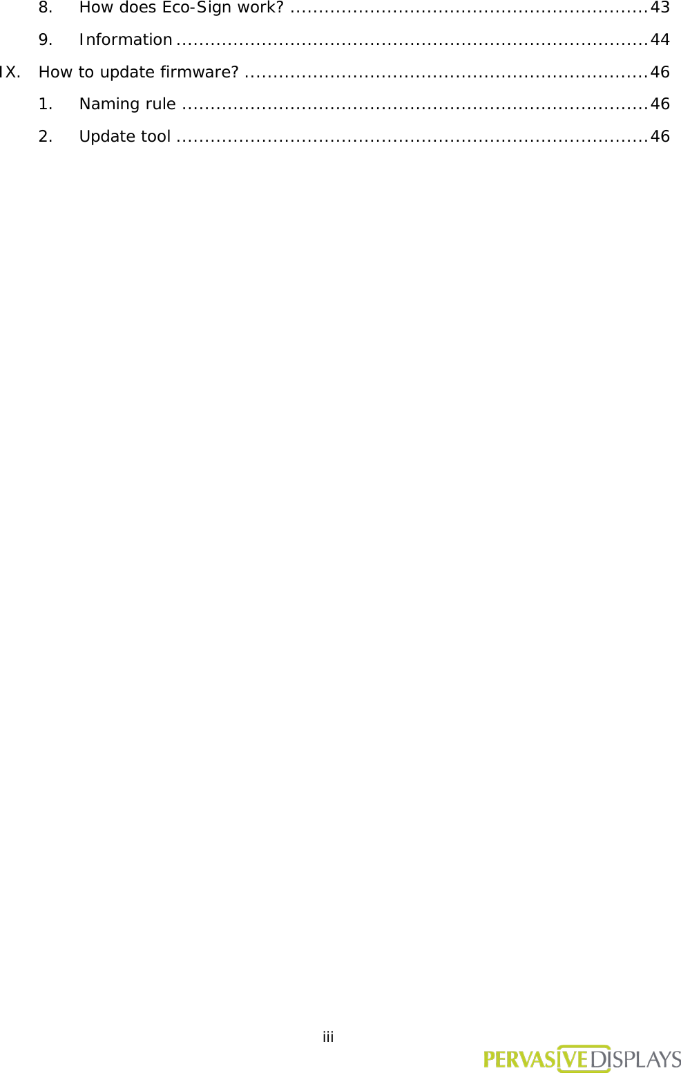
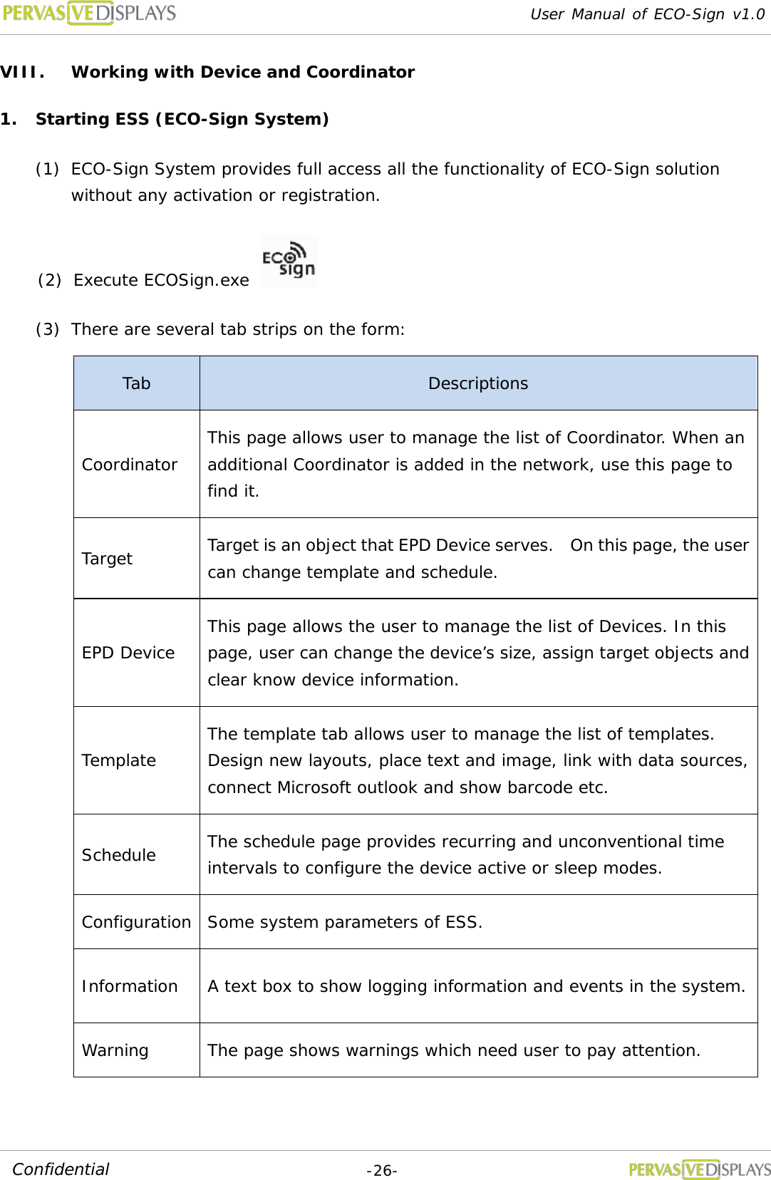
![User Manual of ECO-Sign v1.0 -44- Confidential 9. Information The message box shows the communication log of Coordinators and Devices. Below is an example. Message format: [HH:MM:SS]: [Information] Item Description Log 1 Coordinator is working. 14:19:23 Coordinator [10.200.34.29] is connected successfully. 2 Switch ON Device sequentially. Whatever Device wakes up first time, ESS will force Devices queued up to set next wake up time and turn to sleep. 14:19:57 Agent Reply: Checking new images... 14:20:49 [Demo1]: Wake up. MAC=[00-12-4b-00-01-13-ce-1d] , RSSI to D=-30db, RSSI back to C=-51db 14:20:49 [Demo1]: Set up next wakeup time:2011/04/28 14:25:18 14:20:52 [Demo1]: Next WakeUp time=2011/04/28 14:25:18 14:20:54 [Demo1]: Device returns to sleep mode. 14:21:00 Agent Reply: Checking new images... 14:22:06 Agent Reply: Checking new images... 14:22:19 [Demo2]: Wake up. MAC=[00-12-4b-00-01-13-cf-64] , RSSI to D=-23db, RSSI back to C=-41db 14:22:19 [Demo2]: Set up next wakeup time:2011/04/28 14:26:48 14:22:23 [Demo2]: Next WakeUp time=2011/04/28 14:26:48 14:22:24 [Demo2]: Device returns to sleep mode. 14:23:10 Agent Reply: Checking new images... 14:23:50 [Demo3]: Wake up. MAC=[00-12-4b-00-01-13-cf-41] , RSSI to D=-39db, RSSI back to C=-59db 14:23:50 [Demo3]: Set up next wakeup time:2011/04/28 14:28:18 14:23:53 [Demo3]: Next WakeUp time=2011/04/28 14:28:18 14:23:54 [Demo3]: Device returns to sleep mode. 3 Time to generate new image. You can find “Configuration” page “Check new image interval (minutes)” to set this timer. You can uncheck「Show “Check new image…” message」not to show this message. 14:24:13 Agent Reply: Checking new images... 14:25:18 Agent Reply: Checking new images... 4 You can check the wake up timing at item 3 that had marked by different color. At item 2, the new images were generated. When Device wakes up, ESS will 14:25:19 [Demo1]: Wake up. MAC=[00-12-4b-00-01-13-ce-1d] , RSSI to D=-31db, RSSI back to C=-51db 14:25:22 The image of [Demo1] is ready to be sent [5]. 14:25:25 Ready to send image... 14:25:26 [Demo1]: Receiving image... 14:25:42 [Demo1]: Image has been transmitted! 14:25:42 [Demo1]: Set up next wakeup time:2011/04/28 14:29:48 14:25:45 [Demo1]: Next WakeUp time=2011/04/28 14:29:48](https://usermanual.wiki/PERVASIVE-DISPLAYS/S0000AZ0R3/User-Guide-1586384-Page-47.png)
![User Manual of ECO-Sign v1.0 -45- Confidential transmit the image to Device immediately. “Receiving image...” means Coordinator is transmitting image to Device. Once the image is transferred completely, you will find “Image has been transmitted!” message and the Device is rescheduled to next wake up time. Turn to sleep then. 14:25:47 [Demo1]: Device returns to sleep mode. 14:26:21 Agent Reply: Checking new images... 14:26:48 [Demo2]: Wake up. MAC=[00-12-4b-00-01-13-cf-64] , RSSI to D=-24db, RSSI back to C=-43db 14:26:53 The image of [Demo2] is ready to be sent [4]. 14:26:56 Ready to send image... 14:26:56 [Demo2]: Receiving image... 14:27:12 [Demo2]: Image has been transmitted! 14:27:12 [Demo2]: Set up next wakeup time:2011/04/28 14:31:18 14:27:15 [Demo2]: Next WakeUp time=2011/04/28 14:31:18 14:27:16 [Demo2]: Device returns to sleep mode. 14:27:25 Agent Reply: Checking new images... 14:28:19 [Demo3]: Wake up. MAC=[00-12-4b-00-01-13-cf-41] , RSSI to D=-46db, RSSI back to C=-66db 14:28:23 The image of [Demo3] is ready to be sent [2]. 14:28:26 Ready to send image... 14:28:26 [Demo3]: Receiving image... 14:28:29 Agent Reply: Checking new images... 14:28:45 [Demo3]: Image has been transmitted! 14:28:45 [Demo3]: Set up next wakeup time:2011/04/28 14:32:48 14:28:49 [Demo3]: Next WakeUp time=2011/04/28 14:32:48 14:28:51 [Demo3]: Device returns to sleep mode. 5 You can also check the “Next WakeUp timing” in item 4 that had marked by different color. Devices are going to work to follow such rule in the future. If the image was not transmitted successfully, it will show “Time out of transmitting image” in the message box. You could find the time out setting at “Configuration” page “Time out of sending image (seconds)”. 14:29:32 Agent Reply: Checking new images... 14:29:49 [Demo1]: Wake up. MAC=[00-12-4b-00-01-13-ce-1d] , RSSI to D=-37db, RSSI back to C=-57db 14:29:54 The image of [Demo1] is ready to be sent [6]. 14:29:57 Ready to send image... 14:29:57 [Demo1]: Receiving image... 14:30:13 [Demo1]: Image has been transmitted! 14:30:13 [Demo1]: Set up next wakeup time:2011/04/28 14:34:18 14:30:17 [Demo1]: Next WakeUp time=2011/04/28 14:34:18 14:30:18 [Demo1]: Device returns to sleep mode. 14:30:37 Agent Reply: Checking new images... 14:31:19 [Demo2]: Wake up. MAC=[00-12-4b-00-01-13-cf-64] , RSSI to D=-25db, RSSI back to C=-44db 14:31:24 The image of [Demo2] is ready to be sent [3]. 14:31:27 Ready to send image... 14:31:27 [Demo2]: Receiving image... 14:31:40 Agent Reply: Checking new images... 14:31:43 [Demo2]: Image has been transmitted! 14:31:43 [Demo2]: Set up next wakeup time:2011/04/28 14:35:48 14:31:46 [Demo2]: Next WakeUp time=2011/04/28 14:35:48 14:31:47 [Demo2]: Device returns to sleep mode. 14:32:44 Agent Reply: Checking new images... 14:32:50 [Demo3]: Wake up. MAC=[00-12-4b-00-01-13-cf-41] , RSSI to D=-39db, RSSI back to C=-57db 14:32:54 The image of [Demo3] is ready to be sent [5]. 14:32:57 Ready to send image... 14:32:57 [Demo3]: Receiving image... 14:33:11 [Demo3]: Image has been transmitted! 14:33:11 [Demo3]: Set up next wakeup time:2011/04/28 14:37:18 14:33:14 [Demo3]: Next WakeUp time=2011/04/28 14:37:18 14:33:15 [Demo3]: Device returns to sleep mode.](https://usermanual.wiki/PERVASIVE-DISPLAYS/S0000AZ0R3/User-Guide-1586384-Page-48.png)
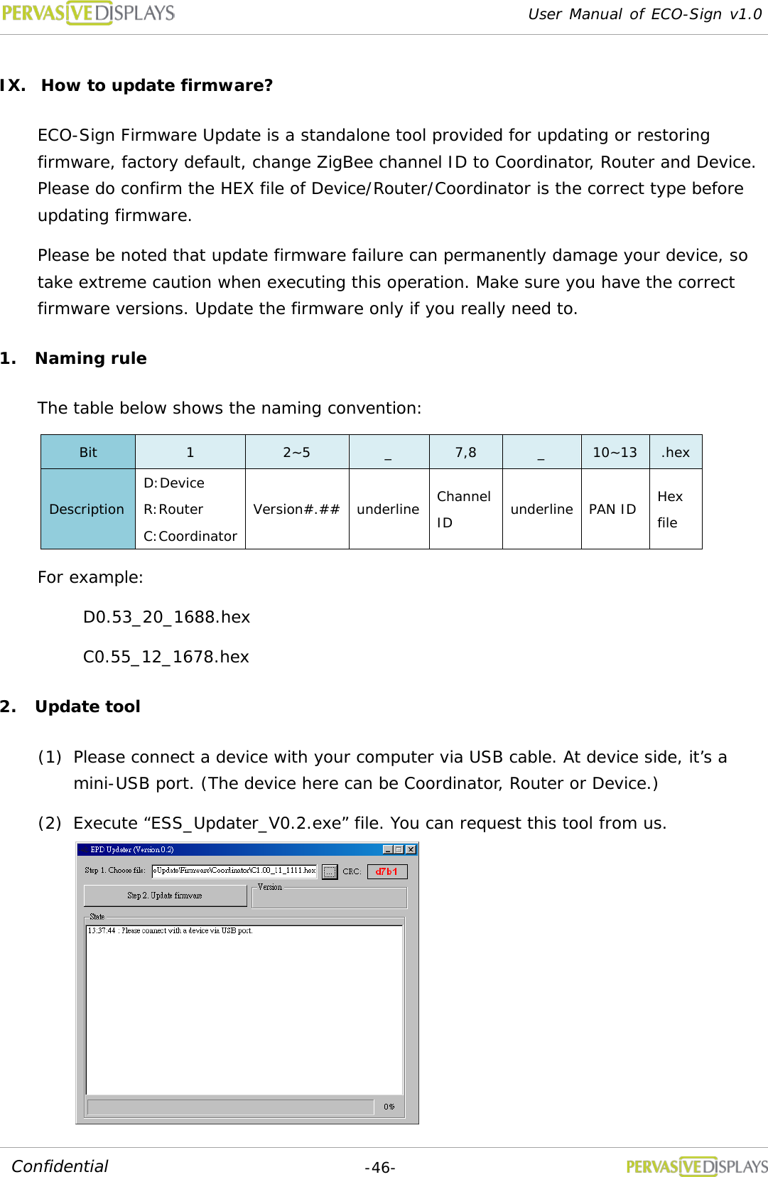
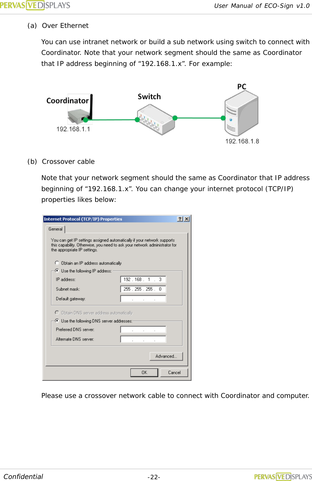
![User Manual of ECO-Sign v1.0 -47- Confidential (3) Choose a HEX file that you would like to update. Please do check it matches the device type in advance. After choosing the correct HEX file, the form will show a CRC number. (4) Please switch the device ON. (5) Click [Step 2. Update Firmware] button to start updating the new firmware. The current firmware version of device is shown in “Version” area: (6) You will be asked to switch the device OFF and ON again. Please proceed. (7) After switching the device ON, the tool is going to start updating firmware. Please wait for the message “Verifying the firmware code...OK (Elapsed time: 00:00:##)”. If failed, if the update fails repeat step (2). (8) You’ll be asked to power cycle the device again. Please proceed. (9) When you return to the tool, you will find the new firmware version. (10) Switch OFF the device and exit the tool. The device is updated successfully.](https://usermanual.wiki/PERVASIVE-DISPLAYS/S0000AZ0R3/User-Guide-1586384-Page-50.png)