PYRESCOM 3XX090601 RFID Reader User Manual
PYRESCOM RFID Reader Users Manual
UserManual.wiki
>
PYRESCOM
>
3XX090601 User Manual
Users Manual
Navigation menu
Upload a User Manual
Namespaces
Wiki Guide
HTML
PDF
Info
Views
User Manual
Discussion / Help
Navigation
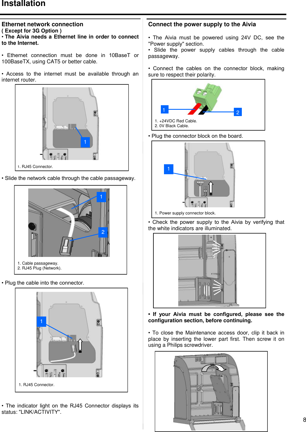
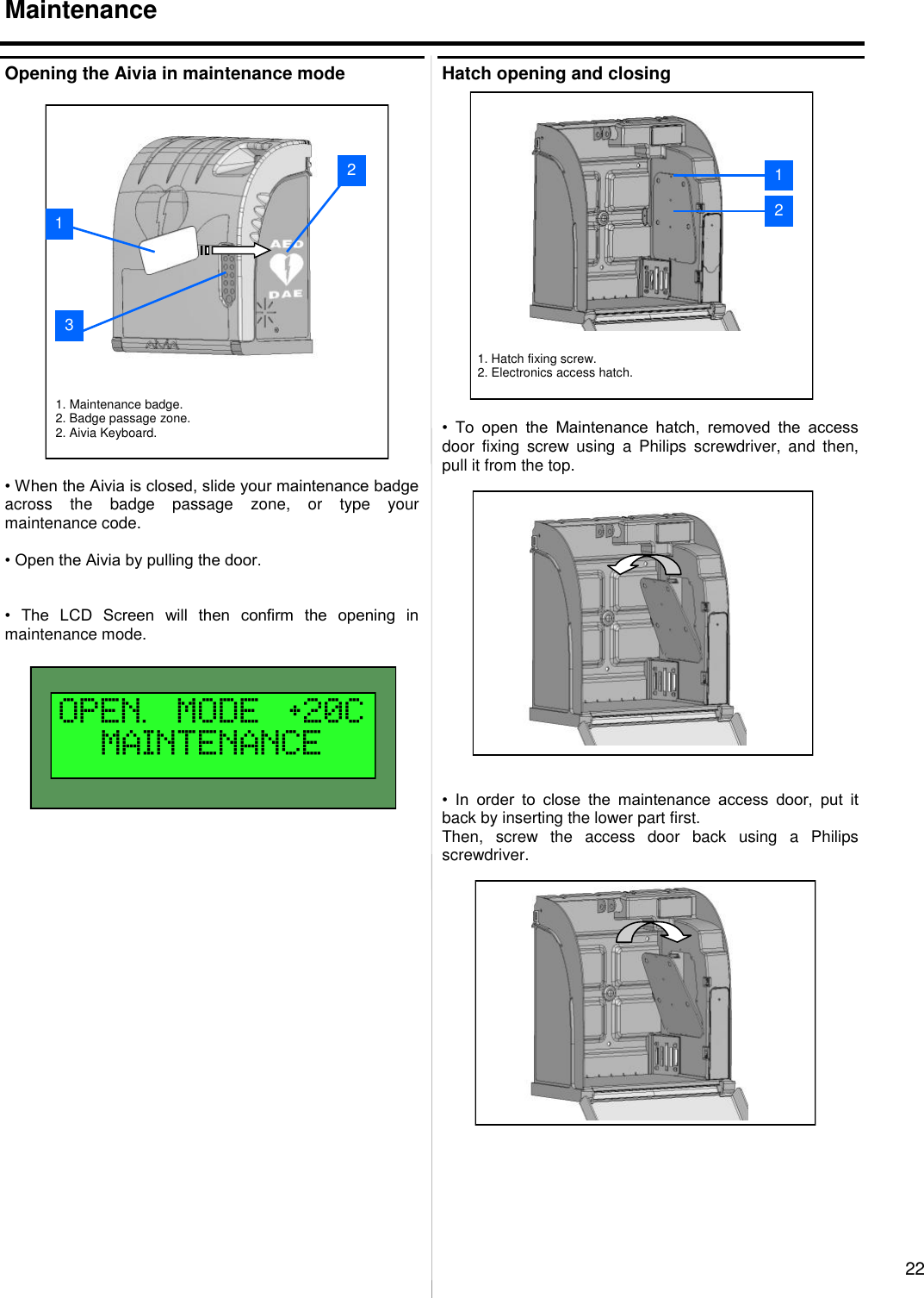
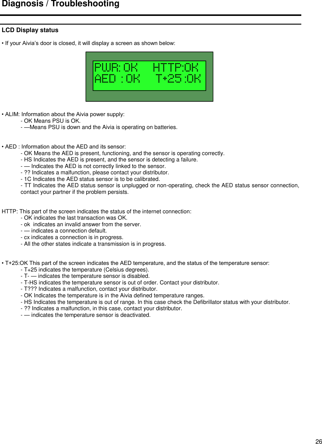
![12 Configuration Grayed out zones [1] indicate an option you do not have on your Aivia. Checkboxes, [2] Allow you to enable or disable functions of your Aivia. • You can edit all the available fields. We will now explain their meanings. Intercom: • Disabling the Intercom will prevent the Aivia from calling Emergencies services. In this case, all the error codes linked to Intercom features will not be displayed. • Number 1: First phone number to be called in case of emergencies or when the call button is pressed. This phone number is mandatory. • Number 2: If the first number cannot be reached, the second phone number will be called. • GSM–3G: PIN Code : PIN Code from the SIM card inserted into the Aivia. • Call Option: • On Opening Door: Call is emitted on door opening. • On AED Taken Off: Call is emitted when the AED sensor is taken off. • Call Button: The call button can work in three different ways : • Disabled: Disabled, door opening mandatory. • Enabled : One press calls emergencies. • Enabled / Confirmation: Second press necessary in the 10 following seconds to make the call. • Automatic opening: In seconds. Delay to the automatic unlocking of the Aivia during a call. • DTMF Code: Enables the Aivia to be unlocked from a distance using this code. 1. Greyed out zone. 2. Available checkbox. 2 1](https://usermanual.wiki/PYRESCOM/3XX090601/User-Guide-2709533-Page-12.png)