PayRange 00370 PayRange Blukey Module User Manual
PayRange Inc. PayRange Blukey Module
UserManual.wiki
>
PayRange
>
00370 User Manual
User Manual
Navigation menu
Upload a User Manual
Namespaces
Wiki Guide
HTML
PDF
Info
Views
User Manual
Discussion / Help
Navigation
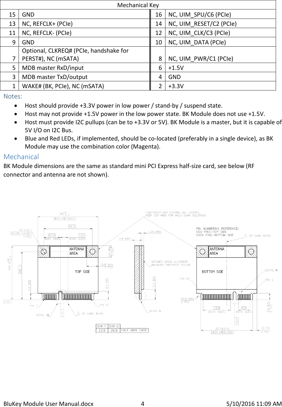
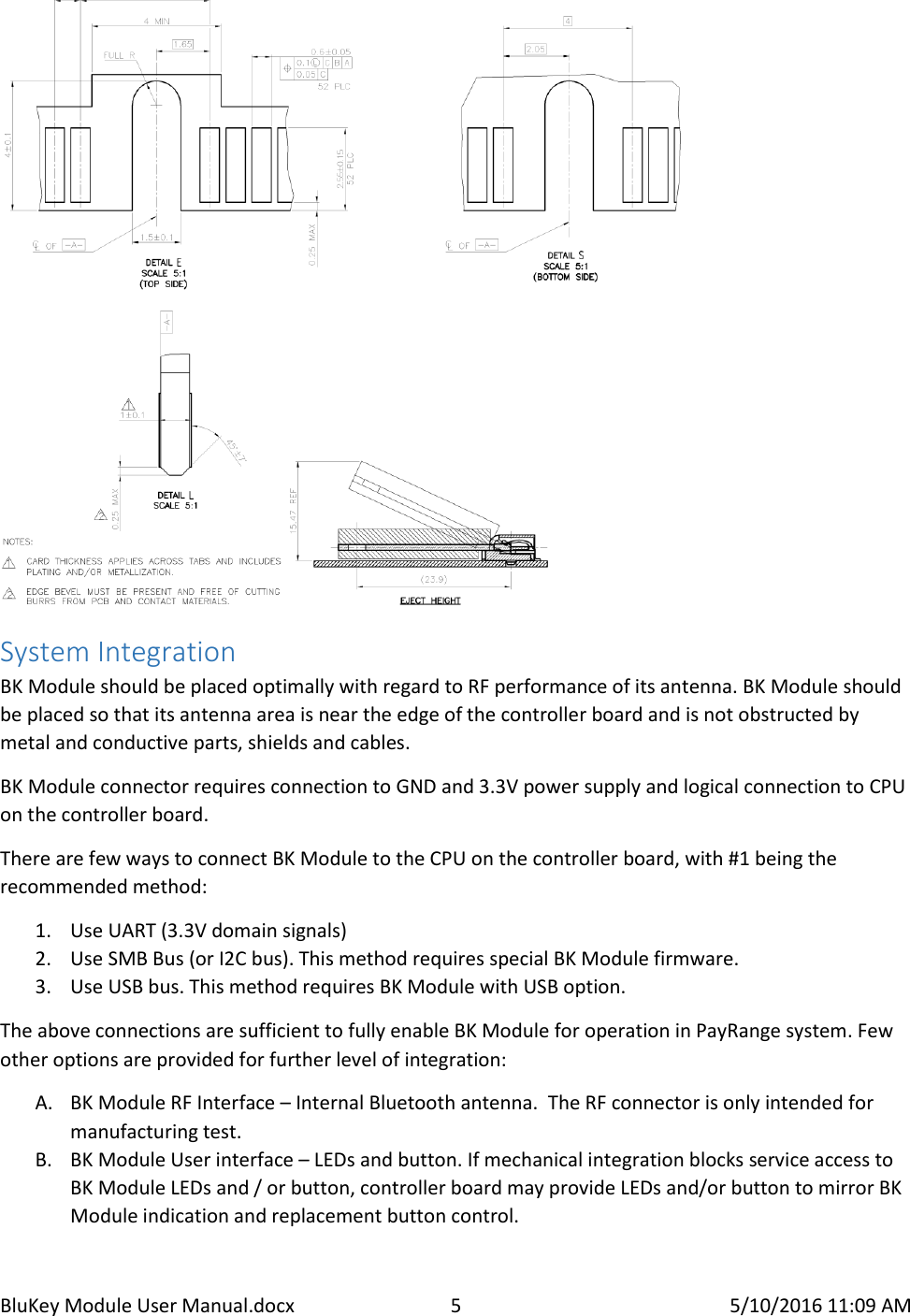
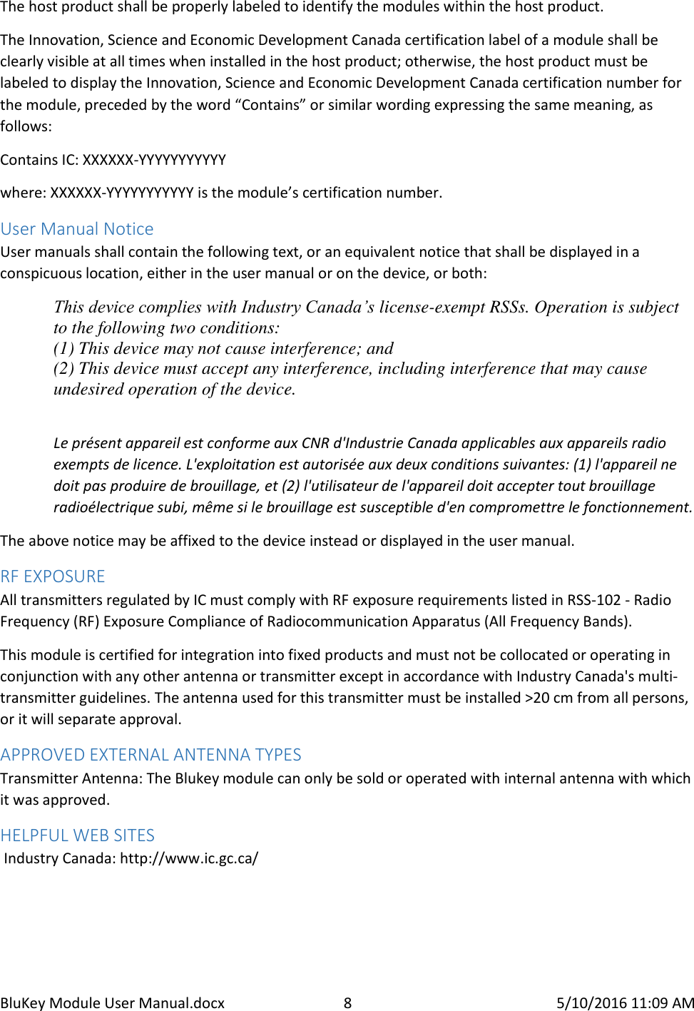
![BluKey Module User Manual.docx 3 5/10/2016 11:09 AM 21 GND power 22 [PERST#] input 19 UART_AUX_TxD output 20 [W_DISABLE#] input 17 UART_AUX_RxD input 18 GND power Mechanical Key 15 GND power 16 Reserved NC 13 Reserved NC 14 Reserved NC 11 Reserved NC 12 Reserved NC 9 GND power 10 Reserved NC 7 [CLKREQ#] output, open drain 8 Reserved NC 5 UART_TxD output 6 +1.5V power 3 UART_RxD input 4 GND power 1 [WAKE#] output, open drain 2 +3.3V power Host Device Design Requirements All signals are in +3.3V domain. The following table lists requirements for each pin. Pin Notes Pin Notes 51 NC, detect mSATA if GND 52 +3.3V 49 Optional, connect to a button dedicated to BK function (other end to GND), mSATA: DA/DSS 50 GND 47 NC, Vendor (mSATA) 48 +1.5V 45 NC, Vendor (mSATA) 46 Optional, Blue LED for BK status, max 9mA, Vol 400mV 43 NC, detect mini PCIe if GND 44 Optional, Red LED for BK status, max 9mA, Vol 400mV 41 +3.3V 42 Optional, LED 3 for BK status, max 9mA, Vol 400mV 39 +3.3V 40 GND 37 GND 38 USB_D+ master / hub 35 GND 36 USB_D- master / hub 33 NC, PETp0 (PCIe), +A (mSATA) 34 GND 31 NC, PETn0 (PCIe), -A (mSATA) 32 Optional, I2C_SDA (slaves only), provide pullup* 29 GND 30 Optional, I2C_SCL (slaves only), provide pullup* 27 GND 28 +1.5V 25 NC, PERp0 (PCIe), -B (mSATA) 26 GND 23 NC, PERn0 (PCIe), +B (mSATA) 24 +3.3V 21 GND 22 Optional, PERST# (PCIe), NC (mSATA) 19 NC or 2nd MDB, UIM_IC_DP (PCIe) 20 Optional, W_DISABLE1# (PCIe), NC (mSATA) 17 NC or 2nd MDB, UIM_IC_DM (PCIe) 18 GND](https://usermanual.wiki/PayRange/00370/User-Guide-2988992-Page-3.png)