Philips Medical Systems North America MX40WLAN2 INTELLIVUE MX40 WLAN2 PATIENT WORN DEVICE User Manual MX40 IFU Athens
Philips Medical Systems North America Co. INTELLIVUE MX40 WLAN2 PATIENT WORN DEVICE MX40 IFU Athens
UserManual.wiki
>
Philips Medical Systems North America
>
MX40WLAN2 User Manual
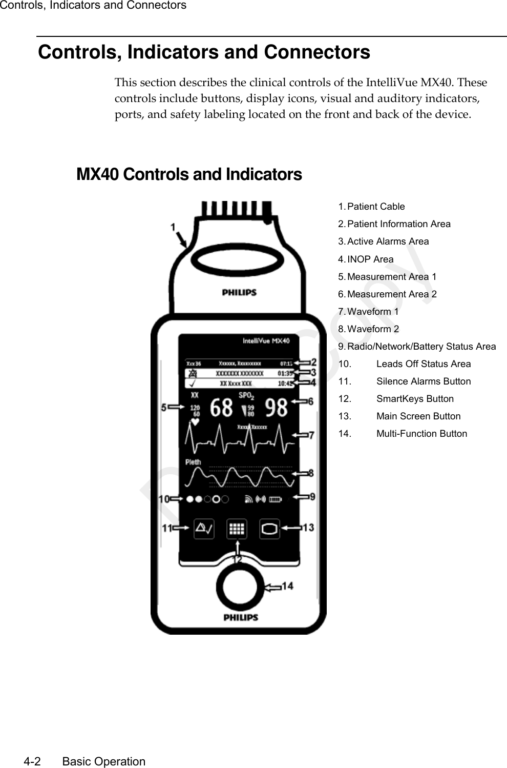
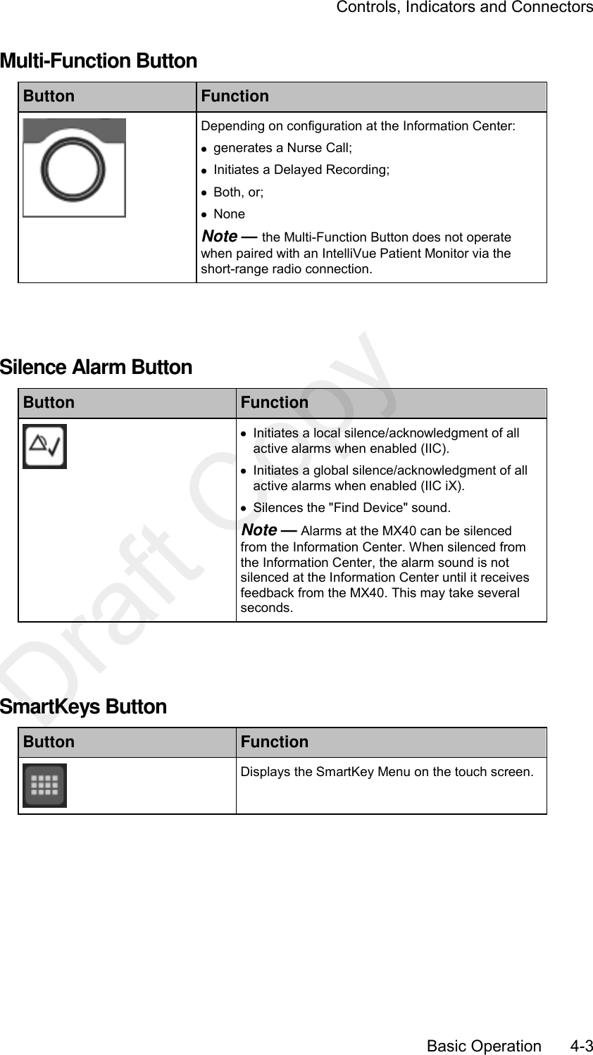
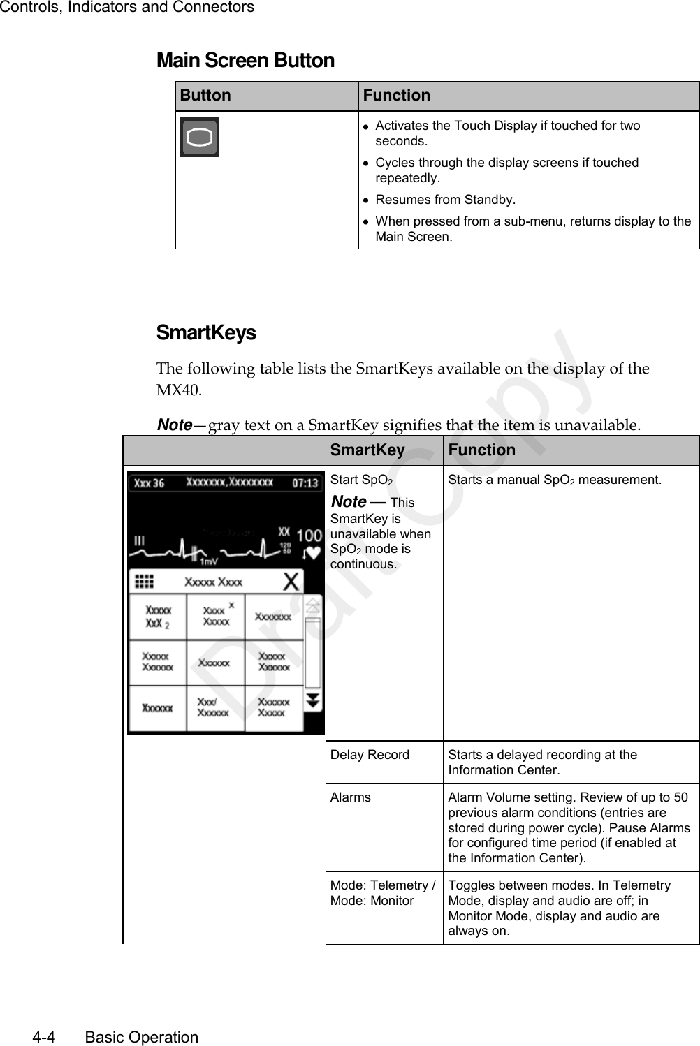
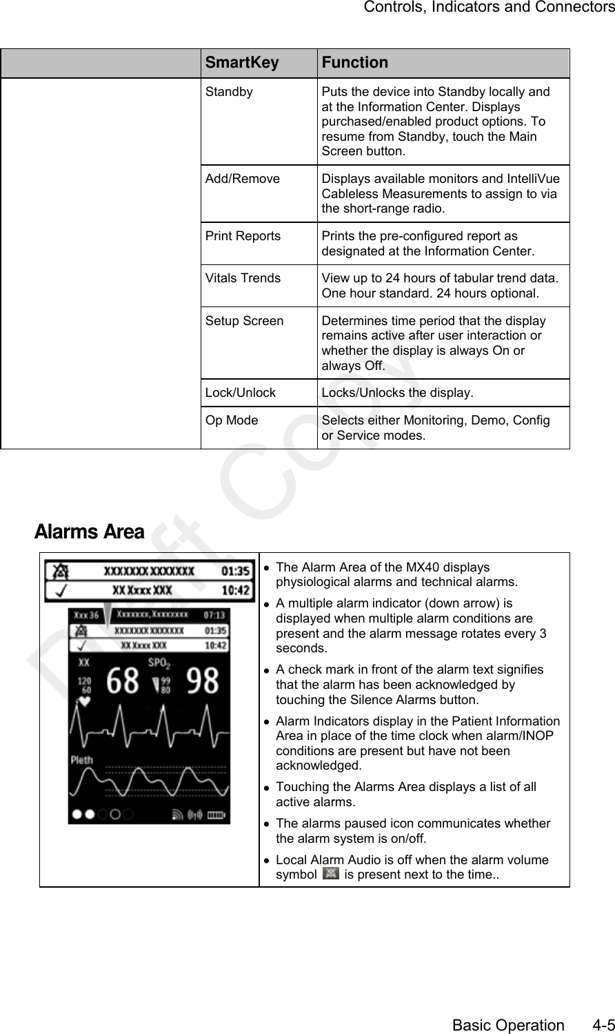
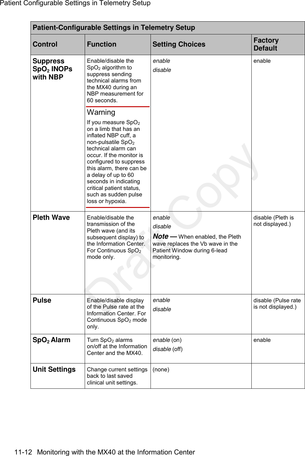
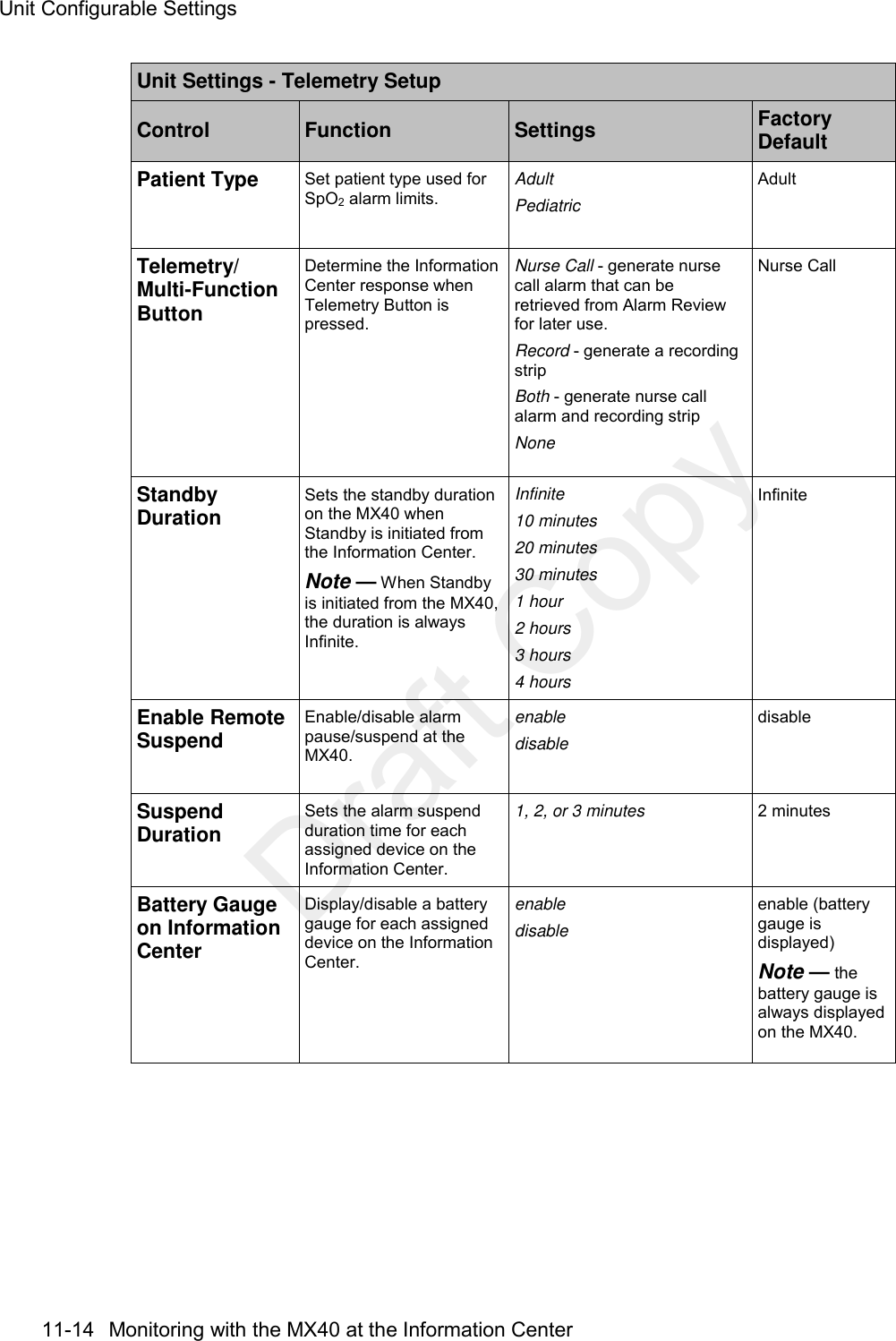
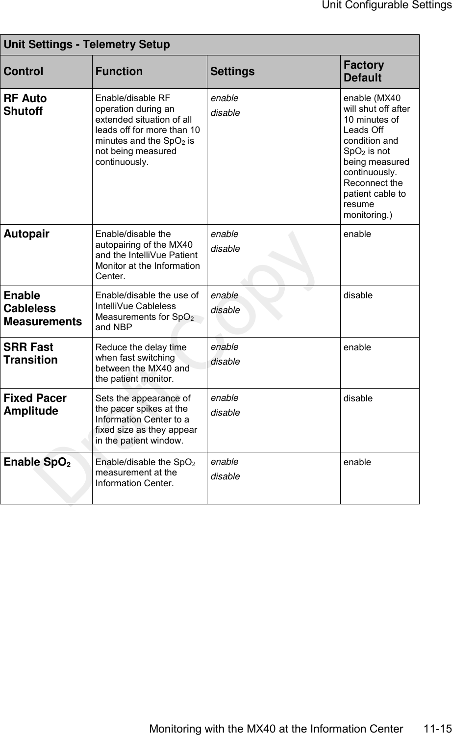
USERS MANUAL
Navigation menu
Upload a User Manual
Namespaces
Wiki Guide
HTML
PDF
Info
Views
User Manual
Discussion / Help
Navigation