Philips Medical Systems North America SRRBV1 Short Range Radio Module User Manual m81059001c
Philips Medical Systems North America Co. Short Range Radio Module m81059001c
Contents
- 1. User Manual MP5 and MP5T
- 2. User Manual MP2
- 3. User Manual X2
- 4. User Manual Olympus
- 5. User Manual Saturn
- 6. User Manual
User Manual MP5 and MP5T


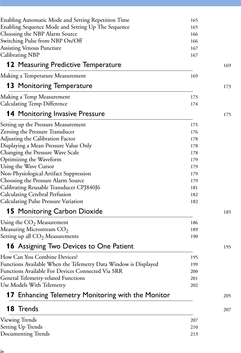

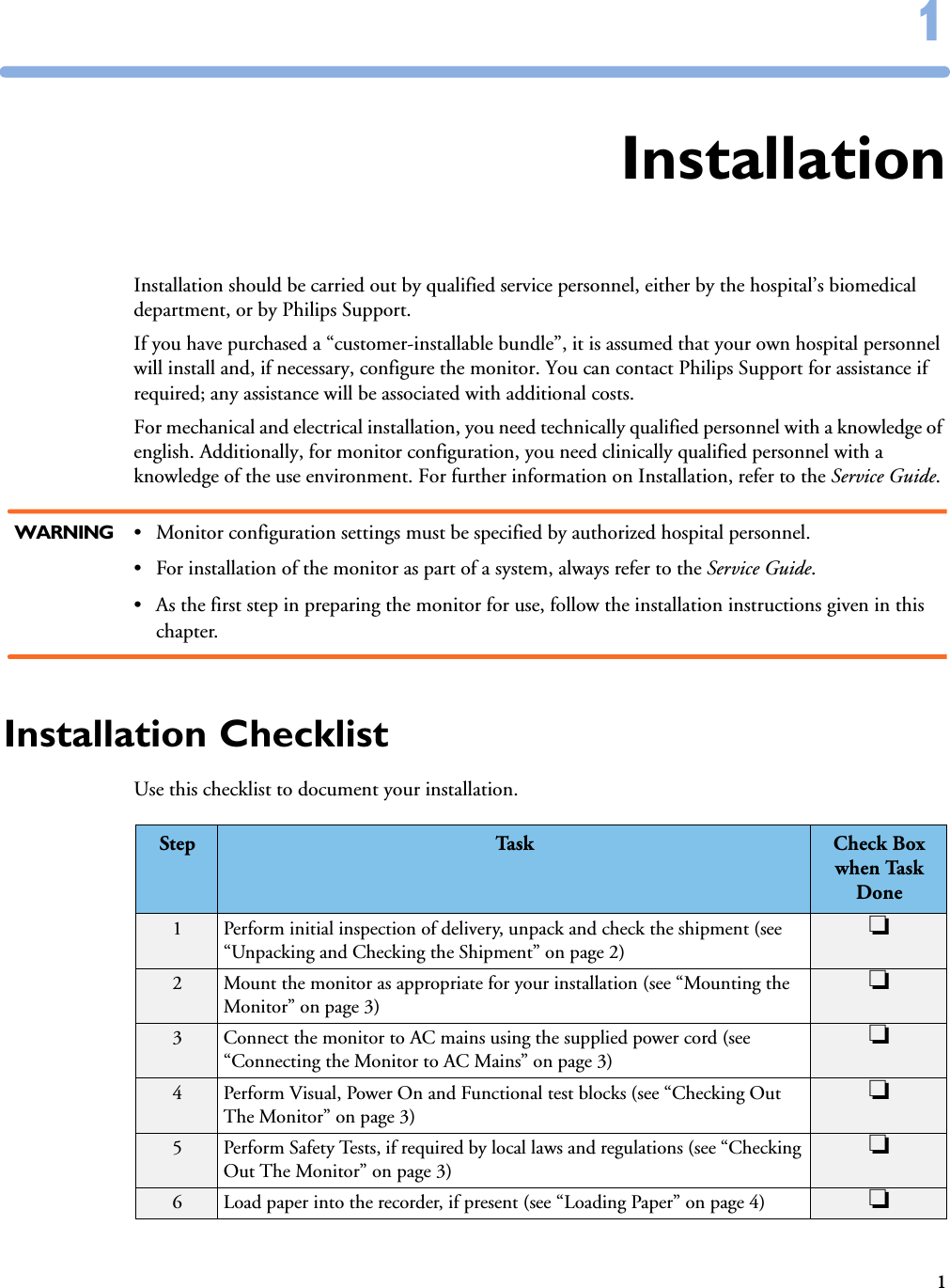
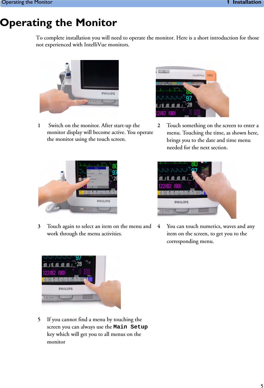


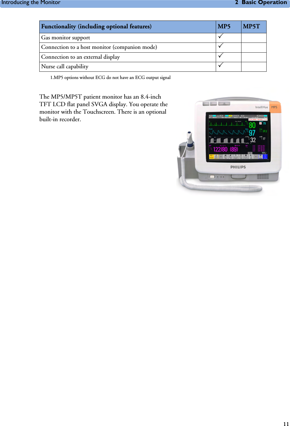

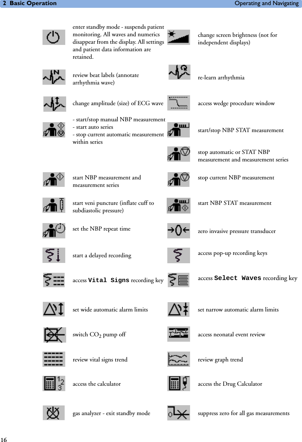
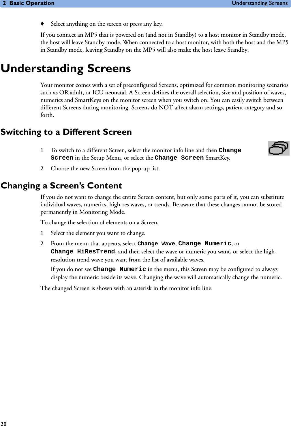

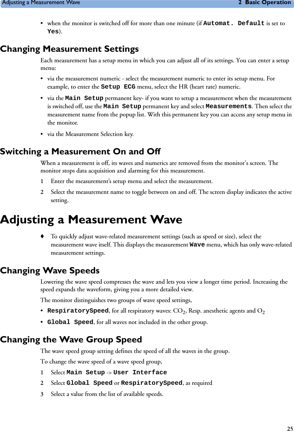
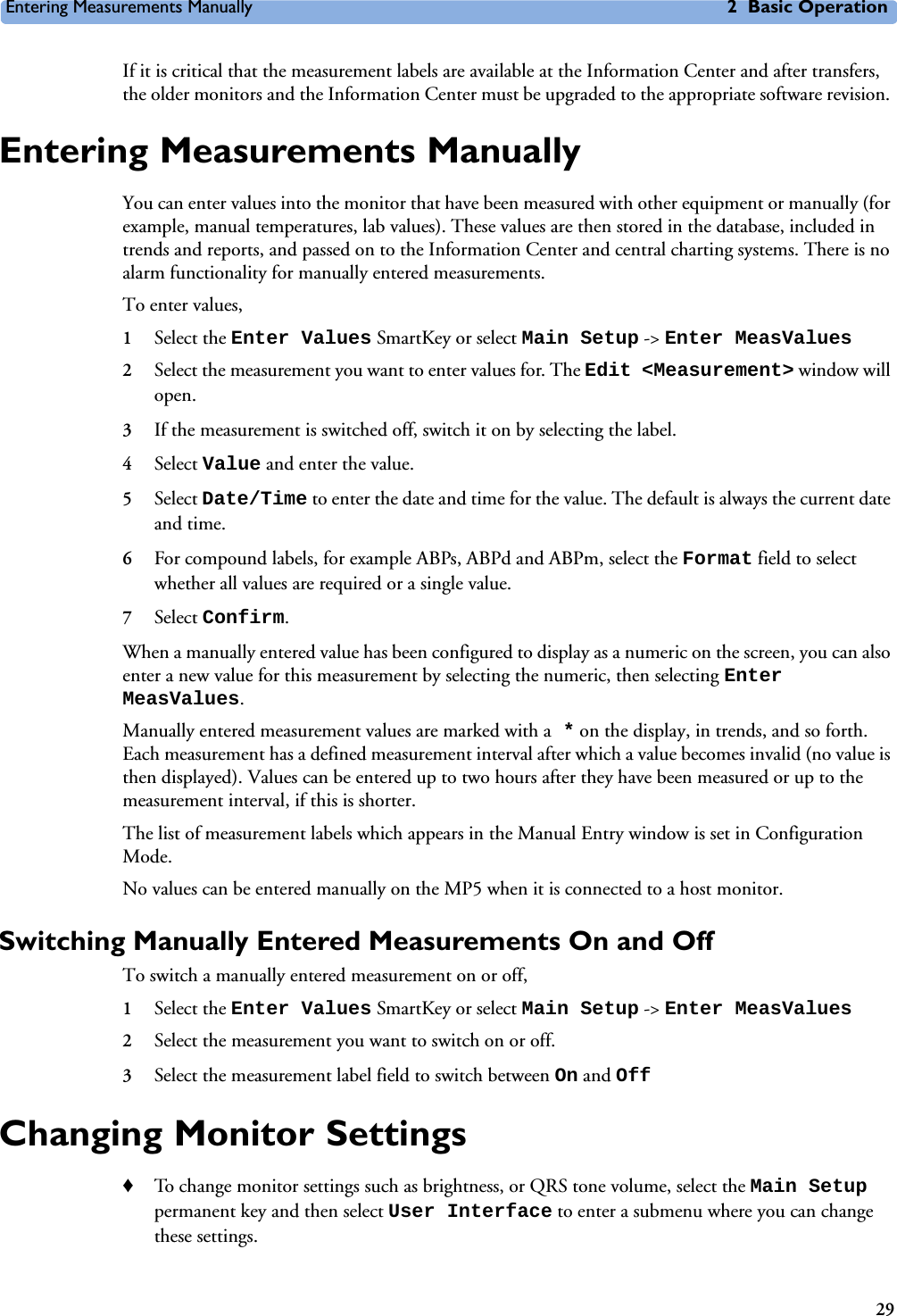
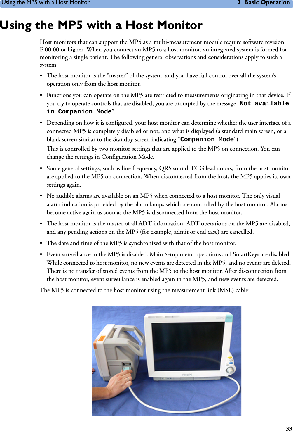


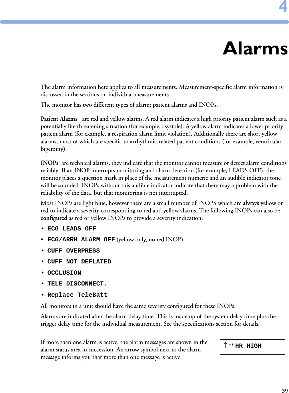
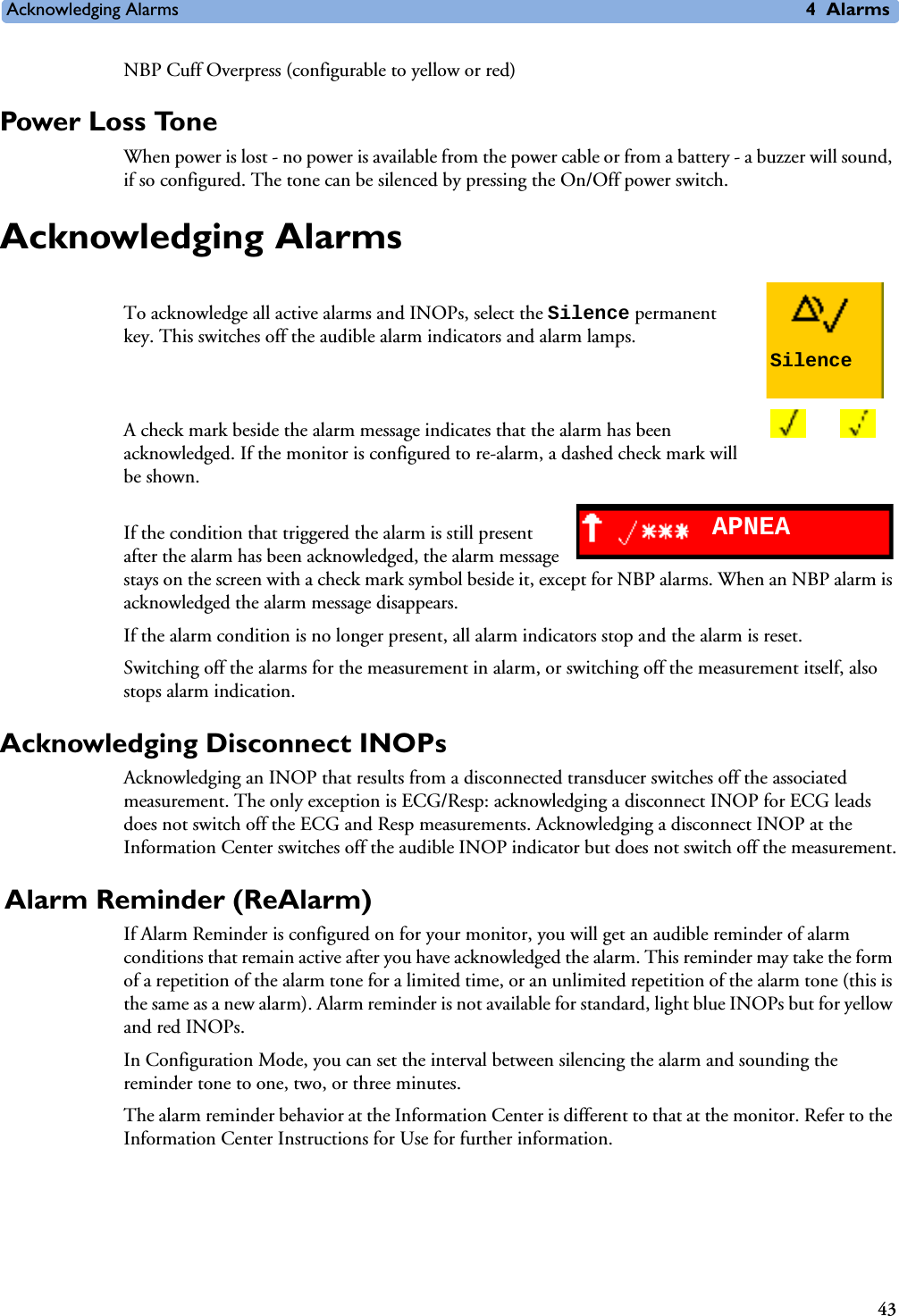
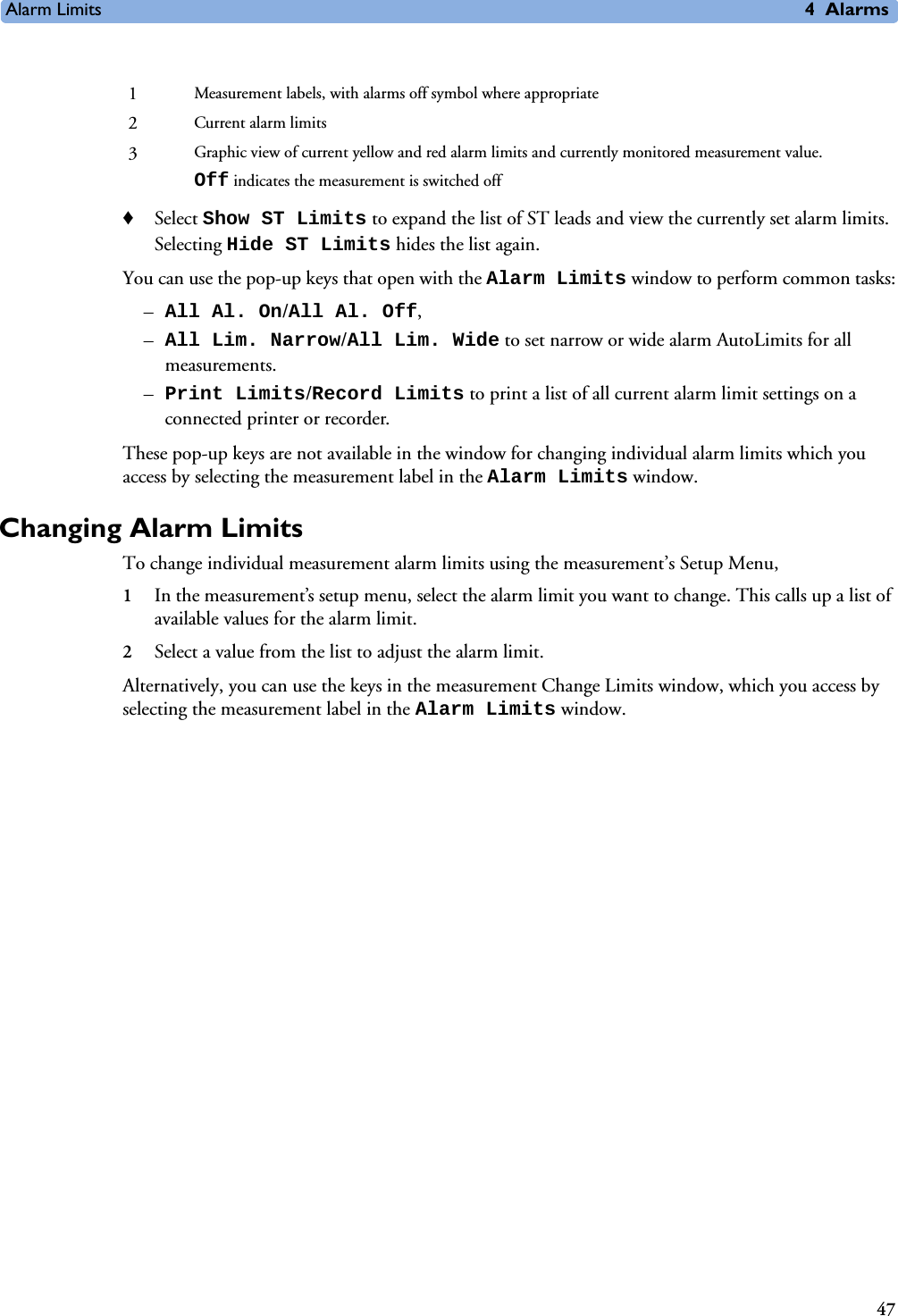
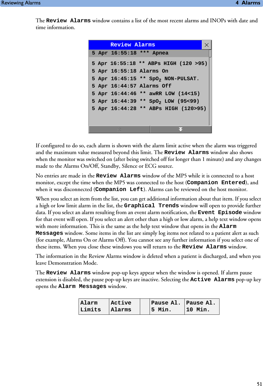

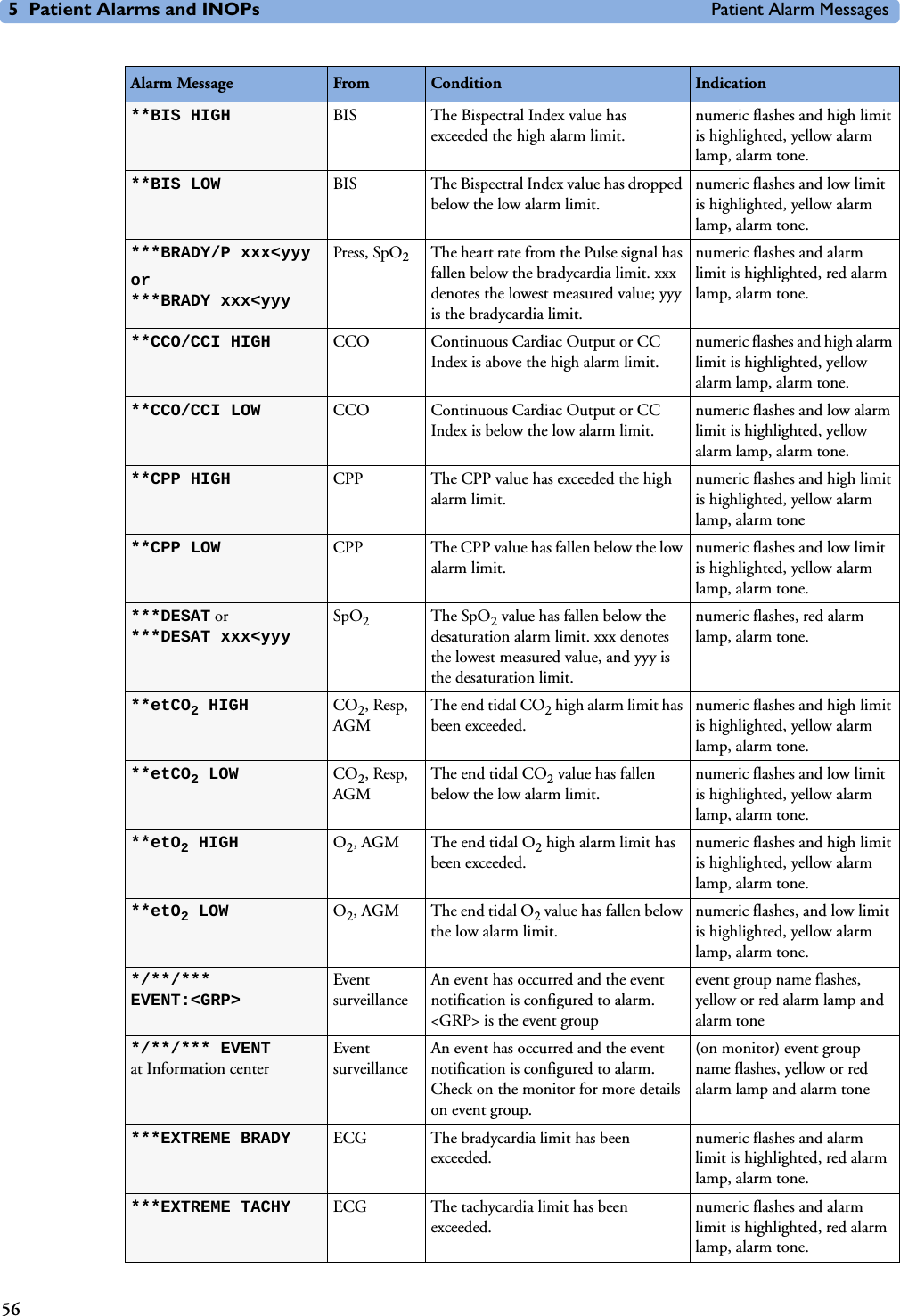
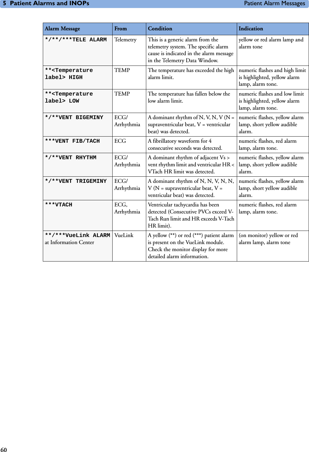
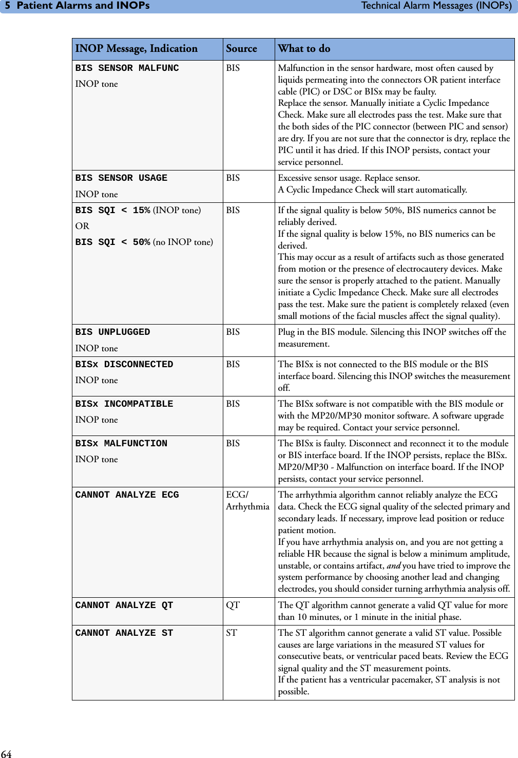
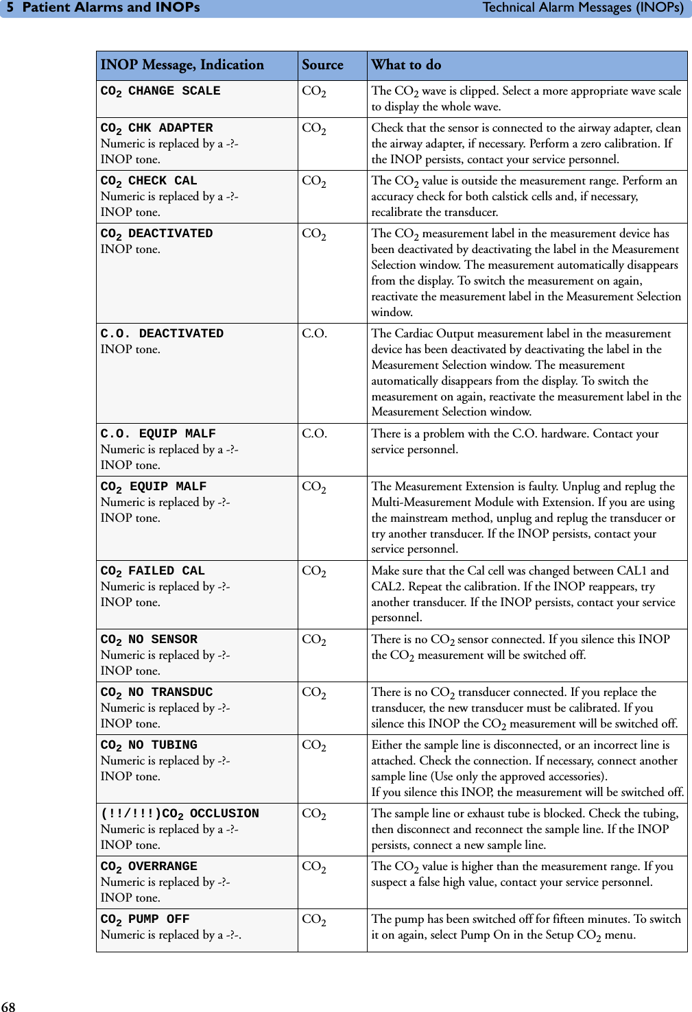
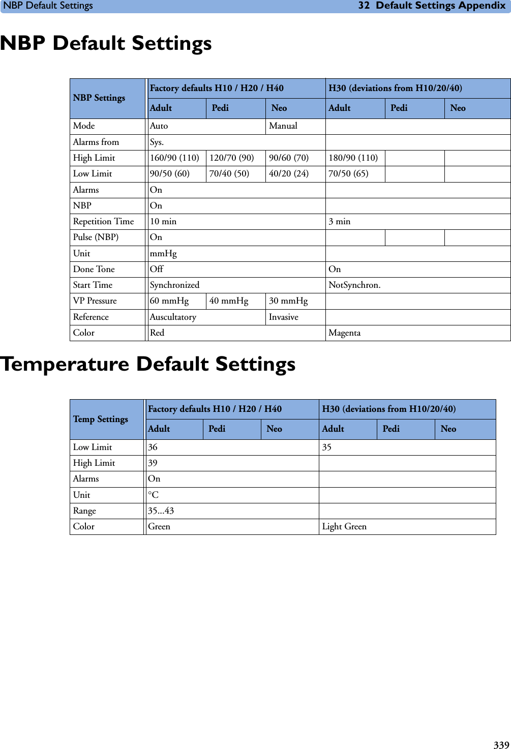
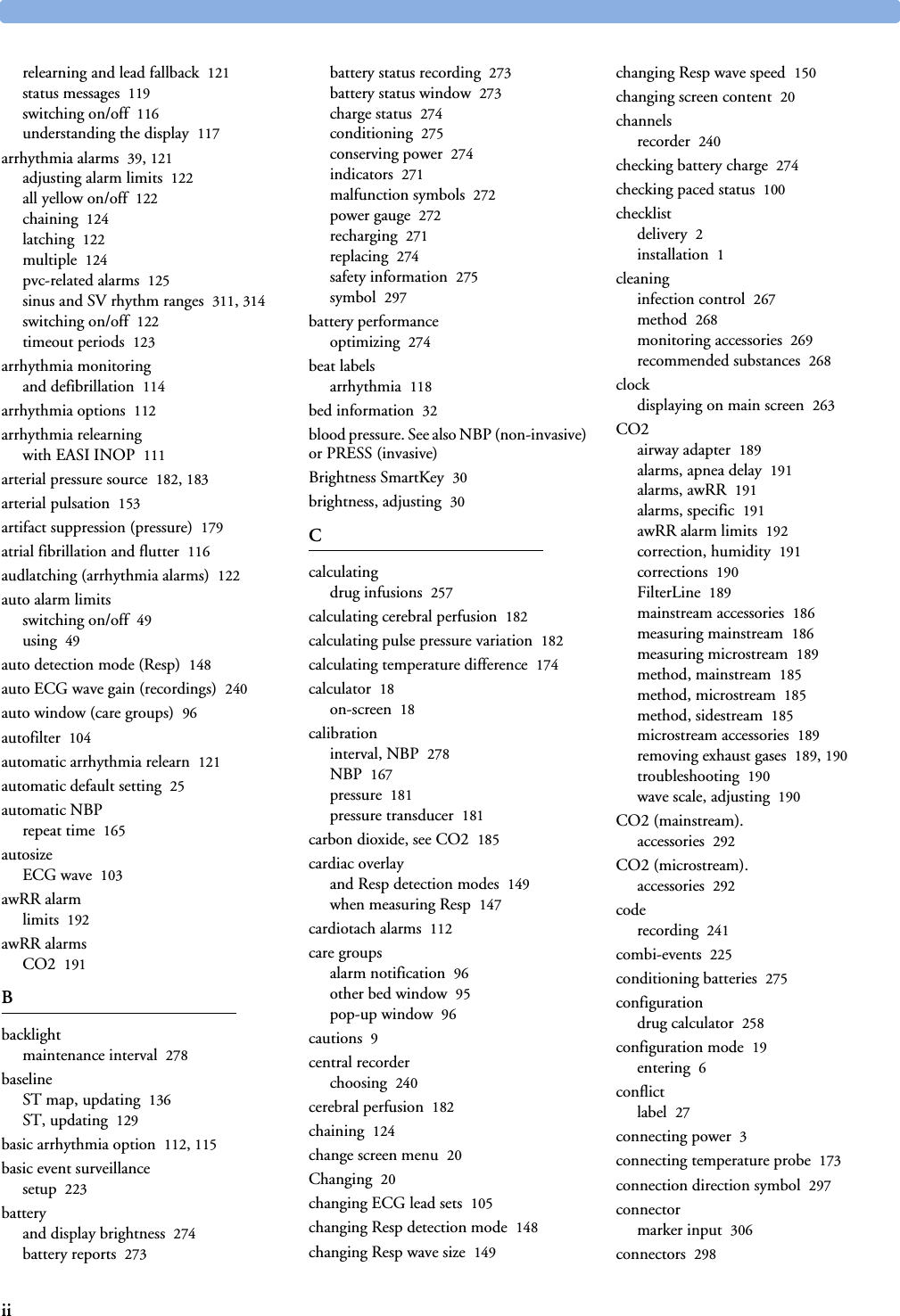
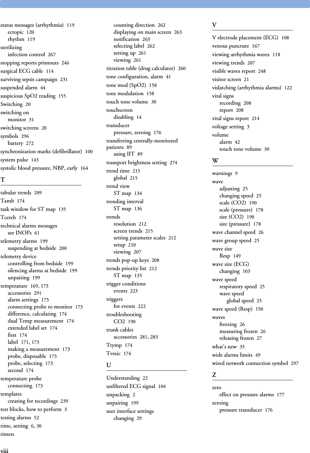
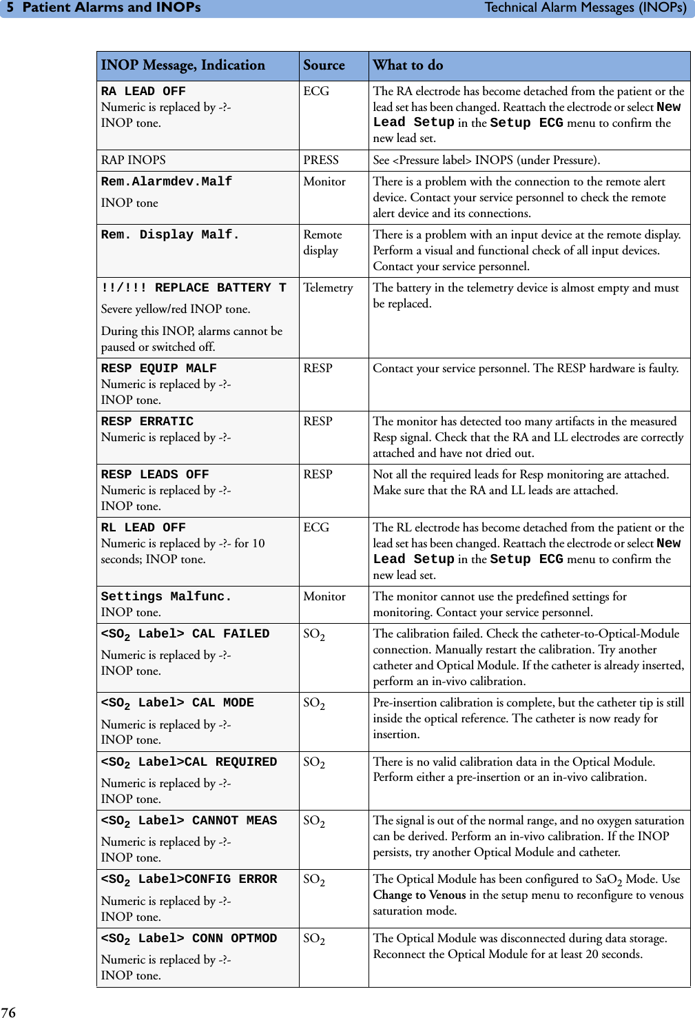
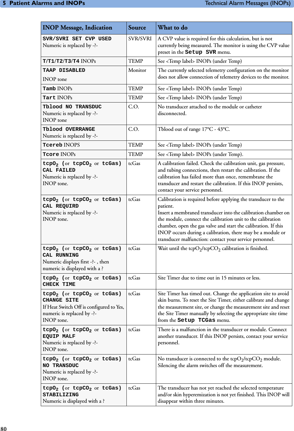
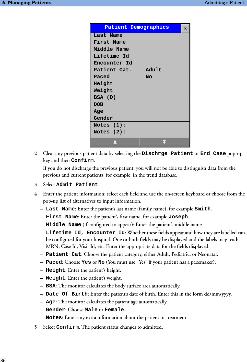
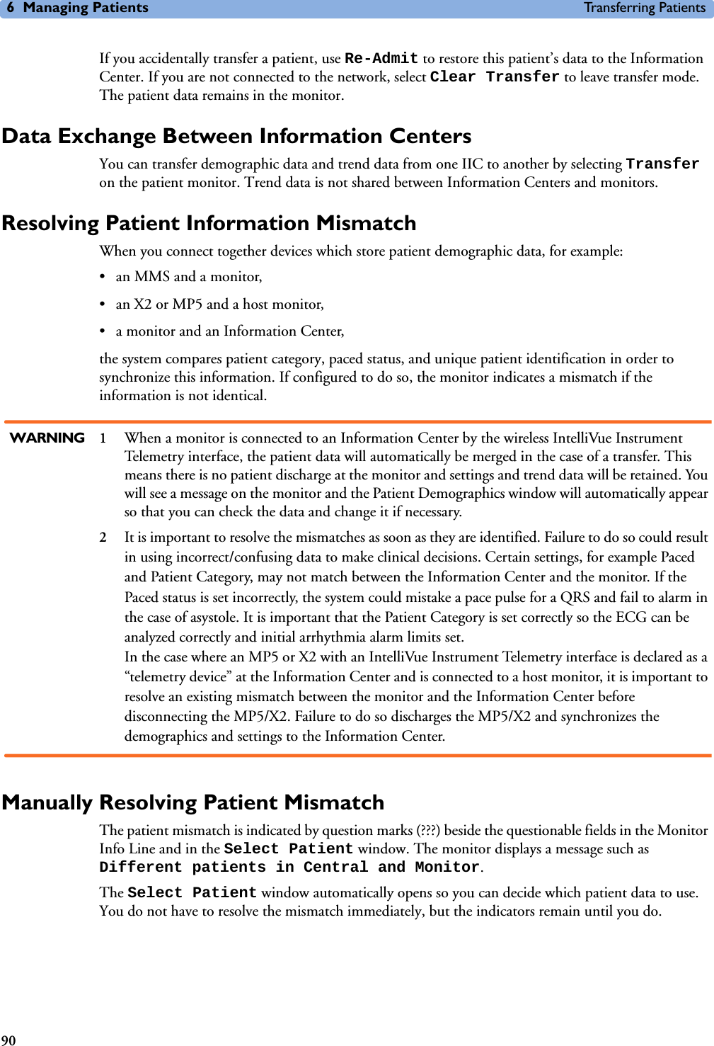
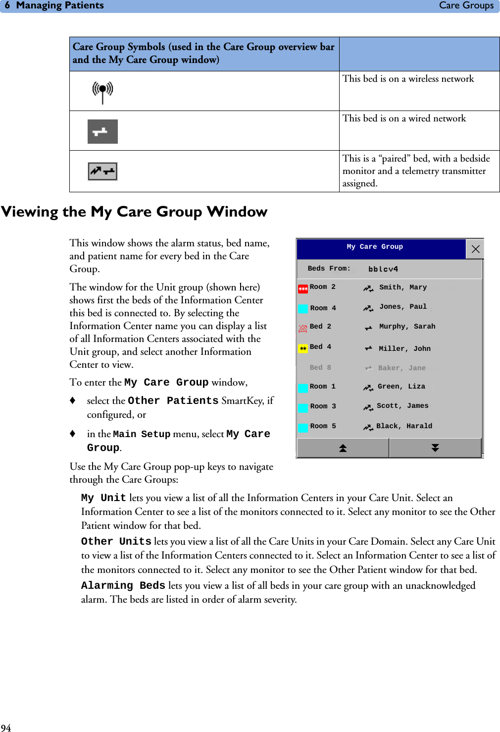
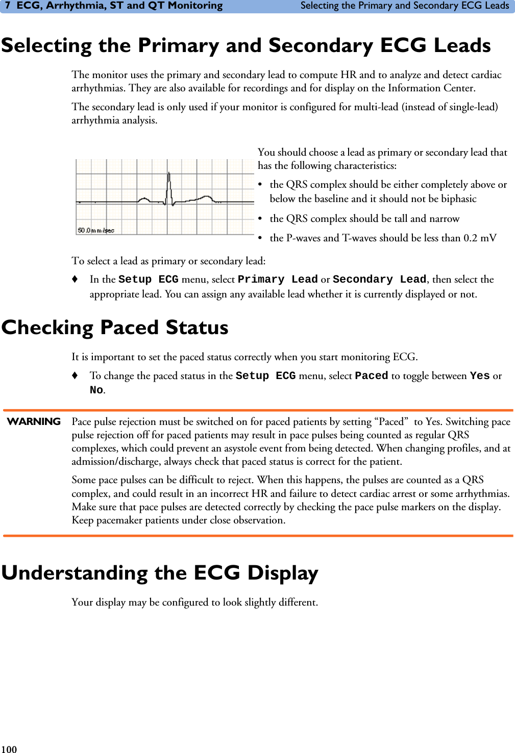
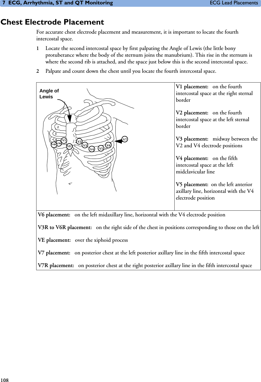
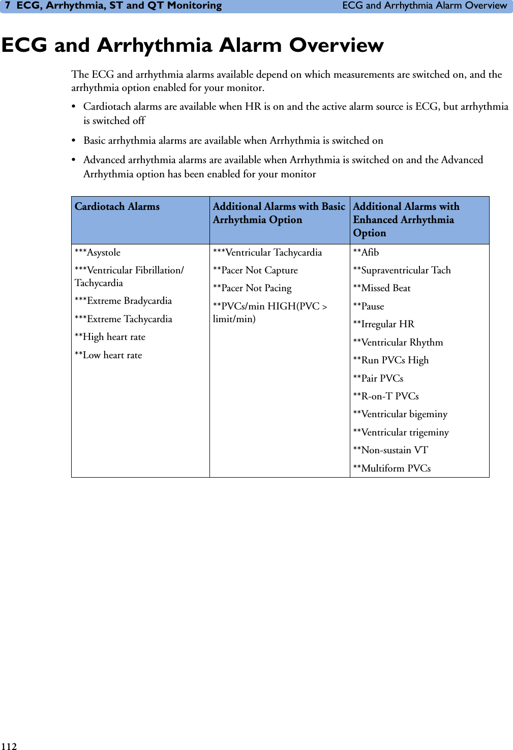
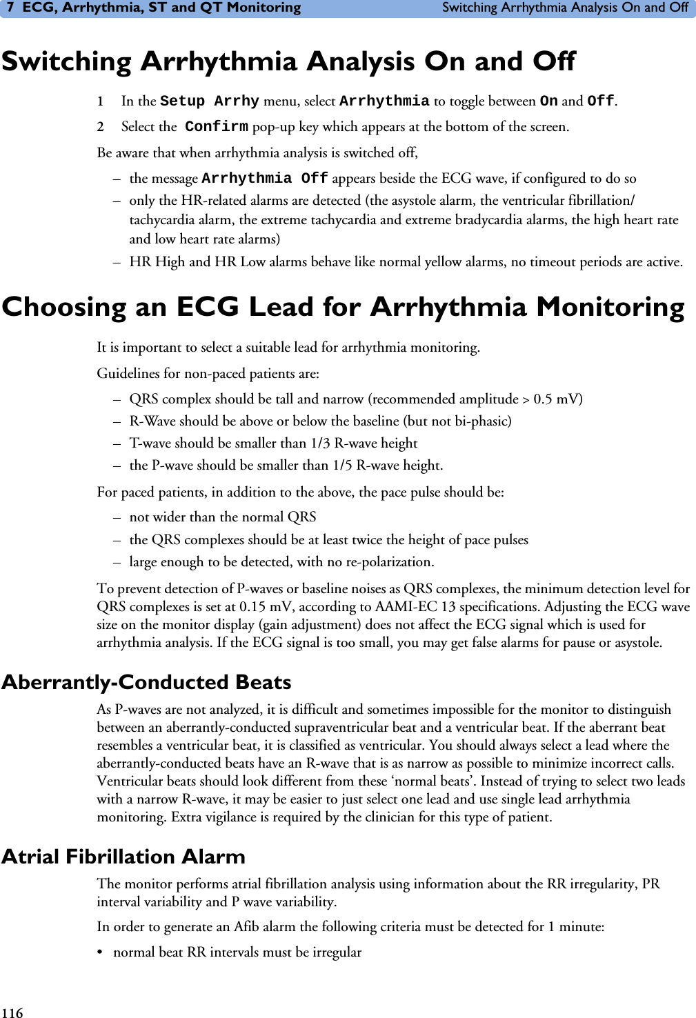
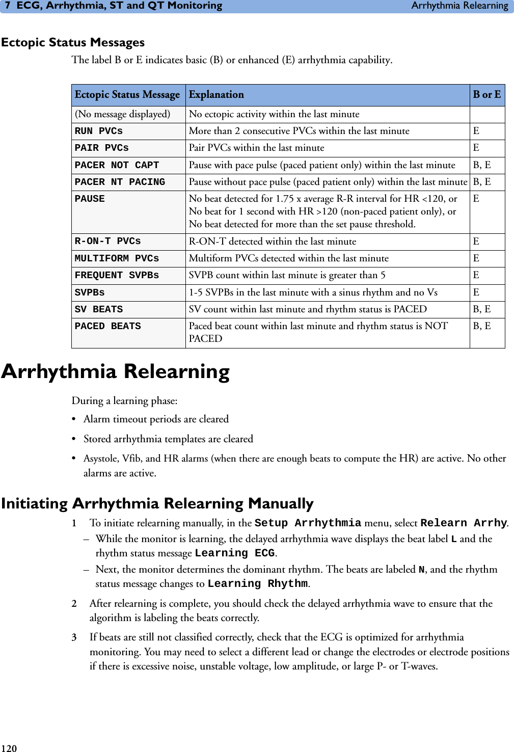
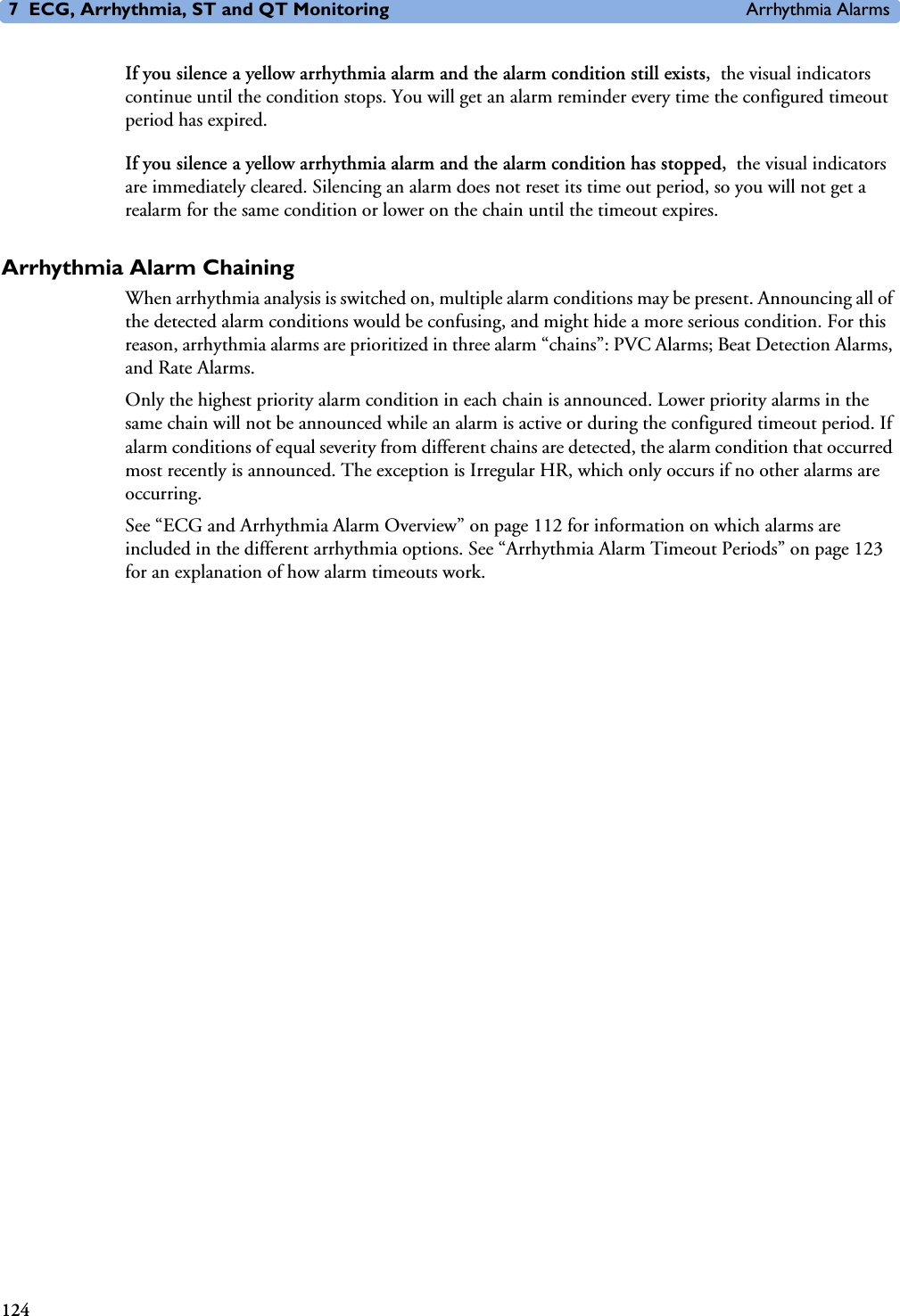
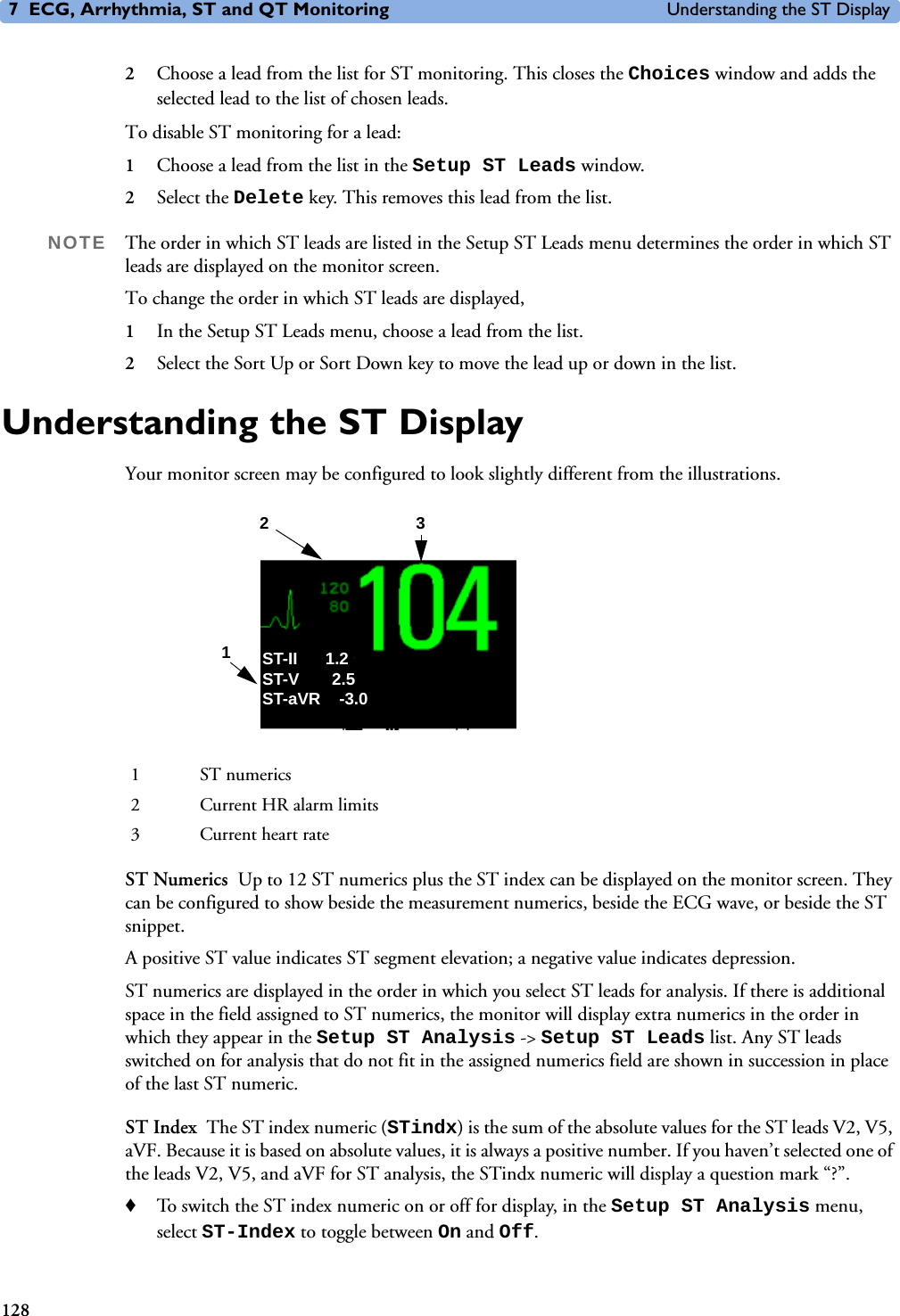
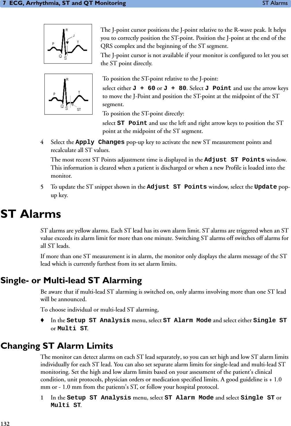
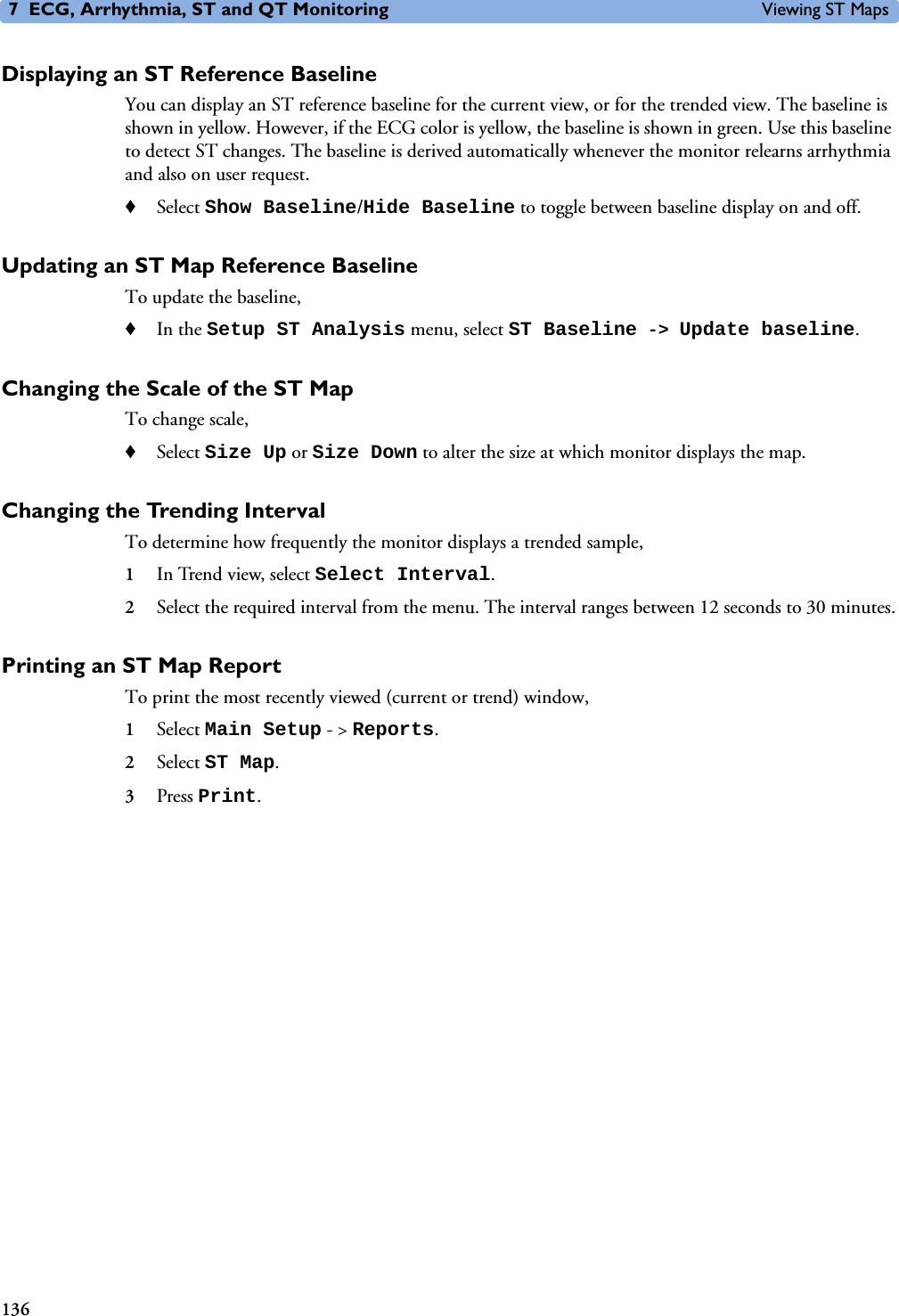
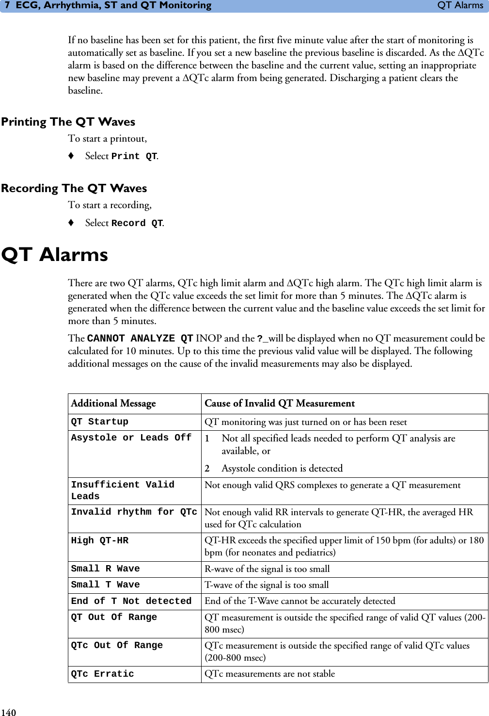
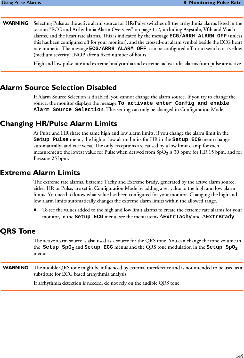
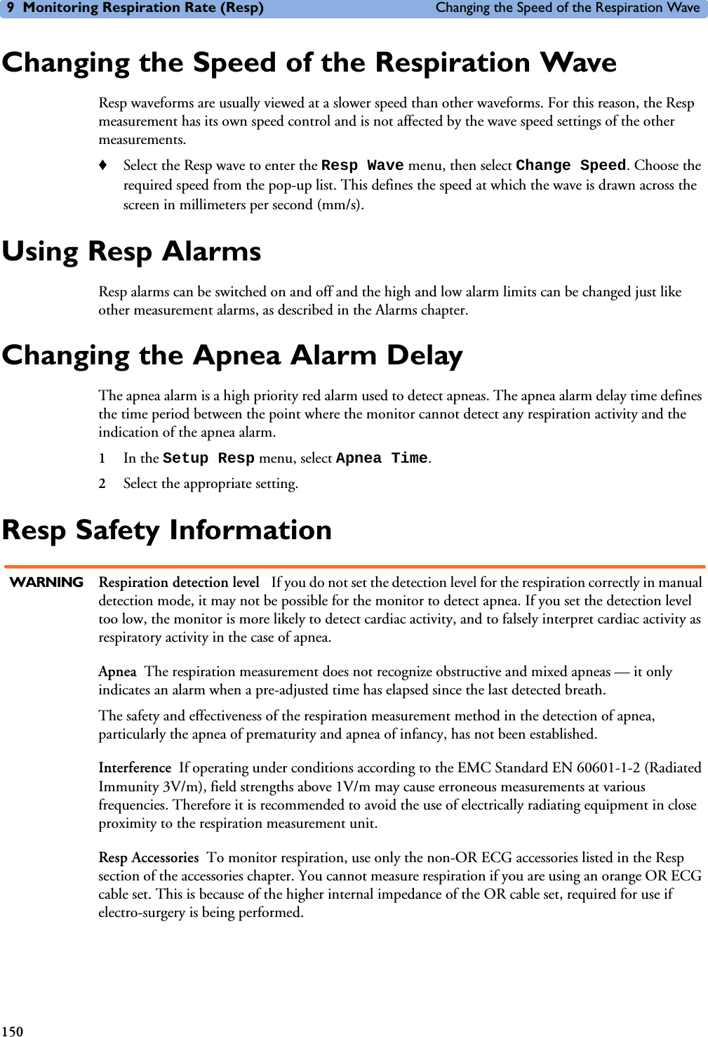
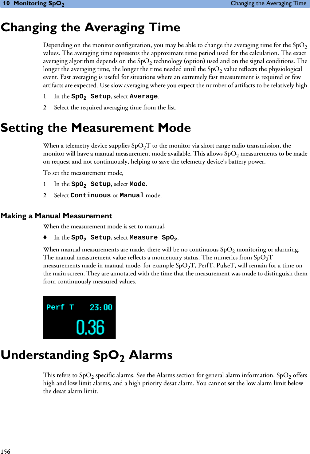
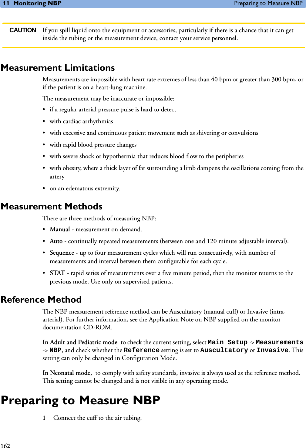
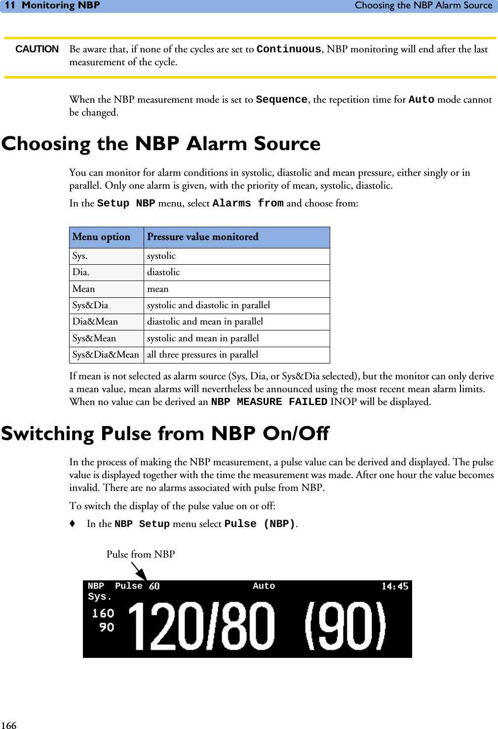
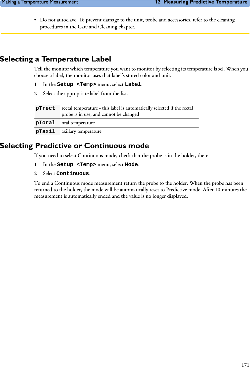
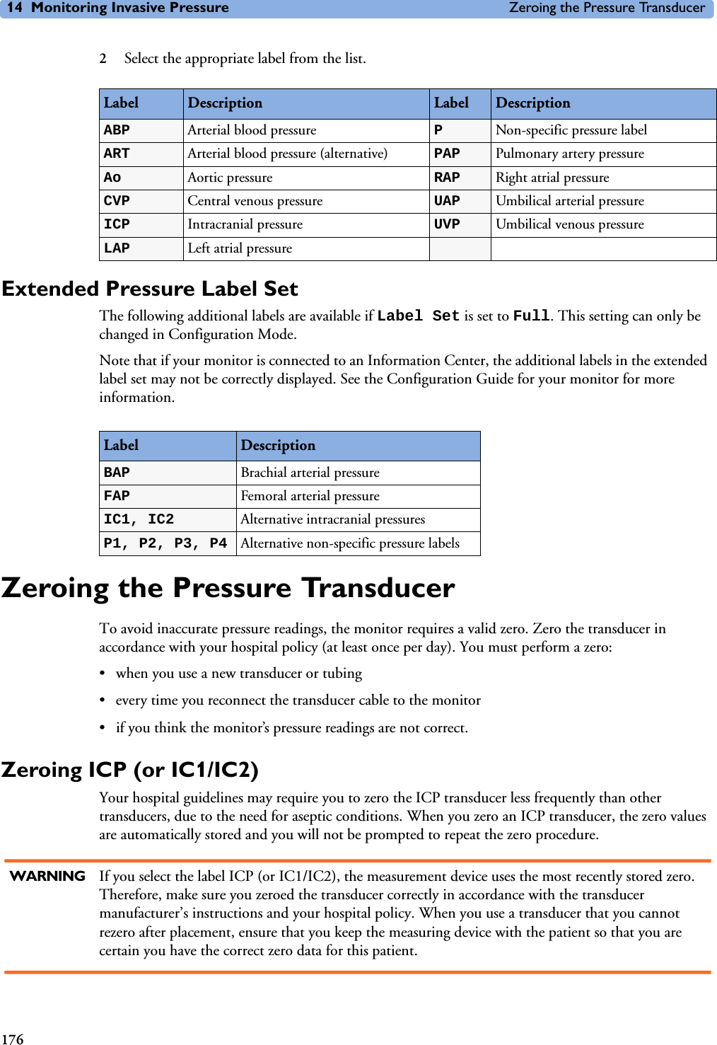
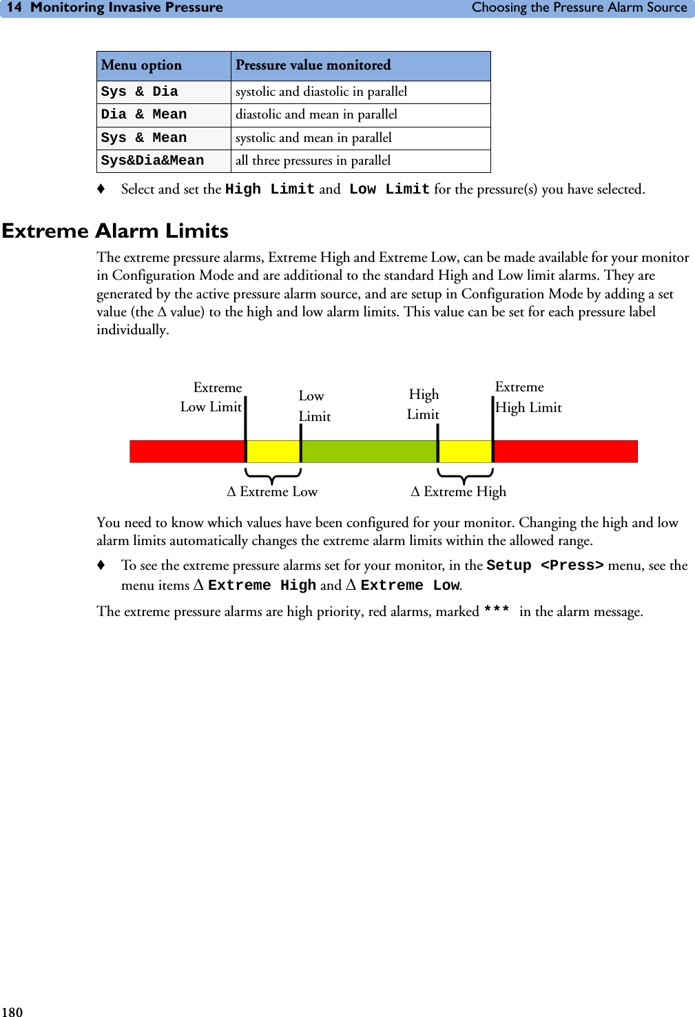
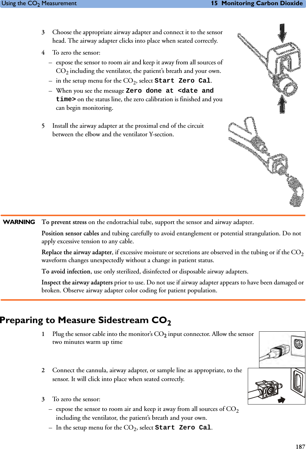
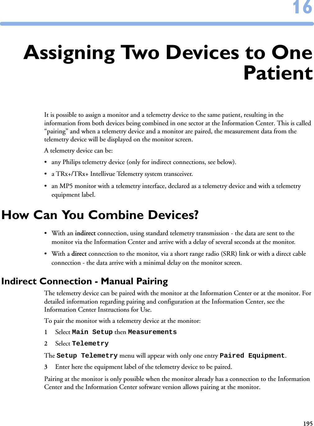
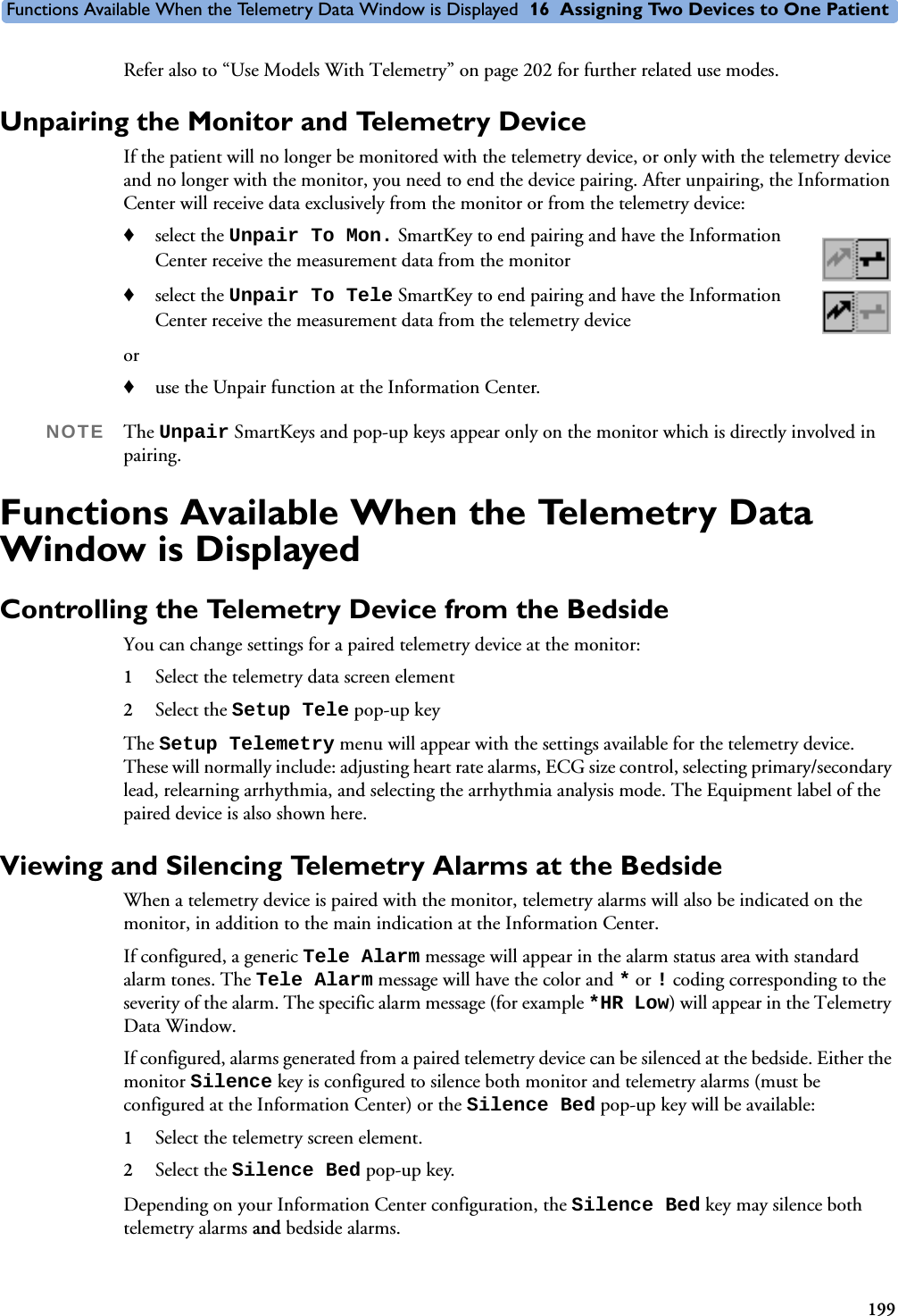
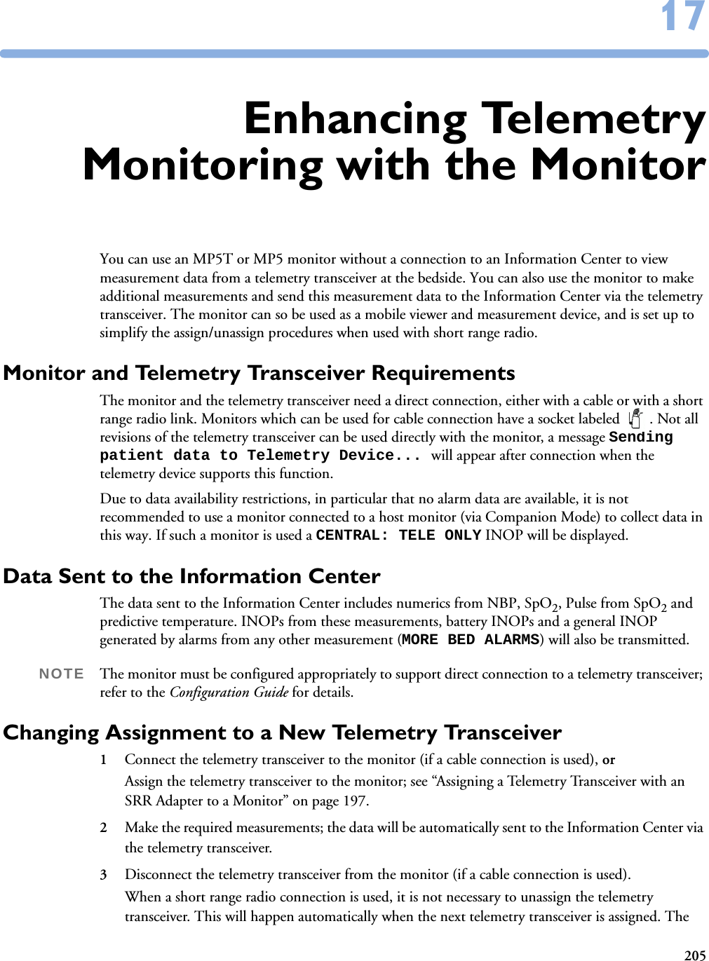
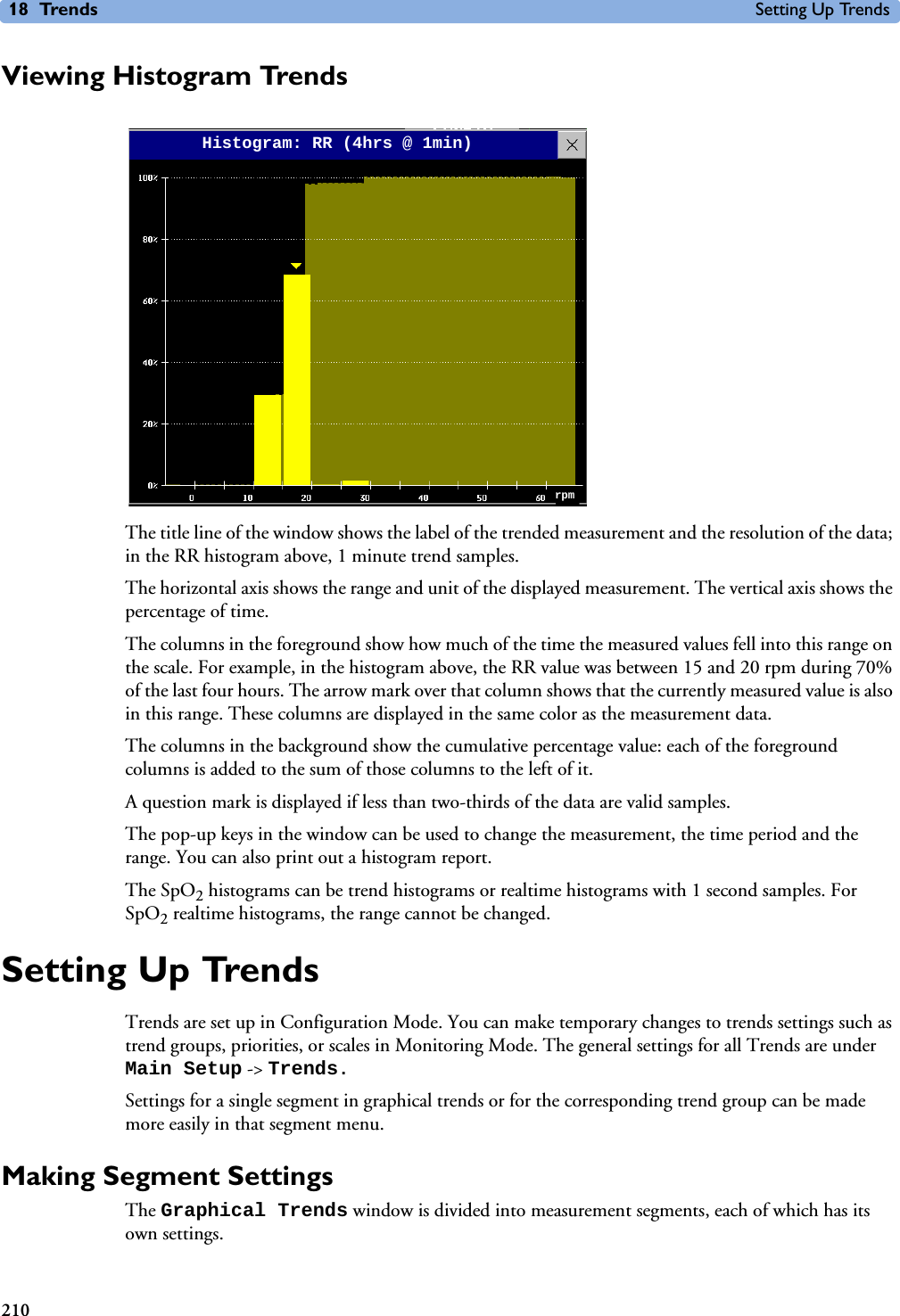
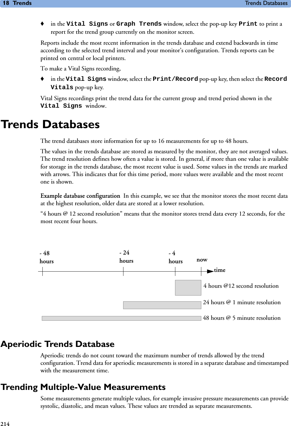
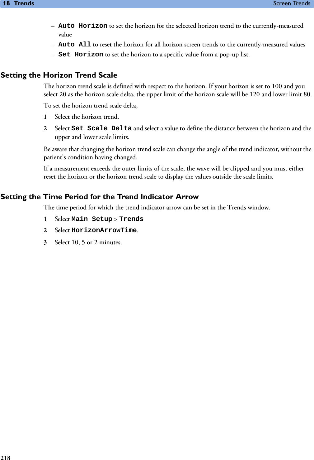
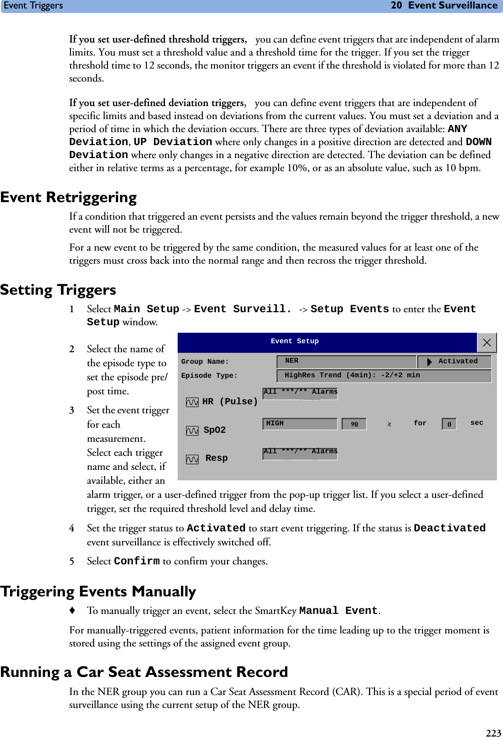
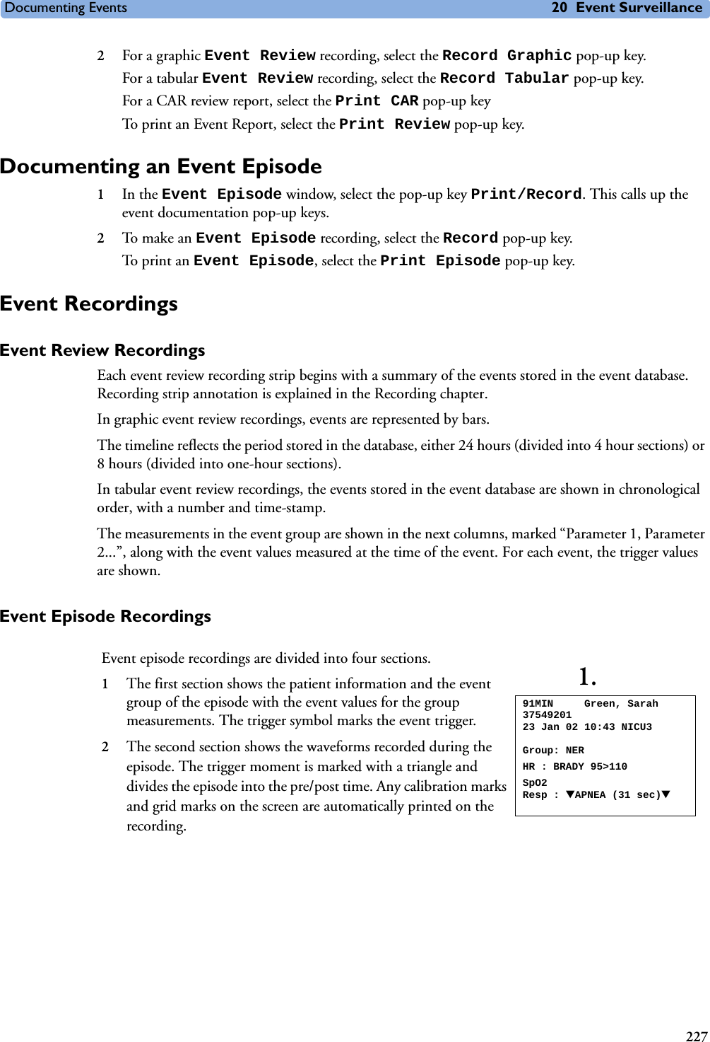
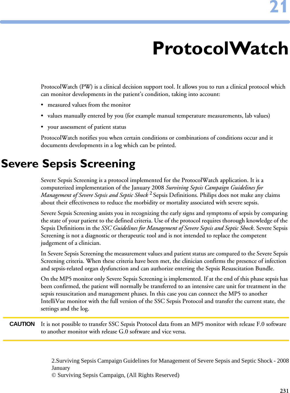
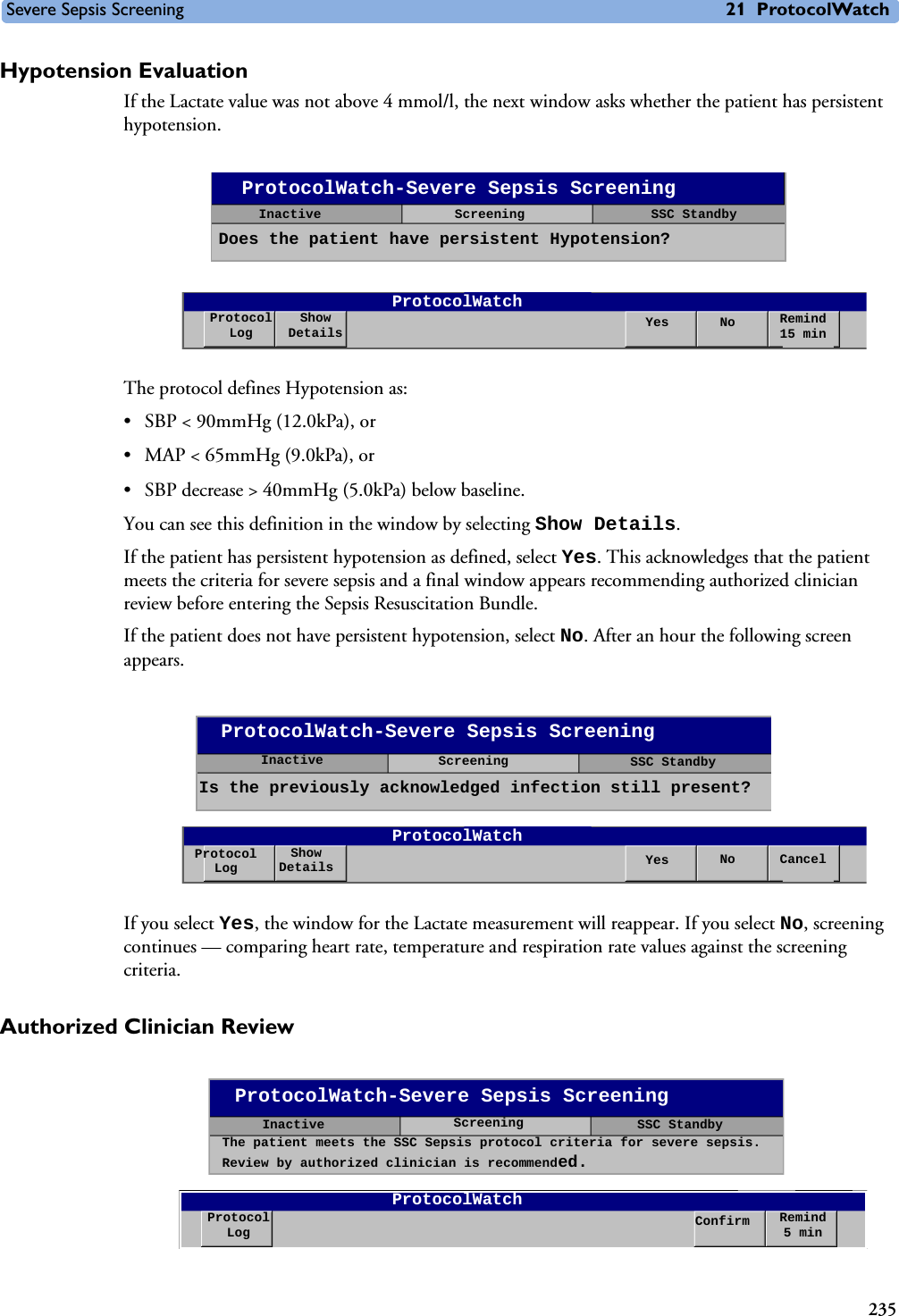
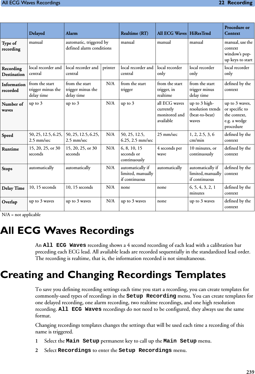
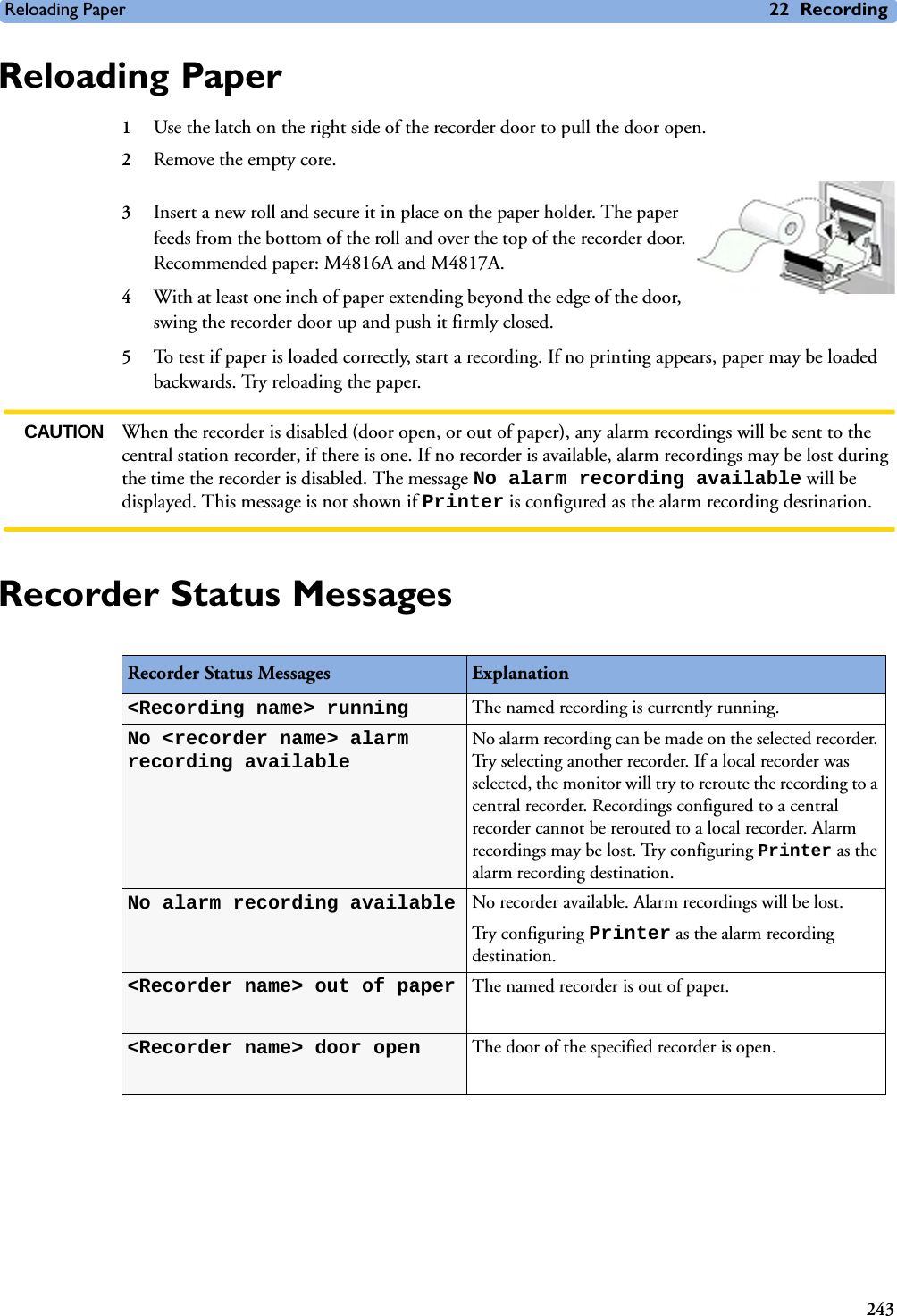
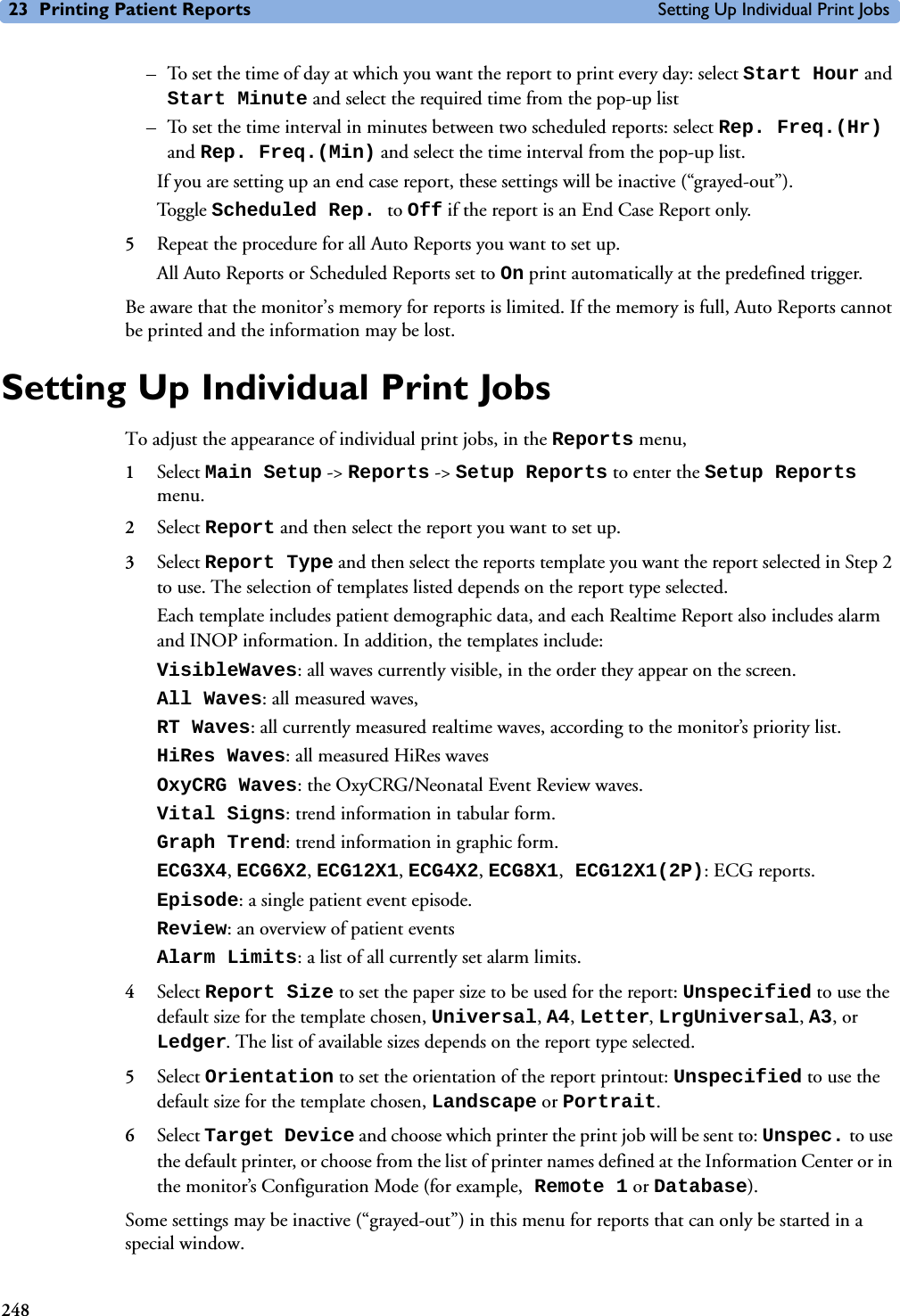
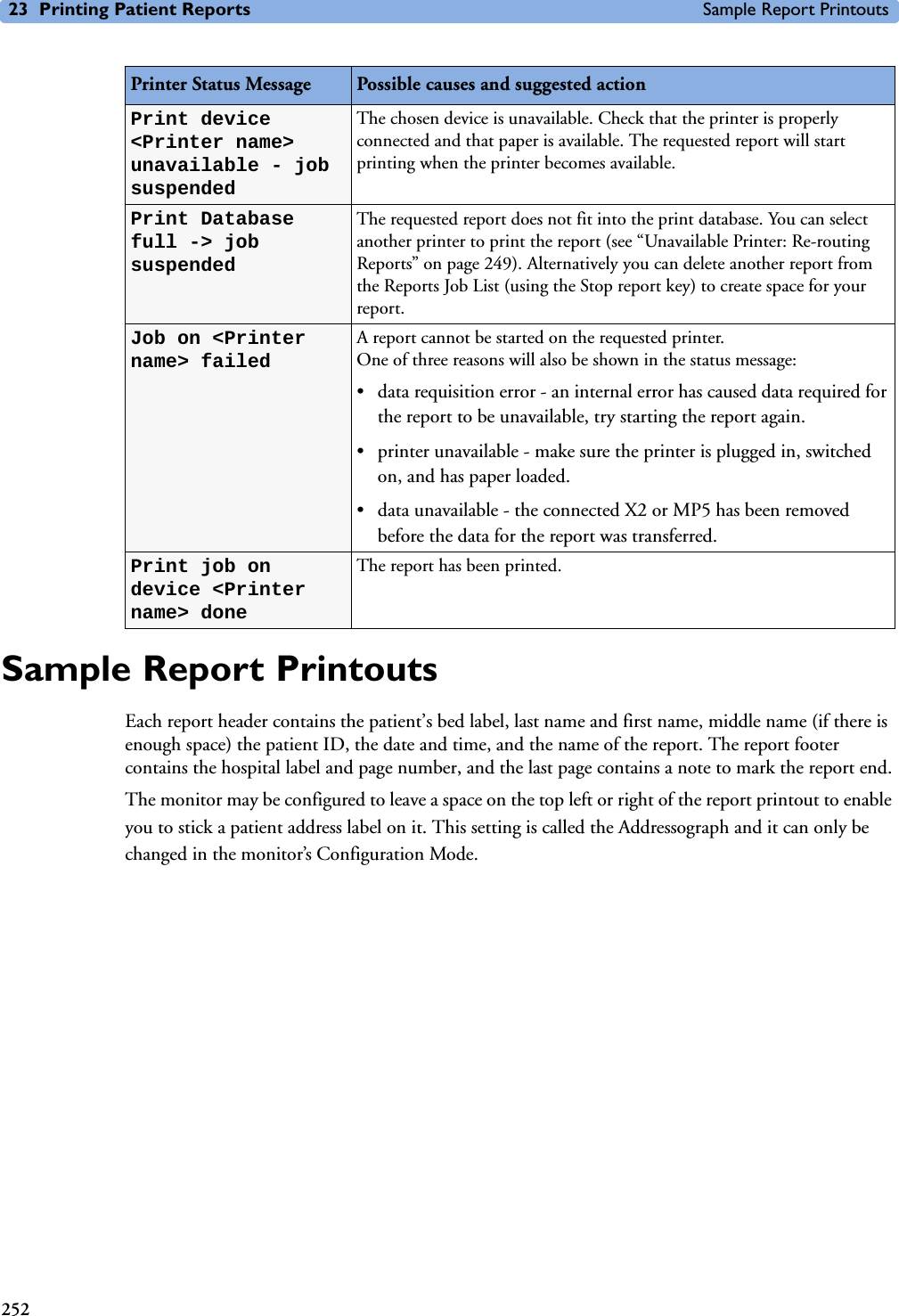
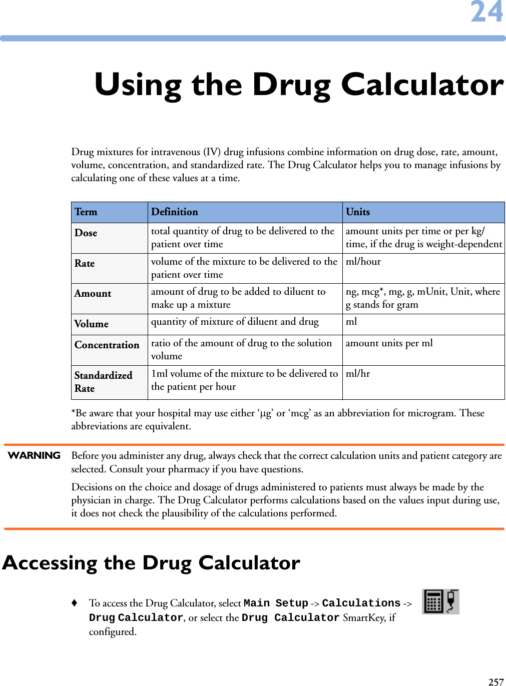
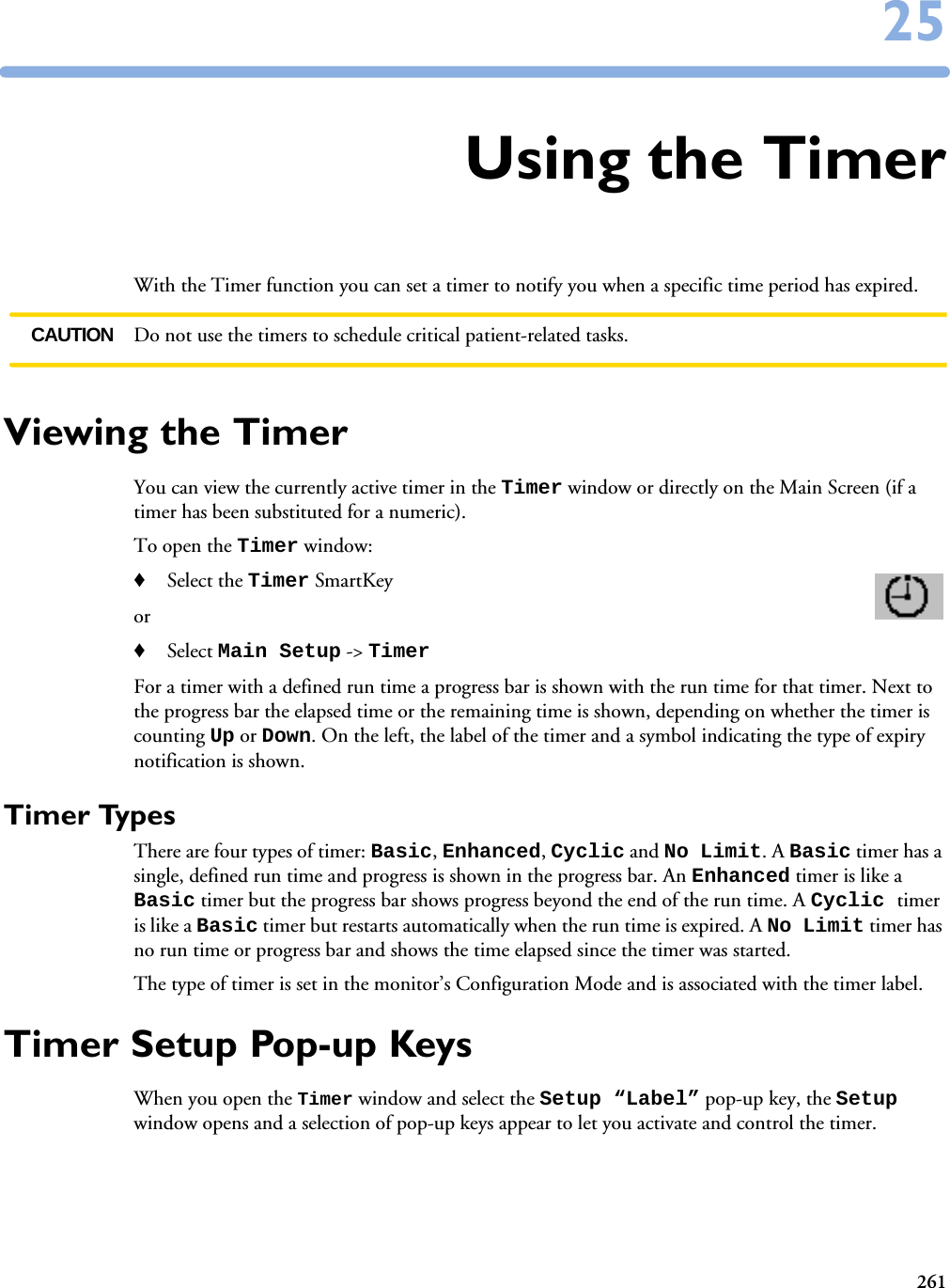
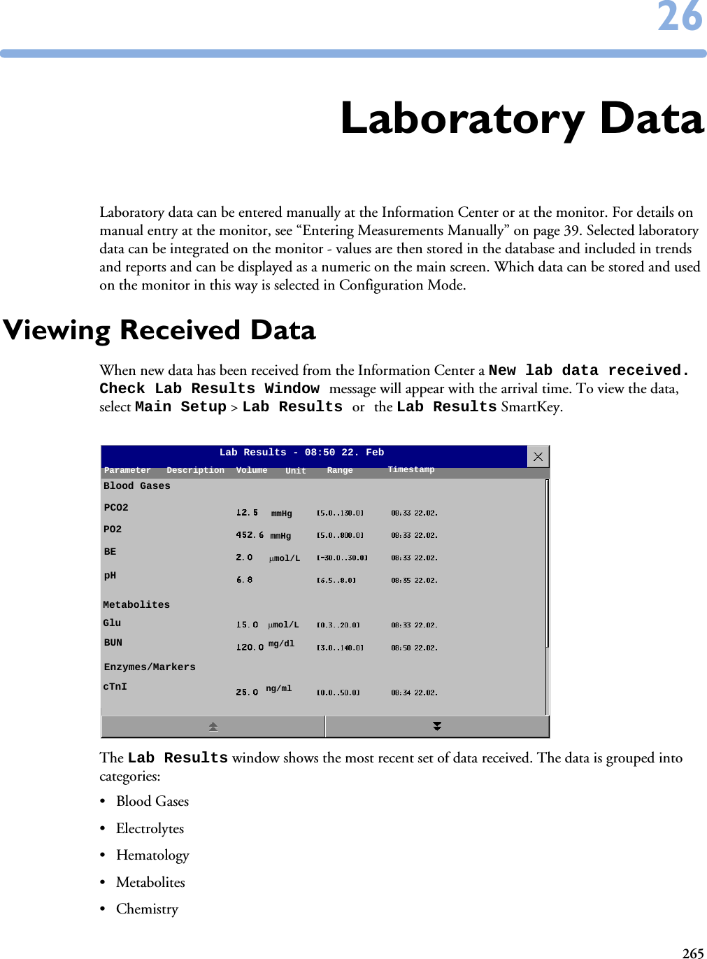
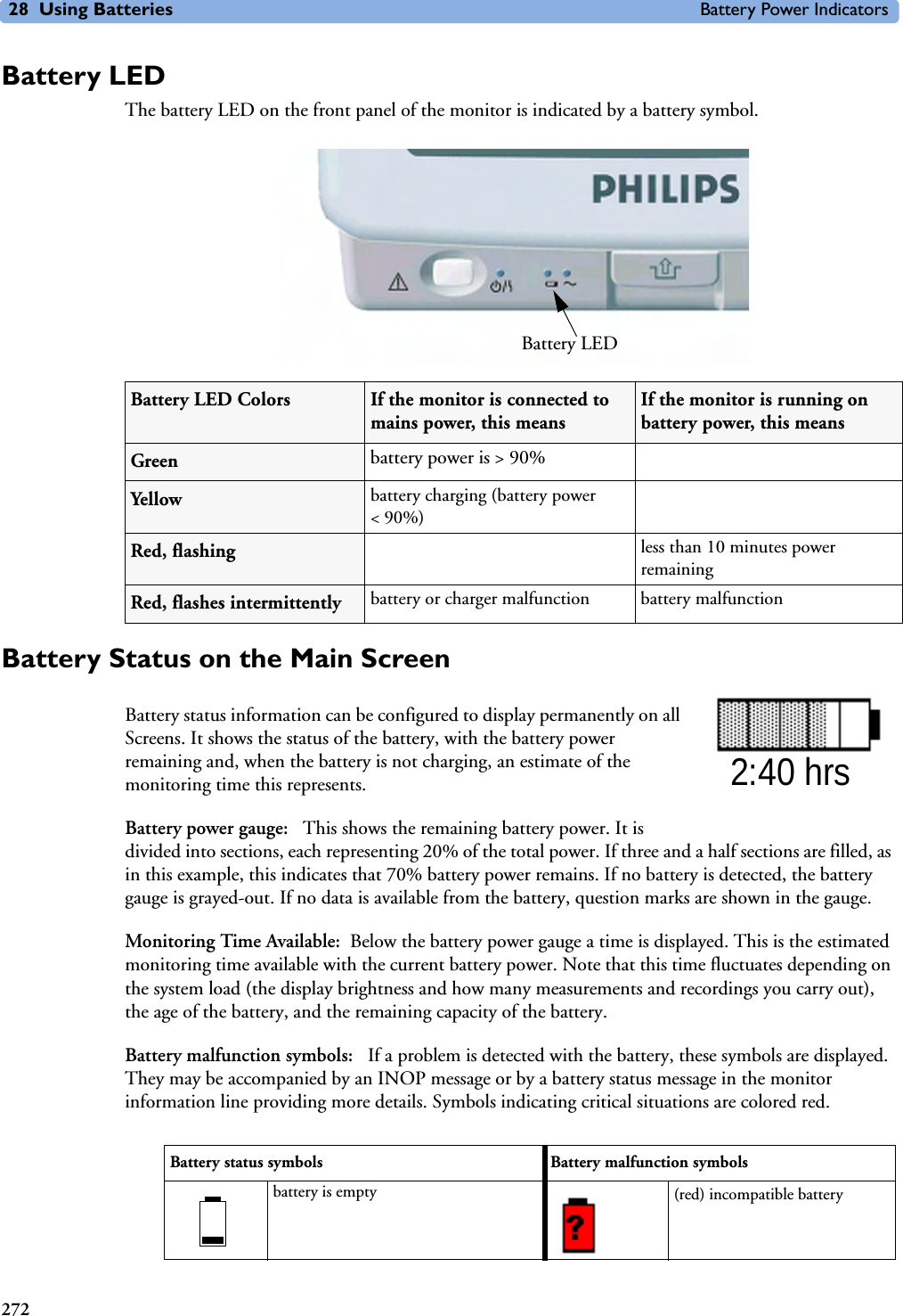
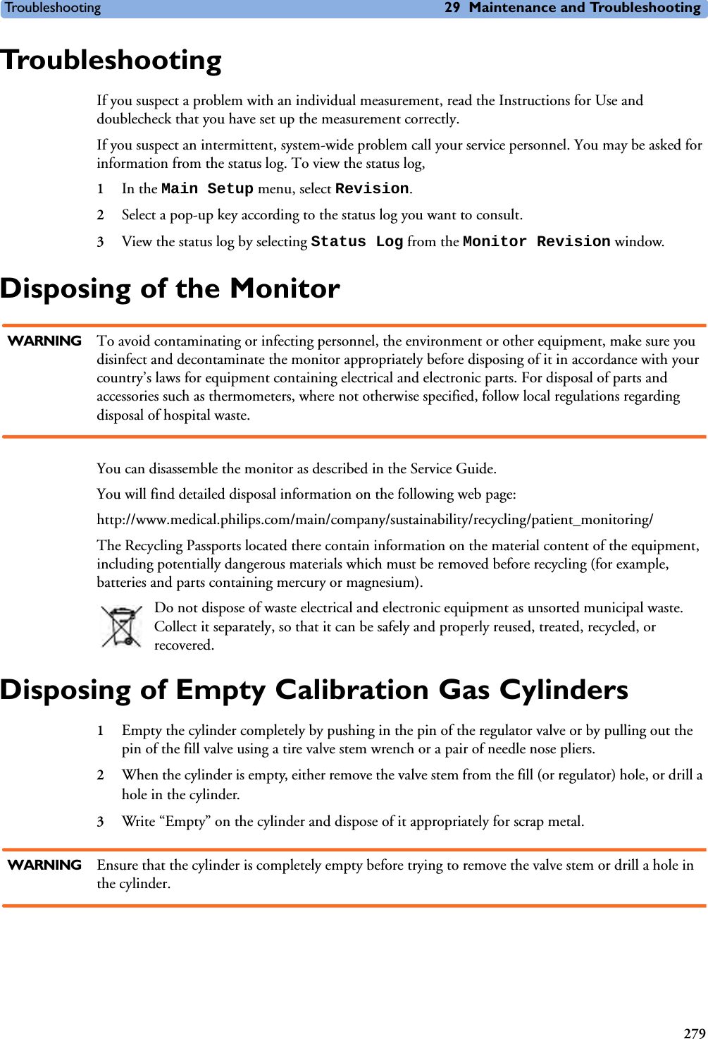
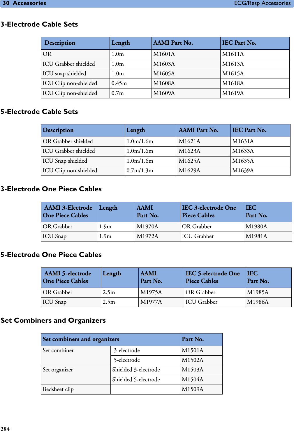
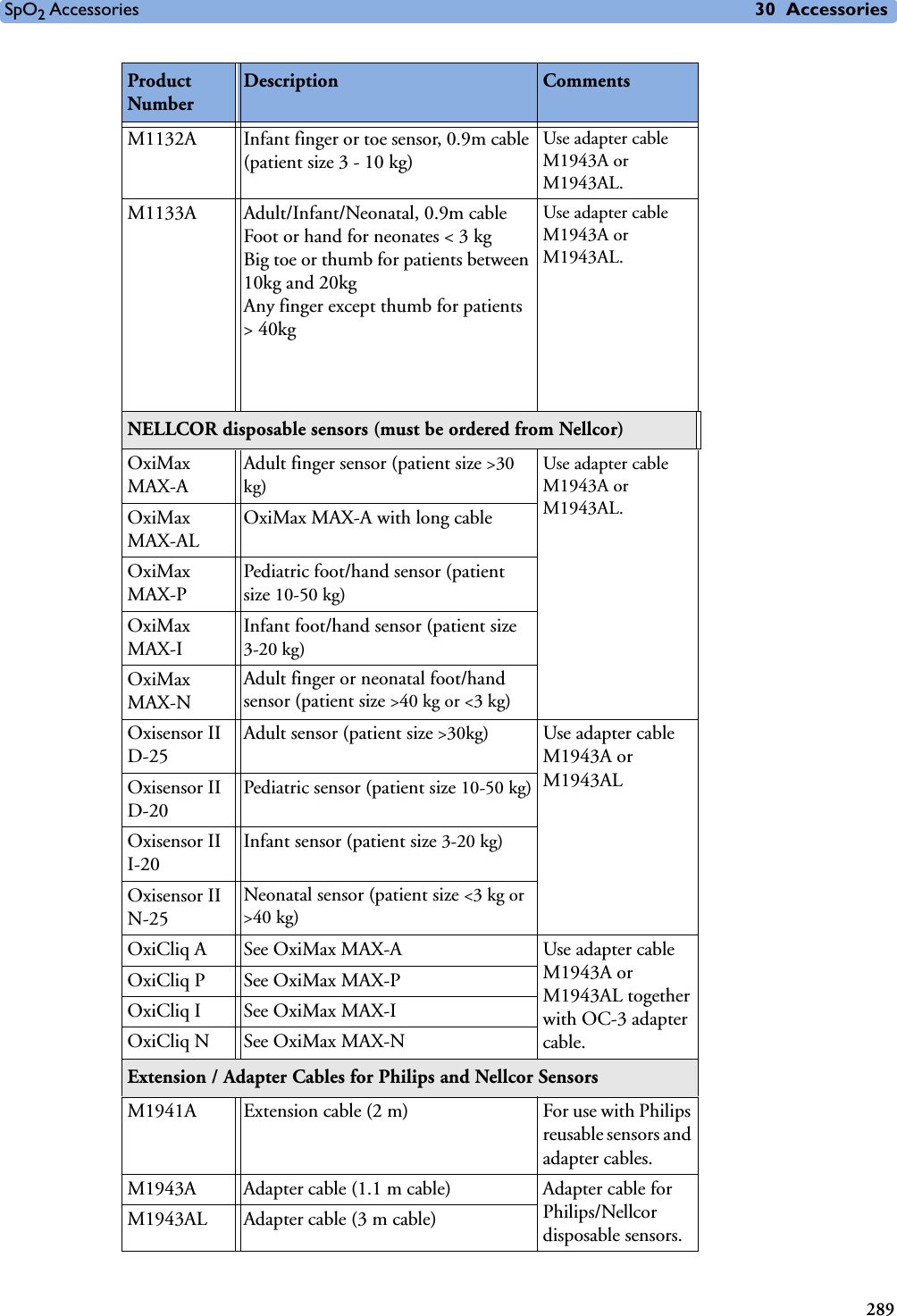
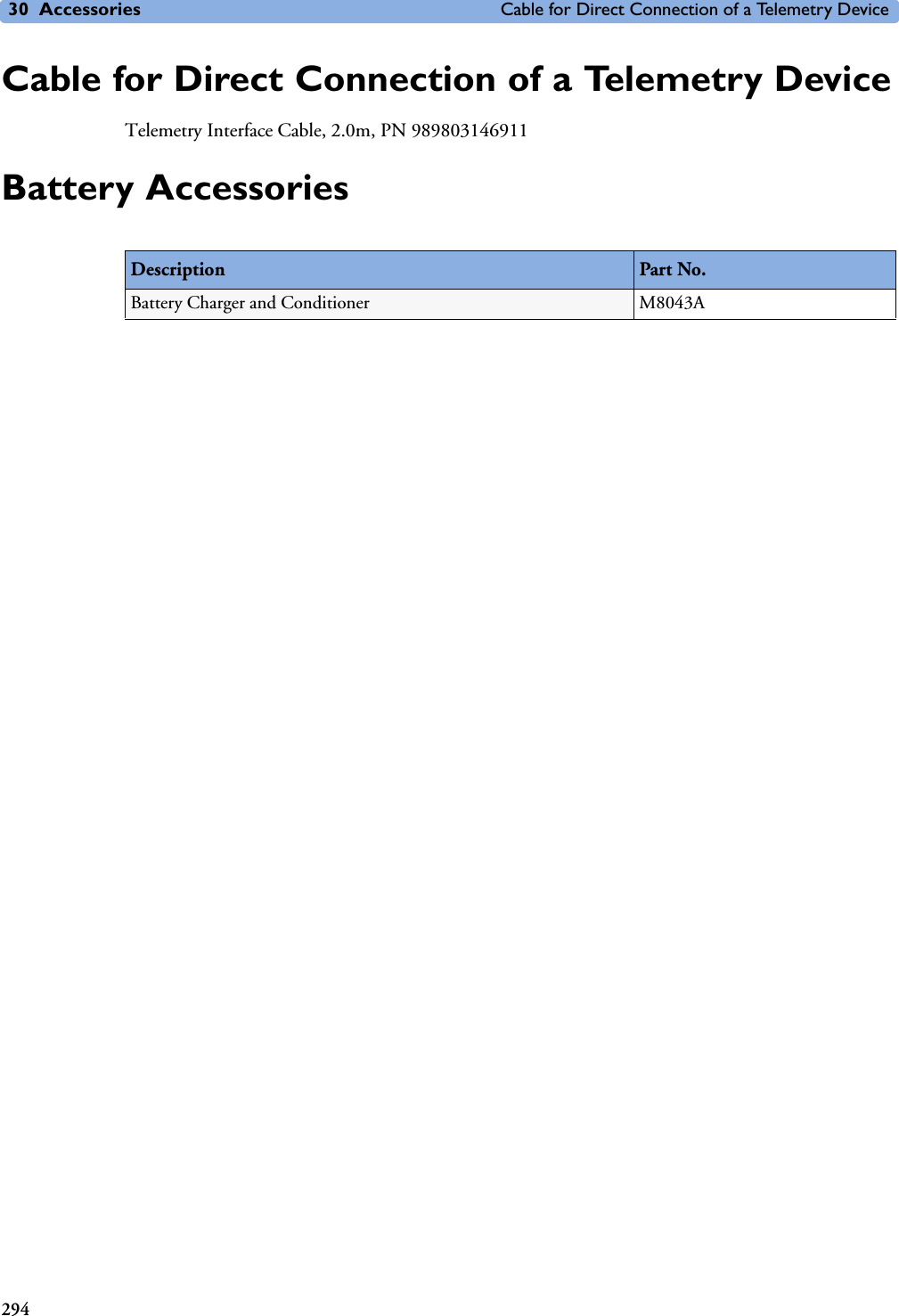
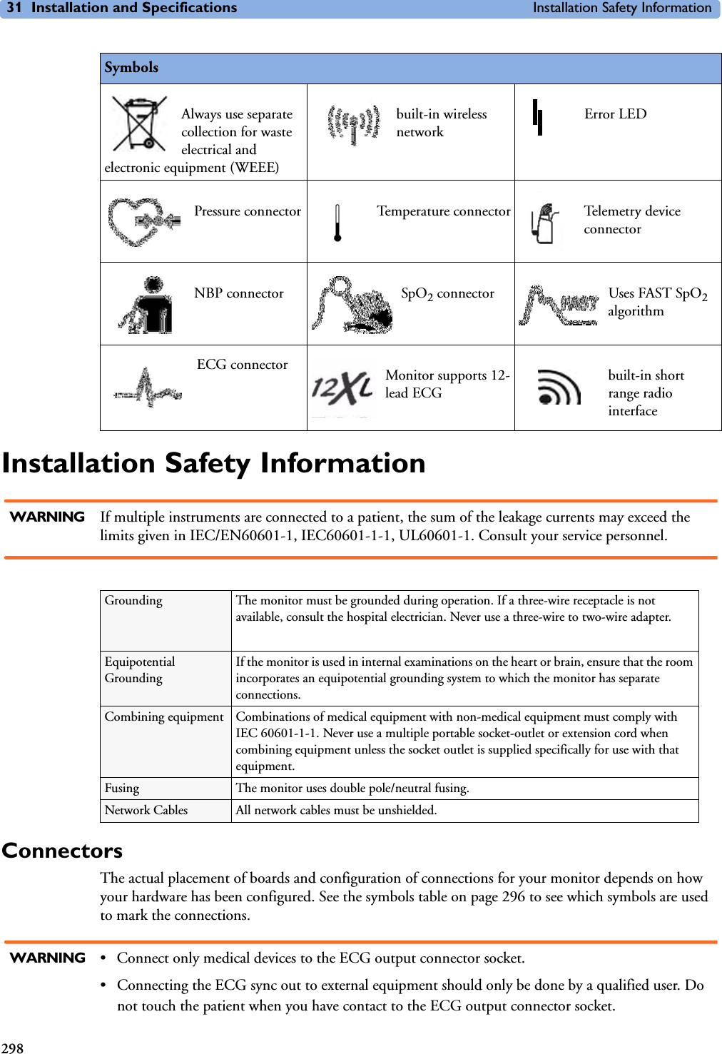
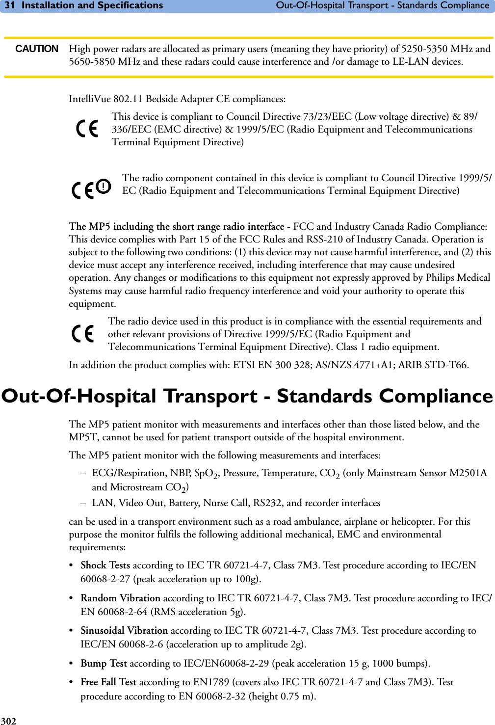
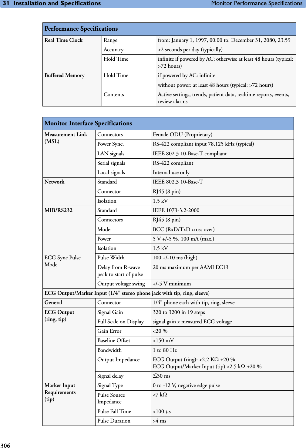
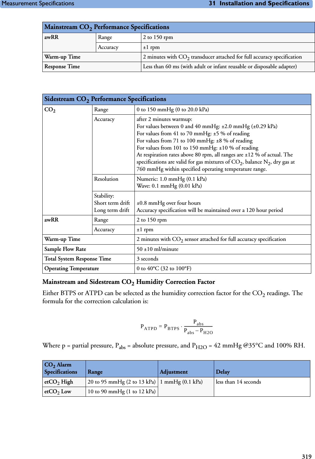
![Technical Alarm Messages (INOPs) 5 Patient Alarms and INOPs69CO2 PURGINGNumeric is replaced by a -?-INOP tone.CO2The Filterline is being purged to remove an occlusion in the line or airway adapter. If the occlusion is removed, the INOP will disappear. If not, the INOP CO2 OCCLUSION is displayed.CO2 SENS. WARMUPNumeric is displayed with a -?-Microstream CO2: INOP tone. Mainstream CO2: no INOP toneCO2Wait until the sensor reaches operating temperature and the INOP disappears.C.O. UNPLUGGEDnumeric is replaced by -?-INOP tone.C.O. Plug in the C.O. module. Silencing this INOP switches off the measurement.CO2 UPDATE FWNumeric is replaced by a -?-INOP tone.CO2The software in the Measurement Extension does not match the software in the MMS. Contact your service personnel.CO2 WAIT CAL2Numeric is replaced by a -?- CO2Calibration on the first calstick cell is complete. Place the transducer on the other calstick cell and start the CAL2 calibration cycle. CO2 ZERO FAILEDNumeric is replaced by a -?- INOP tone.CO2An error occurred during the last zero calibration. Check the airway adapter and clean, if necessary. Perform another zero calibration. If the INOP persists, contact your service personnel.CO2 ZERO REQU’DNumeric is replaced by a -?- INOP toneCO2Perform zero calibration for the CO2 sensor. If the INOP persists, contact your service personnel.CO2 ZERO RUNNING CO2Wait until zero calibration is finished.CPP CHK SOURCESNumeric is replaced by a -?- CPP Not all measurements or values required to perform the calculation are available. Check the measurement sources.CPP CHK UNITSNumeric is replaced by a -?- CPP The monitor has detected a conflict in the units used for this calculation. Check the unit settings.!!/!!!CUFF NOT DEFLATNumeric is displayed with a -?-Severe yellow/red INOP tone. During this INOP, alarms cannot be paused or switched off. NBP Remove the cuff from the patient. Make sure that the tubing is not kinked or twisted and that the correct patient category is selected. Try repeating the measurement. You can silence the INOP, but the INOP message remains visible until the next NBP measurement is started or the Stop All SmartKey is selected.[Adult or pediatric patients: The NBP cuff pressure has exceeded 15mmHg (2kPa) for more than 3 minutes. Neonatal patients: The NBP cuff pressure has exceeded 5mmHg (0.7kPa) for more than 90 seconds.]!!/!!!CUFF OVERPRESSNumeric displayed with -?- ; Severe yellow/red INOP tone.During this INOP, alarms cannot be paused or switched off.NBP The NBP cuff pressure exceeds the overpressure safety limits. Remove the cuff from the patient. Make sure that the tubing is not kinked or twisted and that the correct patient category is selected. Try restarting the measurement. You can silence this INOP, but the INOP message remains visible until the next measurement is started or the Stop All SmartKey is selected.CVP INOPS PRESS See <Pressure label> INOPS (under Pressure).DEVICE CHECK SETUPINOP tone. IntelliBridge Device identification completed, but communication could not be established due to timeout.IntelliBridge INOP abbreviations may differ slightly depending on the device category.INOP Message, Indication Source What to do](https://usermanual.wiki/Philips-Medical-Systems-North-America/SRRBV1.User-Manual-MP5-and-MP5T/User-Guide-1044633-Page-79.png)
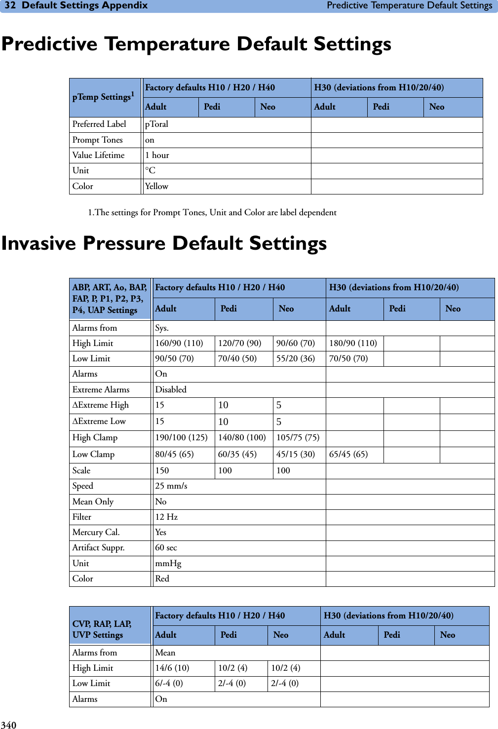
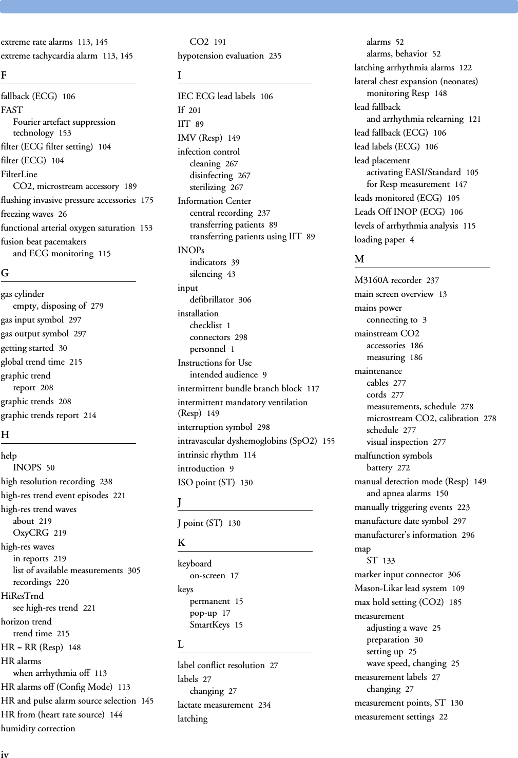
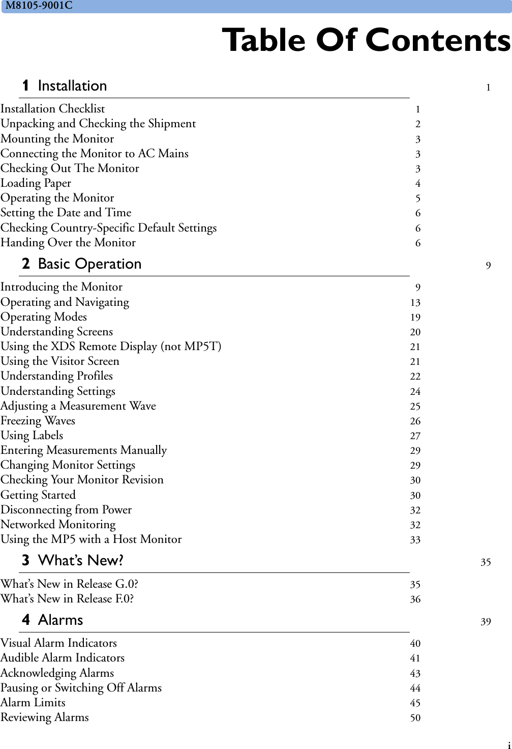
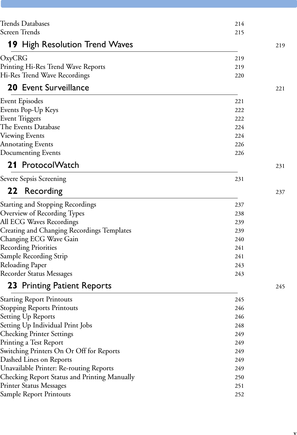
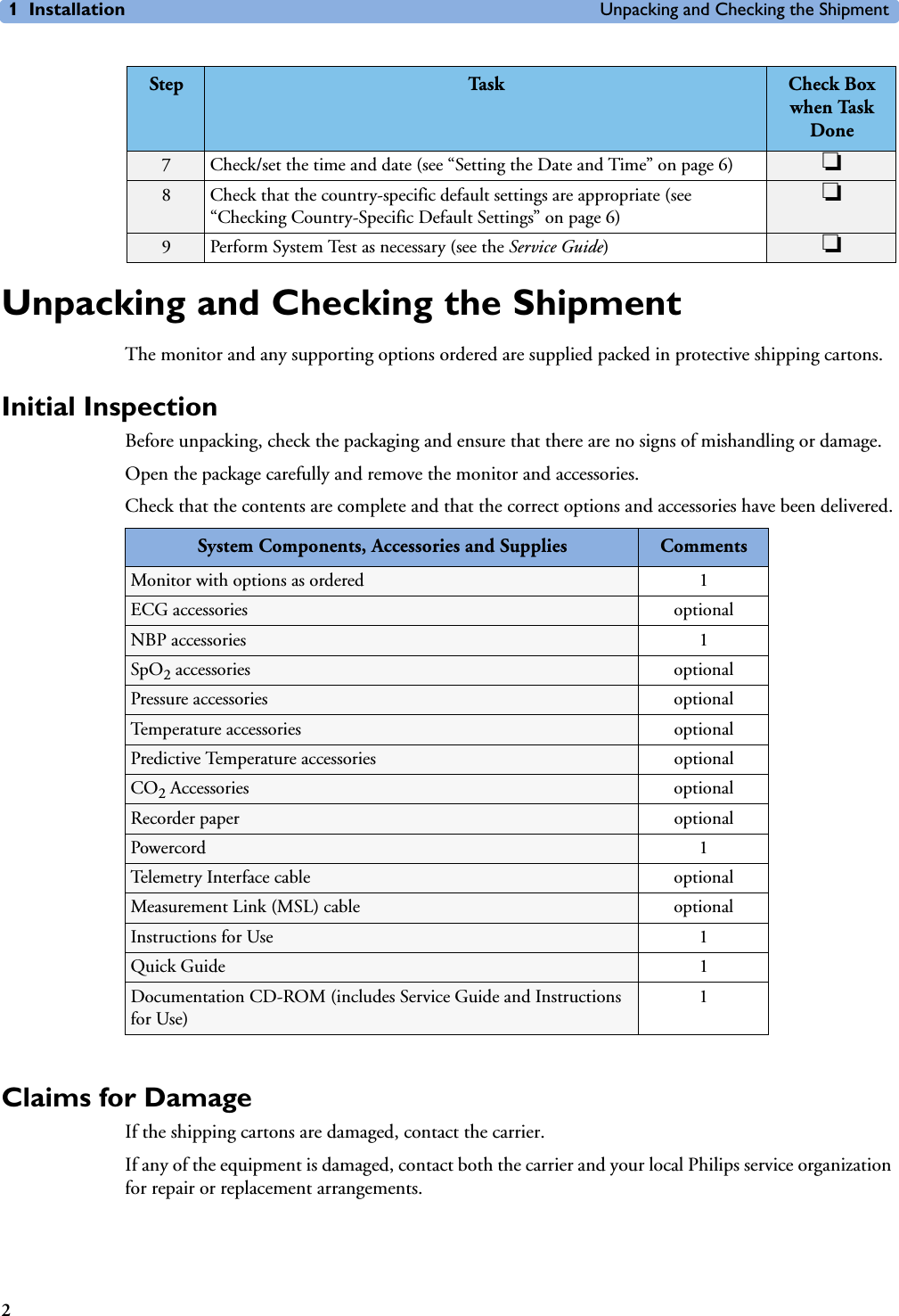
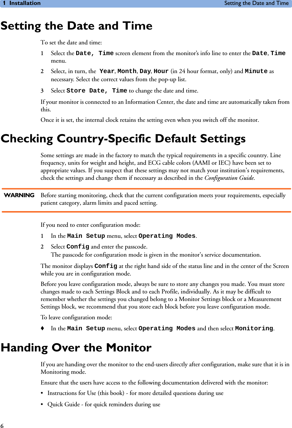
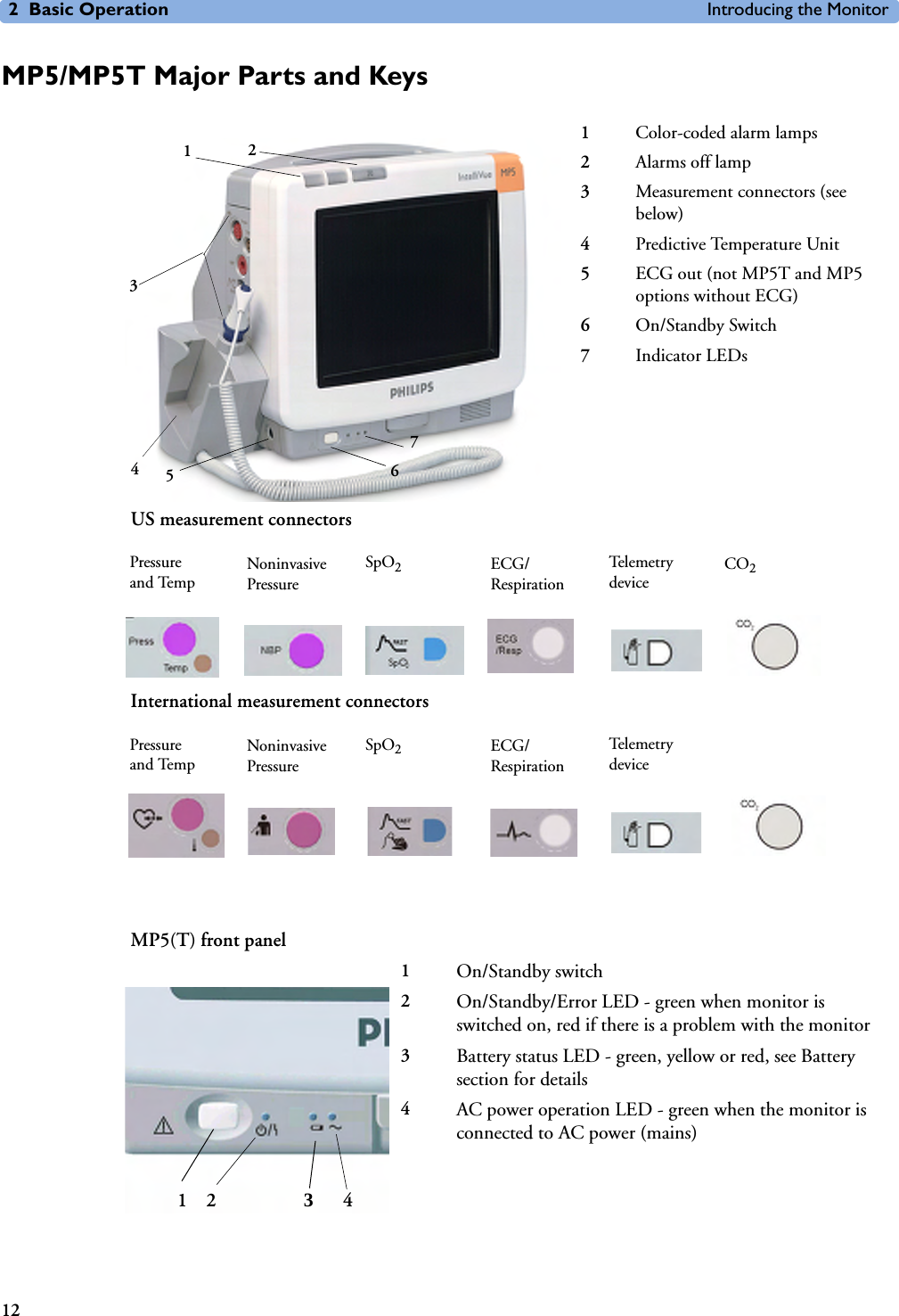
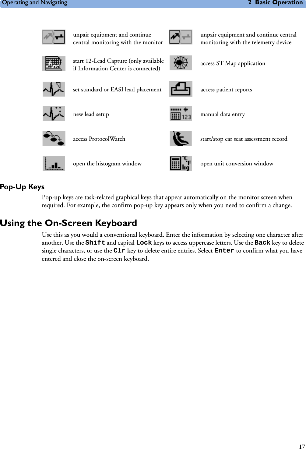
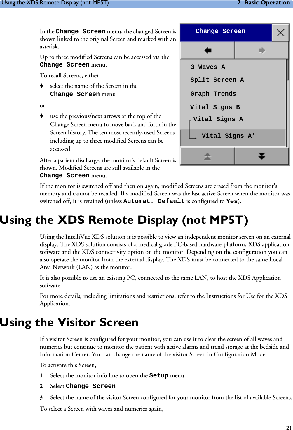
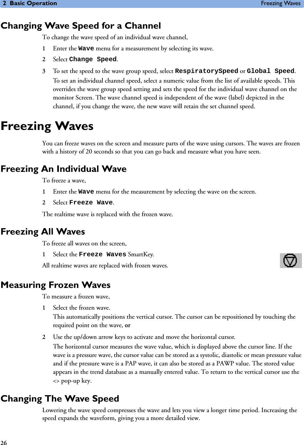
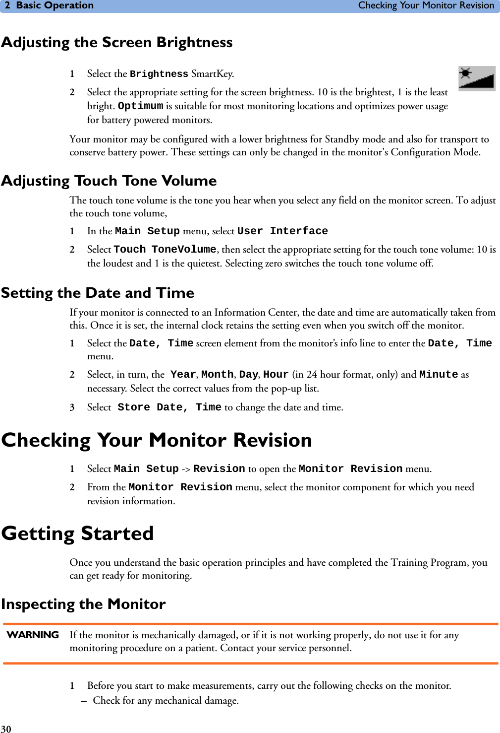
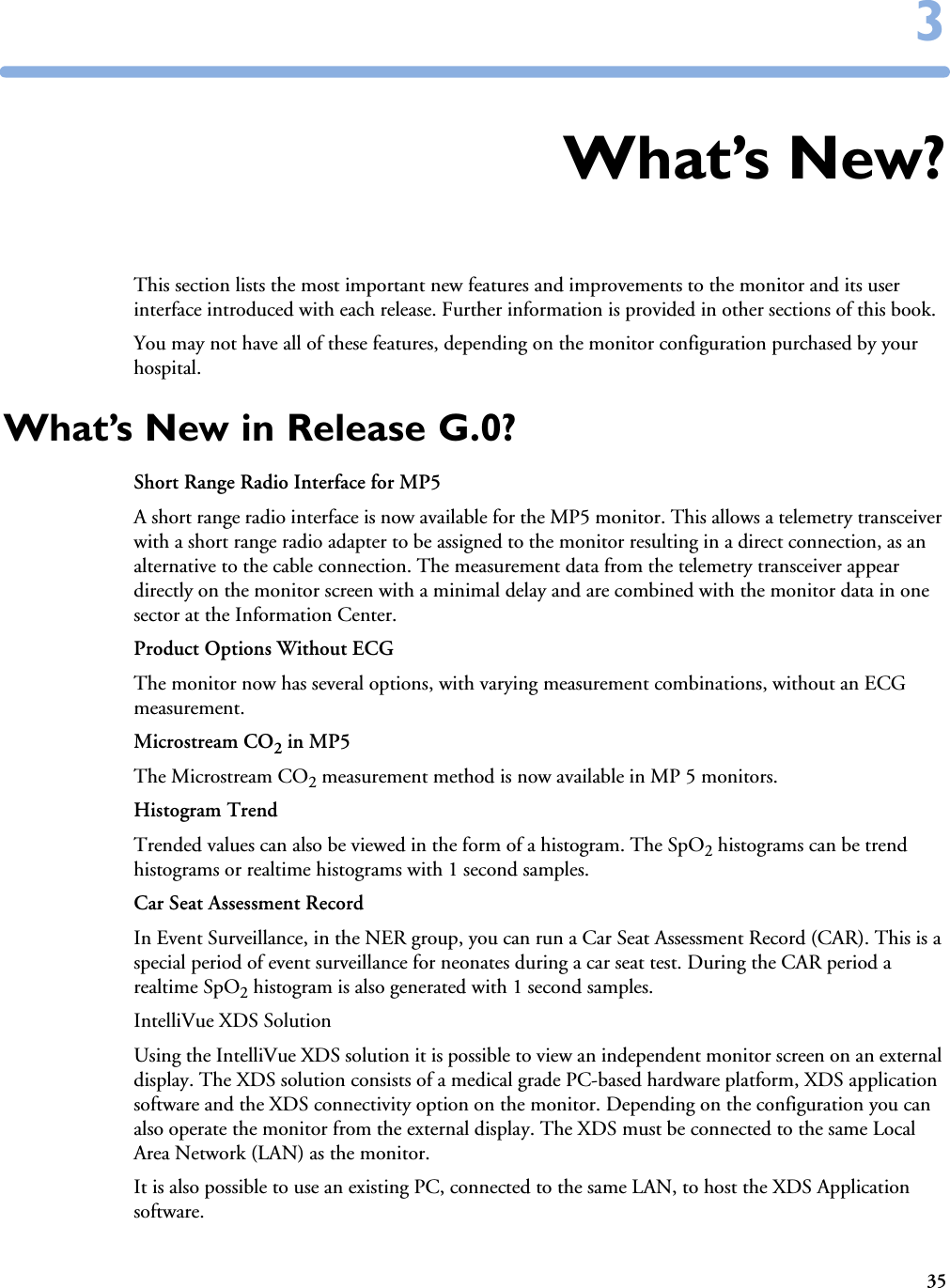
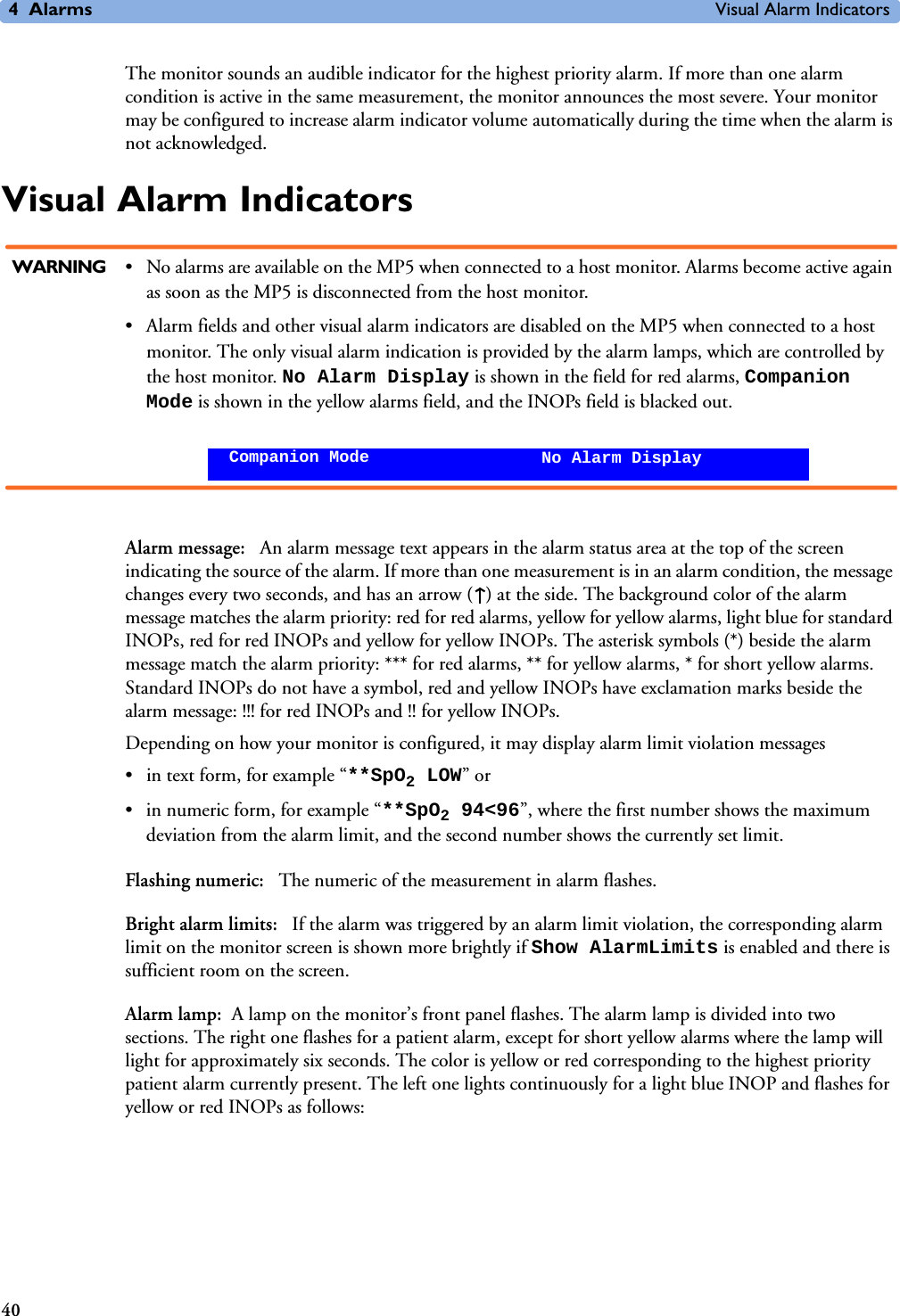
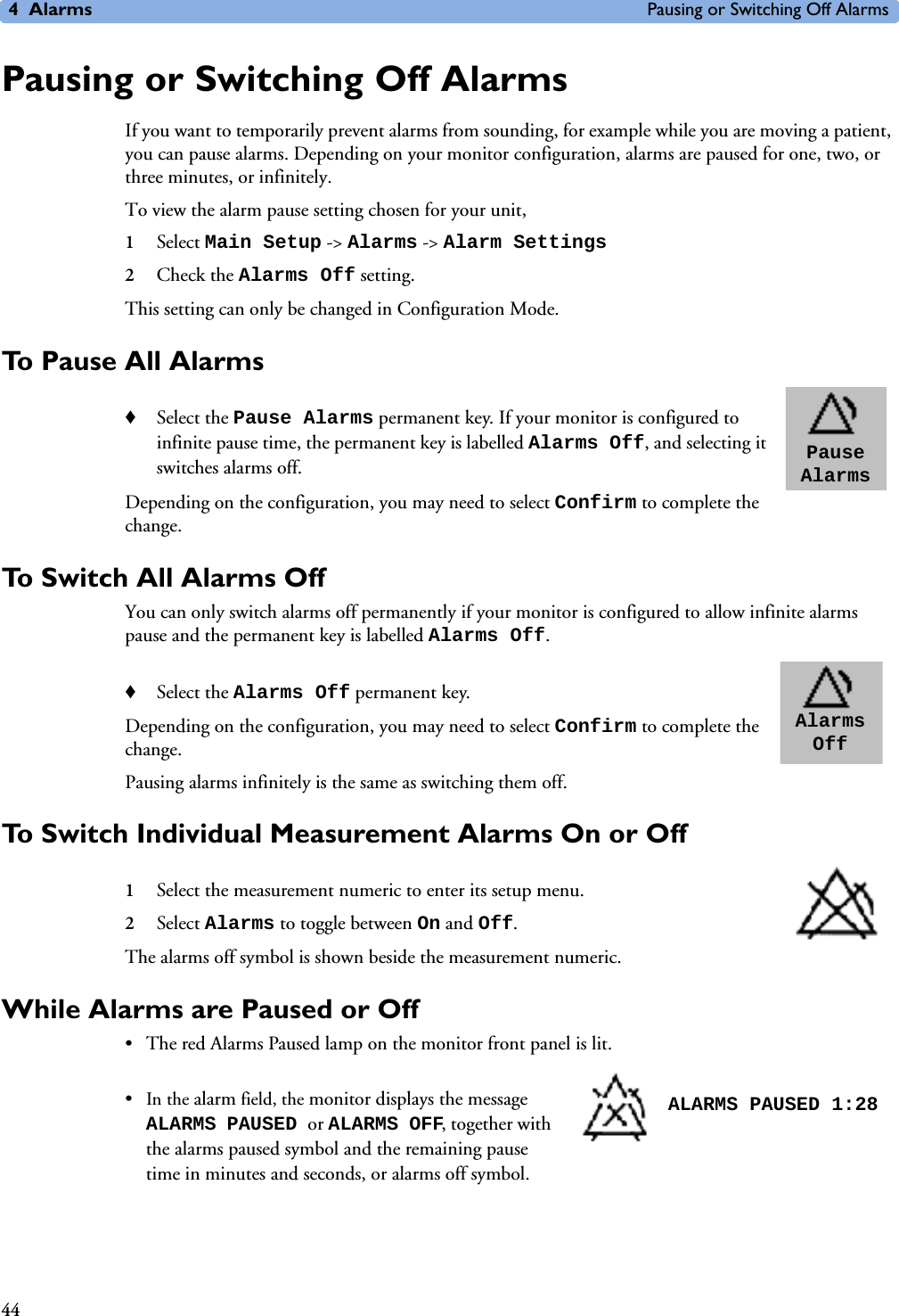
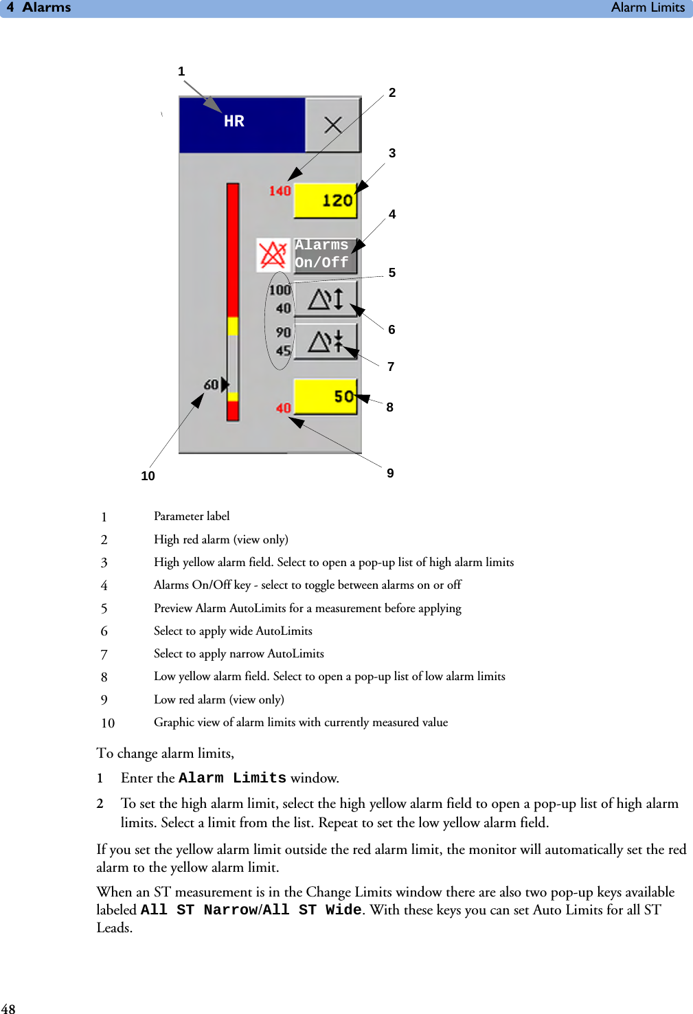
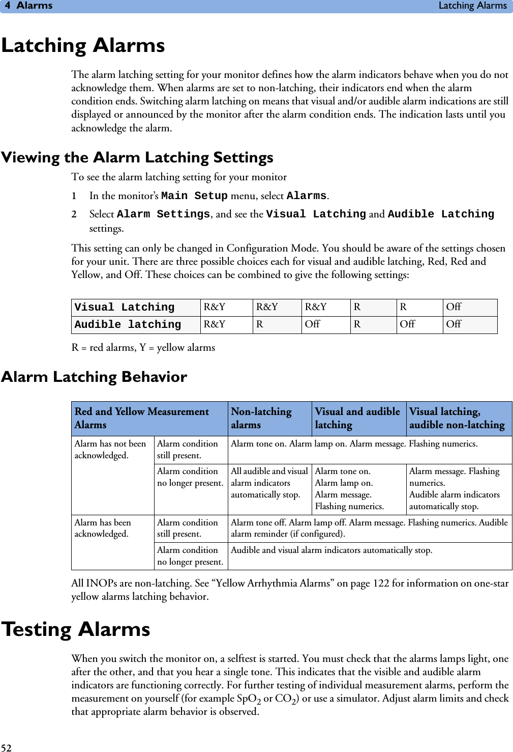
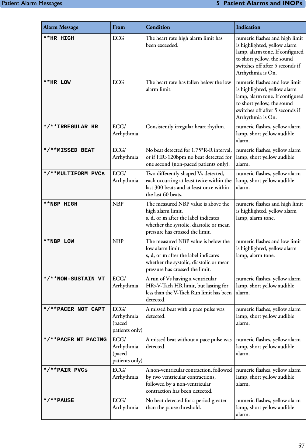
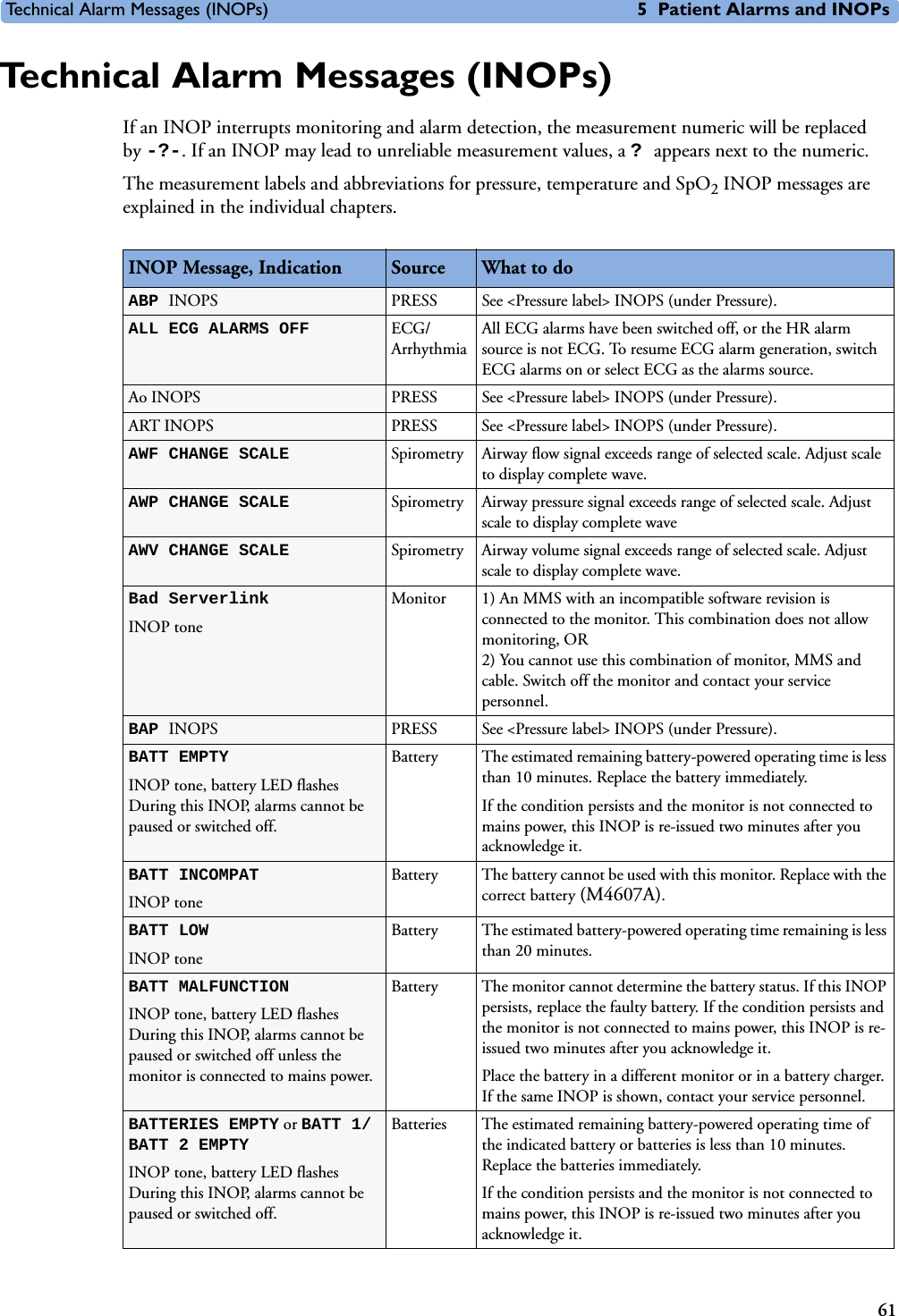
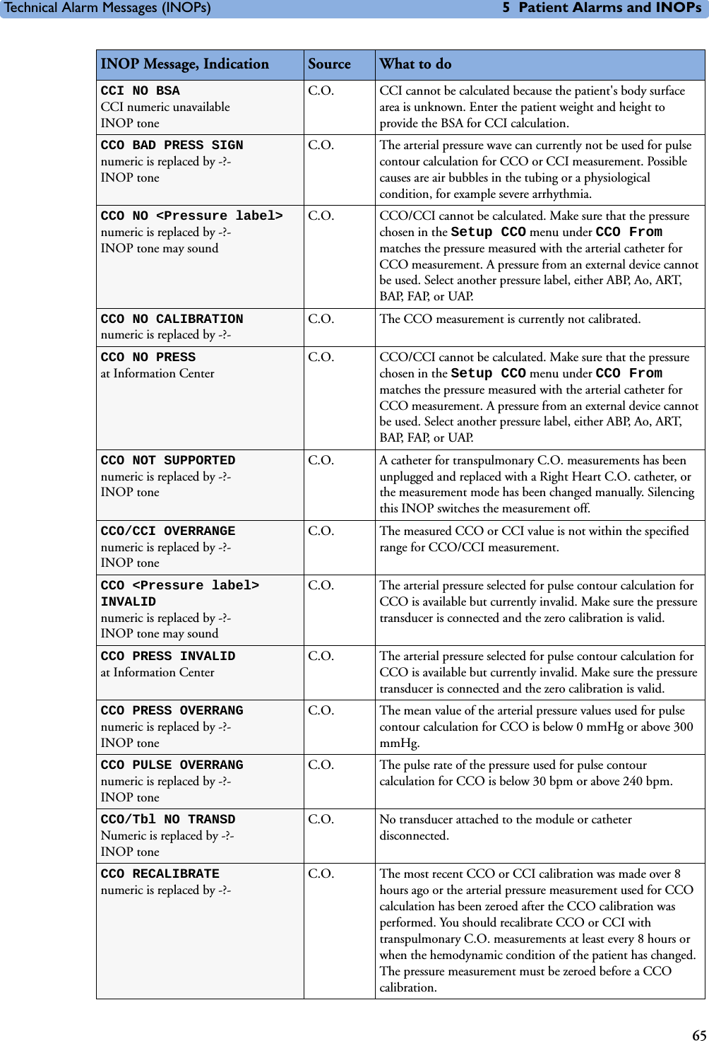
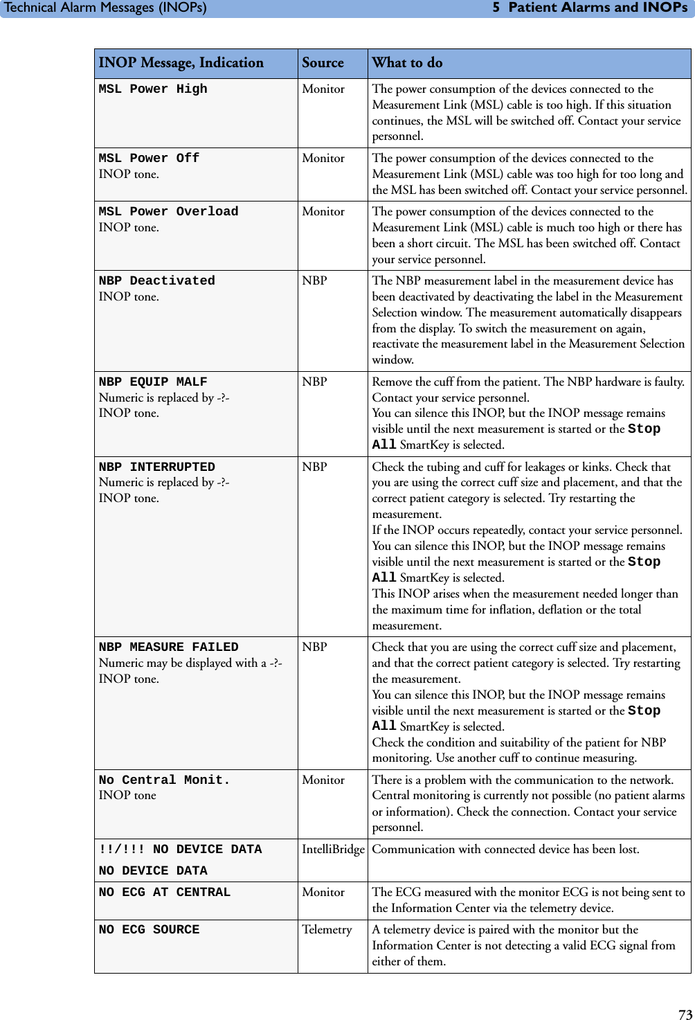
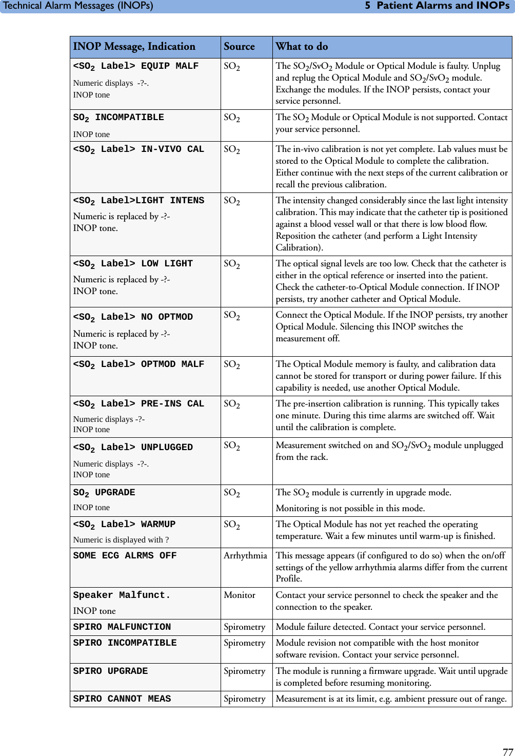
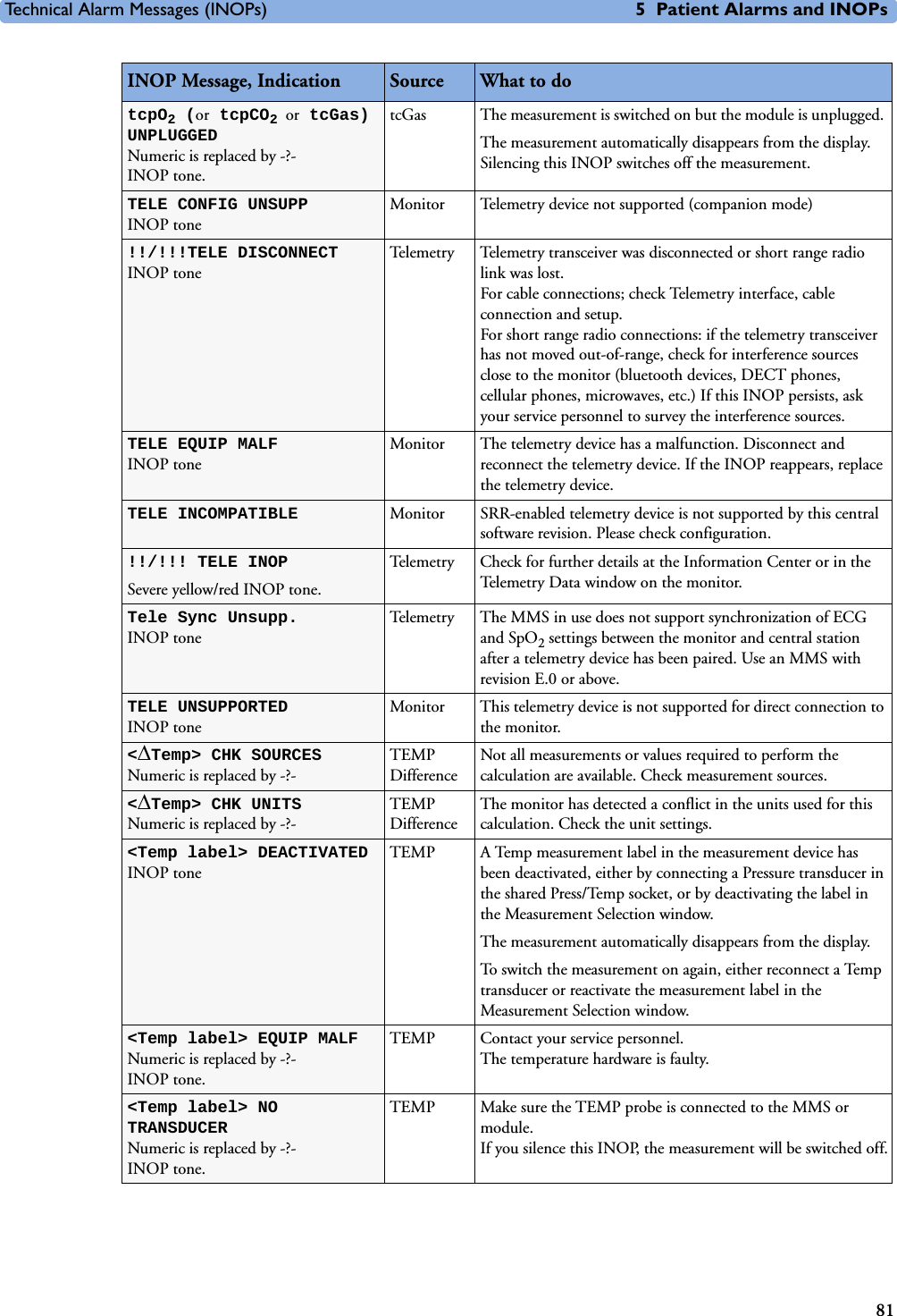
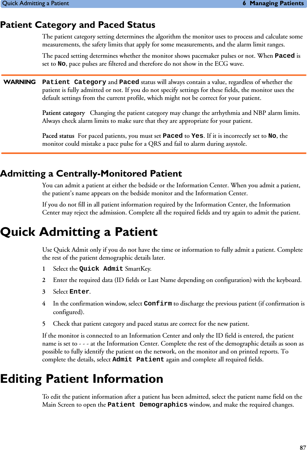
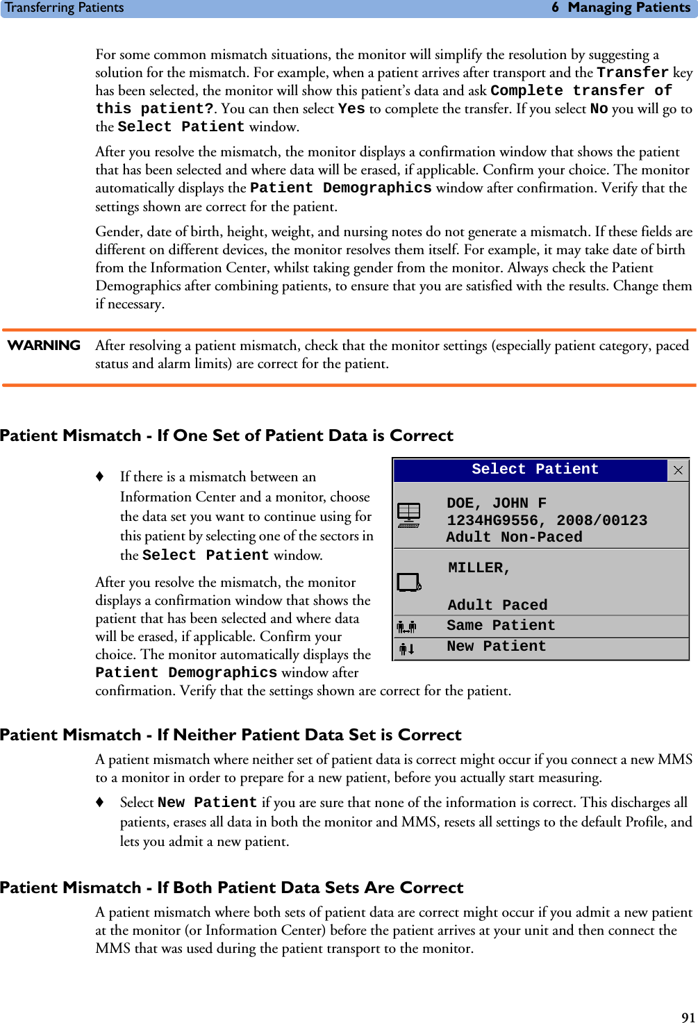
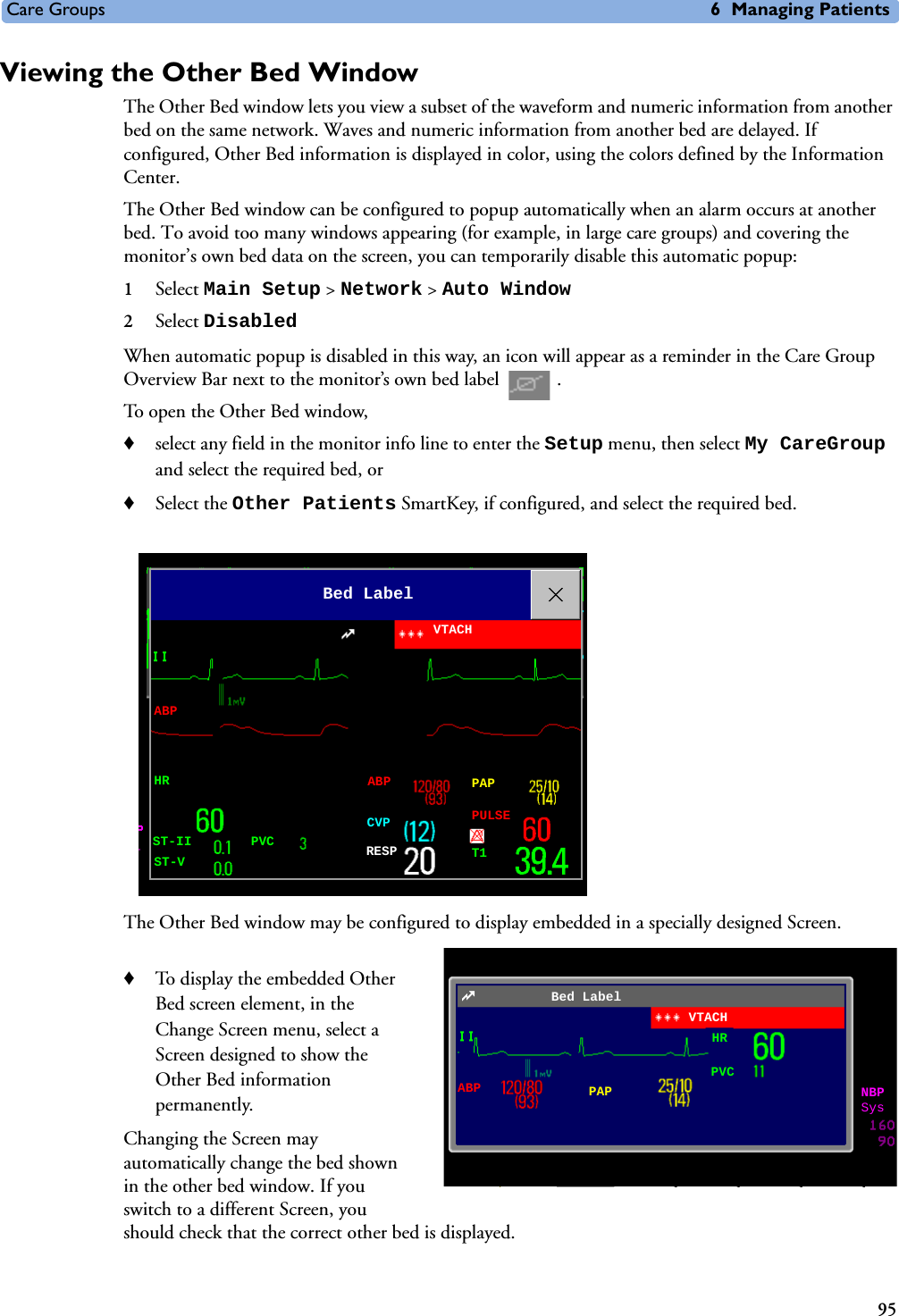
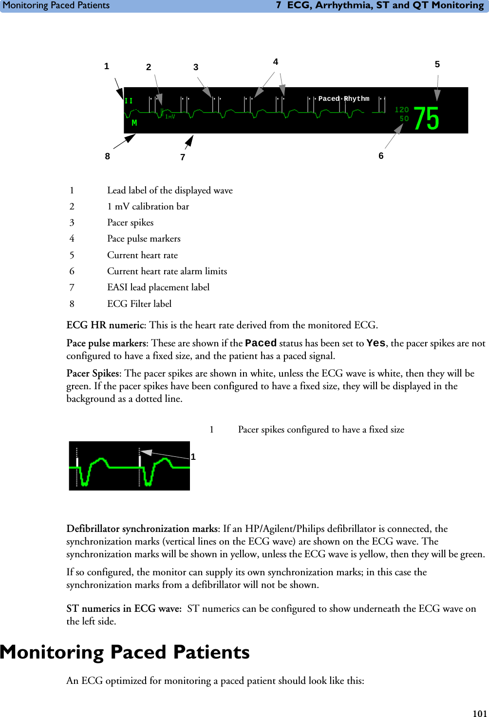
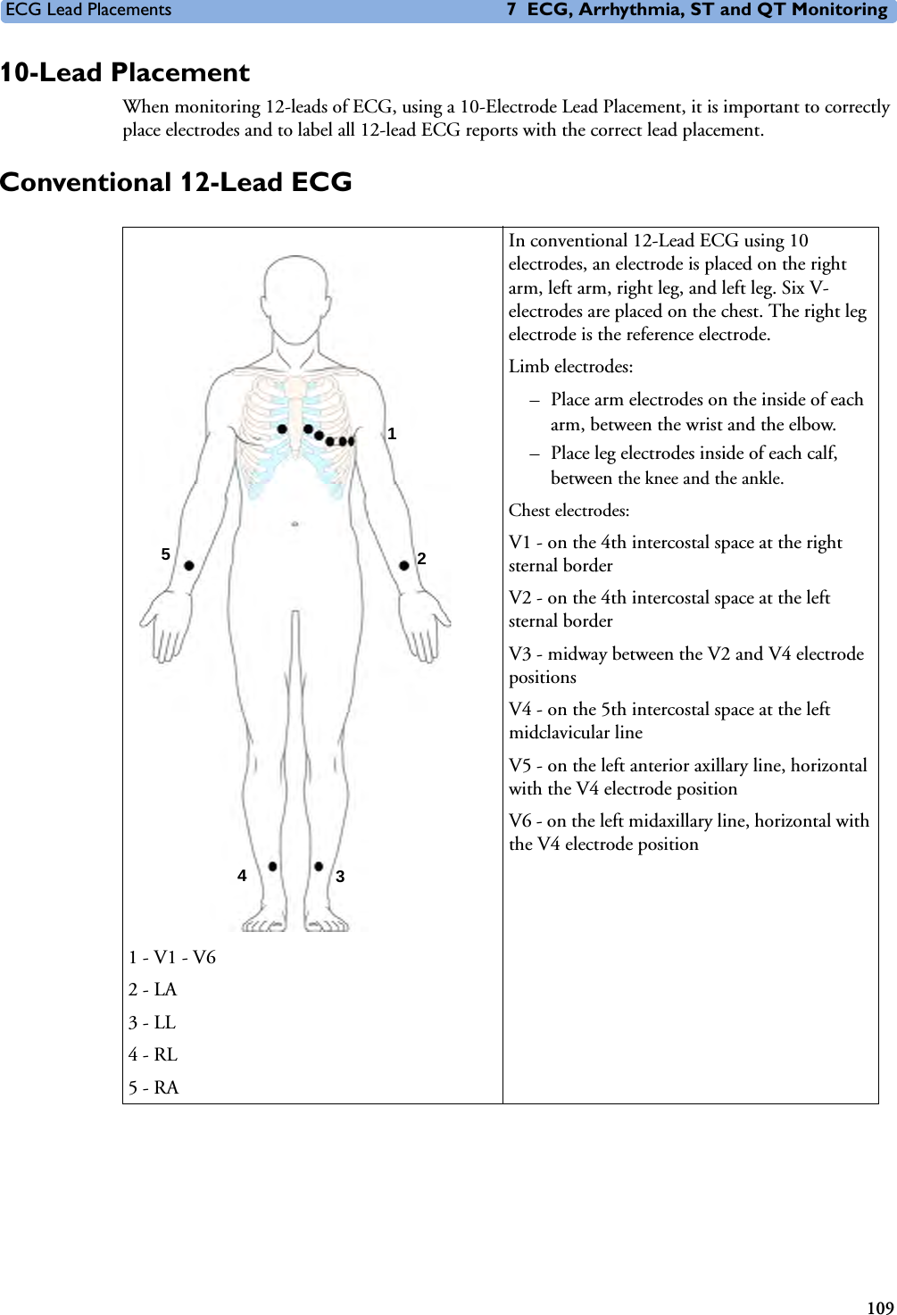
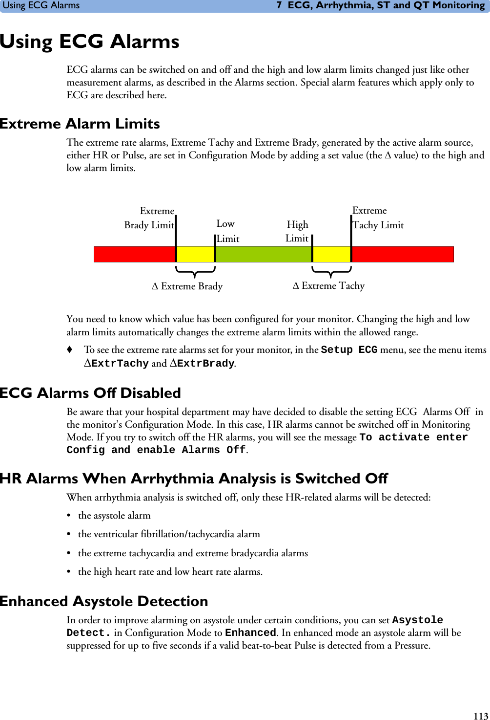
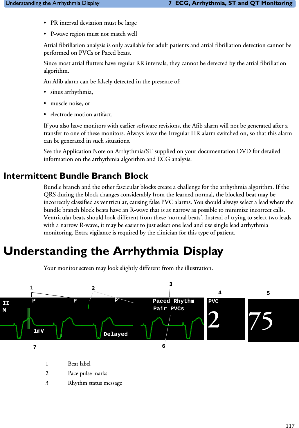
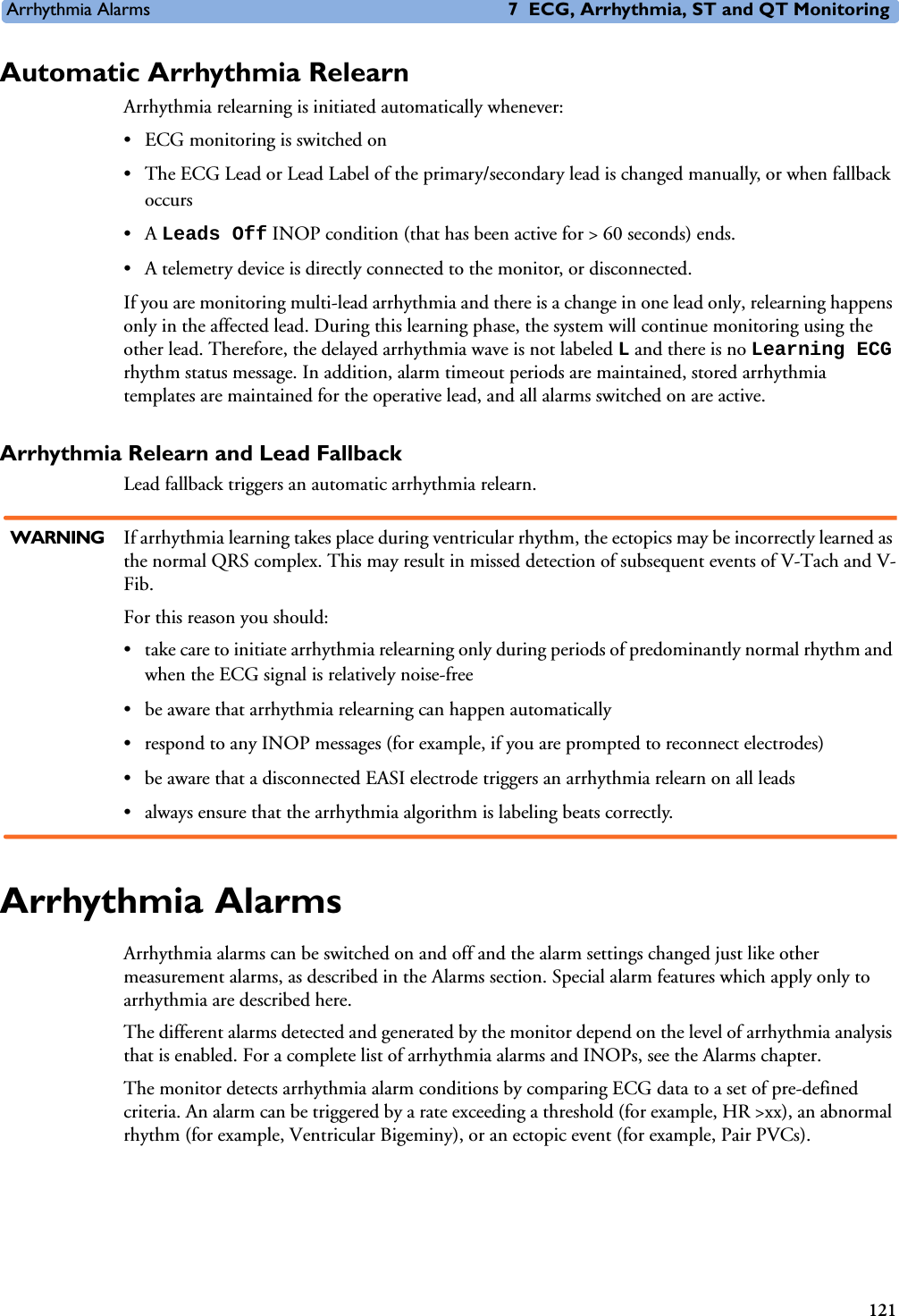
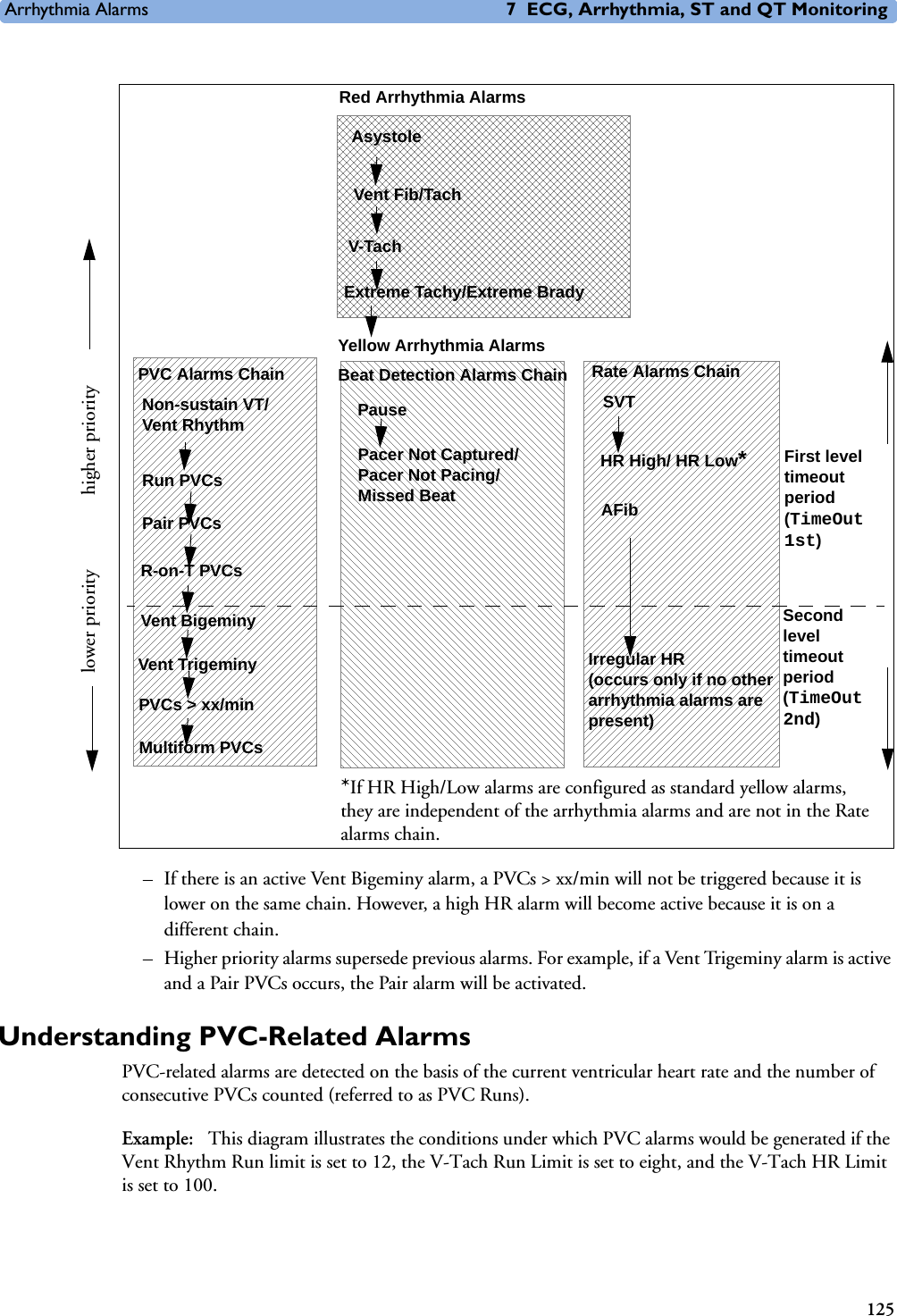
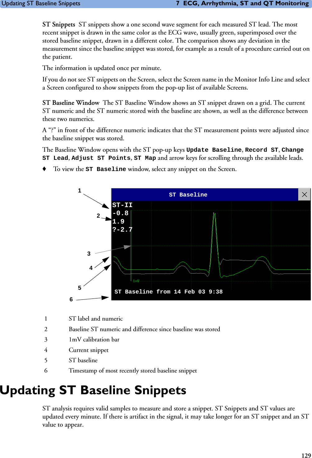
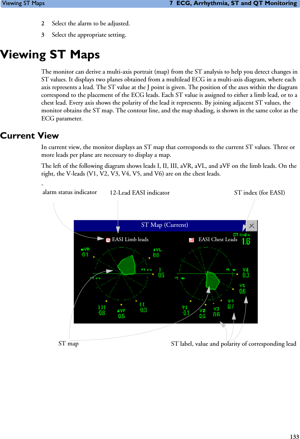
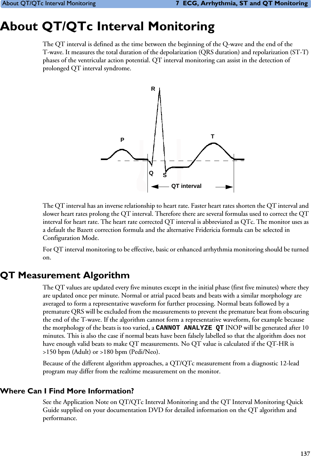
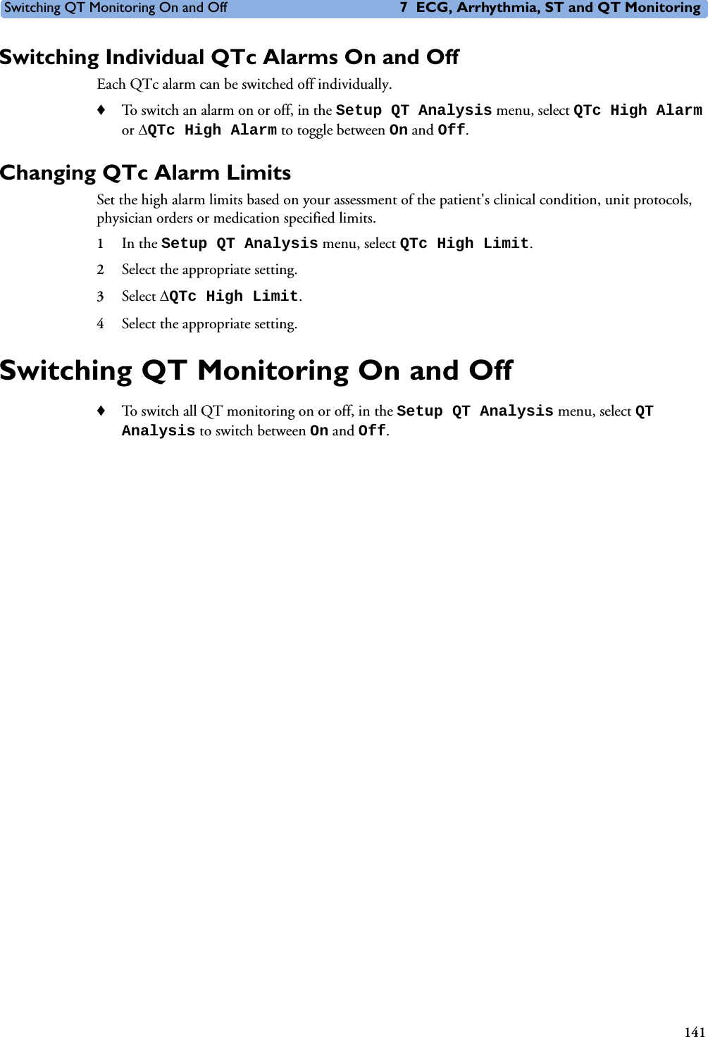
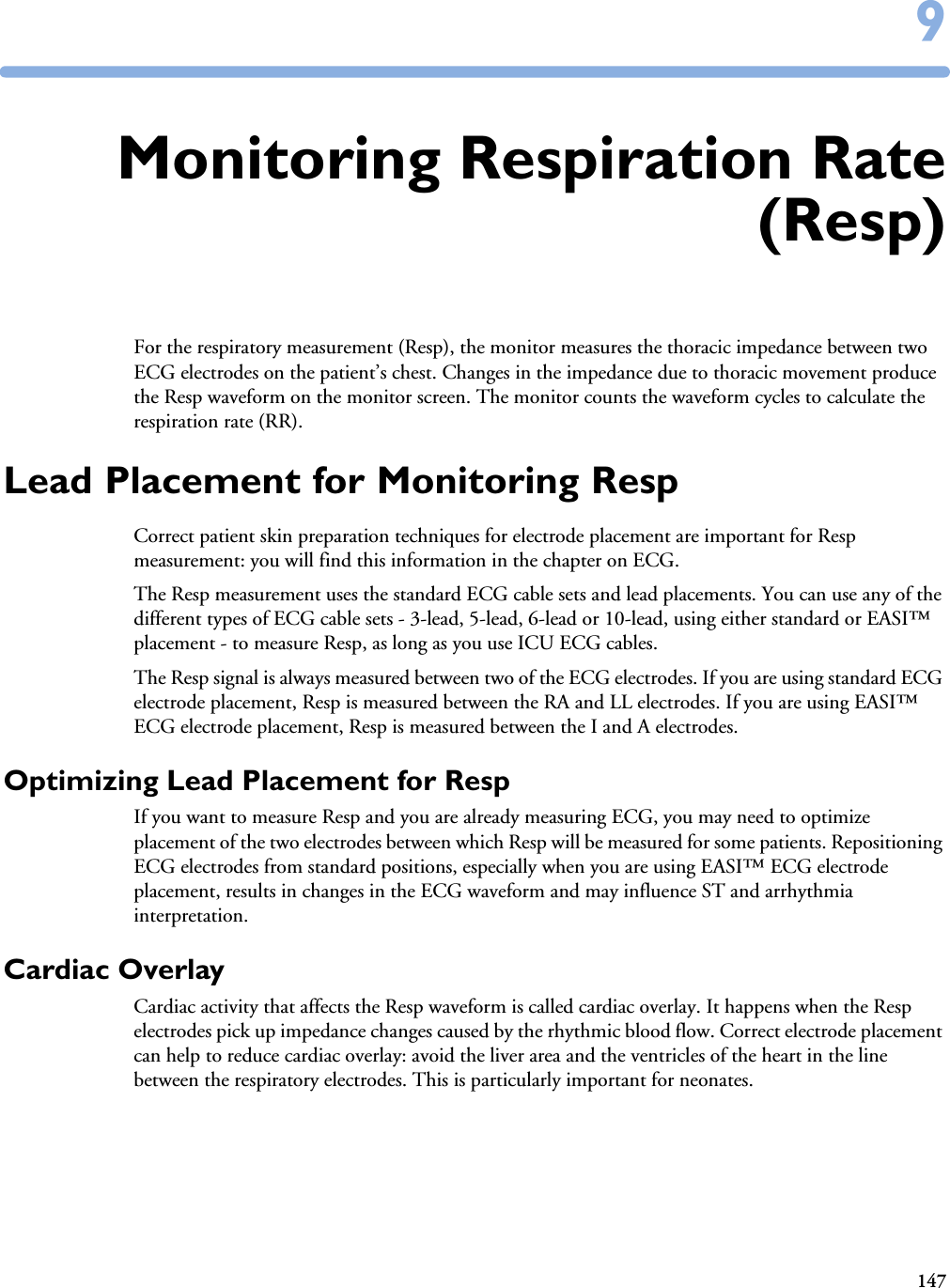
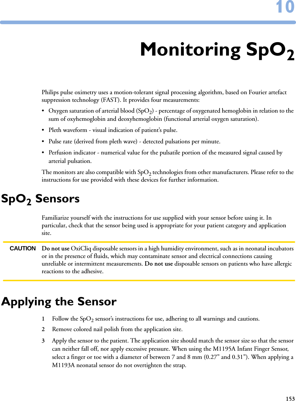
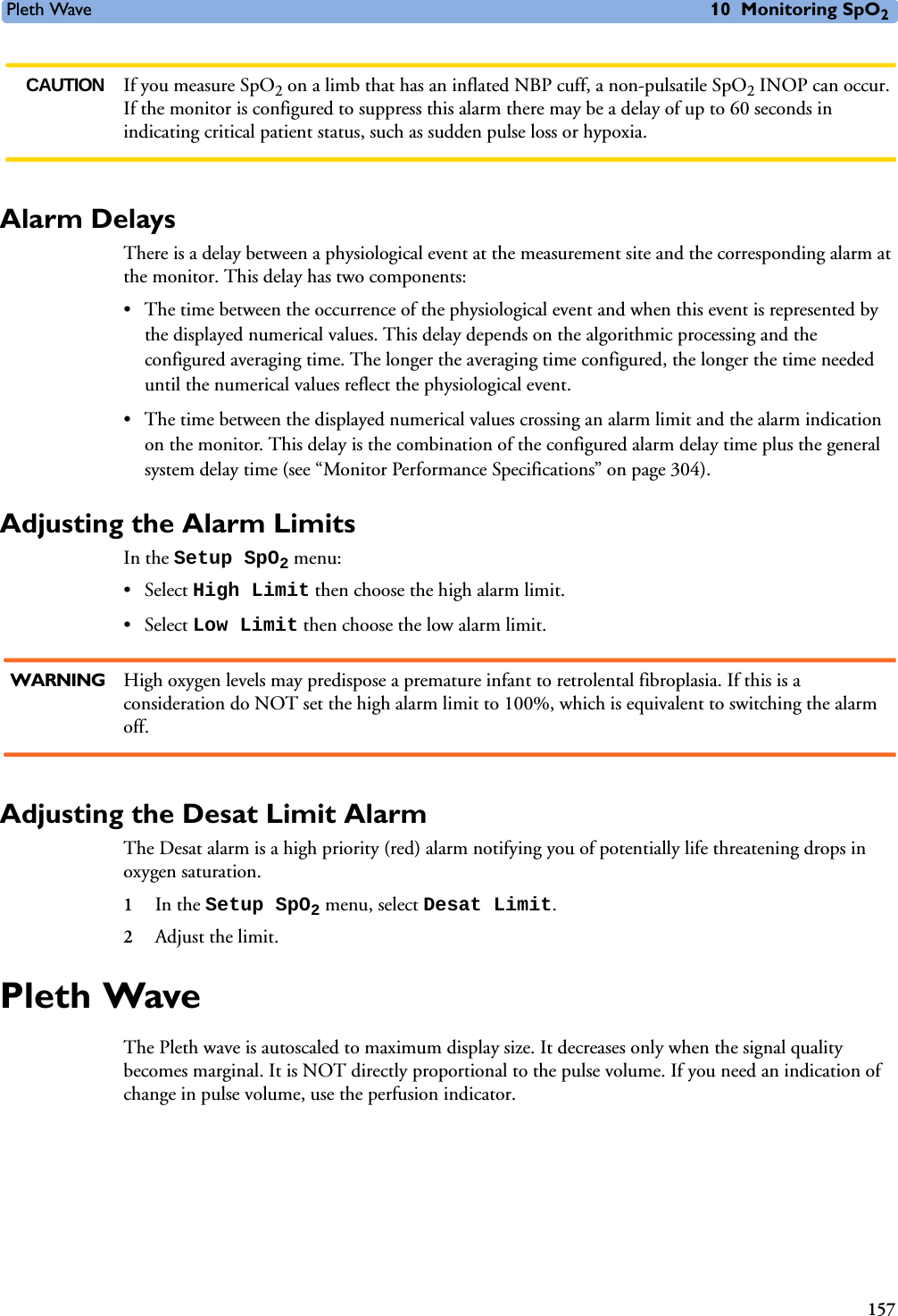
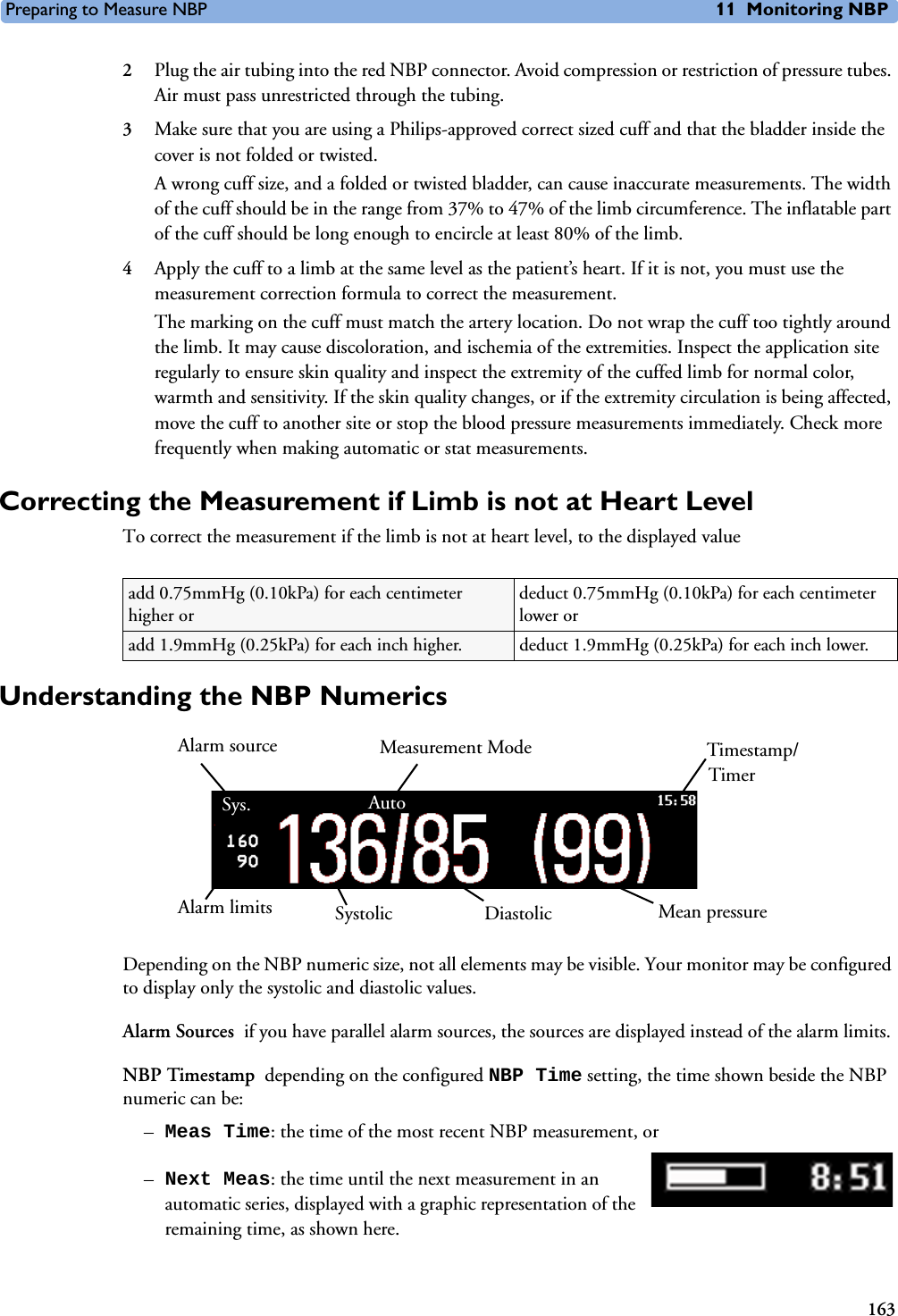
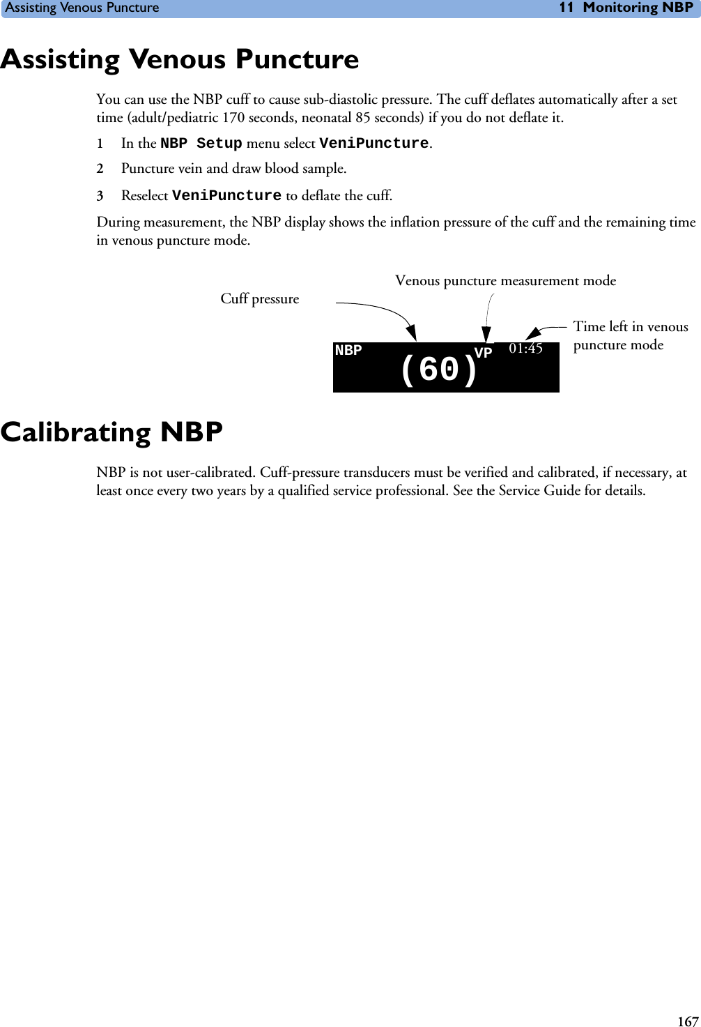
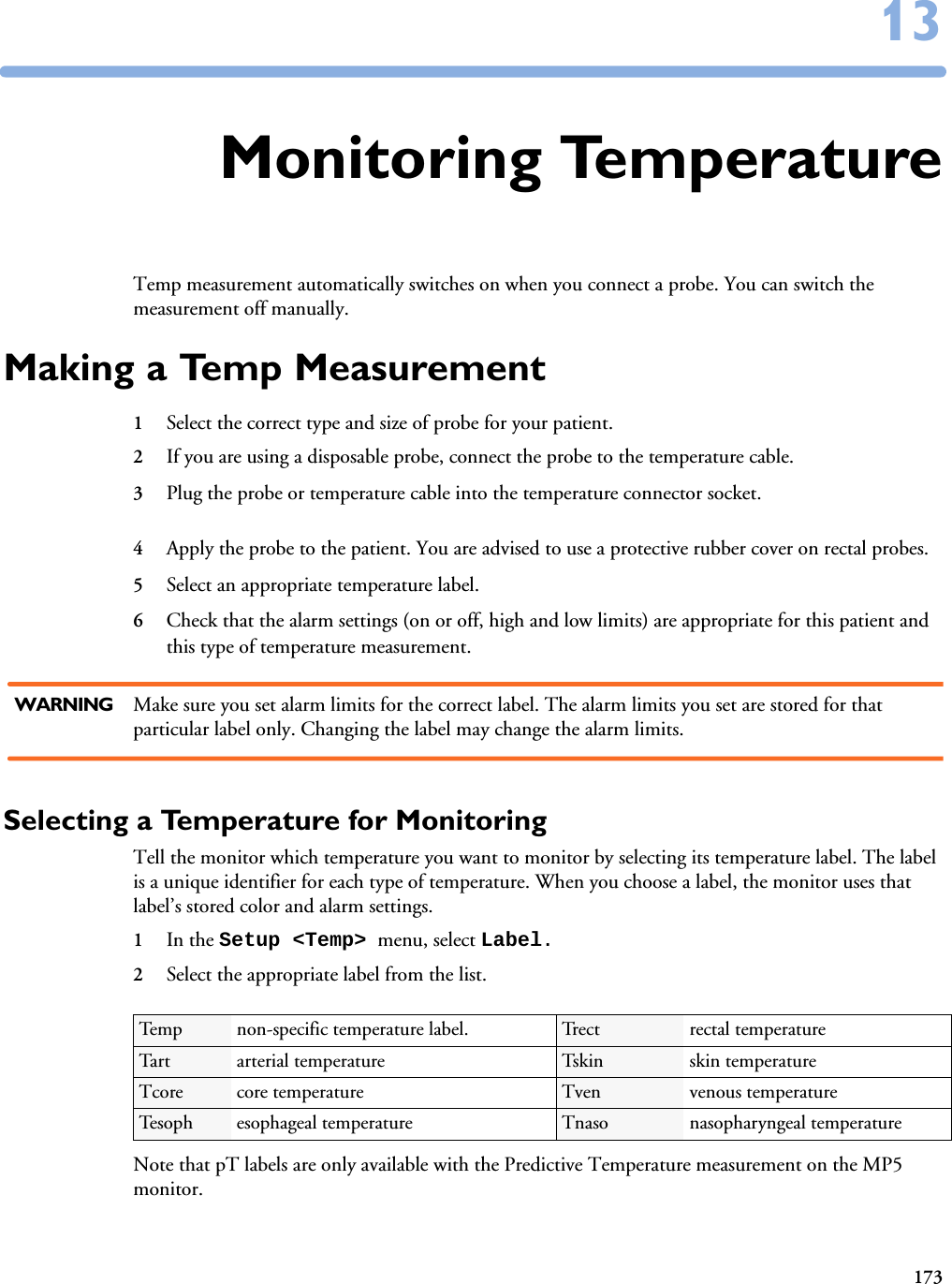
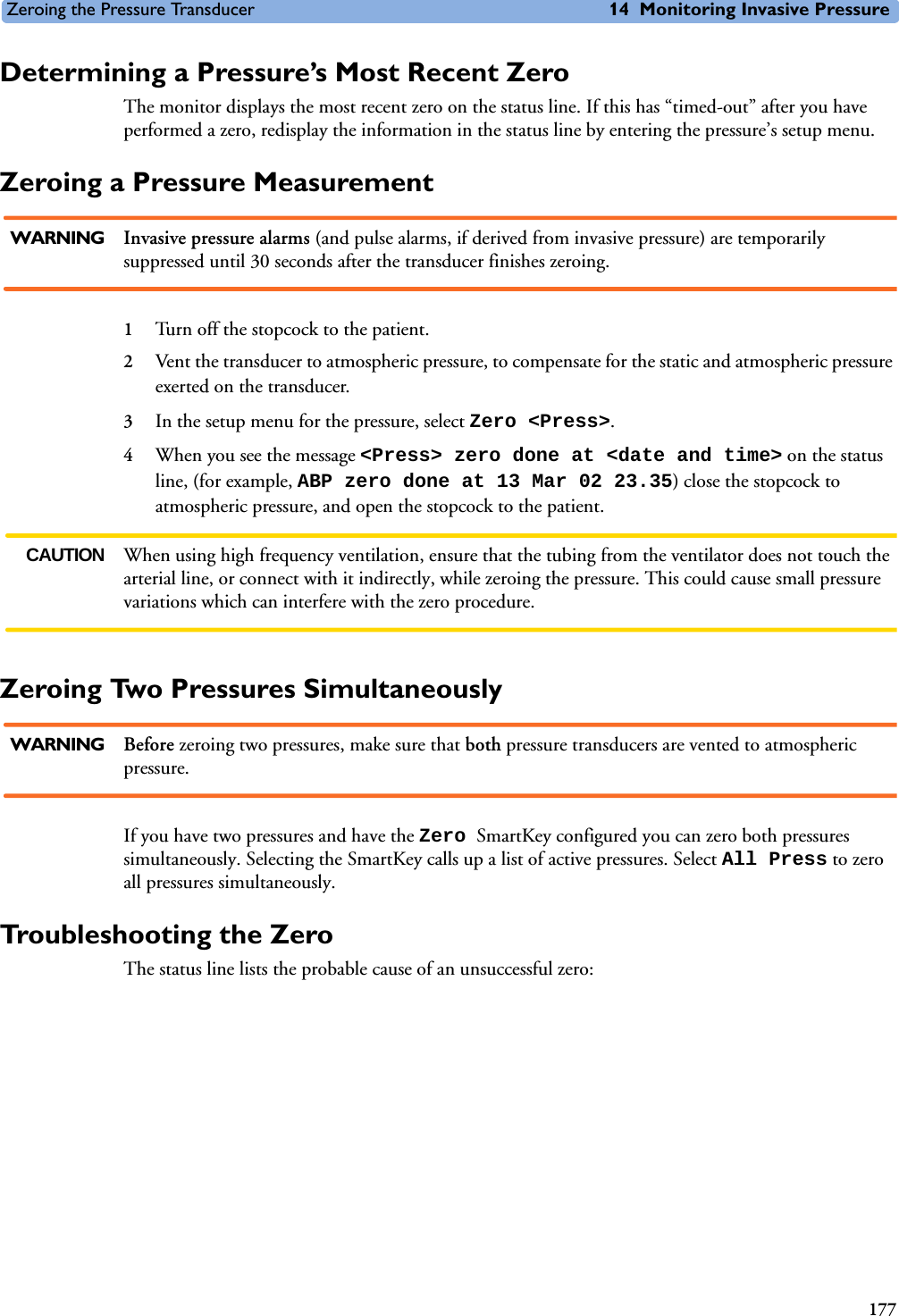
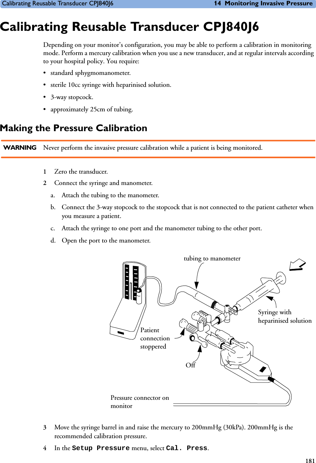
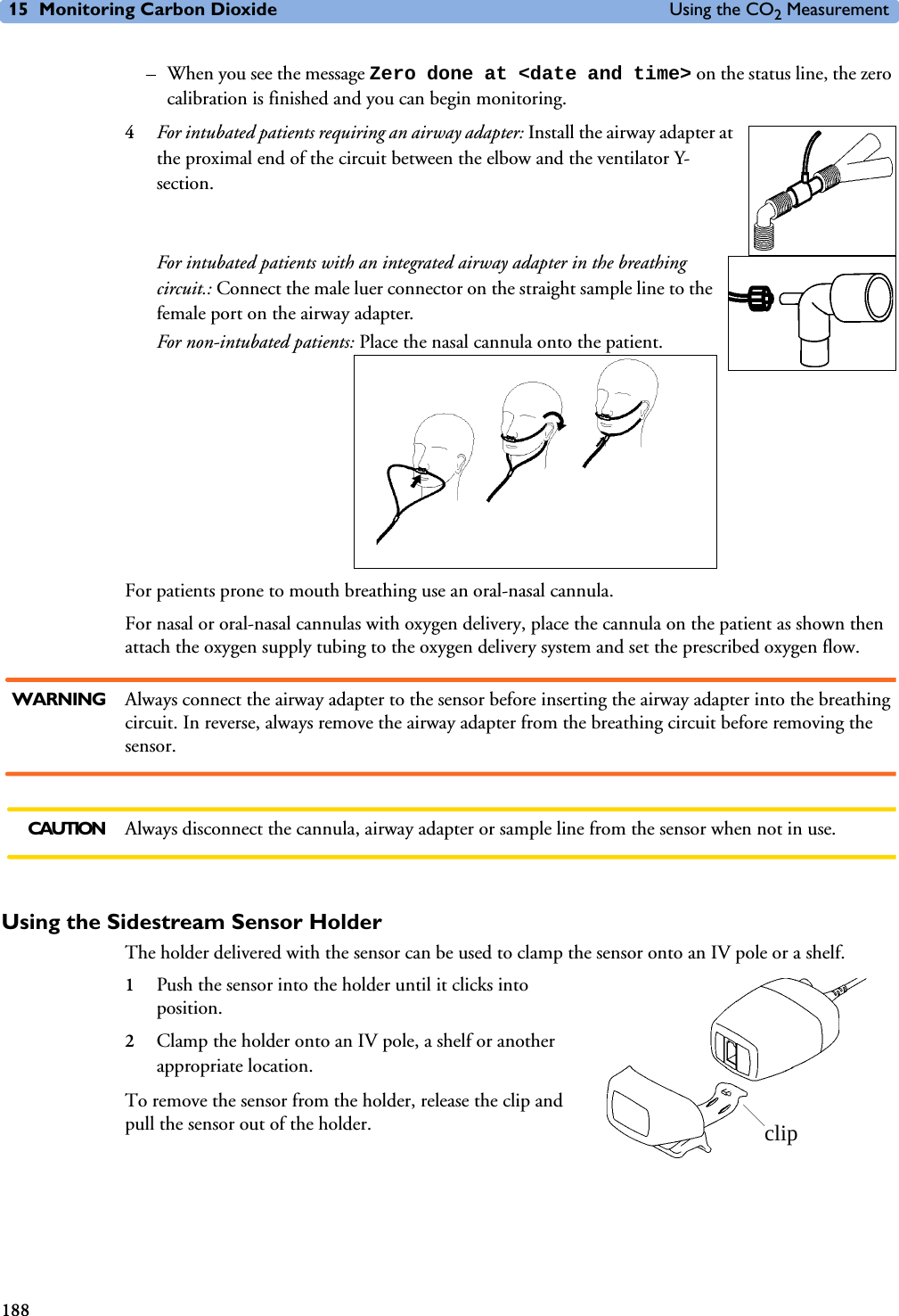
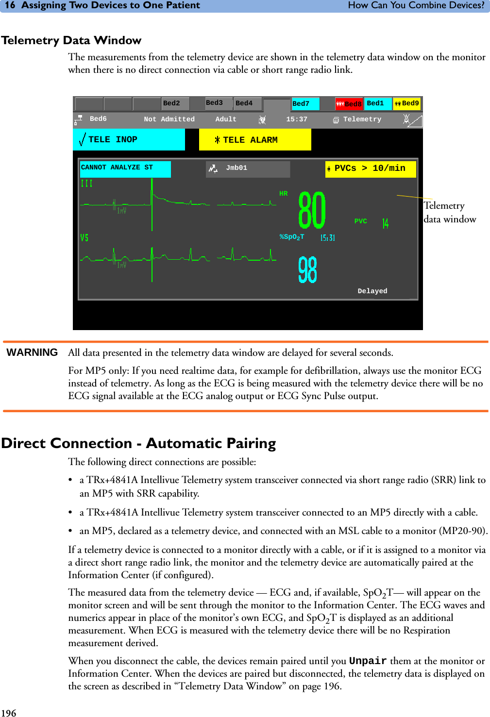
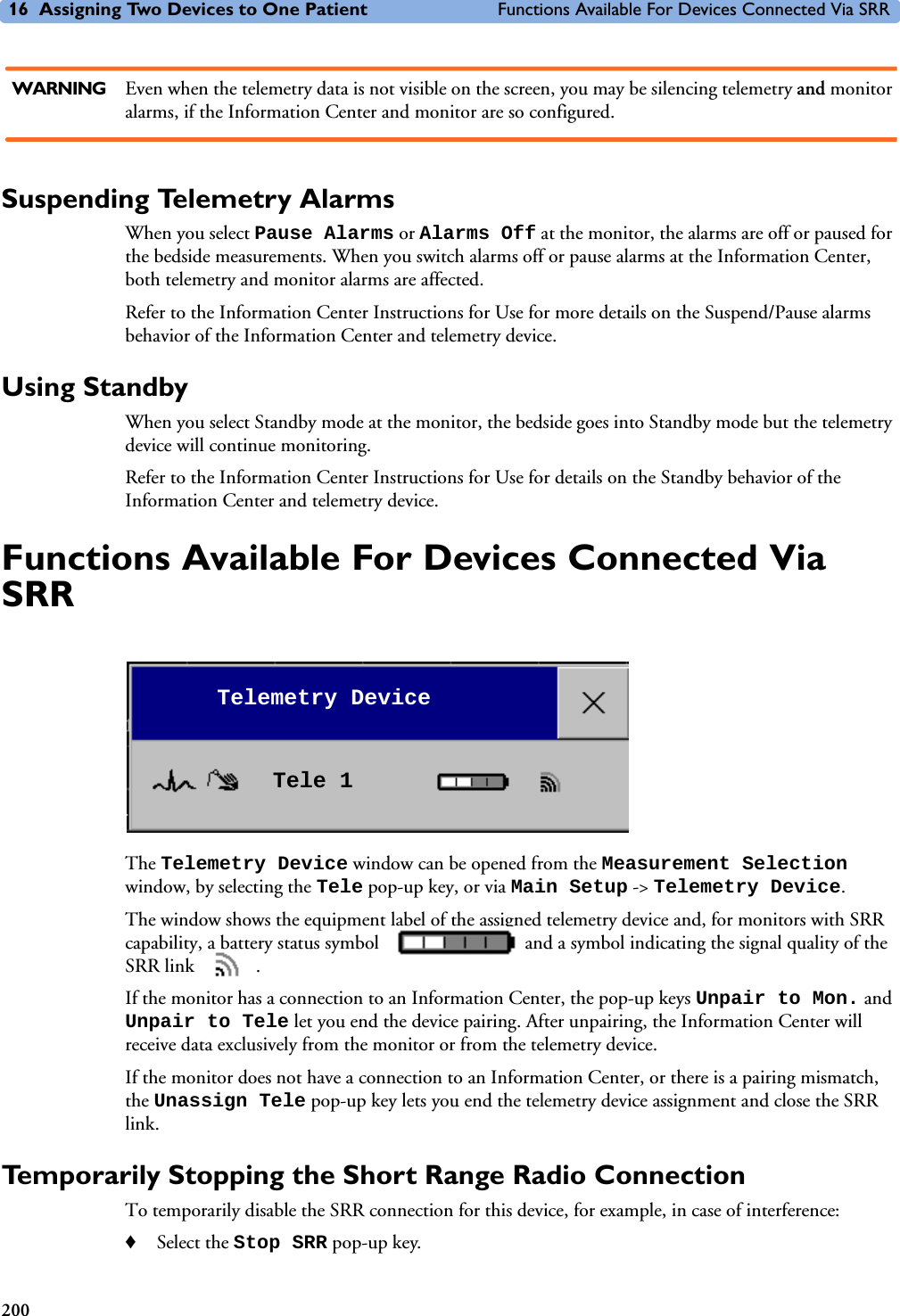
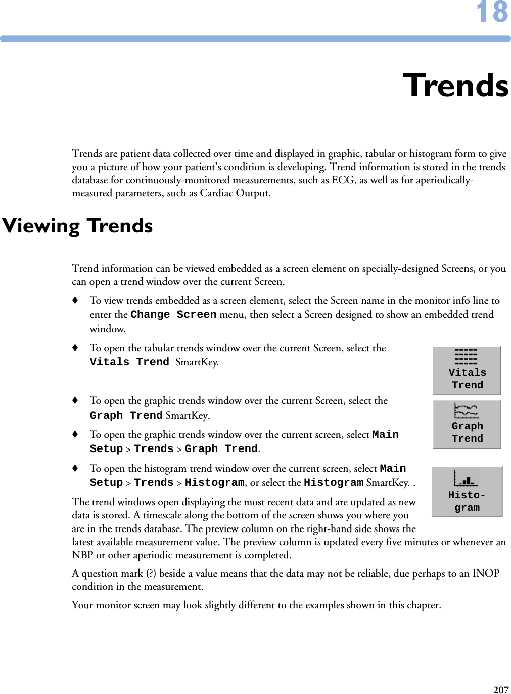
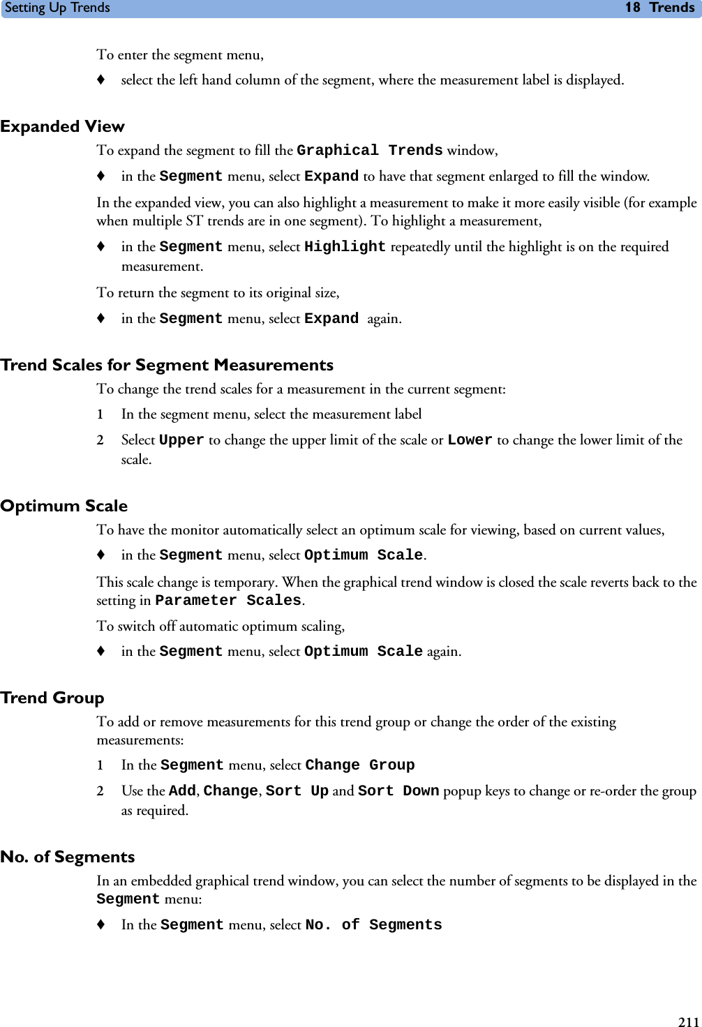
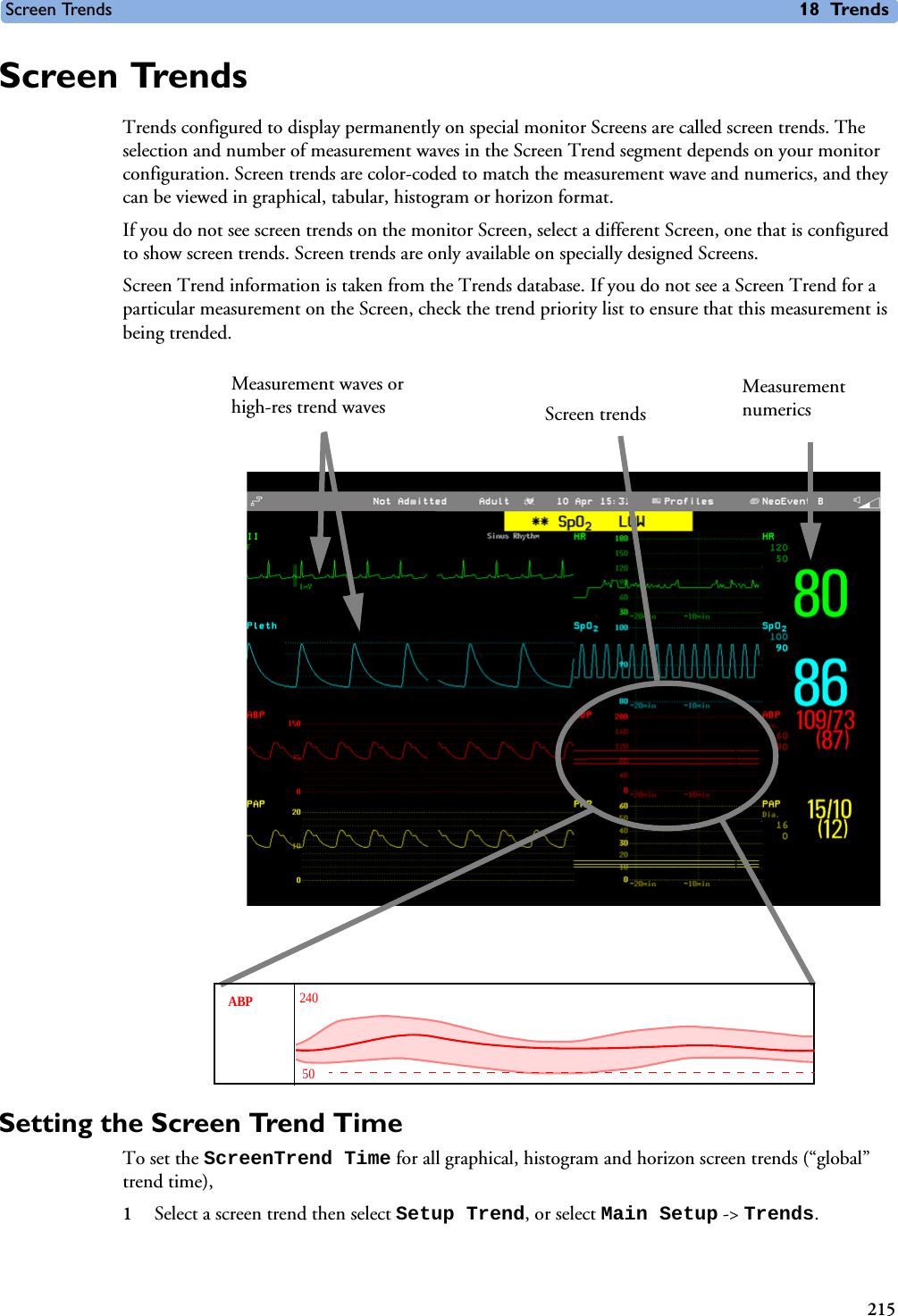
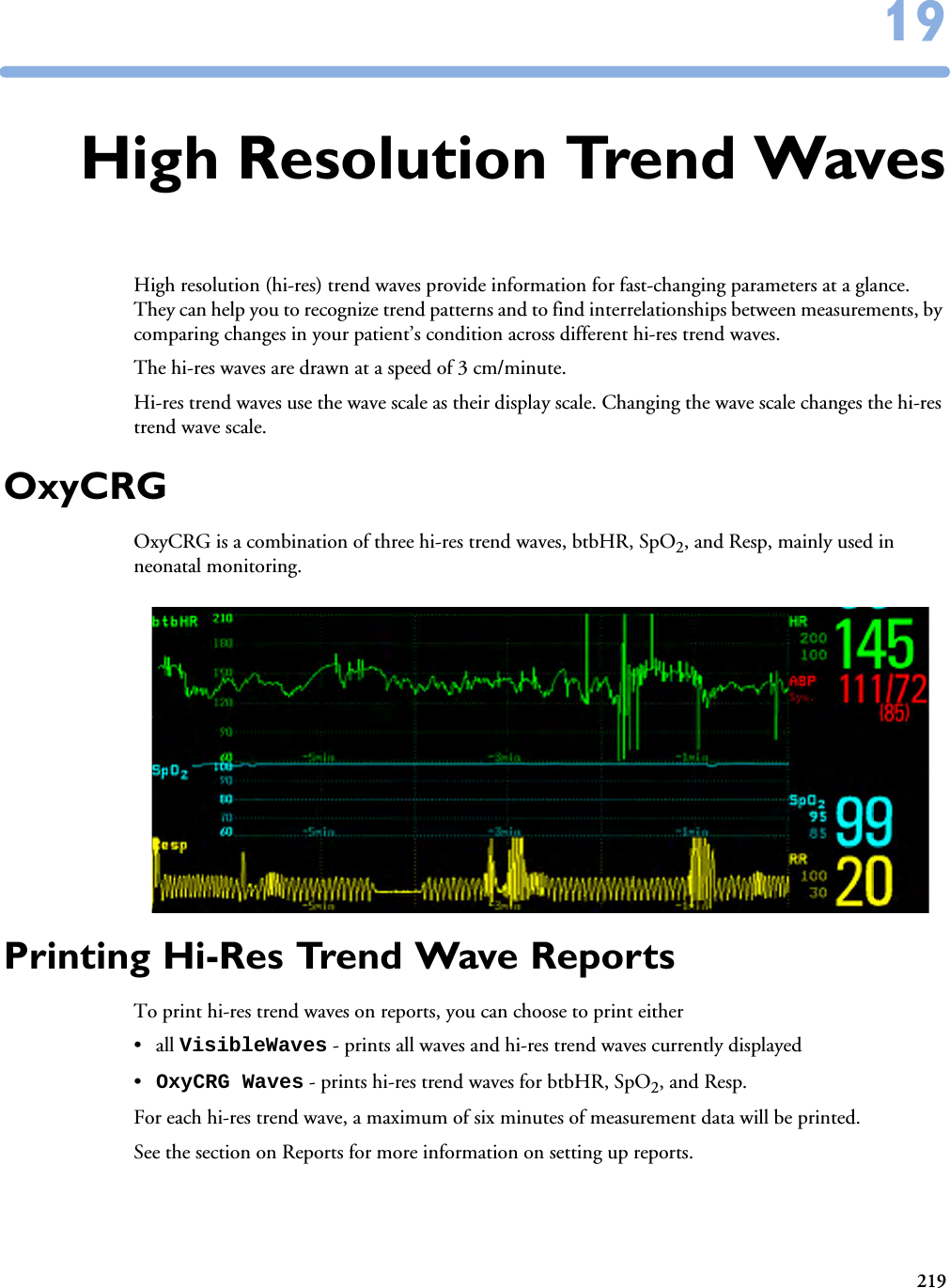
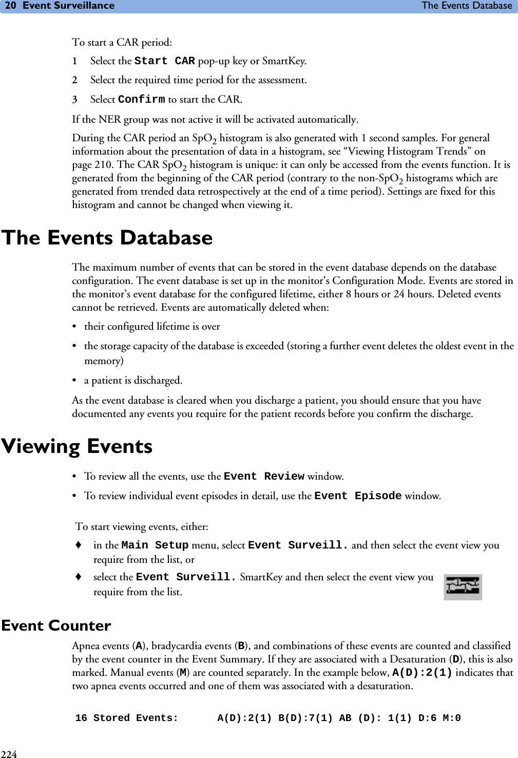
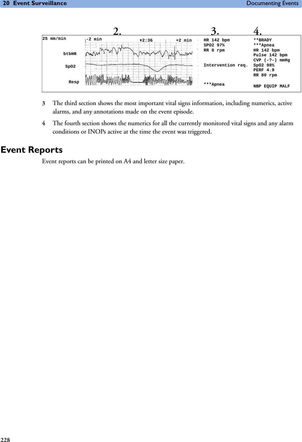
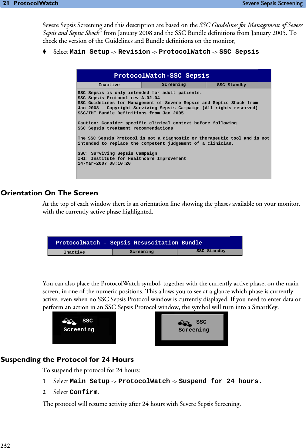
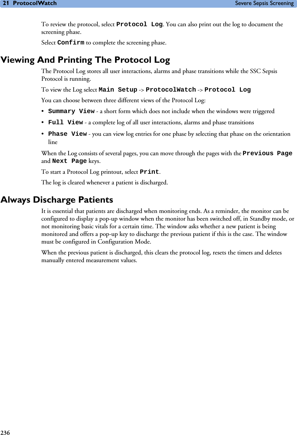
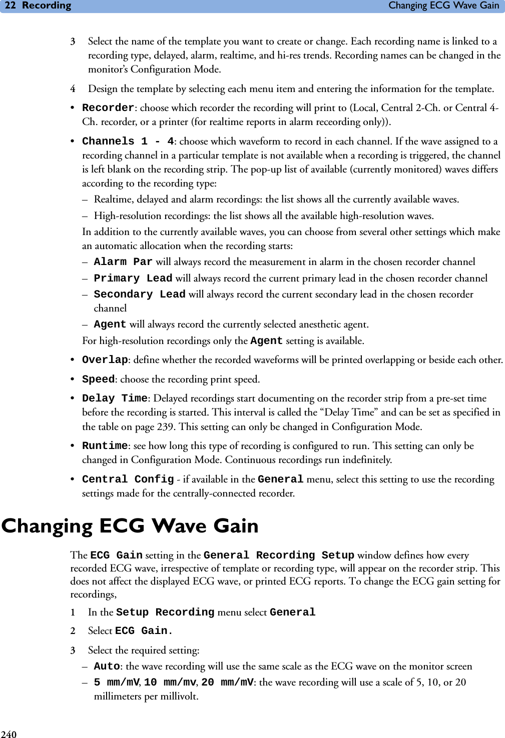
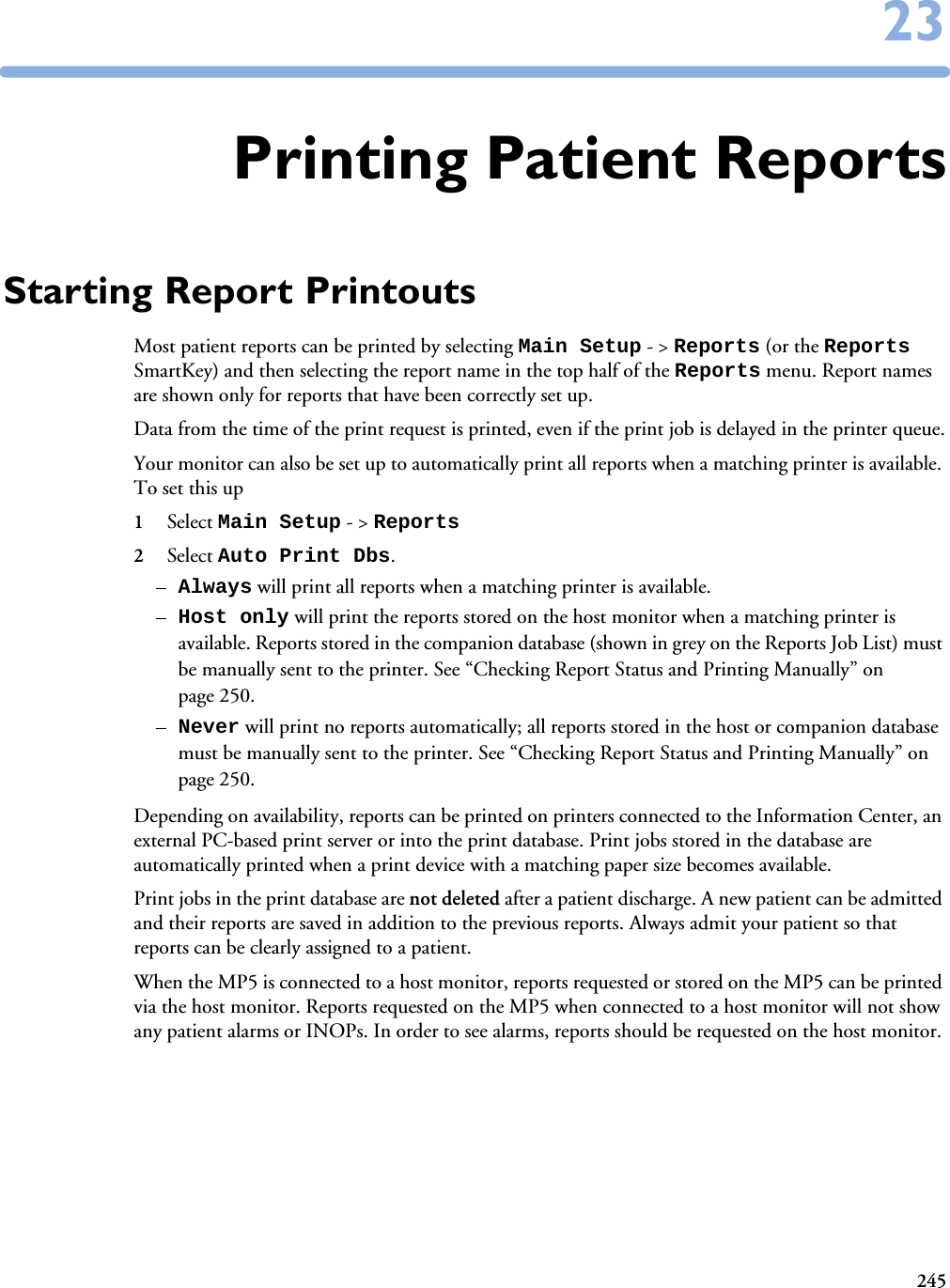
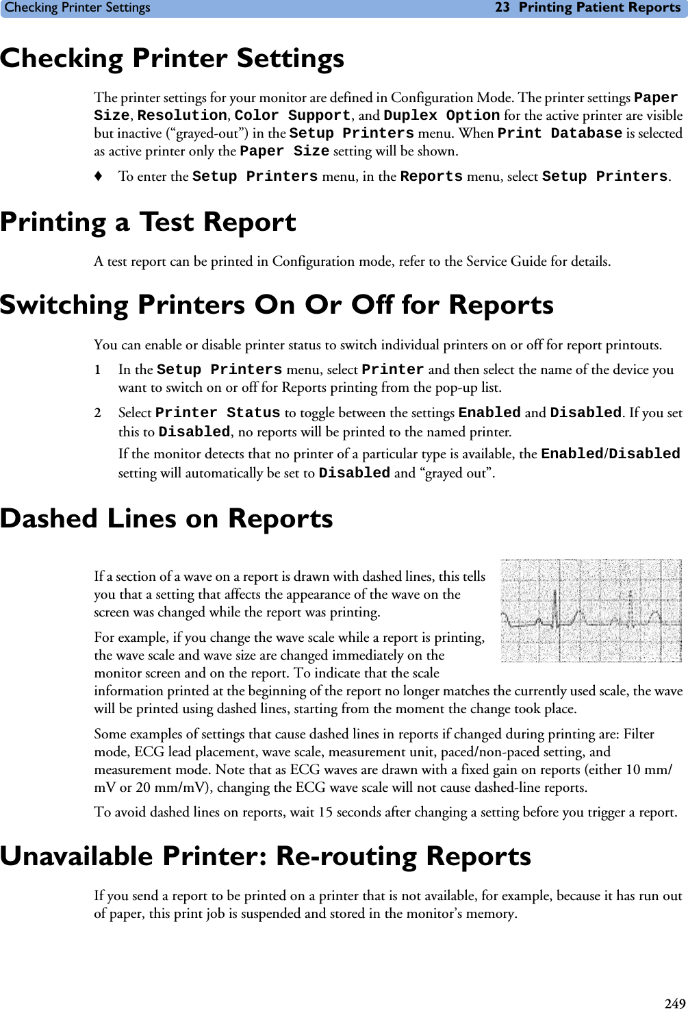
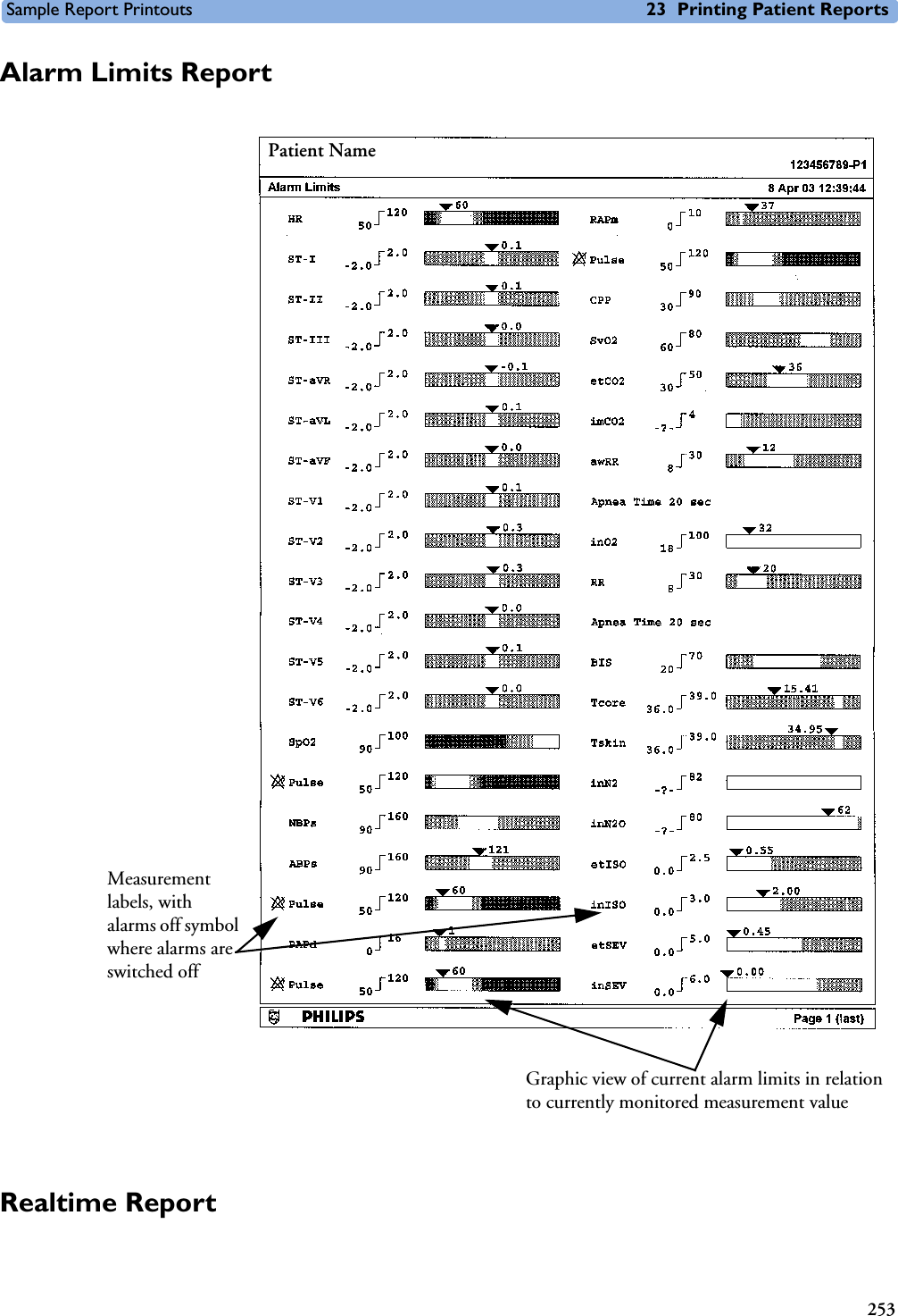
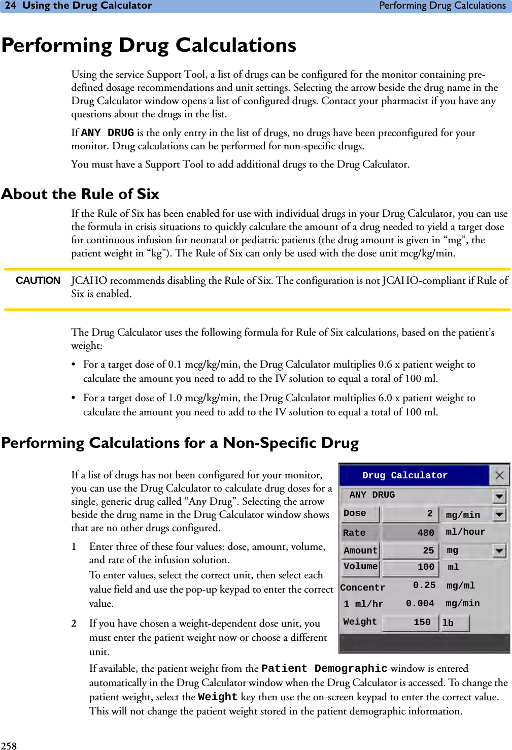
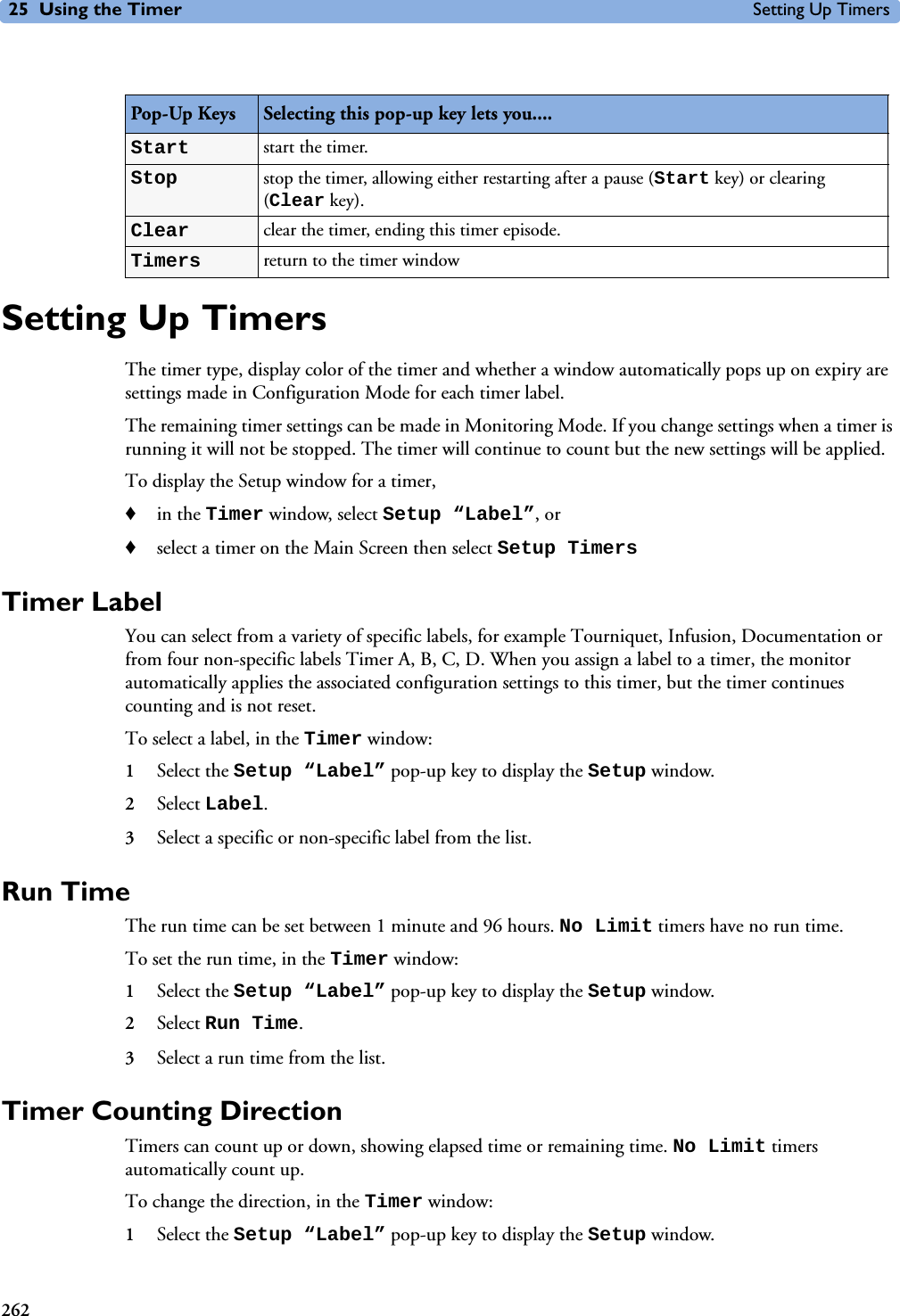
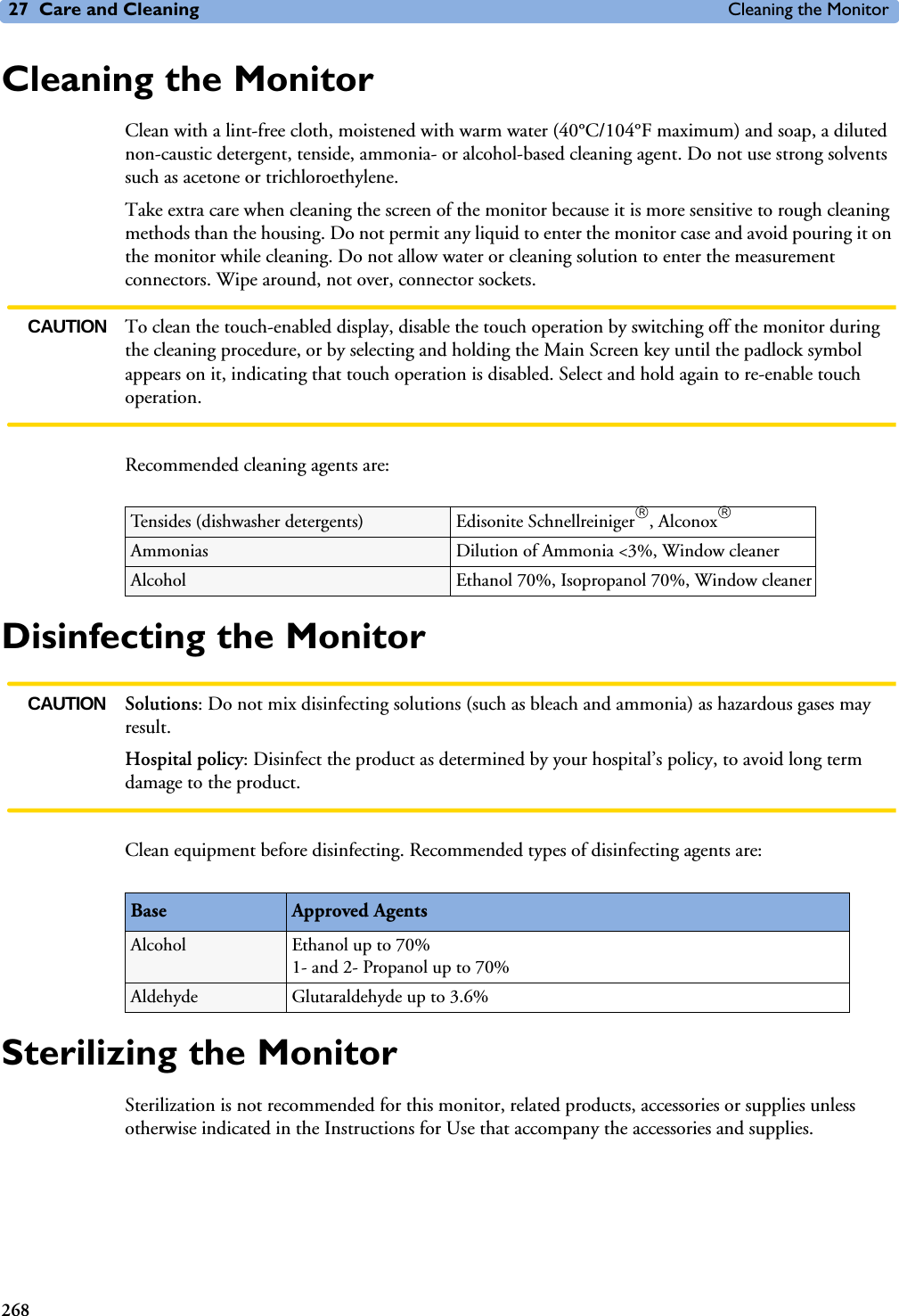
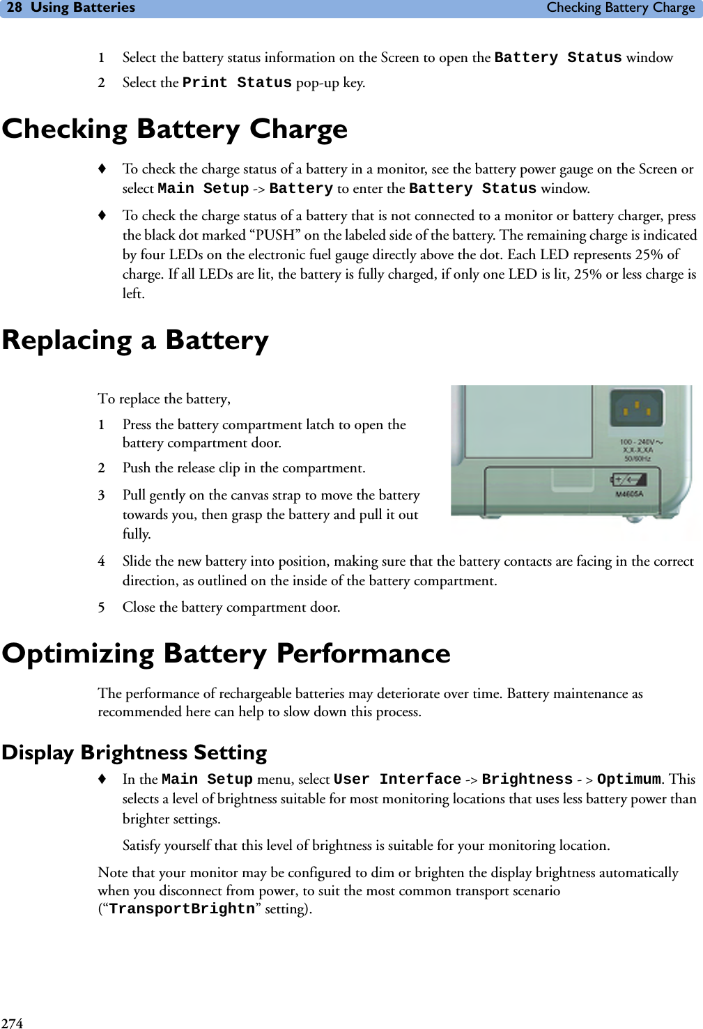
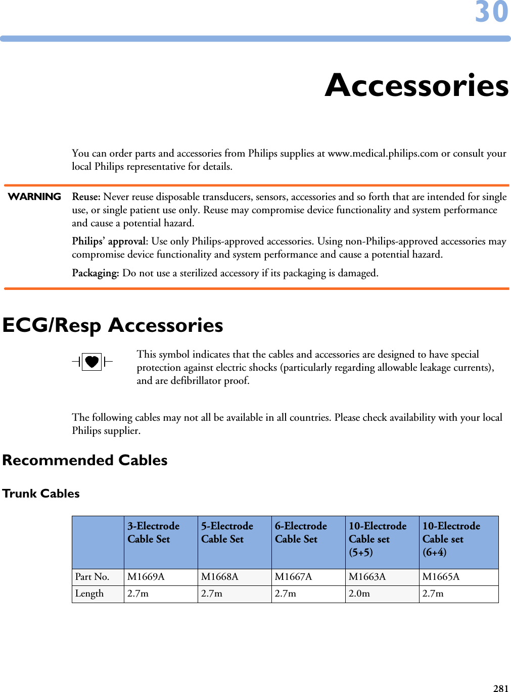
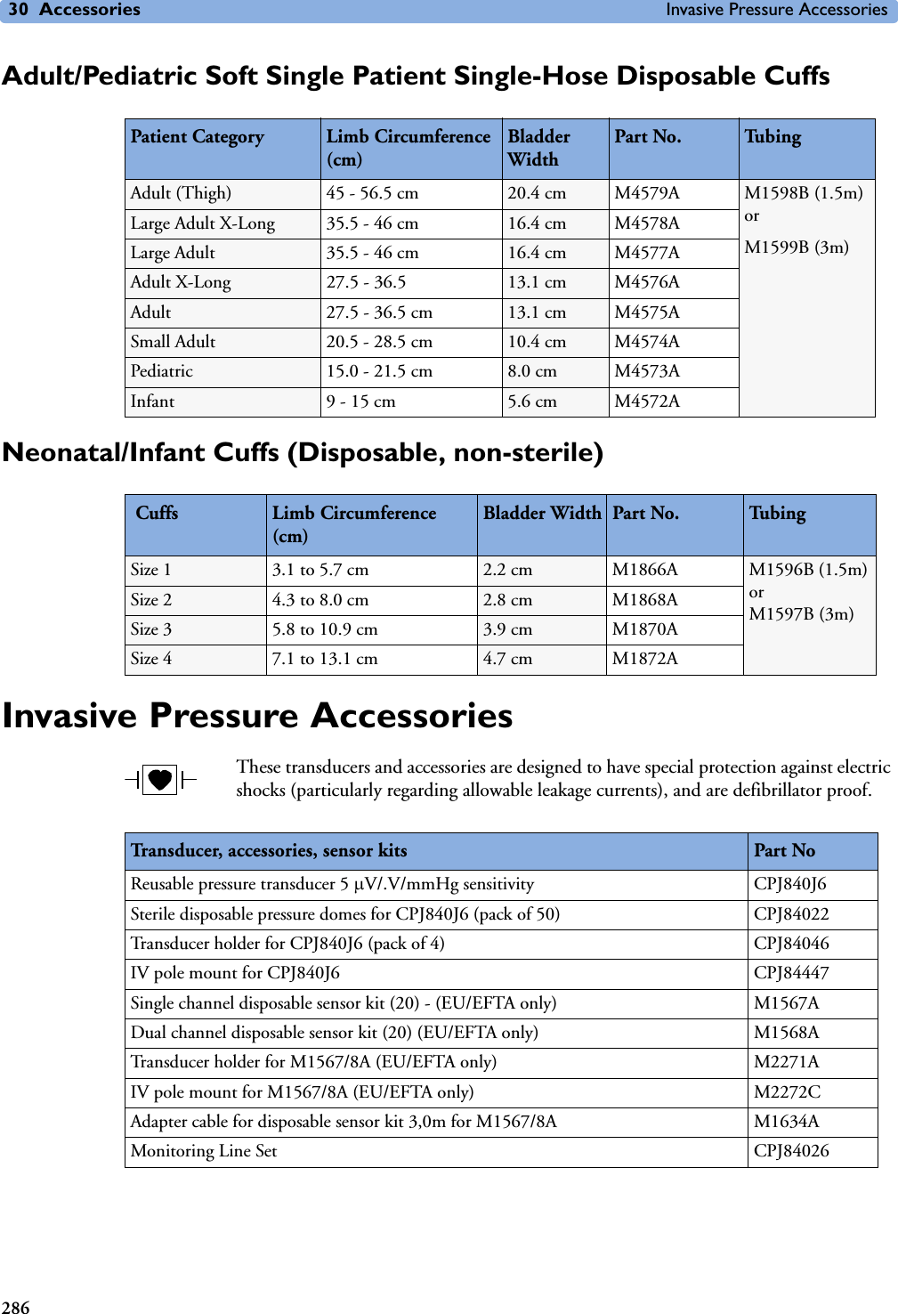
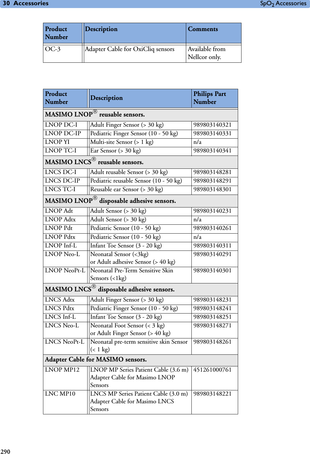
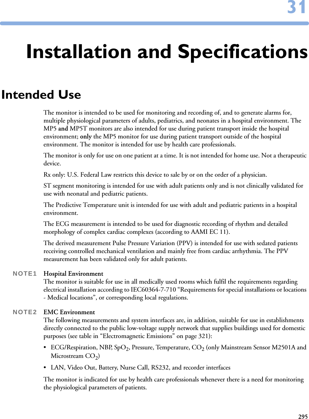
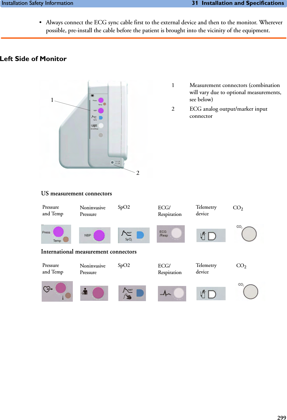
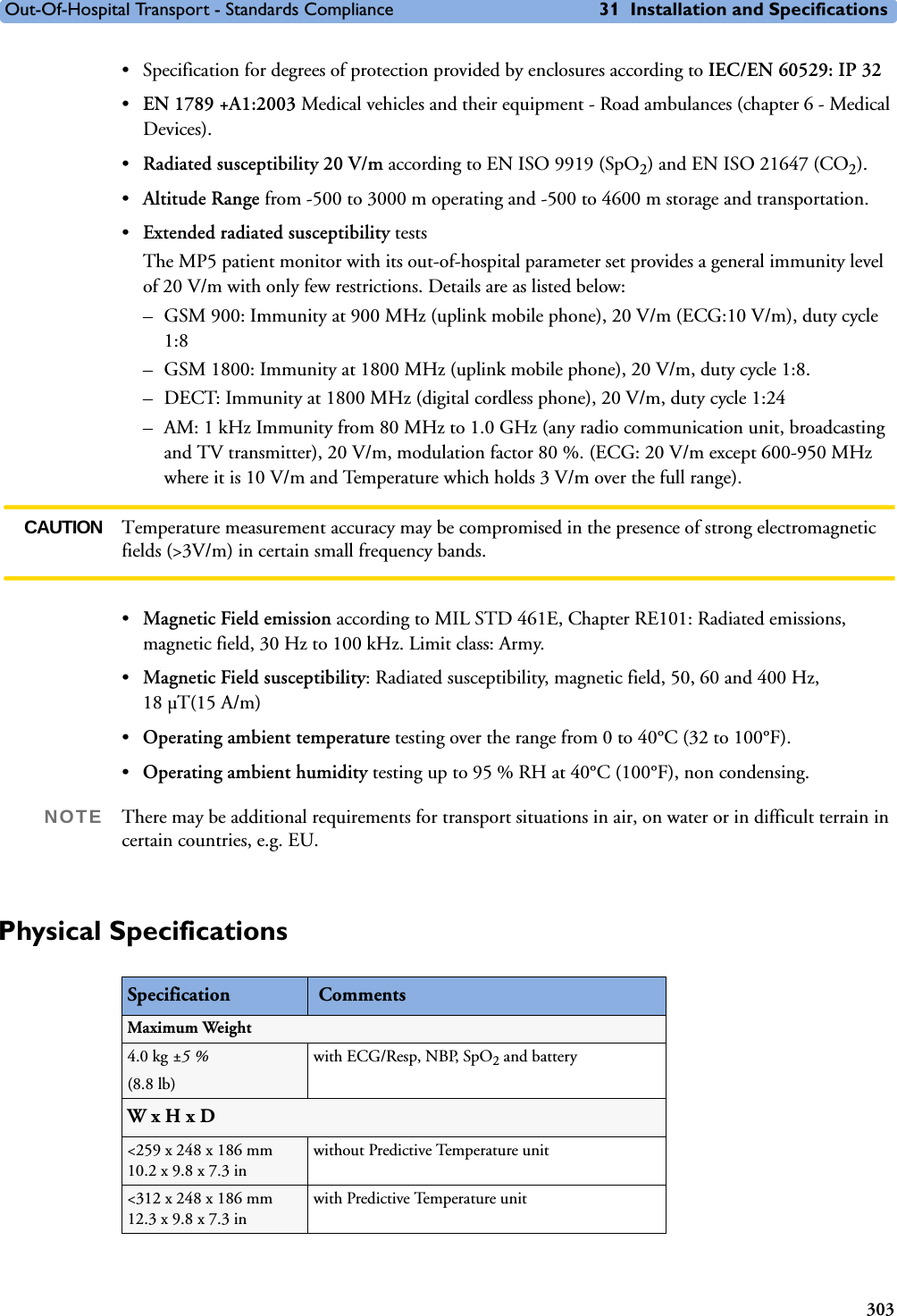
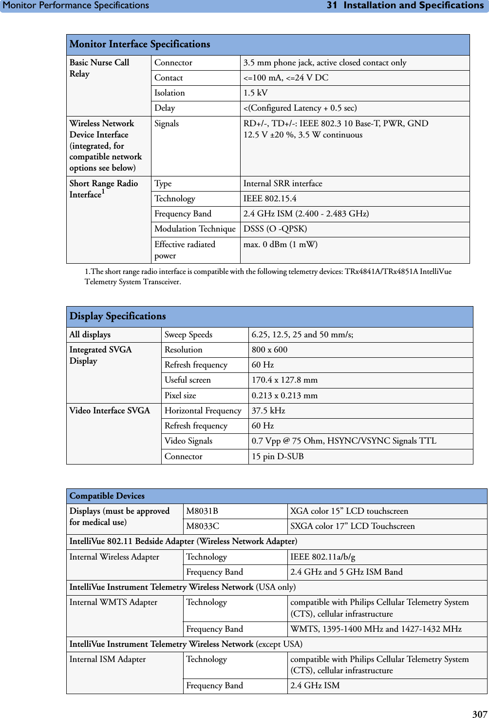
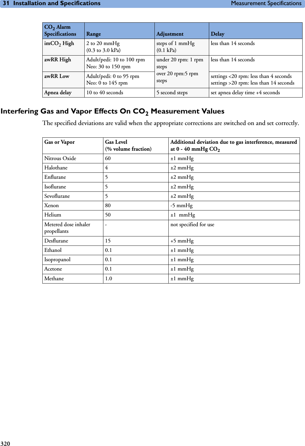
![5 Patient Alarms and INOPs Technical Alarm Messages (INOPs)70DEVICE CHECK CONF.INOP tone. IntelliBridge Device identification completed, but communication could not be established due to error. IntelliBridge INOP abbreviations may differ slightly depending on the device category.DEVICE DEMO DATAINOP toneIntelliBridge The device connected to the IntelliBridge module reports demo data but the monitor is not in DEMO mode.DEVICE REAL DATAINOP toneIntelliBridge The monitor is in DEMO mode but the device connected to the IntelliBridge module reports data that are not flagged as demo data. <Device> UNPLUGGEDINOP tone. IntelliBridge The IntelliBridge module has been unplugged from the rack, or the whole rack has been disconnected. Silencing this INOP switches off the measurement.IntelliBridge INOP abbreviations may differ slightly depending on the device category.DEVICE UNSUPPORTEDINOP tone. IntelliBridge Device identification completed, but no appropriate device driver installed.IntelliBridge INOP abbreviations may differ slightly depending on the device category.<EC10/EC40> EQUIP MALFINOP tone. IntelliBridge Malfunction in the IntelliBridge module. If this message appears repeatedly, the module must be replaced. Contact your service personnel.ECG/ARRH ALARM OFF!!ECG/AR ALARM OFFECG All ECG alarms have been switched off, or the HR alarm source is not ECG. To resume ECG alarm generation, switch ECG alarms on or select ECG as the alarm source. ECG EQUIP MALFNumeric is displayed with a -?- INOP tone. ECG Contact your service personnel.The ECG hardware is faulty.ECG EQUIP MALF TNumeric is displayed with a -?- INOP tone. Monitor Contact your service personnel.The ECG in the Telemetry device is faulty.(!!/!!!)<ECG LEAD> LEAD OFFNumeric is displayed with a -?-INOP tone. ECG Not all the required leads for ECG monitoring are connected. Check the ECG connections and make sure that the electrode indicated by <ECG lead> [RA, LA, LL, RL, V or C] electrodes is attached. In EASI mode, all 5 electrodes must be connected. ECG EL. NOISY <ECG LEAD> ECG The ECG signal from the named ECG electrodes [RA, LA, LL, RL, V (or C)] is noisy. Check the ECG connections and make sure that the electrode indicated is attached.(!!/!!!)ECG LEADS OFF ECG Check that all of the required ECG leads are attached, and that none of the electrodes have been displaced.ECG NOISY SIGNALINOP tone. ECG The ECG signal is too noisy. Check that the electrodes are properly placed and have not dried out. Remove any possible sources of signal noise (such as power cords) from the area around the cable and the patient.The ECG signal may be saturated or overloaded.EcgOut EQUIP MALFINOP toneECG Check that the ECG out cable is securely connected. Contact your service personnel.EEG EQUIP MALFINOP toneEEG The EEG hardware is faulty. Contact your service personnel.INOP Message, Indication Source What to do](https://usermanual.wiki/Philips-Medical-Systems-North-America/SRRBV1.User-Manual-MP5-and-MP5T/User-Guide-1044633-Page-80.png)
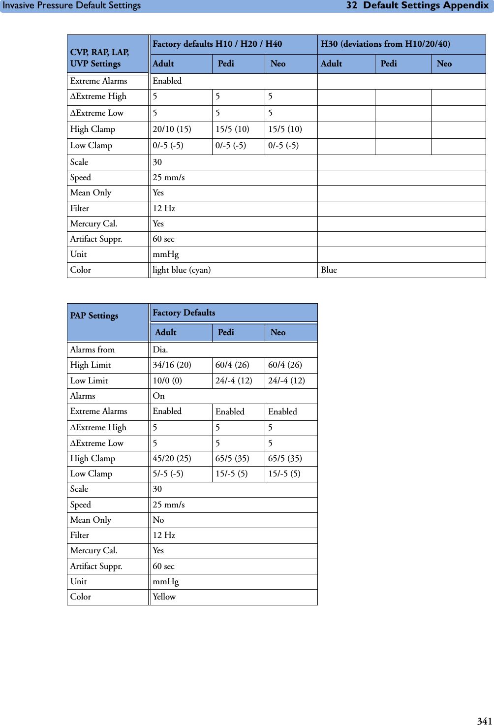
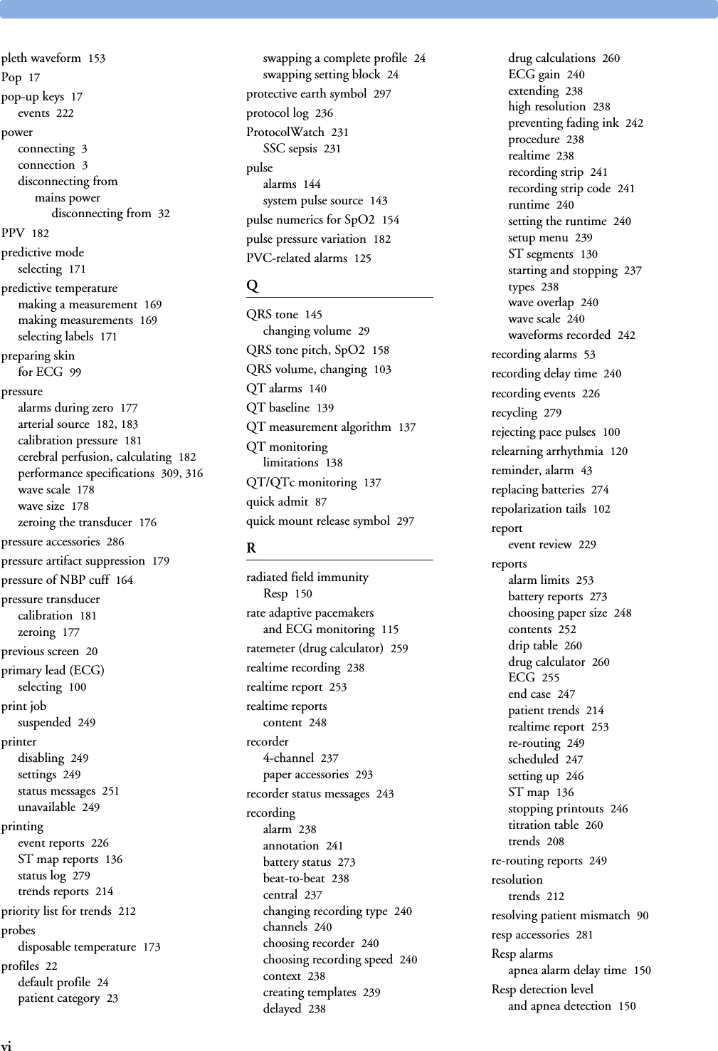
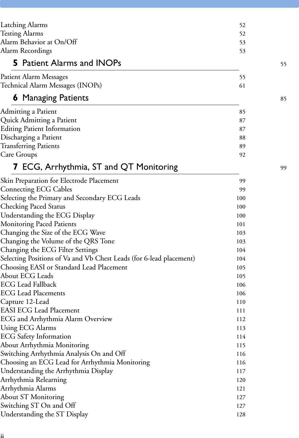
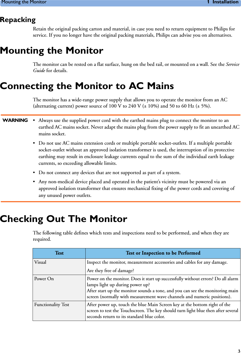
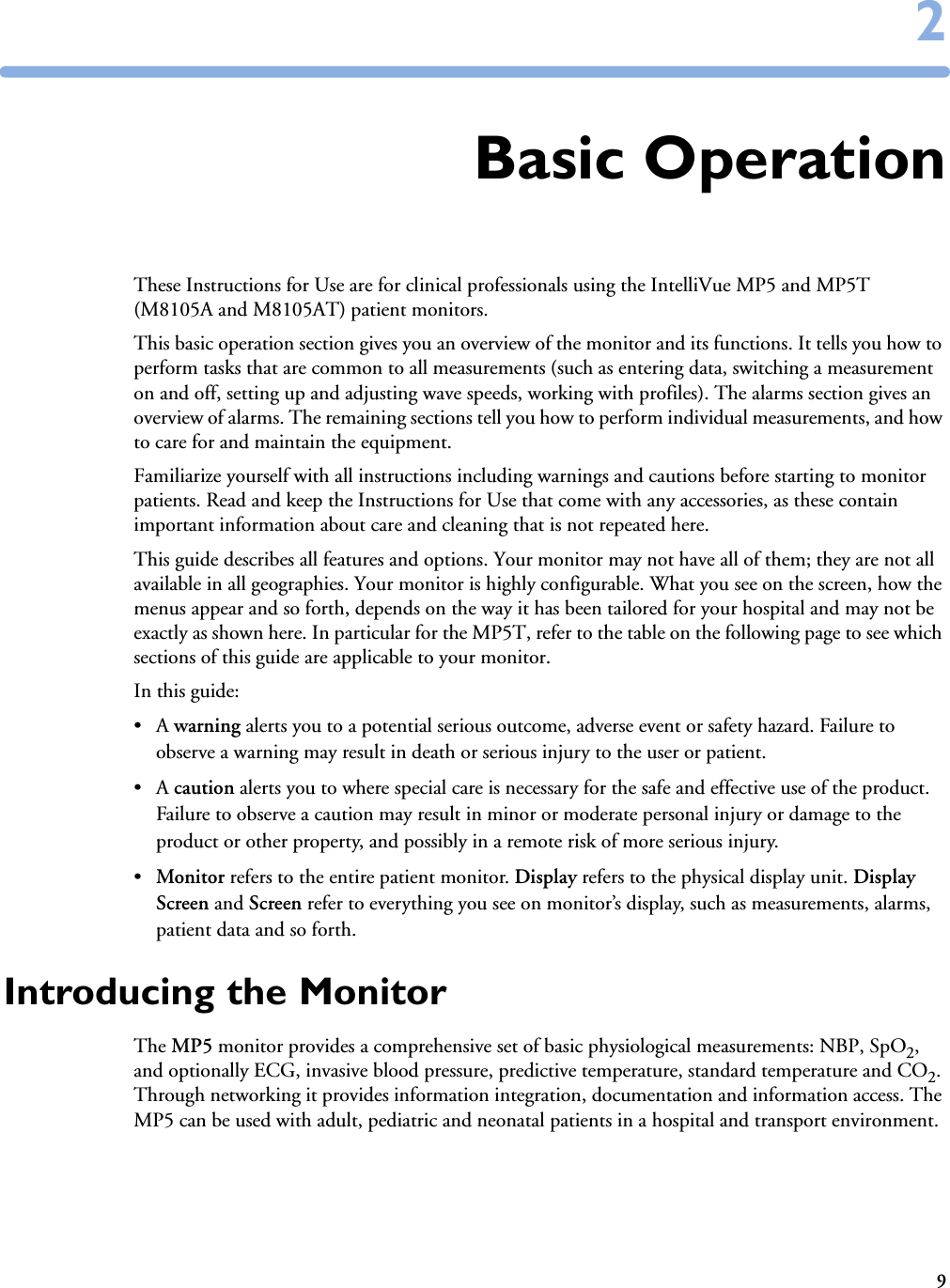
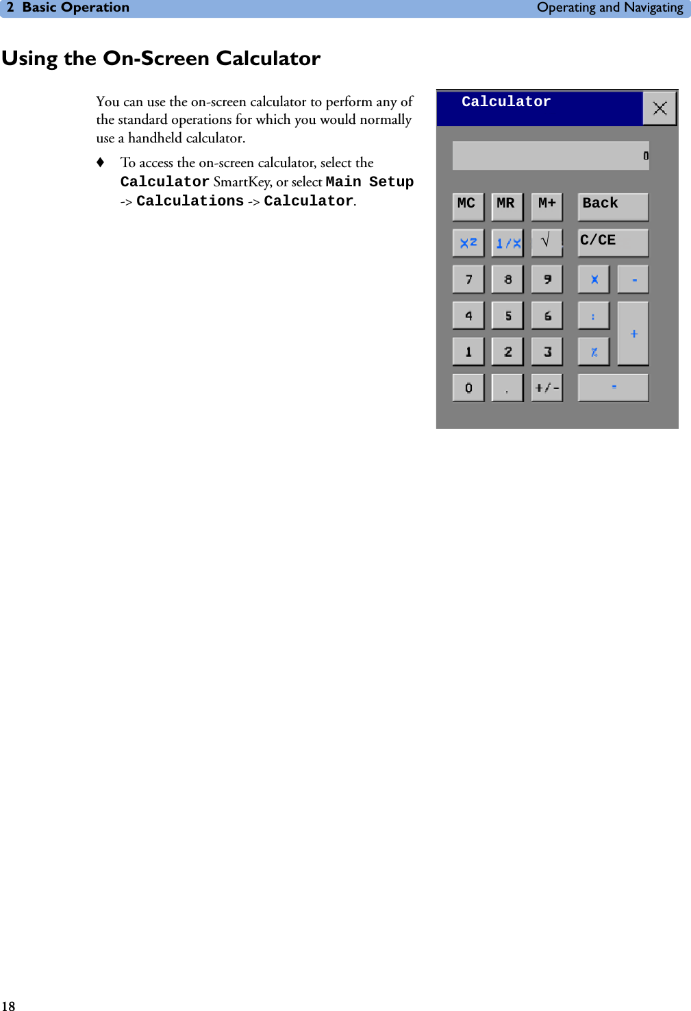
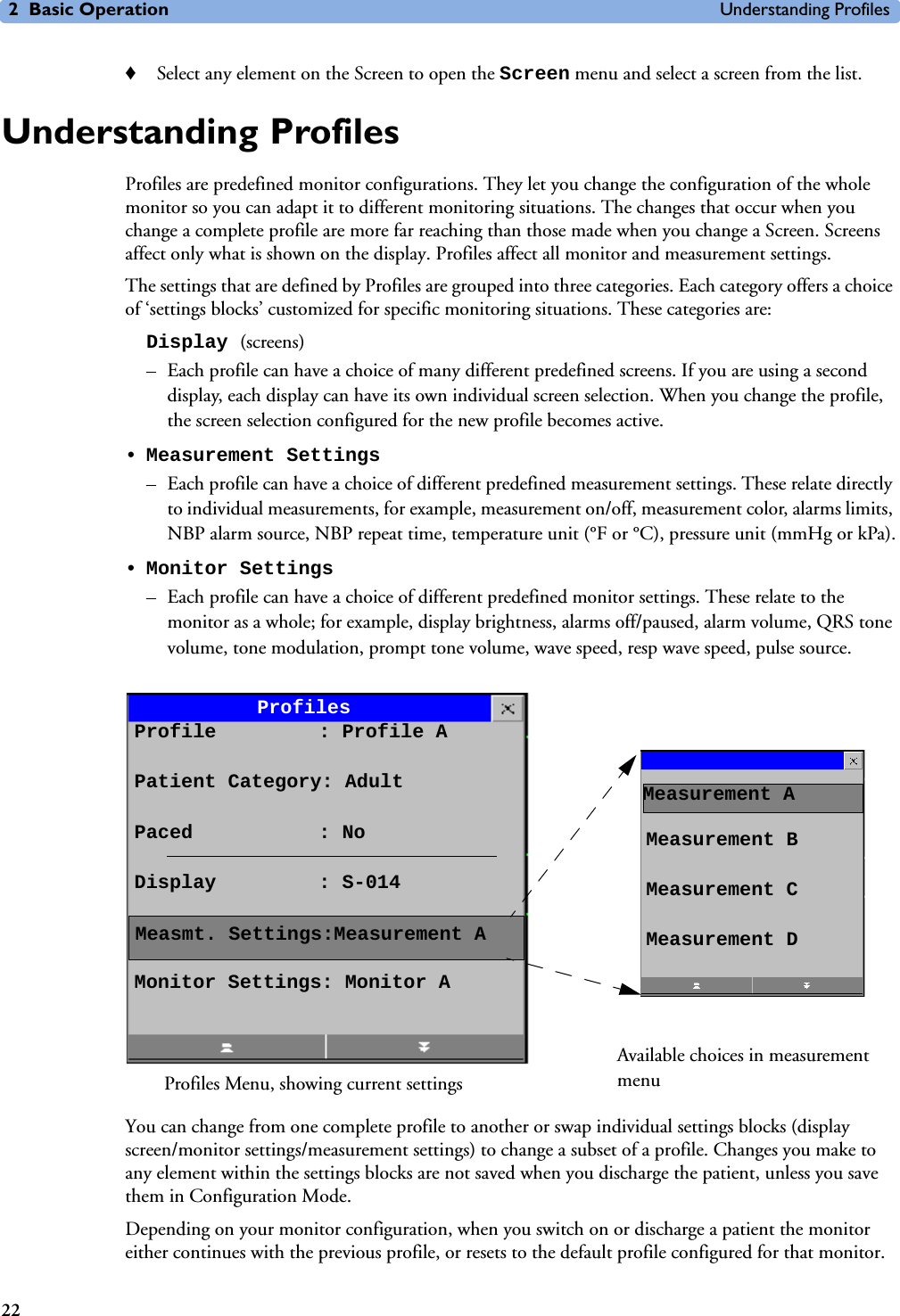
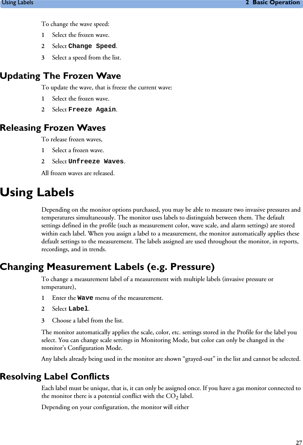
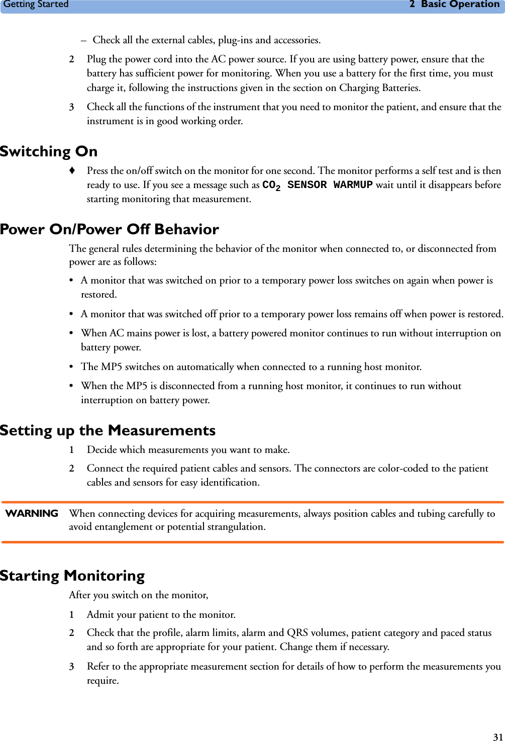
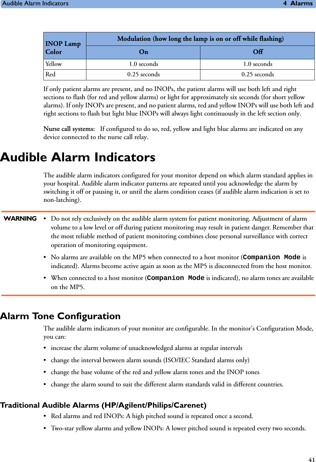
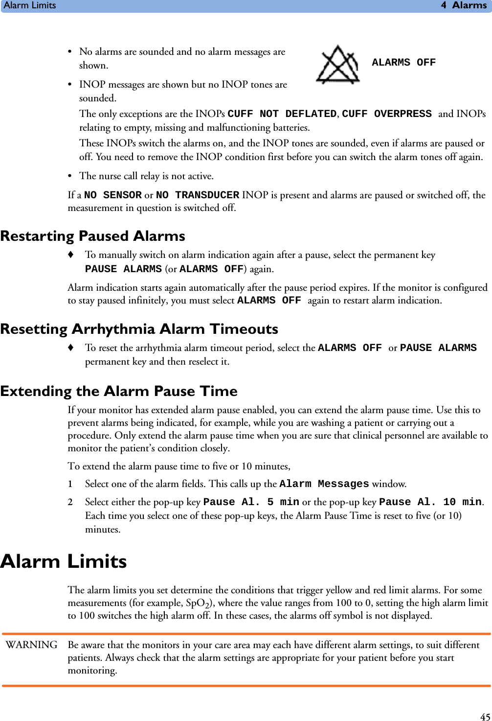
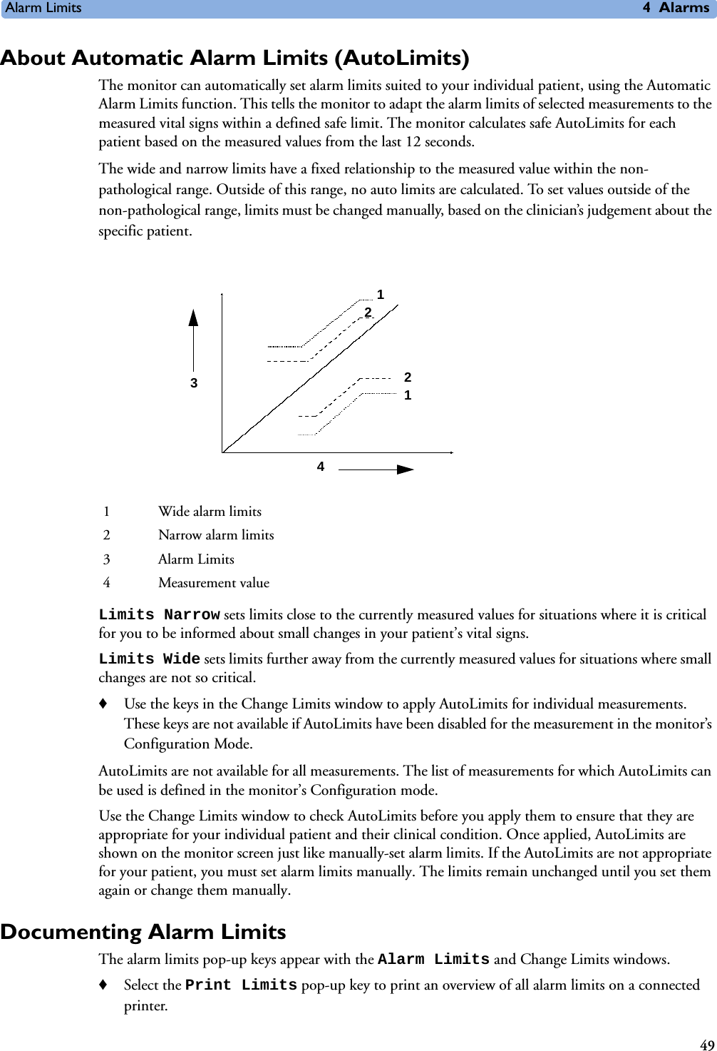
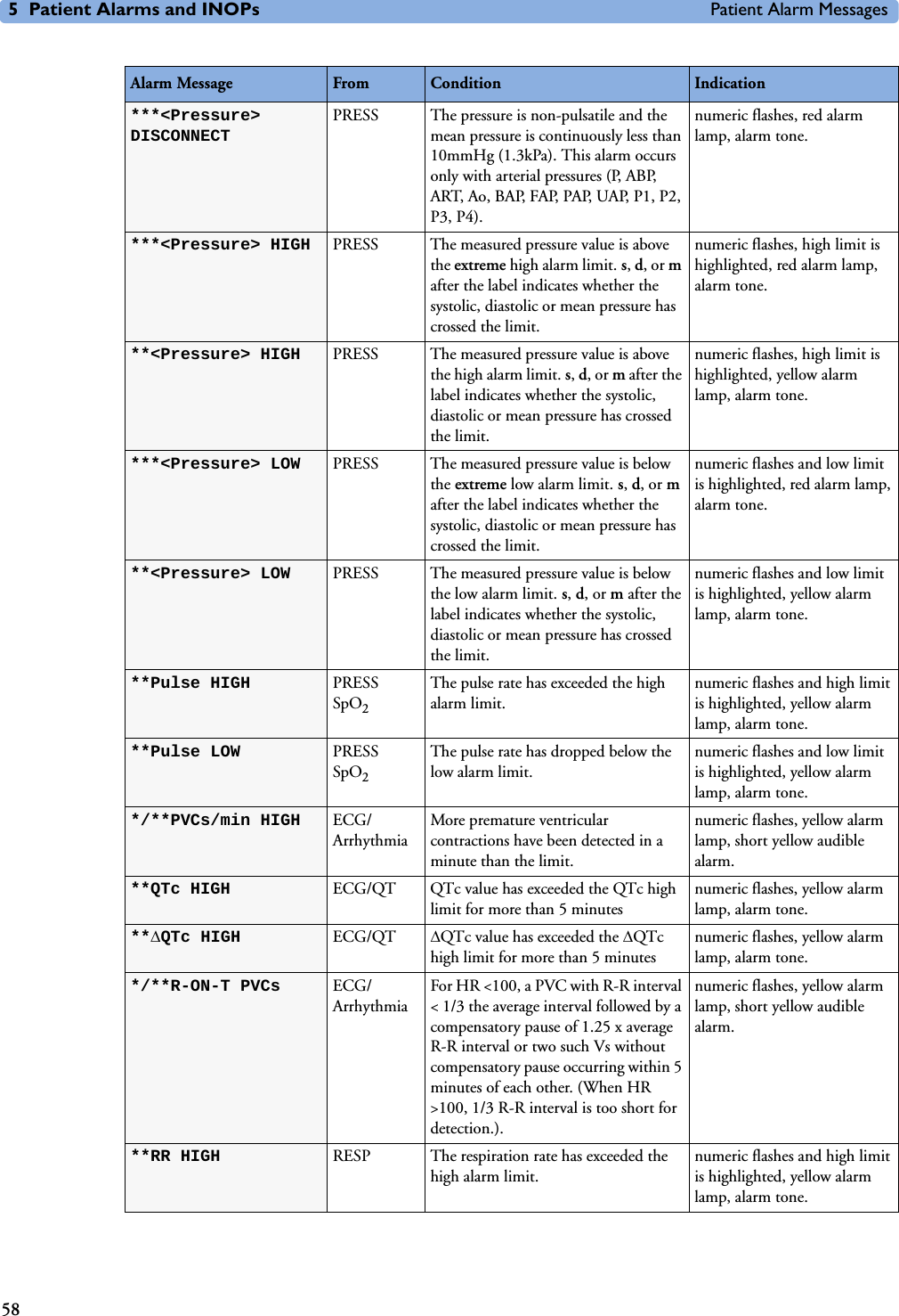
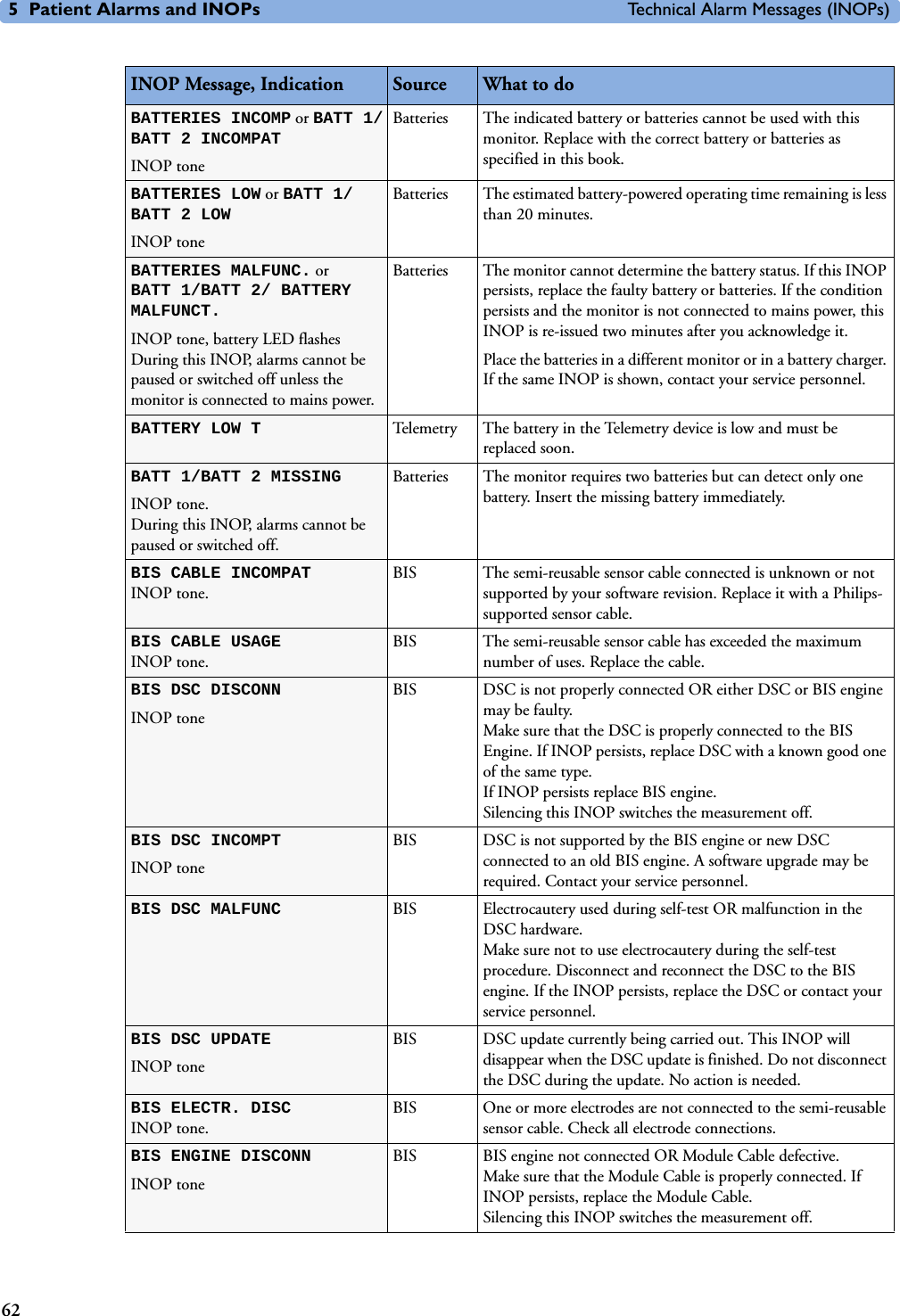
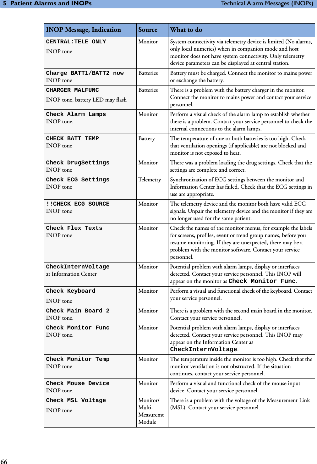
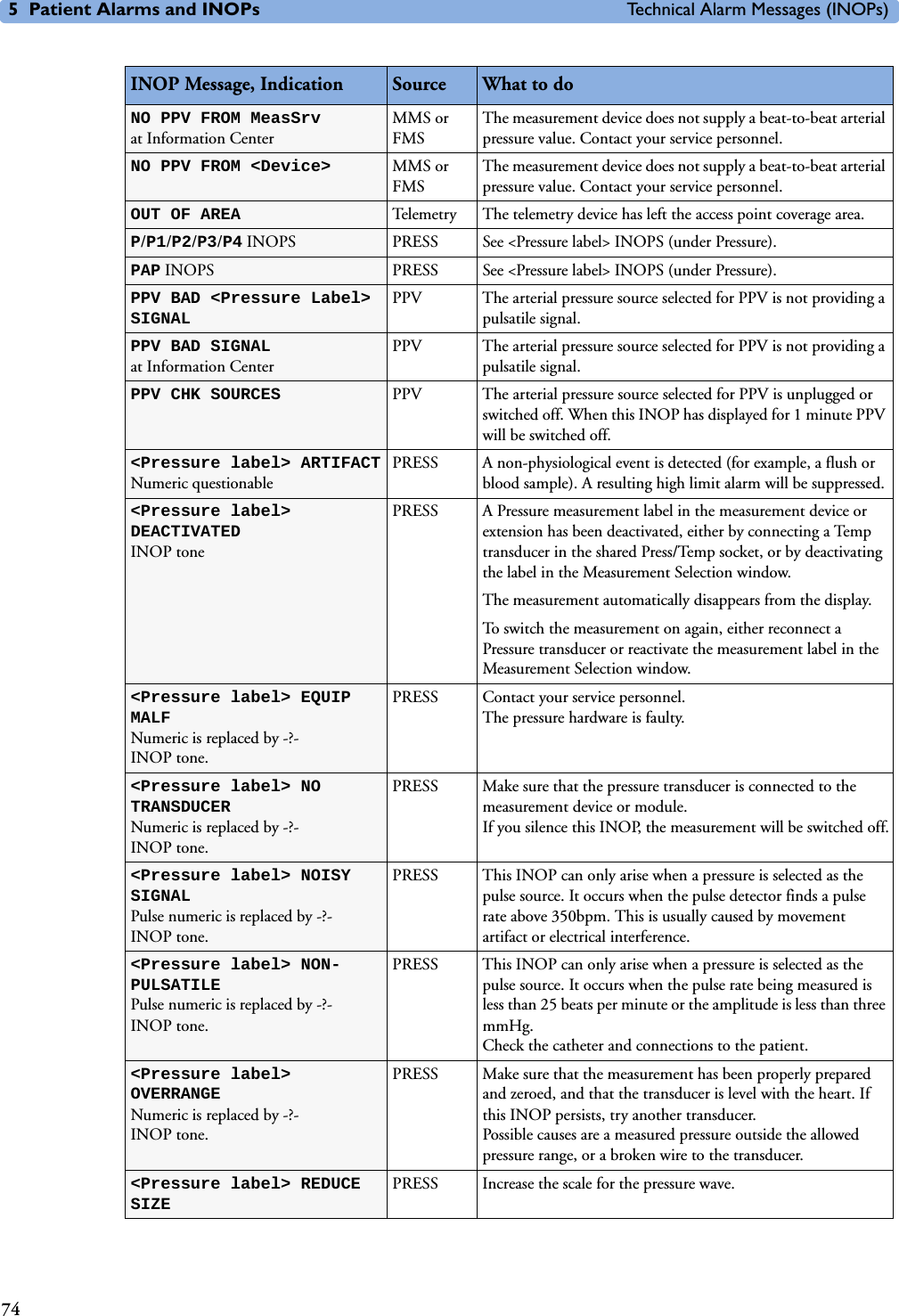
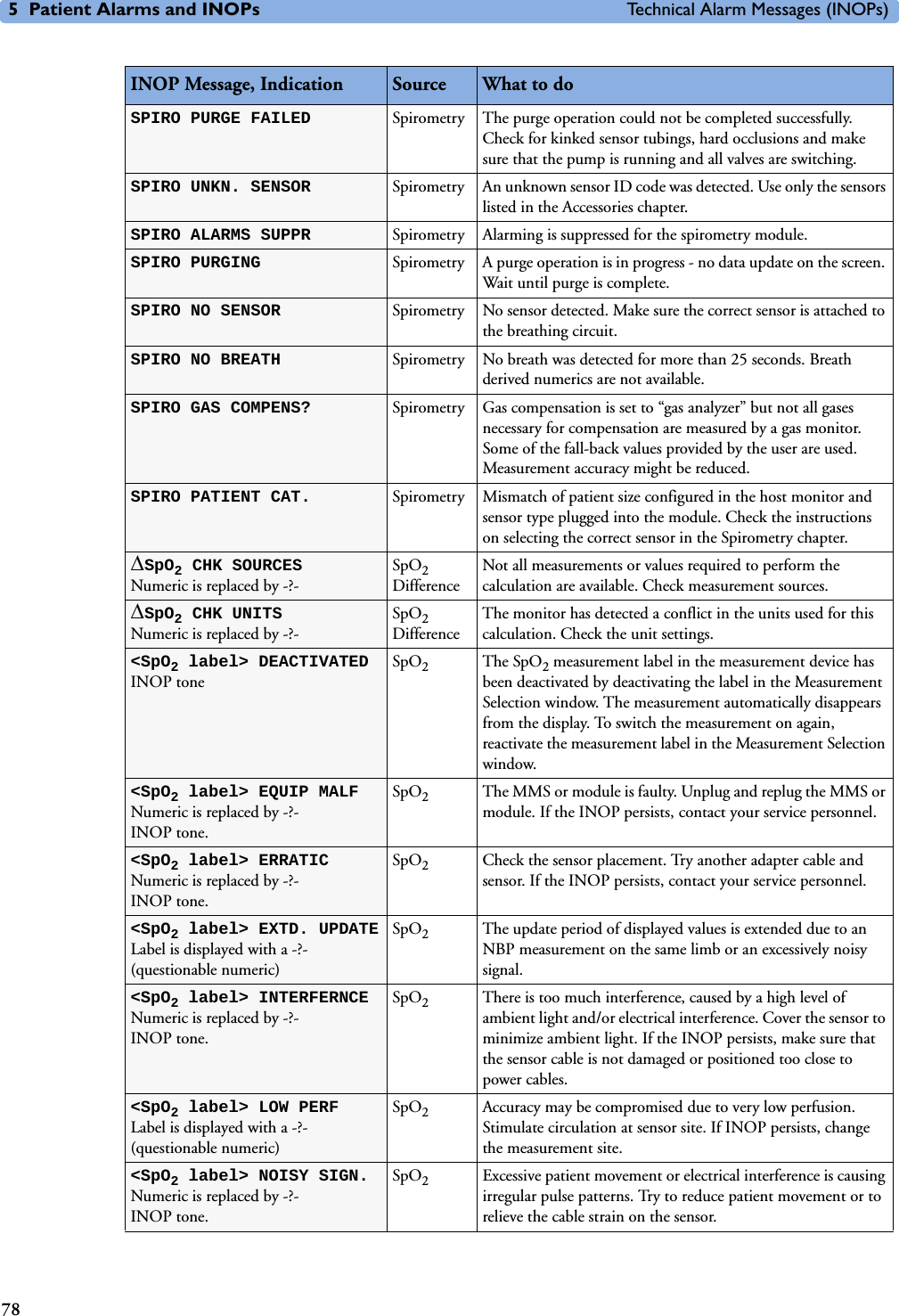
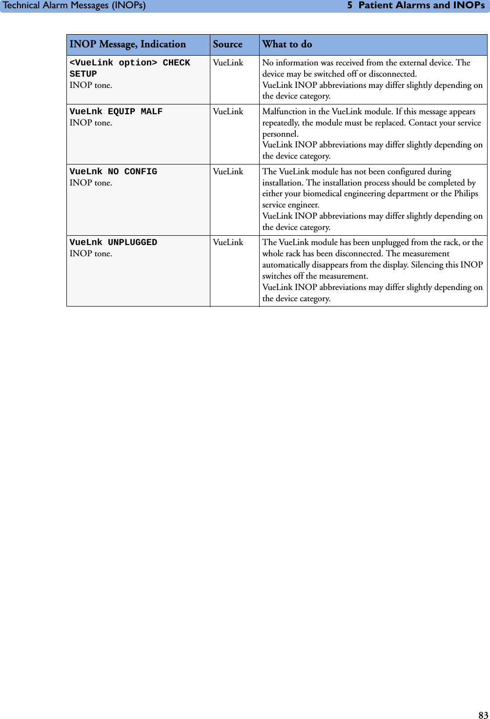
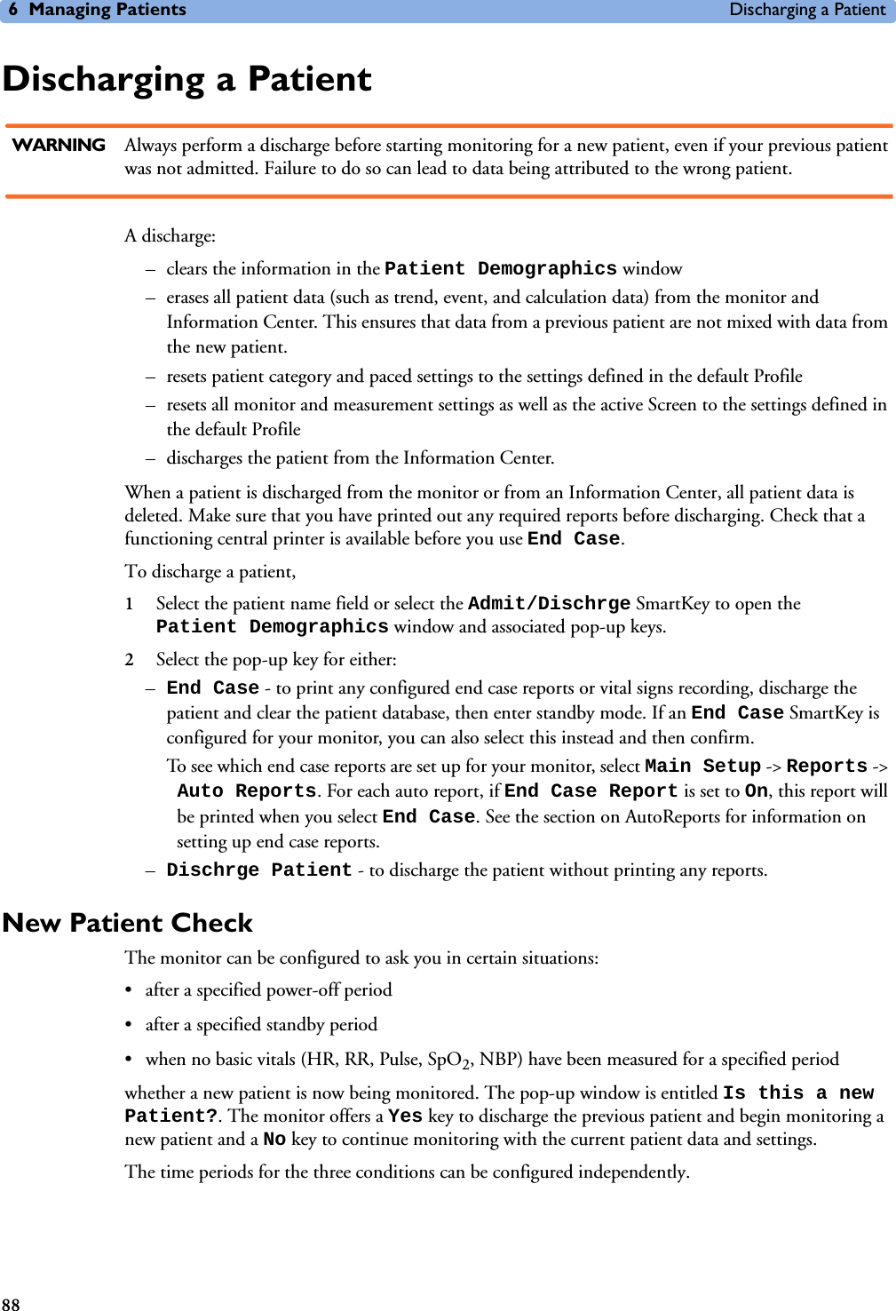
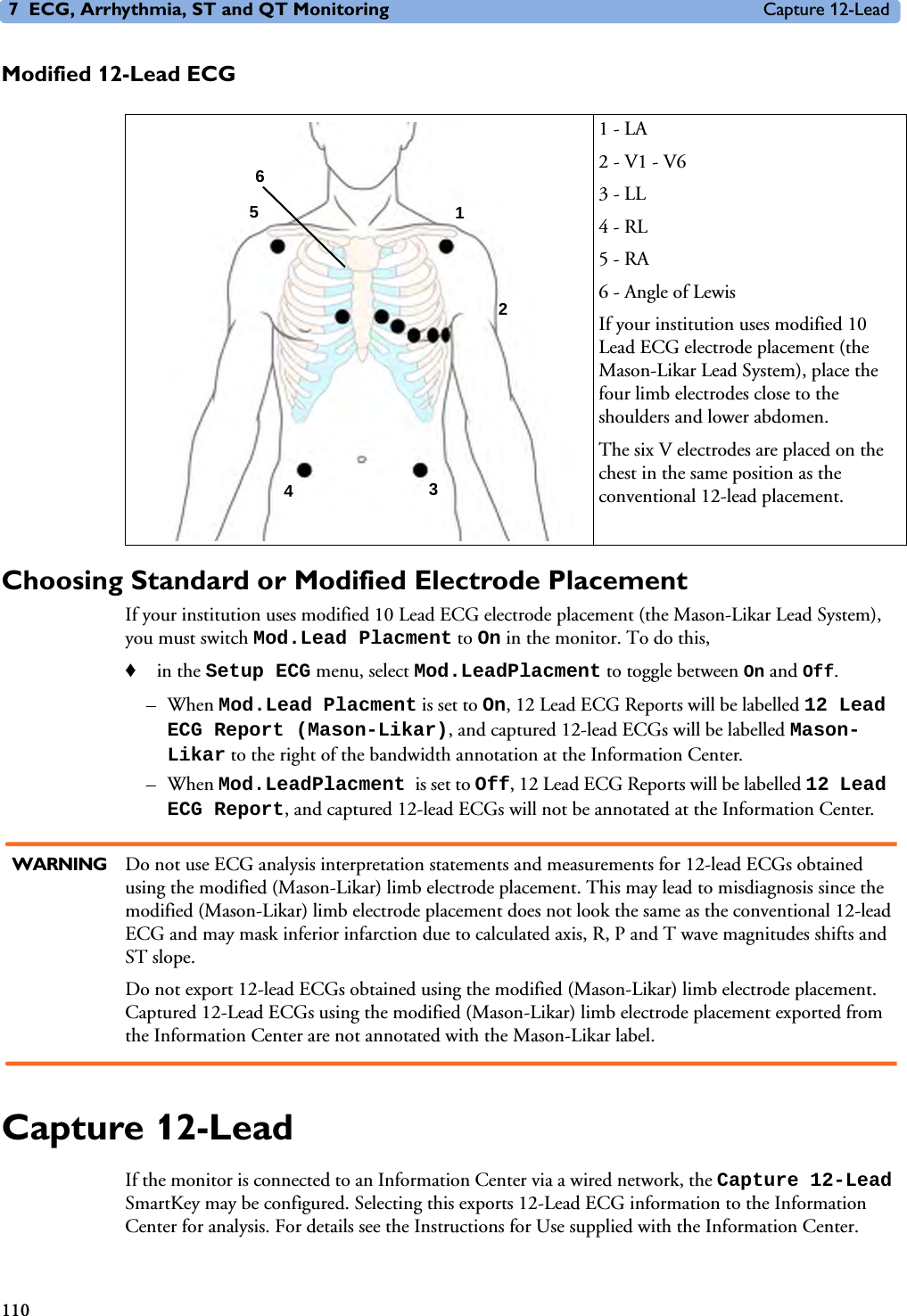
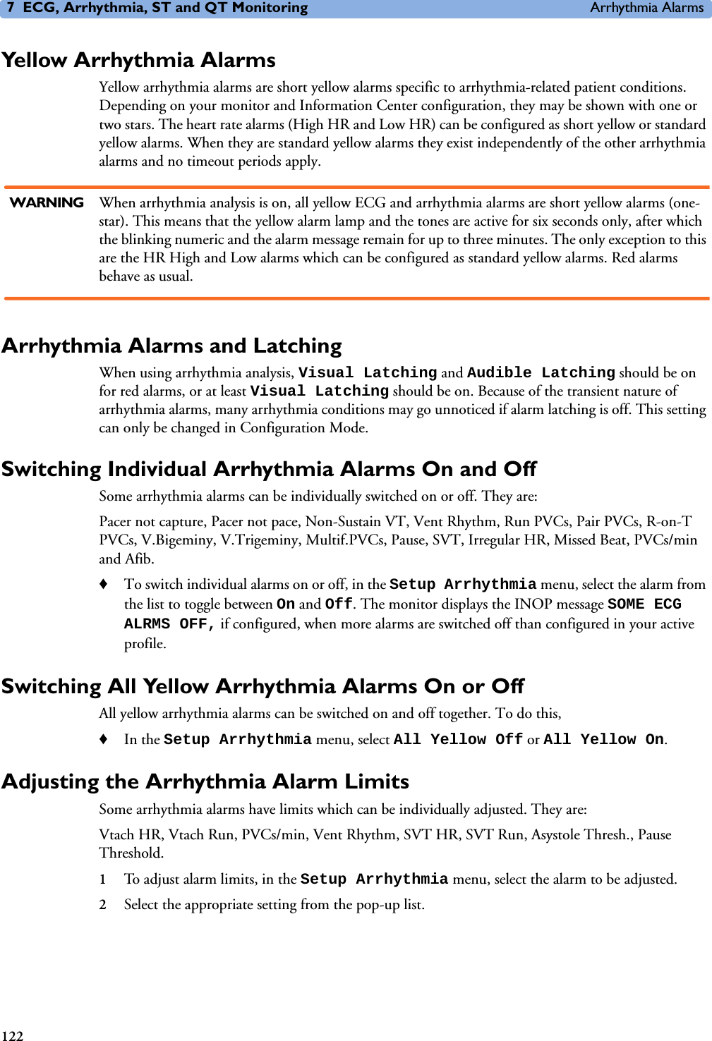
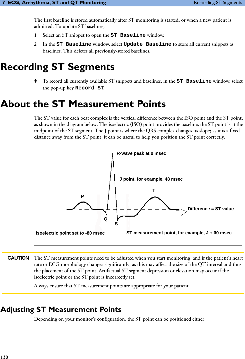
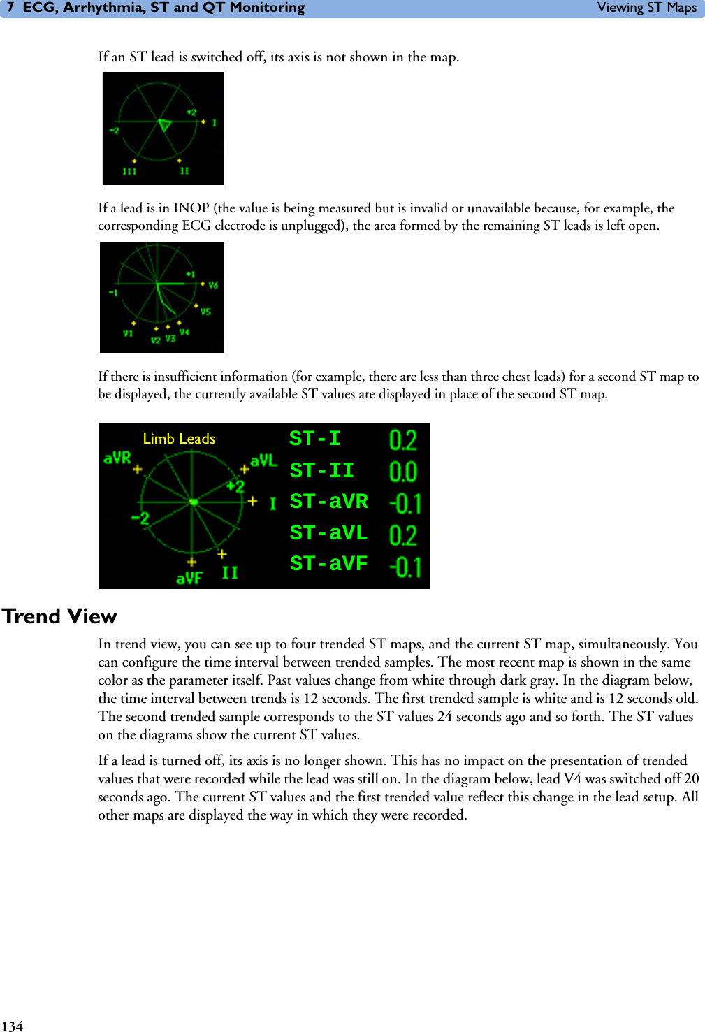
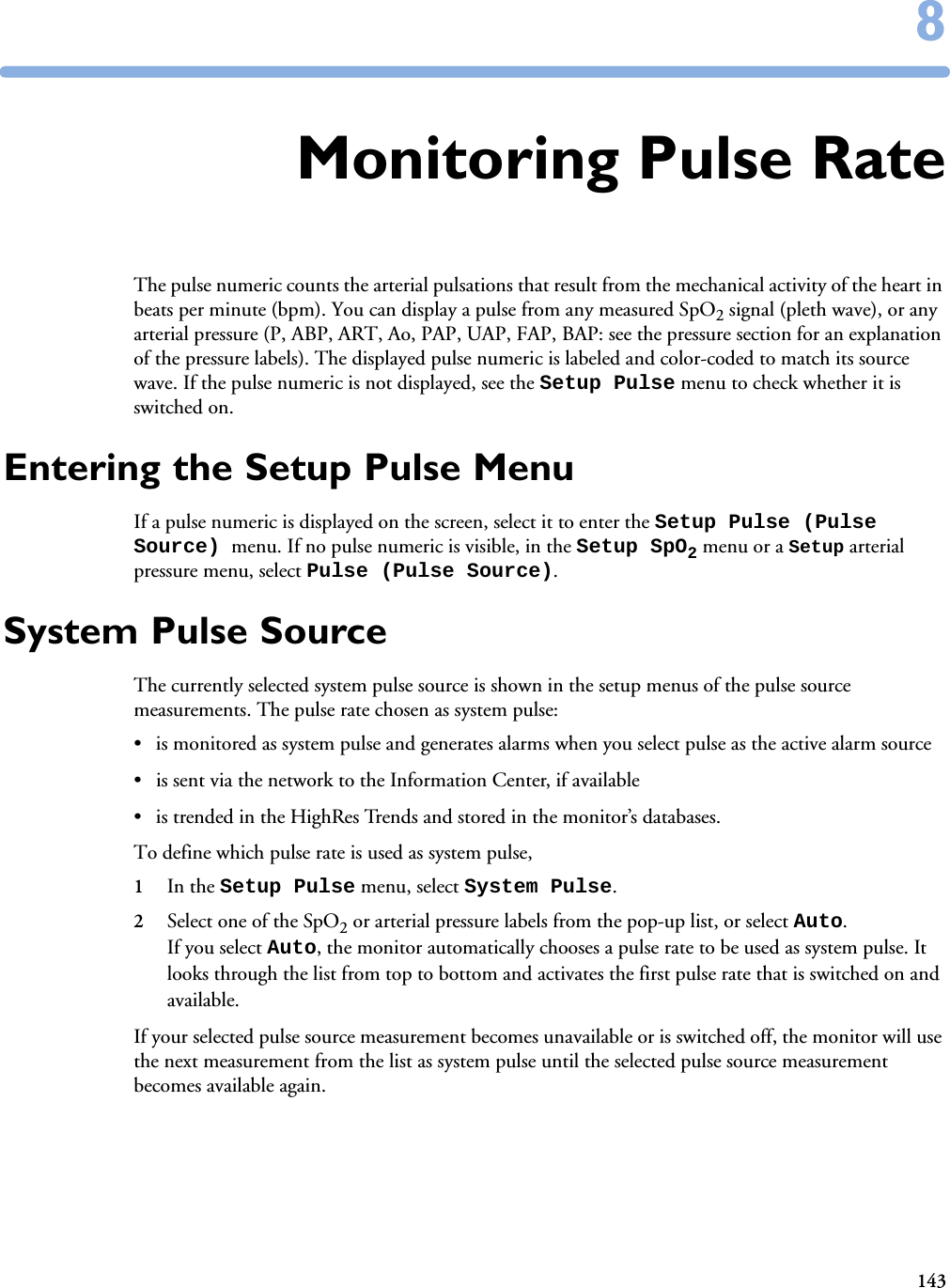
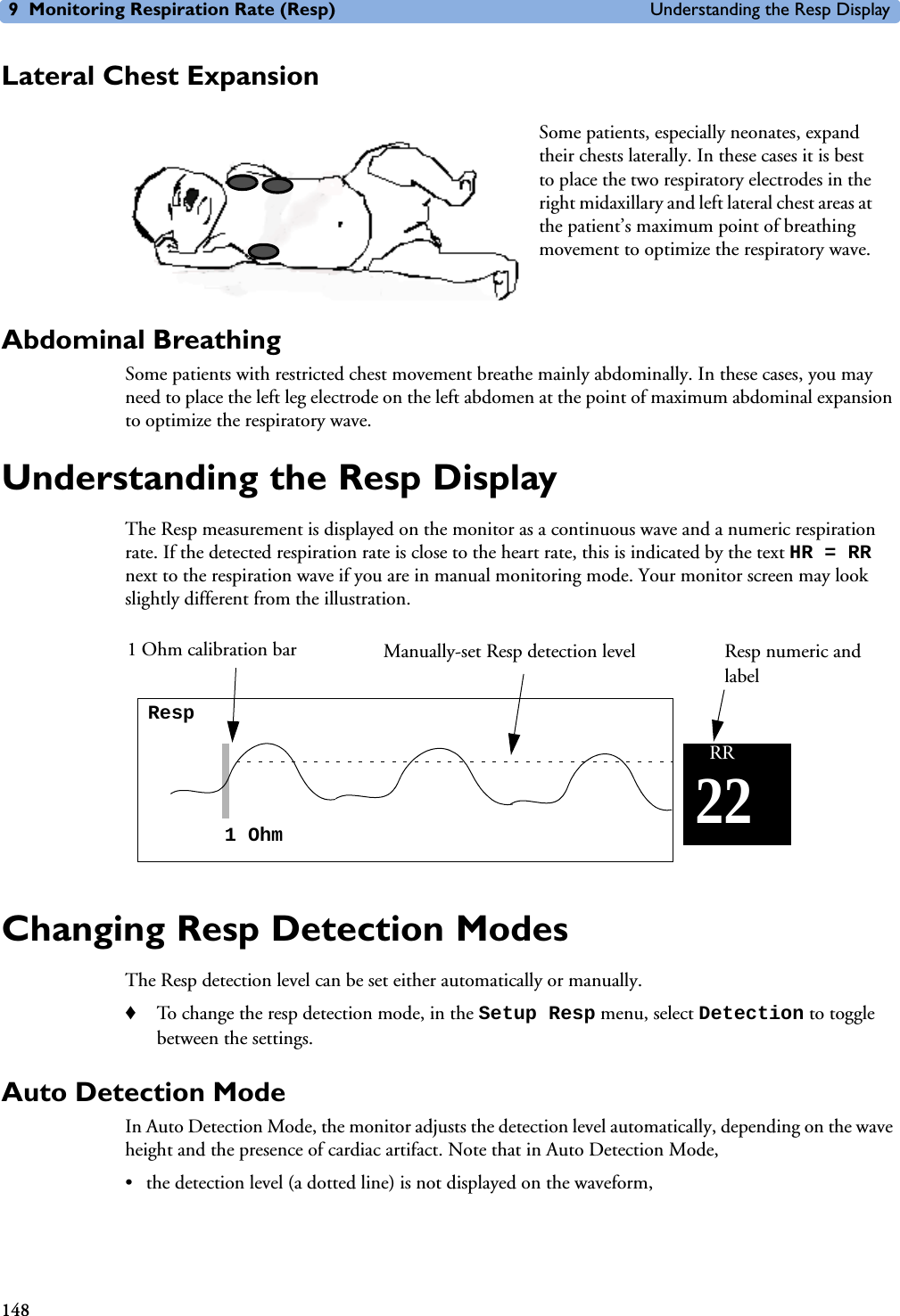
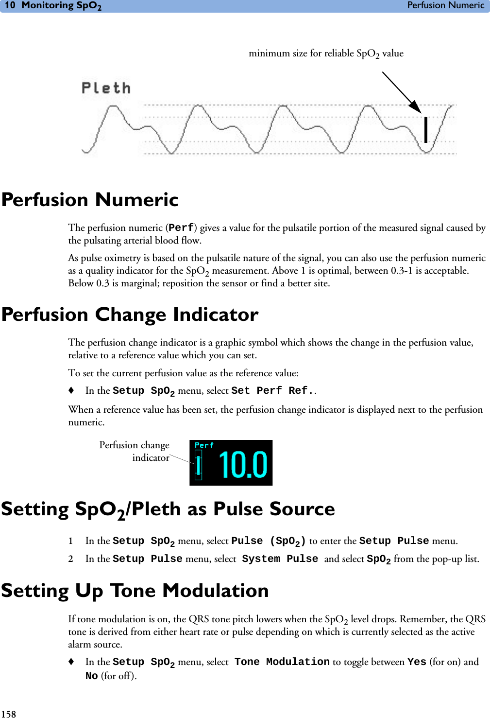
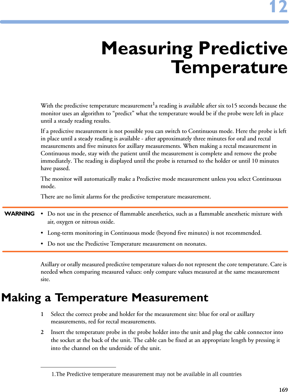
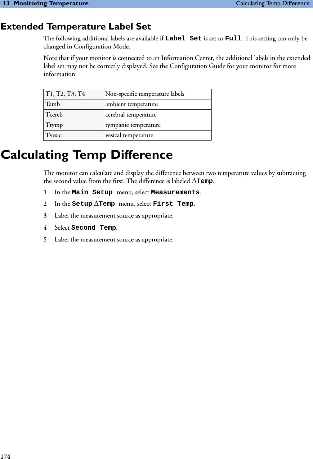
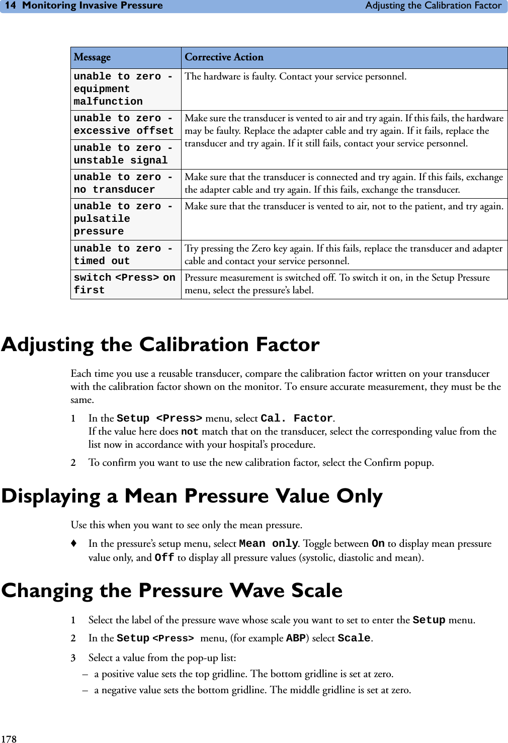
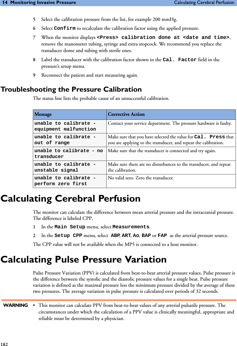
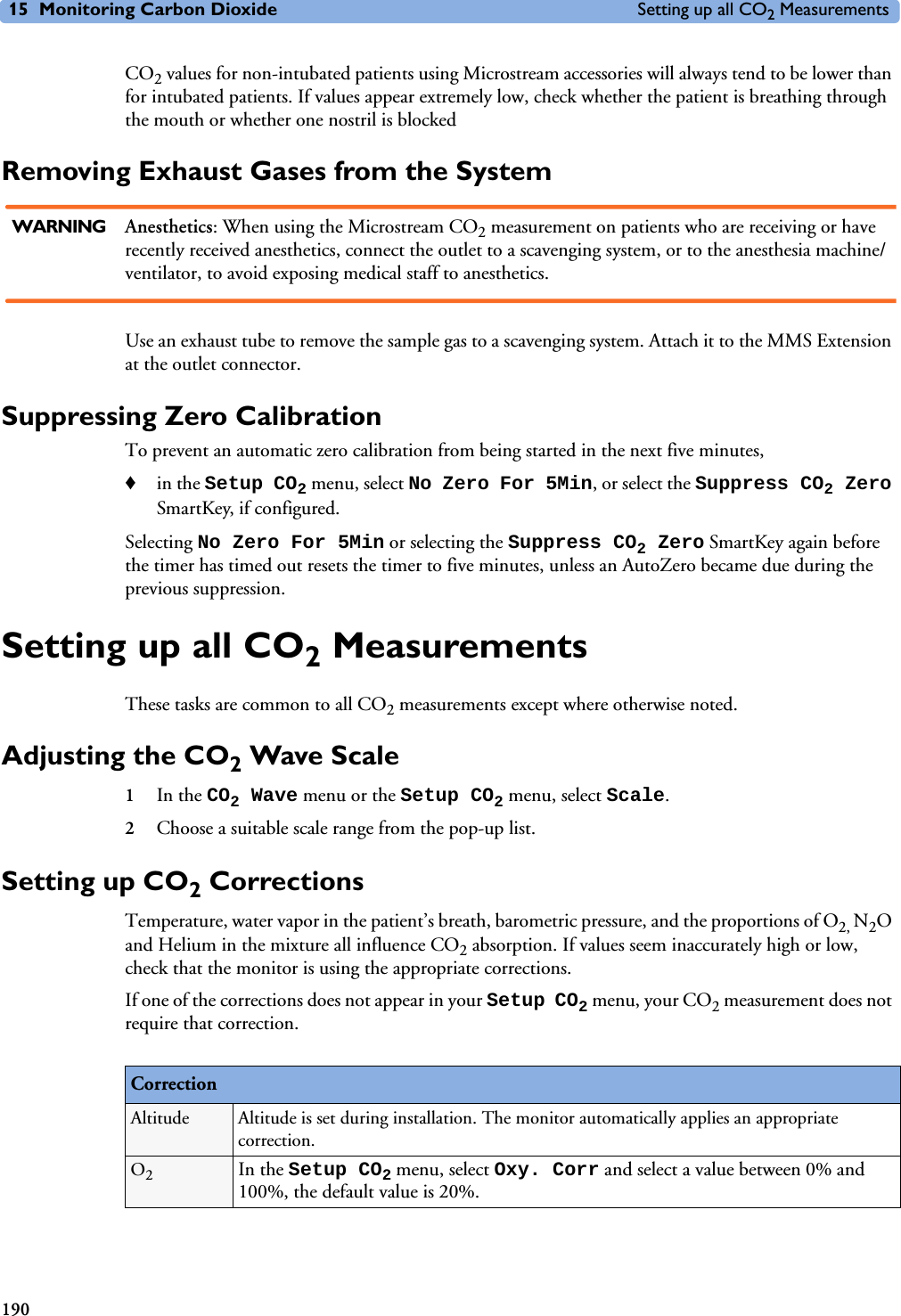
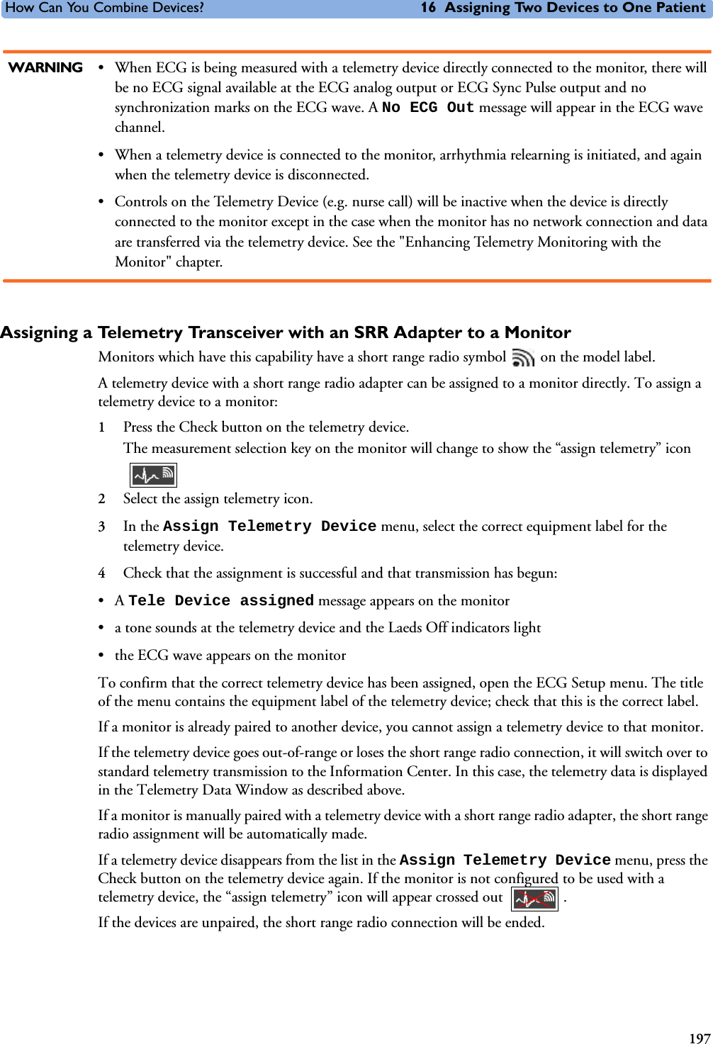
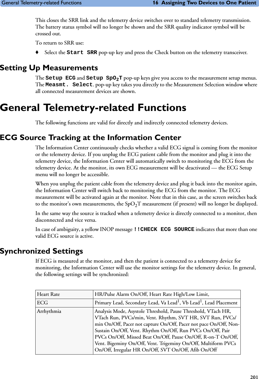
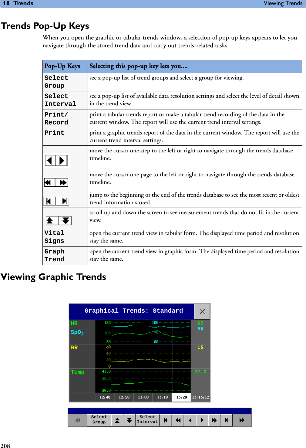
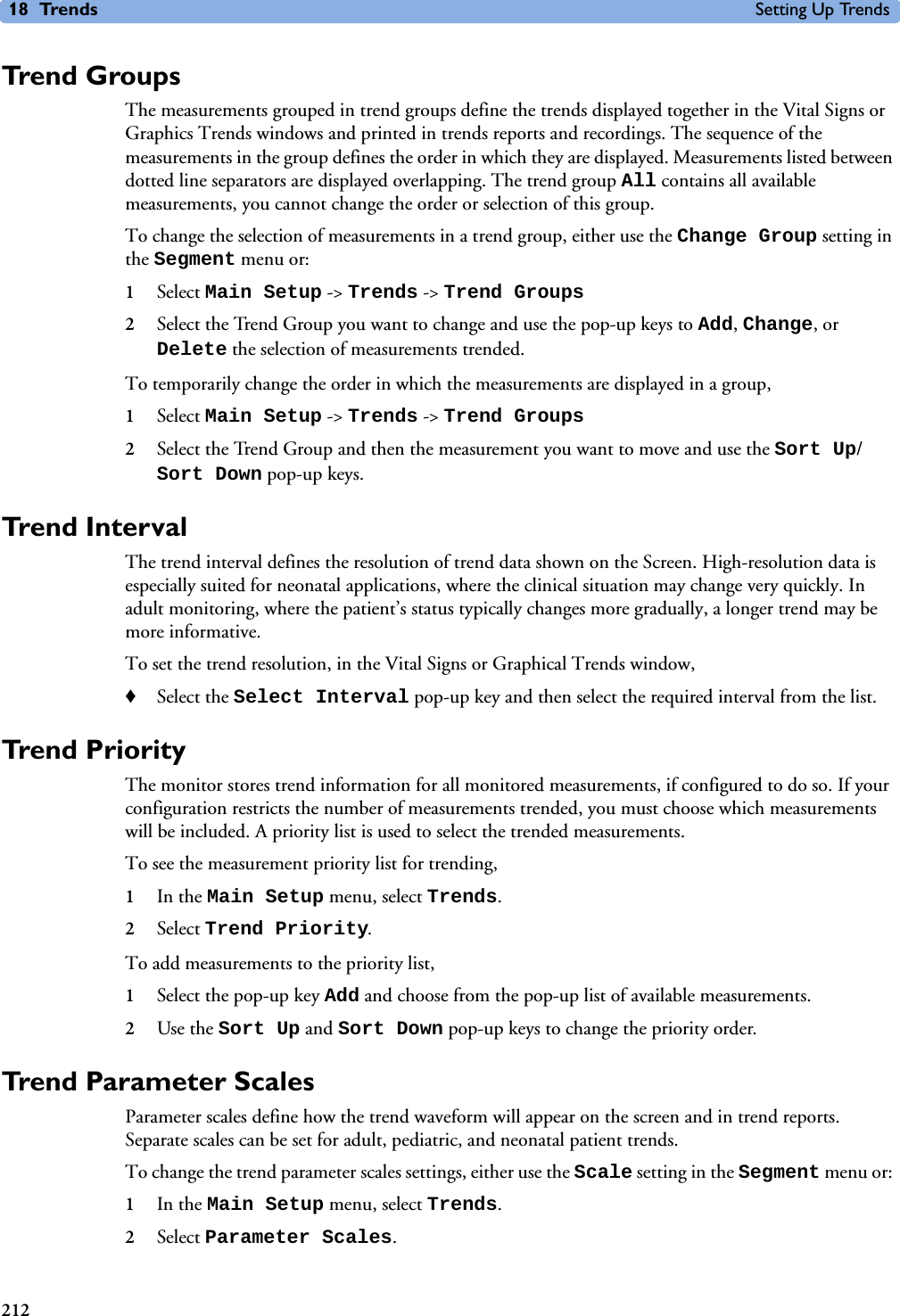
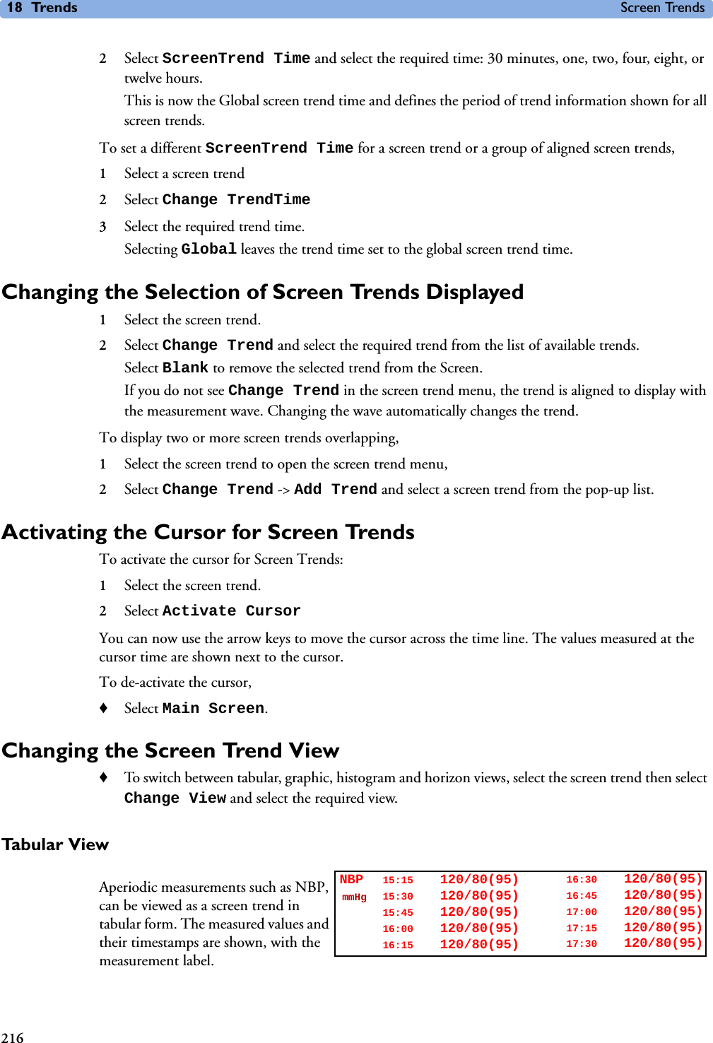
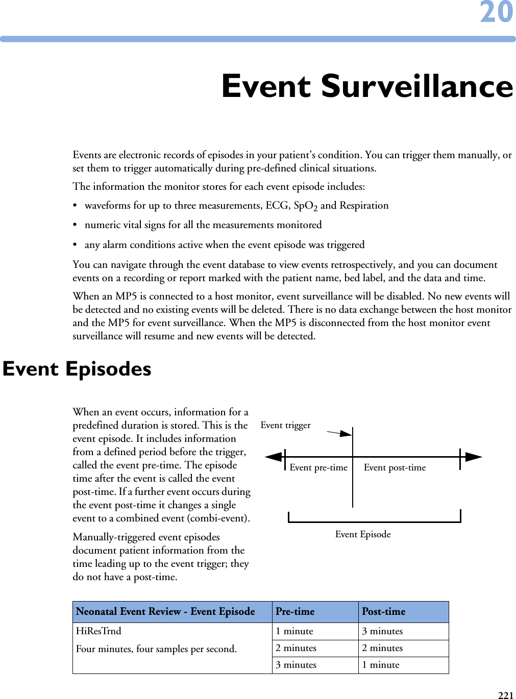
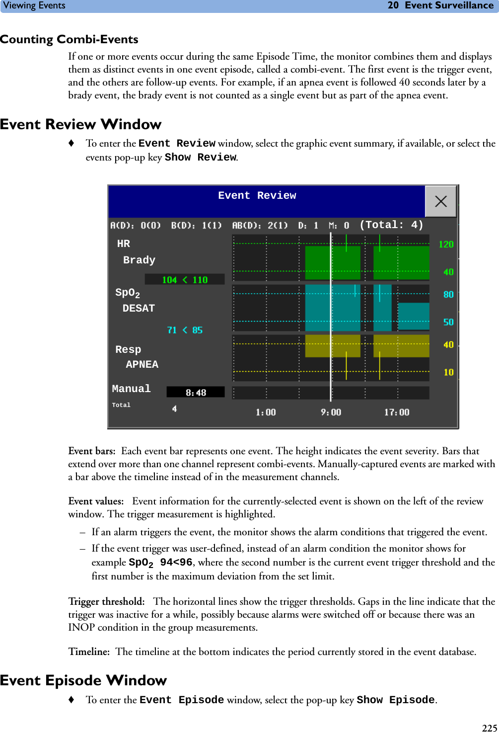
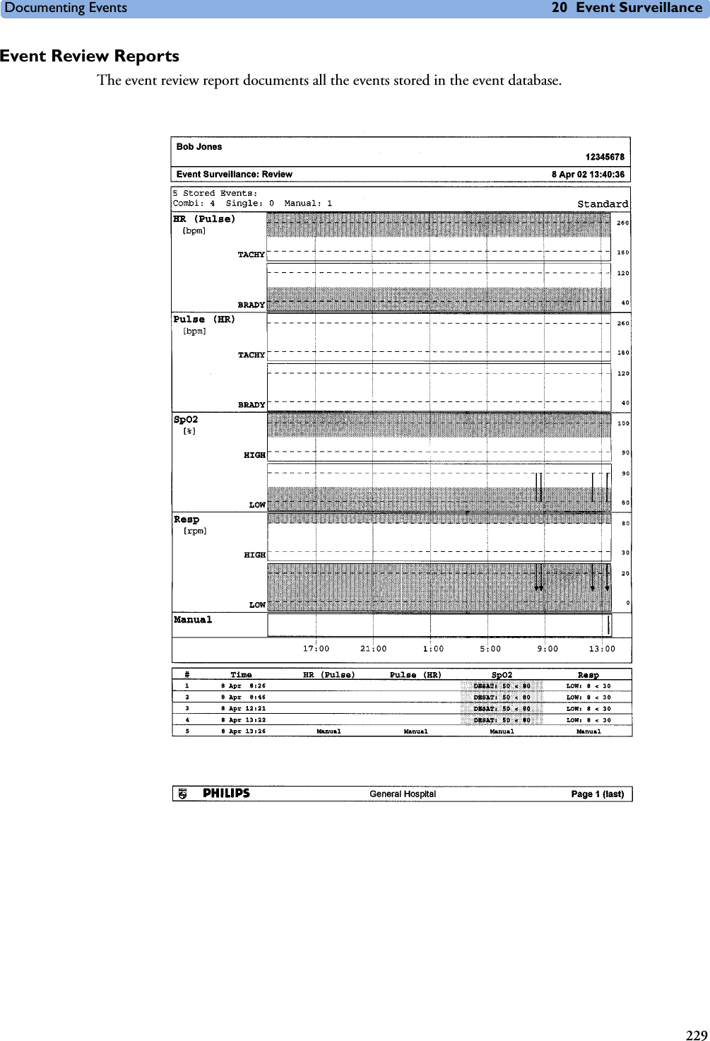
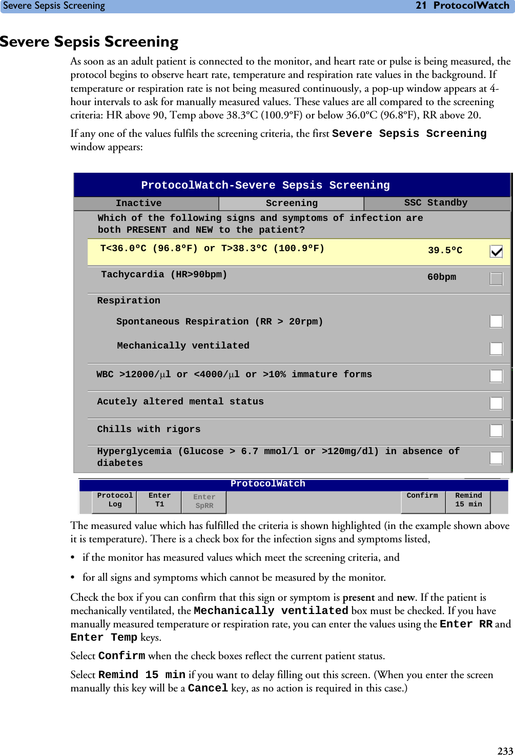
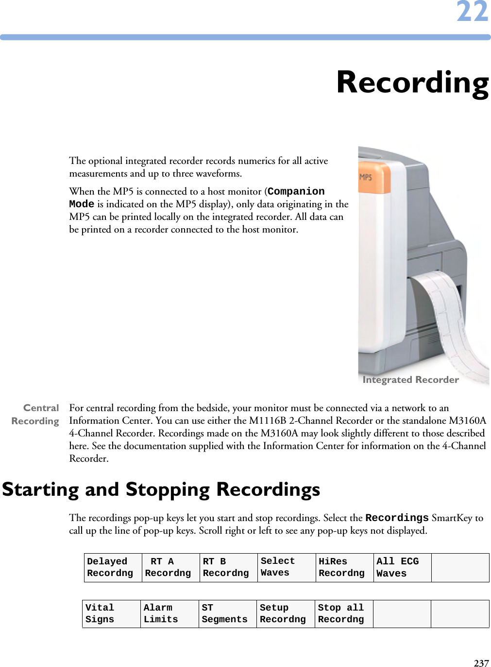
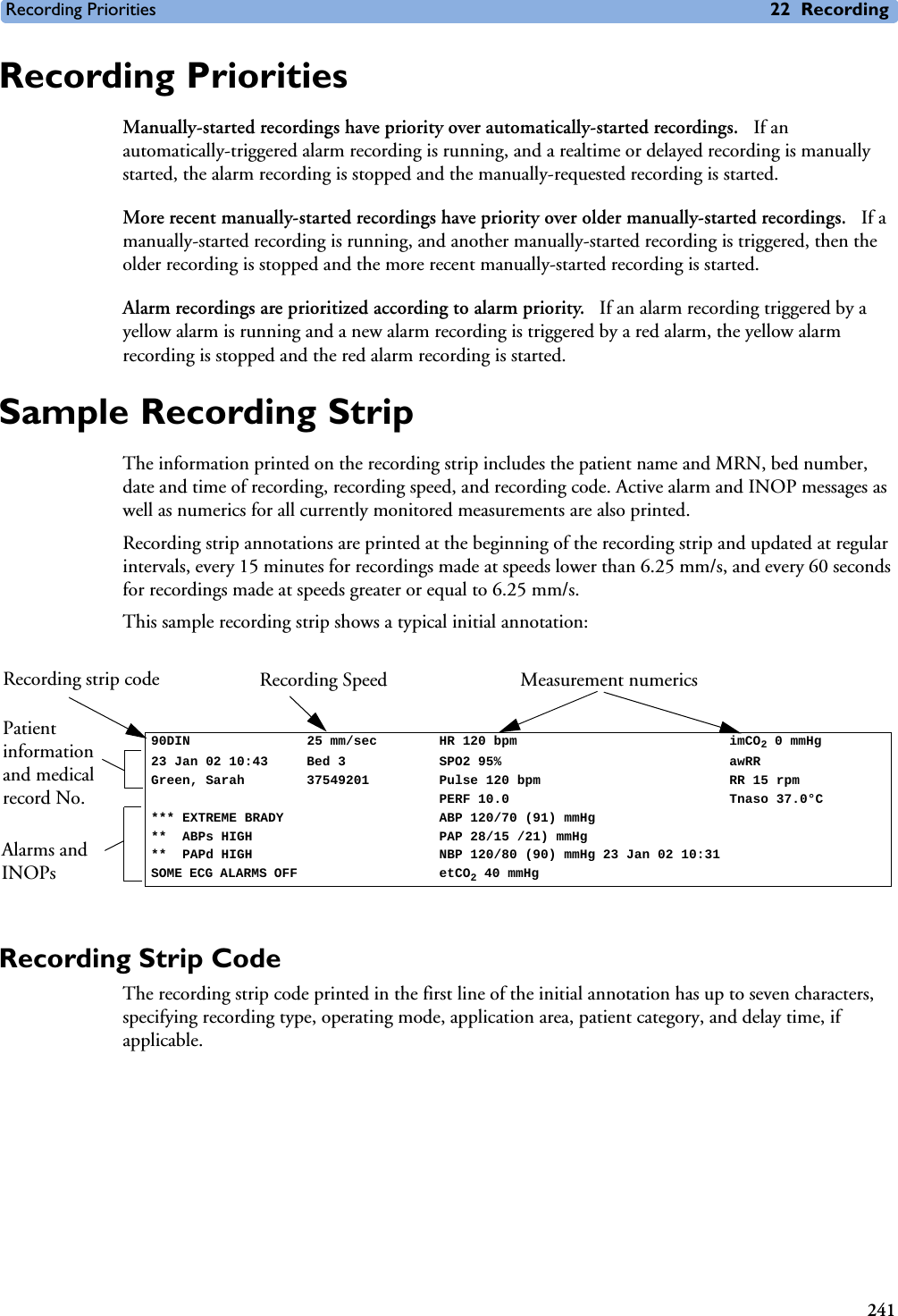
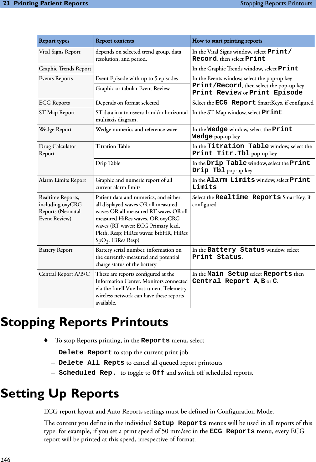
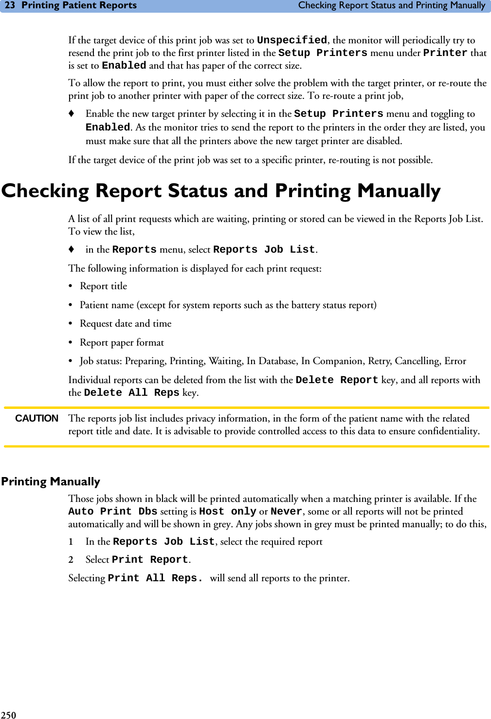
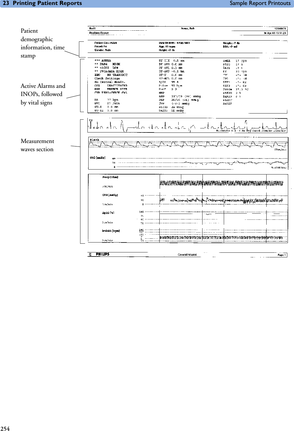
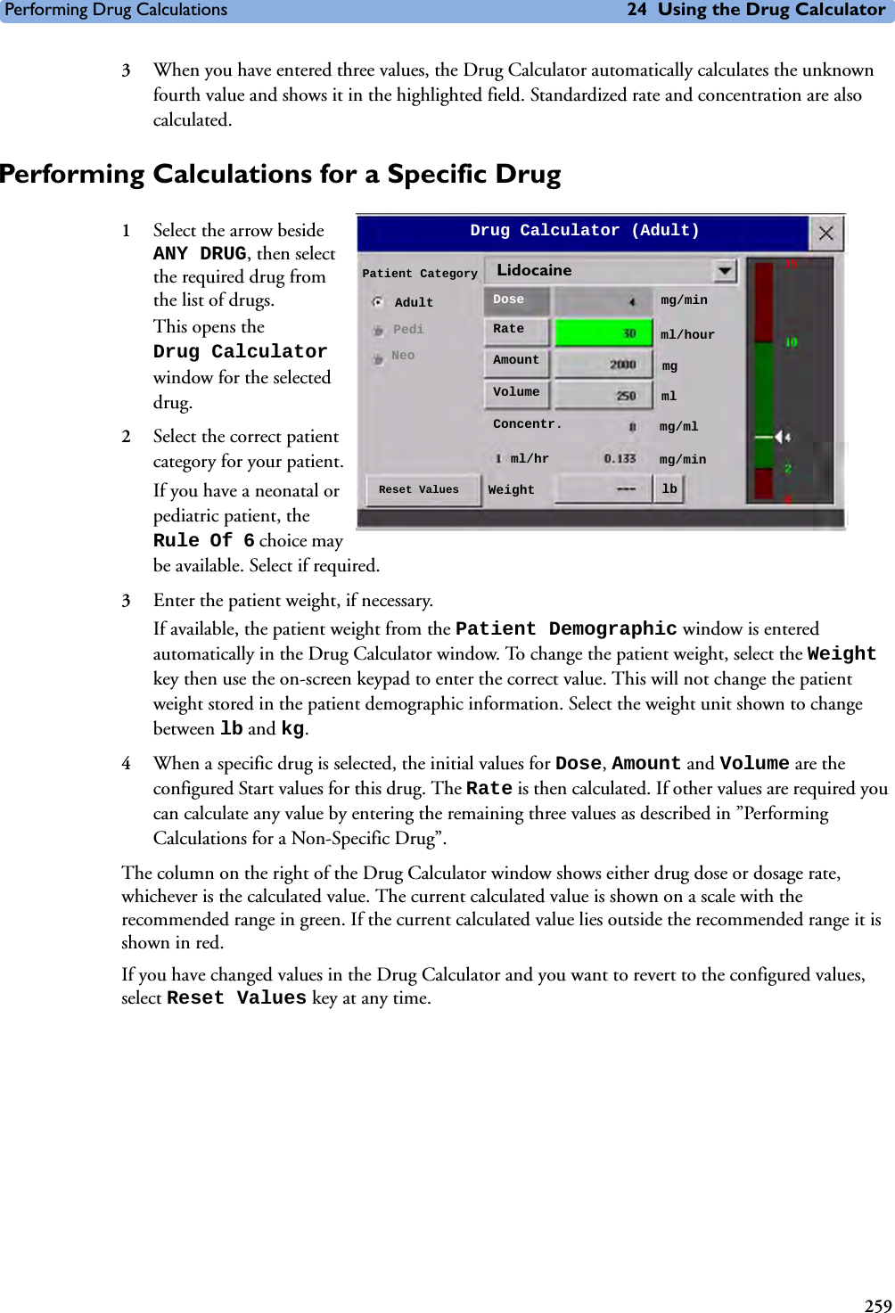
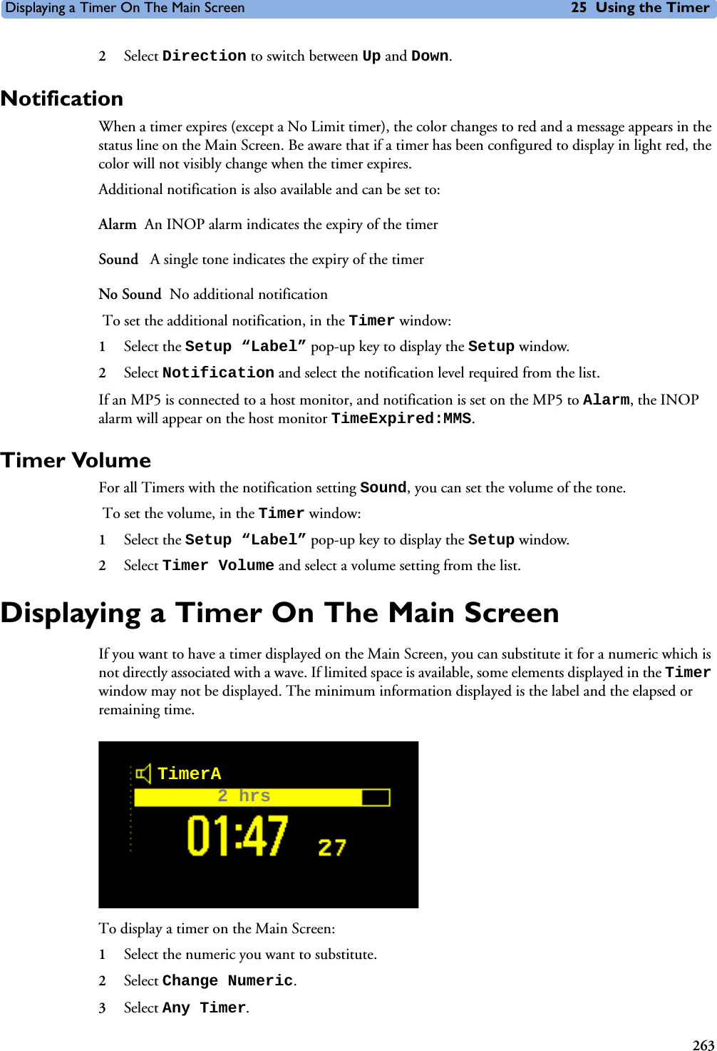
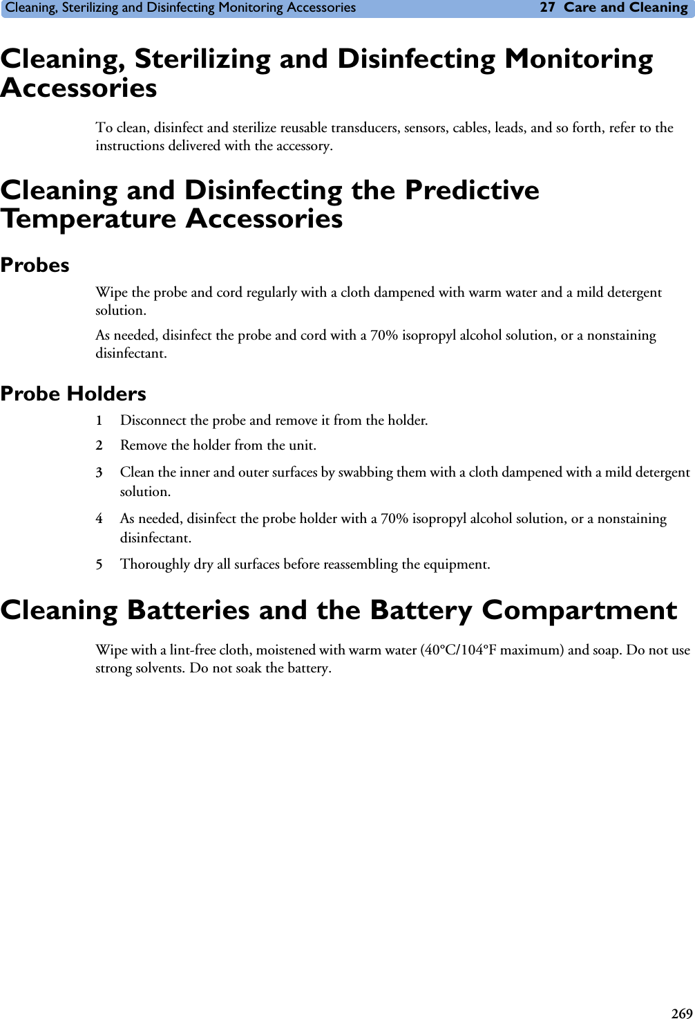
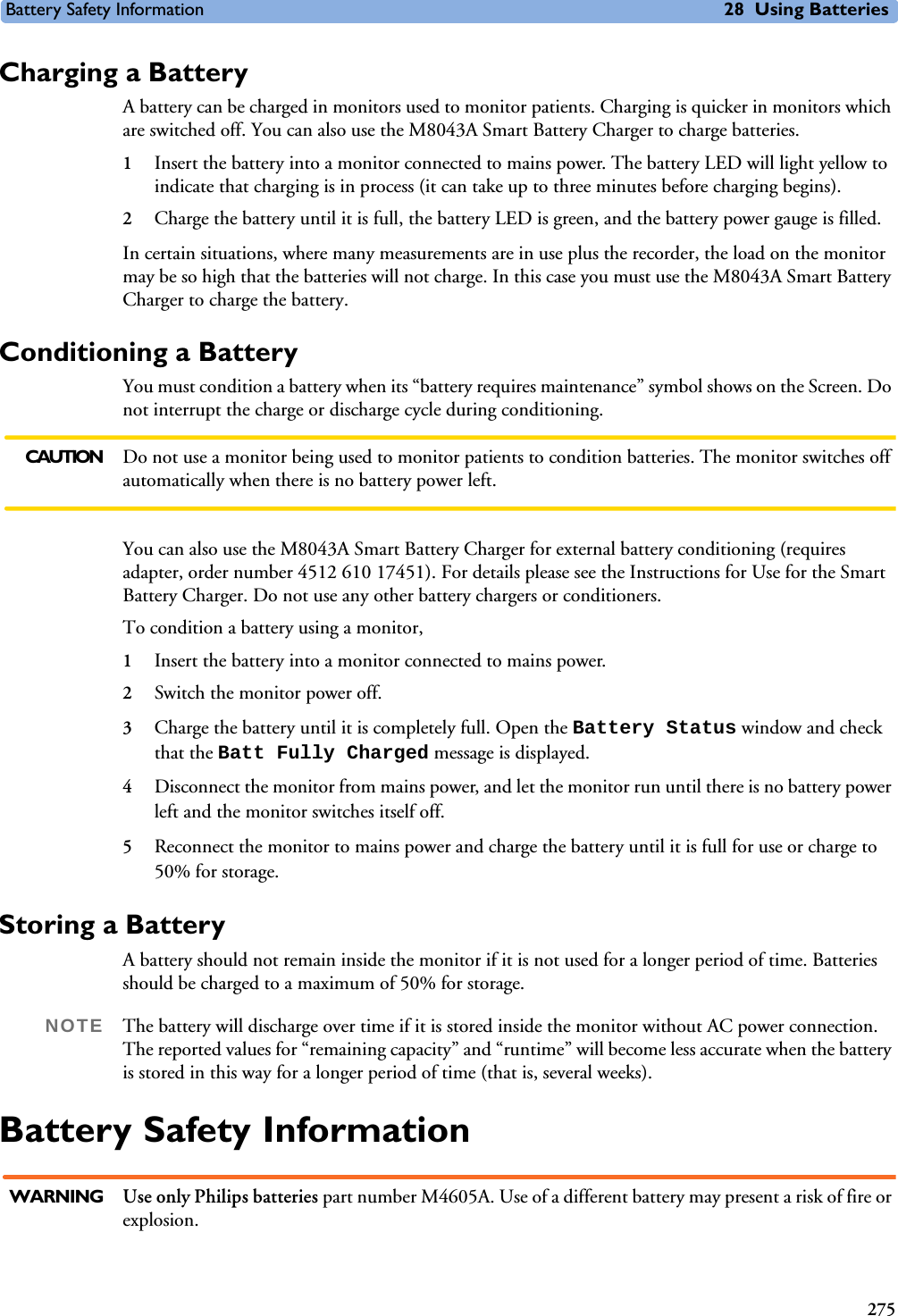
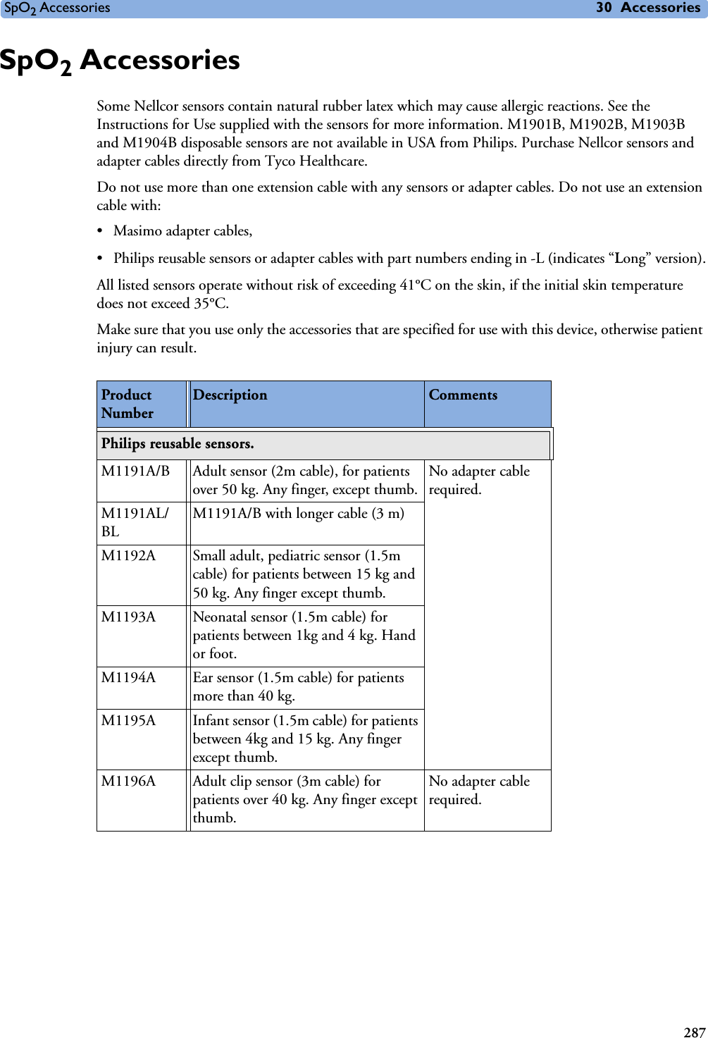
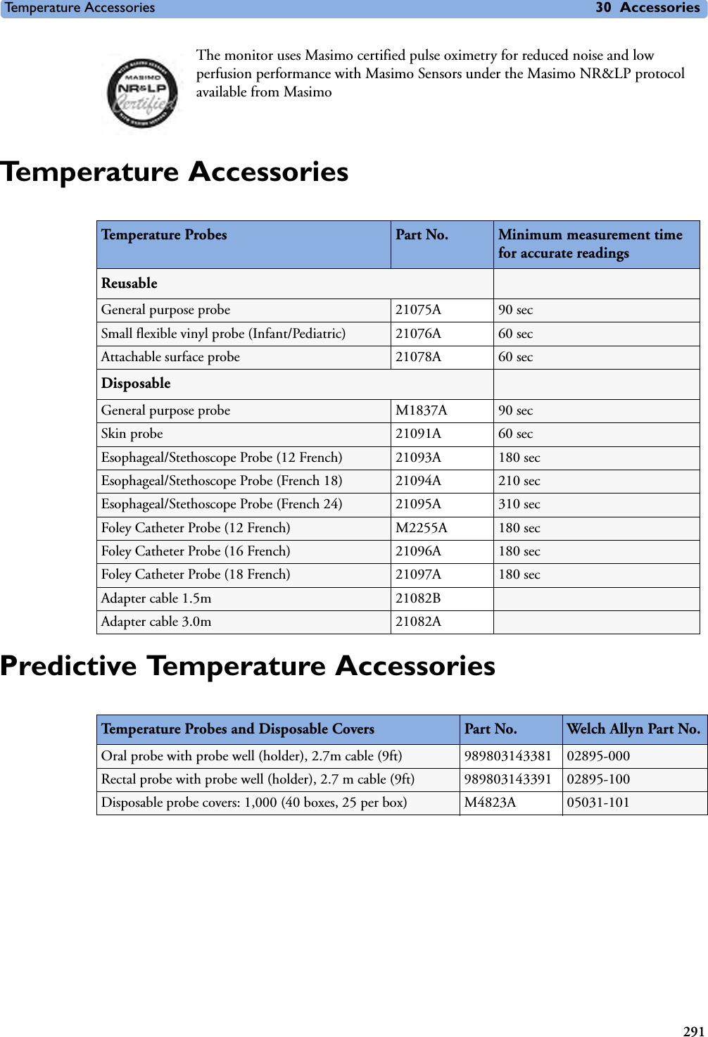
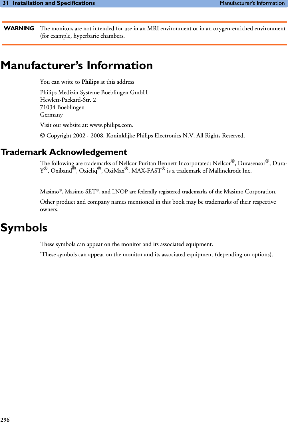
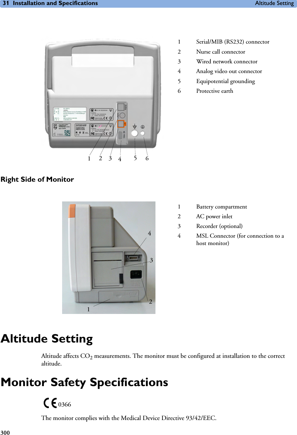
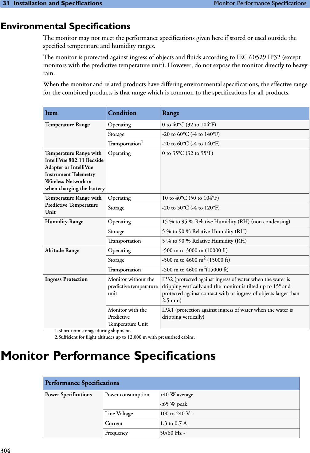
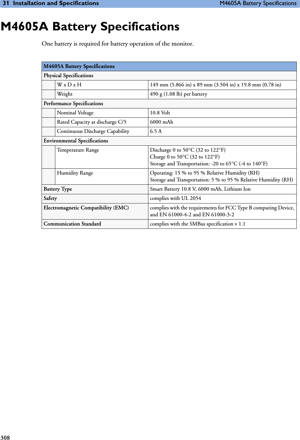
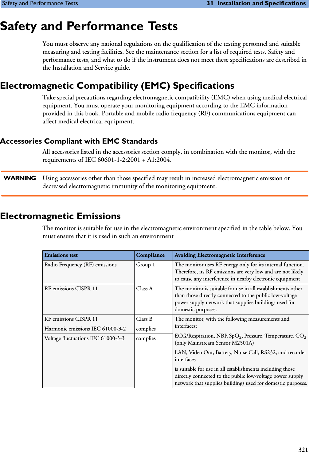
![Technical Alarm Messages (INOPs) 5 Patient Alarms and INOPs71EEG IMPEDANCE HIGH or EEG1 and/or EEG2 IMPED. HIGH EEG The signal electrode in one or both channels exceeds the user-selected impedance limit, or the impedance of a single electrode exceeds the limit. Check the impedance. If the impedance is too high, reconnect the electrodes according to the EEG monitoring setup guidelines. If the INOP persists, contact your service personnel. EEG<X> LEAD OFF <n>[X = channel, n = electrode]EEG Reconnect specified electrode.EEG<X> LEAD OFF[X = channel]at Information CenterEEG One or more electrodes are not connected. Check in the EEG Impedance/Montage window on the monitor which electrode(s) are affected and reconnect the electrodes.EEG<X> LEADS OFF[X = channel]EEG Two or more electrodes are not connected. Check in the EEG Impedance/Montage window which electrodes are affected and reconnect the electrodes.EEG LINE NOISEEEG 1 or 2 LINE NOISEEEG Excessive line noise has been detected in either channel EEG1 or EEG2, or in both EEG channels. Keep all cables together and away from metallic bodies, other cables & radiated fields.EEG MUSCLE NOISEEEG 1 or 2 MUSCLE NOISEEEG Too much power above 30 Hz has been detected in channel EEG1 or EEG2, or both. Check the Electrode-to-Skin Impedance and reposition the electrode away from possible muscle activity, if necessary.EEG NO TRANSDUCERINOP toneEEG The trunk cable is disconnected from the EEG plug-in module. Reconnect the trunk cable. Silencing this INOP switches the measurement off. EEG UNPLUGGEDINOP toneEEG Plug in module. Silencing this INOP switches off the measurement.EEG OVERRANGE, or EEG<X> OVERRANGEEEG Input signal is too high in one or both channels. This is usually caused by interfering signals such as line noise or electro-surgery. X denotes the EEG channel.FAP INOPS PRESS See <Pressure label> INOPS (under Pressure).FMS UNPLUGGED INOP tone.FMS Make sure that the Flexible Module Rack is connected to the monitor. All FMS measurements are off while the FMS is unplugged.FMS UNSUPPORTEDINOP tone.FMS The Flexible Module Rack is not supported by your monitor. Contact your service personnel.IC1/IC2 INOPS PRESS See <Pressure label> INOPS (under Pressure).ICP INOPs PRESS See <Pressure label> INOPS (under Pressure).Indep.Dsp Malfunc. Display A problem has occurred with the second main display. Contact your service personnel.Indep.Dsp NotSupp. Display The monitor does not support a second main display. The monitor software is incompatible. Contact your service personnel.!!INSERT BATTERYSevere yellow INOP tone.During this INOP, alarms cannot be paused or switched off.Battery X2/MP2 only: There is no battery in the battery compartment. You cannot operate the monitor on AC mains while the battery compartment is open (not sealed with a battery). Load a battery immediately.Intell.Dsp Malf.INOP toneDisplay There is a problem with the Intelligent Display. Check the MSL coupling cable then contact your service personnel.INOP Message, Indication Source What to do](https://usermanual.wiki/Philips-Medical-Systems-North-America/SRRBV1.User-Manual-MP5-and-MP5T/User-Guide-1044633-Page-81.png)

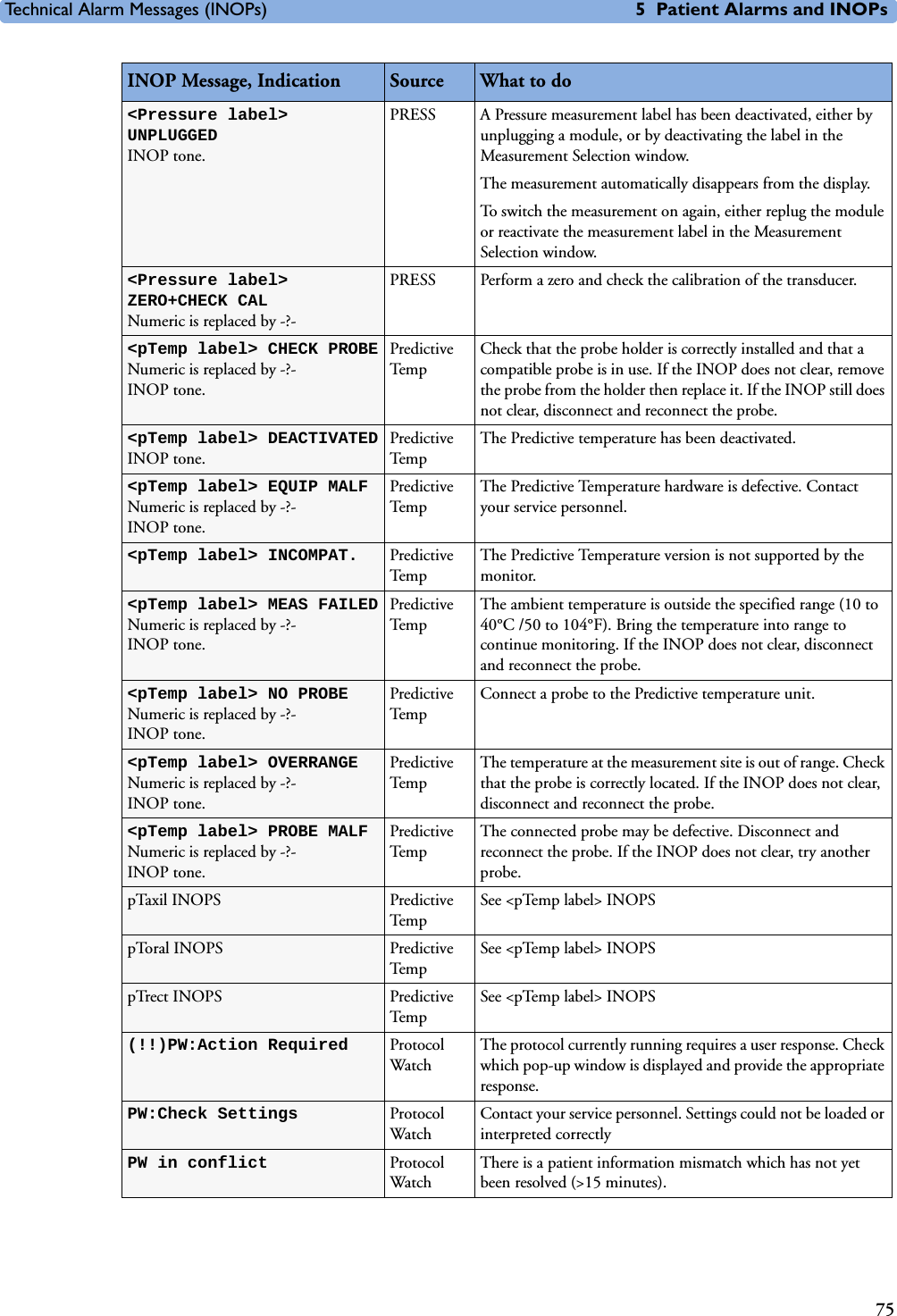
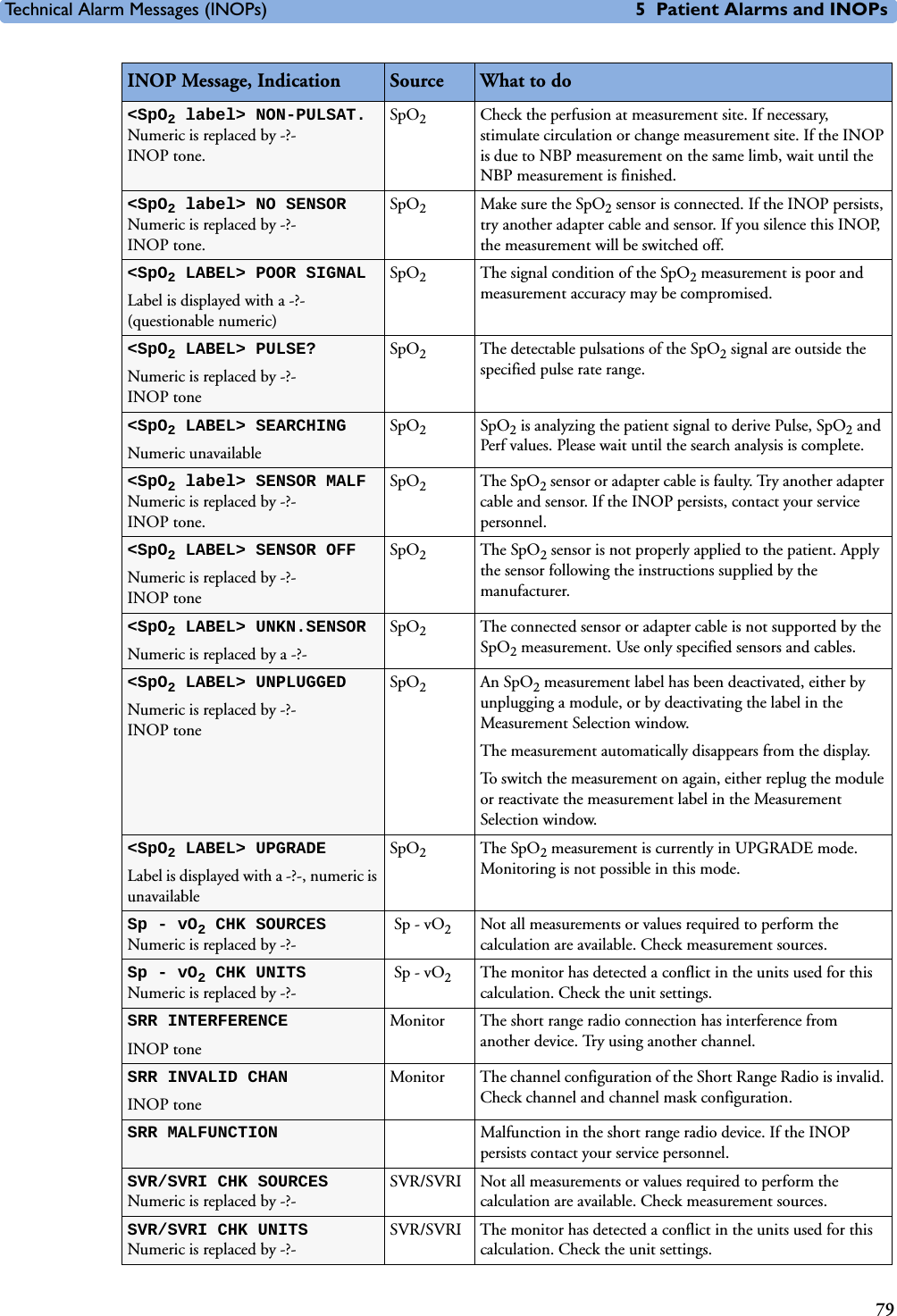
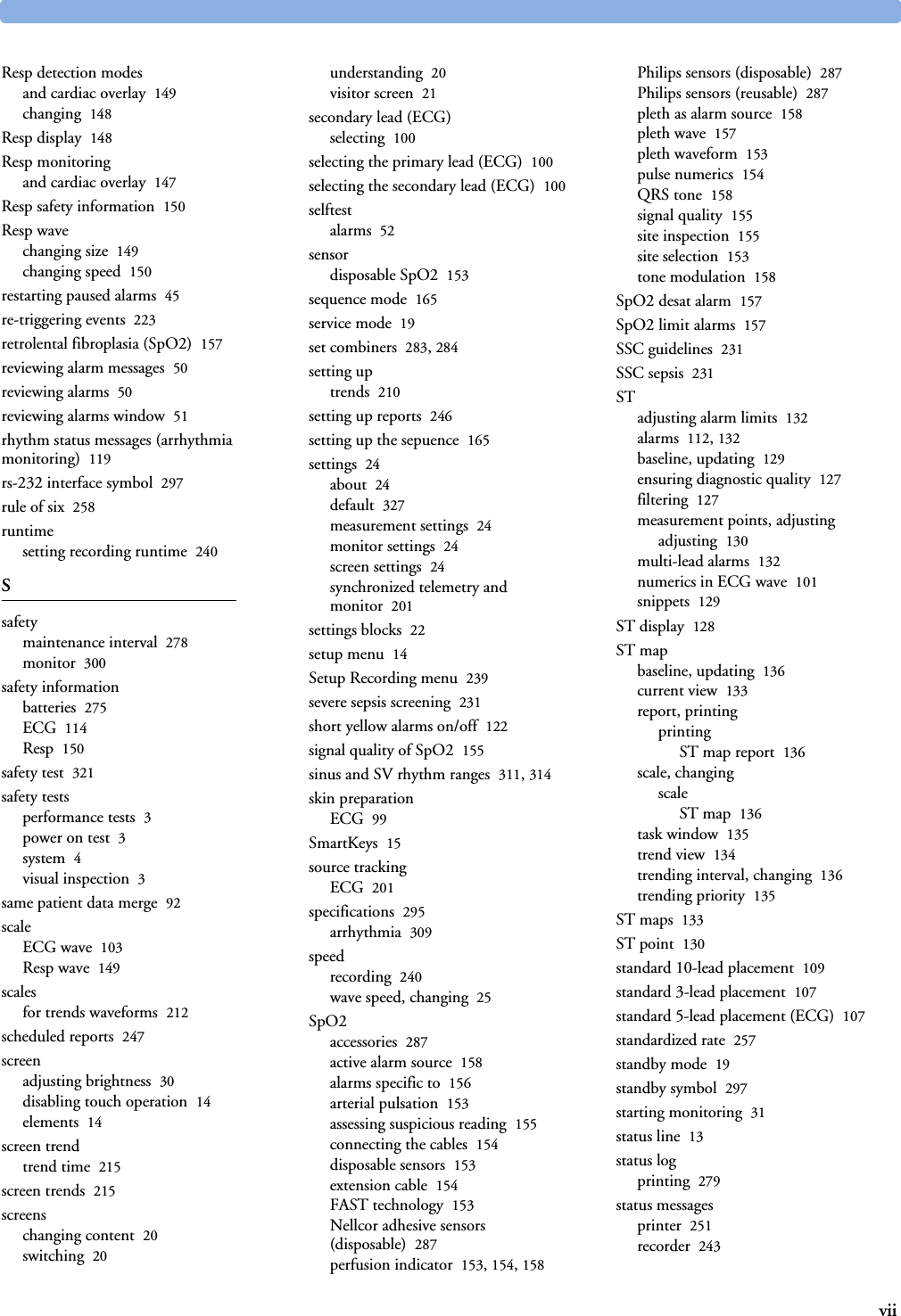
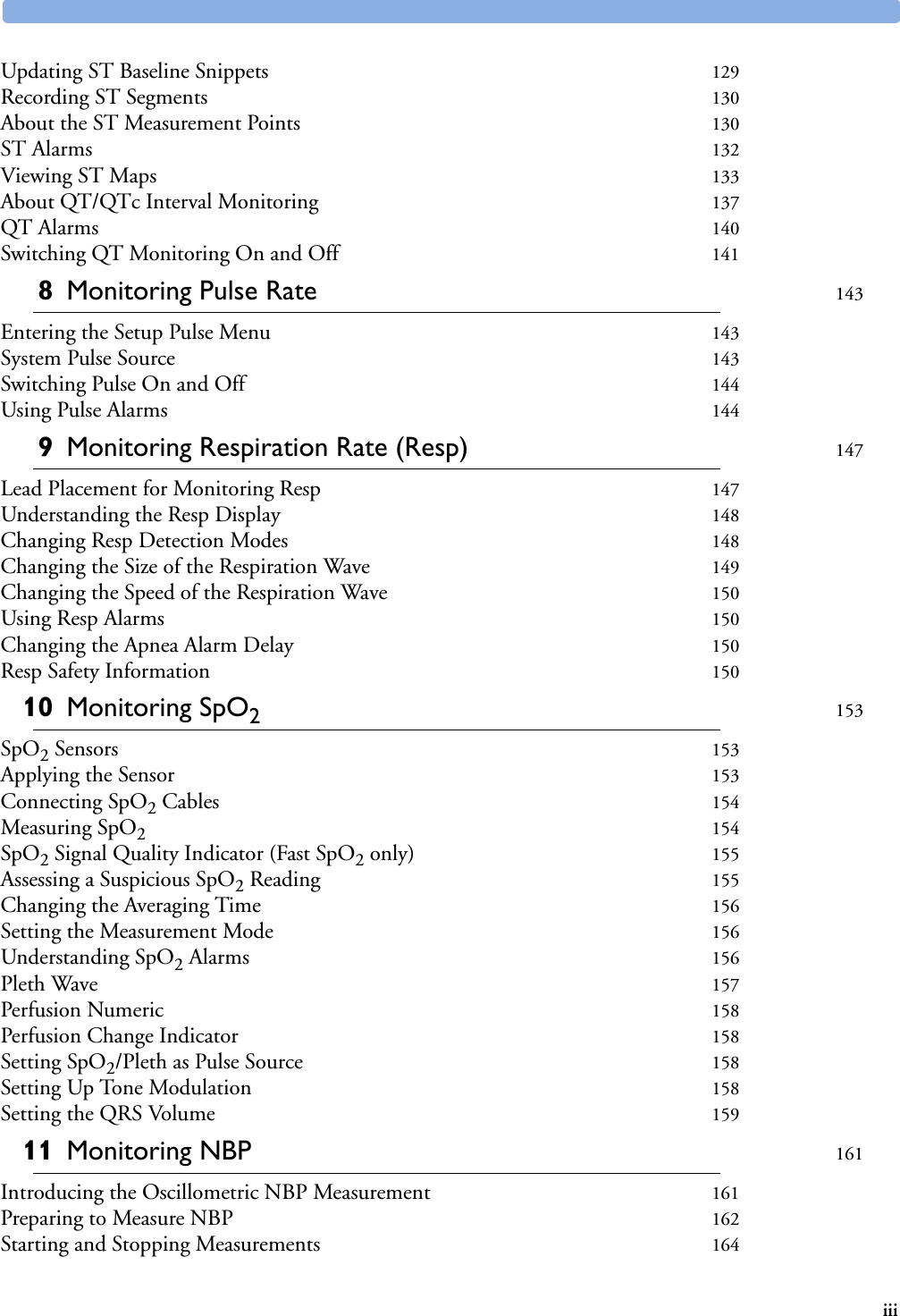
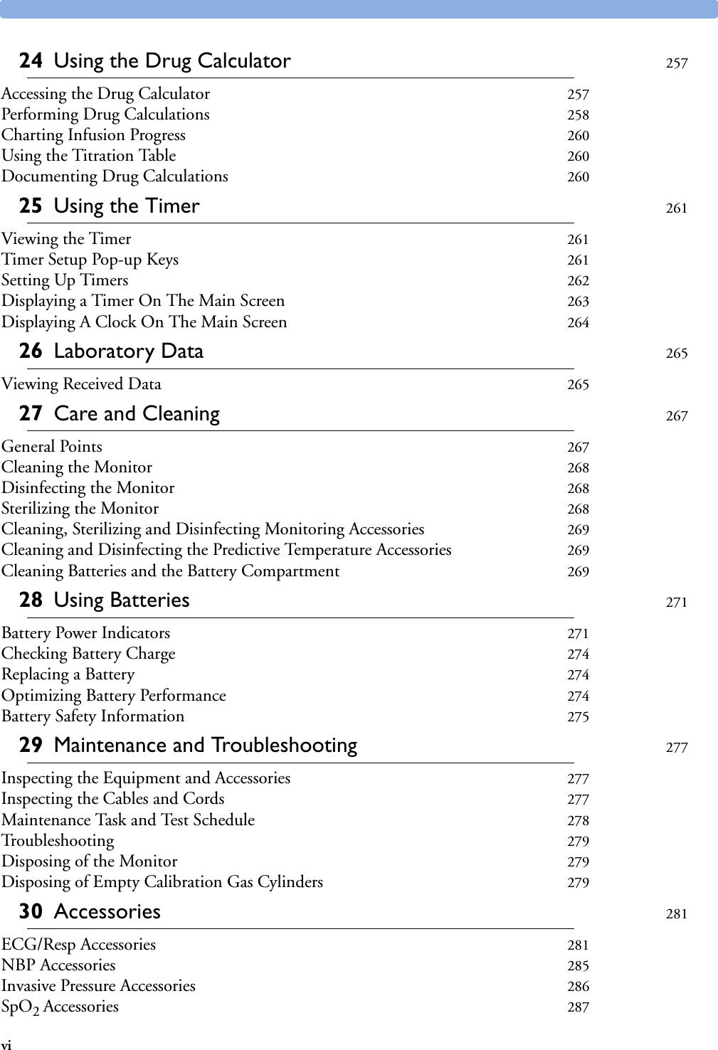
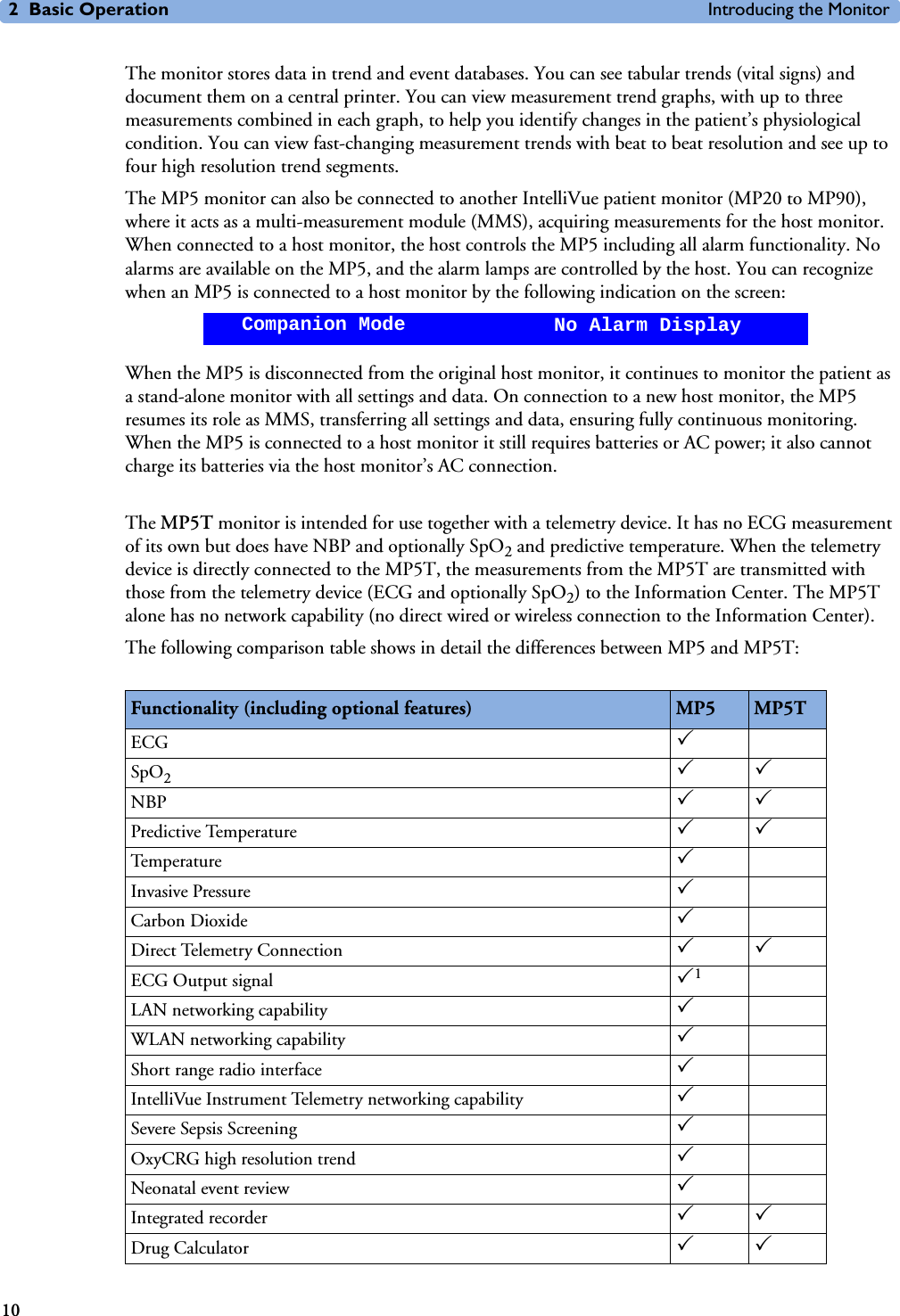
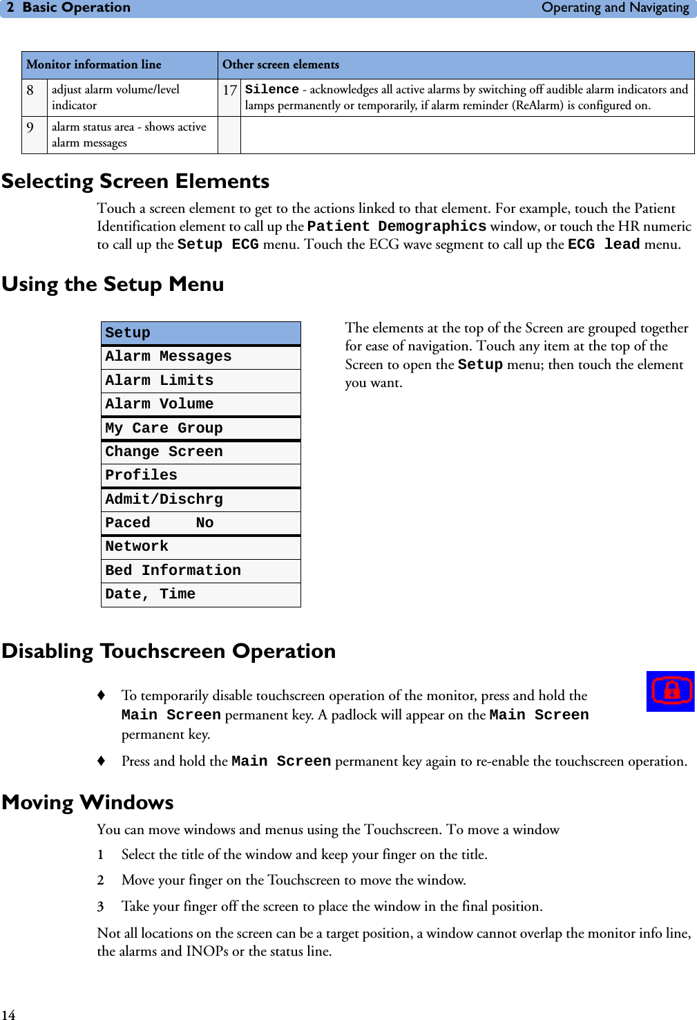
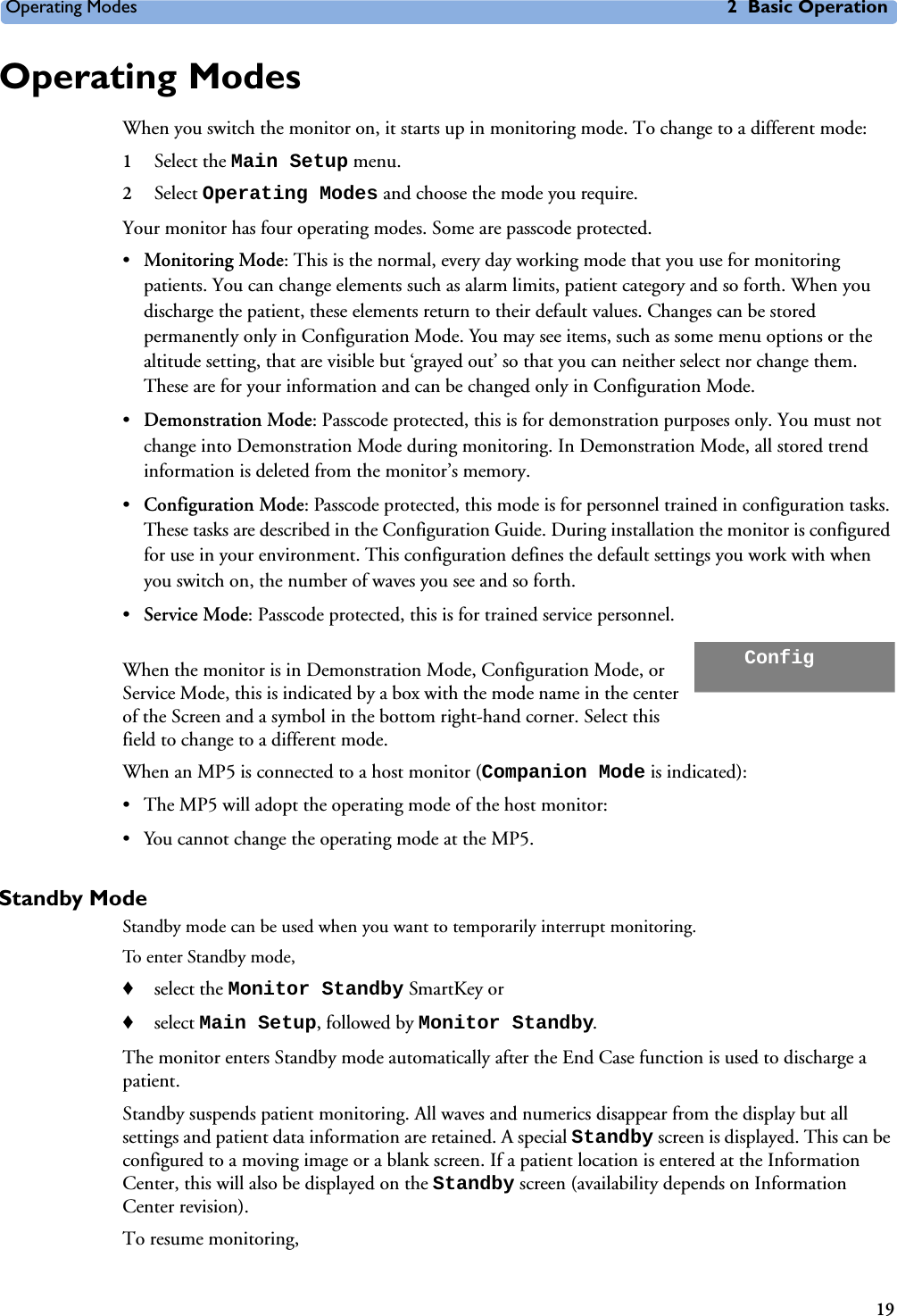
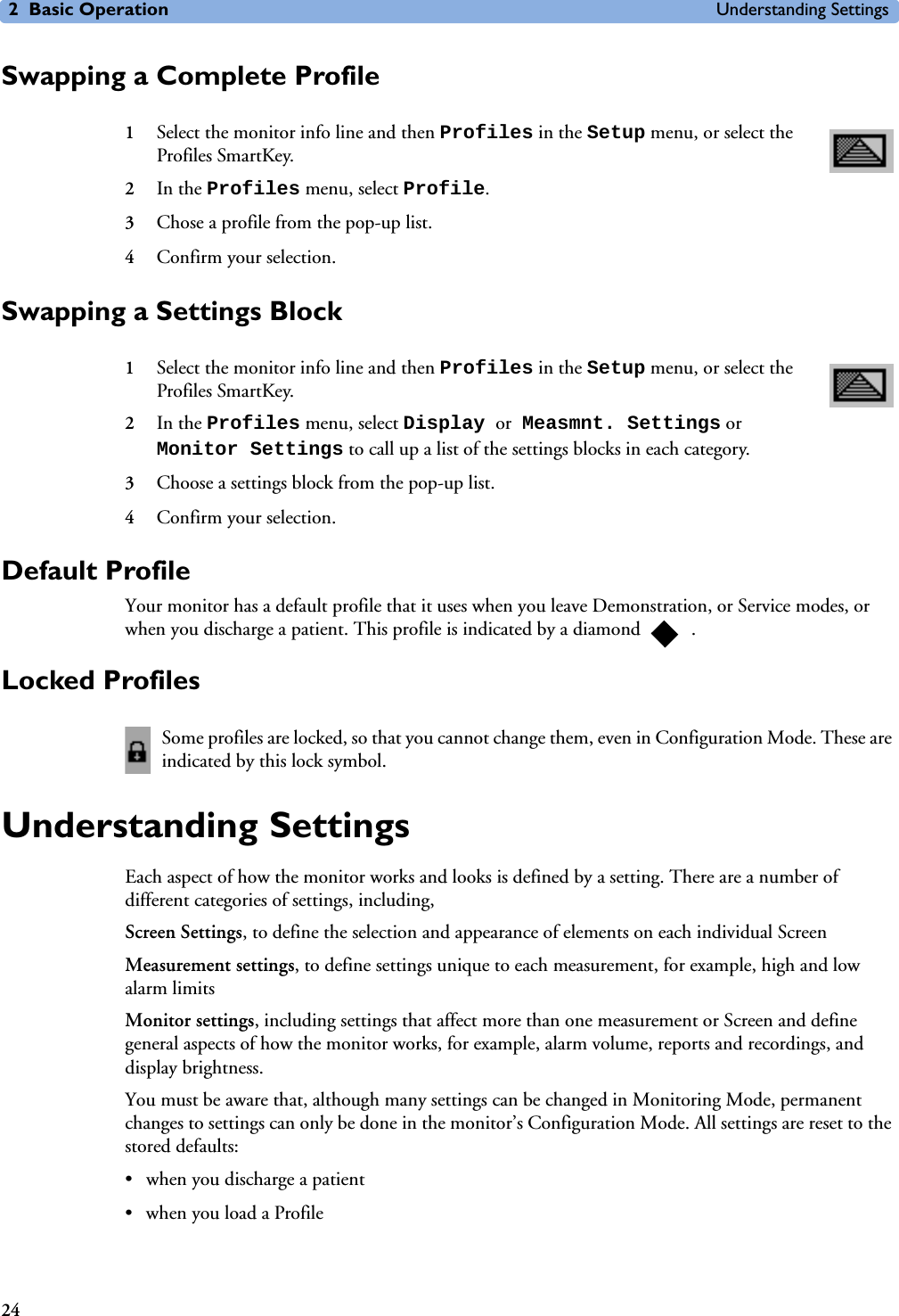
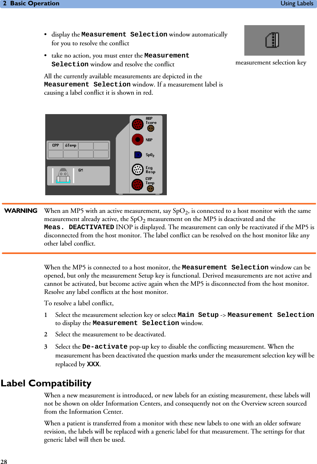
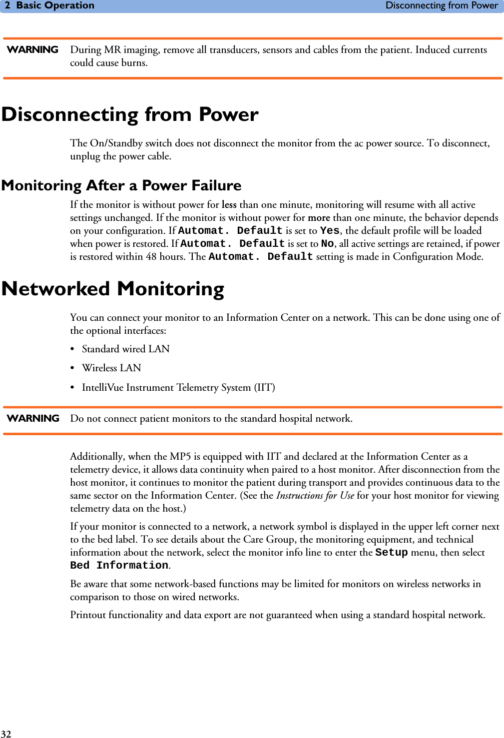
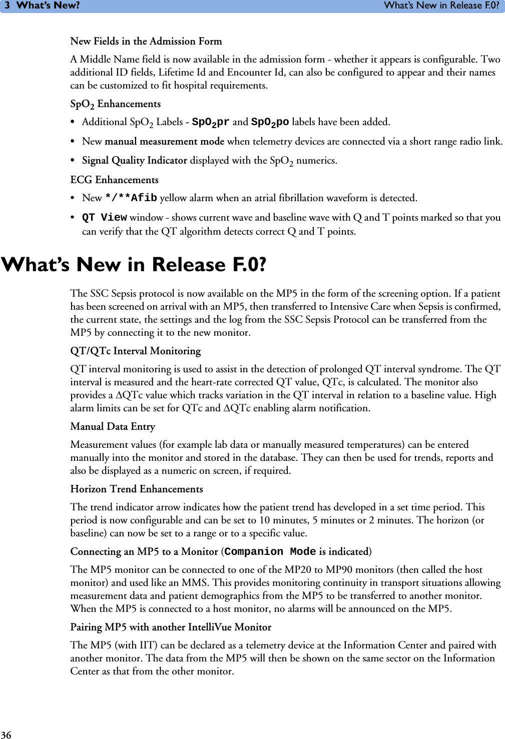
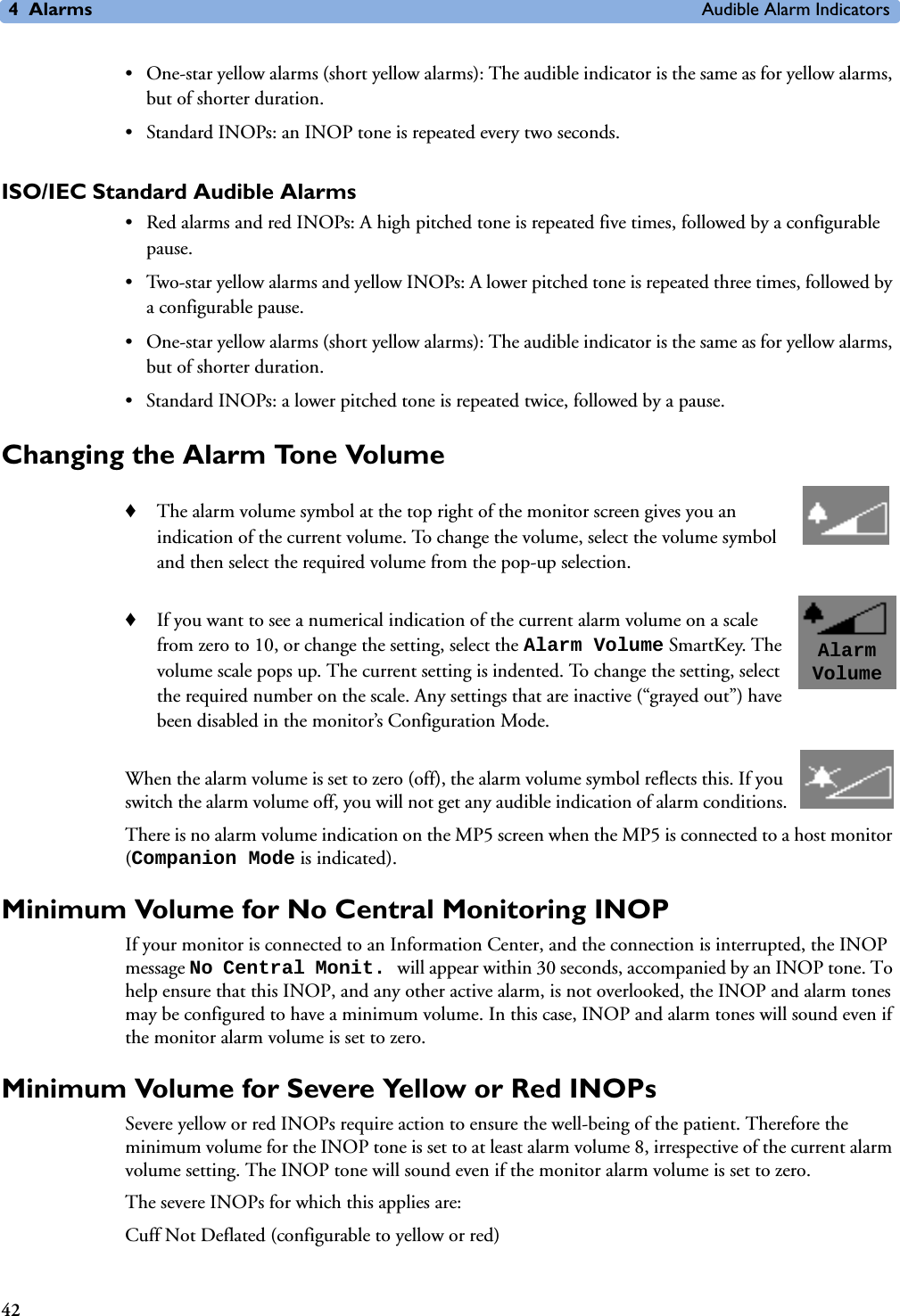
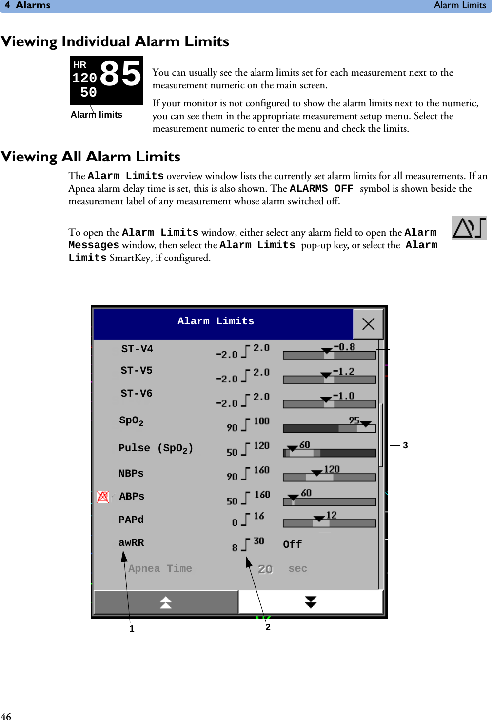
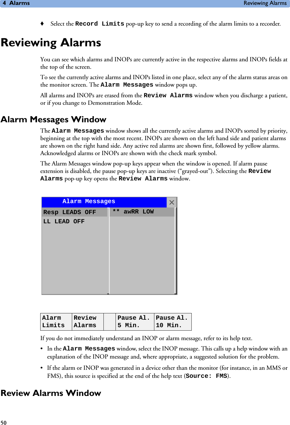
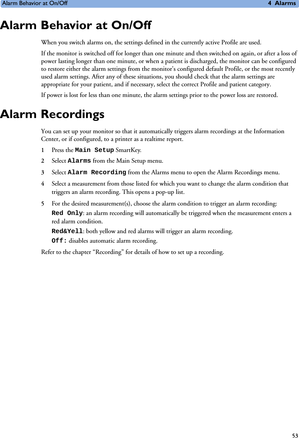
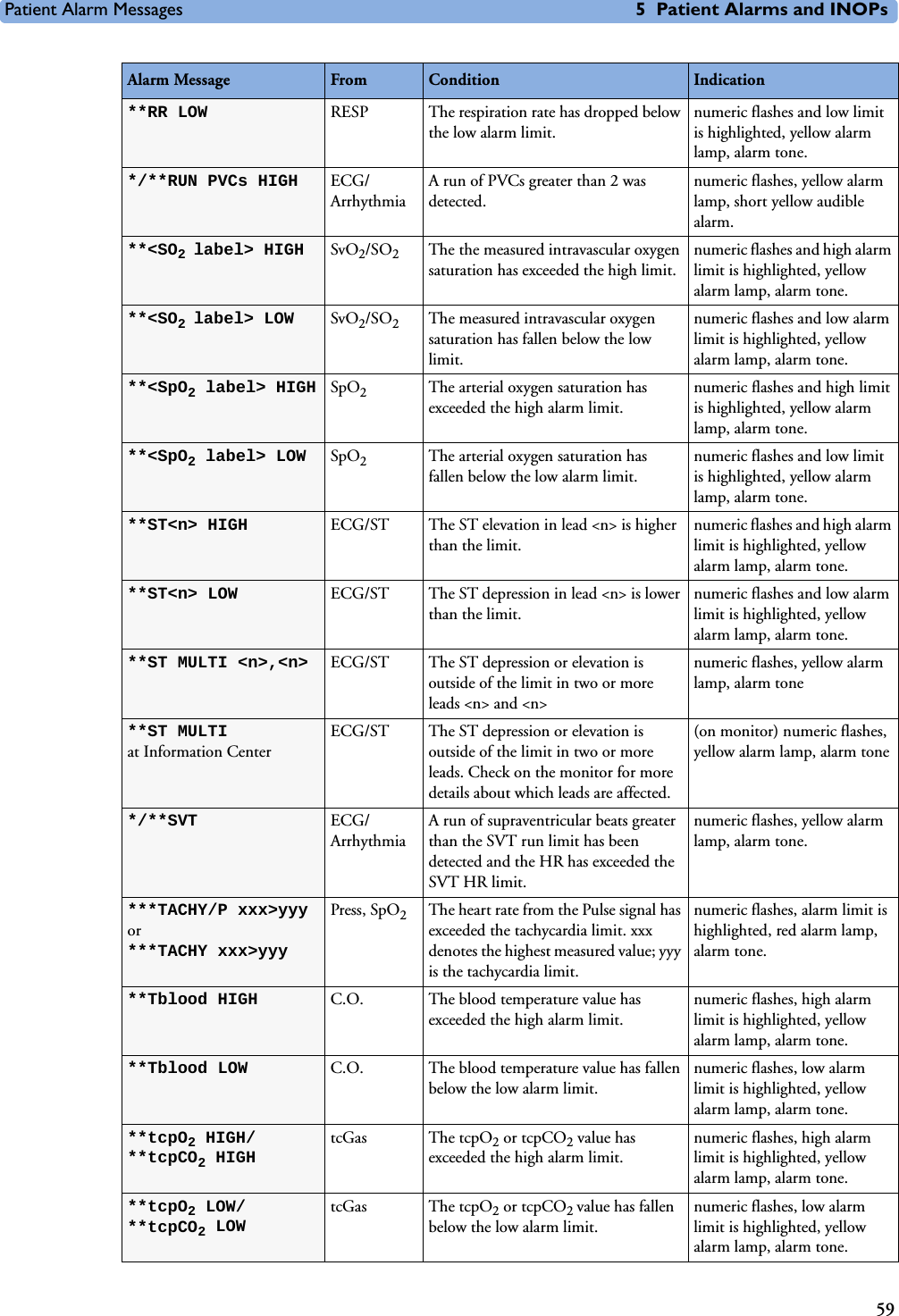
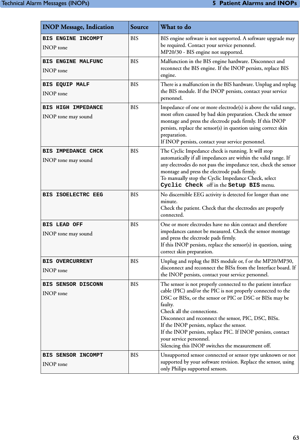
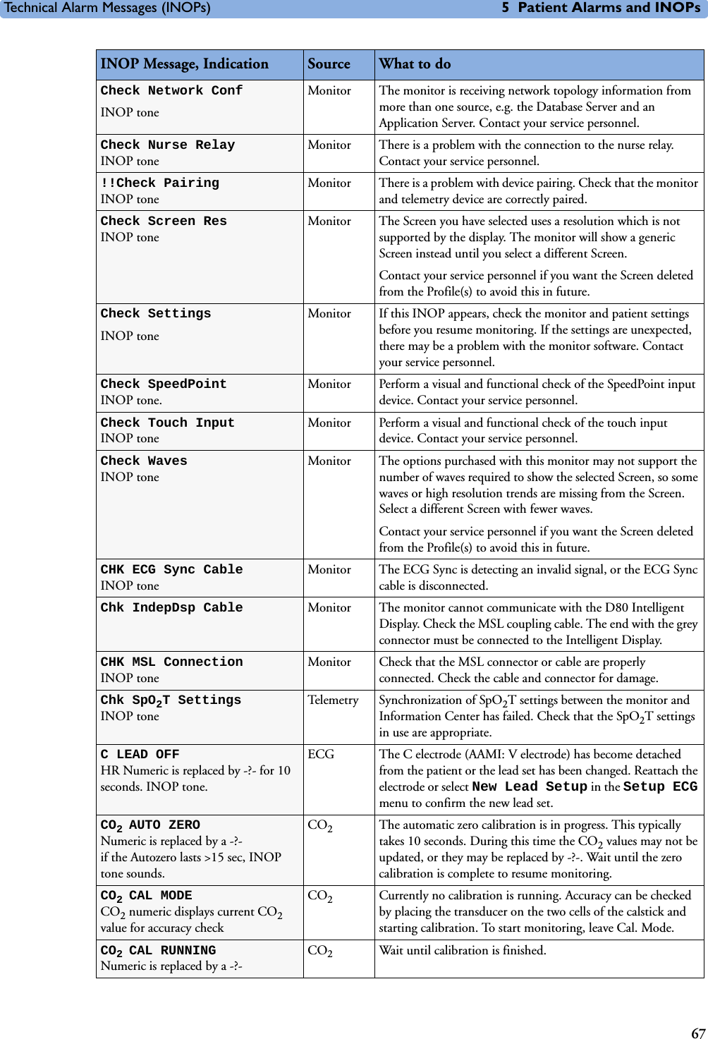
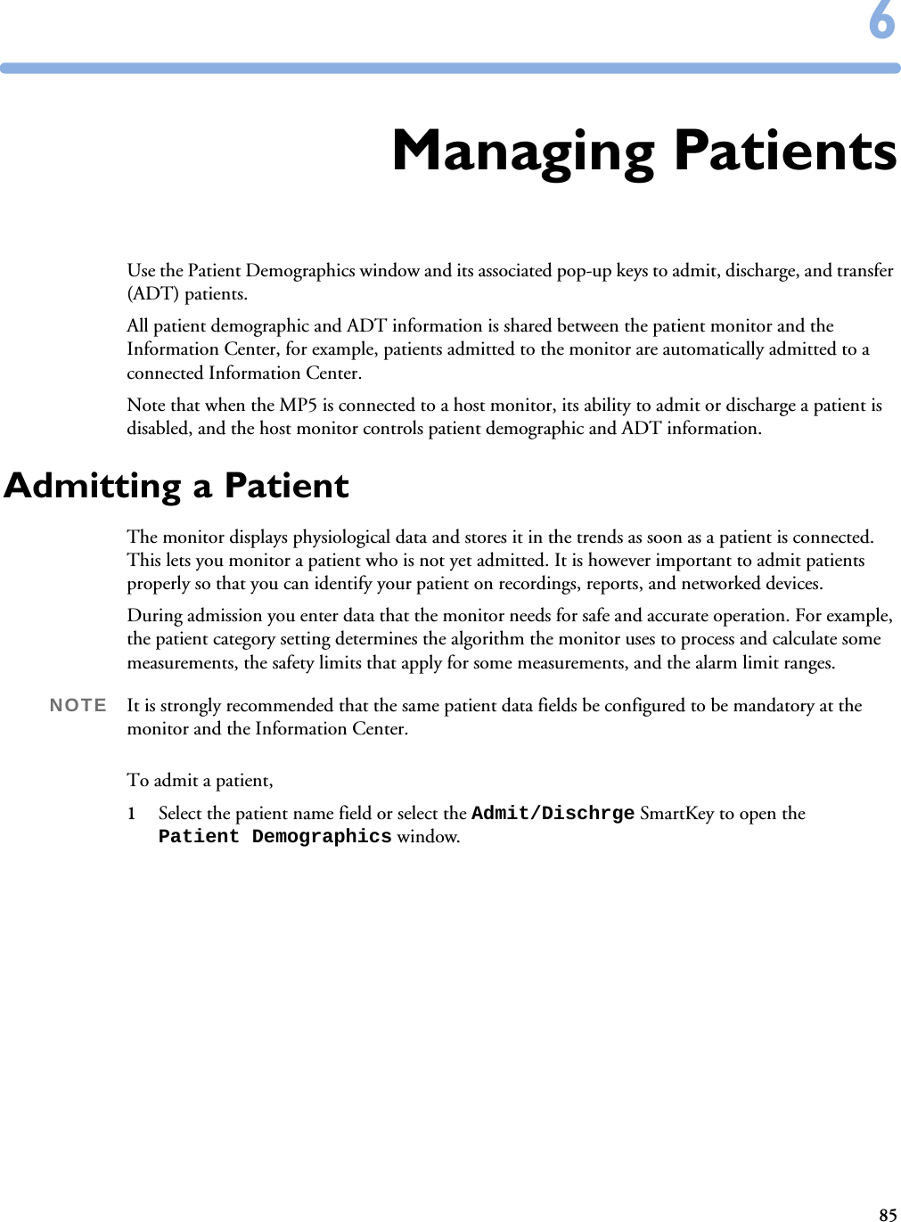
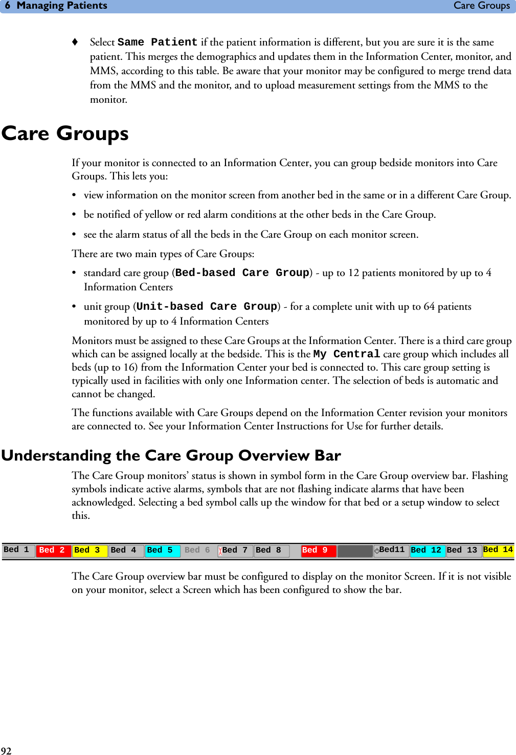
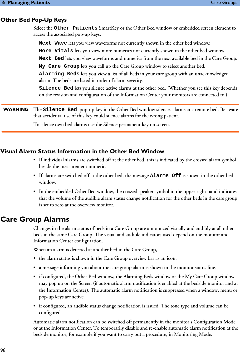
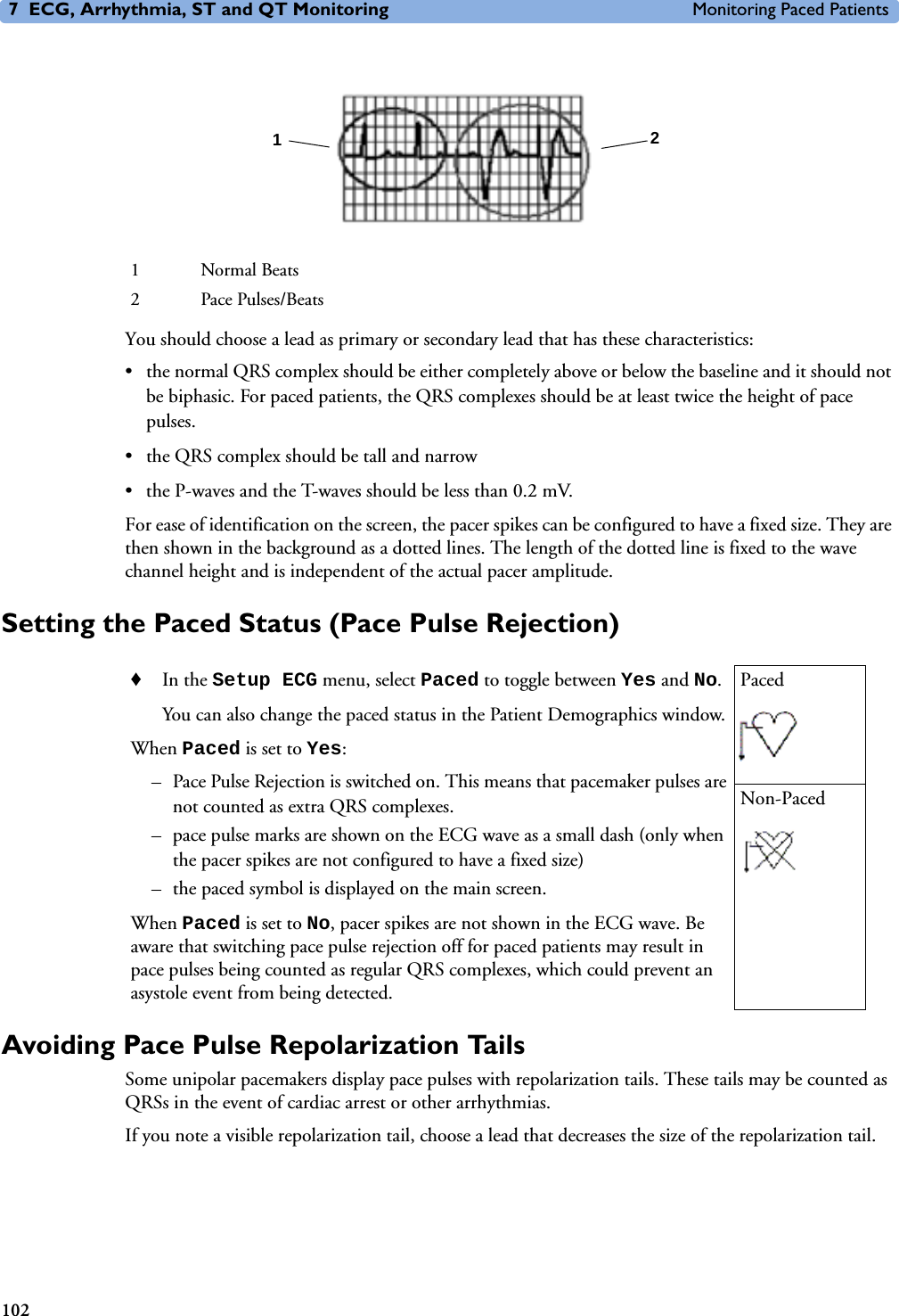
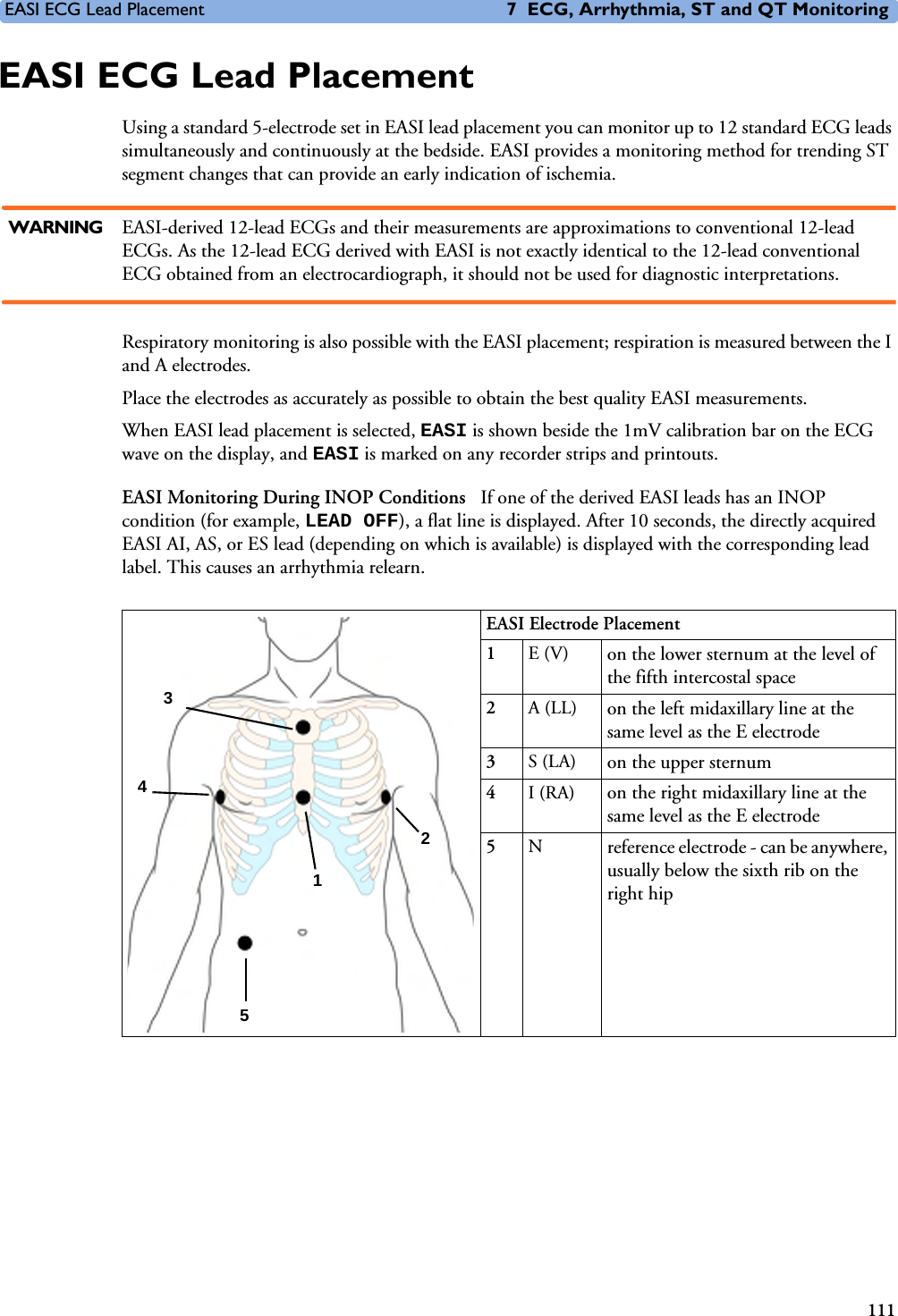
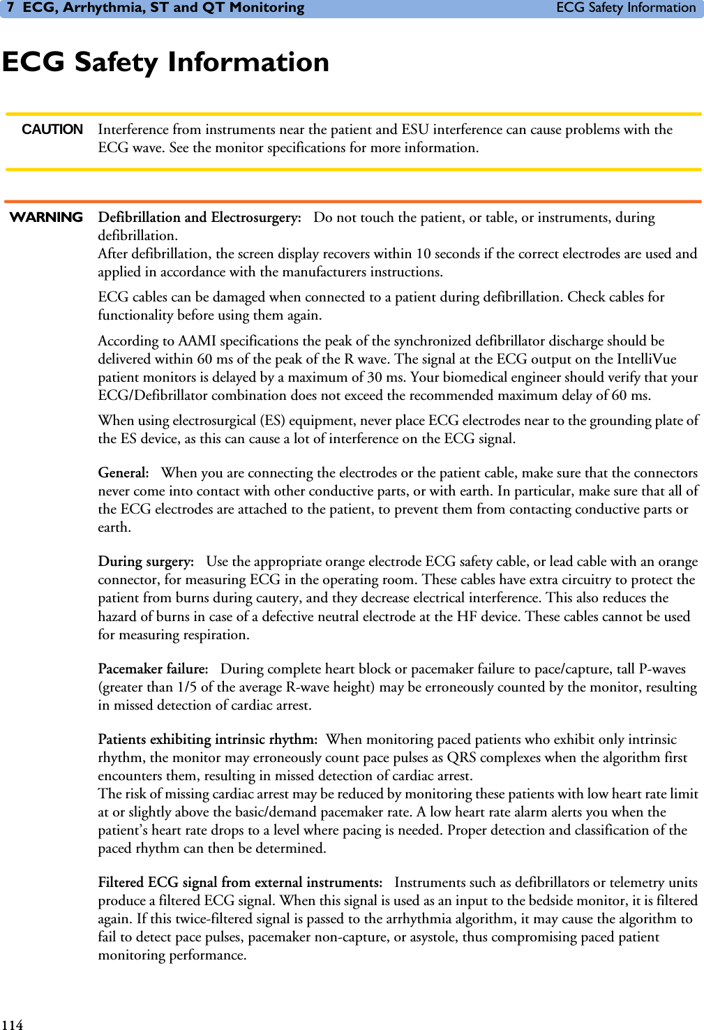
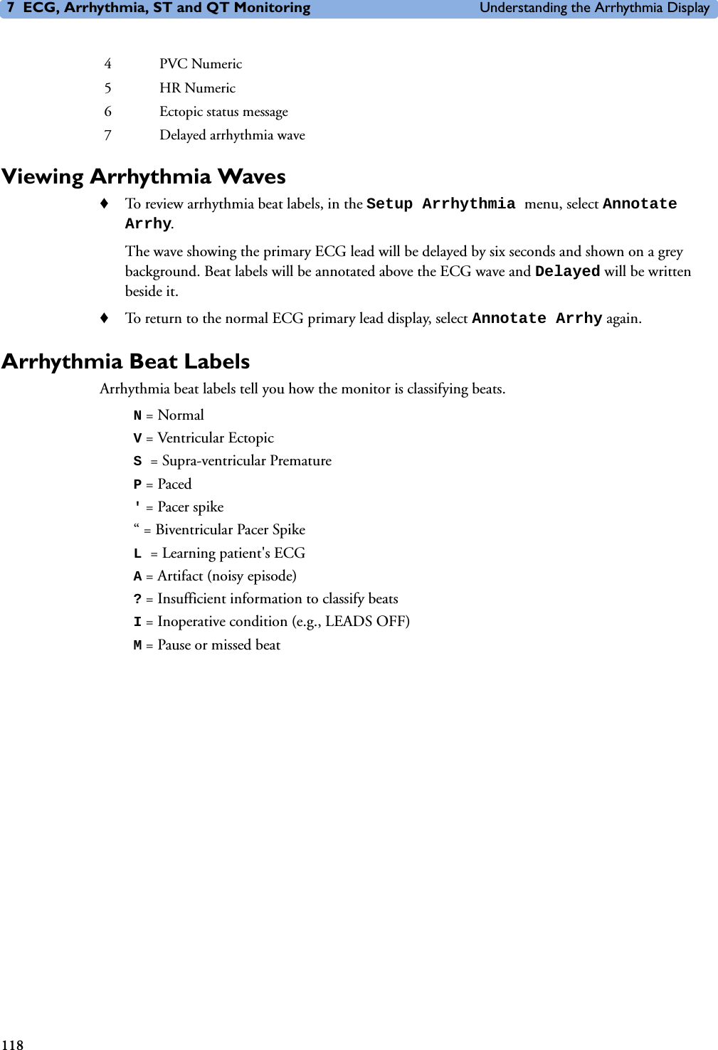
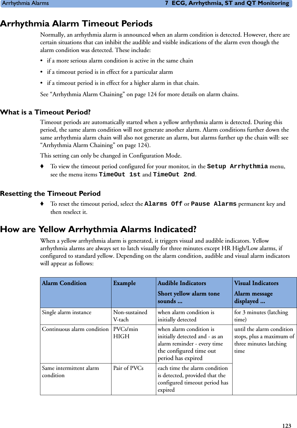
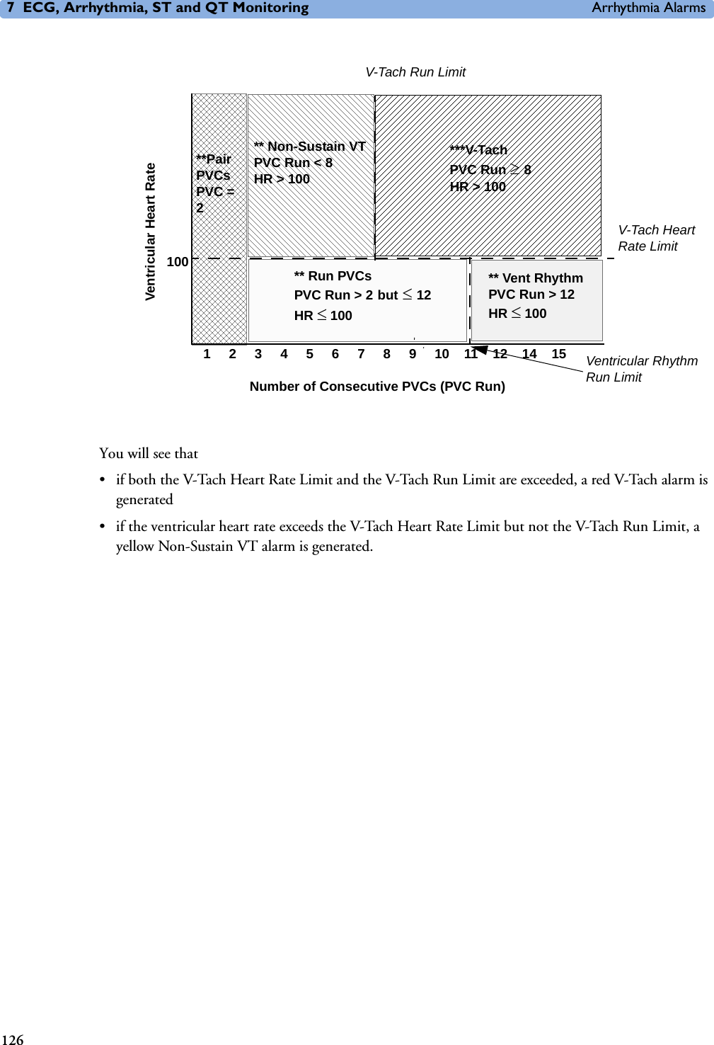
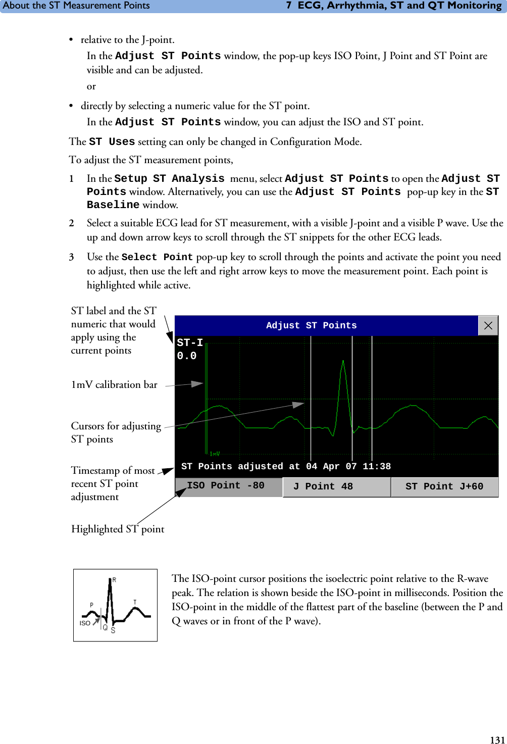
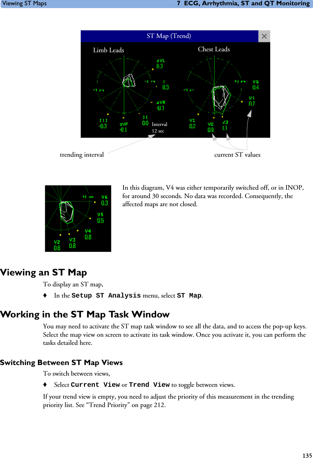
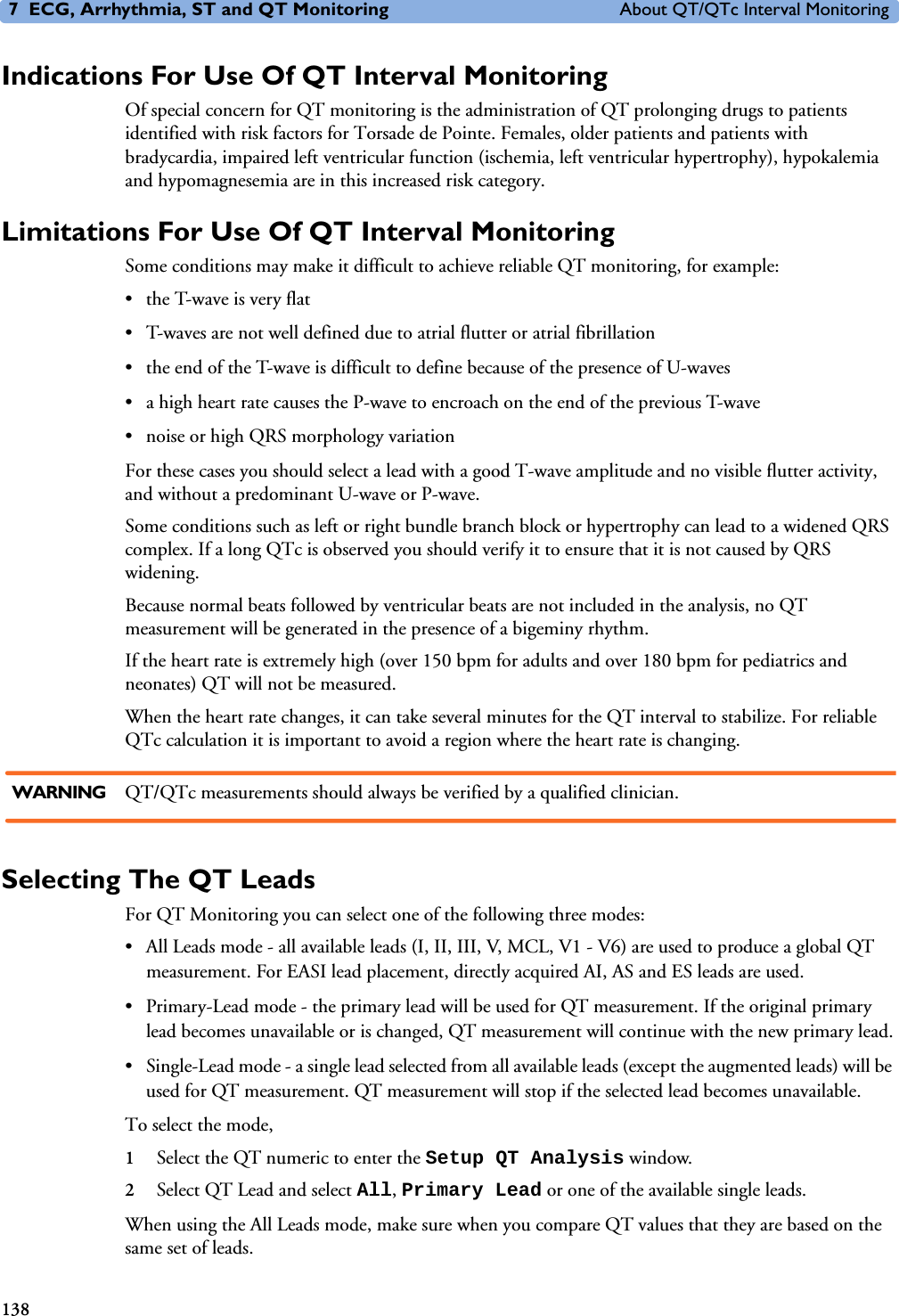
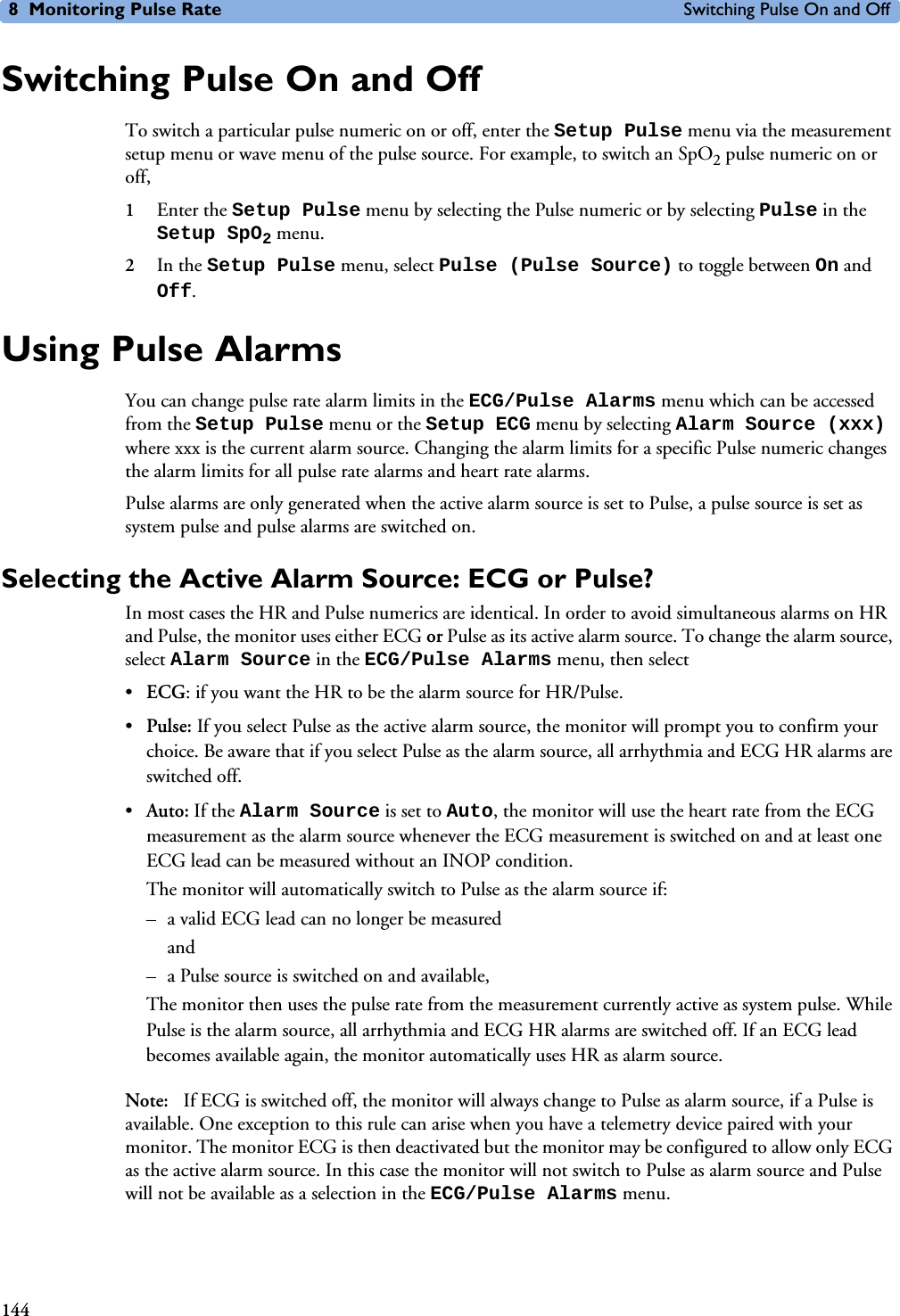
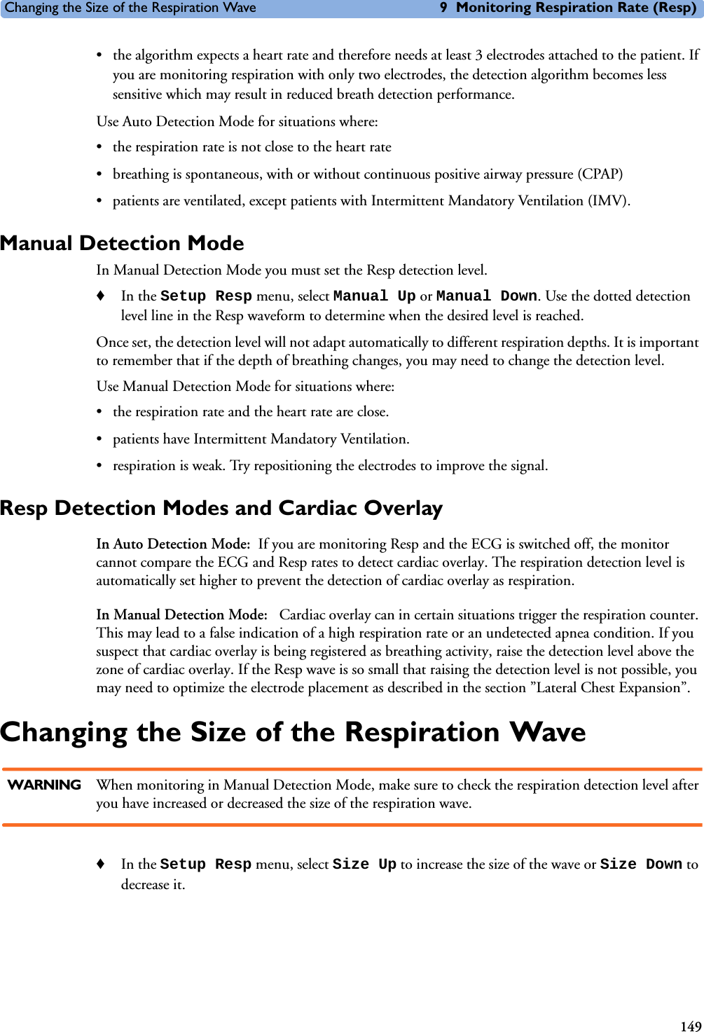
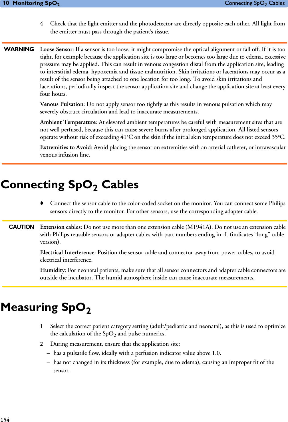
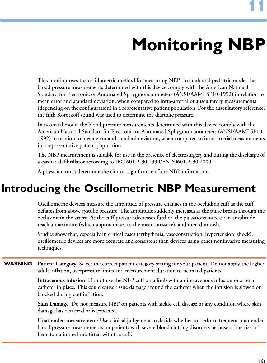
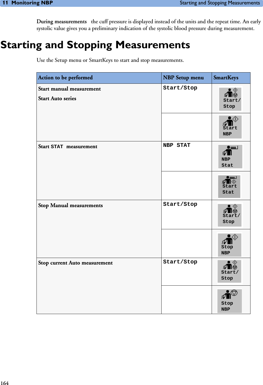
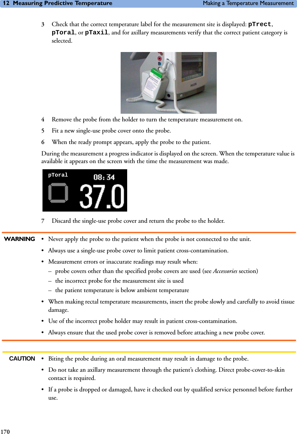
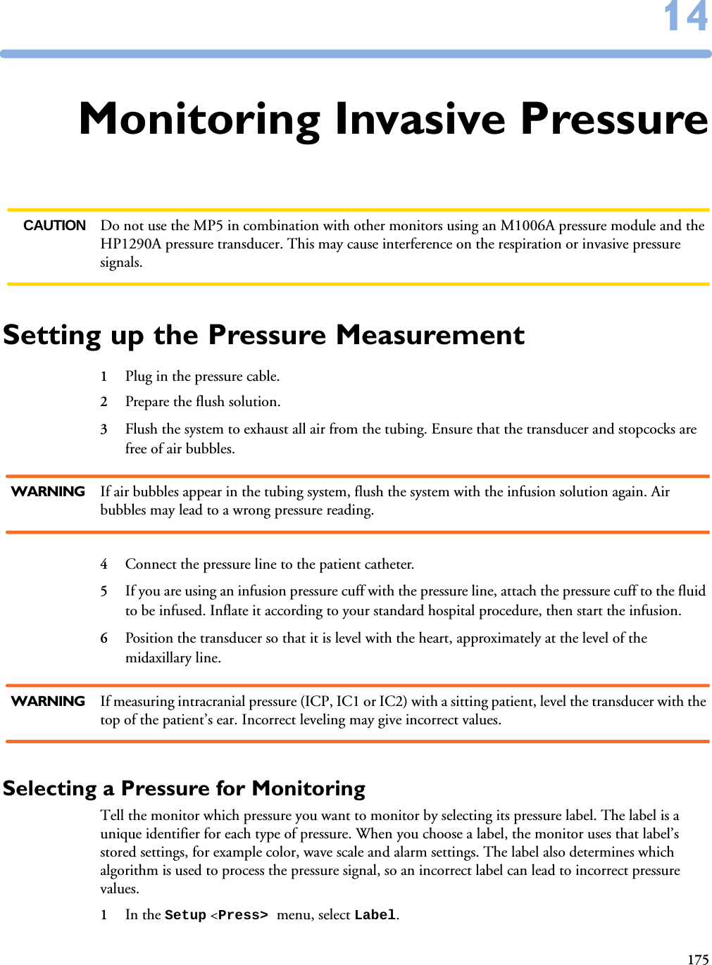
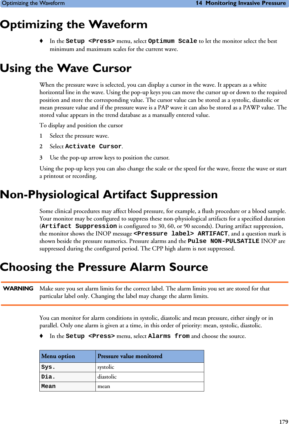
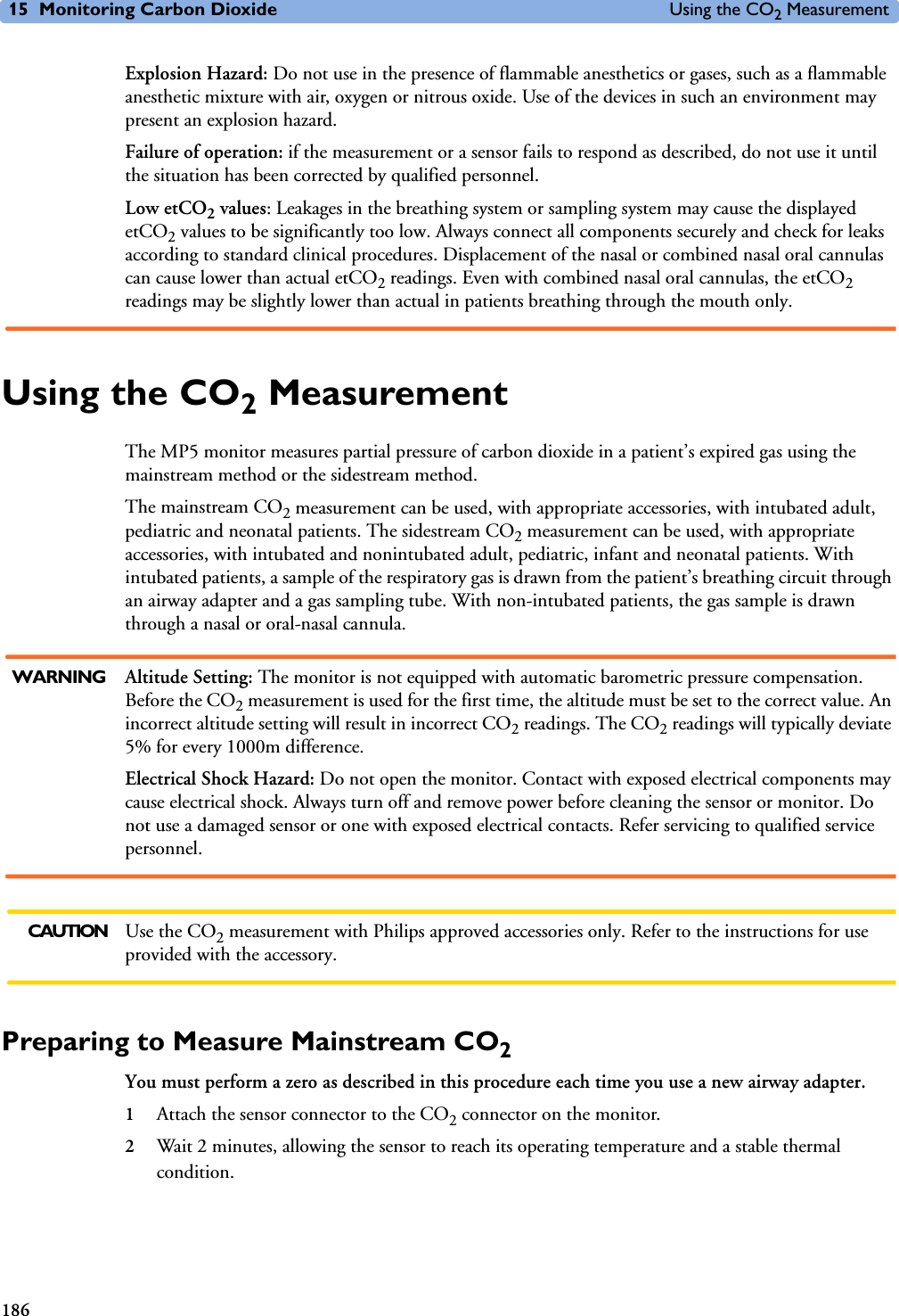
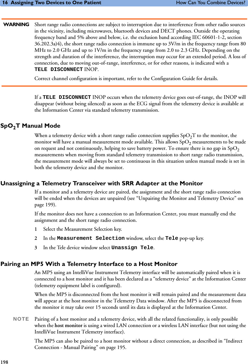
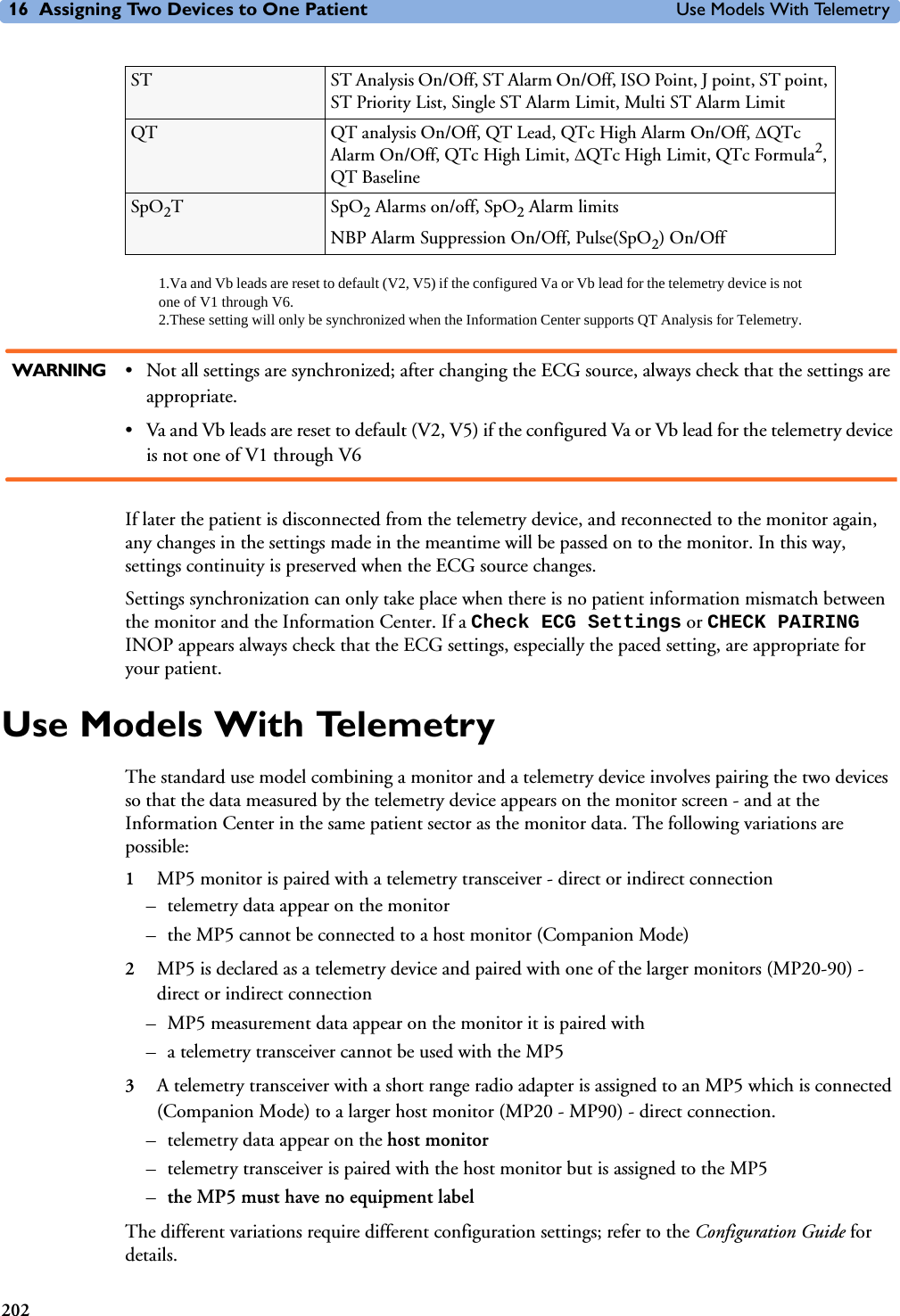
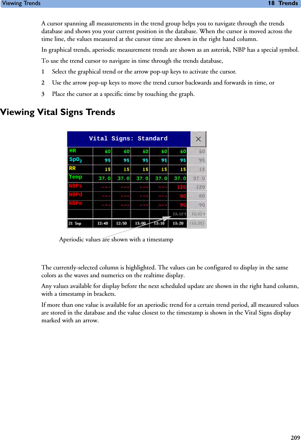
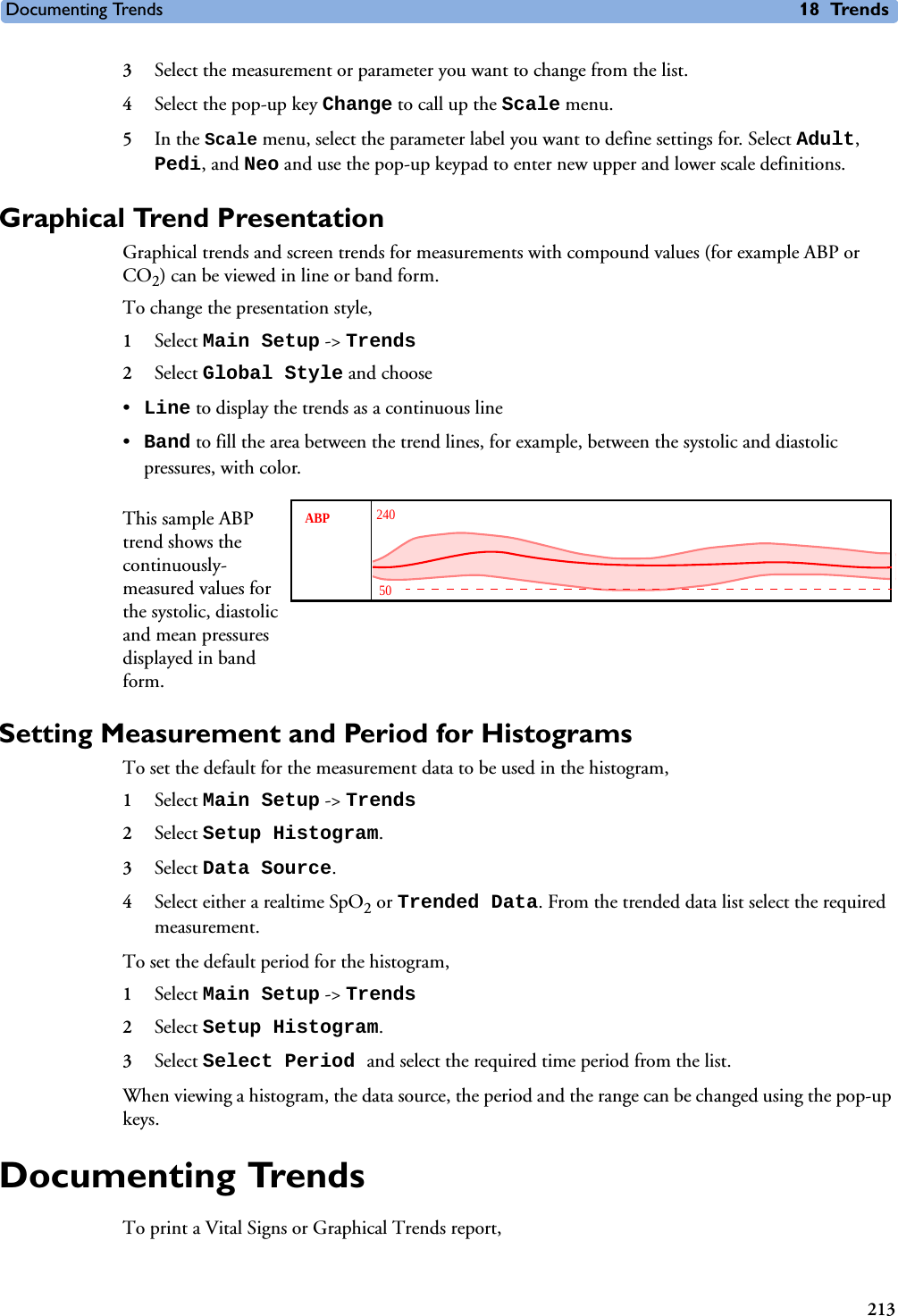
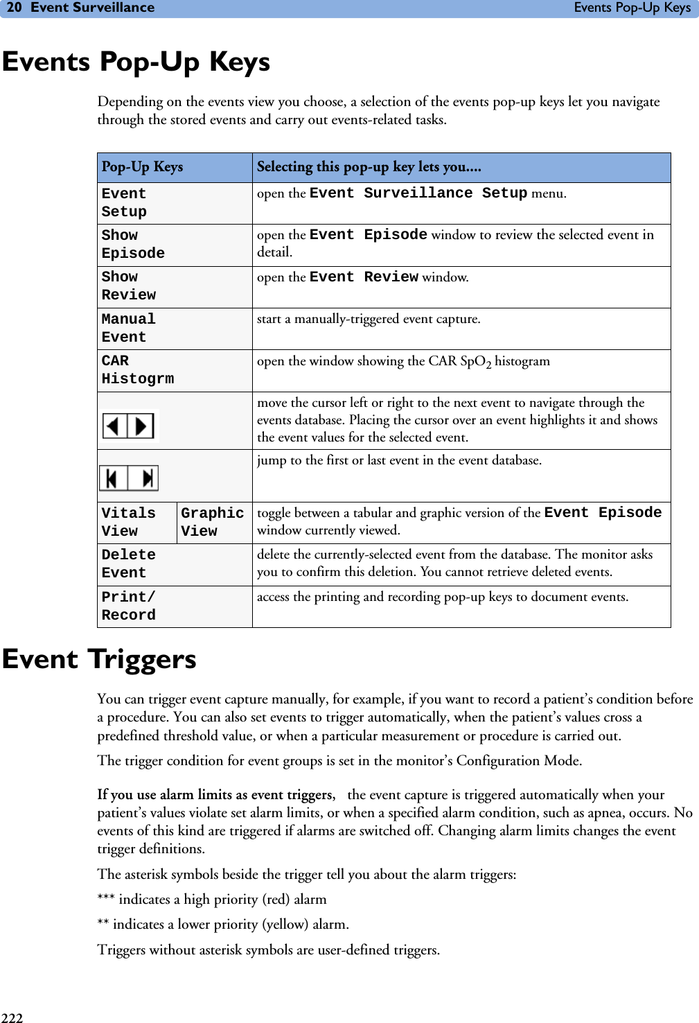
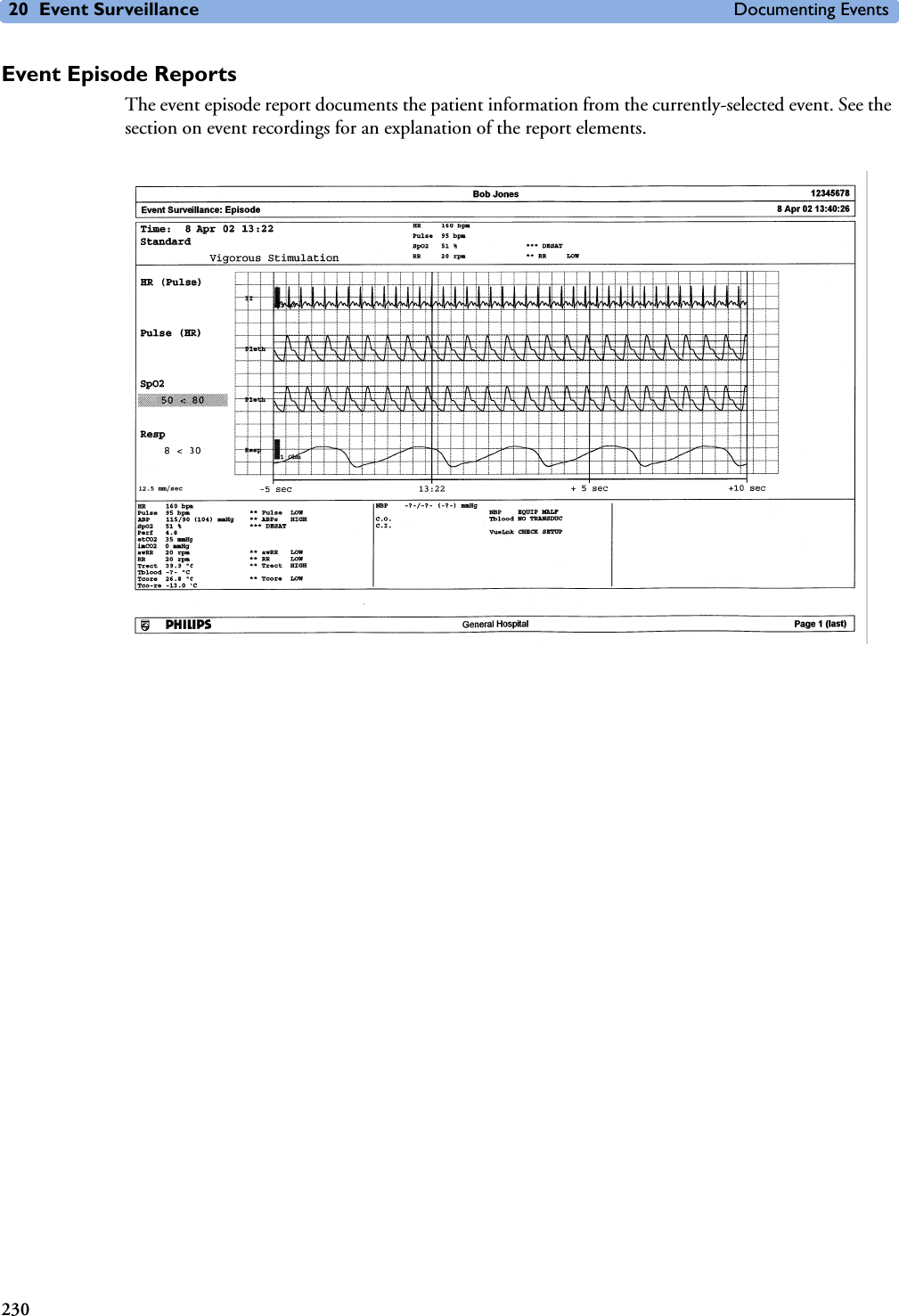
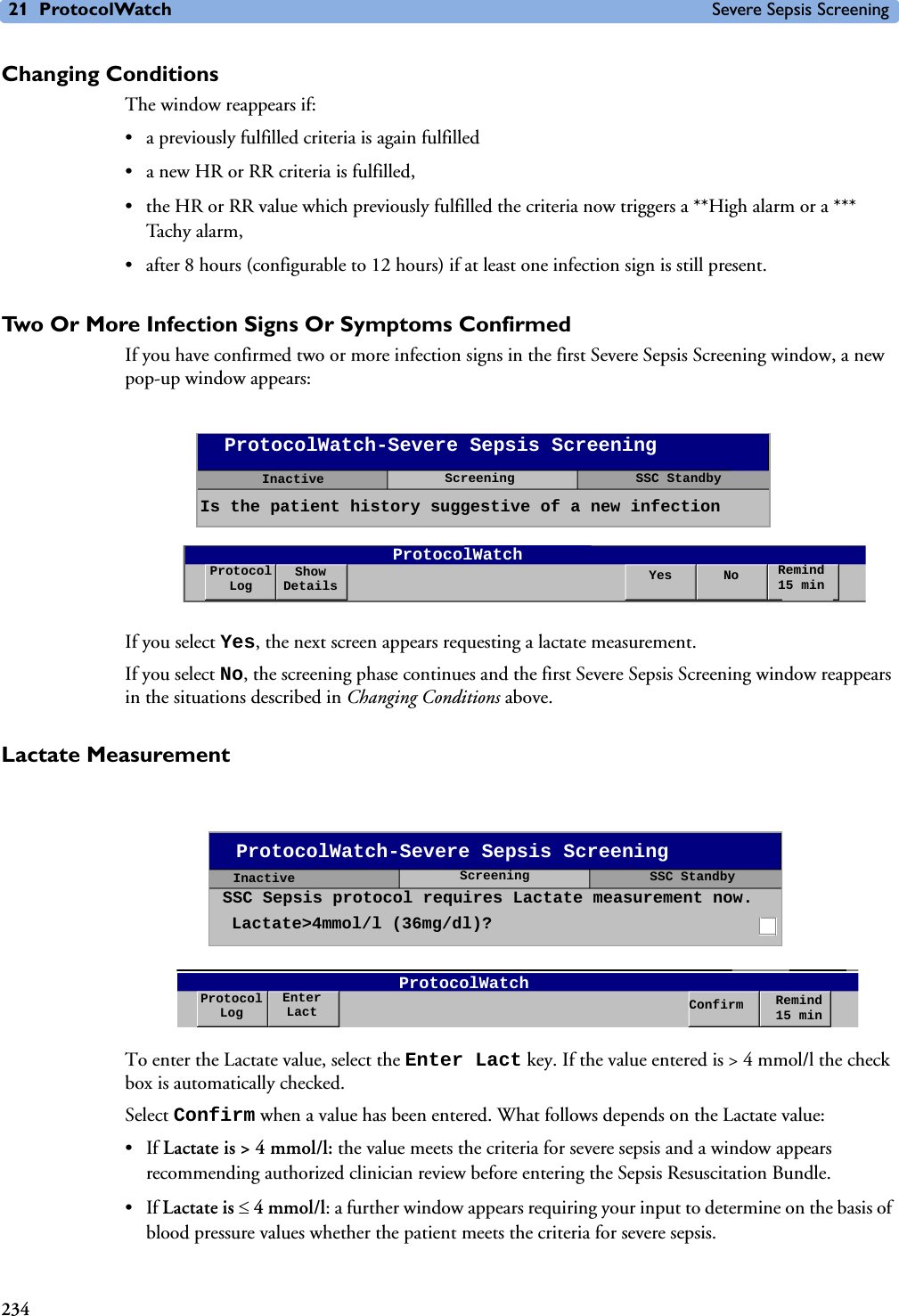
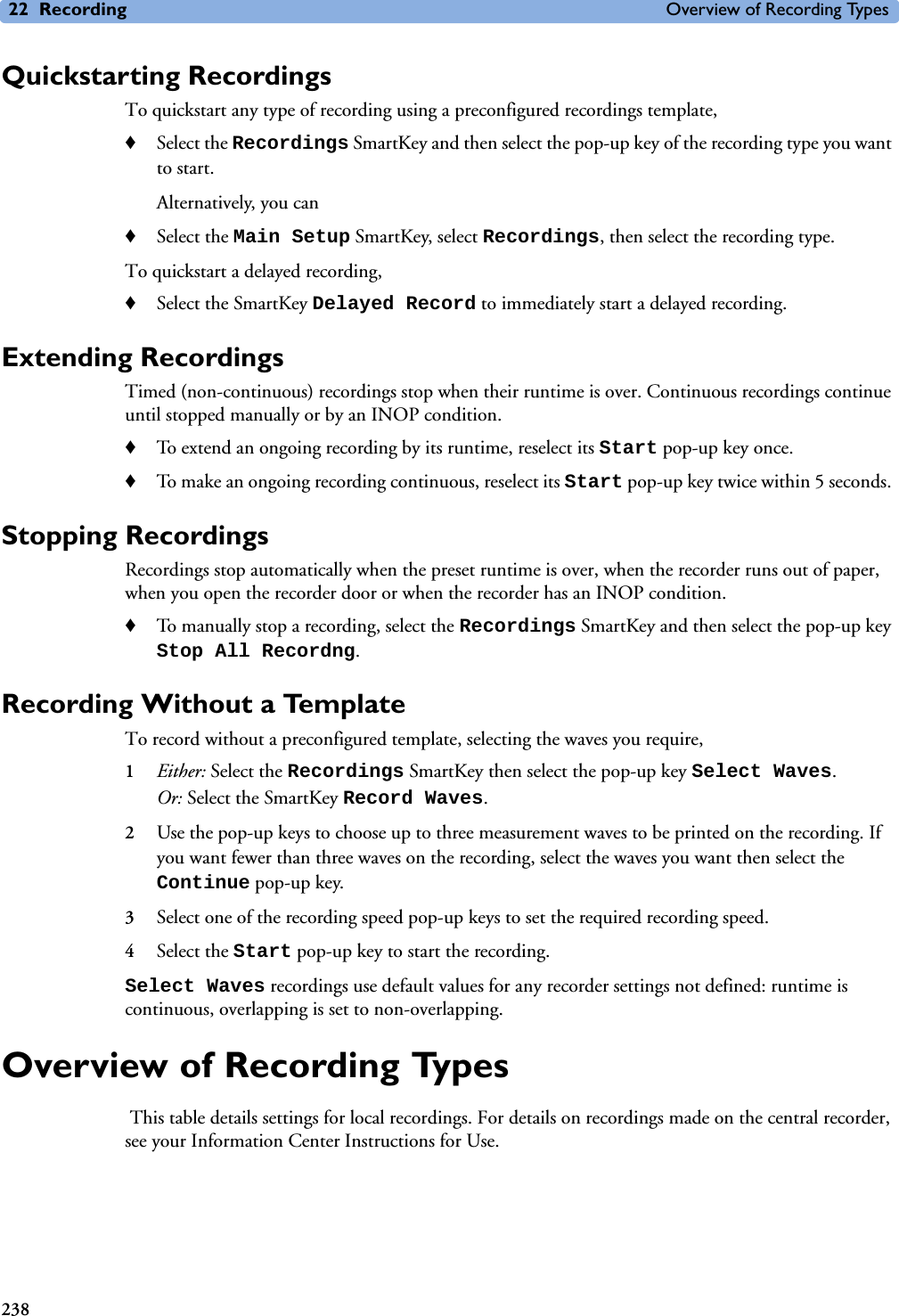
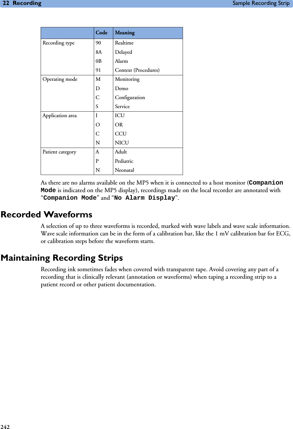
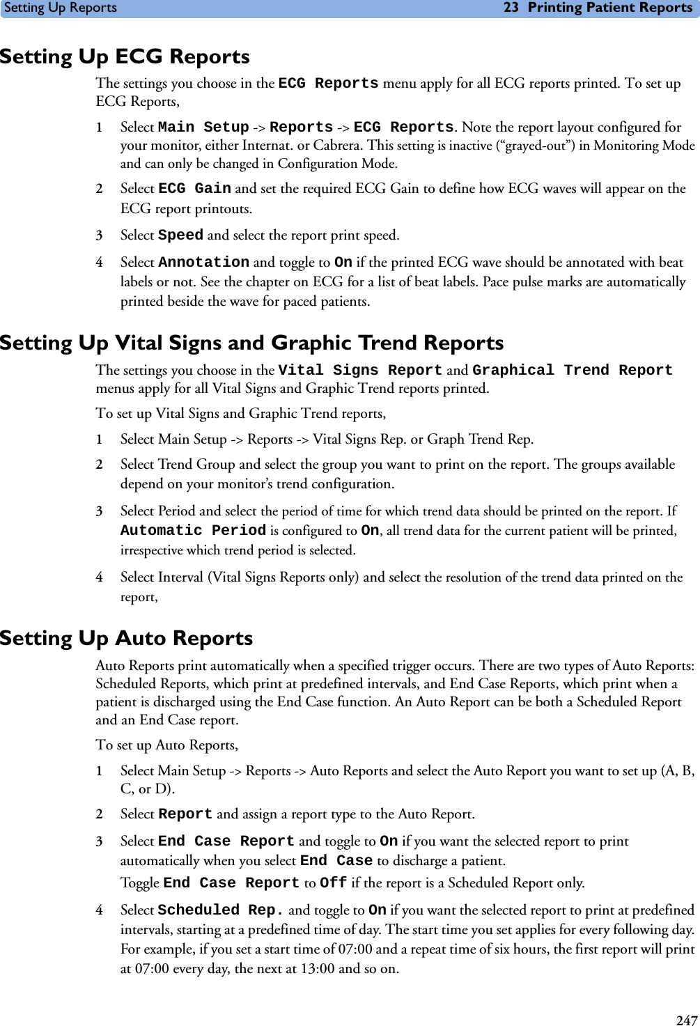
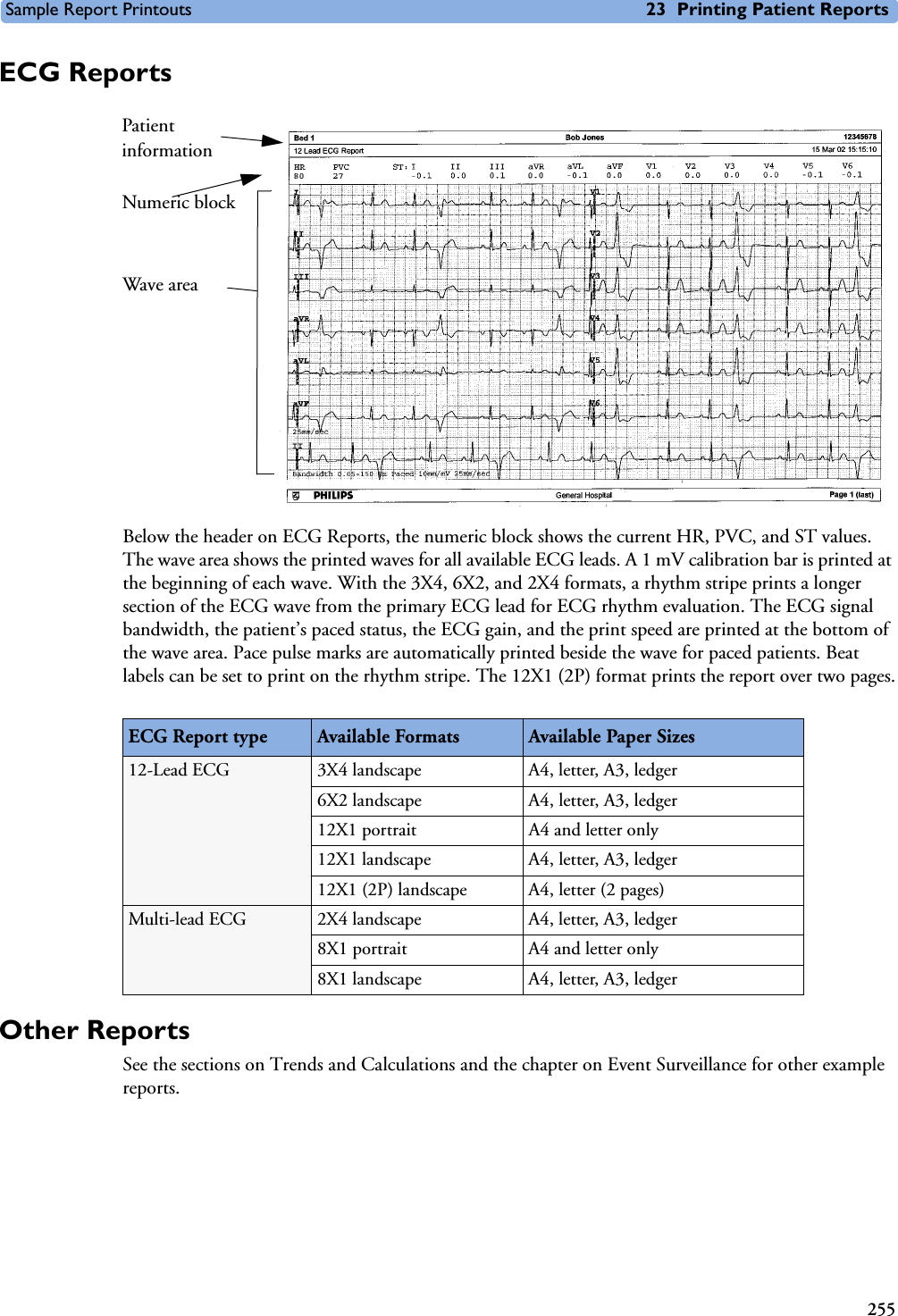
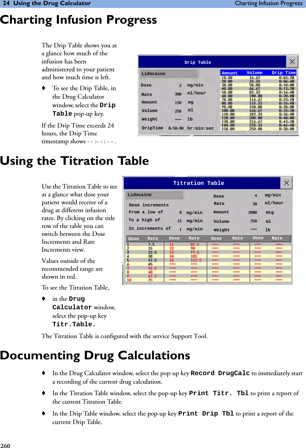
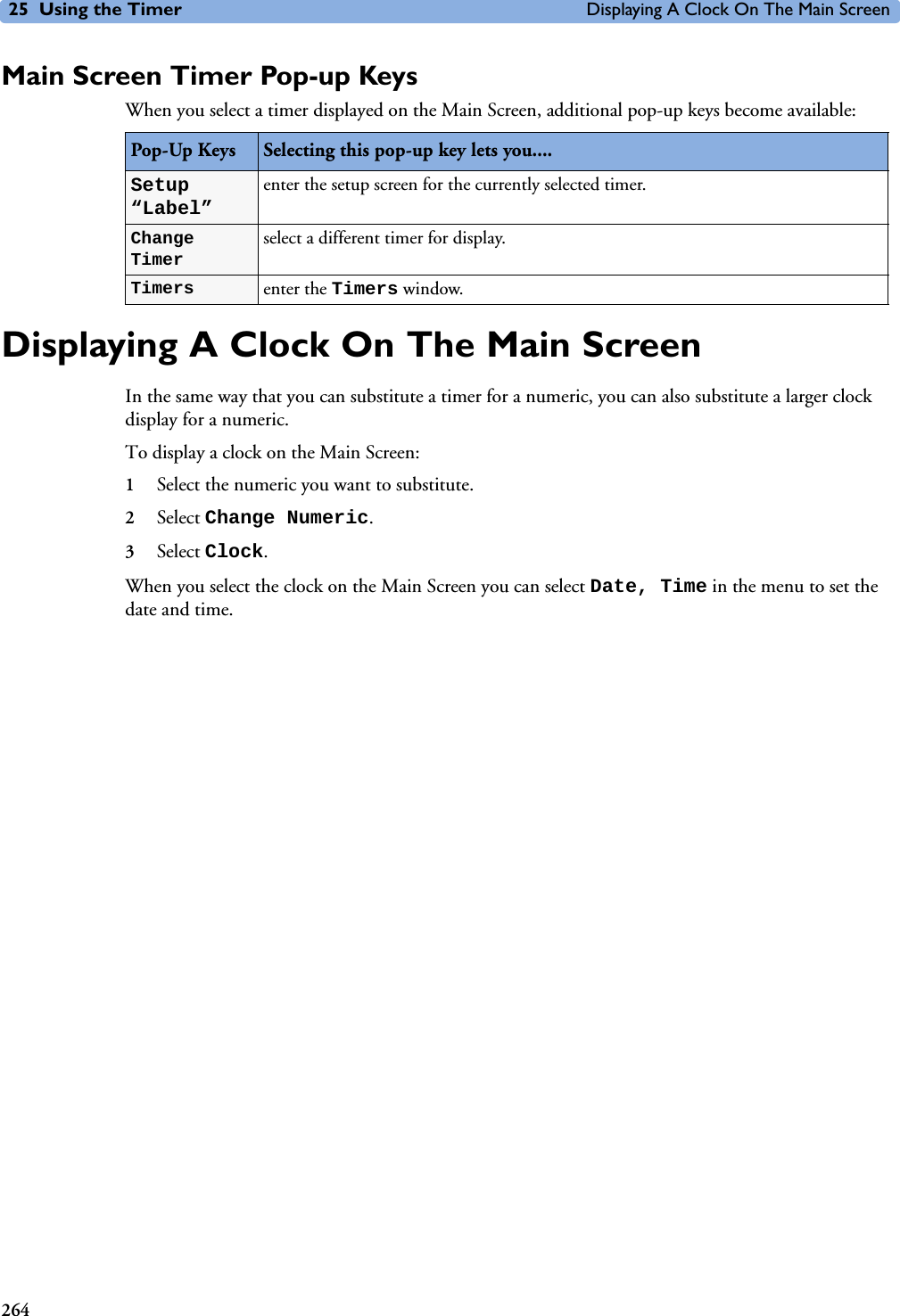
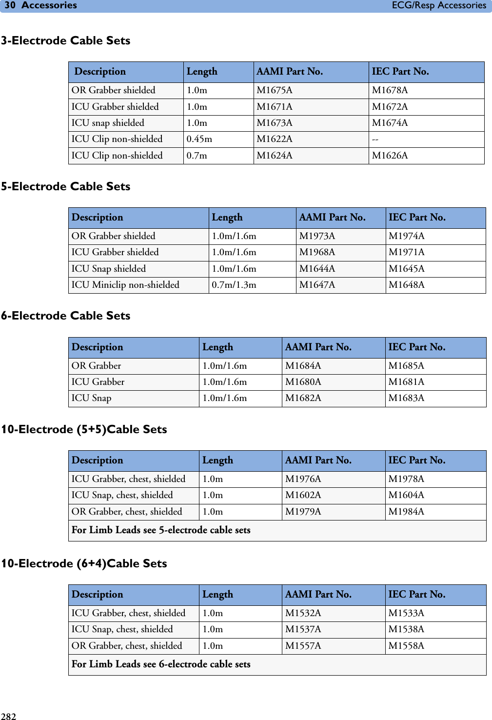
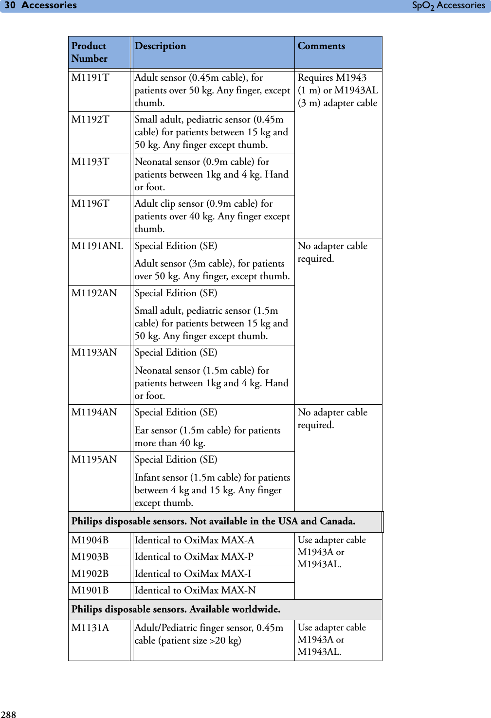
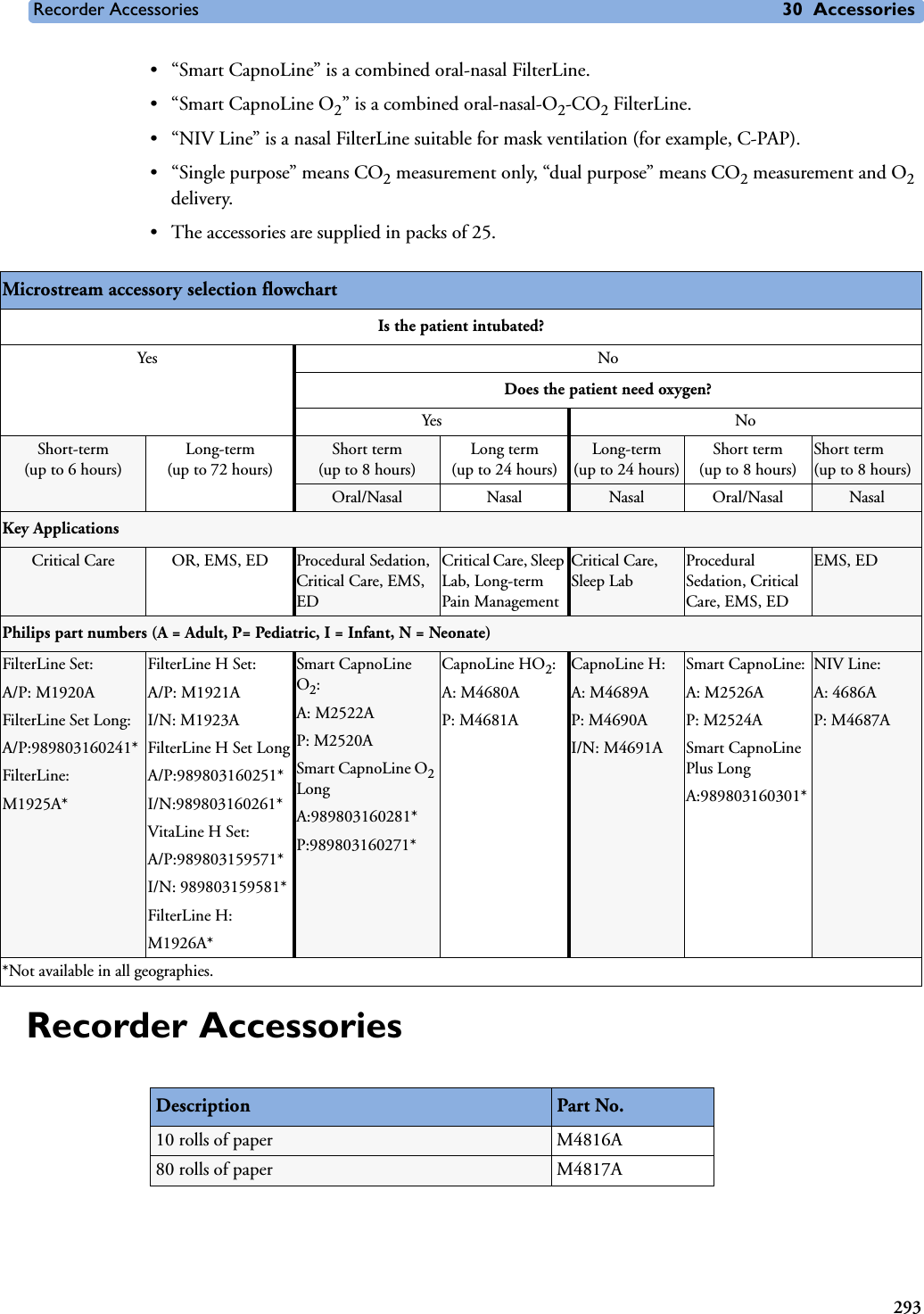
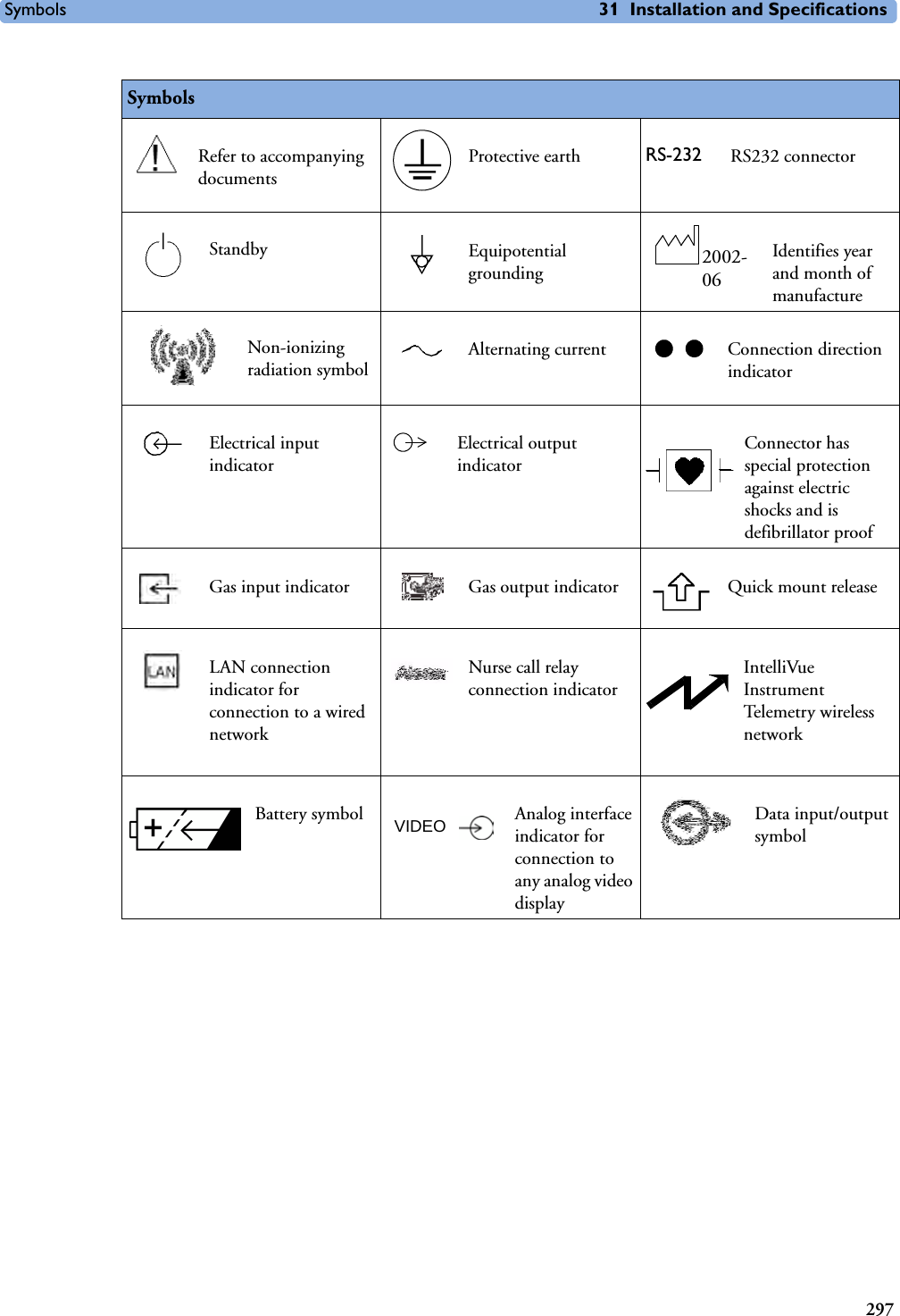
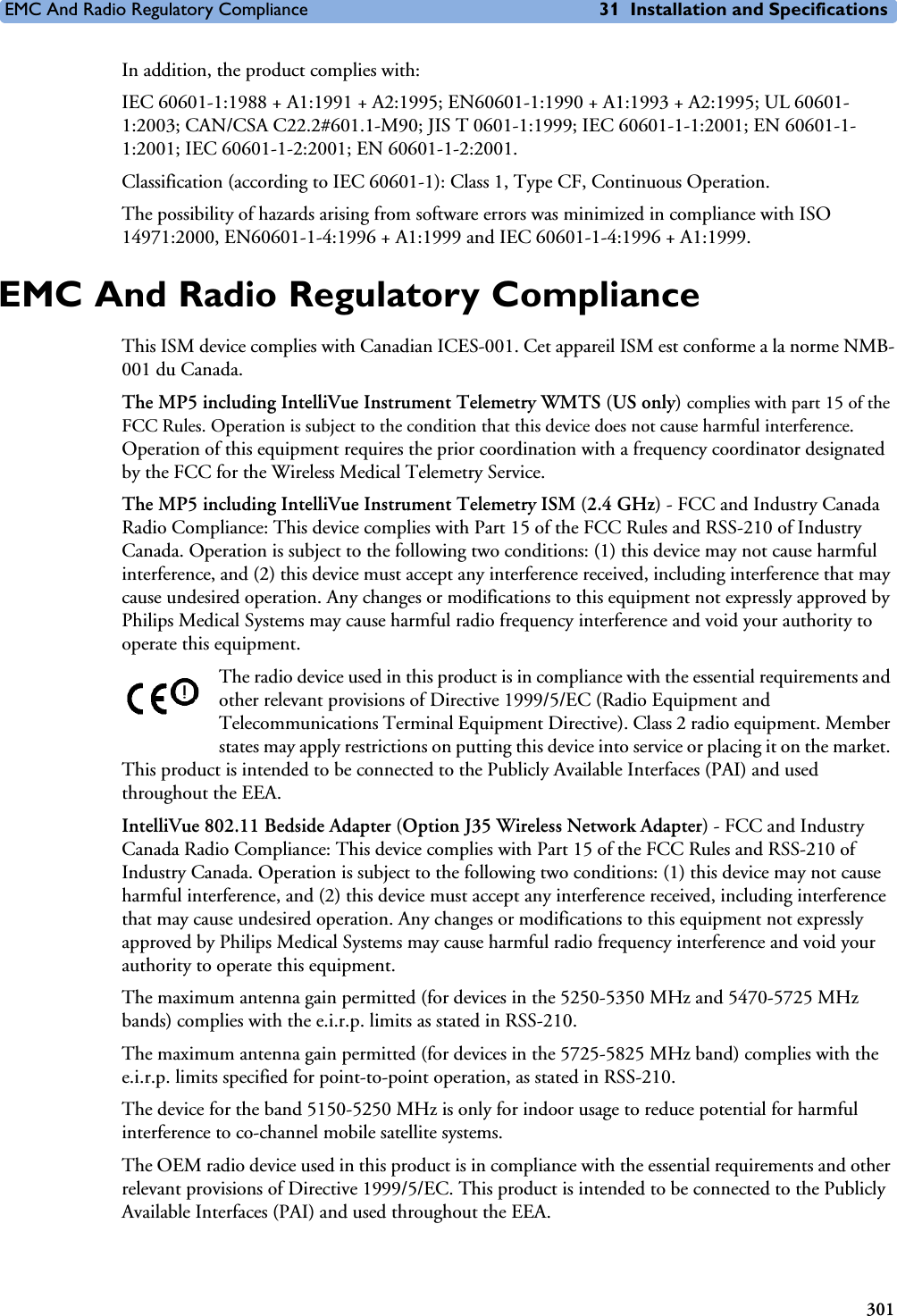
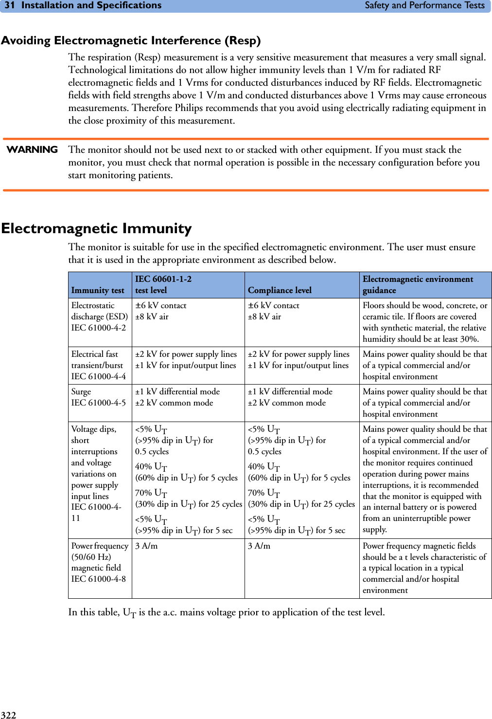
![5 Patient Alarms and INOPs Technical Alarm Messages (INOPs)82<Temp label> UNPLUGGEDINOP toneTEMP A Temp measurement label has been deactivated, either by unplugging a module, or by deactivating the label in the Measurement Selection window. The measurement automatically disappears from the display. To switch the measurement on again, either replug the module or reactivate the measurement label in the Measurement Selection window.<Temp label> OVERRANGENumeric is replaced by -?- INOP tone.TEMP Try changing the application site of the transducer.[The temperature is less than -1C, or greater than 45C.]Tesoph INOPS TEMP See <Temp label> INOPs (under Temp).TEXT UPLOAD FAILEDINOP tone IntelliBridge Incoming text from the IntelliBridge modules exceeds the maximum limit. Try unplugging one of the IntelliBridge modules. If the INOP occurs repeatedly contact your service personnel; a software upgrade may be necessary. TimeExpired:<timer label>INOP toneMonitor The time has expired for the timer indicated in the INOP text. Clearing the timer clears the INOP. Tnaso INOPS TEMP See <Temp label> INOPs (under Temp).Trect INOPS TEMP See <Temp label> INOPs (under Temp).Tskin INOPS TEMP See <Temp label> INOPs (under Temp).Ttymp INOPS TEMP See <Temp label> INOPs (under Temp)Tven INOPS TEMP See <Temp label> INOPs (under Temp).Tvesic INOPS TEMP See <Temp label> INOPs (under Temp)UAP INOPS PRESS See <Pressure label> INOPS (under Pressure).Unsupported LANINOP toneMonitor There is a problem with the communication to the network and central monitoring is currently not possible. Check the connection. If the INOP persists, switch off the monitor and contact your service personnel.User I/F Malfunct.INOP tone.Monitor Perform a visual and functional check of all the monitor input devices. Contact your service personnel.UVP INOPS PRESS See <Pressure label> INOPS (under Pressure).V LEAD OFFNumeric is replaced by -?- for 10 seconds; INOP tone.ECG The V electrode (IEC: C electrode) has become detached from the patient or the lead set has been changed. Reattach the electrode or select New Lead Setup in the Setup ECG menu to confirm the new lead set. <VueLink option> CHK CABLEINOP tone.VueLink No cable or the wrong cable connected to the VueLink module, or incorrect device selected. Silencing this INOP switches the measurement off. VueLink INOP abbreviations may differ slightly depending on the device category.<VueLink option> CHK CONF.INOP tone.VueLink The wrong external device has been selected on the VueLink module, or the external device has not been correctly setup, or the wrong cable has been used to connect the device to the VueLink module.VueLink INOP abbreviations may differ slightly depending on the device category.INOP Message, Indication Source What to do](https://usermanual.wiki/Philips-Medical-Systems-North-America/SRRBV1.User-Manual-MP5-and-MP5T/User-Guide-1044633-Page-92.png)

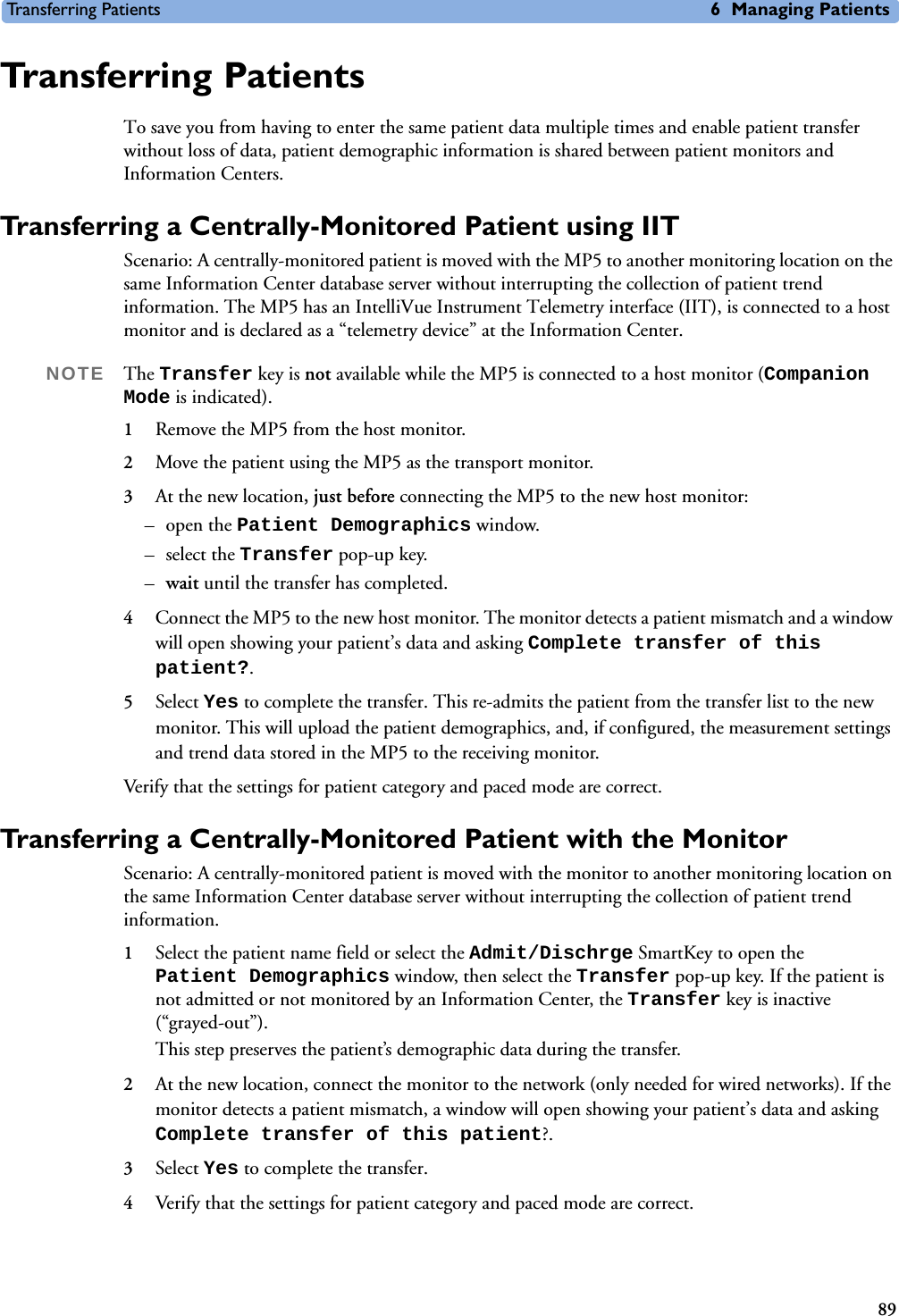
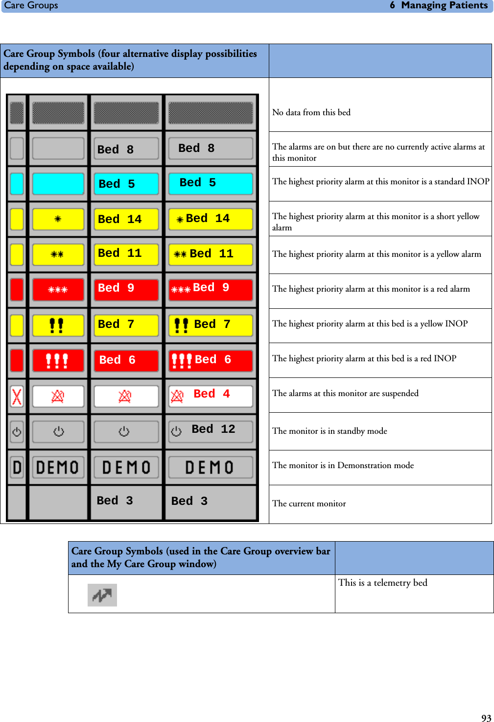


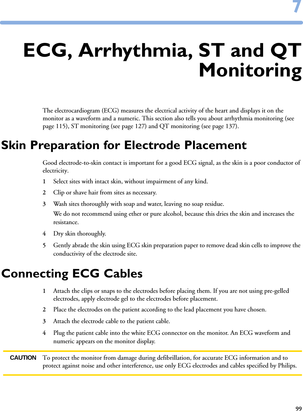
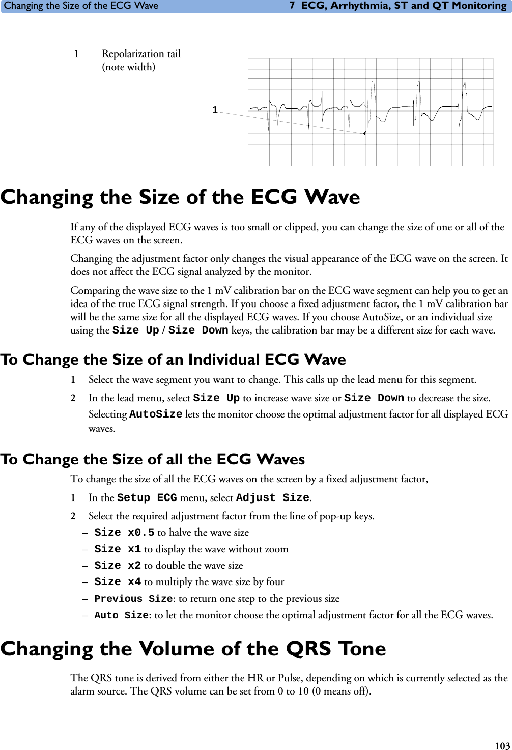
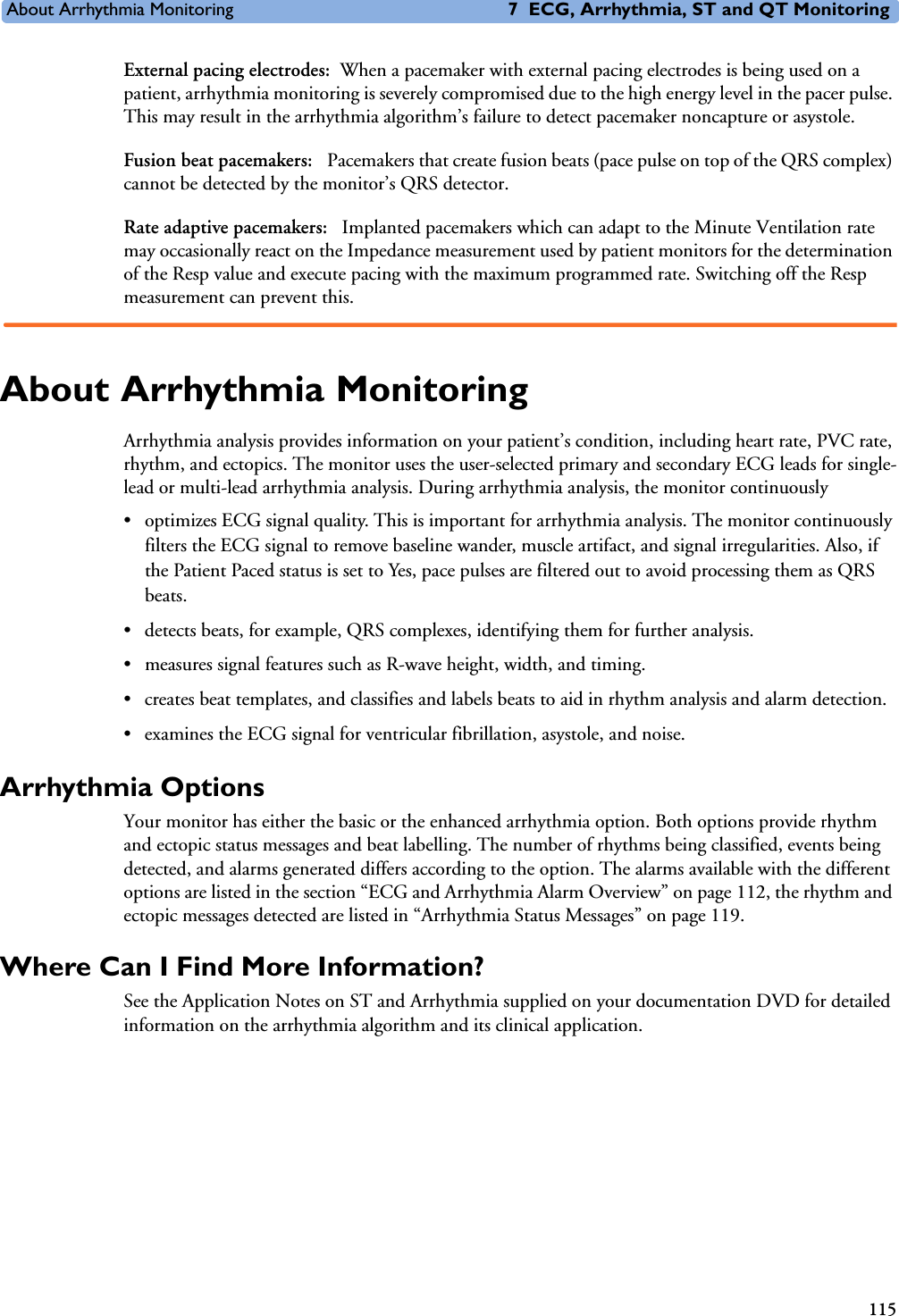
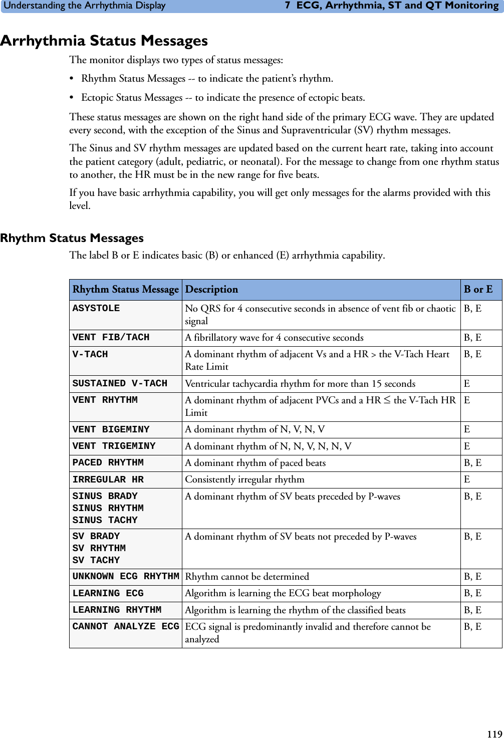
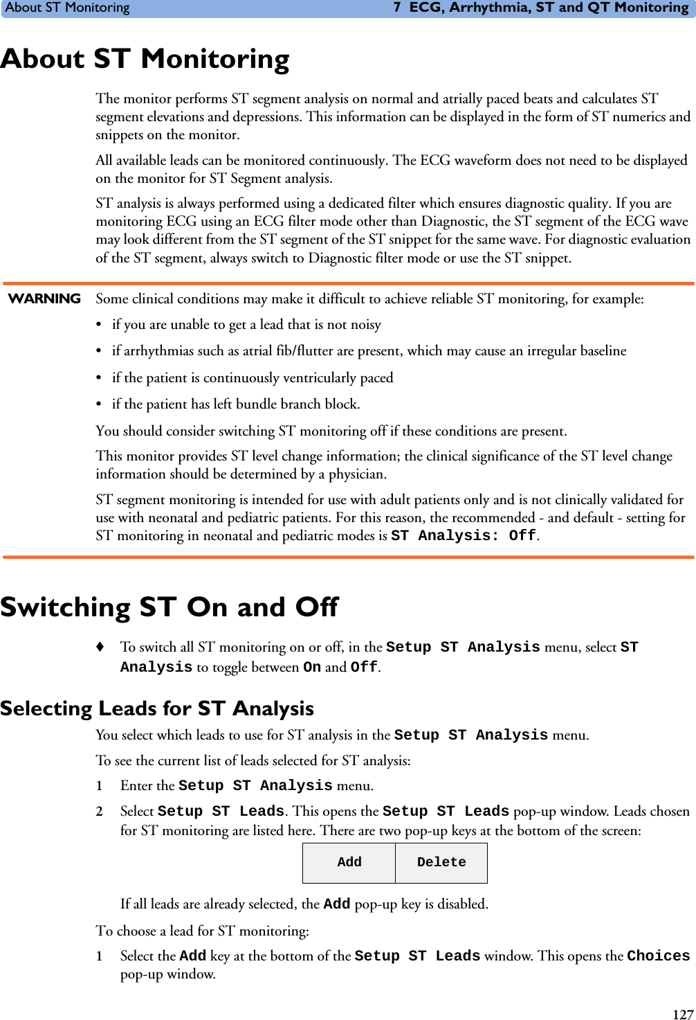
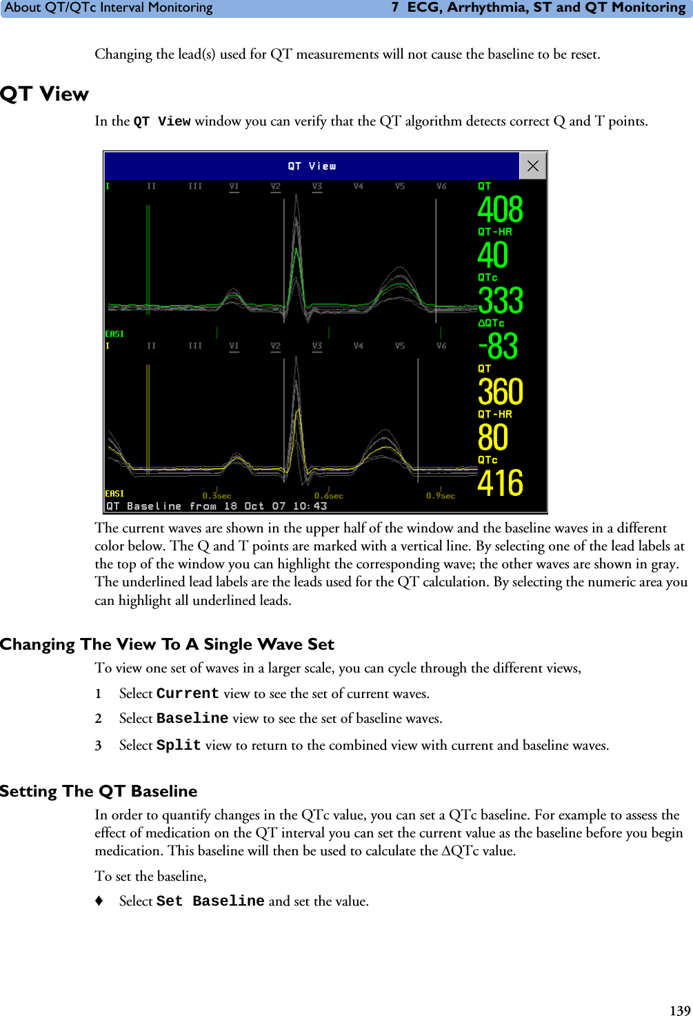


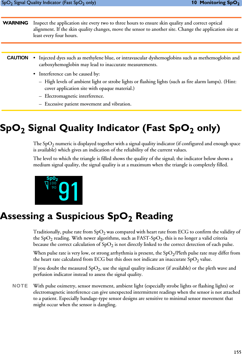


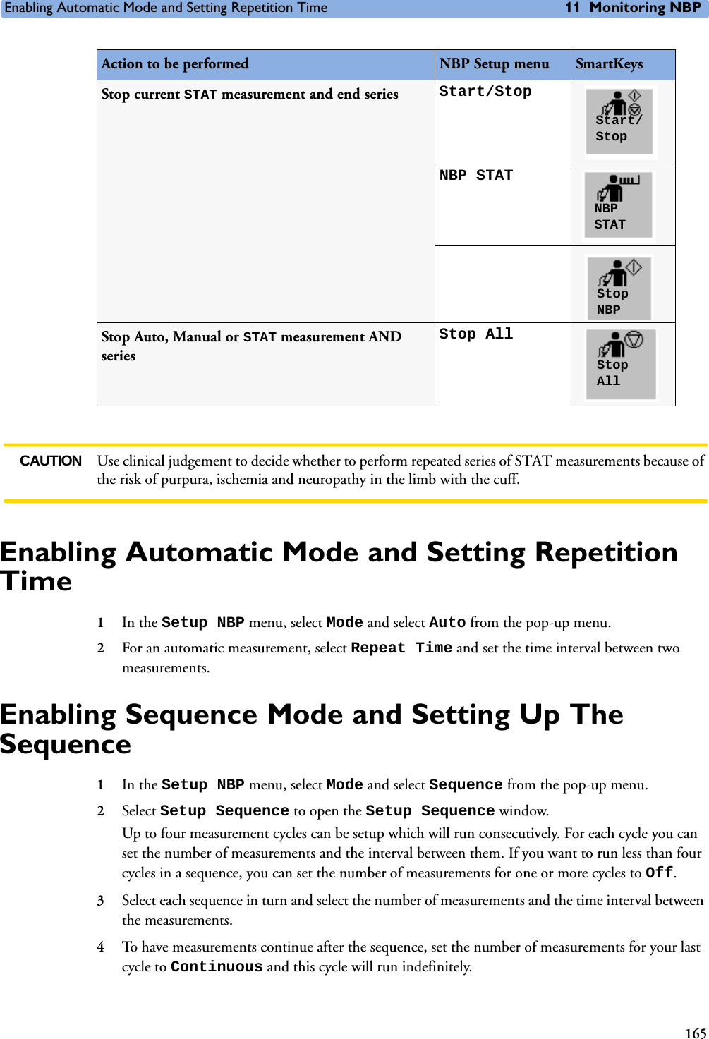


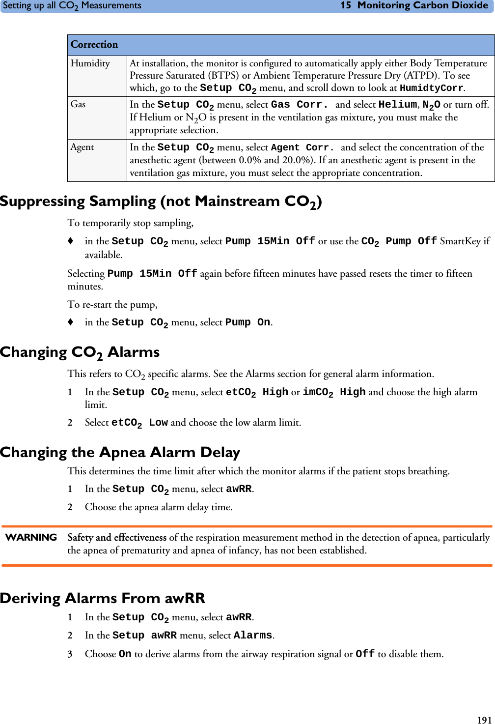


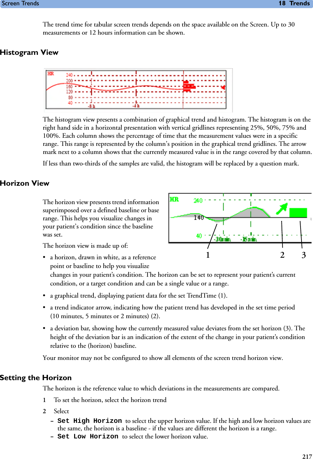

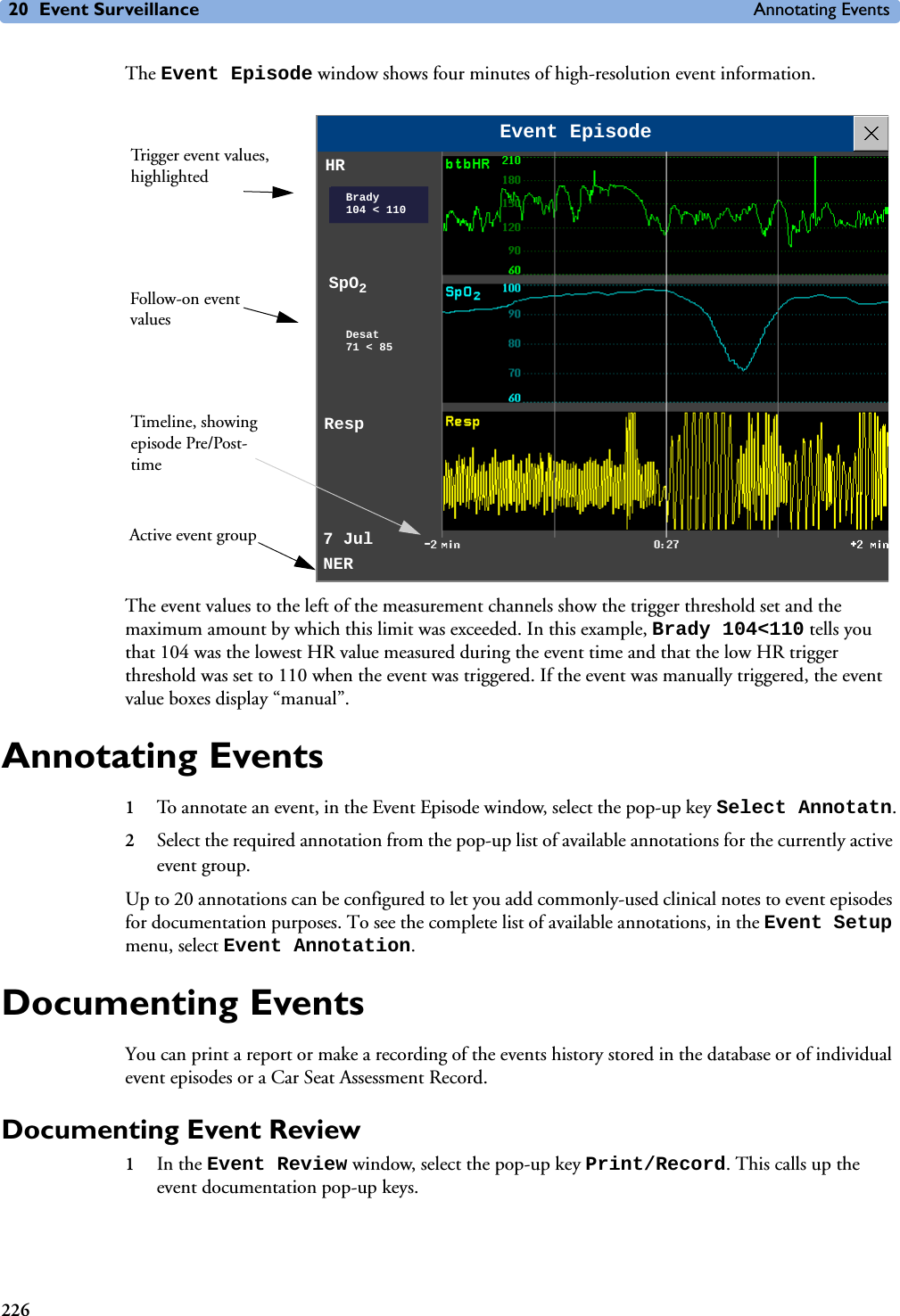

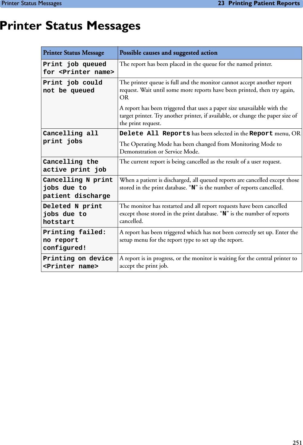


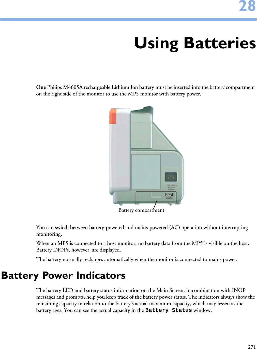
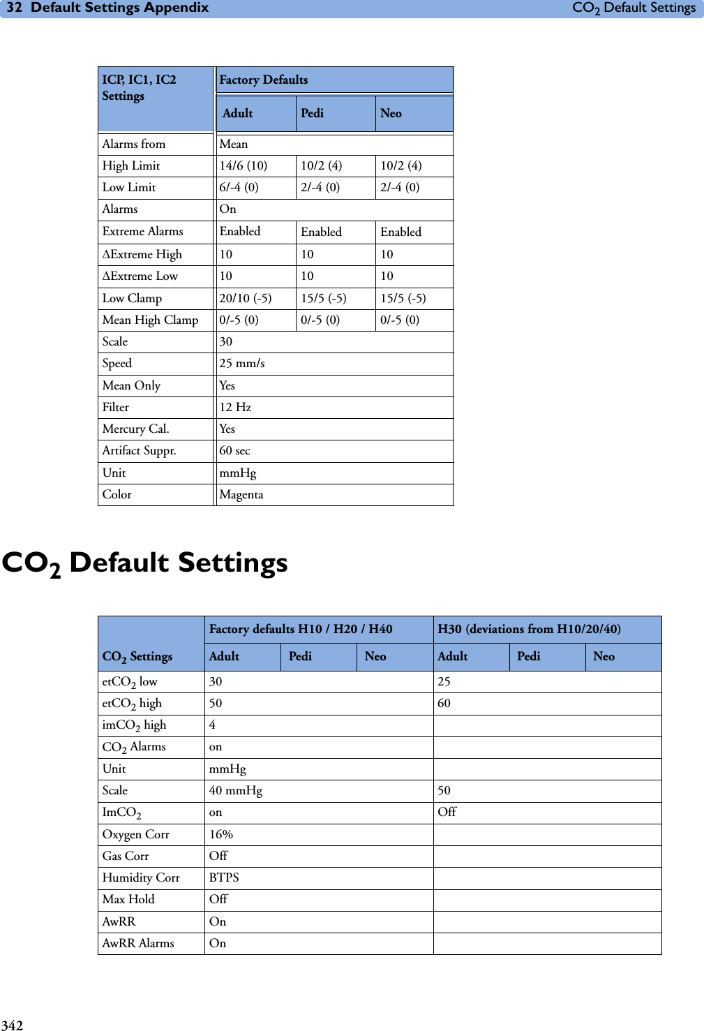
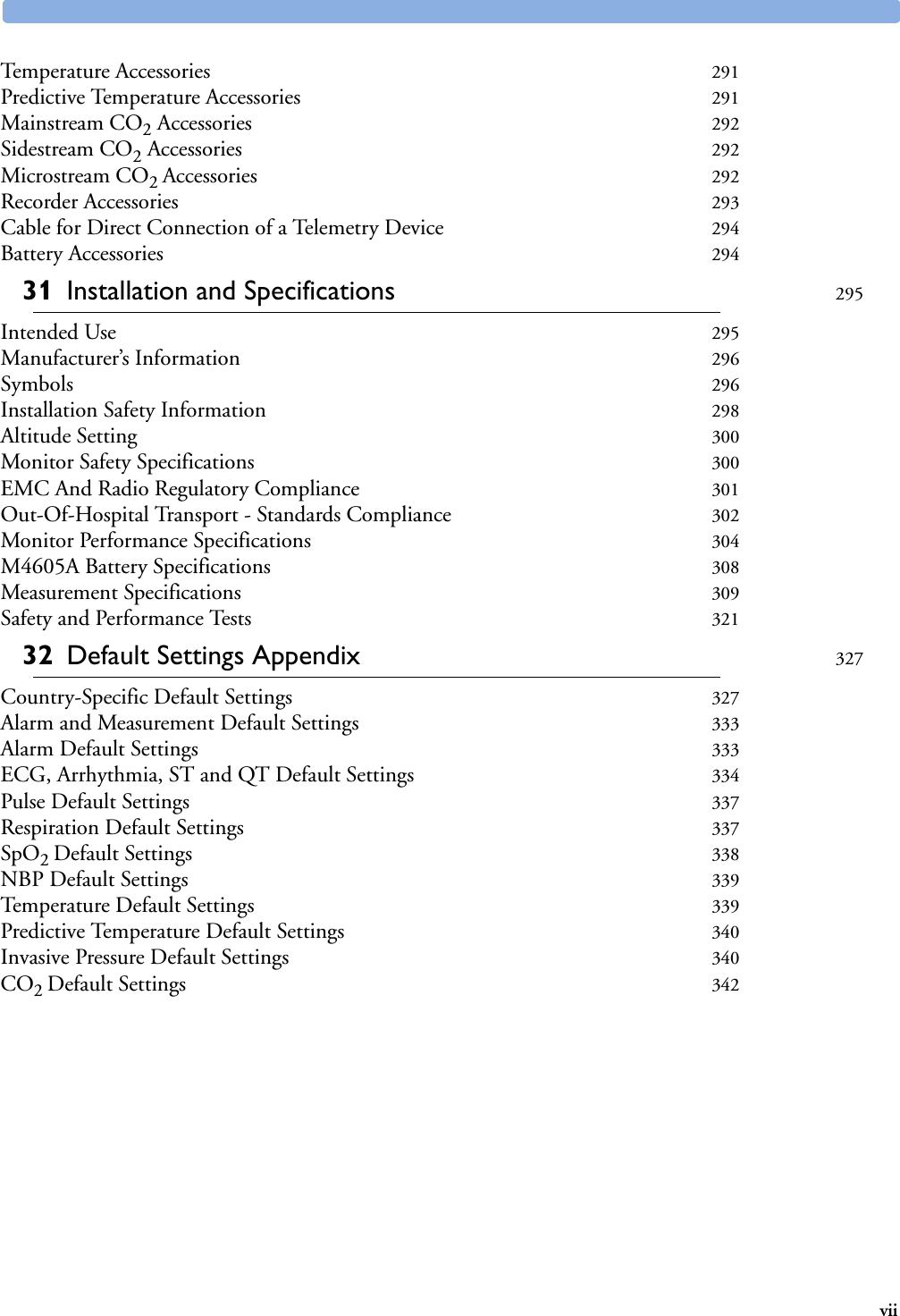
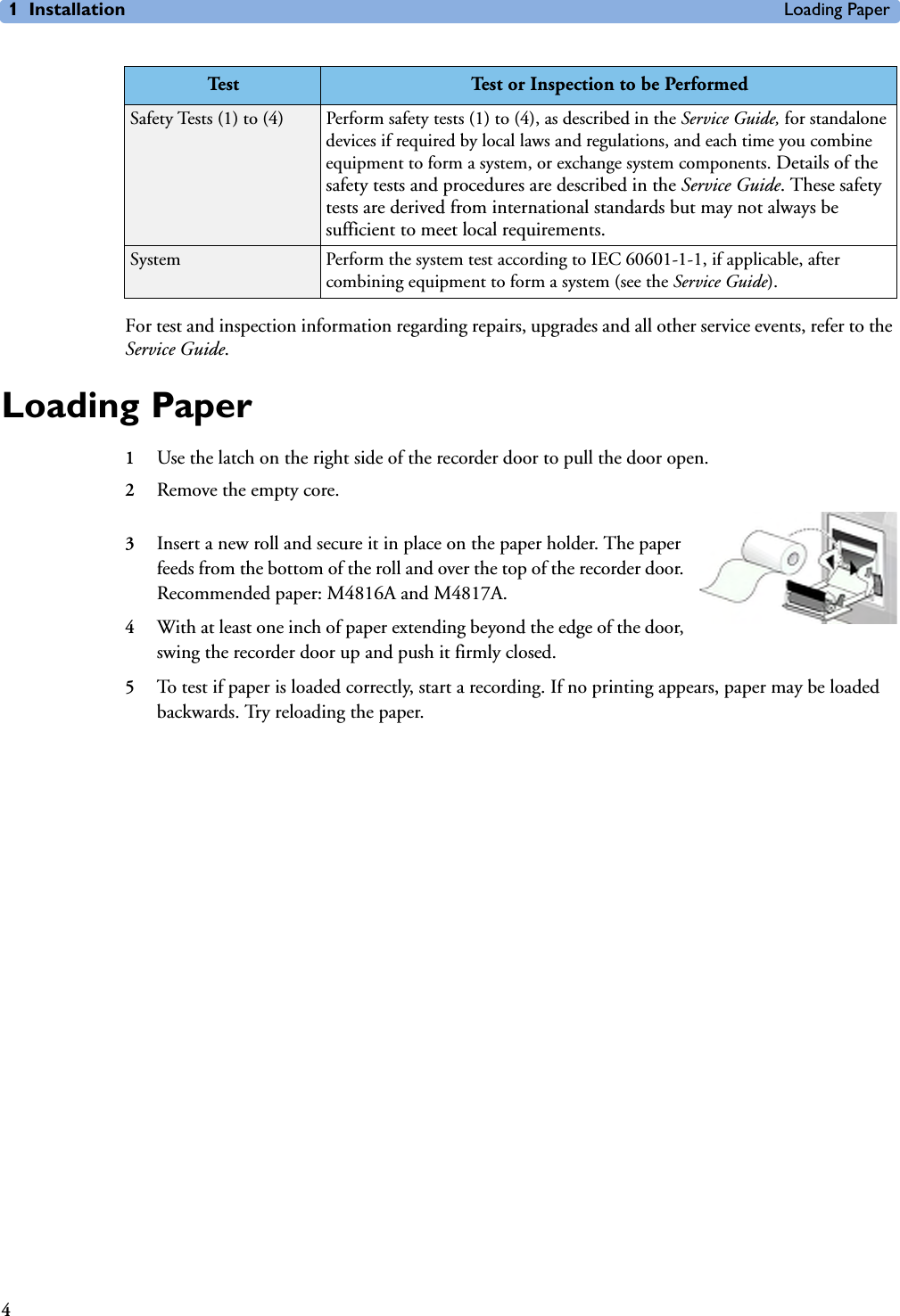
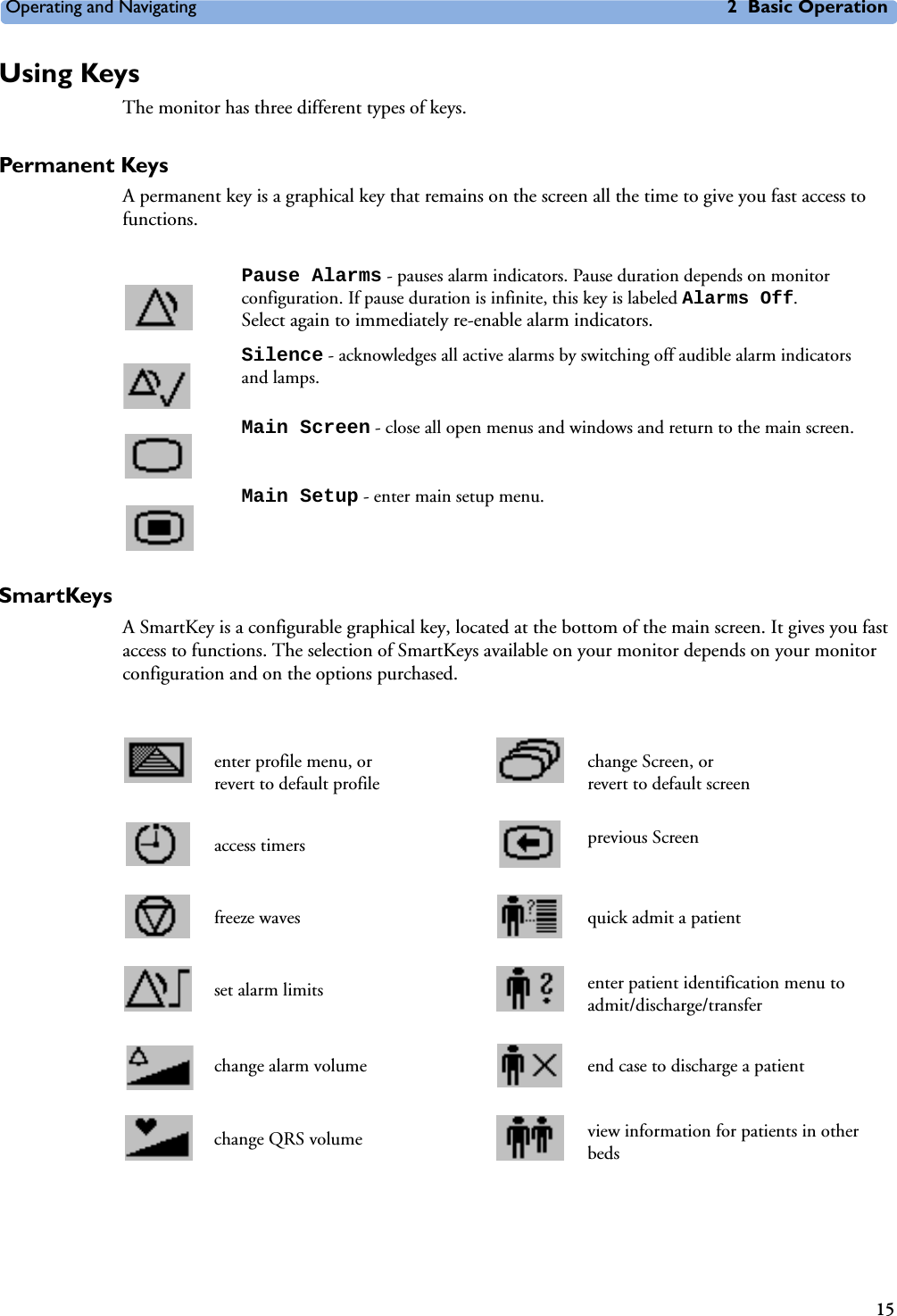
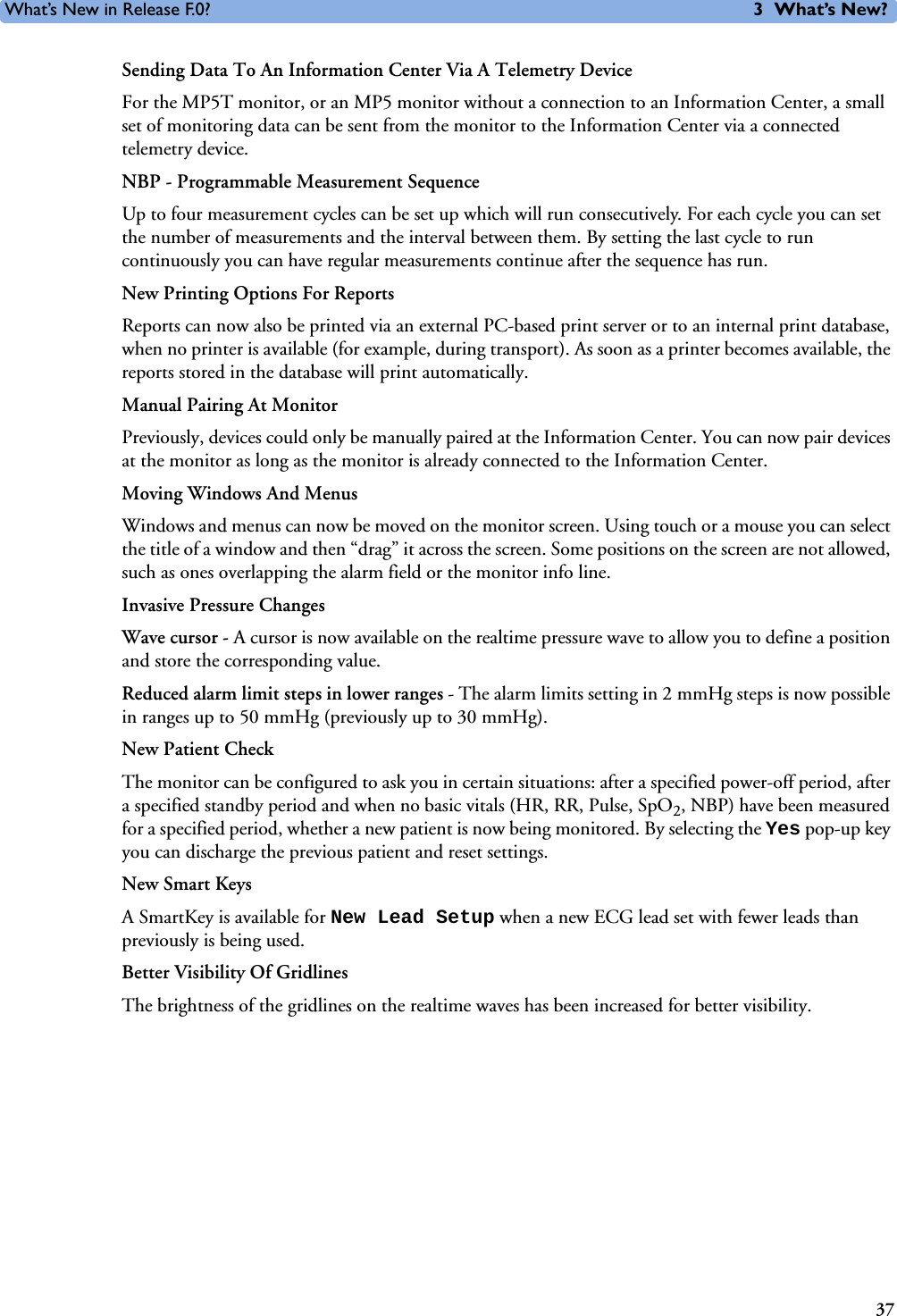
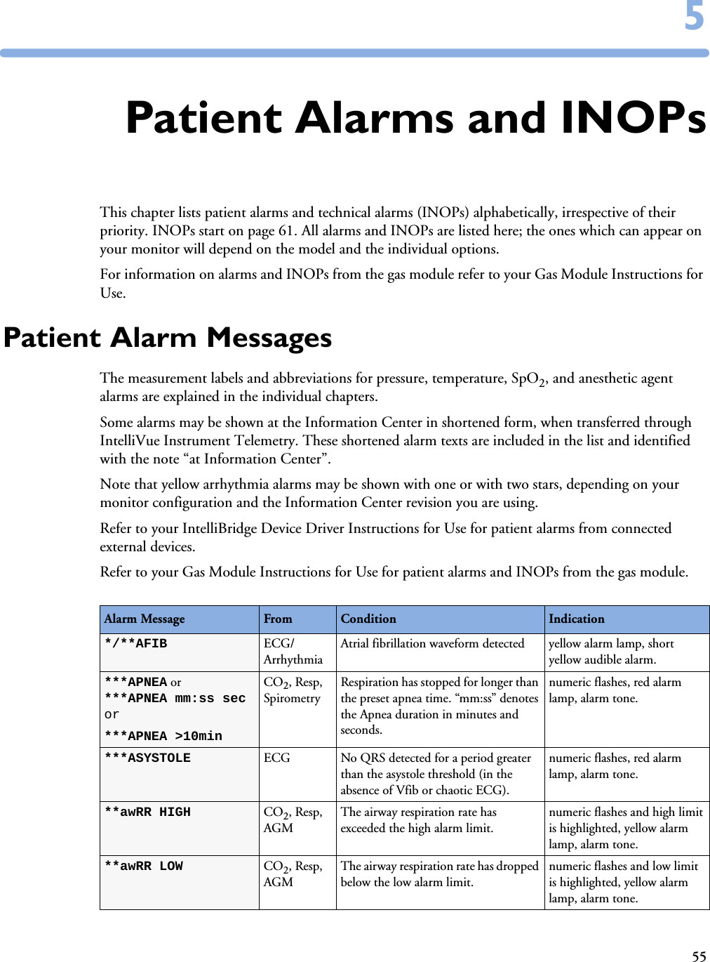
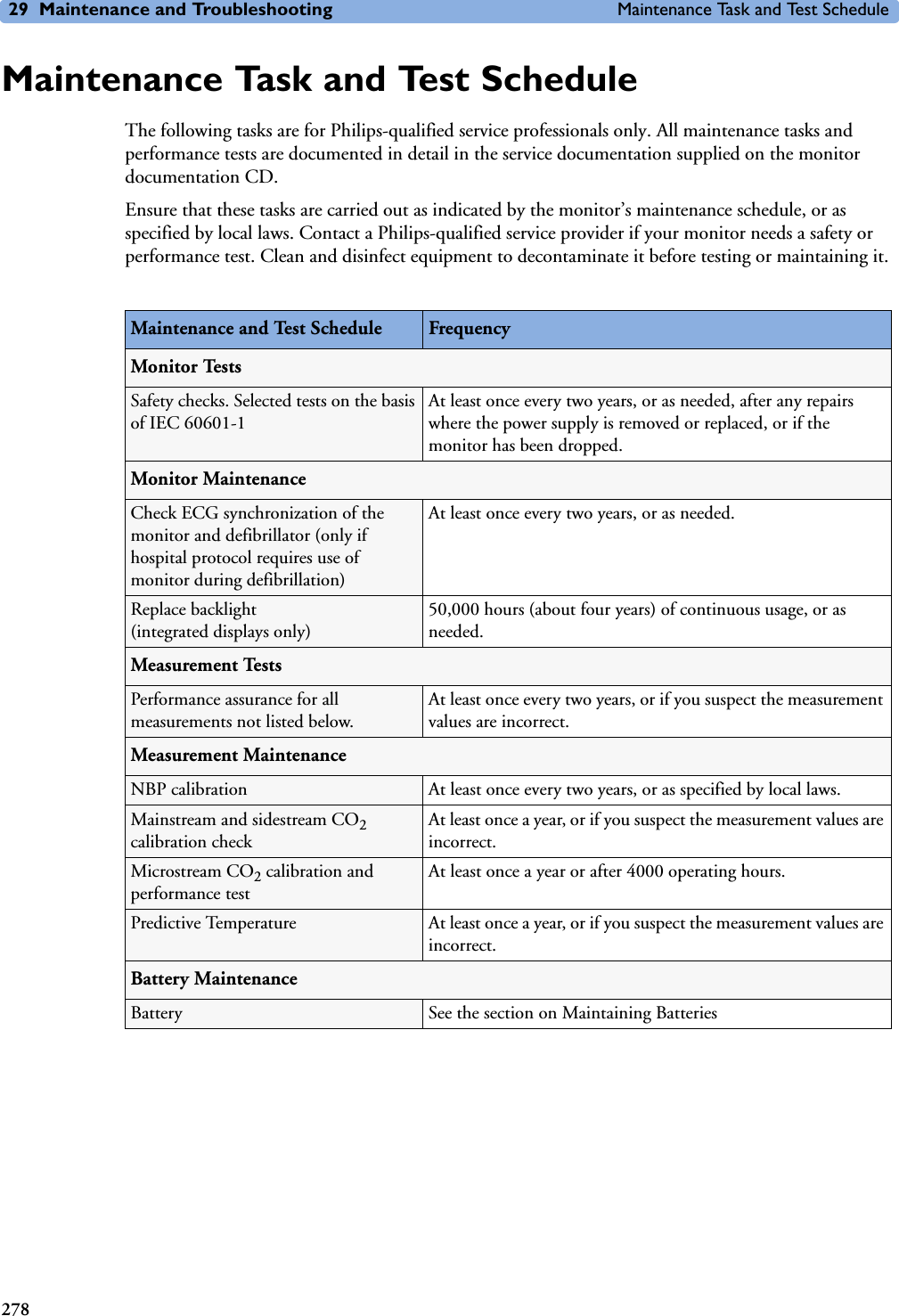
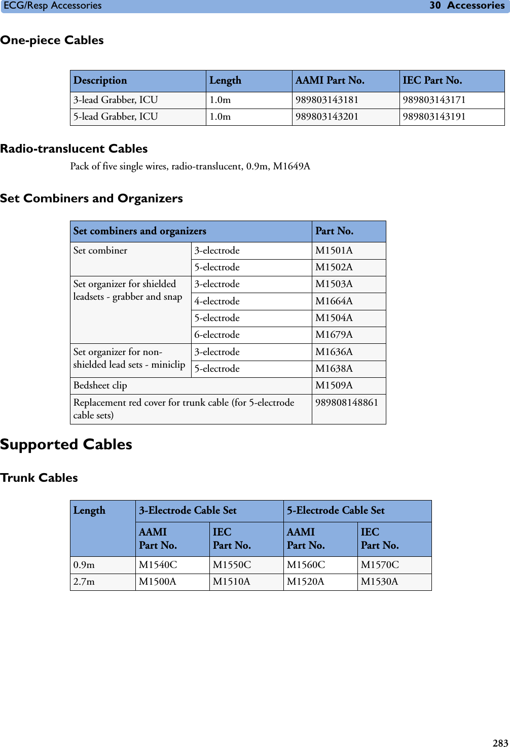
![Battery Power Indicators 28 Using Batteries273Battery Status Window♦To access the Battery Status window and its associated pop-up keys, select the battery status information on the Screen, or select Main Setup -> Battery. Capacity, remaining tells you how much power is left in the battery.Capacity, fullCharge tells you how much power the battery can hold when fully charged. TimeToEmpty tells you approximately how long you can continue to use the monitor with this battery. Note that this time fluctuates depending on the system load (the display brightness and how many measurements and recordings you carry out), the age of the battery, and the remaining capacity of the battery.TimeToEmpty tells you approximately how long you can continue to use the monitor with this battery. Note that this time fluctuates depending on the system load (the display brightness and how many measurements and recordings you carry out), the age of the battery, and the remaining capacity of the battery.TimeToFull is shown in place of TimeToEmpty if the monitor is connected to mains power, and tells you how much time is left until the battery is charged to 90%. If >10 hrs is shown here, the battery may not charge completely when the monitor is in use. You can use the M8043A Smart Battery Charger to charge the batteries externally.Recording Battery StatusTo print the information in the Battery Status window on a connected recorder,1Select the battery status information on the Screen to open the Battery Status window 2Select the Record Status pop-up key. Printing Battery ReportsTo print the information in the Battery Status window on a connected printer,battery not charging as the temperature is above or below the specified range(red) battery malfunction battery requires maintenance (red) battery has no power leftcharging stopped to protect the battery (red) battery temperature too highBattery StatusTimeToEmpty:CapacityremainingfullCharge[mAh][mAh]5:20 hrs57006135](https://usermanual.wiki/Philips-Medical-Systems-North-America/SRRBV1.User-Manual-MP5-and-MP5T/User-Guide-1044633-Page-283.png)


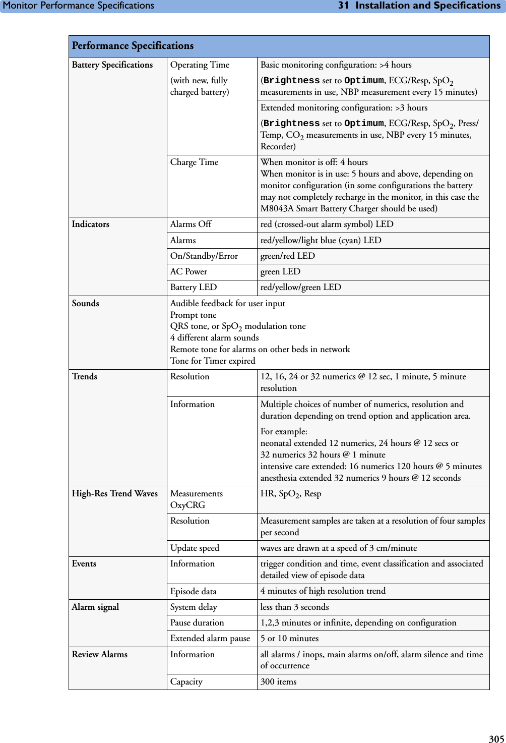
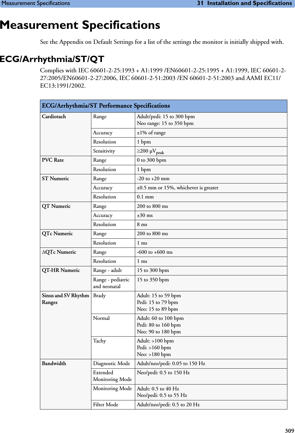
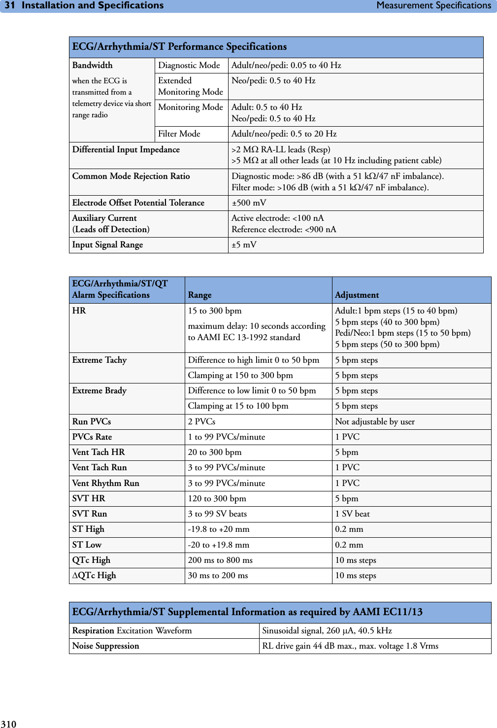
![Measurement Specifications 31 Installation and Specifications311RespirationTime to Alarm for TachycardiaVent Tachycardia1mVpp,206 bpmGain 0.5, Range 6.5 to 8.4 seconds, Average 7.2 secondsGain 1.0 Range 6.1 to 6.9 seconds, Average 6.5 secondsGain 2.0, Range 5.9 to 6.7 seconds, Average 6.3 secondsVent Tachycardia2mVpp,195 bpmGain 0.5, Range 5.4 to 6.2 seconds, Average 5.8 secondsGain 1.0, Range 5.7 to 6.5 seconds, Average 6.1 secondsGain 2.0, Range 5.3 to 6.1 seconds, Average 5.7 secondsTall T-Wave Rejection Capability Exceeds ANSI/AAMI EC 13 Sect. 3.1.2.1(c) minimum recommended 1.2 mV T-Wave amplitudeHeart Rate Averaging Method Three different methods are used:Normally, heart rate is computed by averaging the 12 most recent RR intervals.For runs of PVCs, up to 8 RR intervals are averaged to compute the HR.If each of 3 consecutive RR intervals is greater than 1200 ms (that is, rate less than 50 bpm), then the 4 most recent RR intervals are averaged to compute the HR.Response Time of Heart Rate Meter to Change in Heart RateHR change from 80 to 120 bpm:Range: [6.4 to 7.2 seconds] Average: 6.8 secondsHR change from 80 to 40 bpm:Range: [5.6 to 6.4 sec] Average: 6.0 secondsHeart Rate Meter Accuracy and Response to Irregular RhythmVentricular bigeminy: 80 bpmSlow alternating ventricular bigeminy: 60 bpmRapid alternating ventricular bigeminy: 120 bpmBidirectional systoles: 90 bpmAccuracy of Input Signal Reproduction Methods A and D were used to establish overall system error and frequency response.Pacemaker Pulse Rejection Performance Rejection of pacemaker pulses with amplitudes from ±2 mV to ±700 mV and widths from 0.1 ms to 2.0 ms (Method A)ECG/Arrhythmia/ST Supplemental Information as required by AAMI EC11/13Respiration Performance SpecificationsRespiration Rate Range Adult/pedi: 0 to 120 rpmNeo: 0 to 170 rpmAccuracy at 0 to 120 rpm ±1 rpmat 120 to 170 rpm ±2 rpmResolution 1rpmBandwidth 0.3 to 2.5 Hz (–6 dB)Noise Less than 25 m(rms) referred to the input](https://usermanual.wiki/Philips-Medical-Systems-North-America/SRRBV1.User-Manual-MP5-and-MP5T/User-Guide-1044633-Page-321.png)


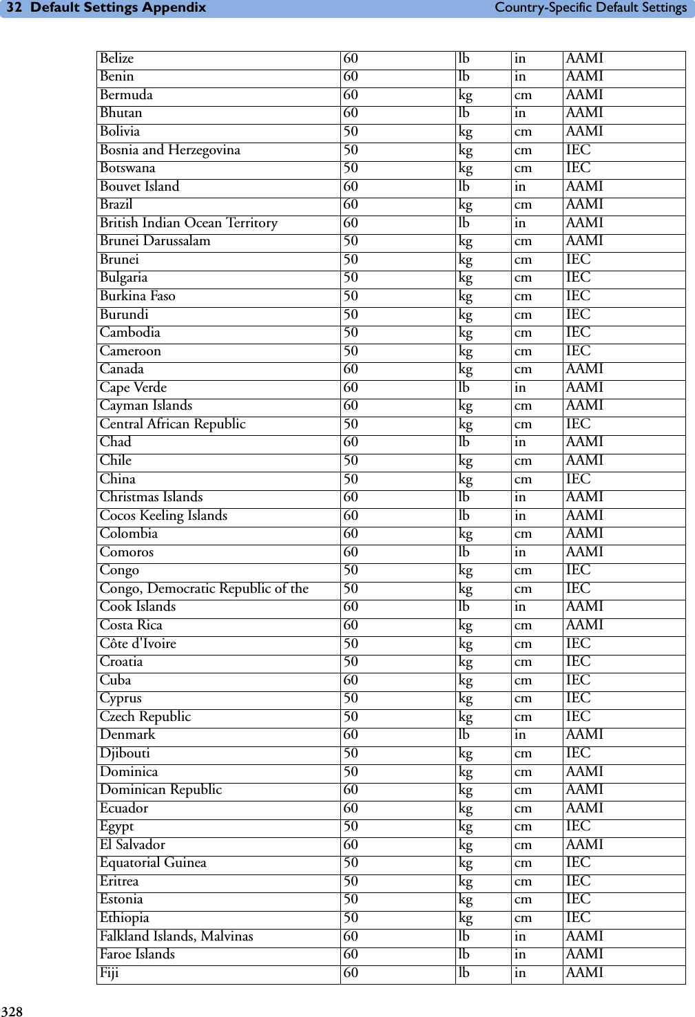
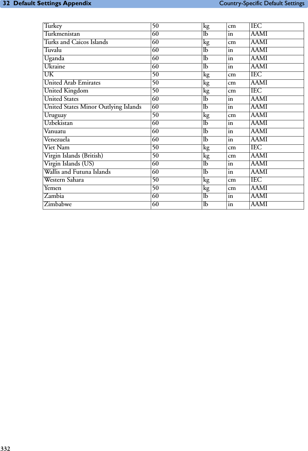
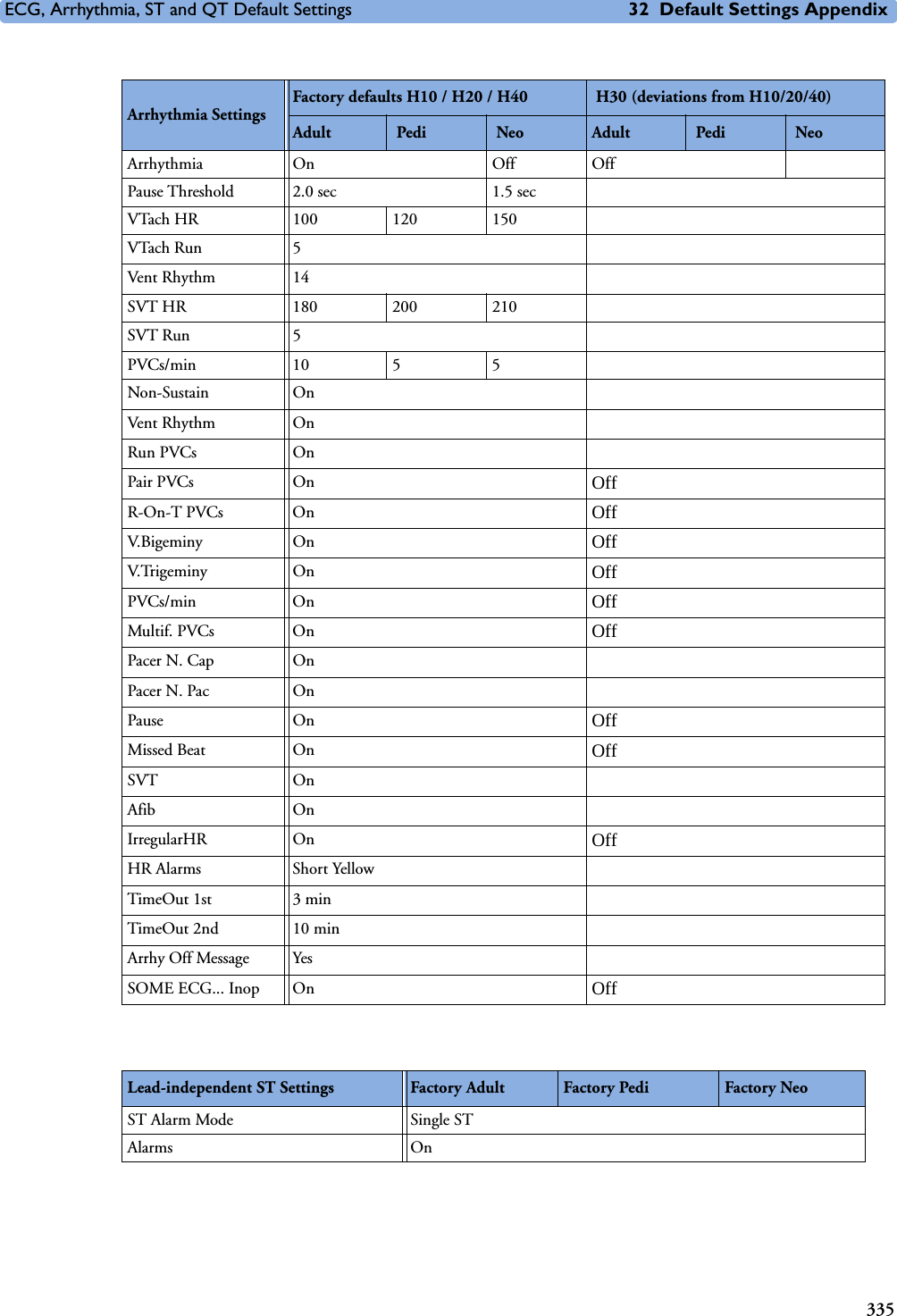
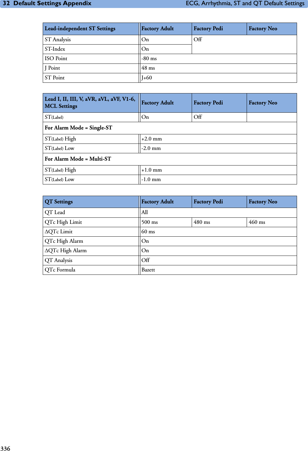
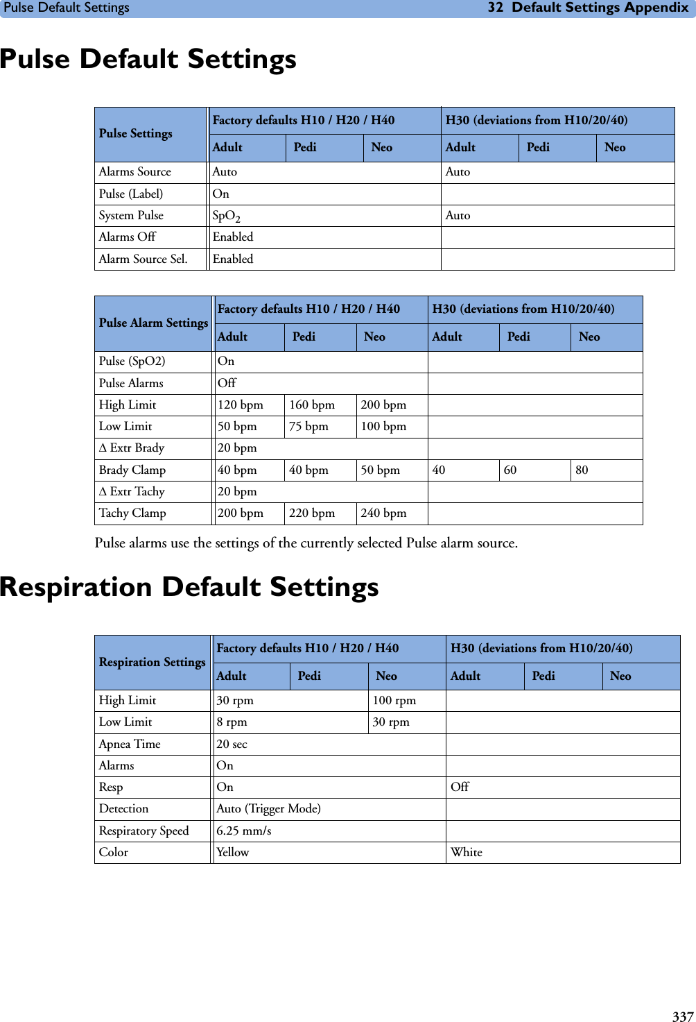
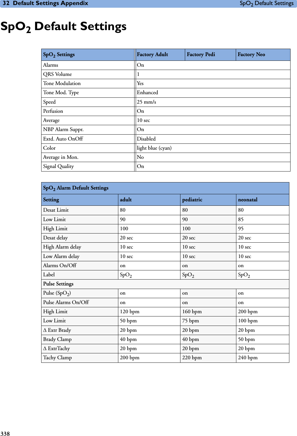
![3273232Default Settings AppendixThis appendix documents the most important default settings of your monitor as it is delivered from the factory. For a comprehensive list and explanation of default settings, see the Configuration Guide supplied with your monitor. The monitor’s default settings can be permanently changed in Configuration Mode. Note: If your monitor has been ordered preconfigured to your requirements, the settings at delivery will be different from those listed here. Country-Specific Default SettingsCertain default settings are specific to a particular country. These are listed here for all countries alphabetically.Country-Description Line Frequency UnitsWeightUnitsHeightECG Cable Color50/60 [Hz] kg, lb in, cm IEC, AAMIAfghanistan 50 kg cm AAMIÅland Islands 50 kg cm IECAlbania 50 kg cm IECAlgeria 50 kg cm IECAmerican Samoa 60 lb in AAMIAndorra 60 lb in AAMIAngola 50 kg cm IECAnguilla 60 lb in AAMIAntarctica 60 lb in AAMIAntigua and Barbuda 50 kg cm AAMIArgentina 50 kg cm AAMIArmenia 50 kg cm IECAruba 60 kg cm AAMIAustralia 50 kg cm AAMIAustria 50 kg cm IECAzerbaijan 50 kg cm IECBahamas, The 60 kg cm AAMIBahrain 50 kg cm AAMIBangladesh 60 lb in AAMIBarbados 50 kg cm AAMIBelarus 50 kg cm IECBelgium 50 kg cm IEC](https://usermanual.wiki/Philips-Medical-Systems-North-America/SRRBV1.User-Manual-MP5-and-MP5T/User-Guide-1044633-Page-337.png)