Philips Medical Systems North America WLANBV3 WLAN Module IEEE 802.11 a/b/g/n User Manual ait fm manual MP2 en 2015 04 20
Philips Medical Systems North America Co. WLAN Module IEEE 802.11 a/b/g/n ait fm manual MP2 en 2015 04 20
Contents
- 1. User manual
- 2. user_manual mp2 english
- 3. user manual 865221 english
user_manual mp2 english

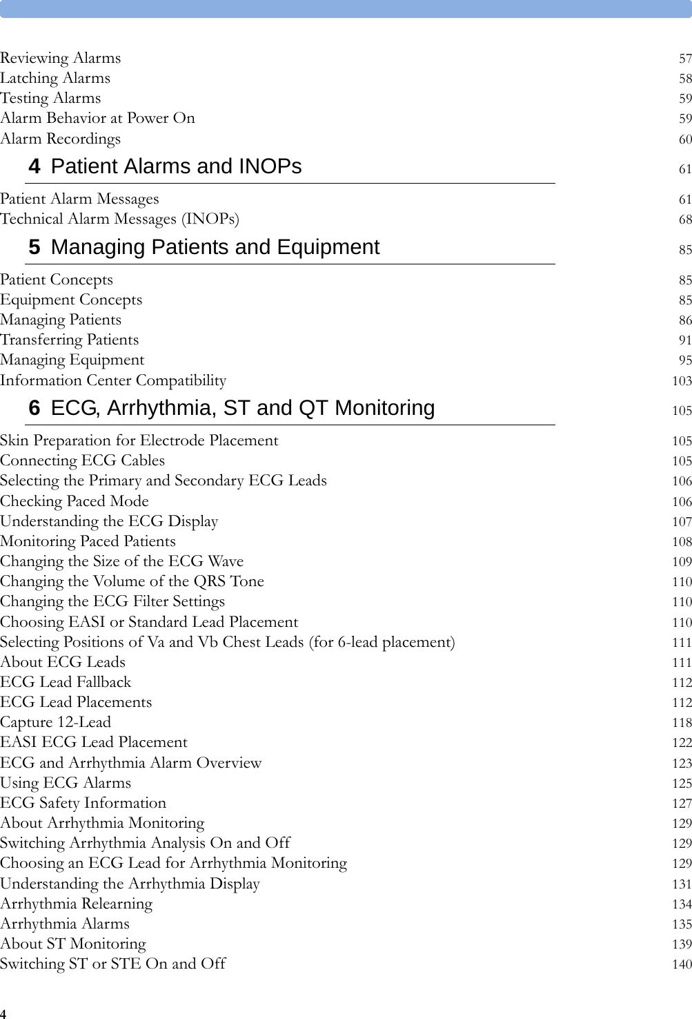
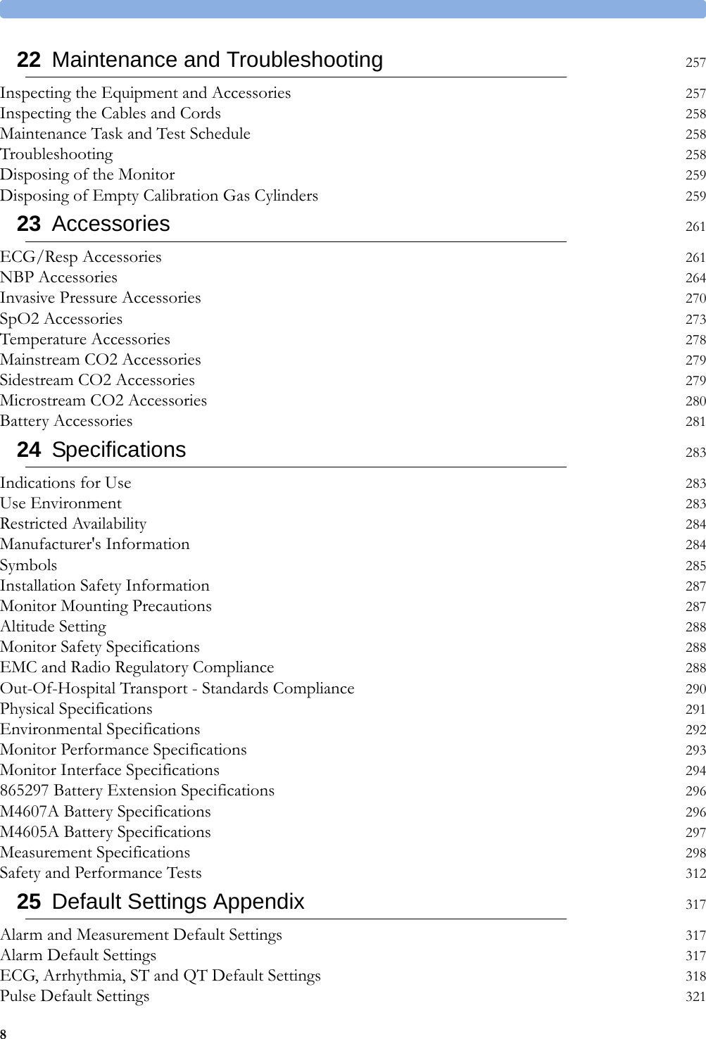


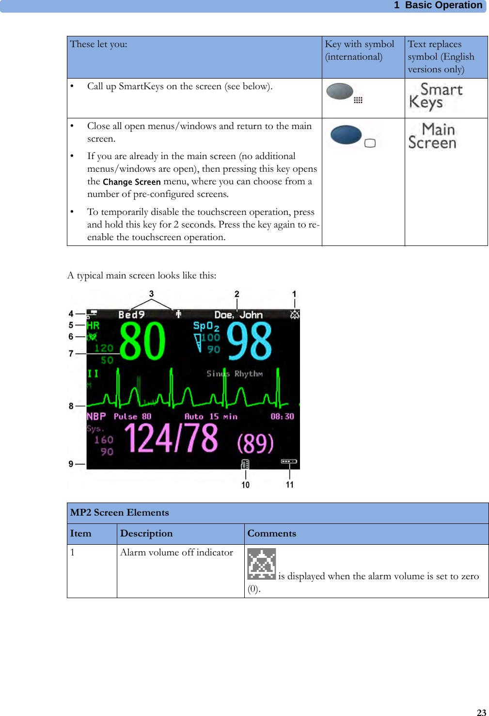
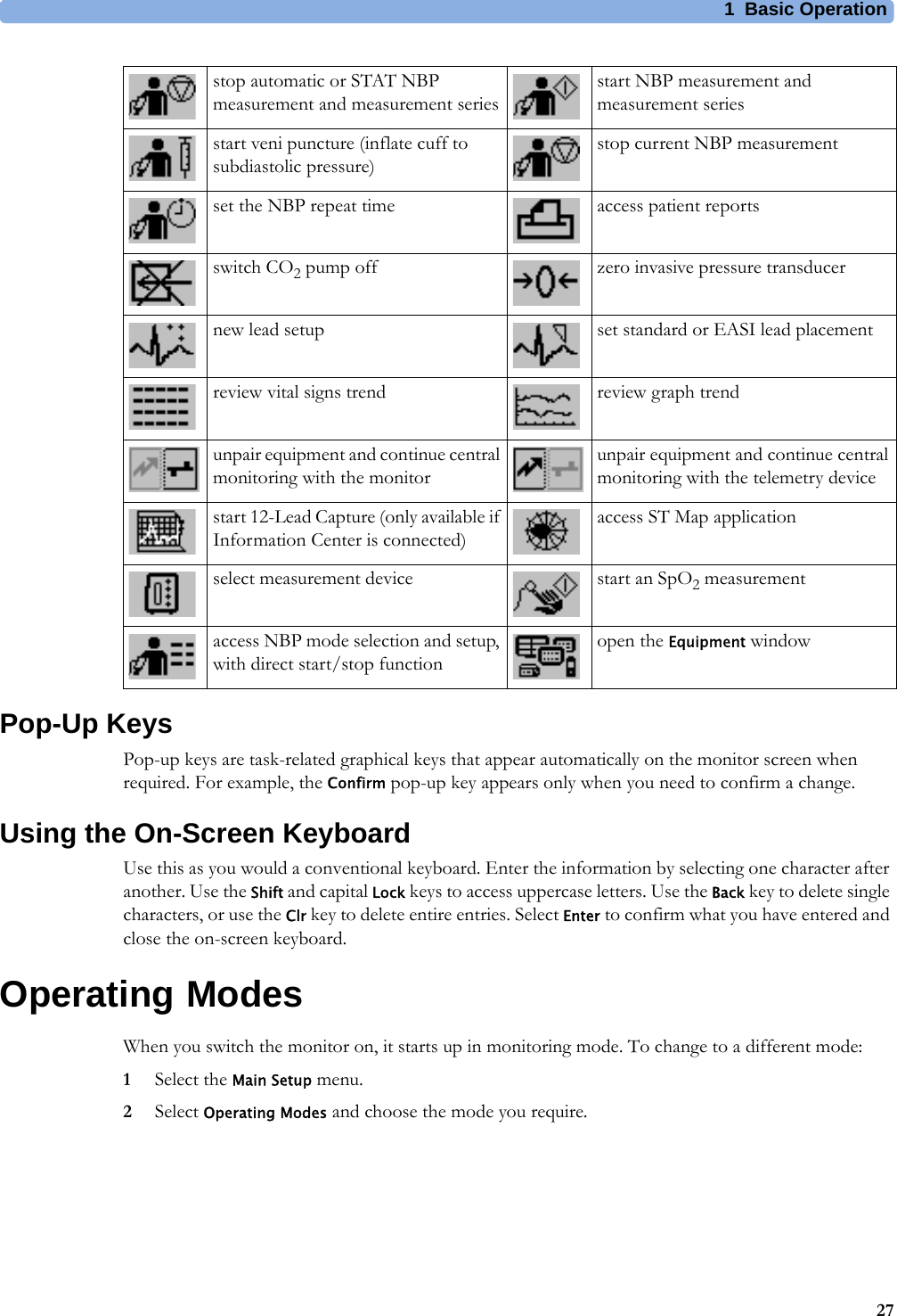
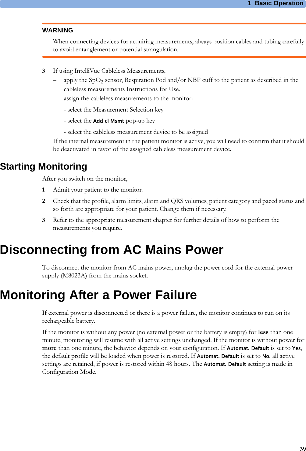
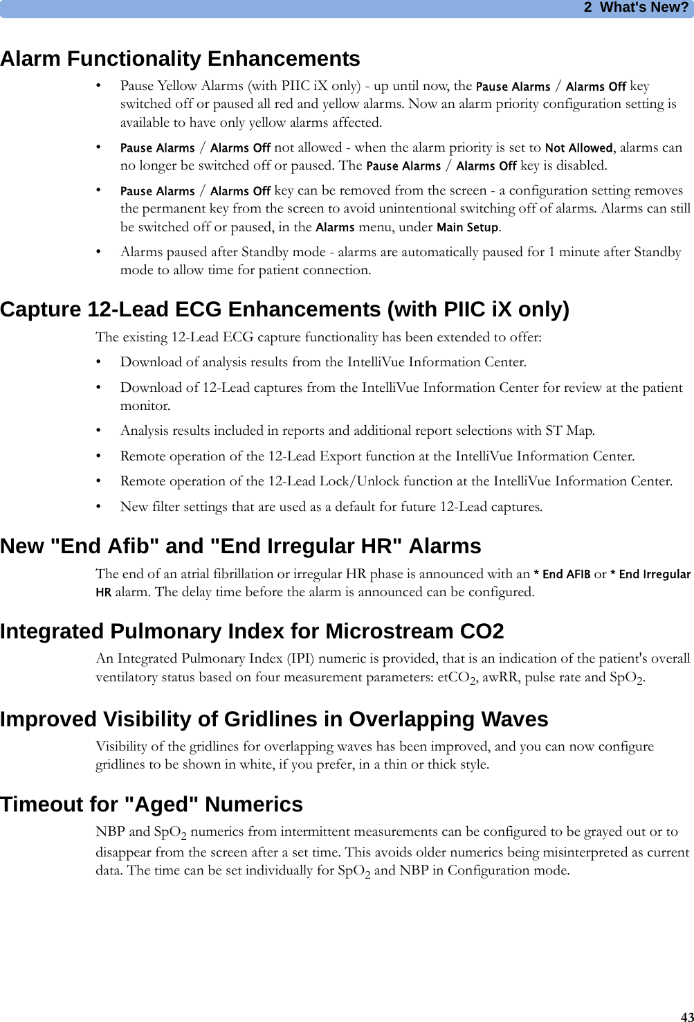

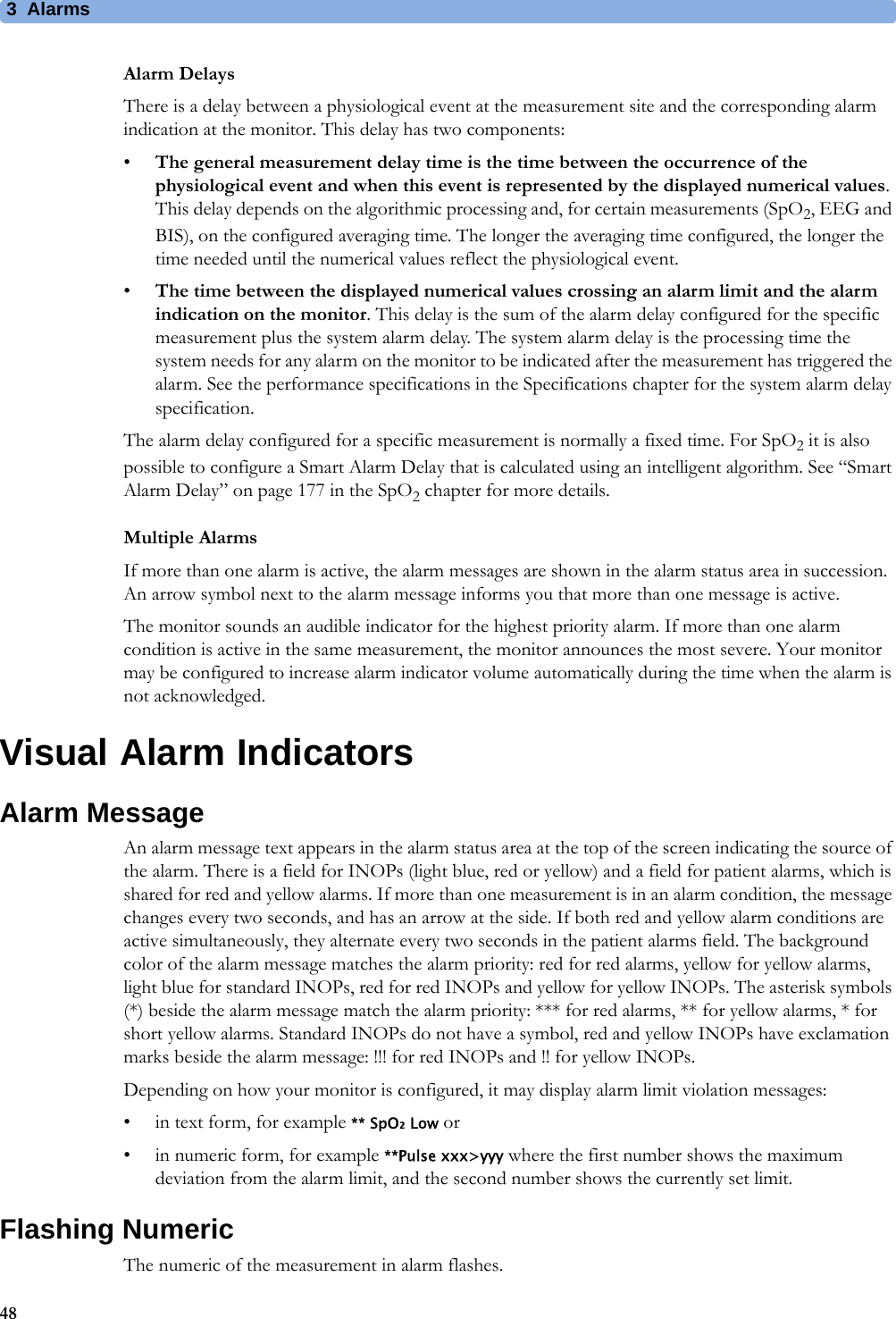
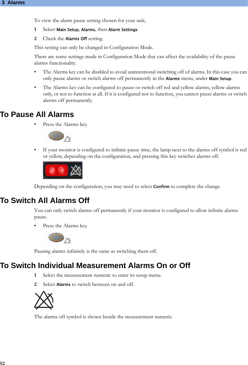
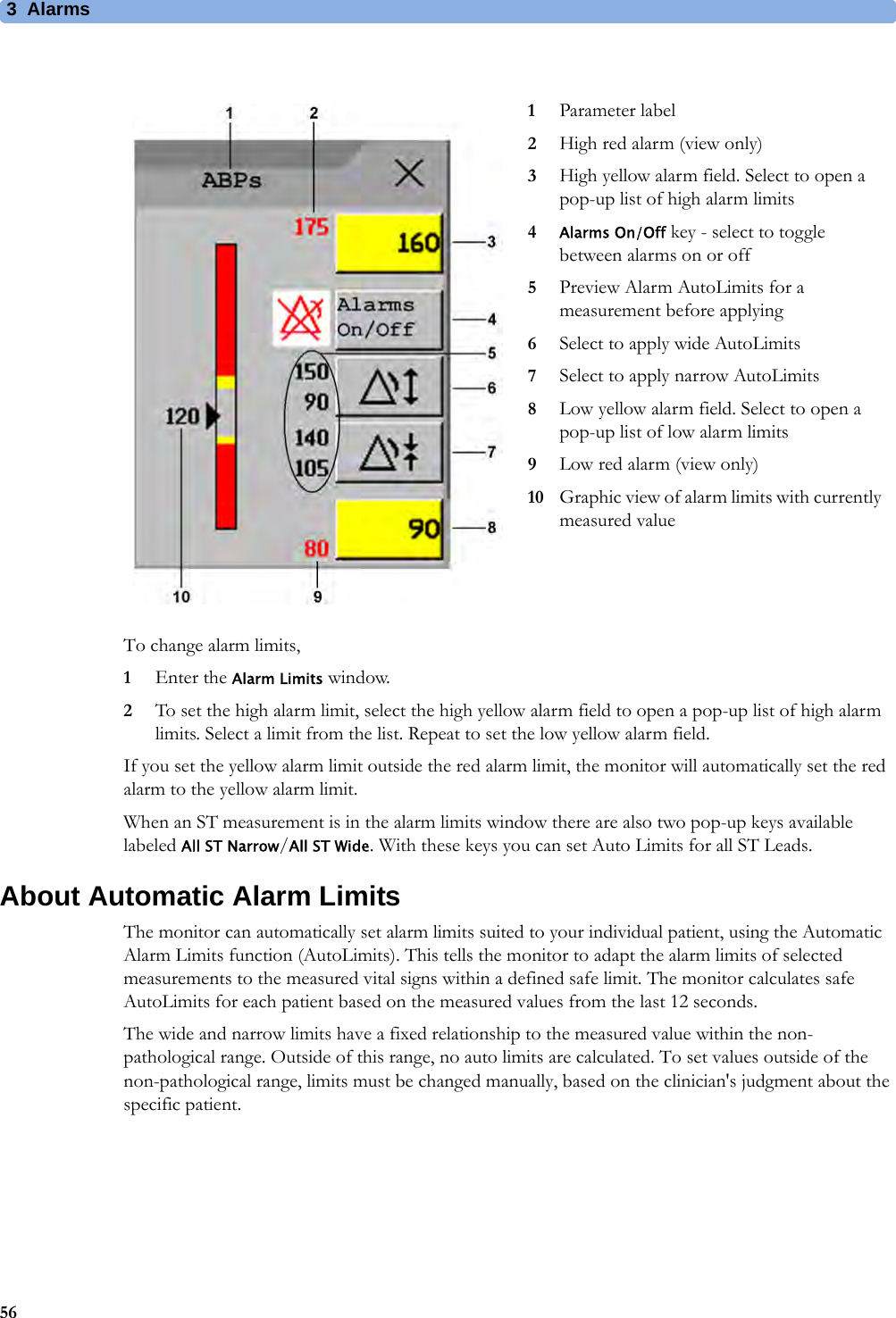
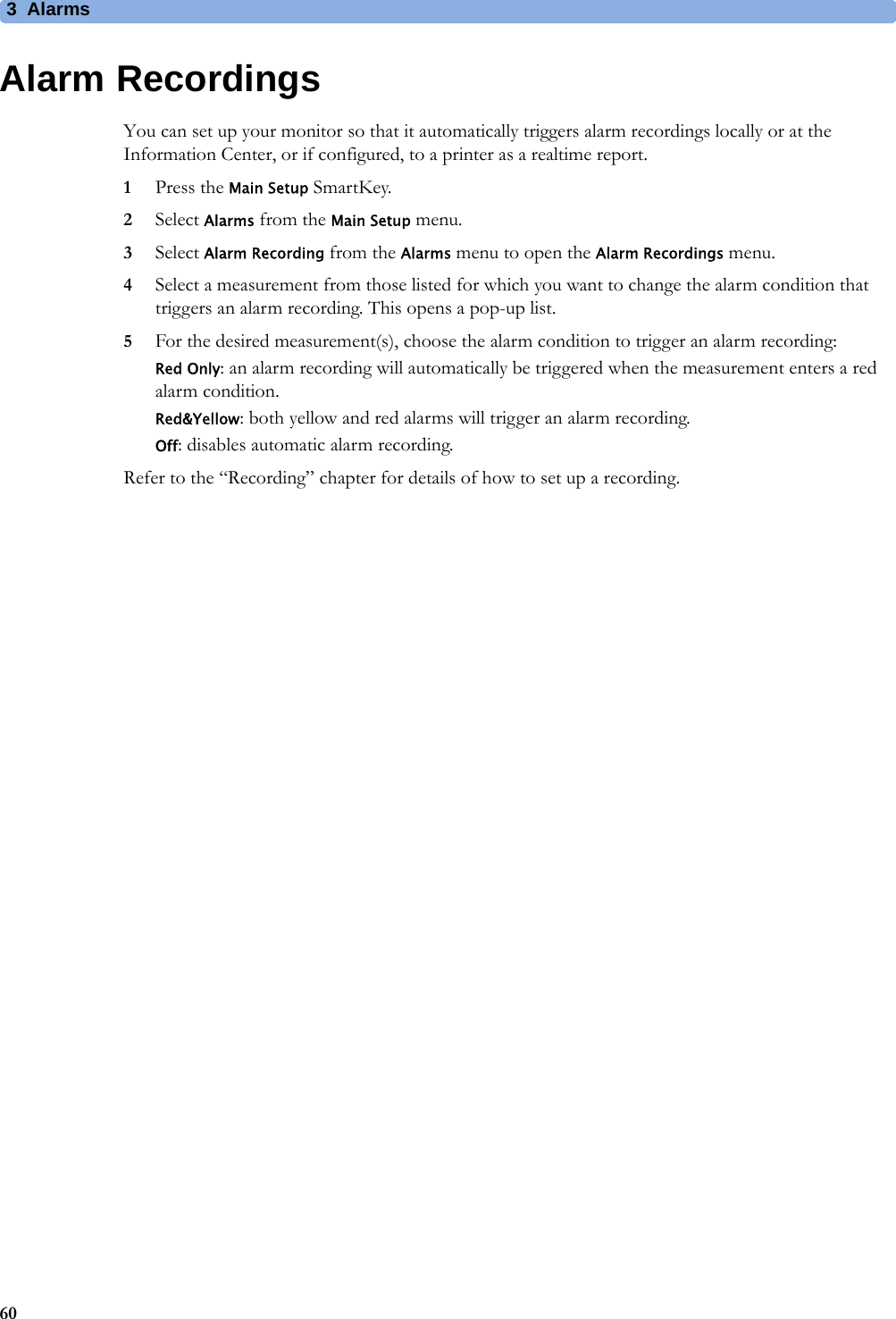
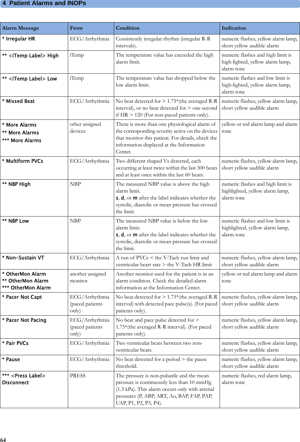
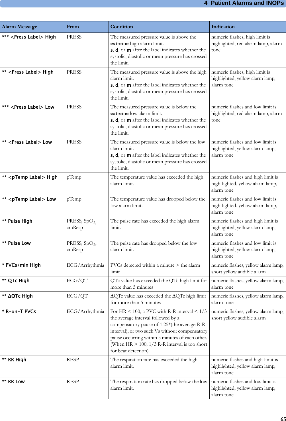
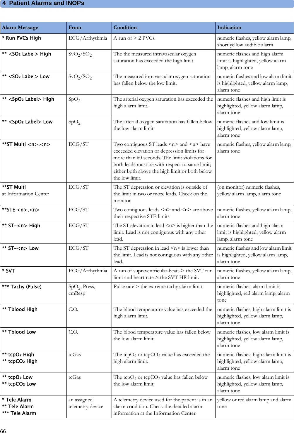
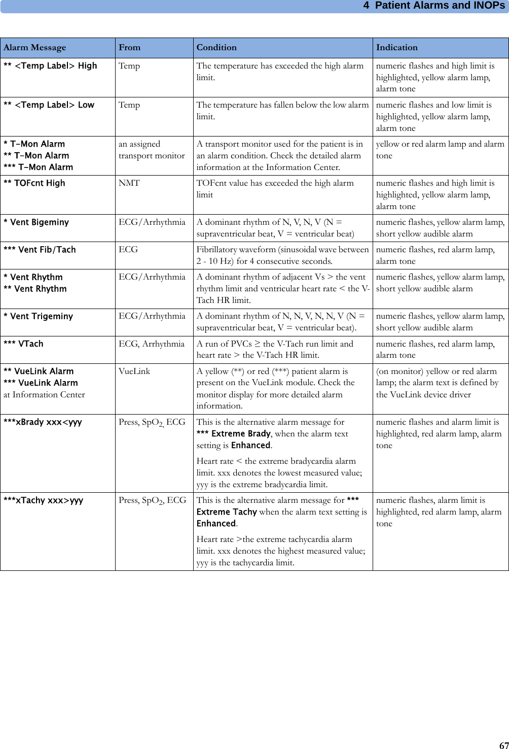
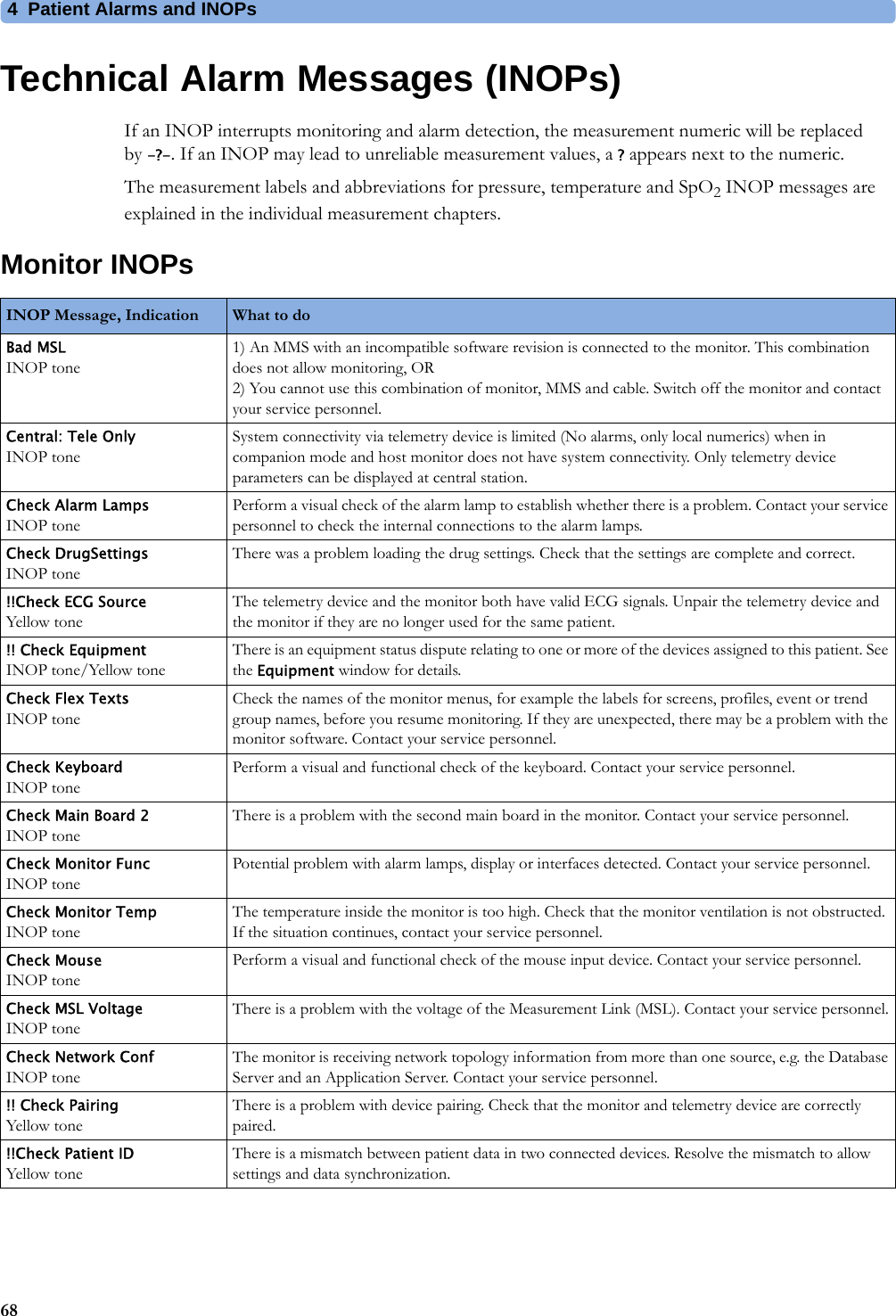
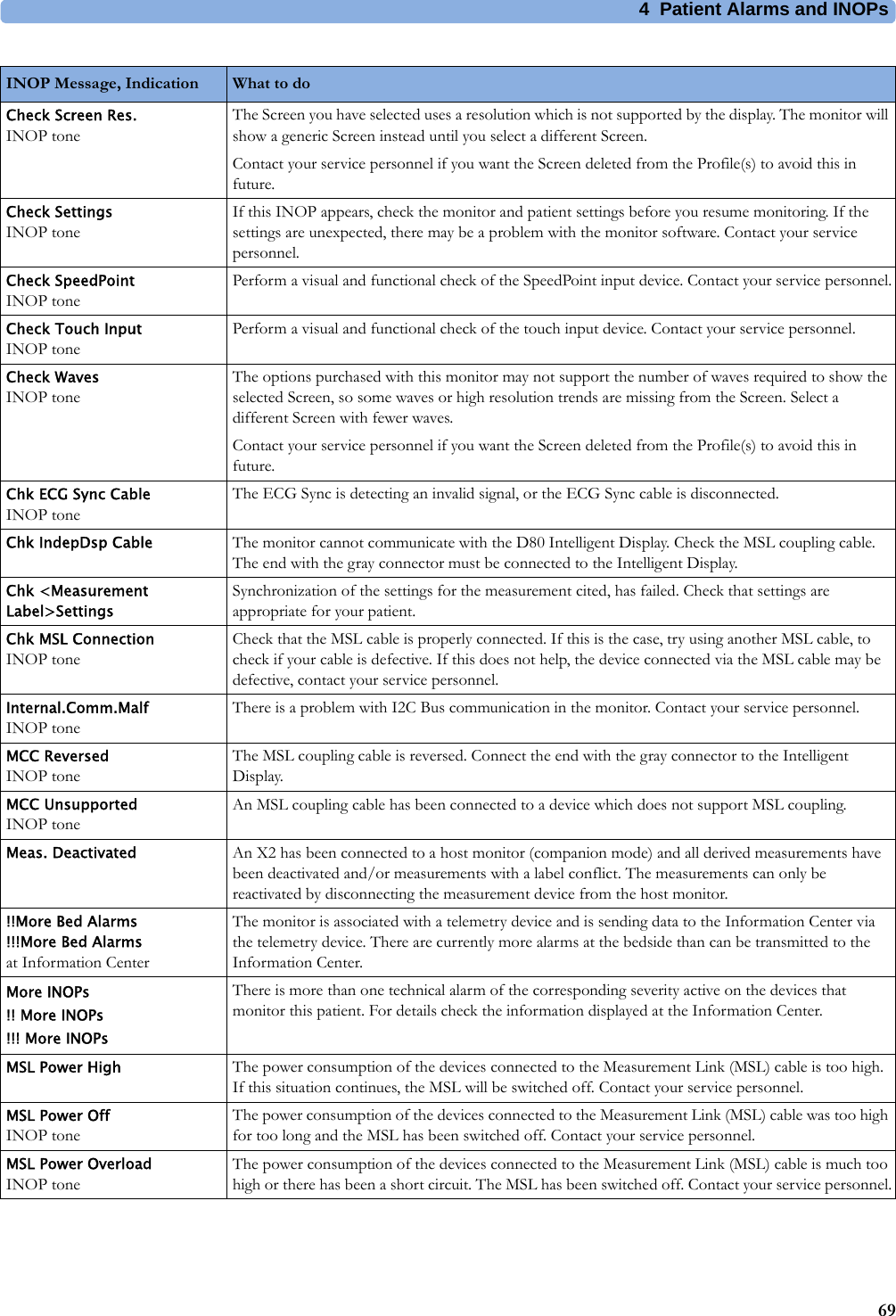
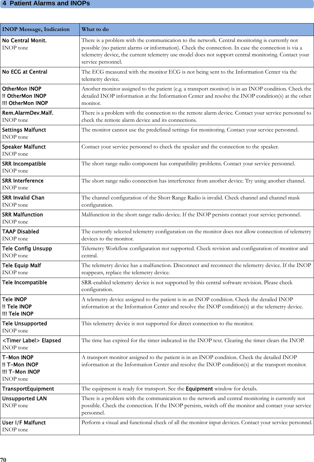
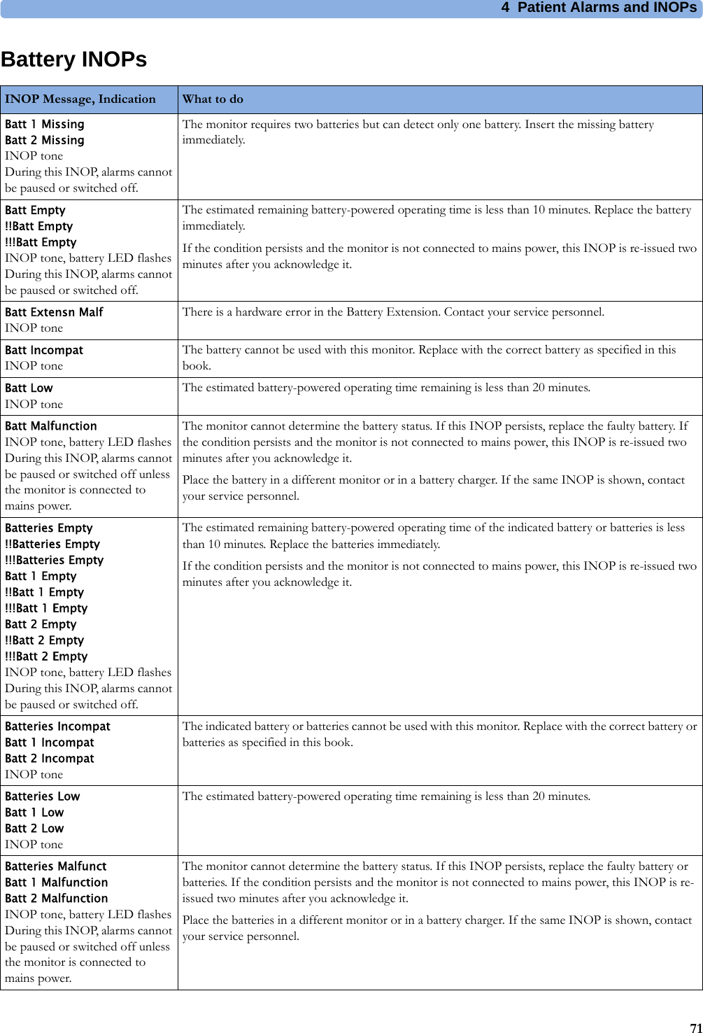
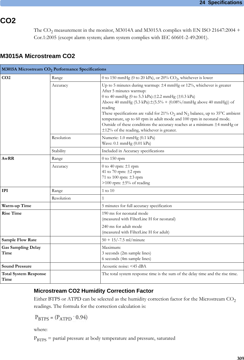
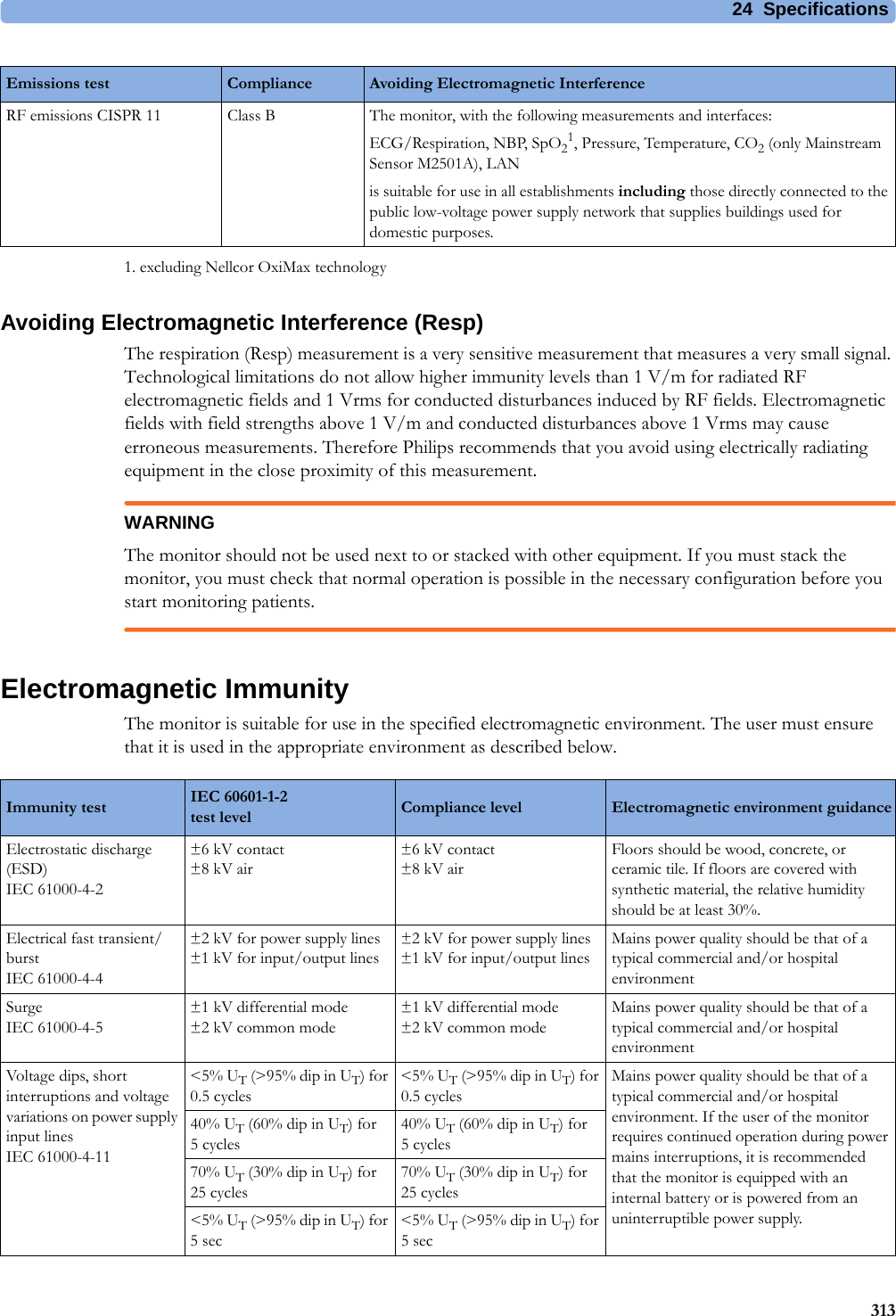
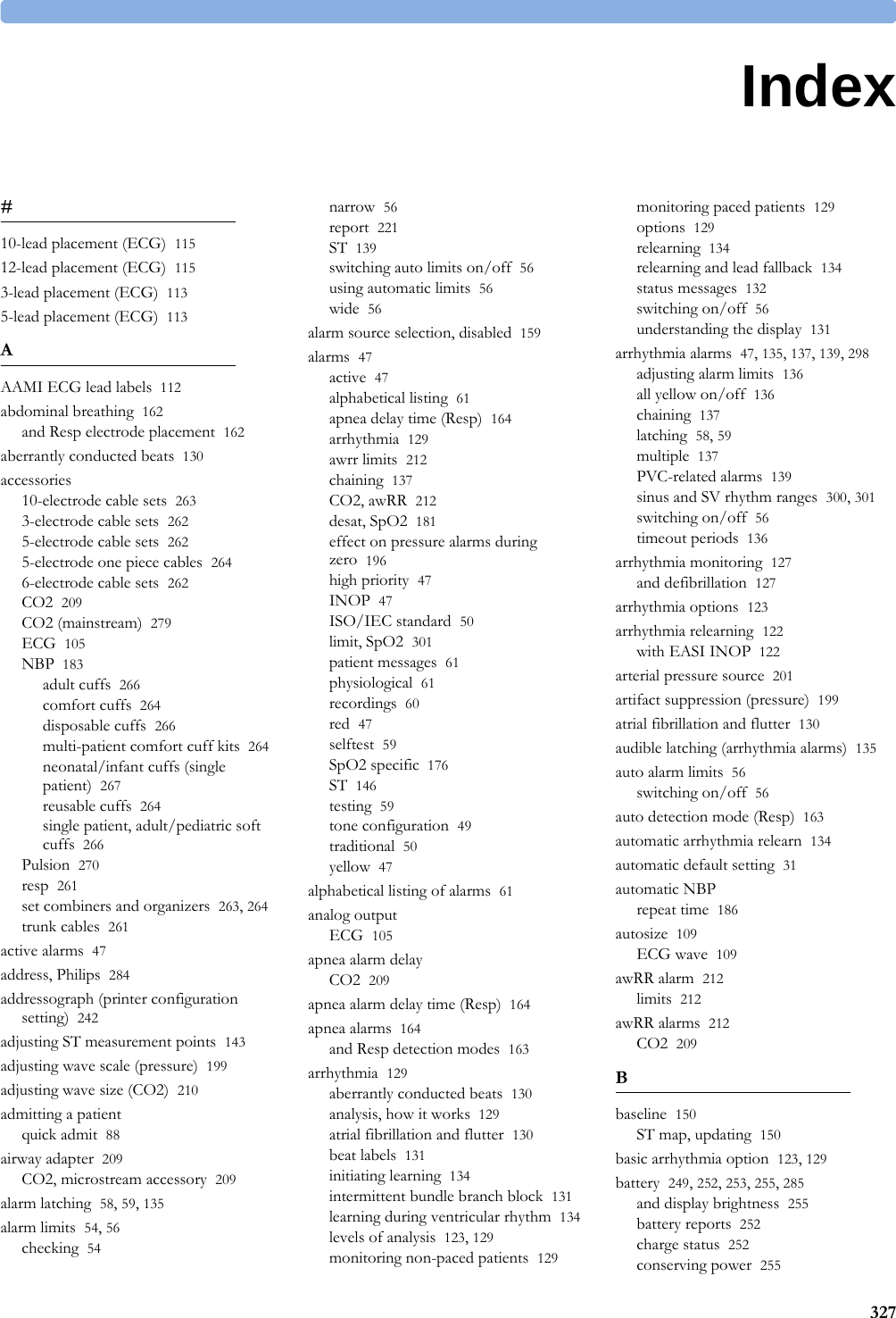
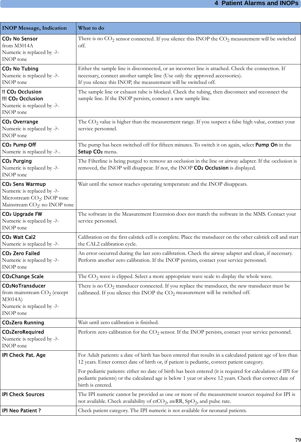
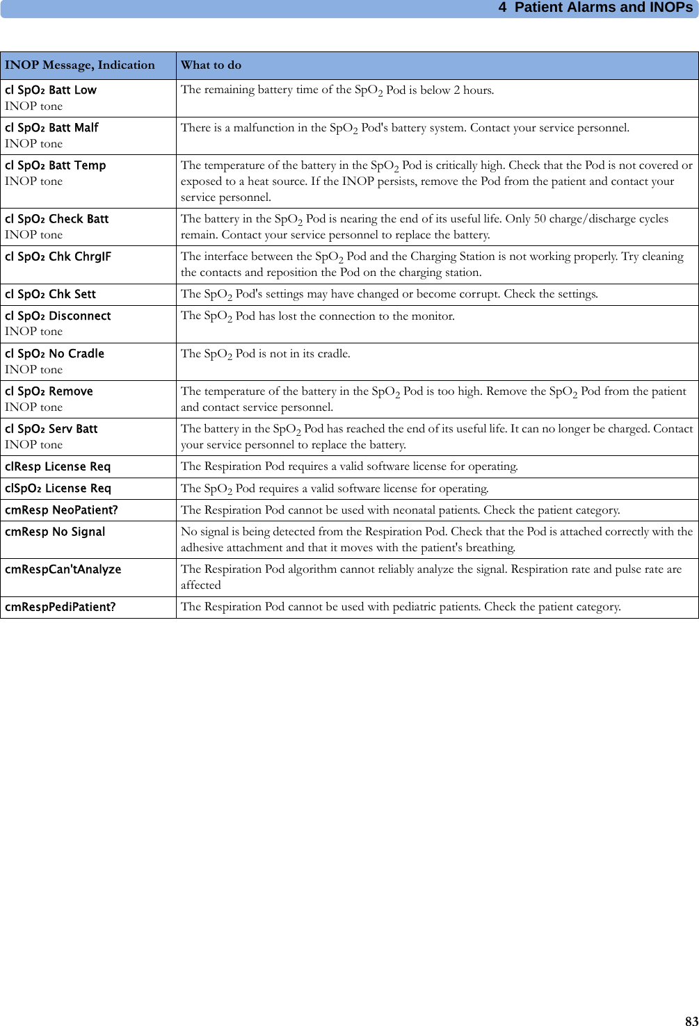
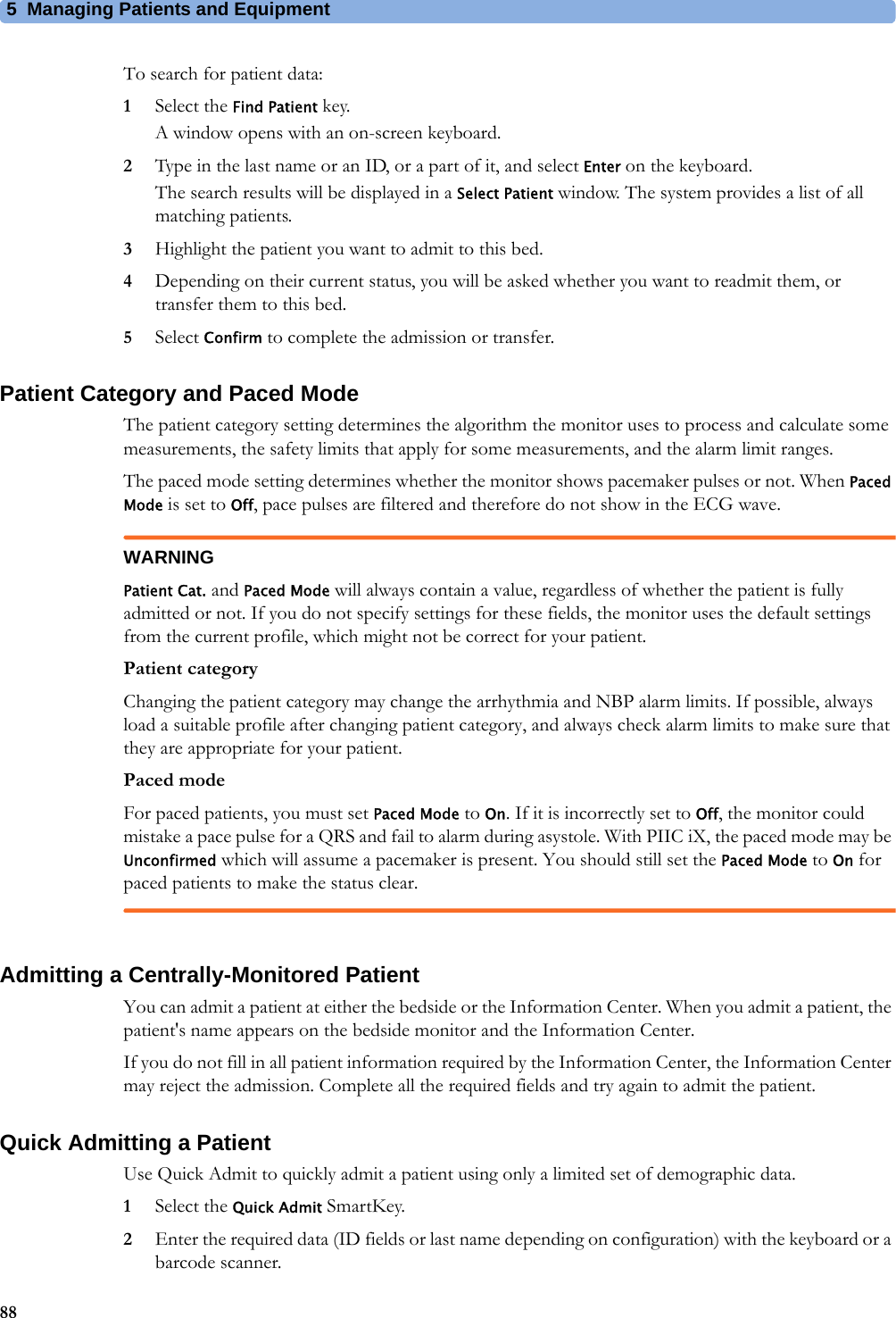
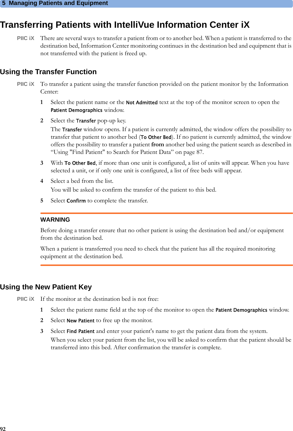
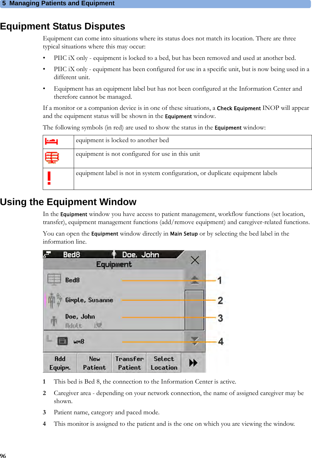
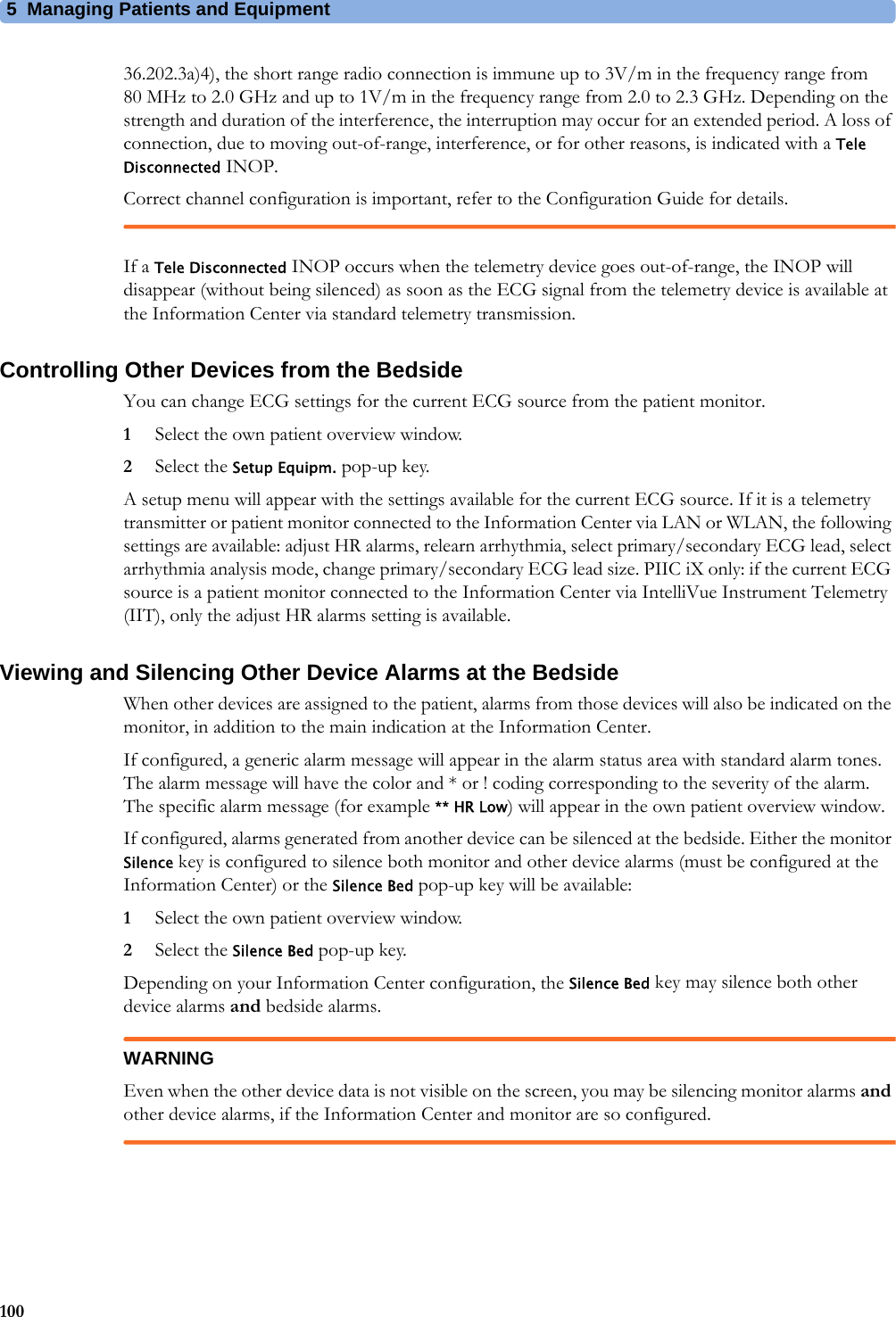
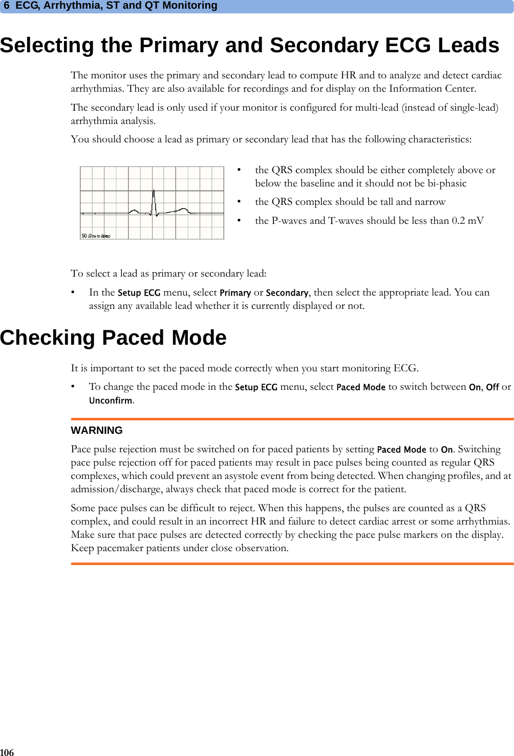
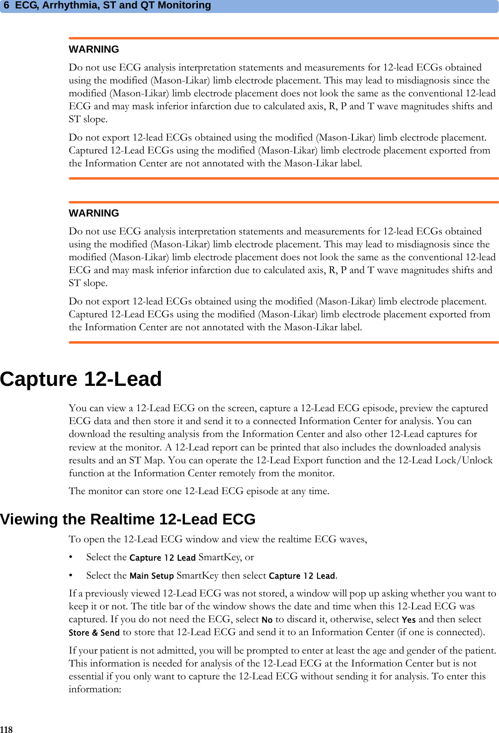
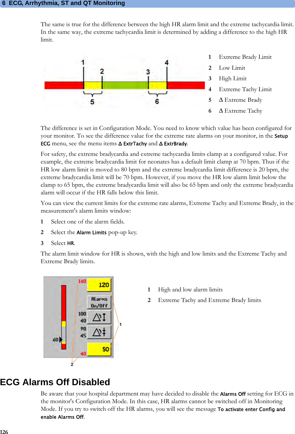
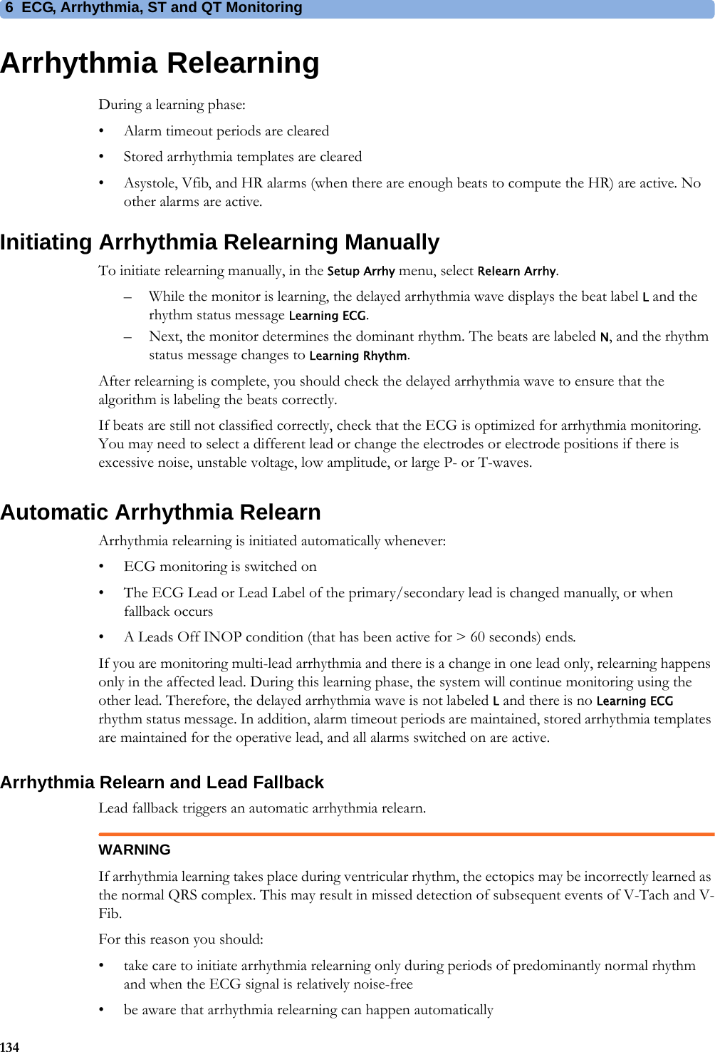
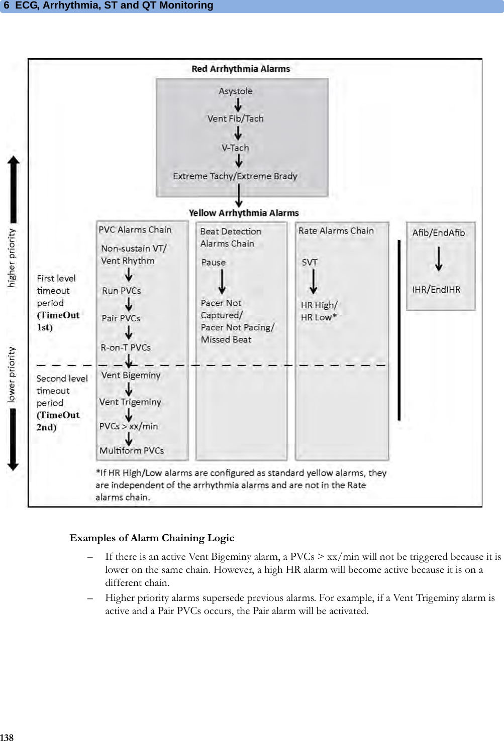
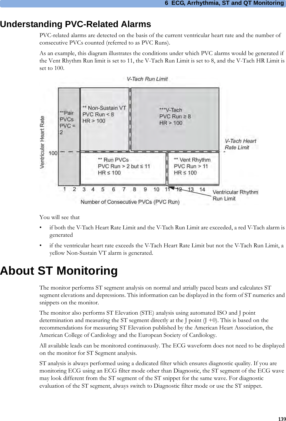
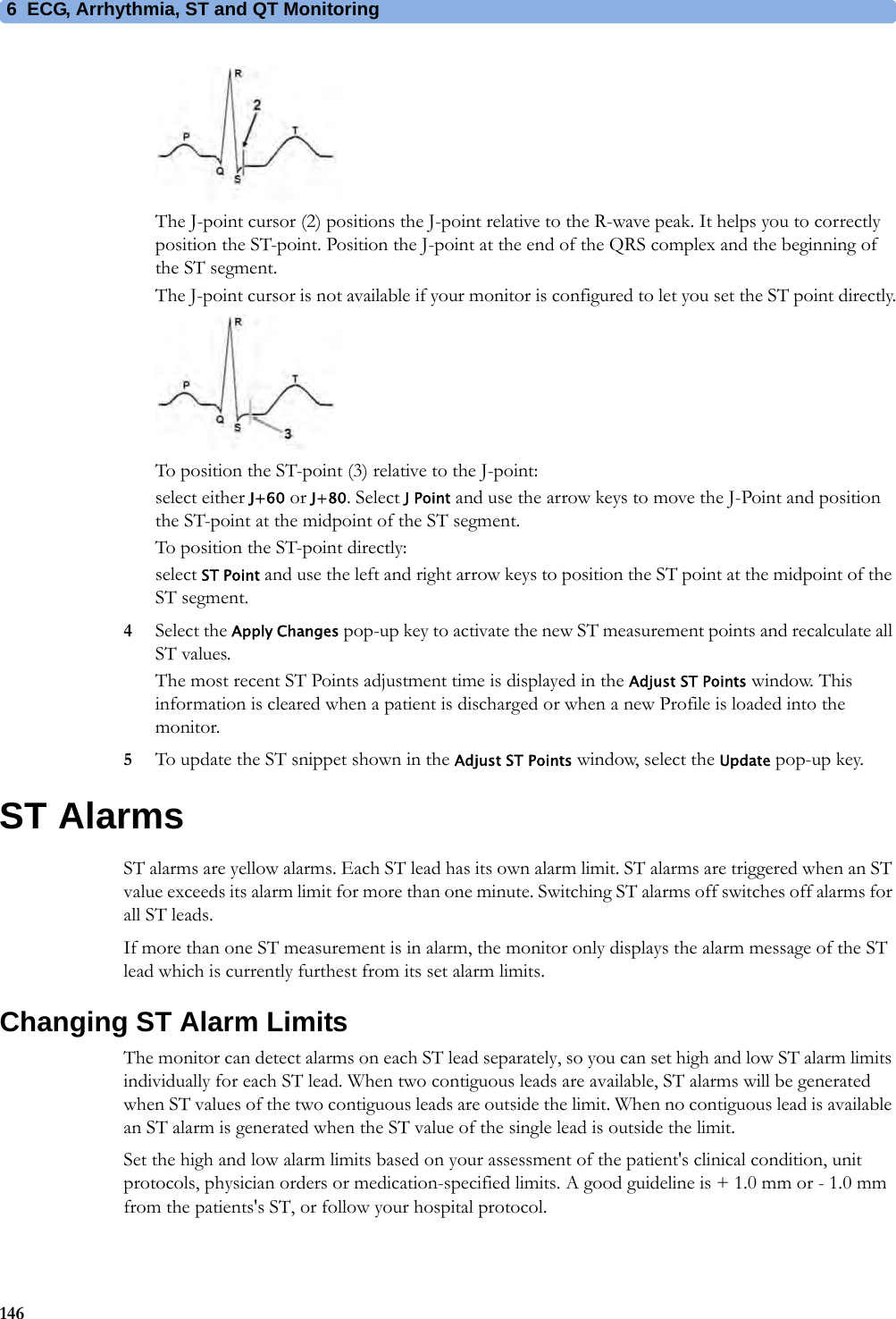
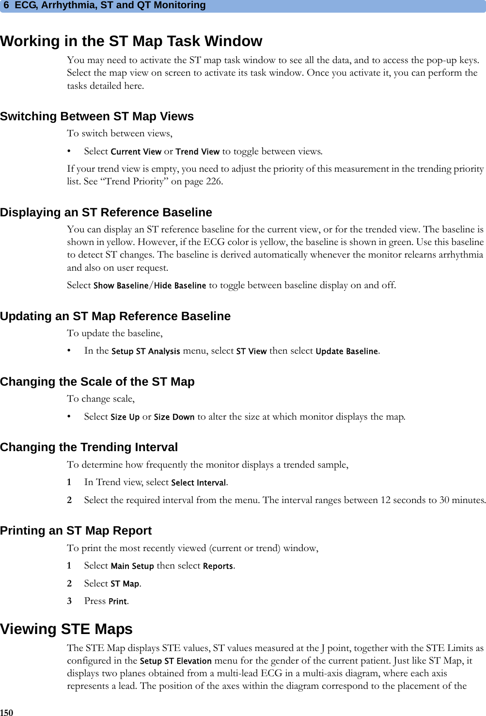
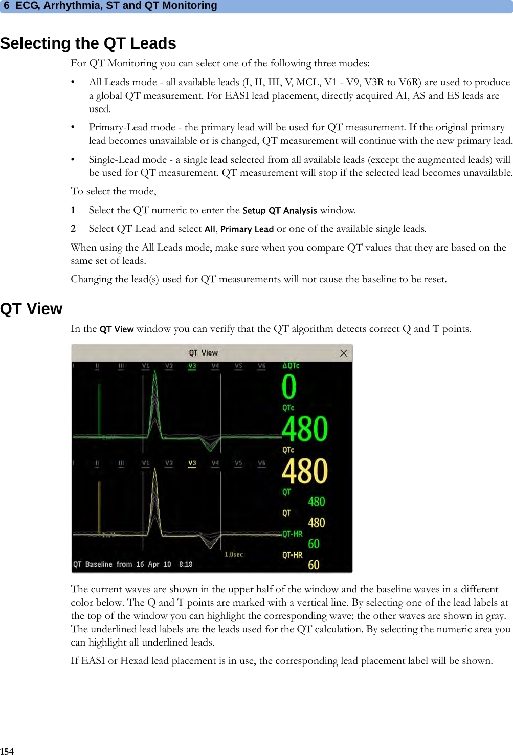
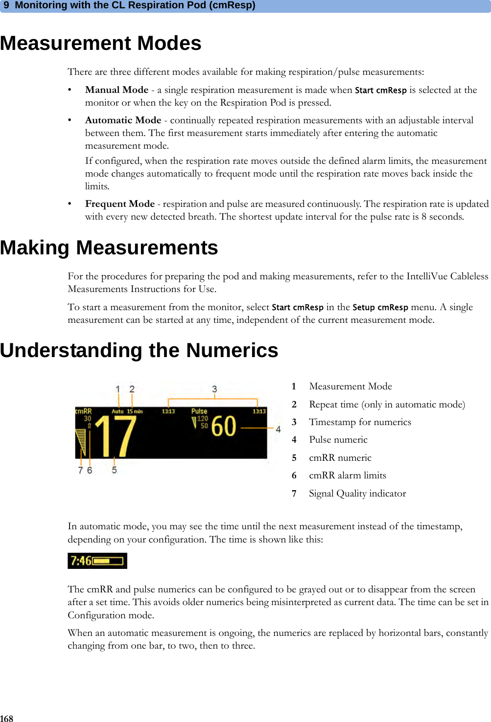
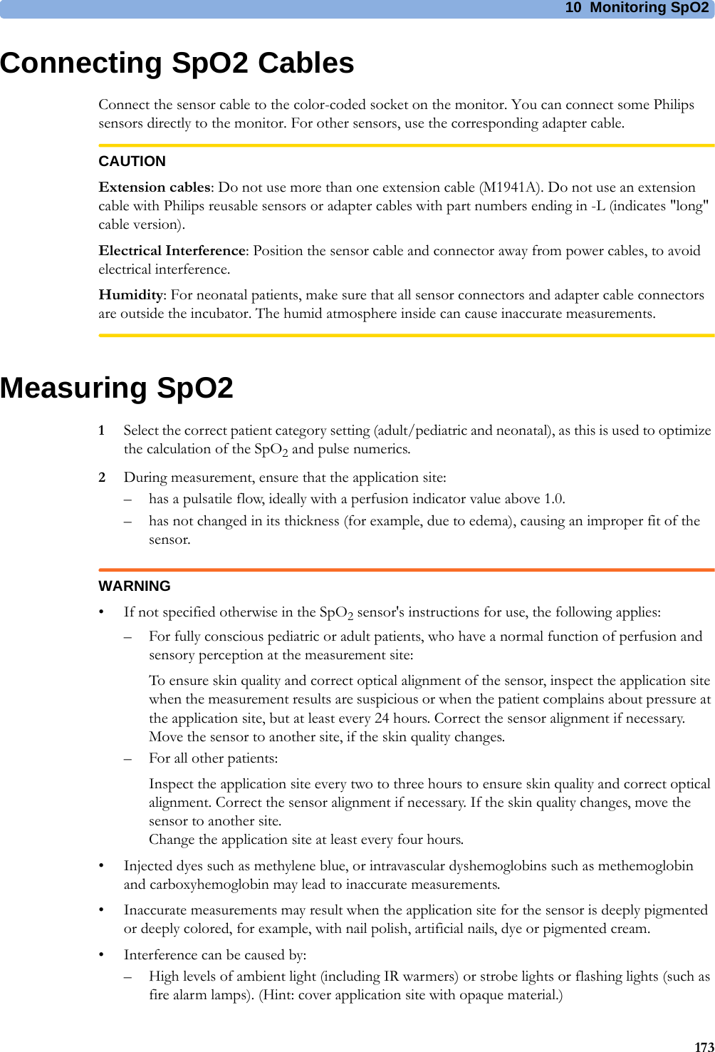
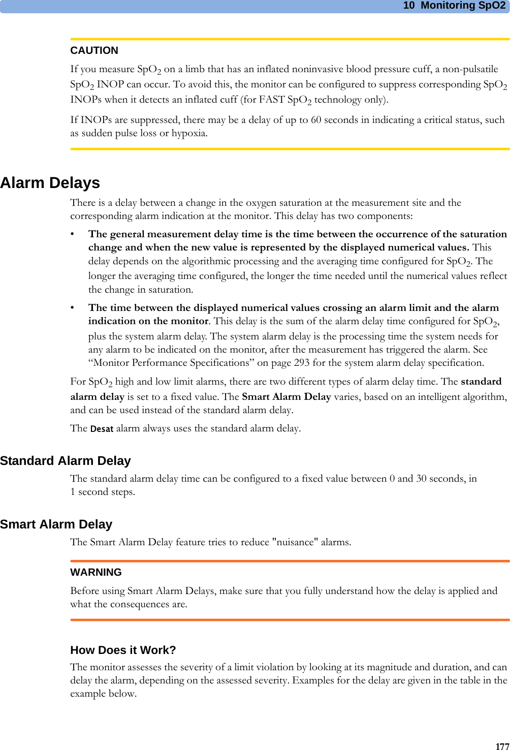
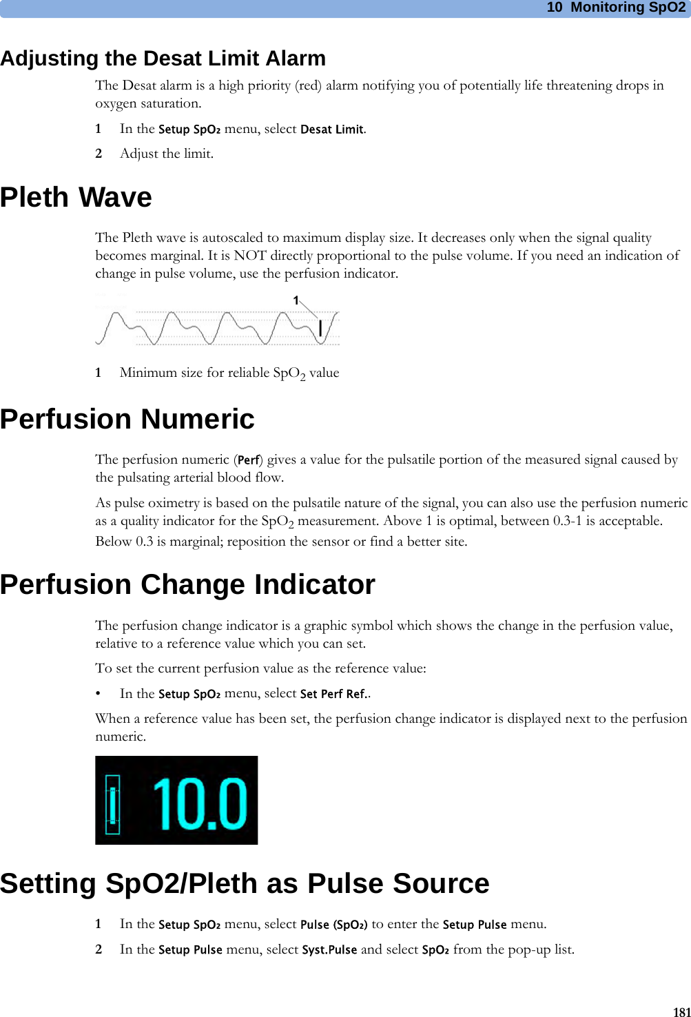
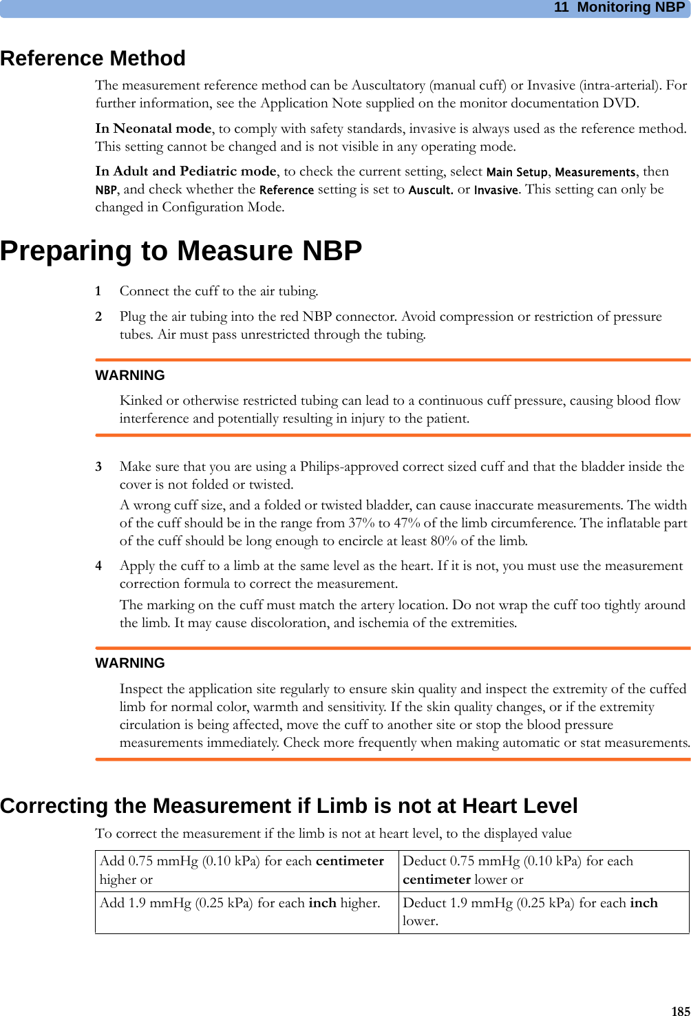
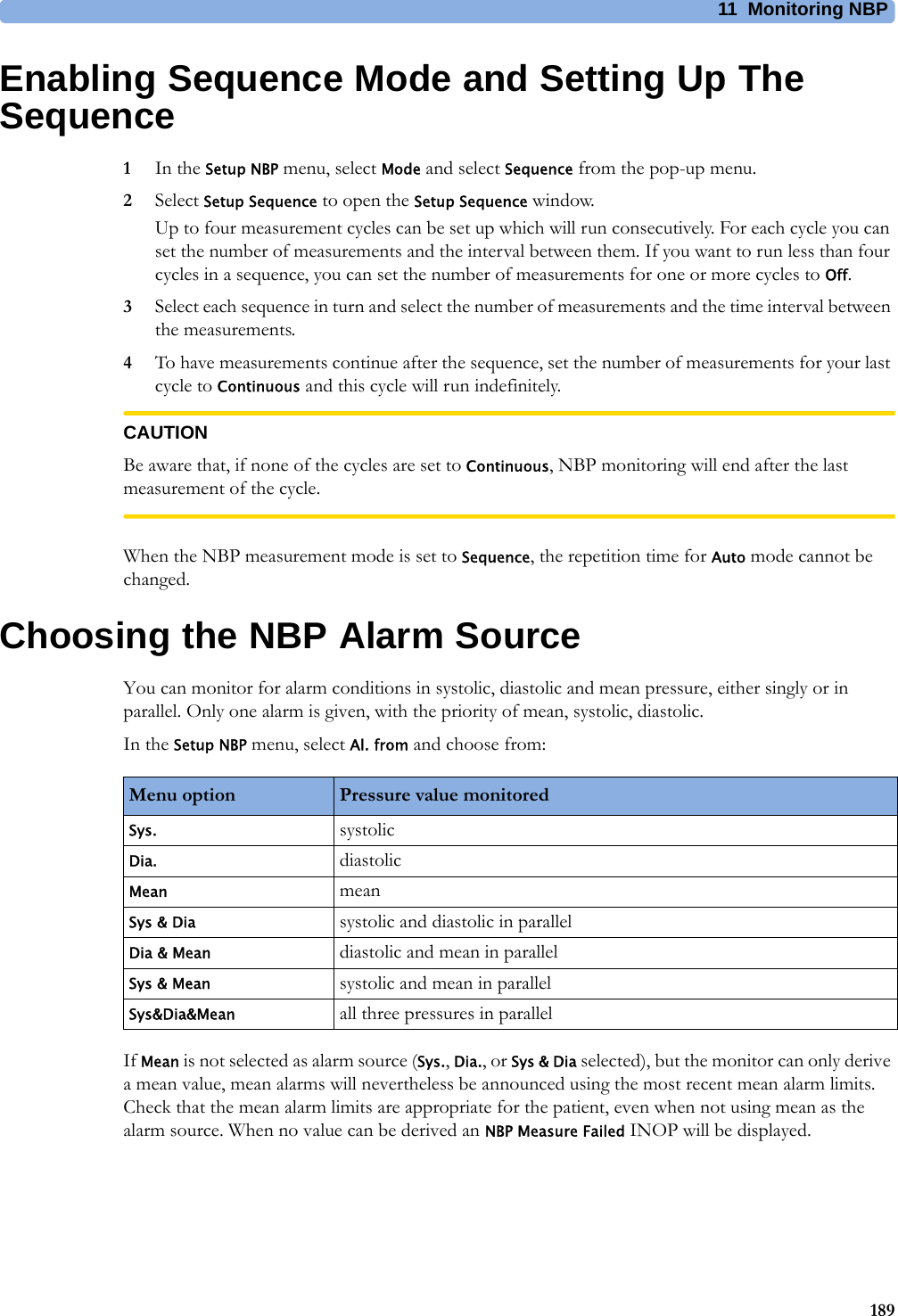
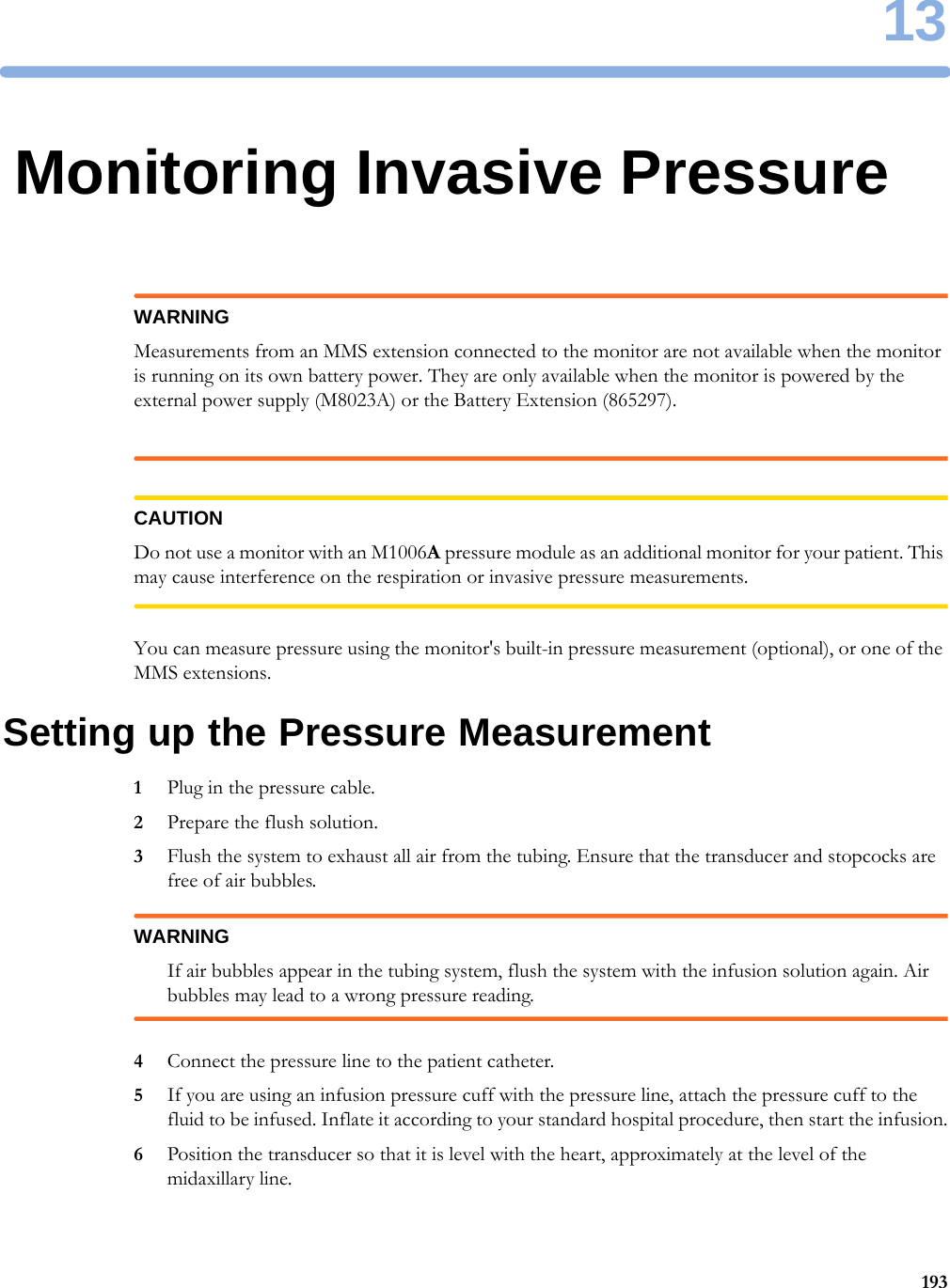
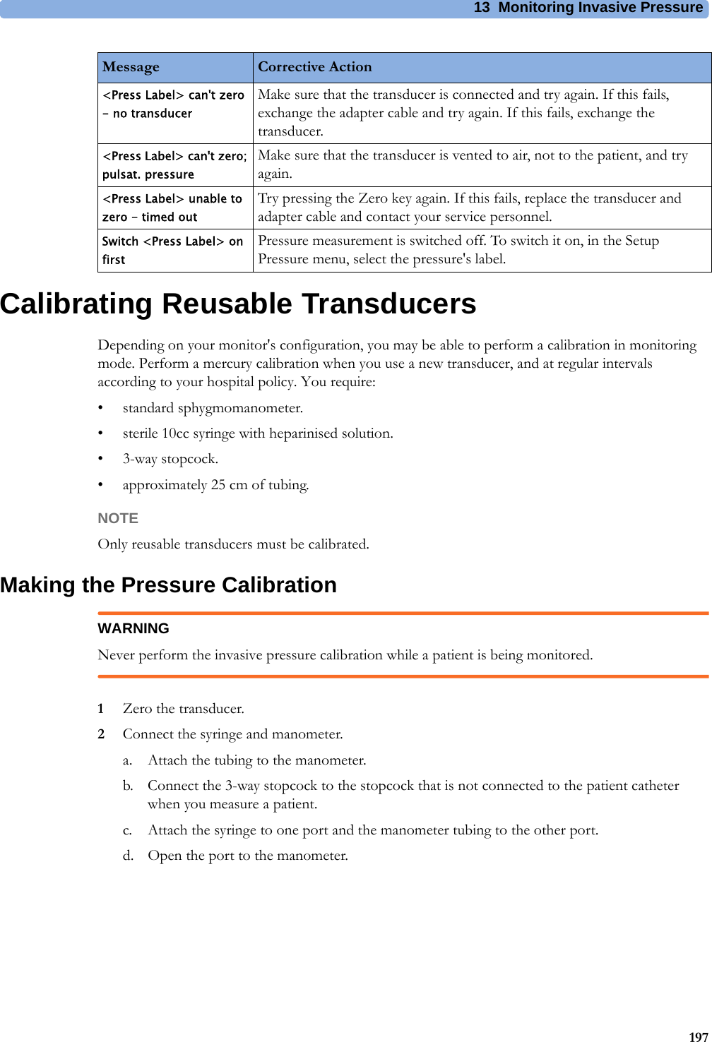
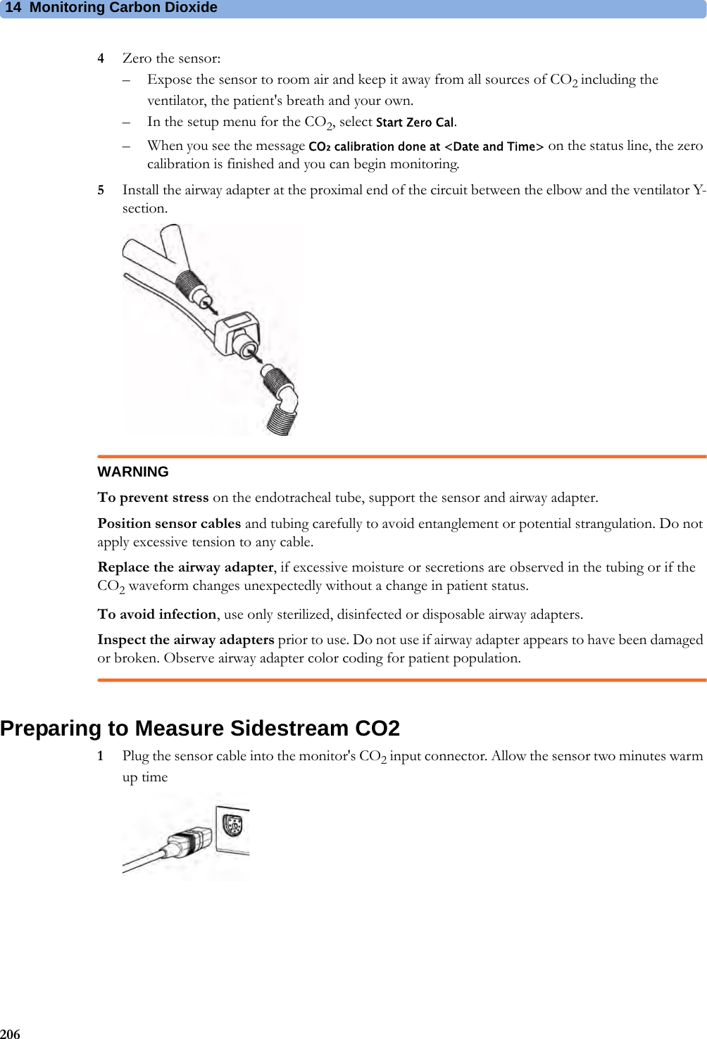
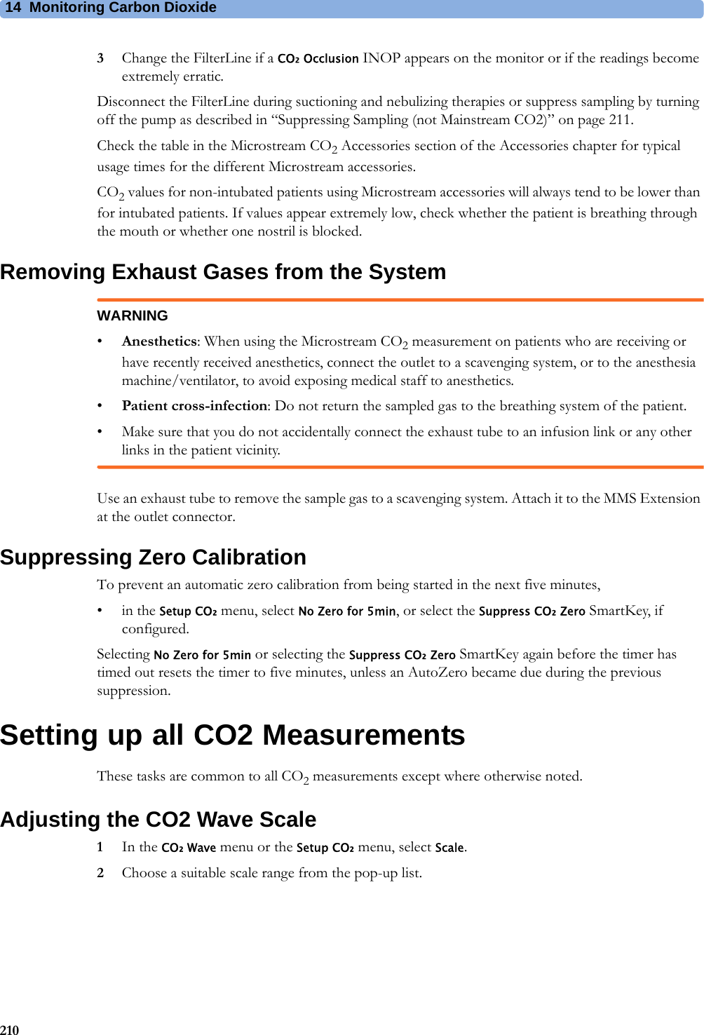
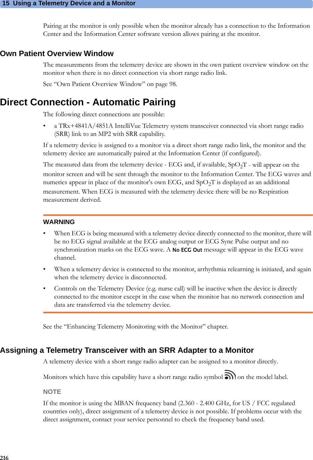
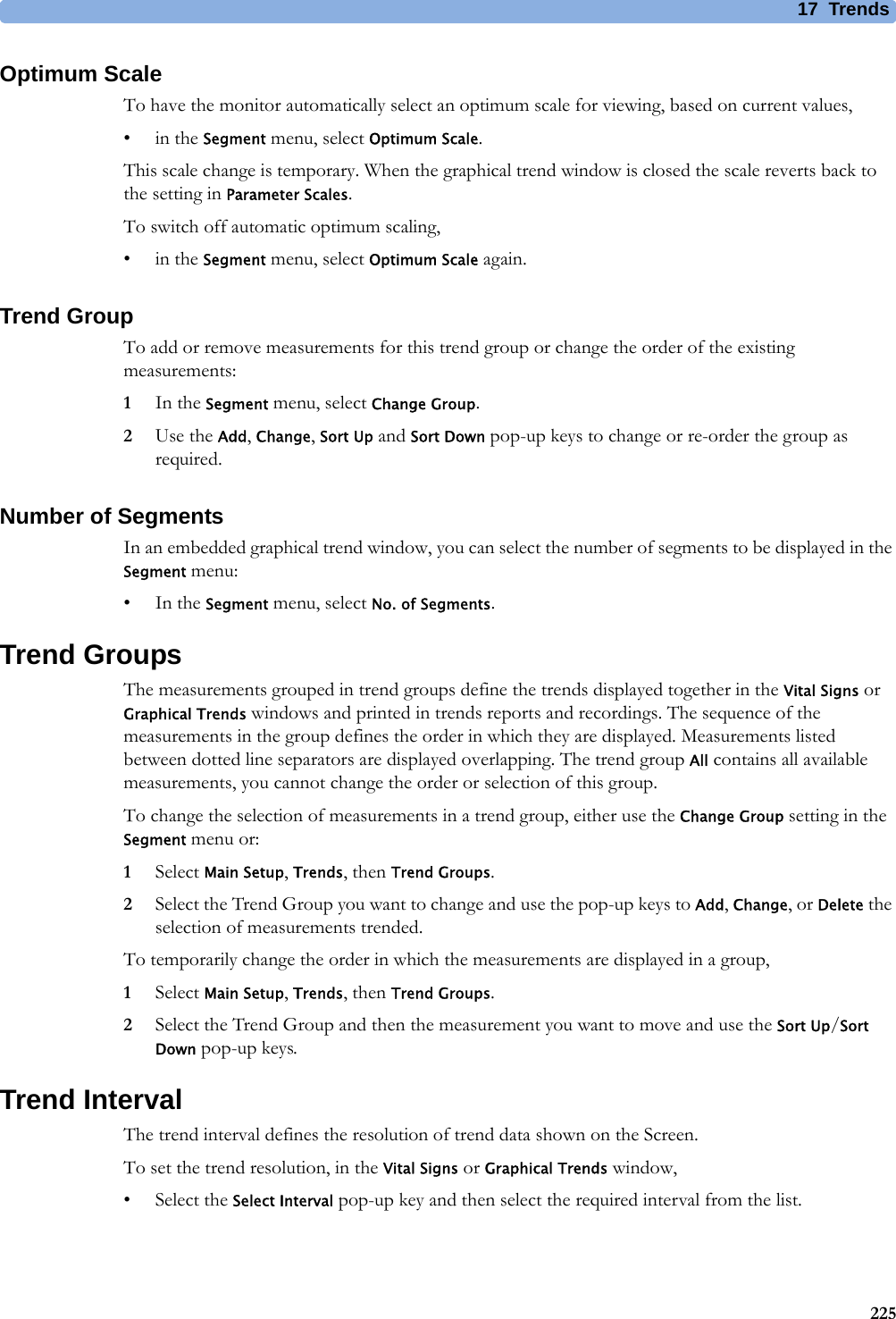
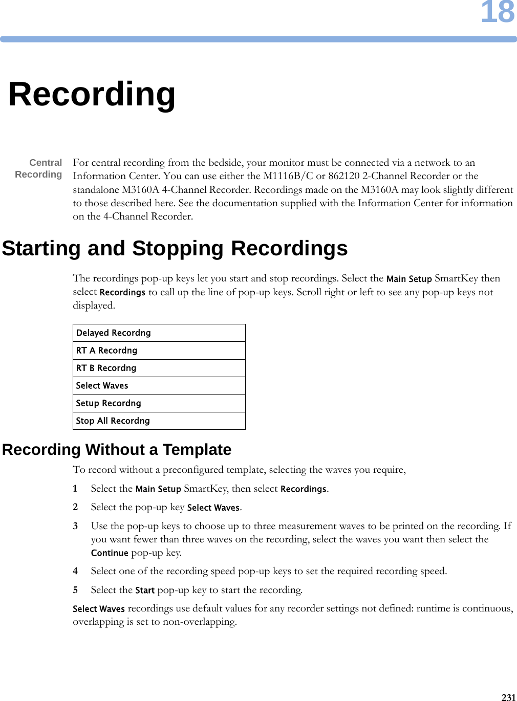
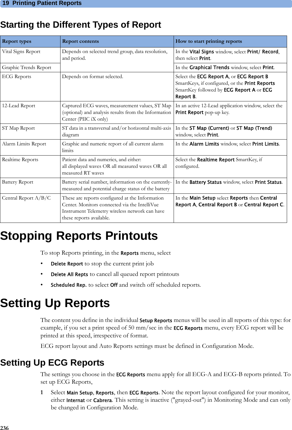
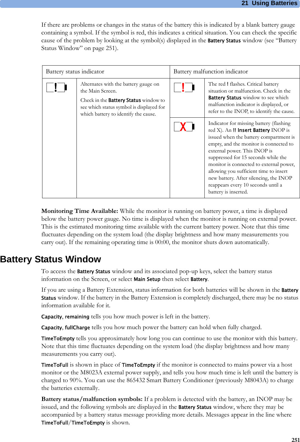
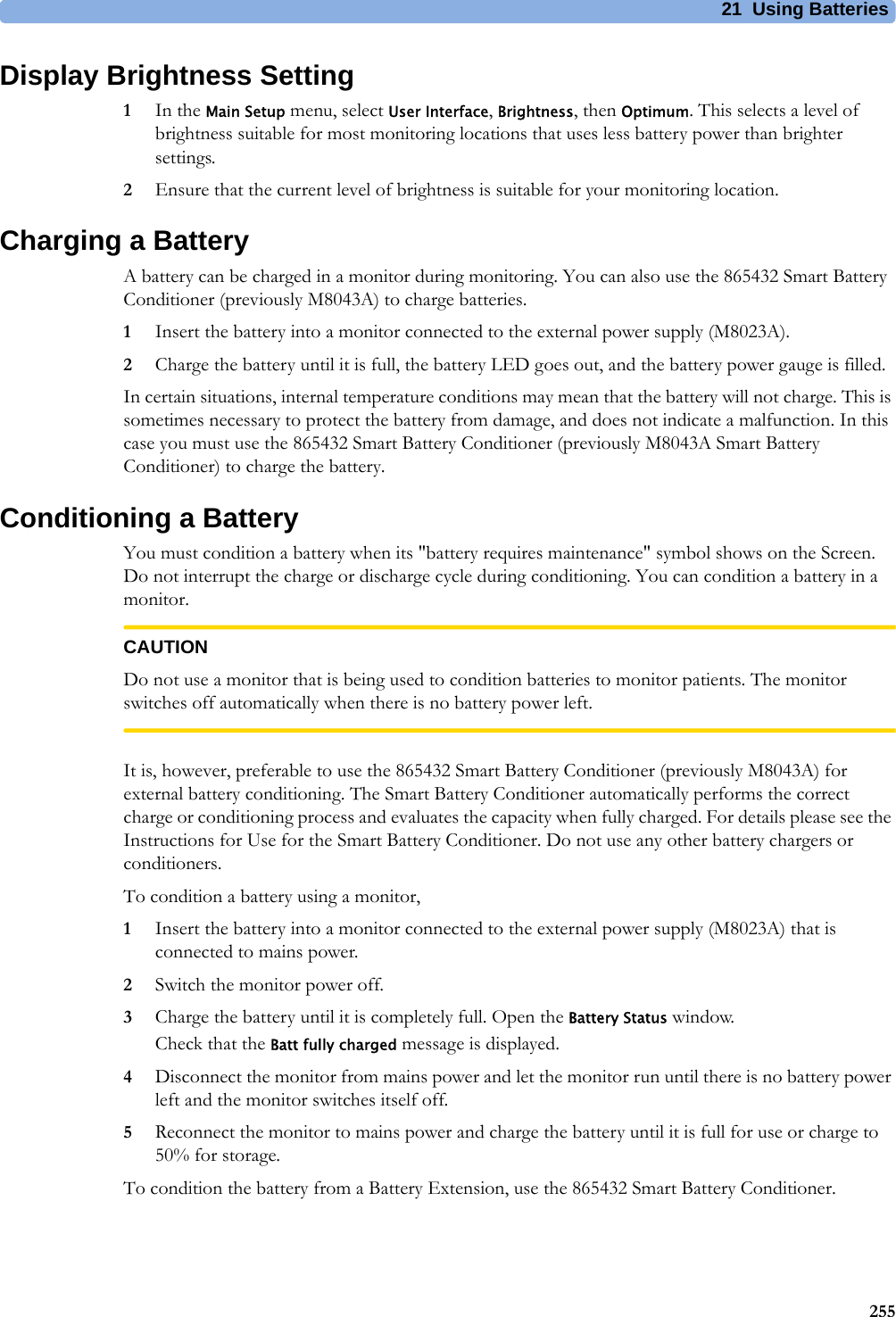
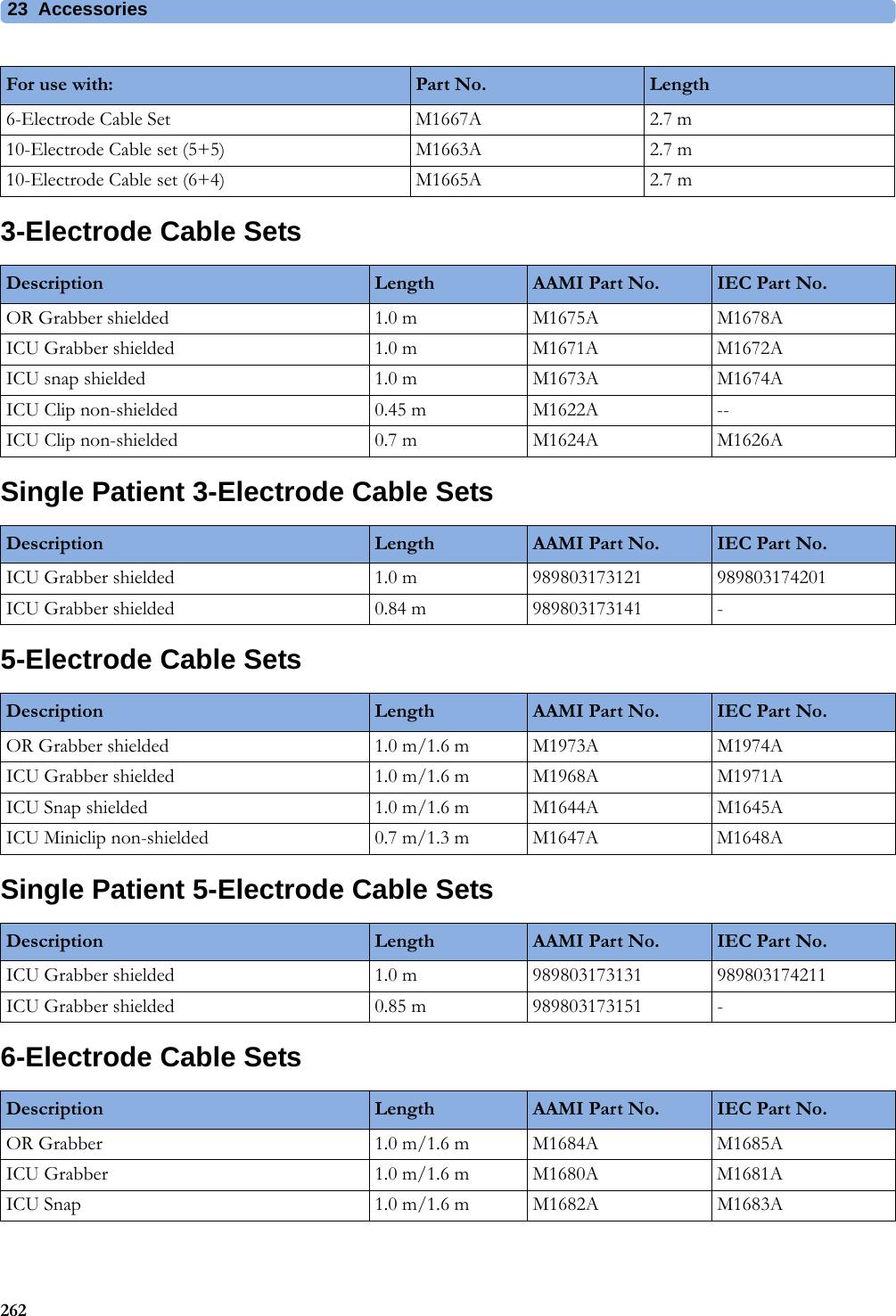
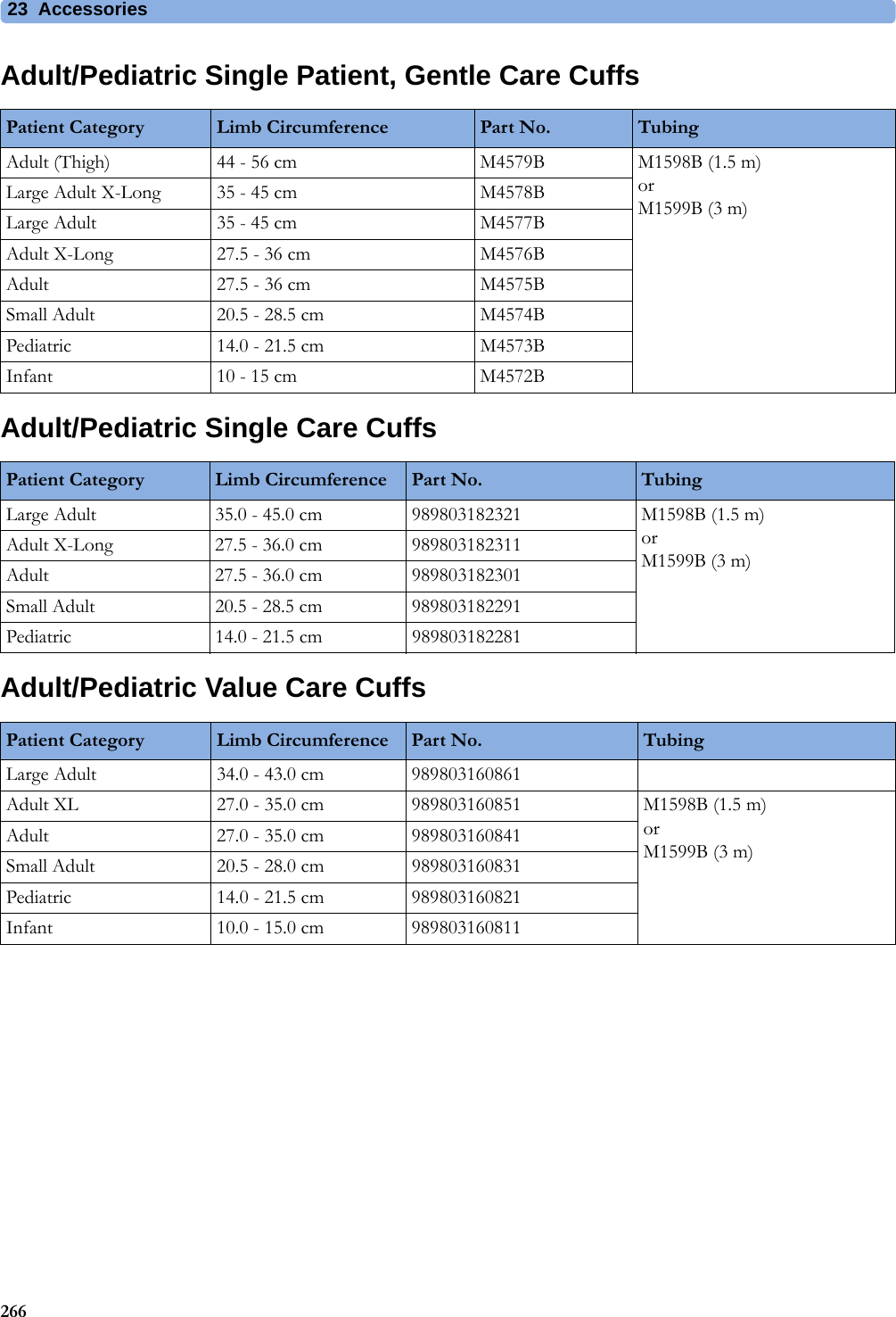
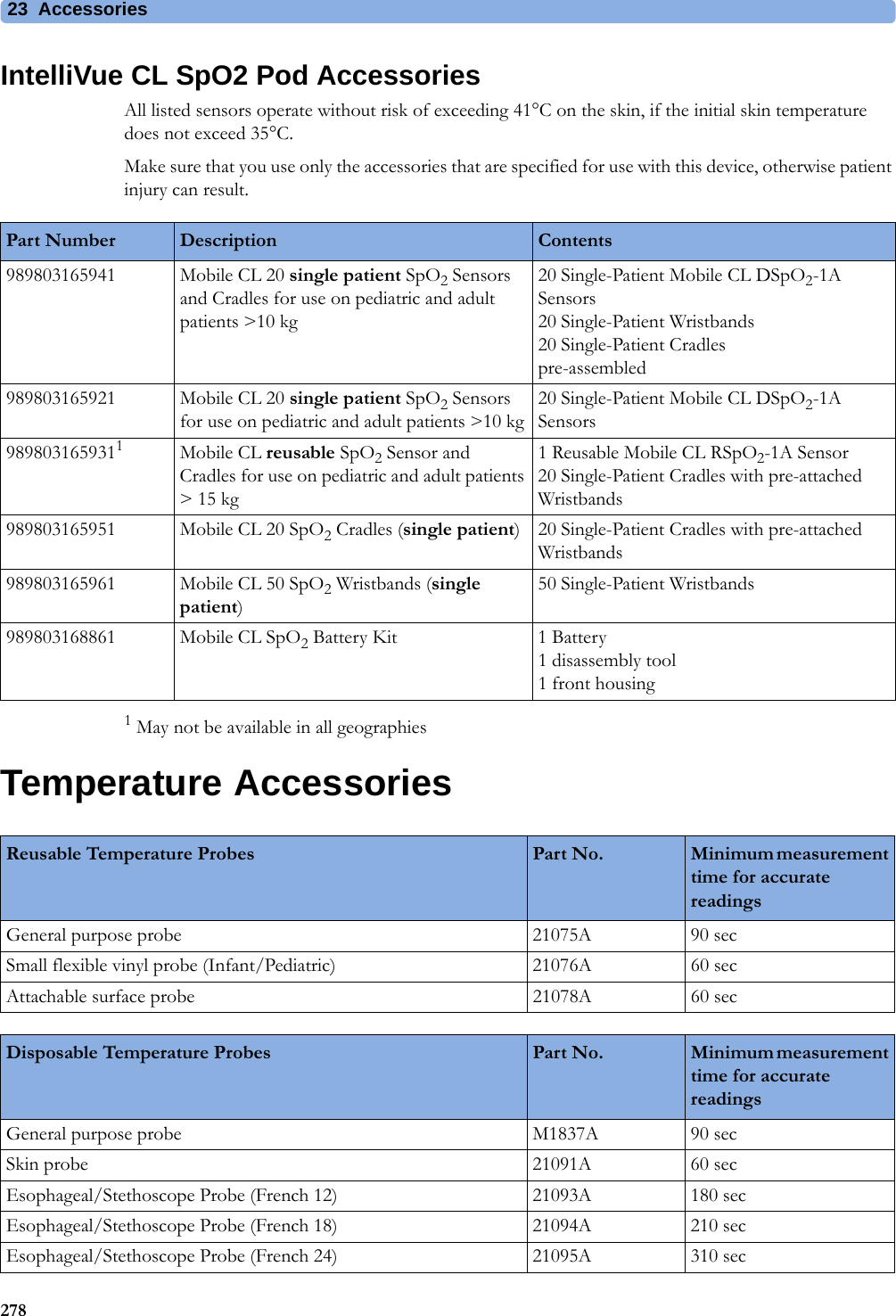
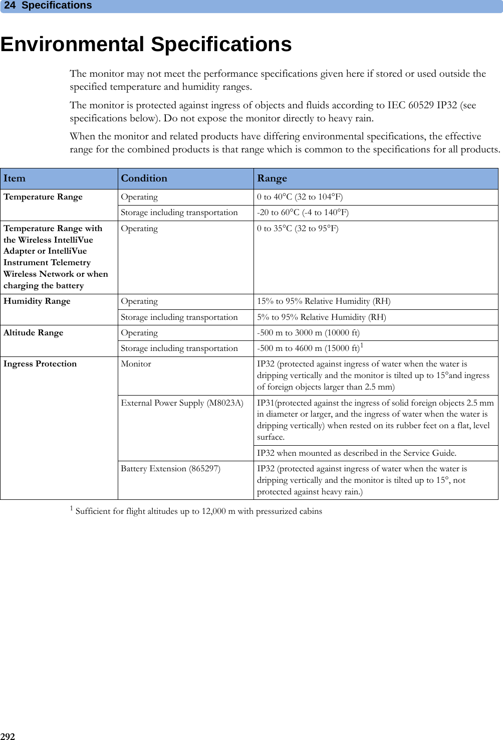
![4 Patient Alarms and INOPs73Display INOPsECG, Arrhythmia, QT and ST INOPsINOP Message, Indication What to do Indep.Dsp Malfunc. There is a problem with the Independent Display. Check the MSL coupling cable then contact your service personnel.Indep.Dsp NotSupp. The monitor does not support a second main display. The monitor software is incompatible. Contact your service personnel.Intell.Dsp Malf. There is a problem with the Intelligent Display. Check the MSL coupling cable then contact your service personnel.Intell.Dsp Missing The monitor has lost contact with the connected Intelligent Display. Contact your service personnel.Intell.Dsp Unsupp. The monitor does not support the connected Intelligent Display. The monitor software is incompatible.INOP Message, Indication What to do Cannot Analyze ECG The arrhythmia algorithm cannot reliably analyze the ECG data. Check the ECG signal quality of the selected primary and secondary leads. If necessary, improve lead position or reduce patient motion.Cannot Analyze QT The QT algorithm cannot generate a valid QT value for more than 10 minutes, or 1 minute in the initial phase.Cannot Analyze ST The ST algorithm cannot generate a valid ST value. Possible causes are large variations in the measured ST values for consecutive beats, or ventricular paced beats. Review the ECG signal quality and the ST measurement points. If the patient has a ventricular pacemaker, ST analysis is not possible.Cannot Analyze STE The STE algorithm cannot generate valid ST elevation values. Possible causes are large variations in the measured ST values for consecutive beats, or ventricular paced beats. Review the ECG signal quality and the ST measurement points.ECG Equip MalfNumeric is replaced by -?-INOP toneContact your service personnel.The ECG hardware is faulty.<ECG Lead> Lead Off!! <ECG Lead> Lead Off!!! <ECG Lead> Lead OffIf no ECG lead is measurable, numeric is replaced by -?-INOP toneNot all the required leads for ECG monitoring are connected. Check the ECG connections and make sure that the electrode indicated by <ECG lead> is attached [e.g. RA, LA, LL, RL, V or C electrodes]. With EASI lead placement all 5 electrodes must be connected, and with Hexad lead placement all 6 electrodes must be connected.ECG Leads Off!! ECG Leads Off!!!ECG Leads OffNumeric is replaced by -?-INOP toneCheck that all of the required ECG leads are attached, and that none of the electrodes have been displaced. The INOP may also be caused by a saturated or overloaded ECG amplifier.ECG Noisy Elec <ECG Lead> The ECG signal from the named ECG electrodes [RA, LA, LL, RL, V (or C)] is noisy. Check the ECG connections and make sure that the electrode indicated is attached.ECG Noisy SignalINOP toneThe ECG signal is too noisy. Check that the electrodes are properly placed and have not dried out. Remove any possible sources of signal noise (such as power cords) from the area around the cable and the patient.The ECG signal may be saturated or overloaded.ECG Out Equip MalfINOP toneThere is a problem with the device connected to the ECG Out connector. Contact your service personnel.ECG/Arrh AlarmsOff!!ECG/Ar AlarmsOffAll ECG alarms have been switched off, or the HR alarm source is not ECG. To resume ECG alarm generation, switch ECG alarms on or select ECG as the alarm source.](https://usermanual.wiki/Philips-Medical-Systems-North-America/WLANBV3.user-manual-mp2-english/User-Guide-3422182-Page-73.png)
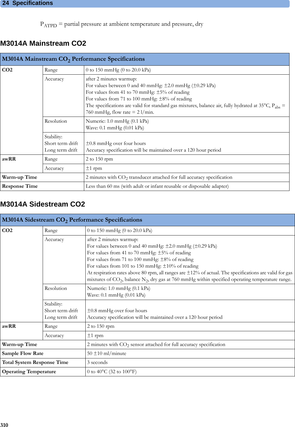
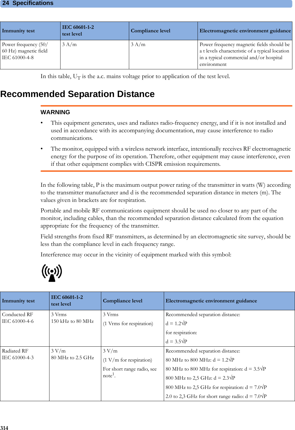
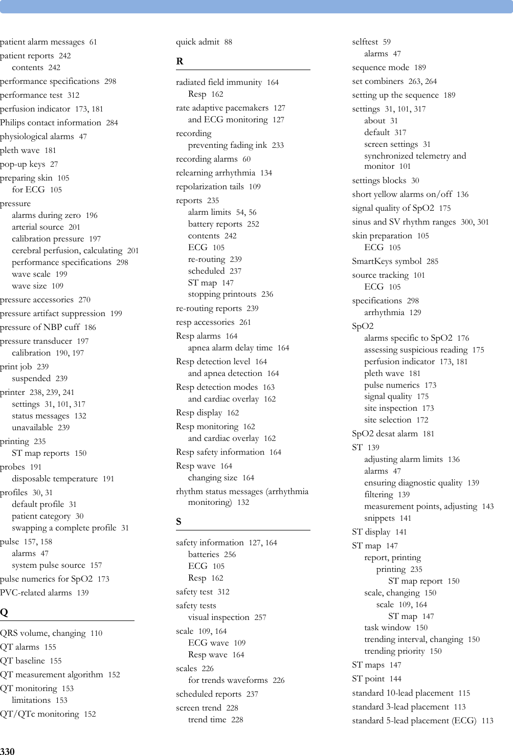
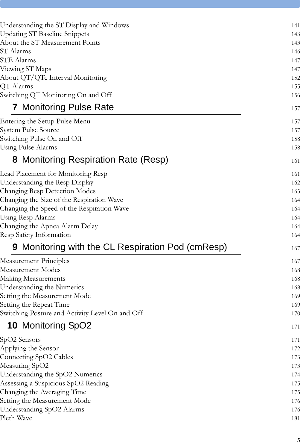
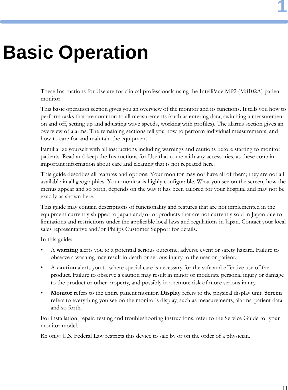
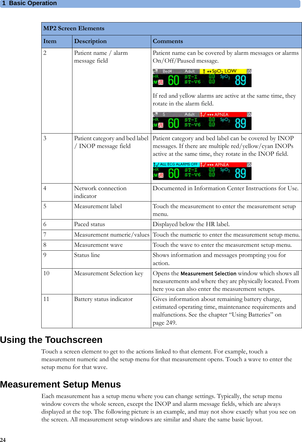
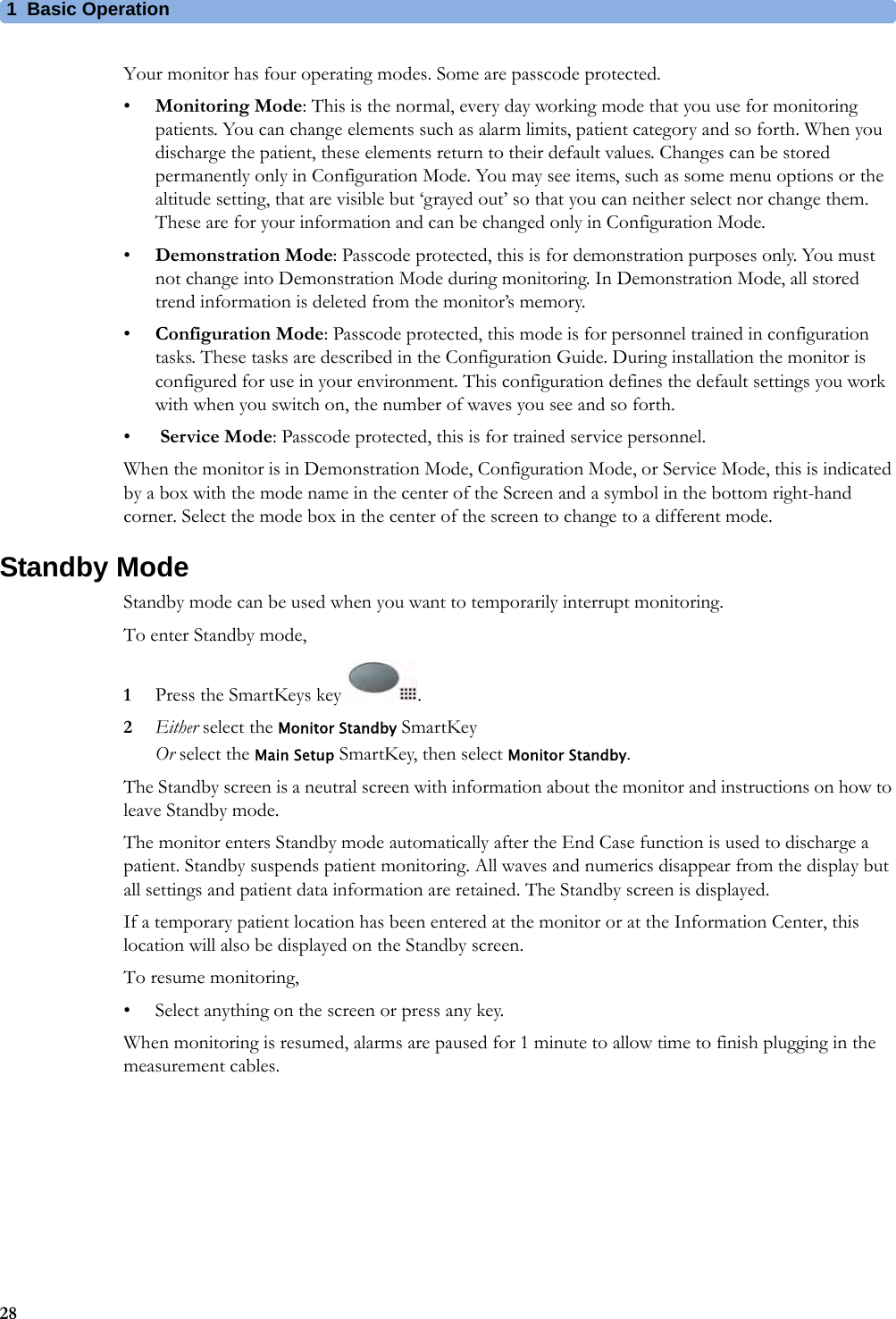
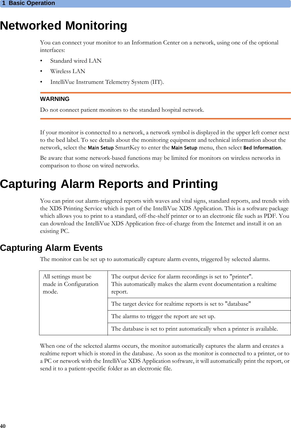
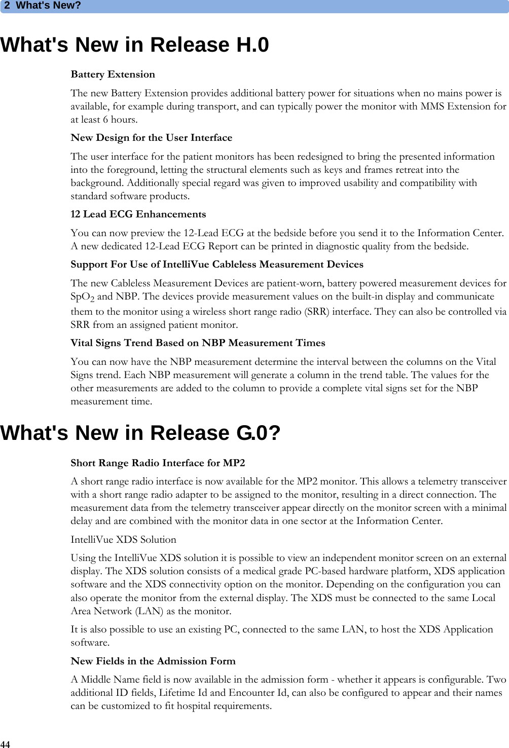
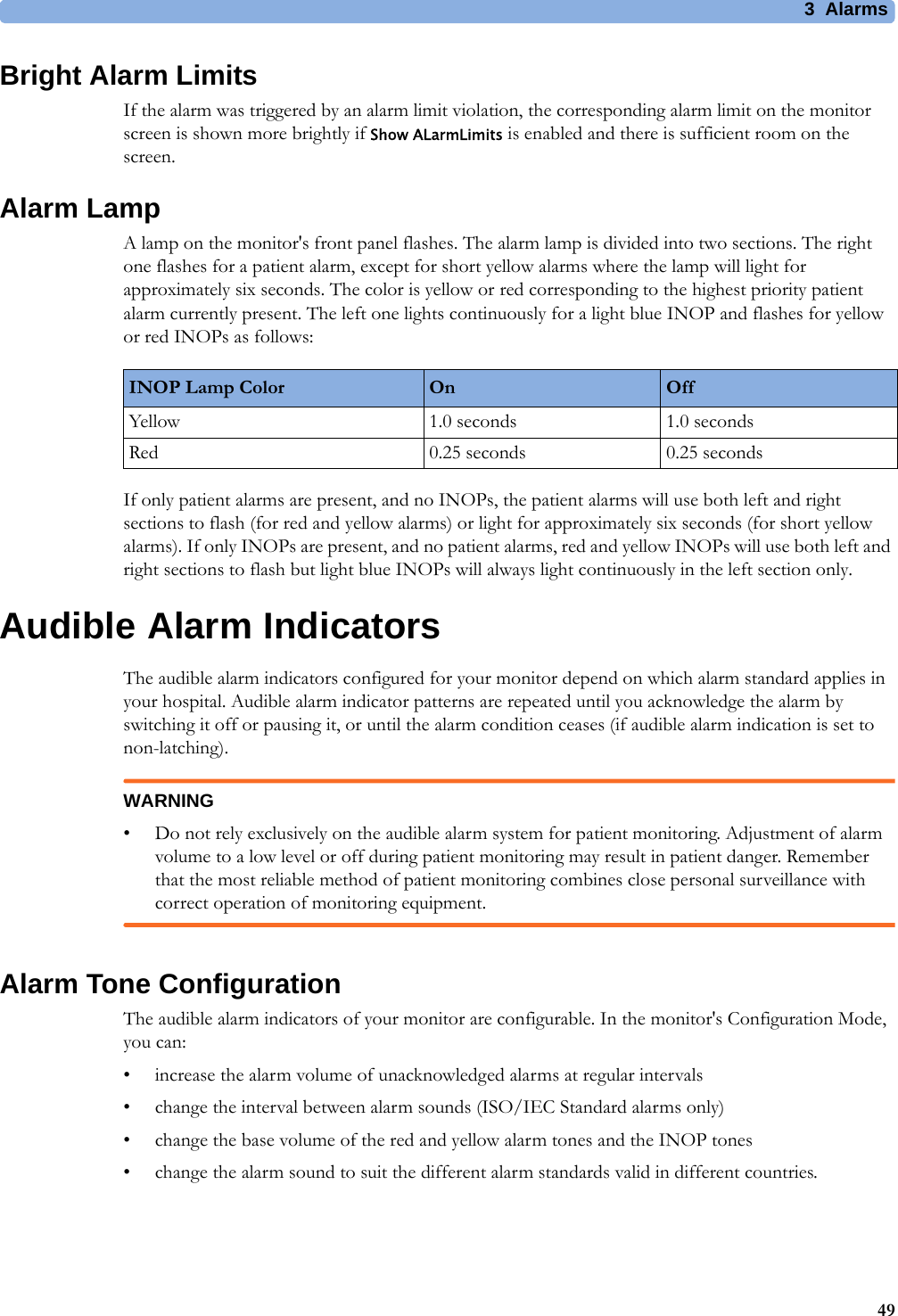
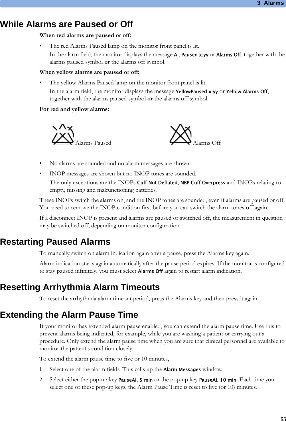
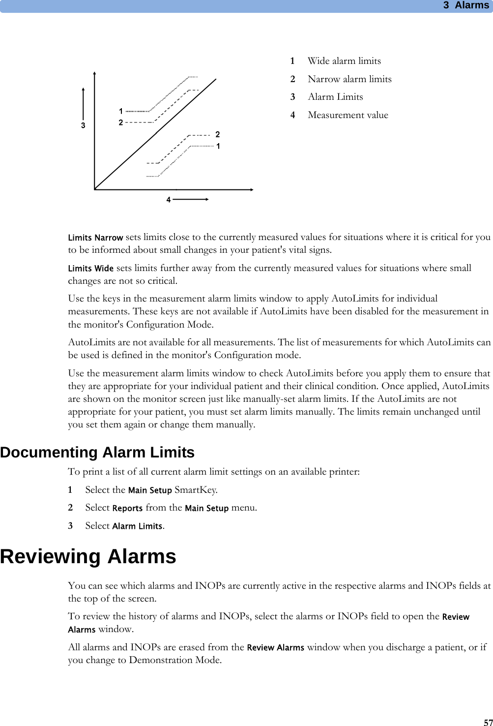
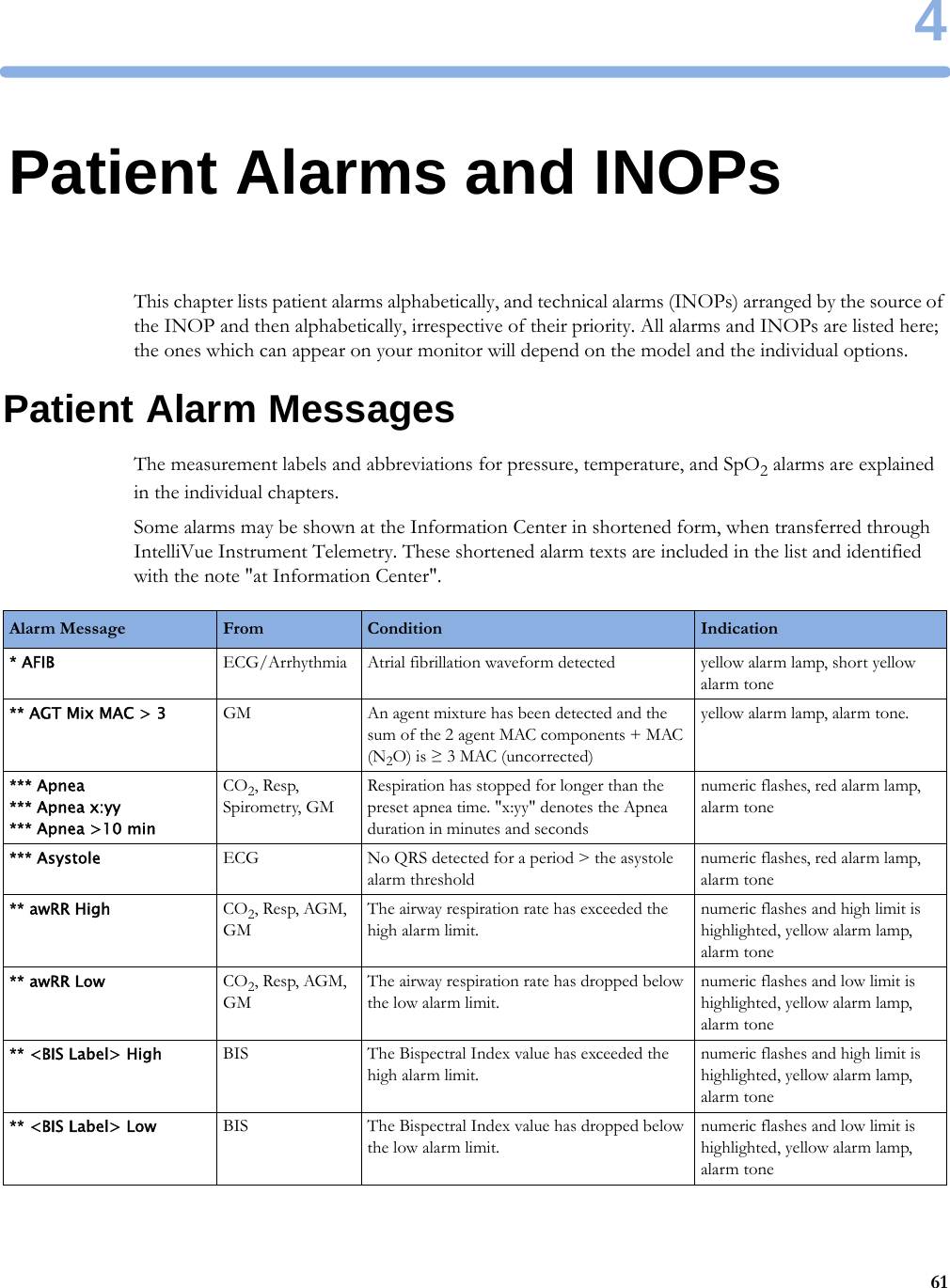
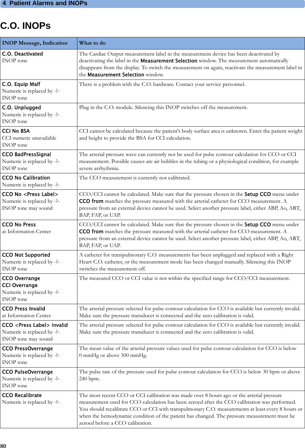
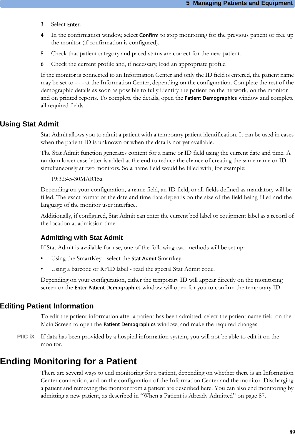
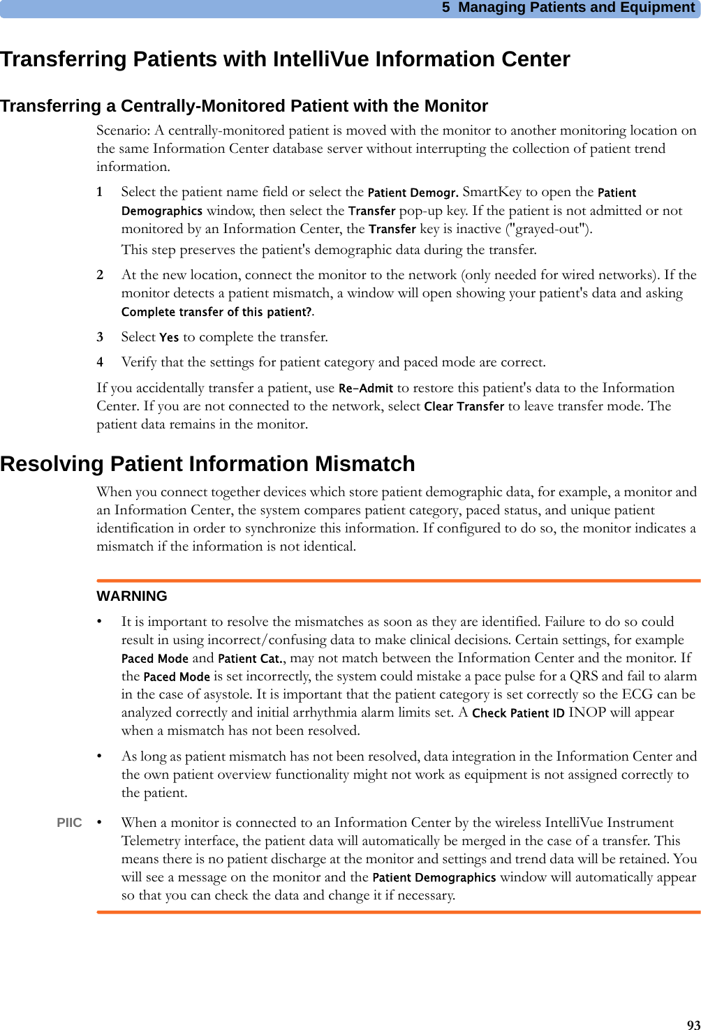
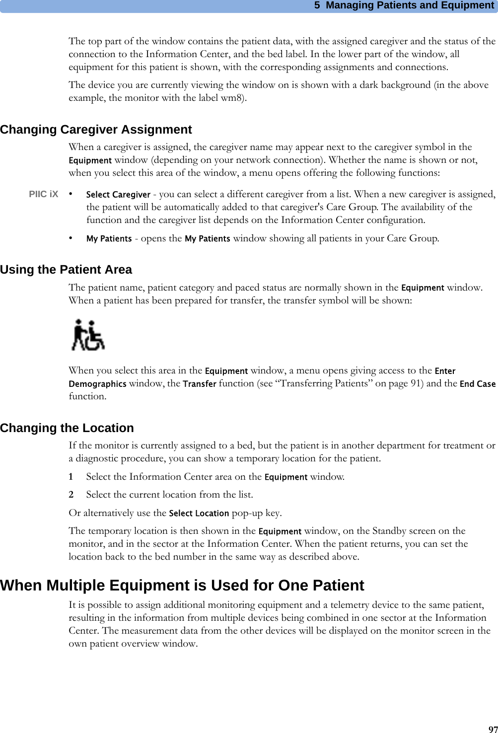
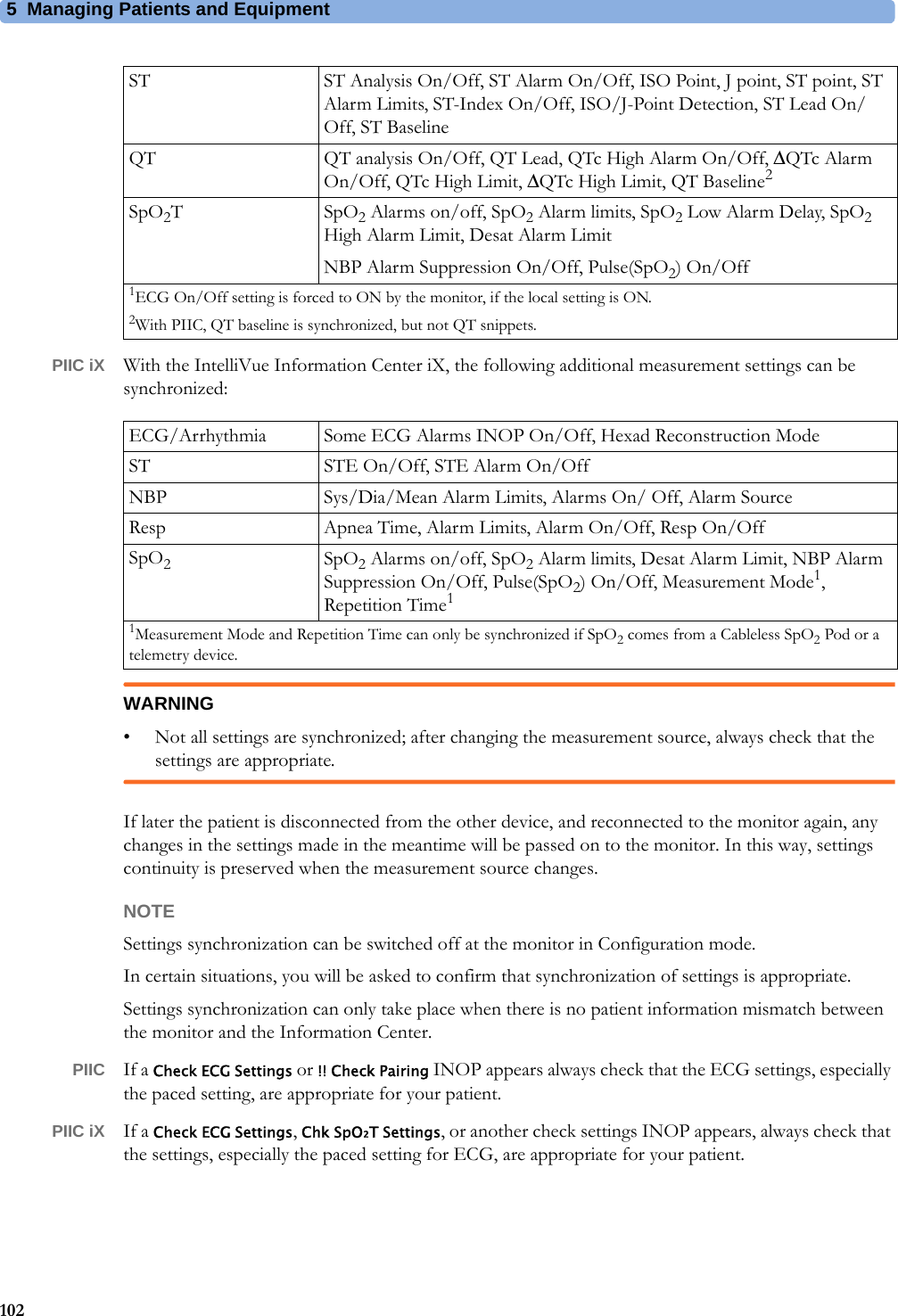
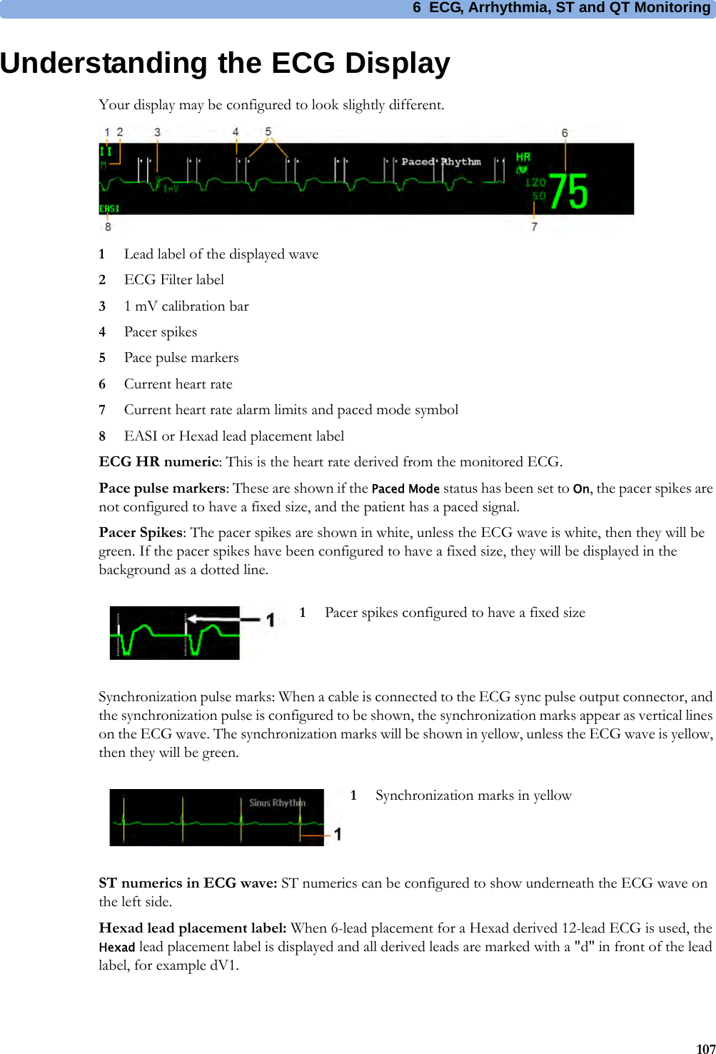
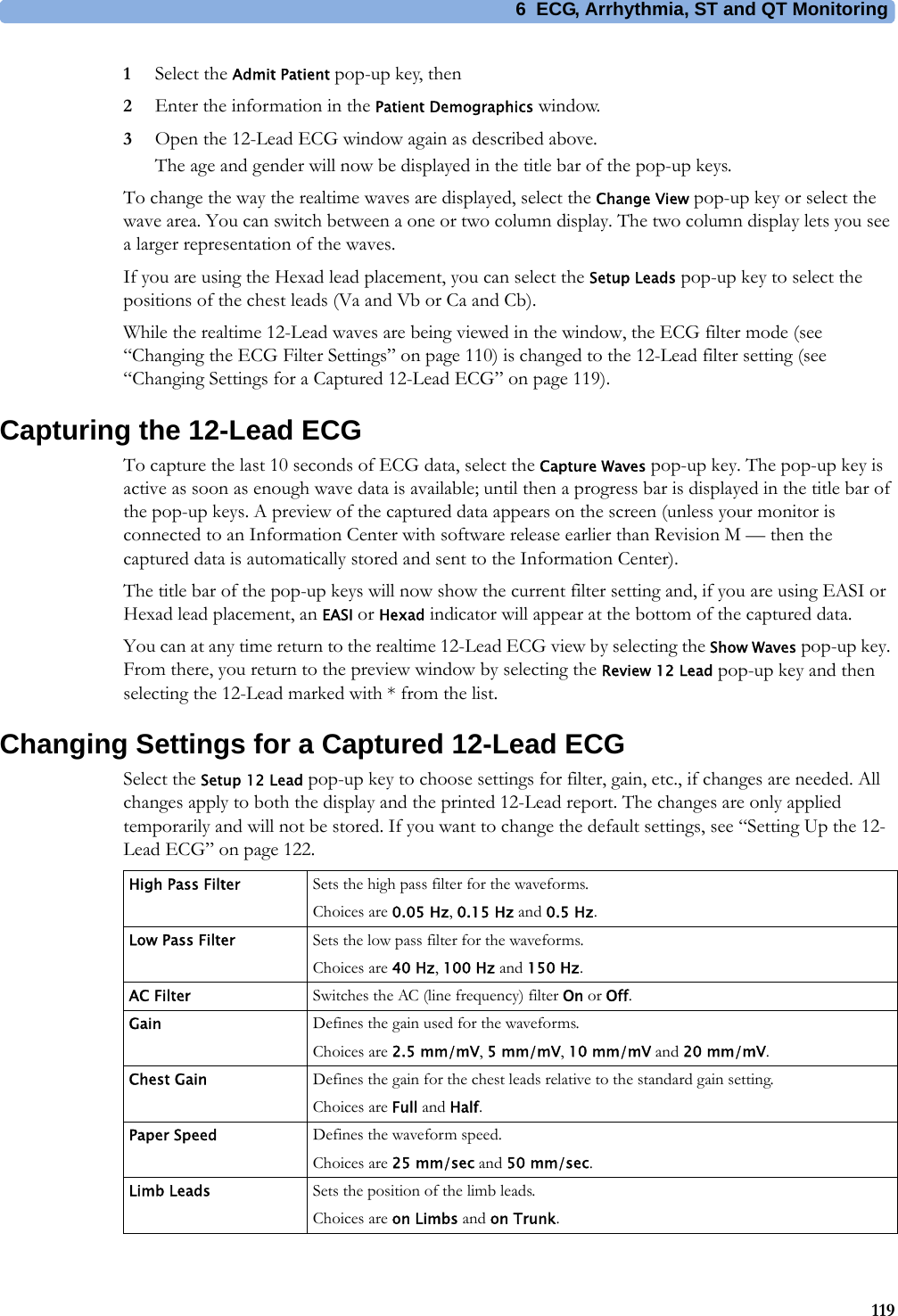
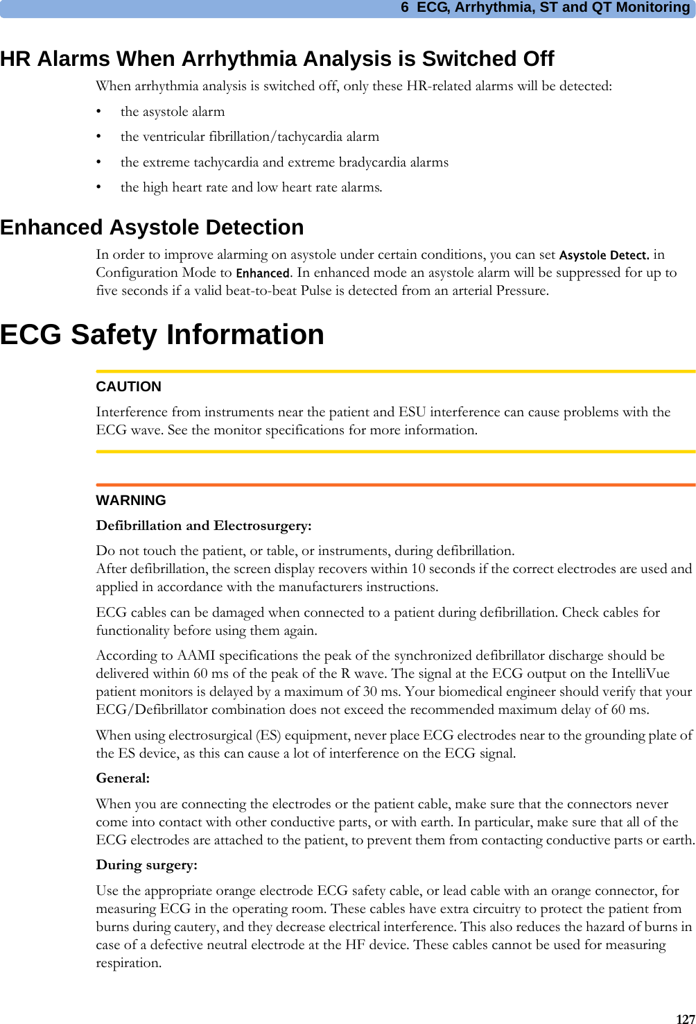
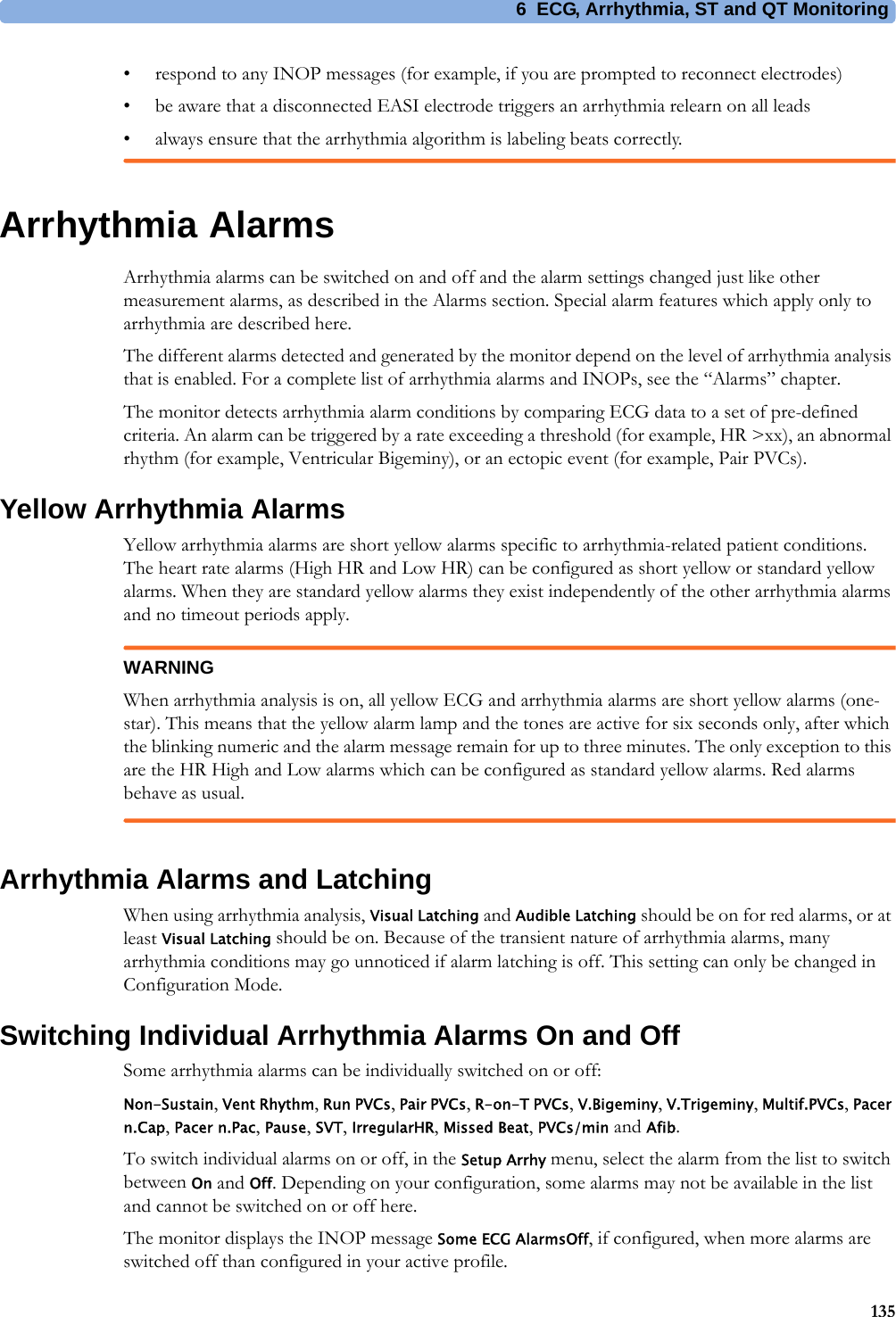
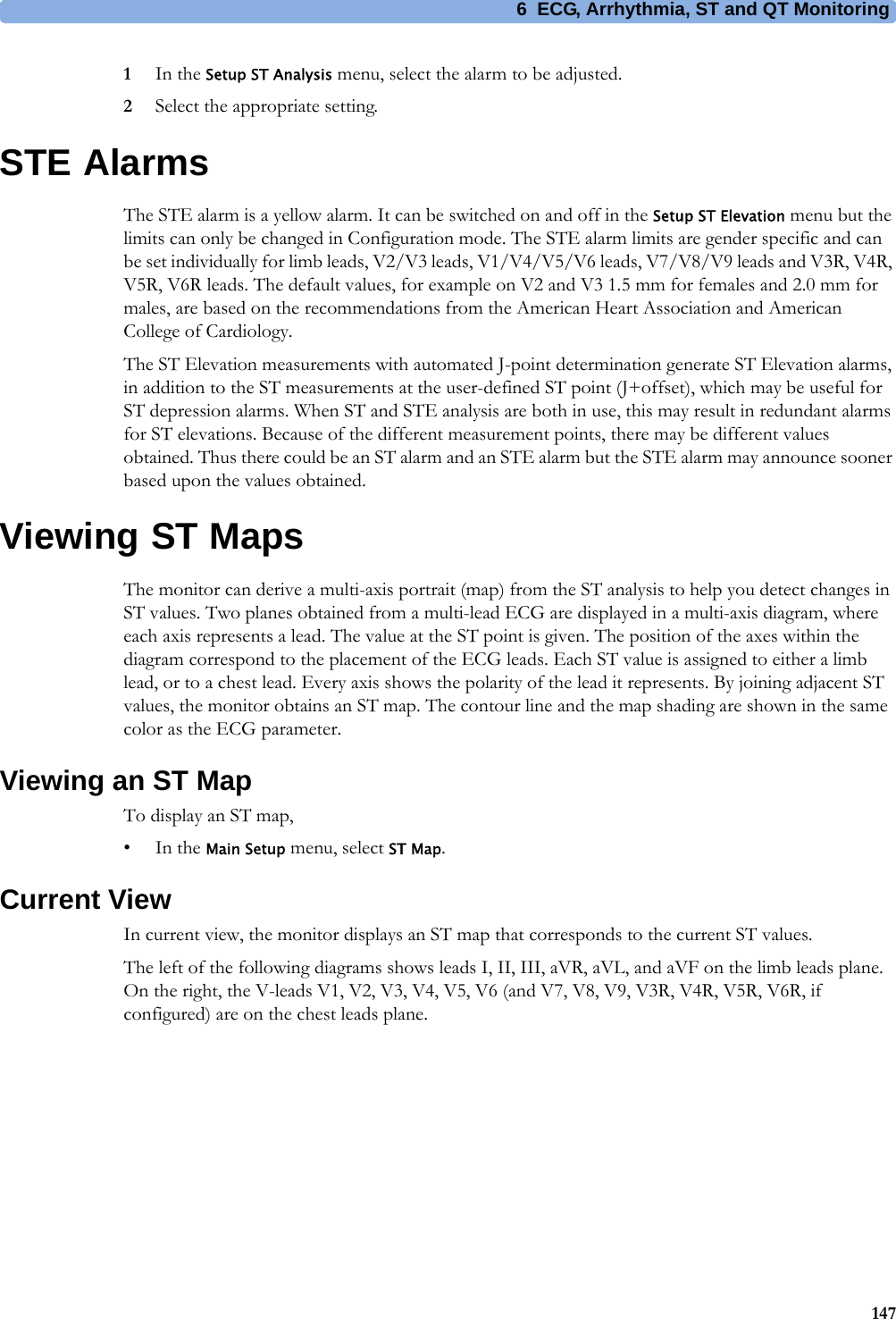
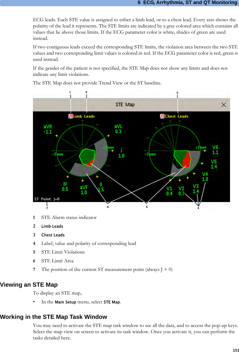
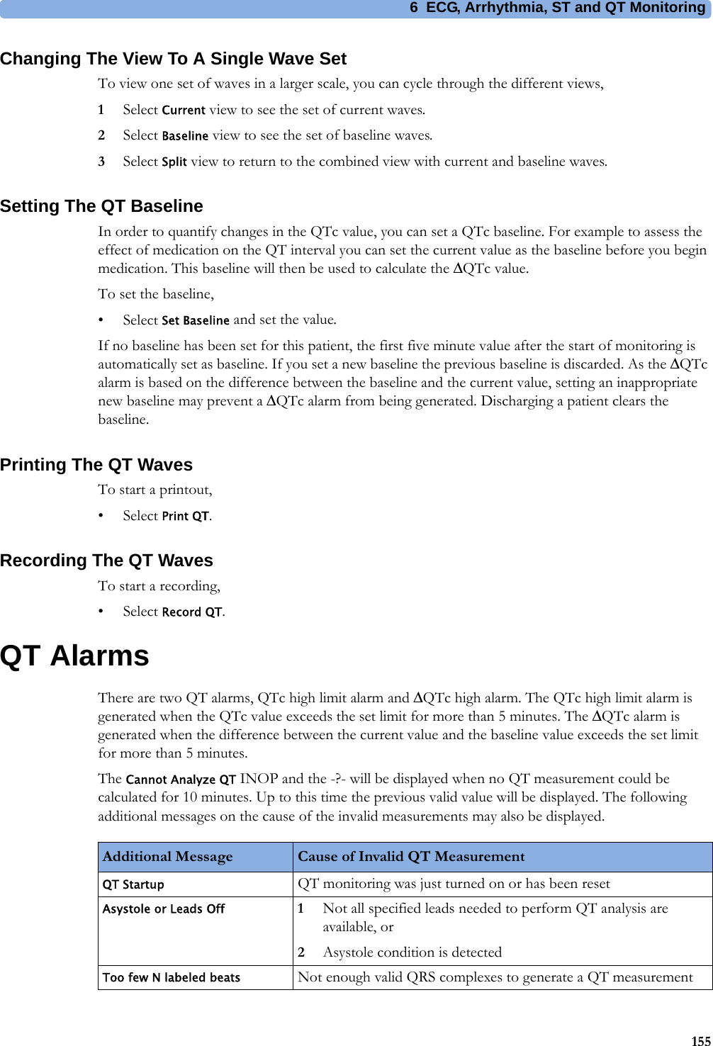
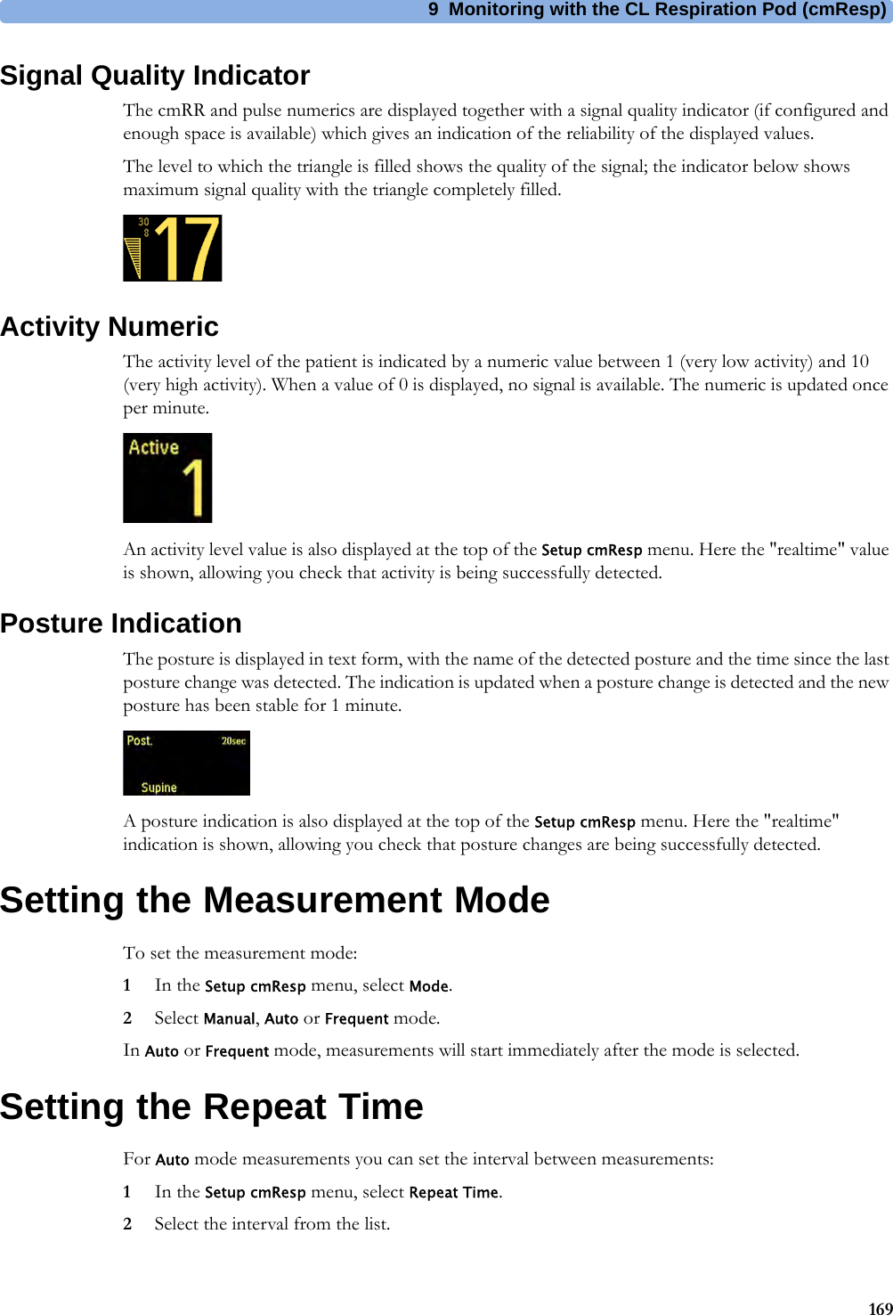
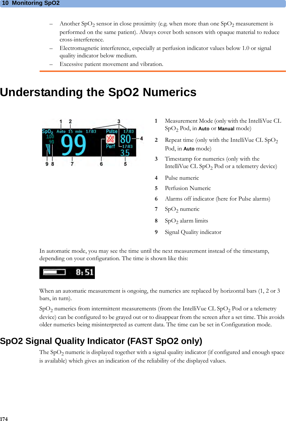
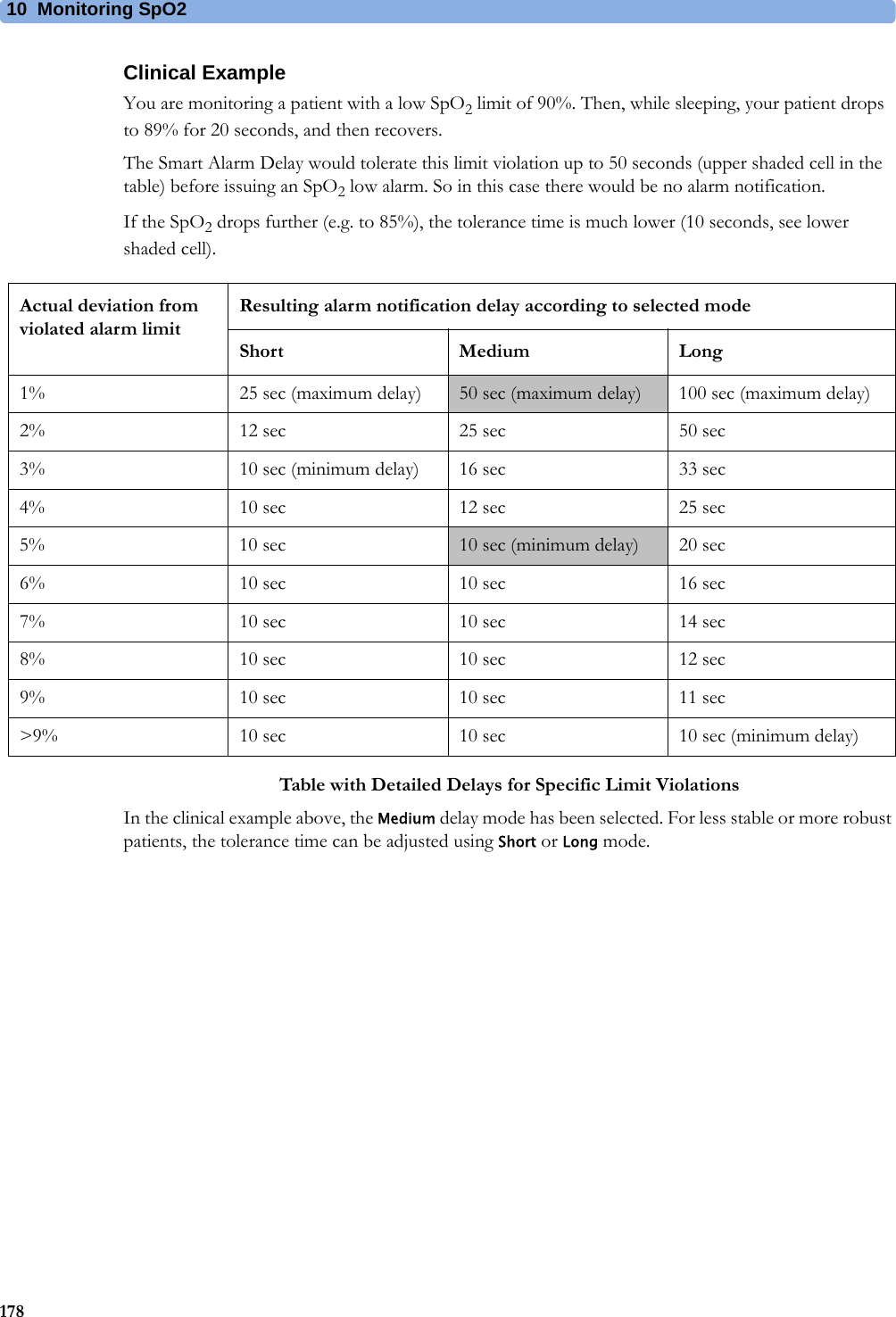
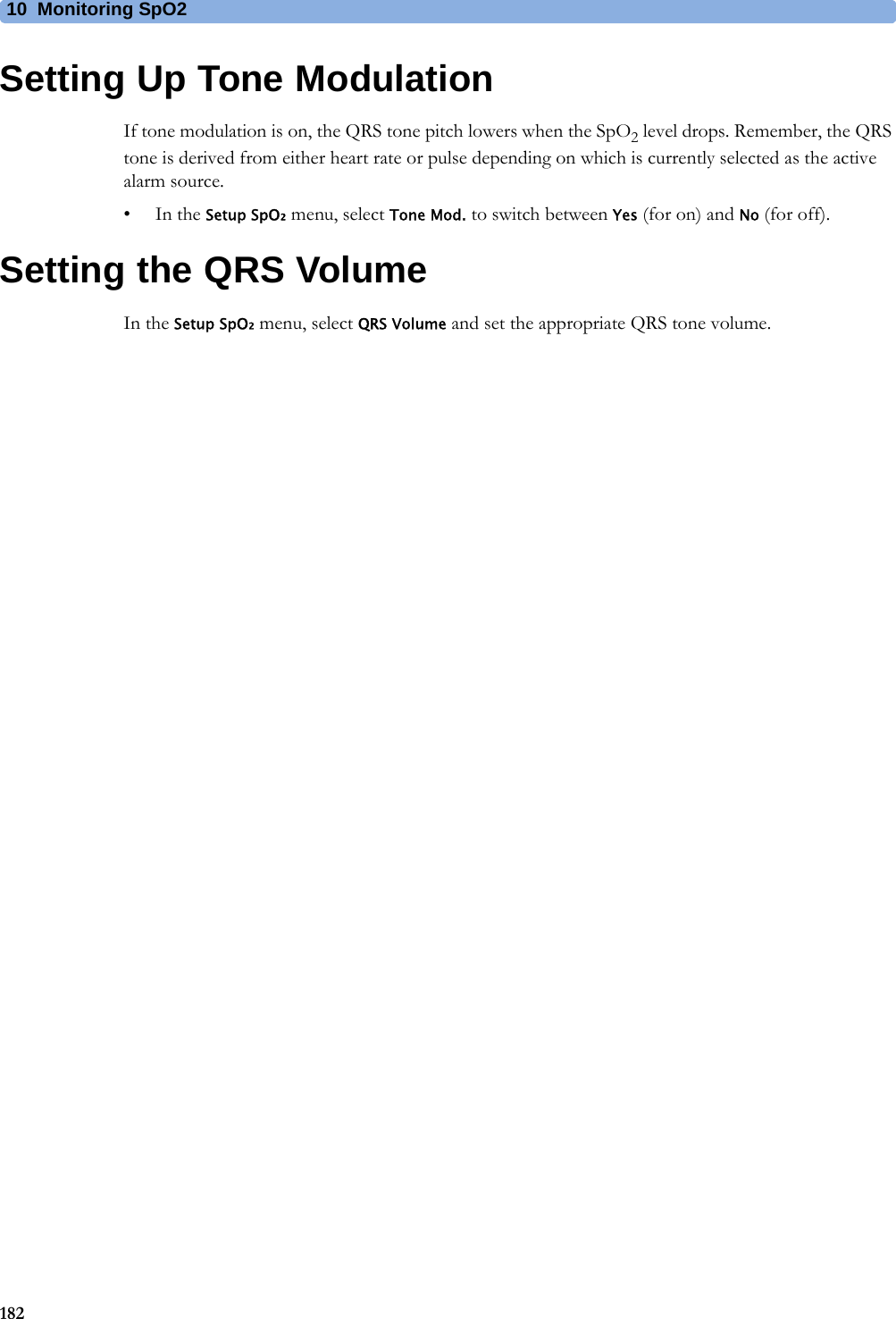
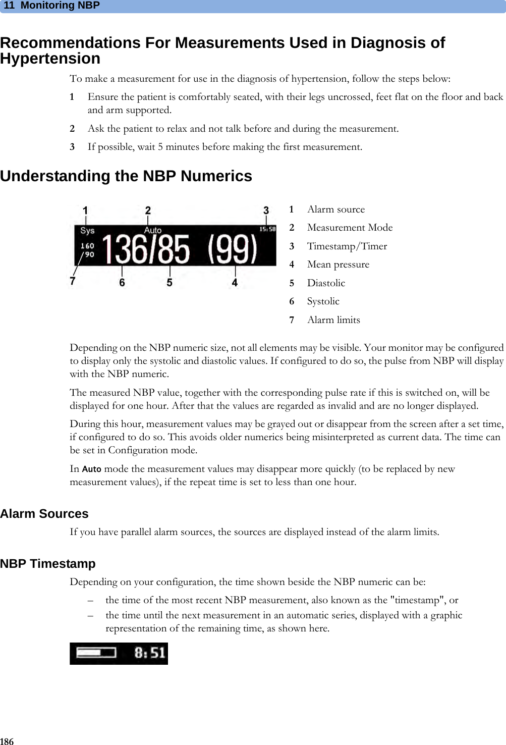
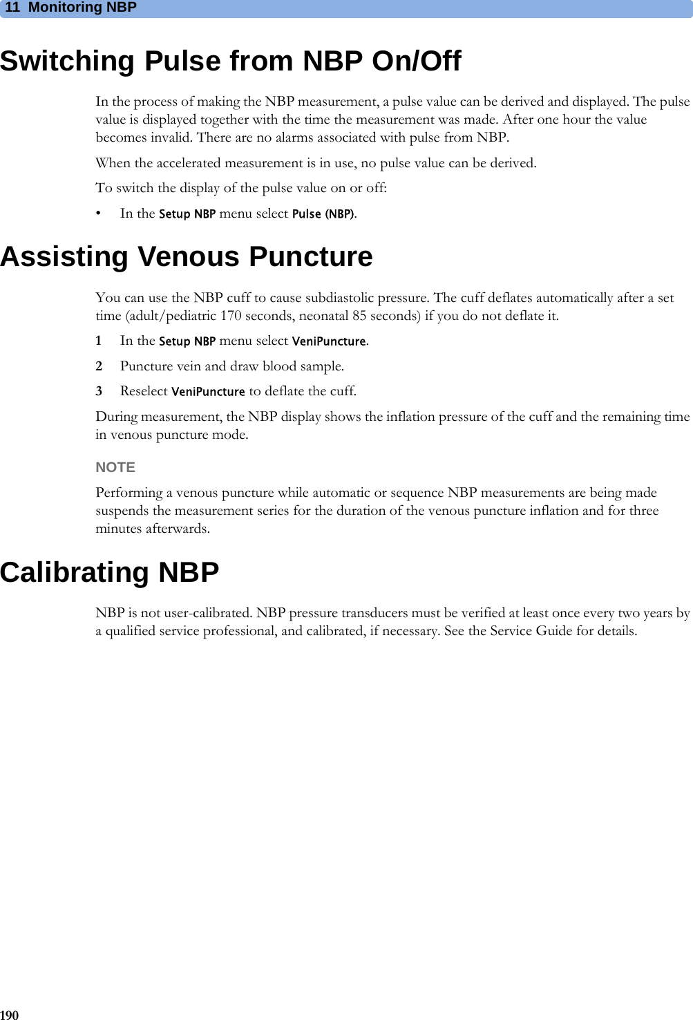
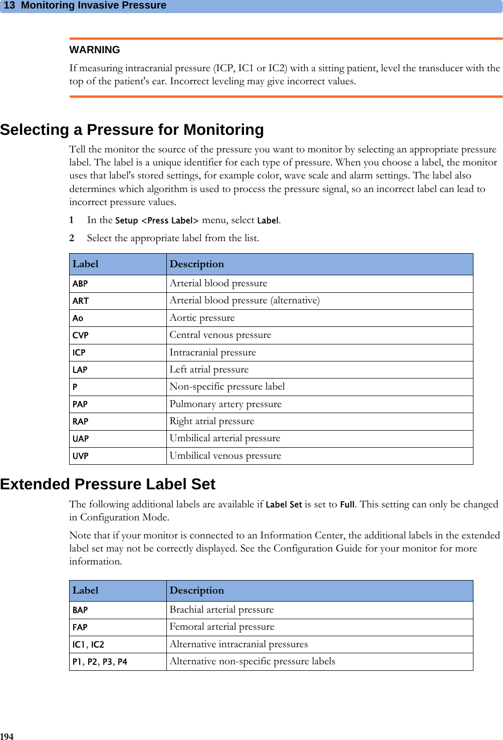
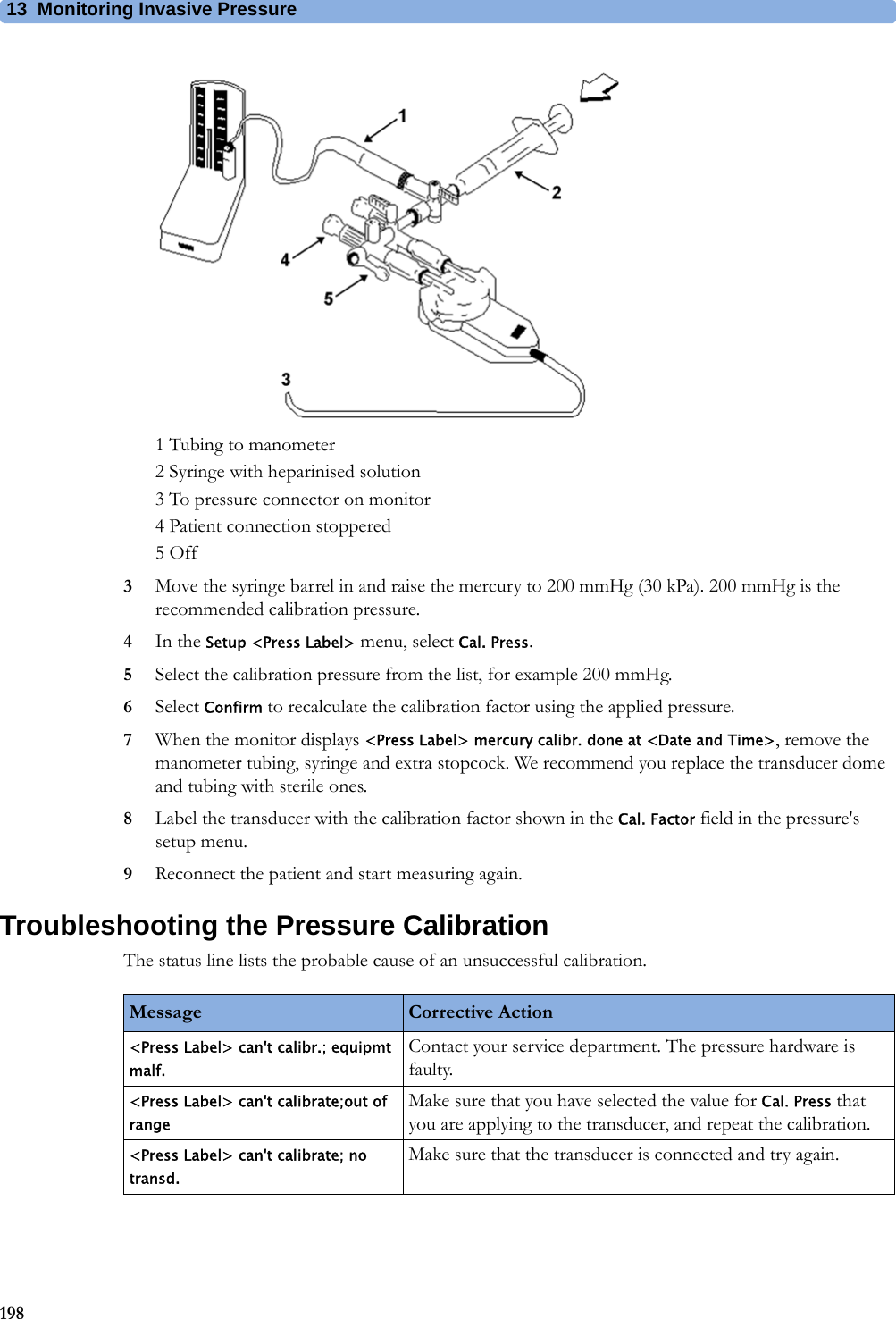
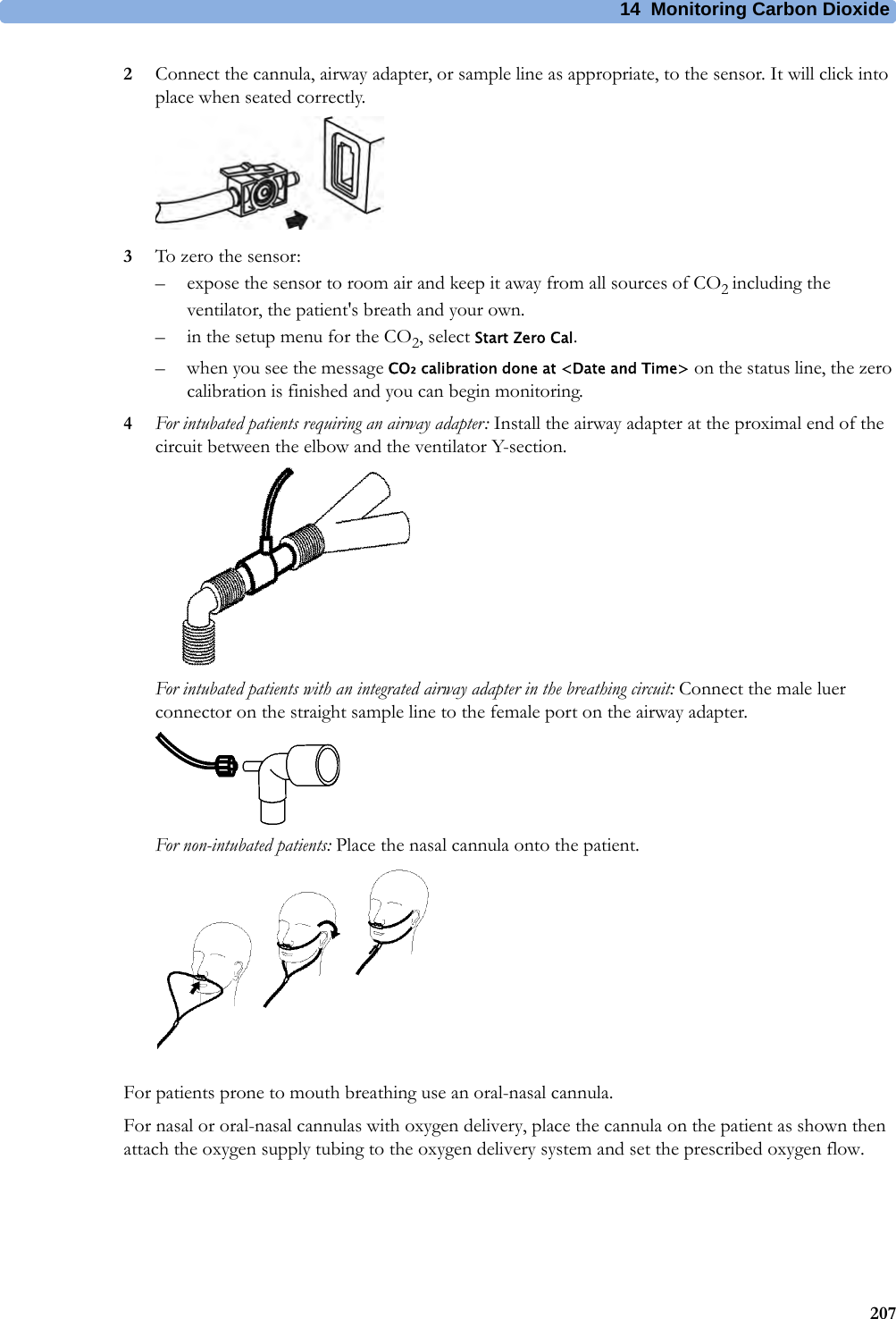
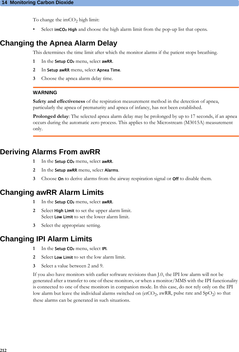
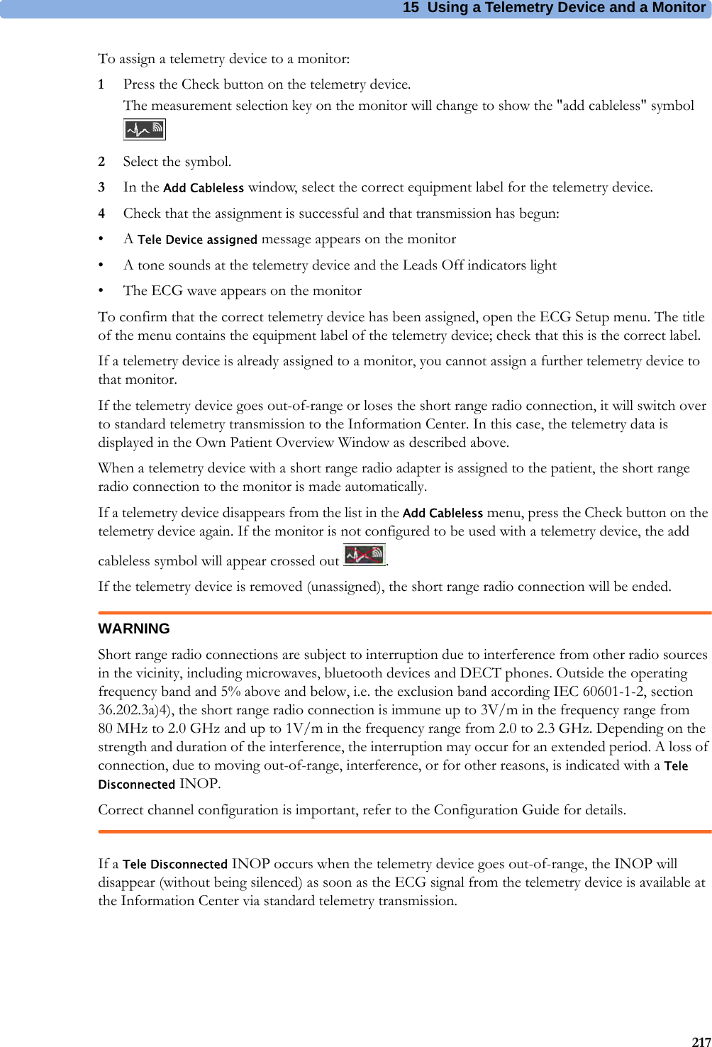
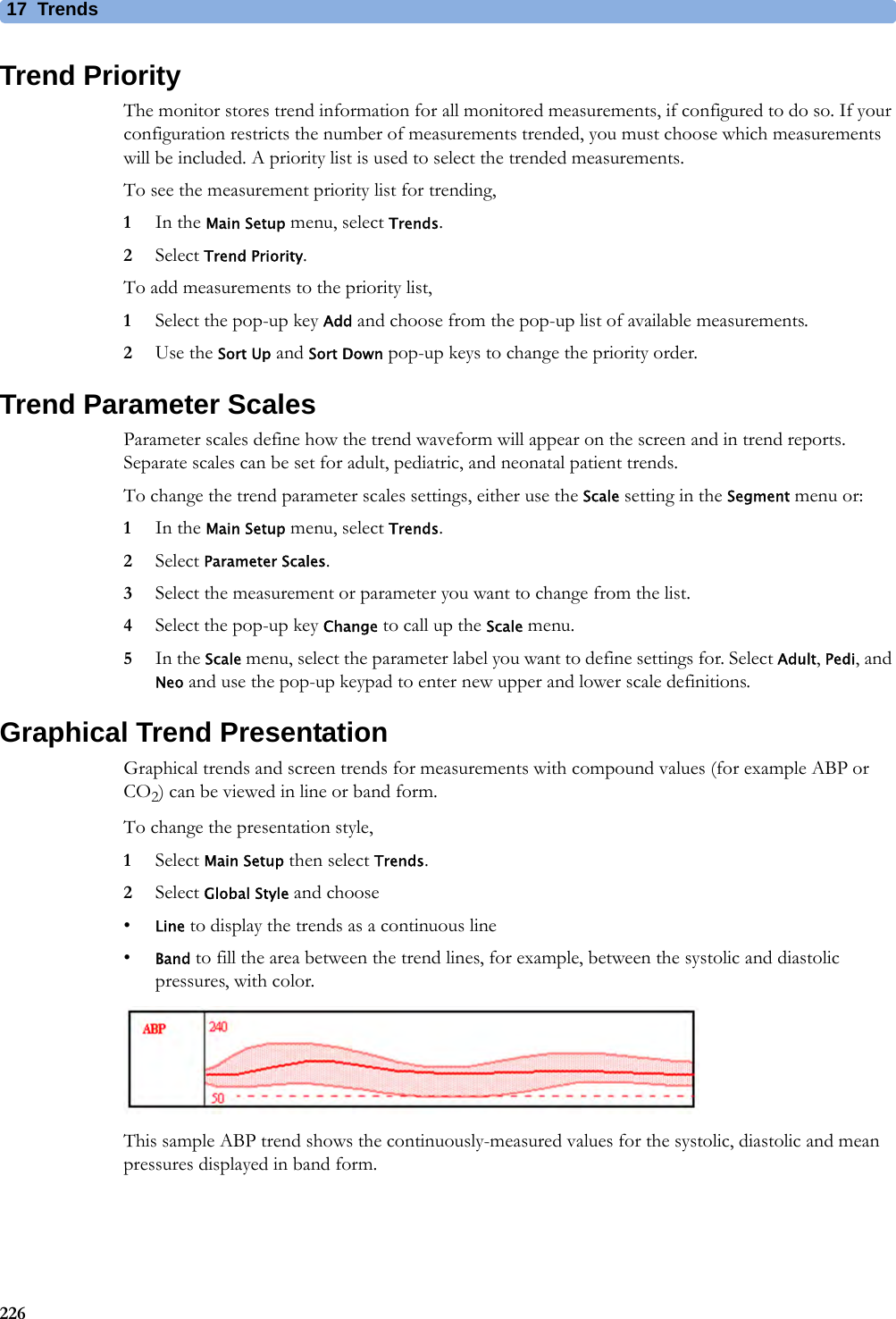
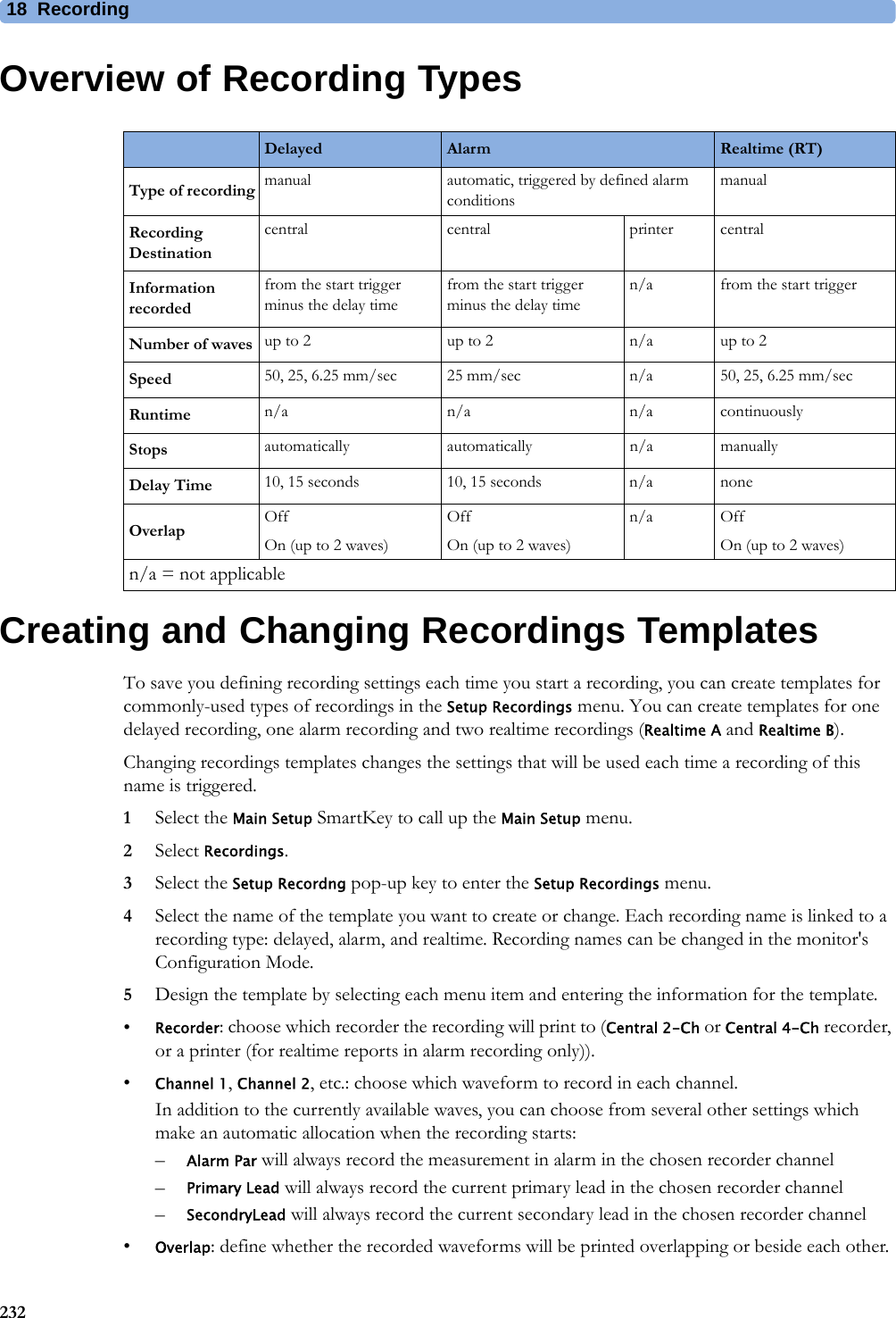
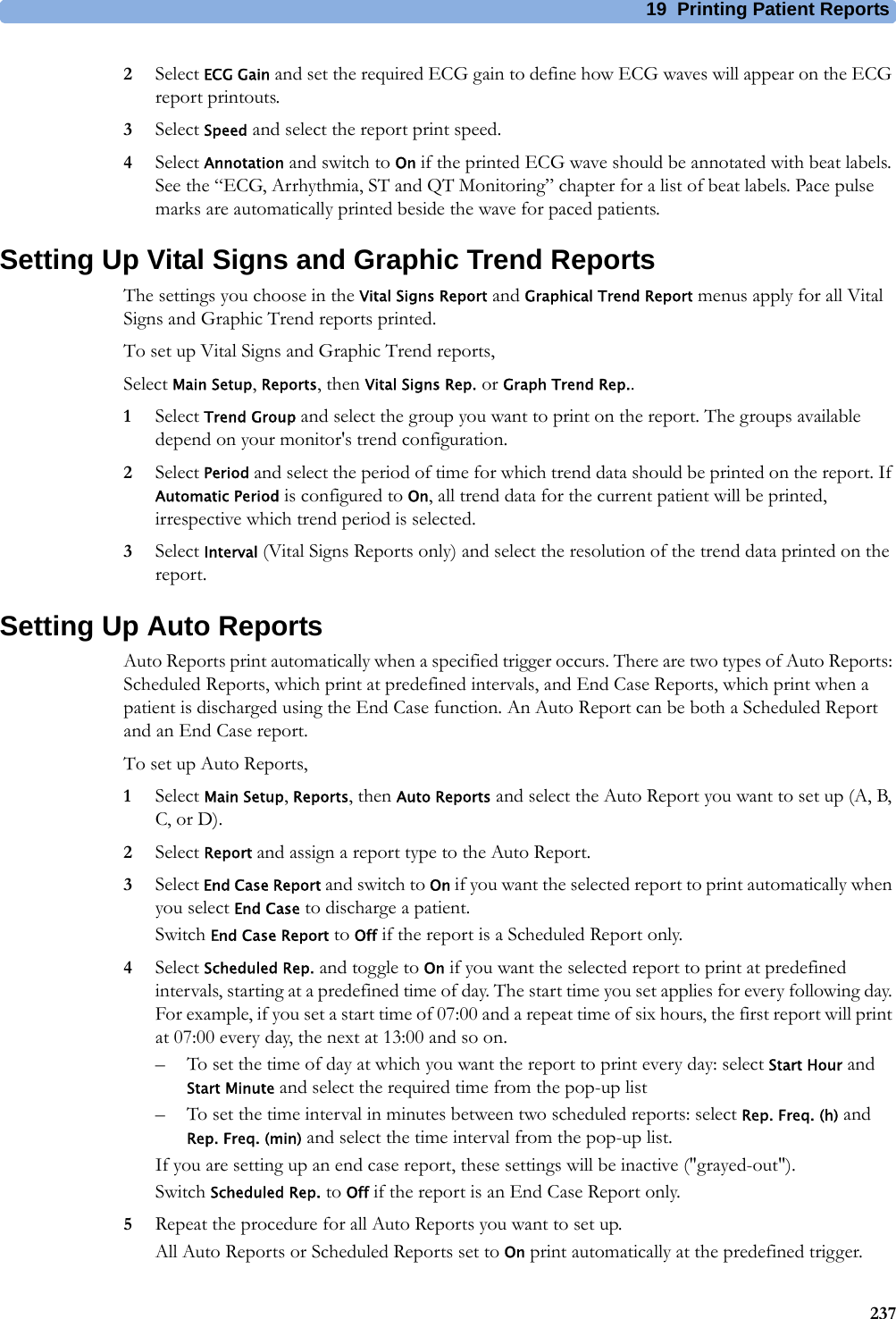
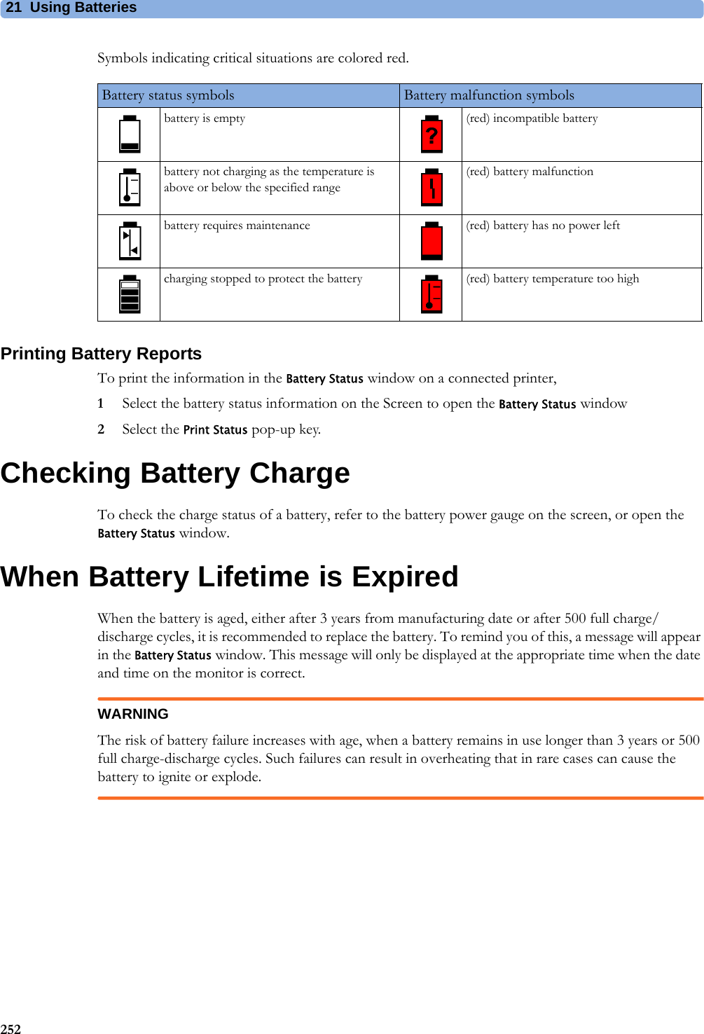
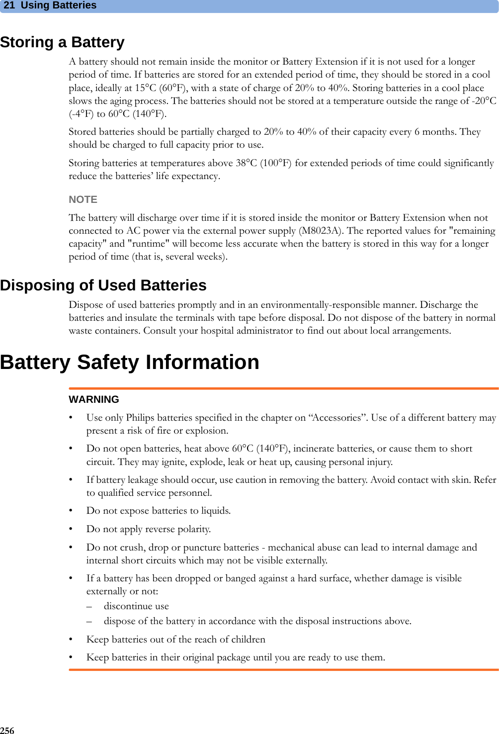
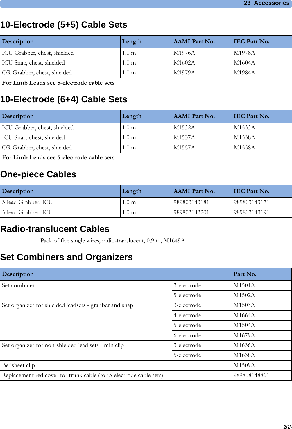
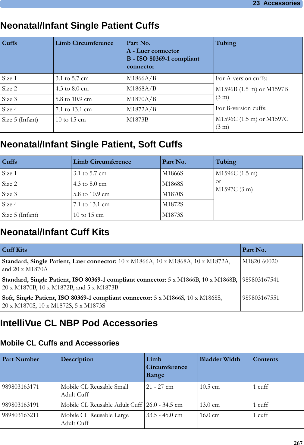
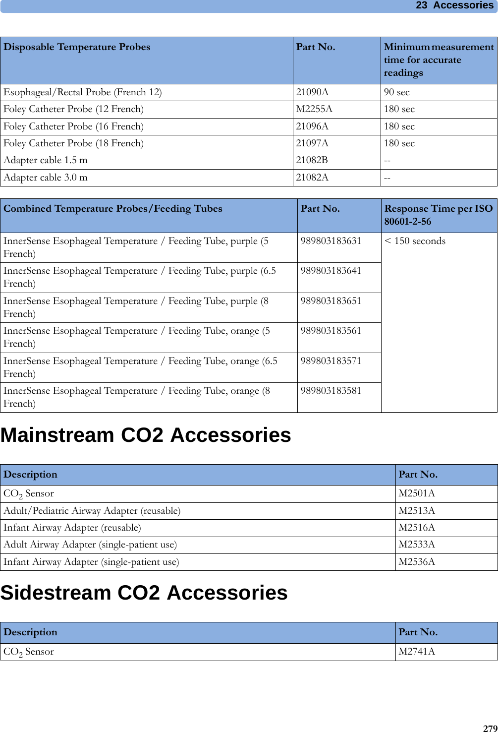
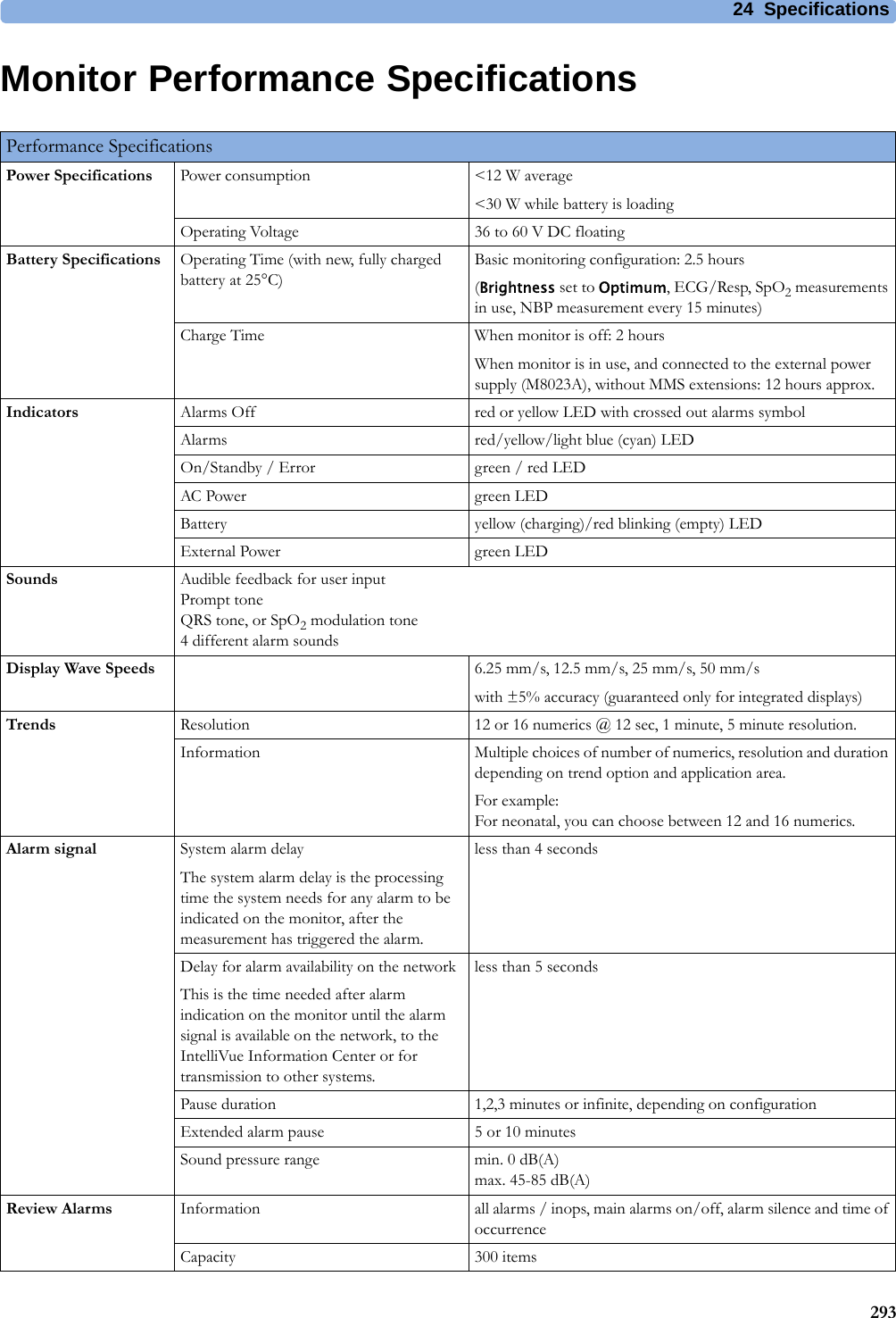
![4 Patient Alarms and INOPs74Resp INOPsNBP INOPsSome ECG AlarmsOff This message appears (if configured to do so) when the on/off settings of the yellow arrhythmia alarms differ from the current Profile.INOP Message, Indication What to do INOP Message, Indication What to do Resp Equip MalfNumeric is replaced by -?-INOP toneContact your service personnel. The RESP hardware is faulty.Resp ErraticNumeric is replaced by -?-The monitor has detected too many artifacts in the measured Resp signal. Check that the RA and LL electrodes are correctly attached and have not dried out.Resp Leads OffNumeric is replaced by -?-INOP toneNot all the required leads for Resp monitoring are attached. Make sure that the RA, LA, and LL leads are attached.INOP Message, Indication What to do !! Cuff Not Deflat!!!Cuff Not DeflatNumeric is displayed with a -?-Severe yellow/red INOP toneDuring this INOP, alarms cannot be paused or switched off.Remove the cuff from the patient. Make sure that the tubing is not kinked or twisted and that the correct patient category is selected. Try repeating the measurement. You can silence the INOP, but the INOP message remains visible until the next NBP measurement is started or the Stop All SmartKey is selected.[Adult or pediatric patients: The NBP cuff pressure has exceeded 15 mmHg (2 kPa) for more than 3minutes. Neonatal patients: The NBP cuff pressure has exceeded 5 mmHg (0.7 kPa) for more than 90 seconds.]!! Cuff Overpress!!!Cuff OverpressNumeric is displayed with a -?-Severe yellow/red INOP toneDuring this INOP, alarms cannot be paused or switched off.The NBP cuff pressure exceeds the overpressure safety limits. Remove the cuff from the patient. Make sure that the tubing is not kinked or twisted and that the correct patient category is selected. Try restarting the measurement. You can silence this INOP, but the INOP message remains visible until the next measurement is started or the Stop All SmartKey is selected.NBP DeactivatedINOP toneThe NBP measurement label in the measurement device has been deactivated by deactivating the label in the Measurement Selection window. The measurement automatically disappears from the display. To switch the measurement on again, reactivate the measurement label in the Measurement Selection window.NBP Equip MalfNumeric is replaced by -?-INOP toneRemove the cuff from the patient. The NBP hardware is faulty. Contact your service personnel. You can silence this INOP, but the INOP message remains visible until the next measurement is started or the Stop All SmartKey is selected.NBP InterruptedNumeric is replaced by -?-INOP toneCheck the tubing and cuff for leakages or kinks. Check that you are using the correct cuff size and placement, and that the correct patient category is selected. Try restarting the measurement. If the INOP occurs repeatedly, contact your service personnel.You can silence this INOP, but the INOP message remains visible until the next measurement is started or the Stop All SmartKey is selected.This INOP arises when the measurement needed longer than the maximum time for inflation, deflation or the total measurement.NBP Measure FailedNumeric may be replaced by -?-INOP toneCheck that you are using the correct cuff size and placement, and that the correct patient category is selected. Try restarting the measurement.You can silence this INOP, but the INOP message remains visible until the next measurement is started or the Stop All SmartKey is selected.Check the condition and suitability of the patient for NBP monitoring. Use another cuff to continue measuring.](https://usermanual.wiki/Philips-Medical-Systems-North-America/WLANBV3.user-manual-mp2-english/User-Guide-3422182-Page-74.png)
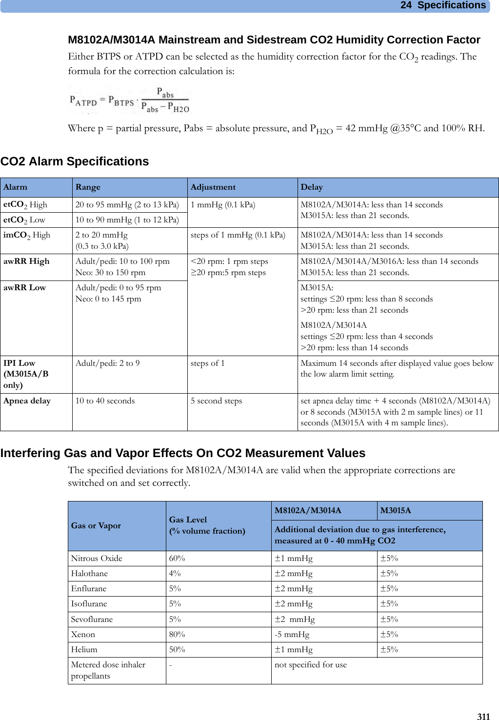
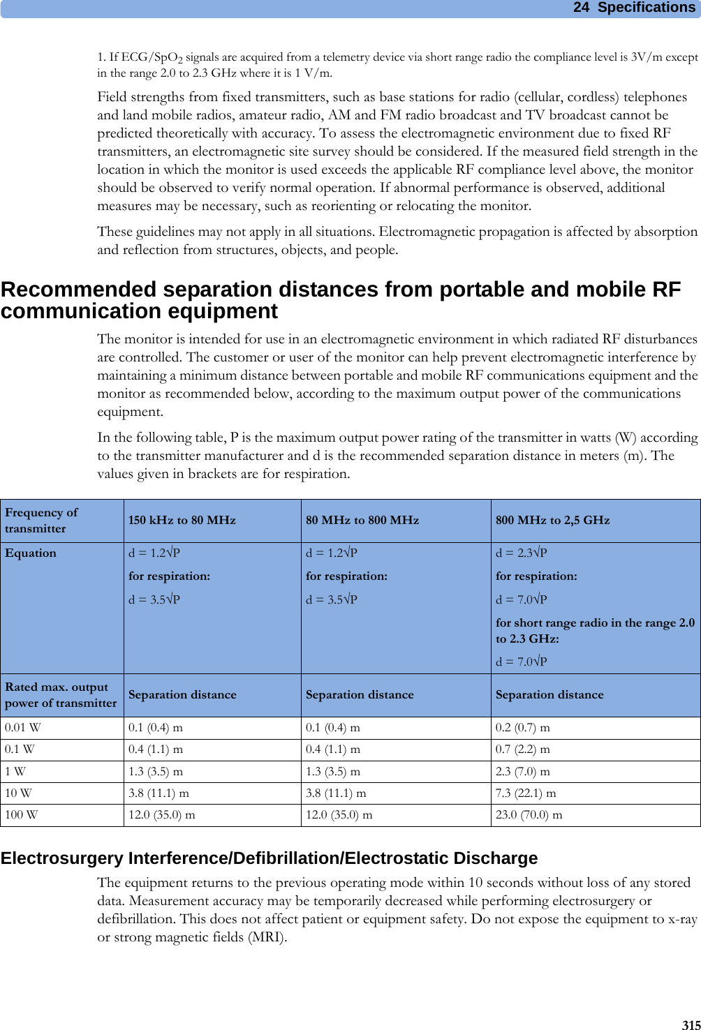
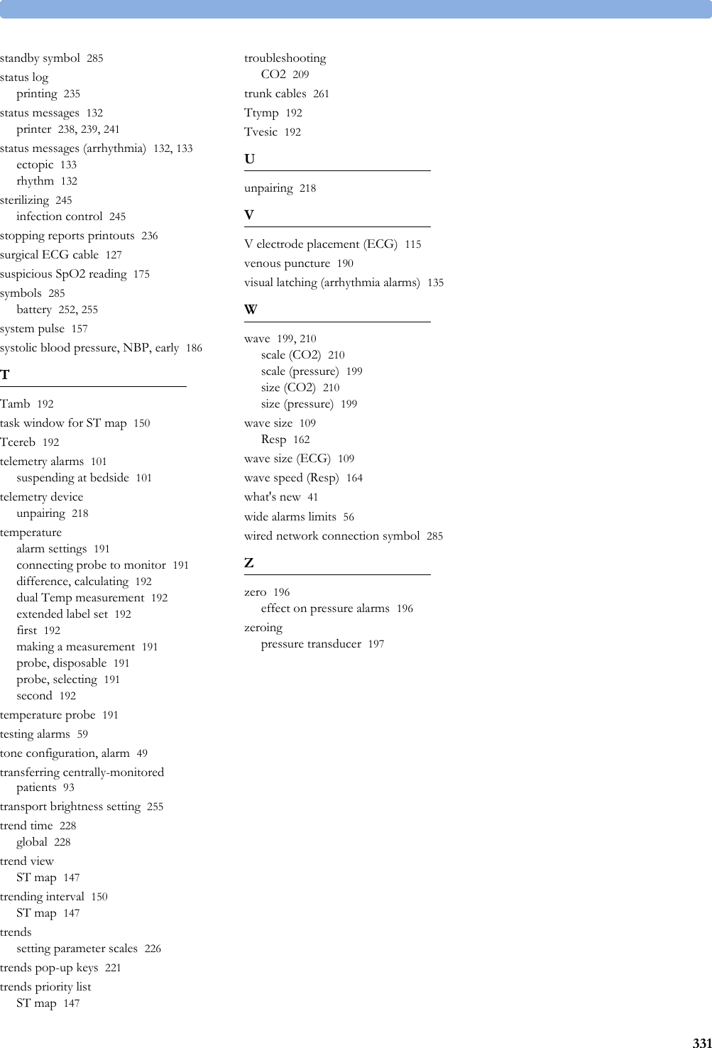
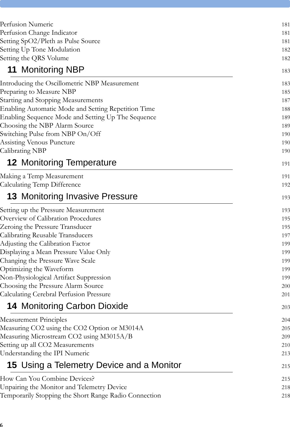
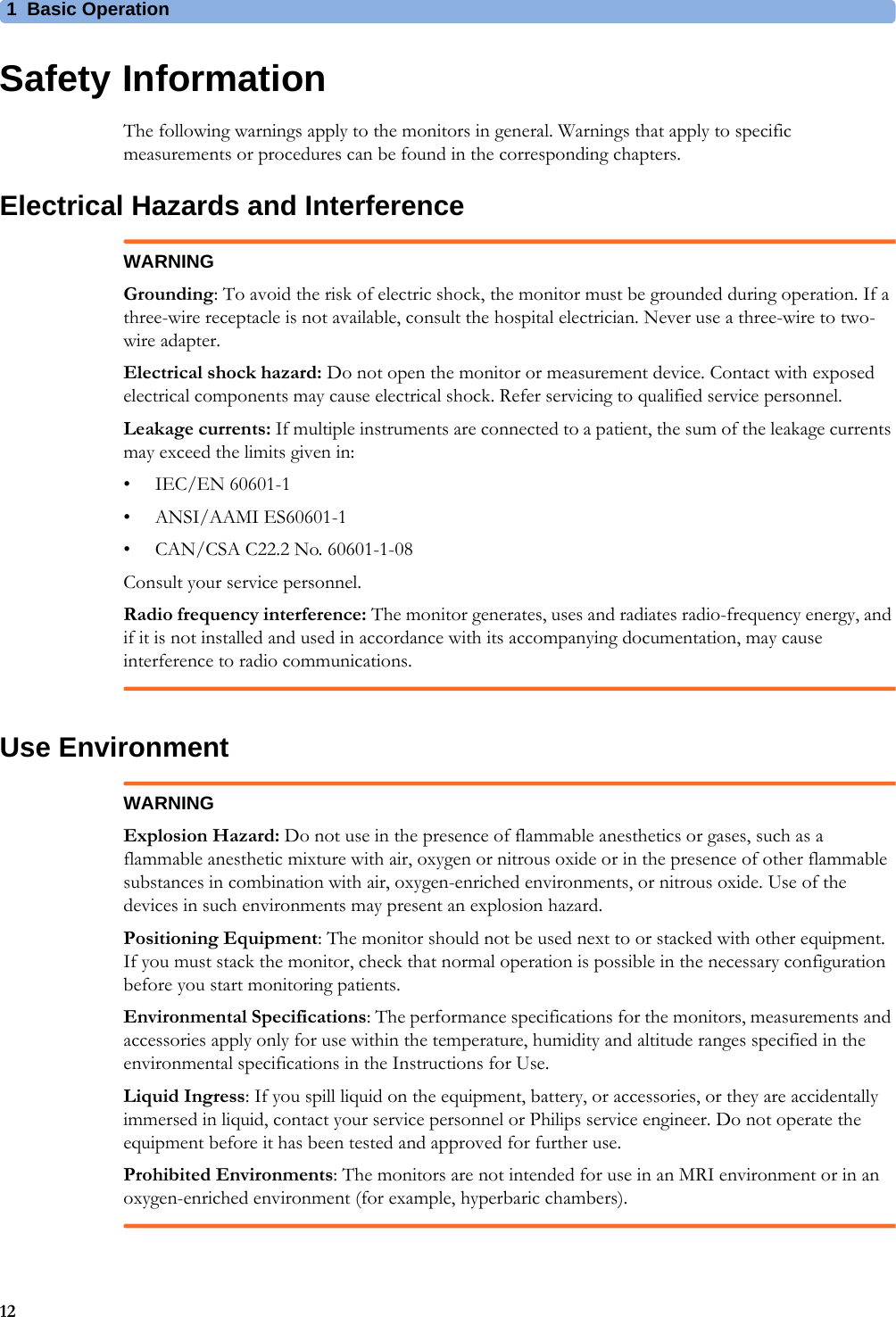
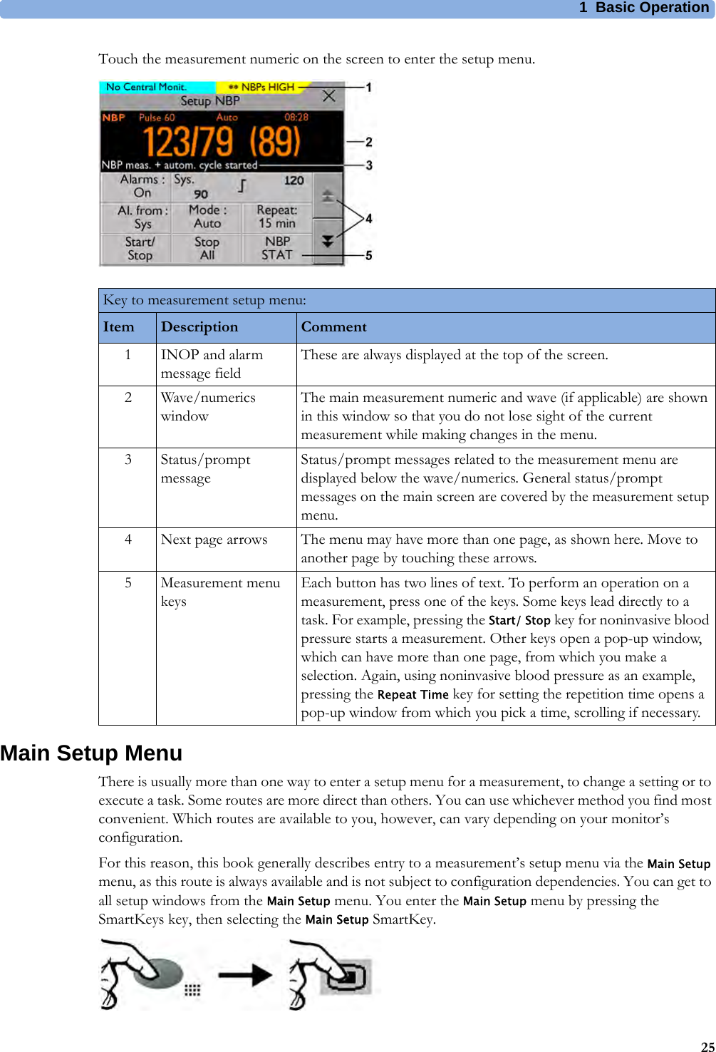
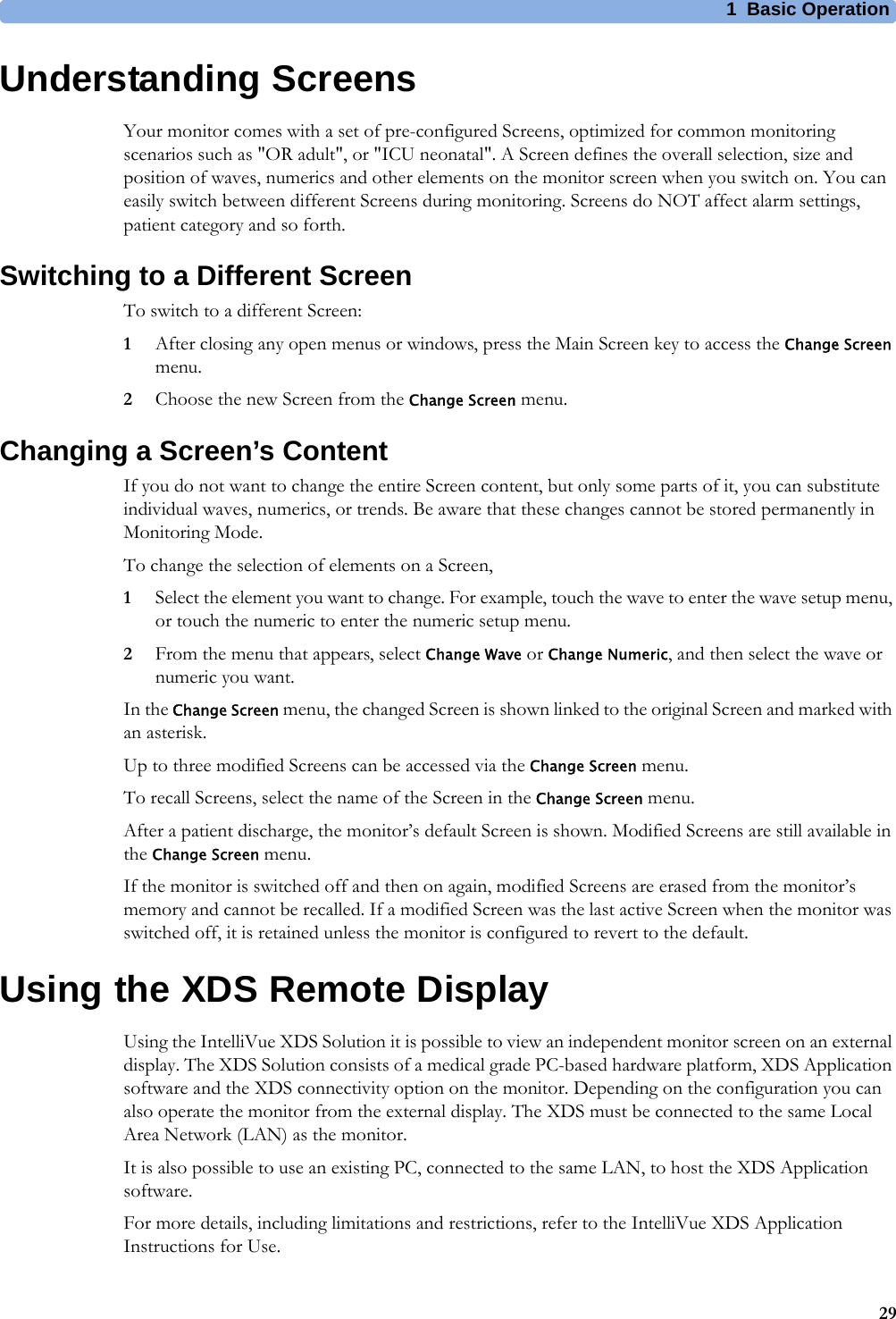
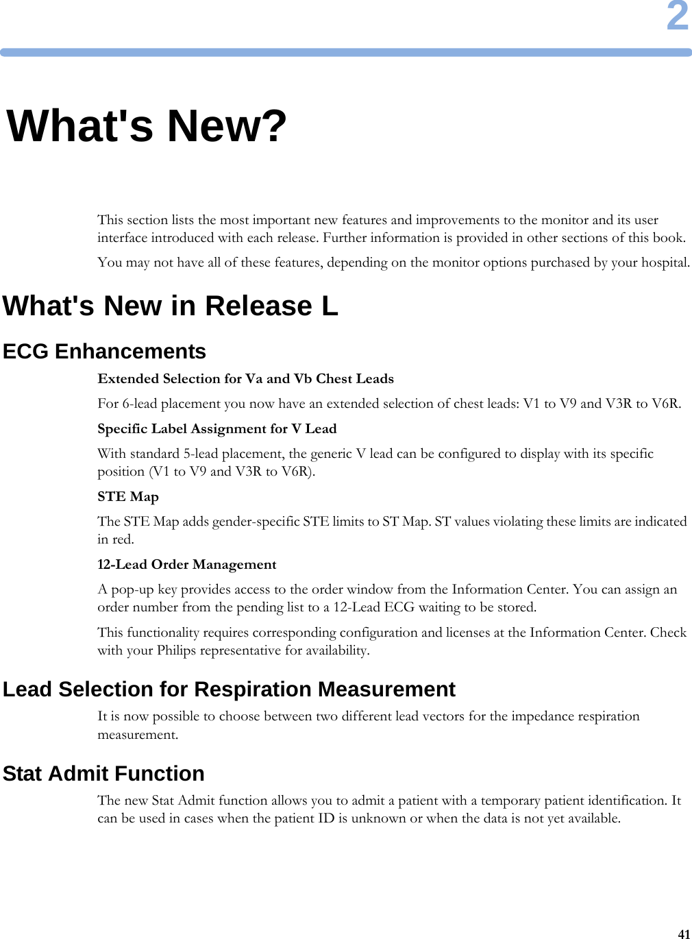
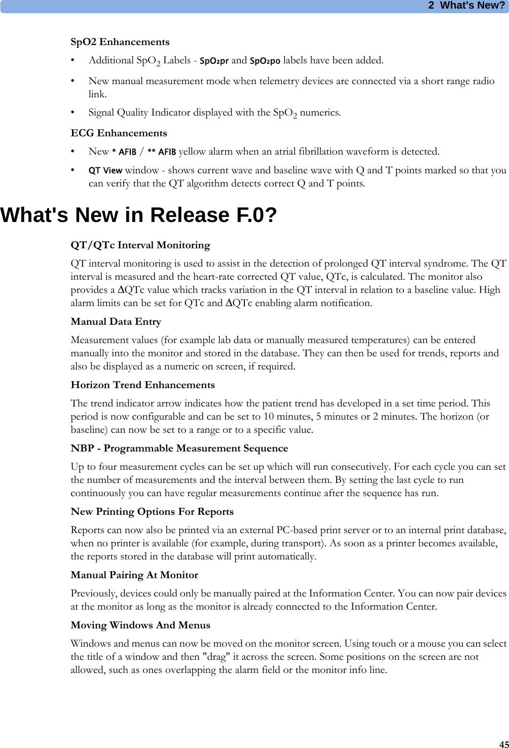
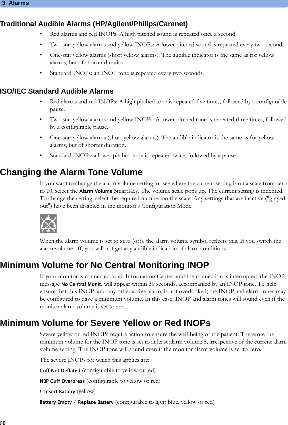
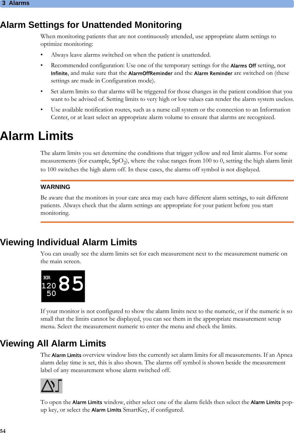
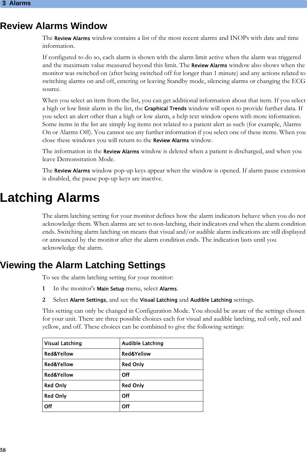
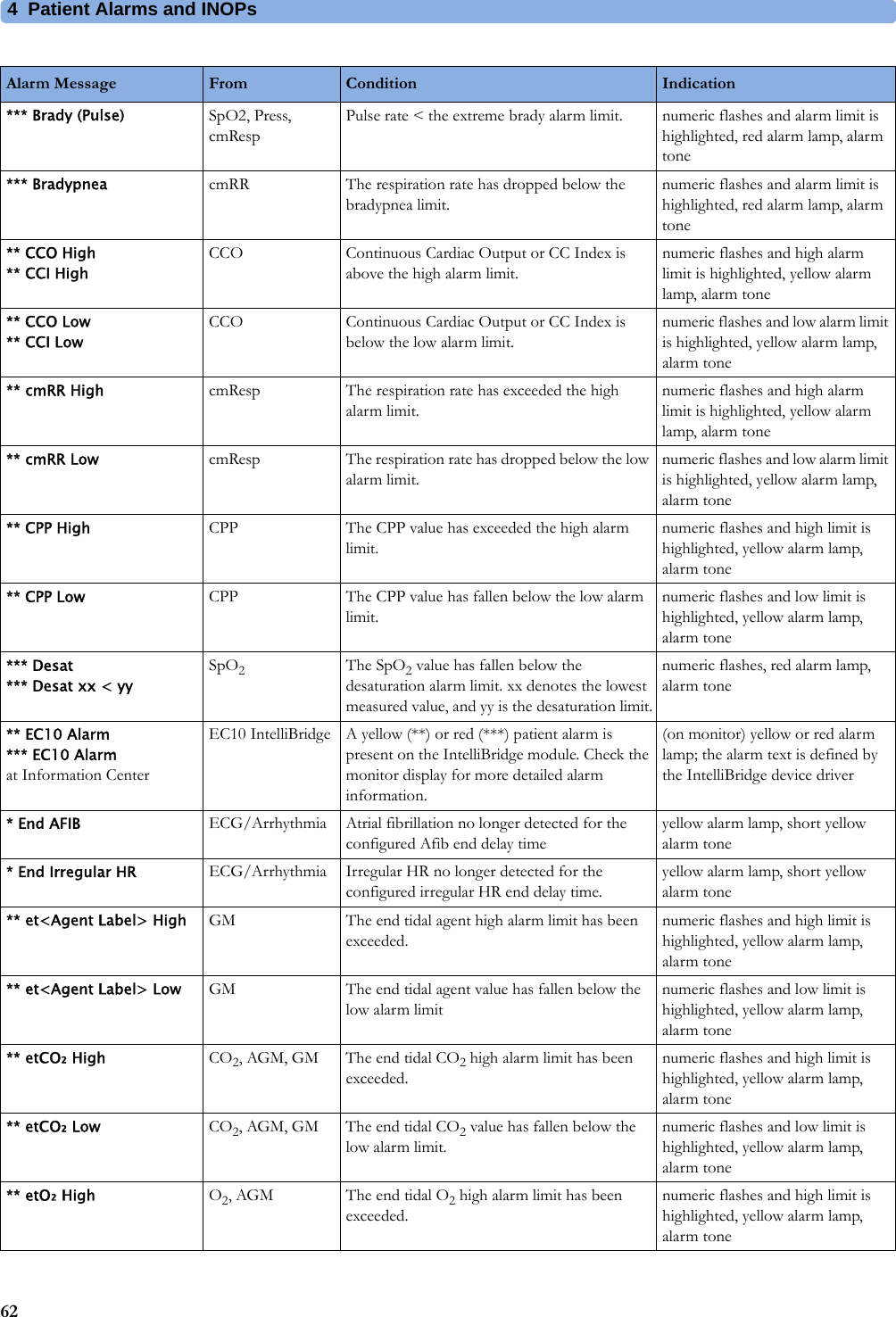
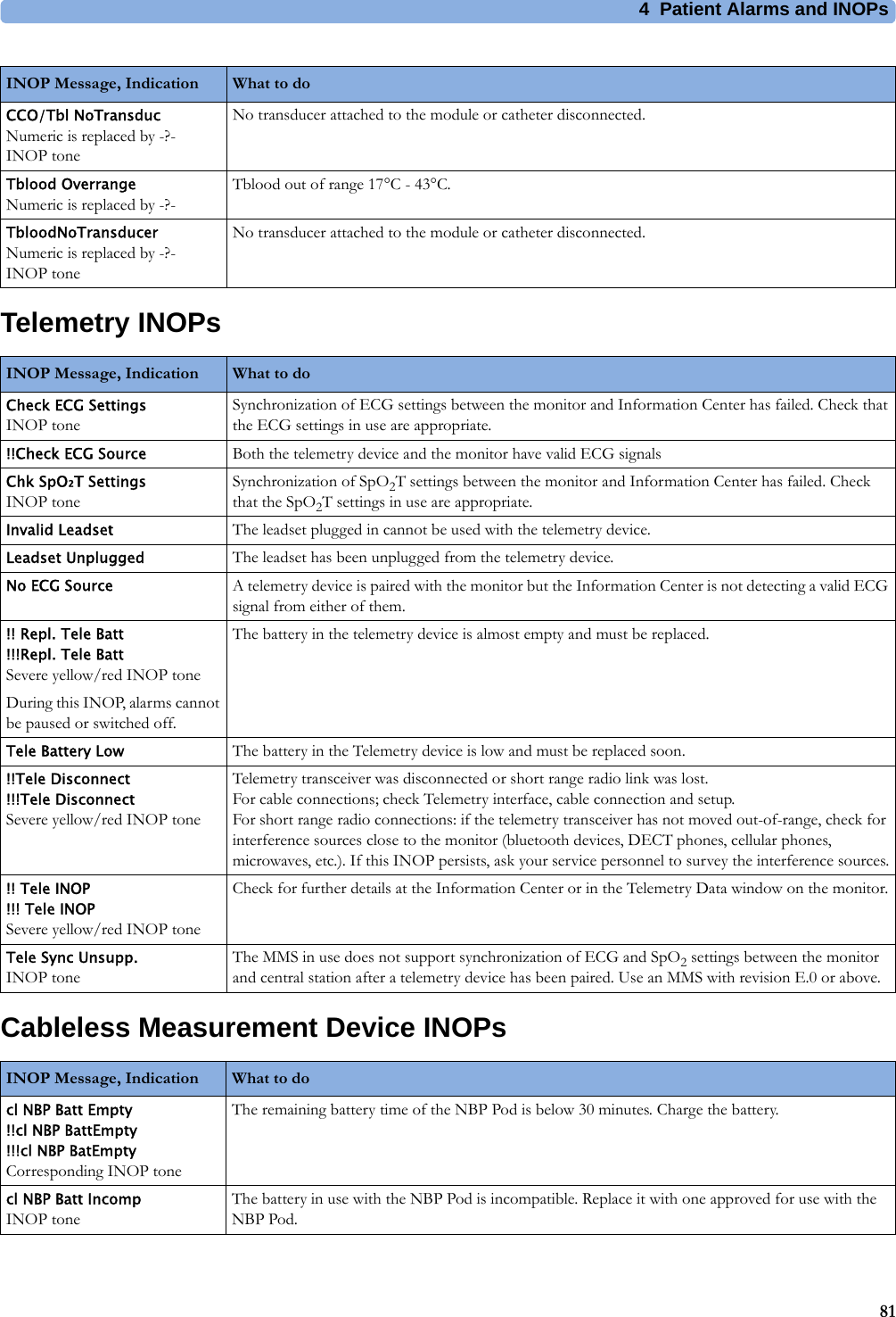
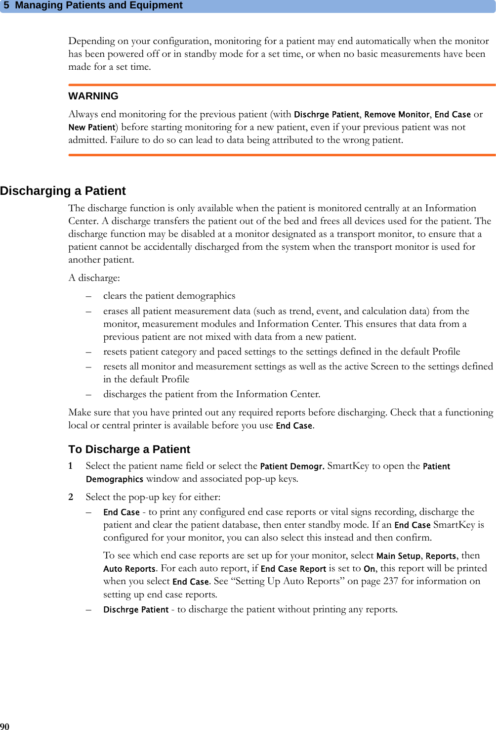
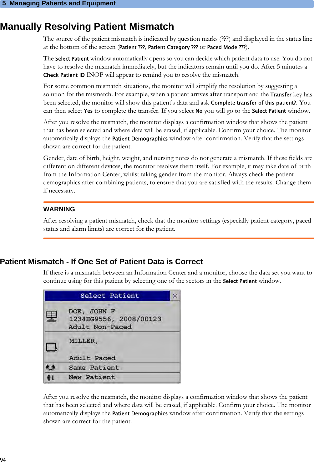
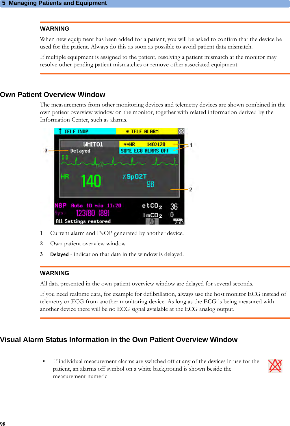
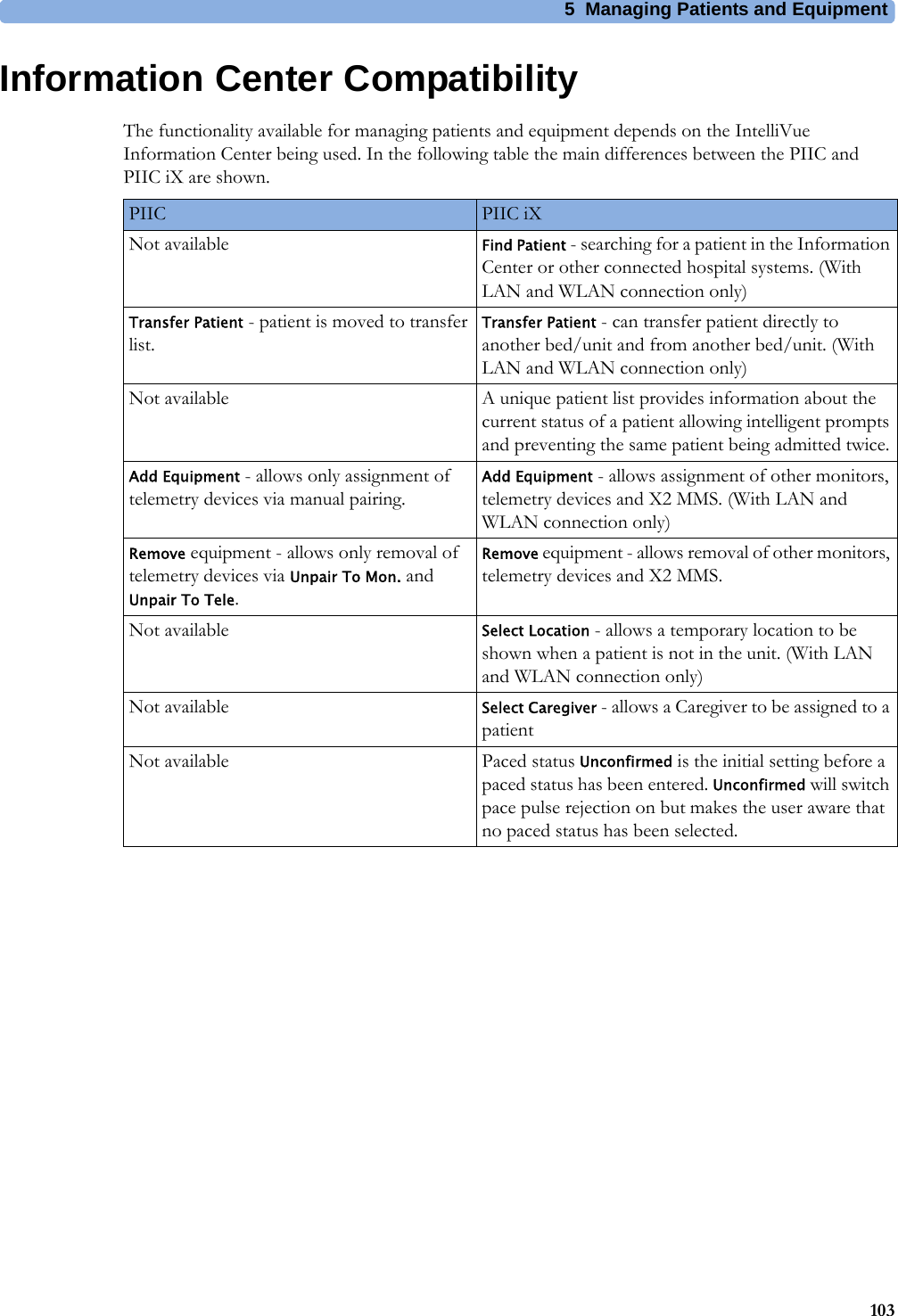
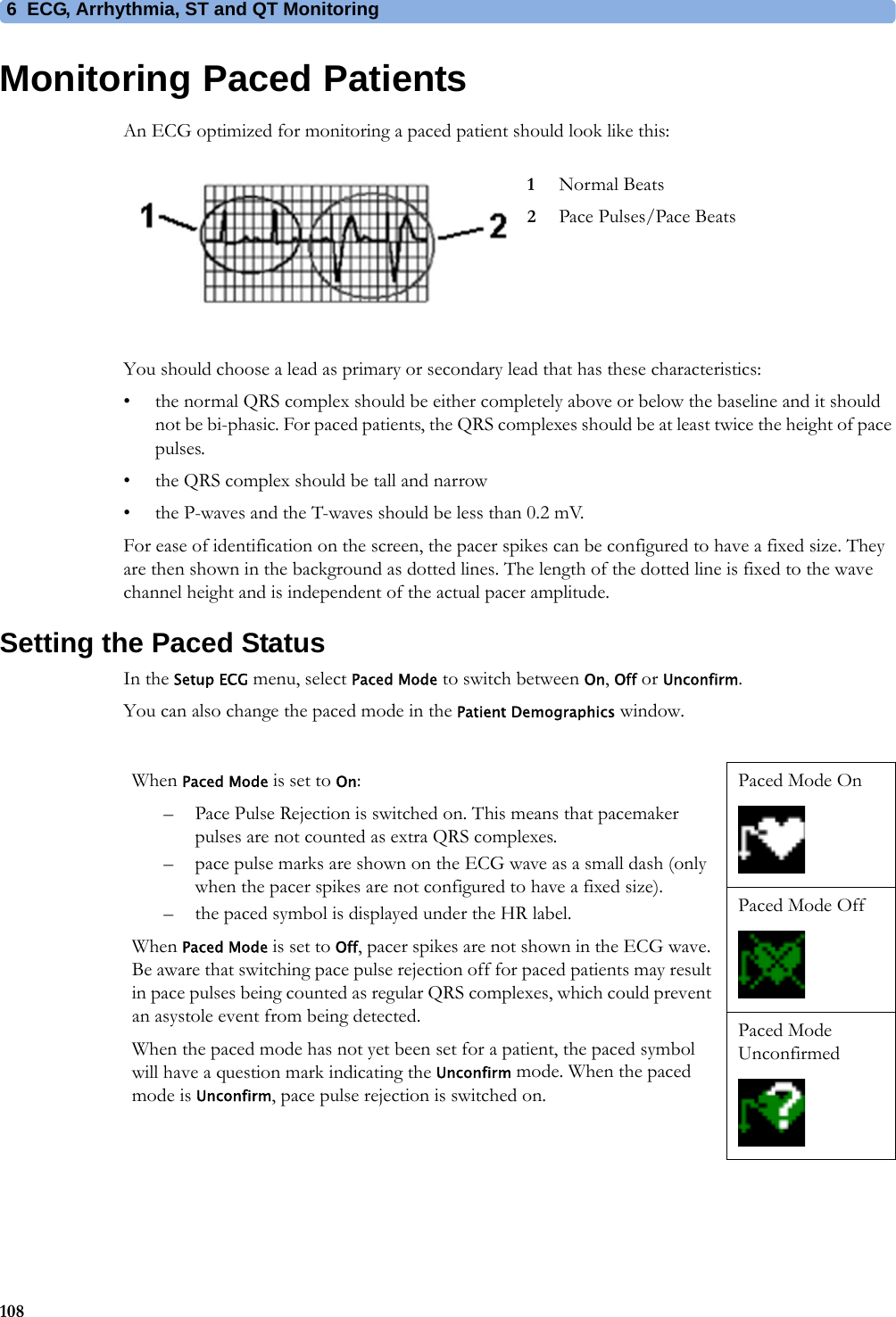
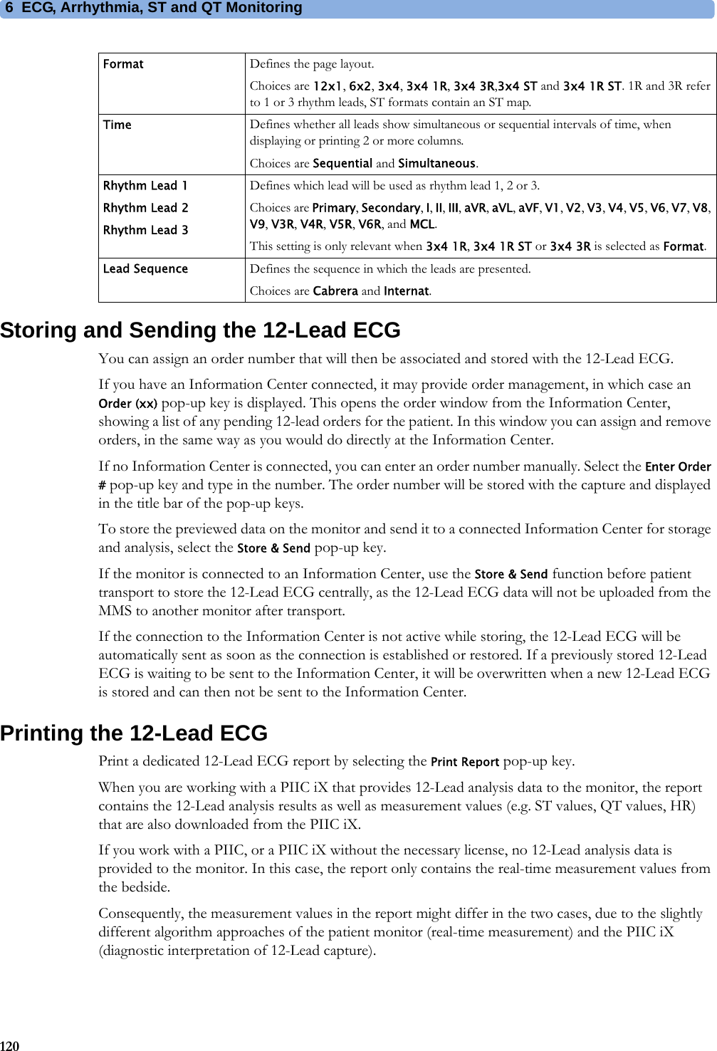
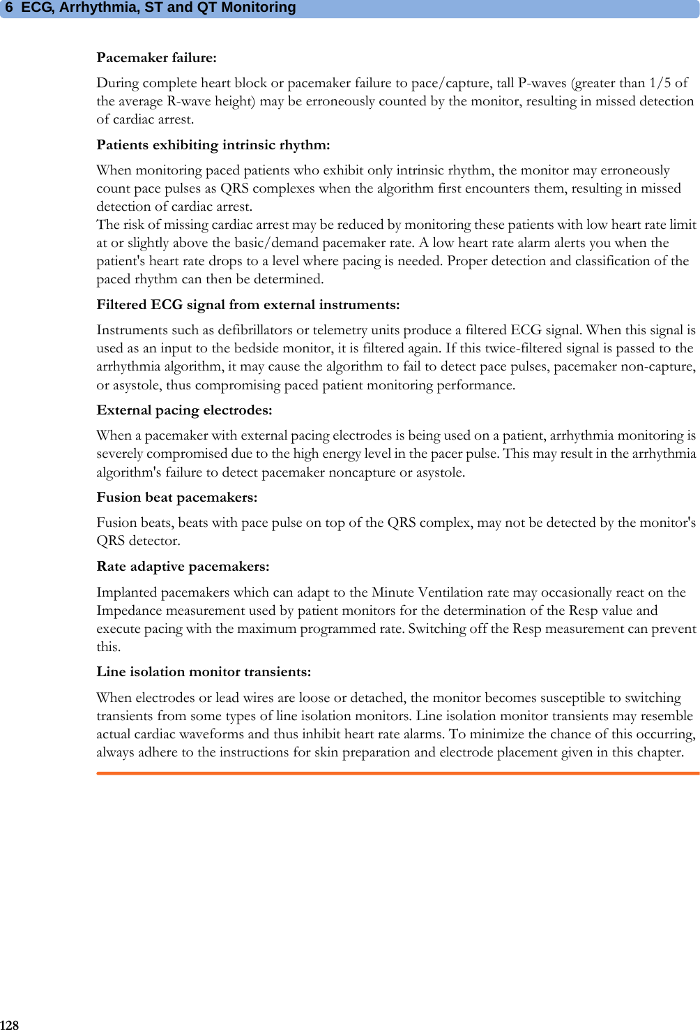
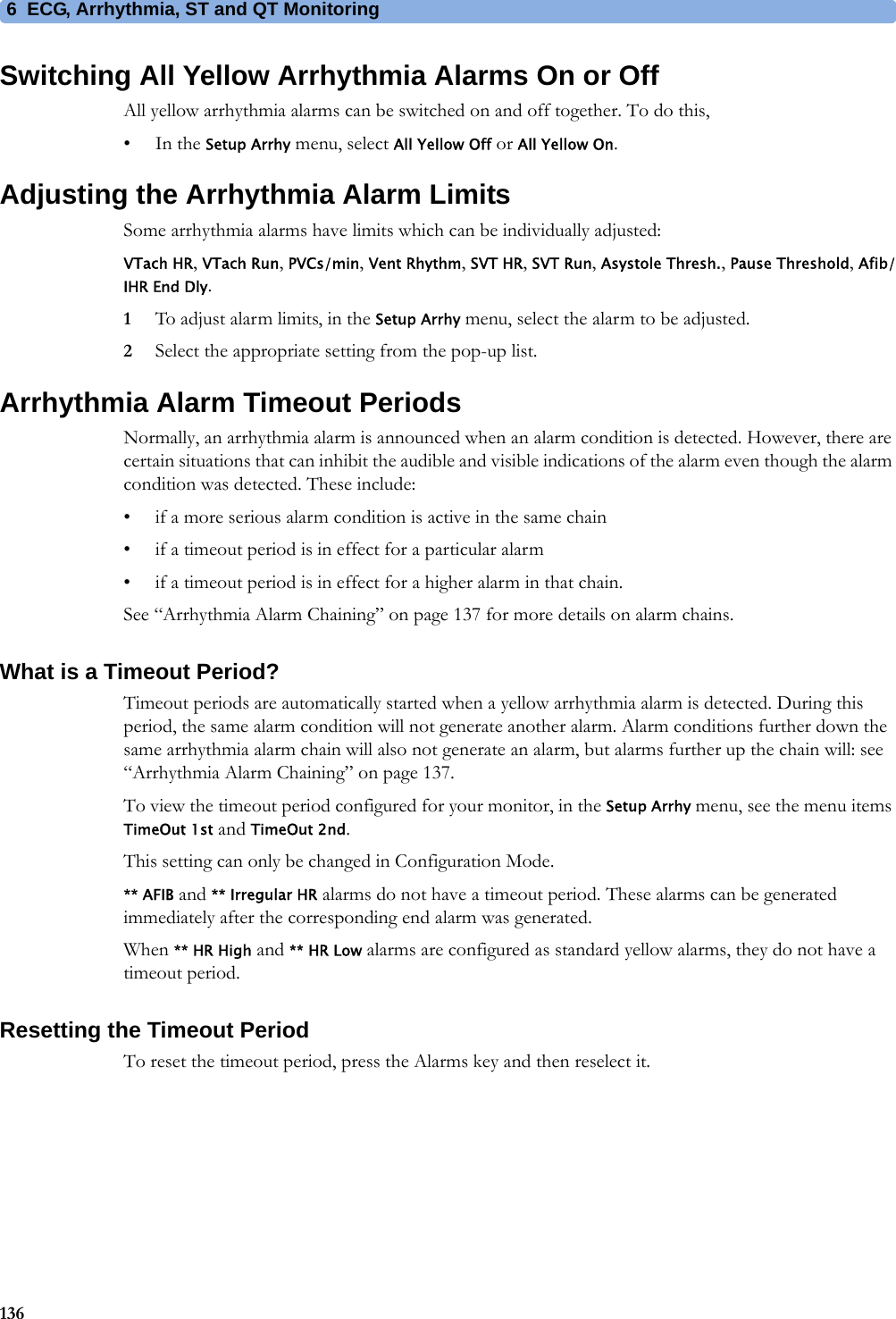
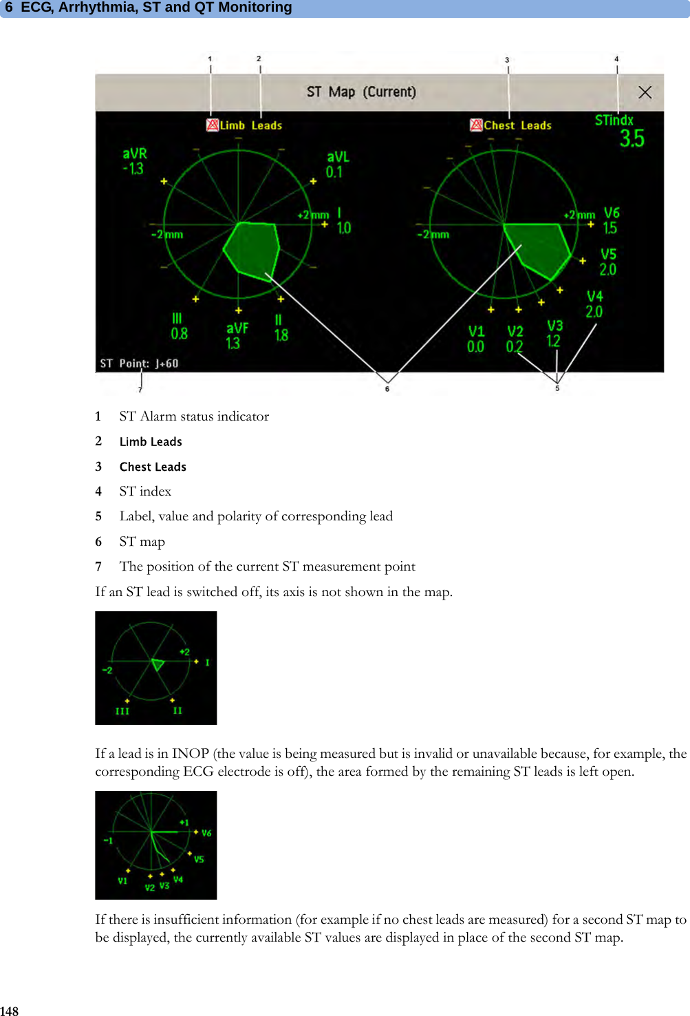
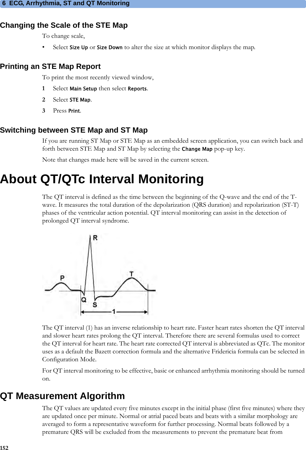
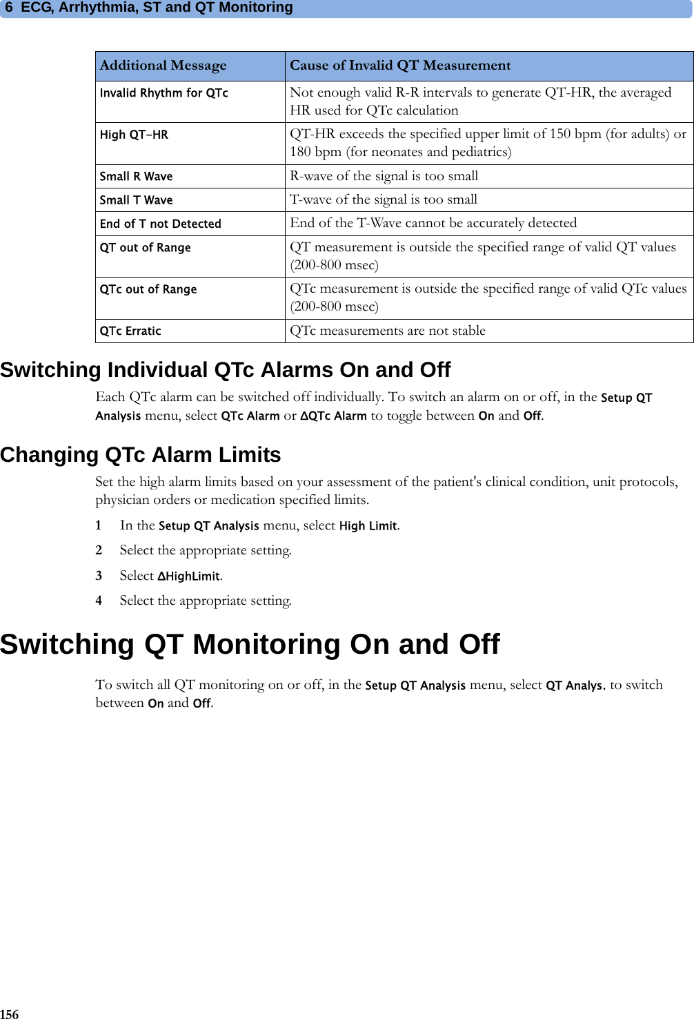
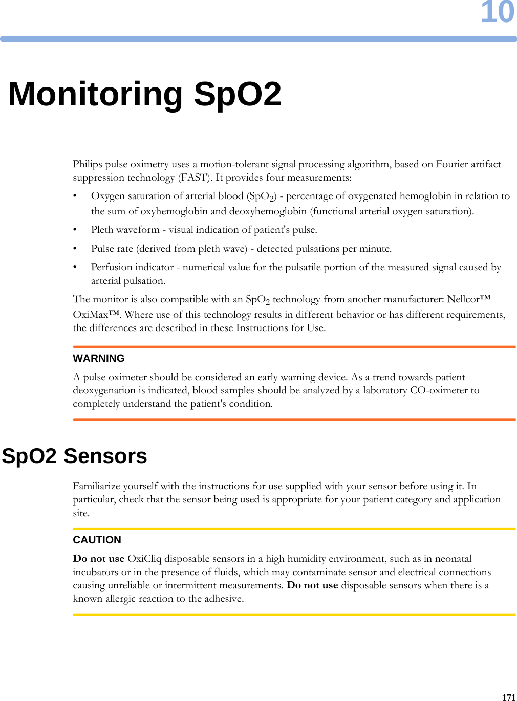
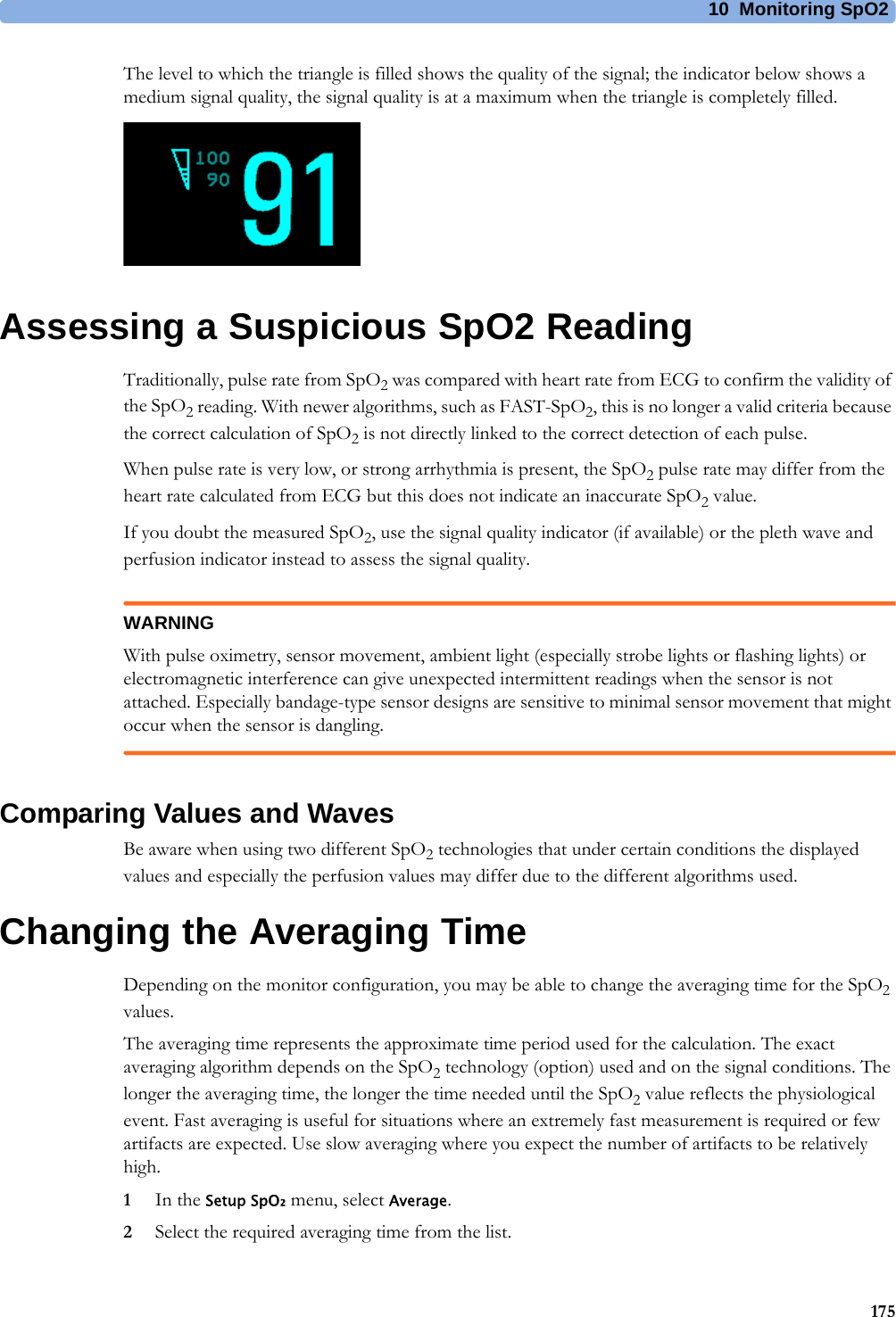
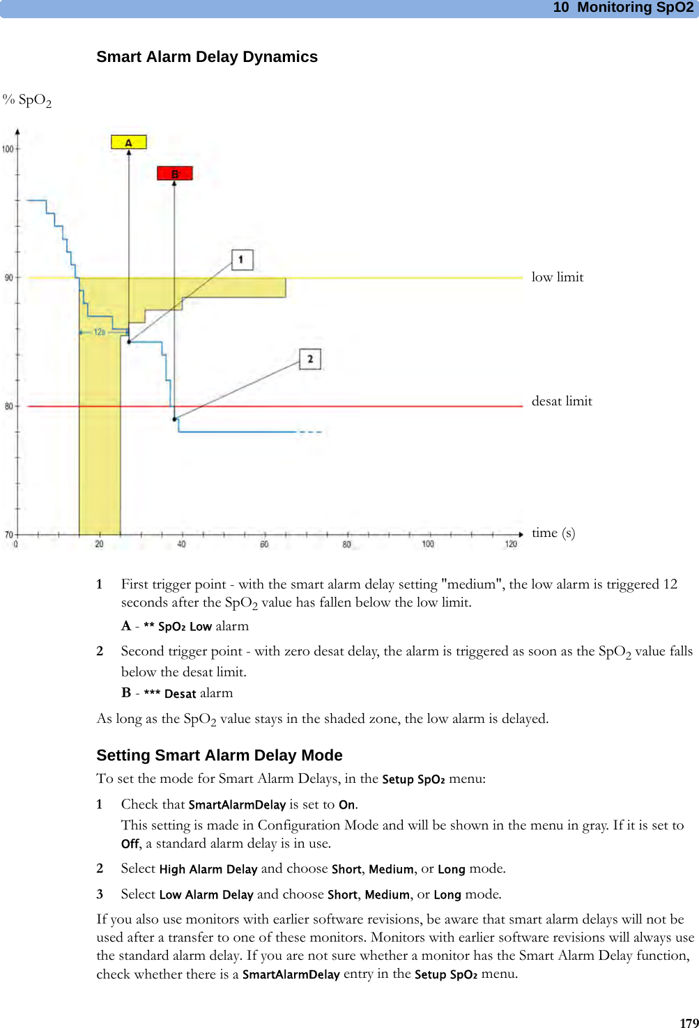
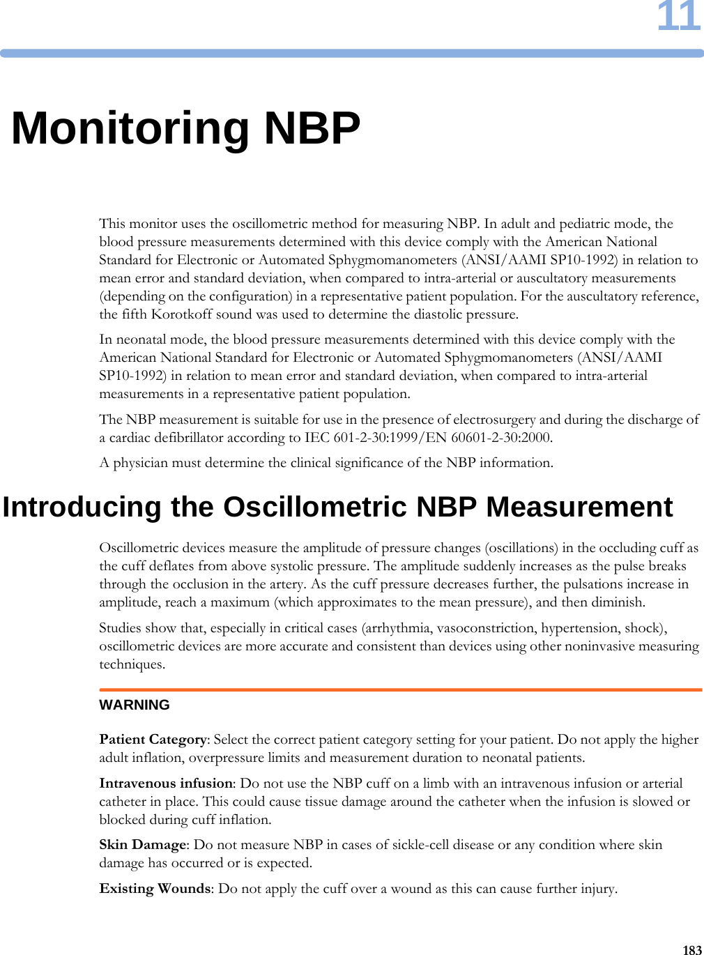
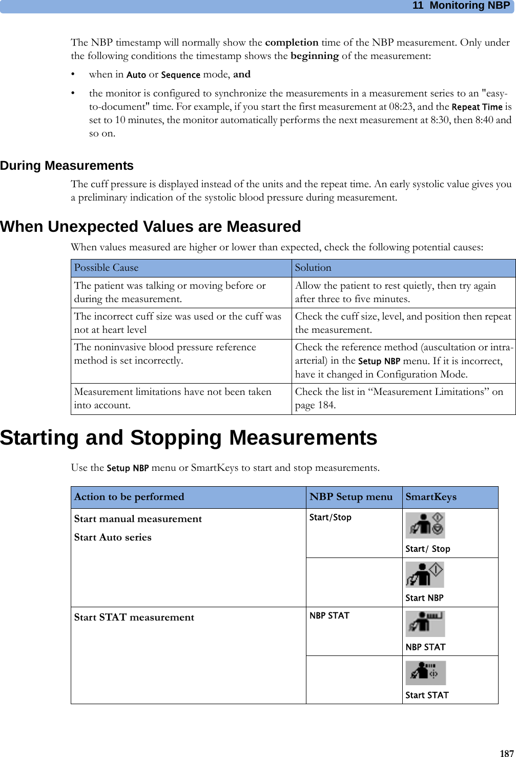
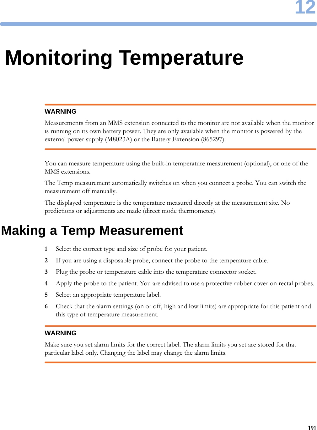
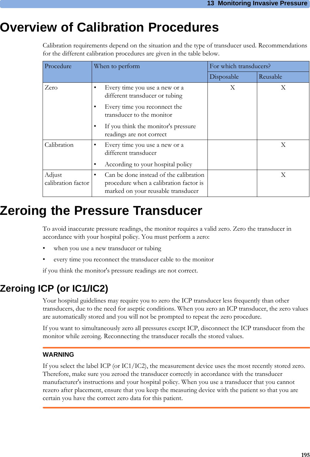
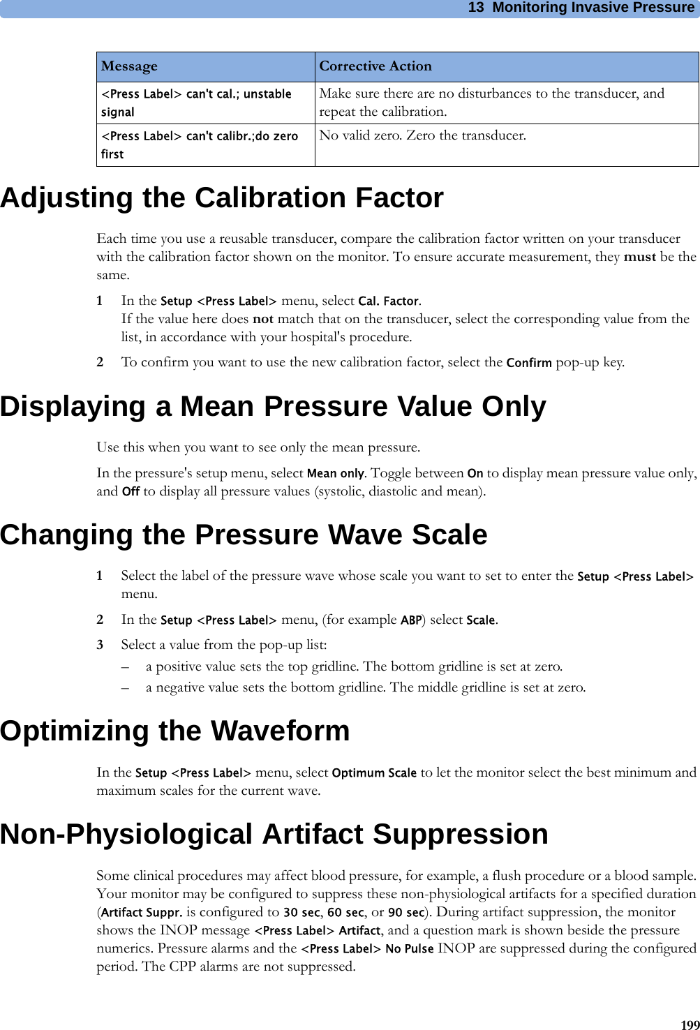
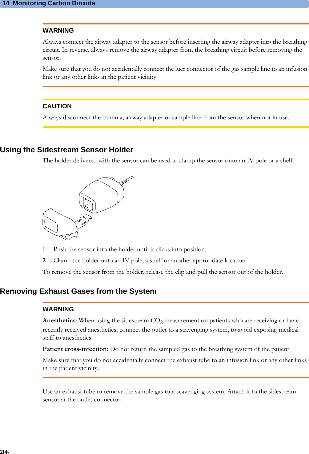
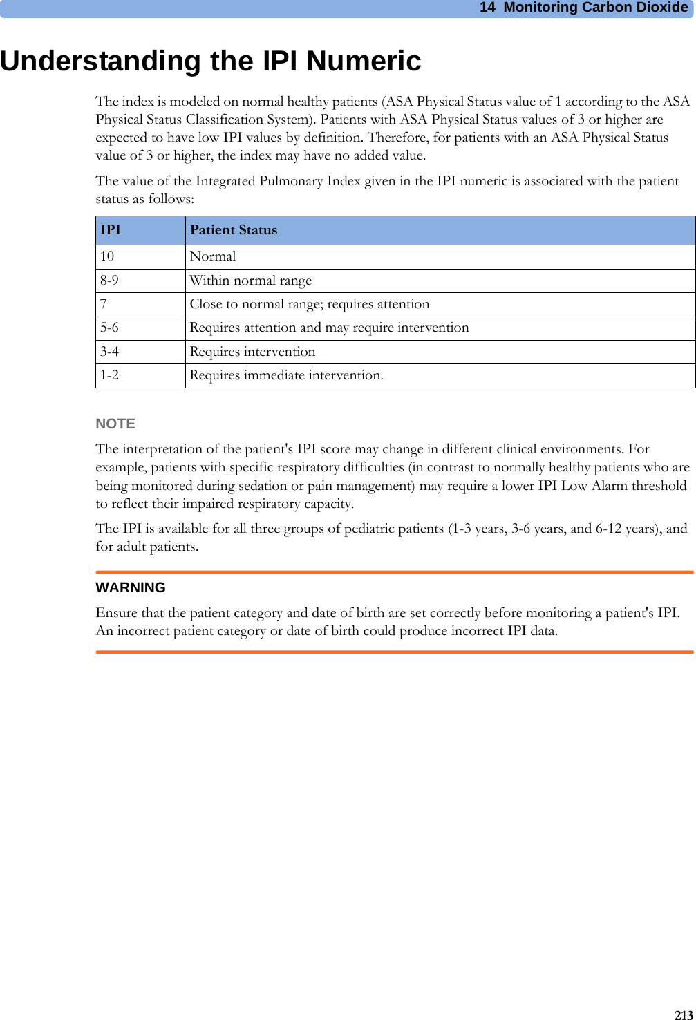
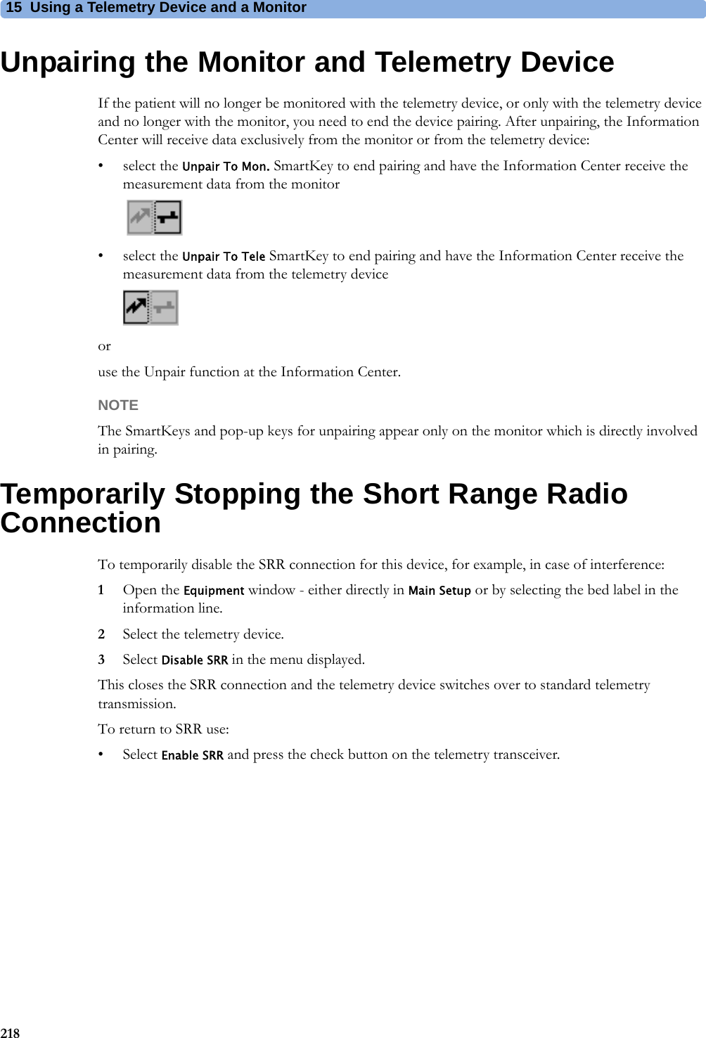
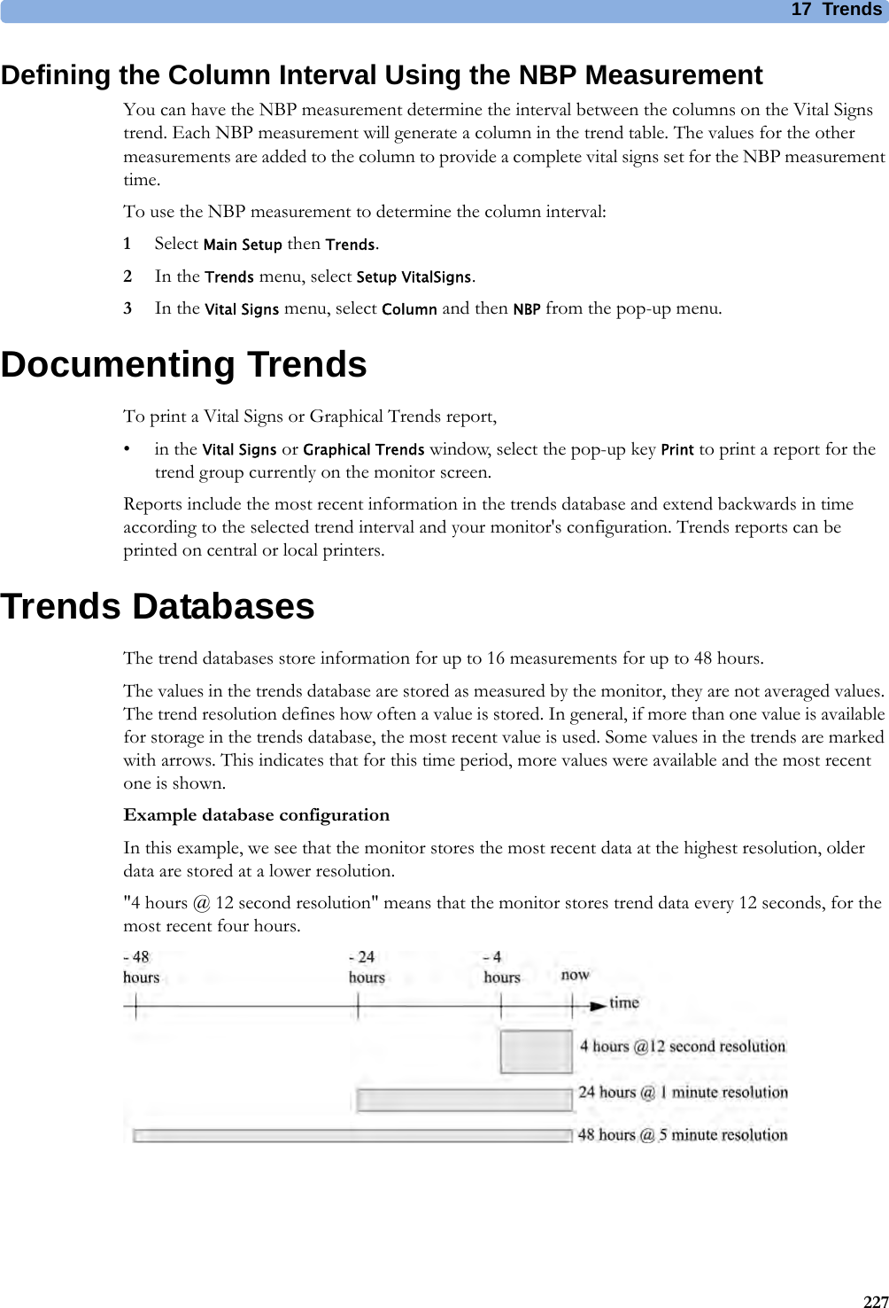
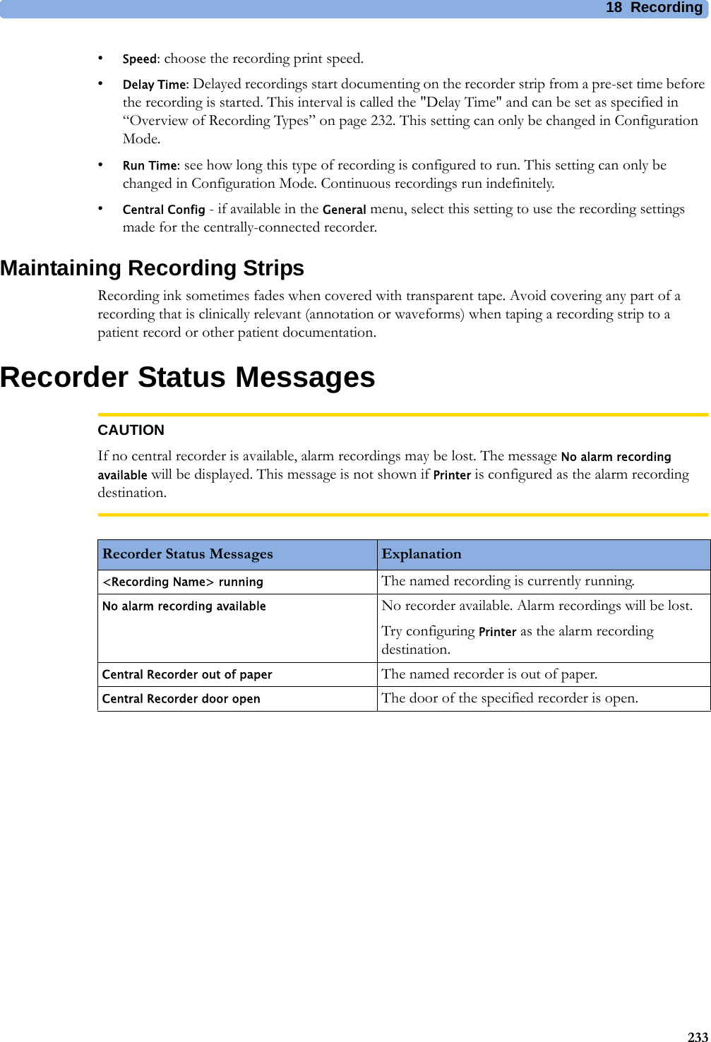
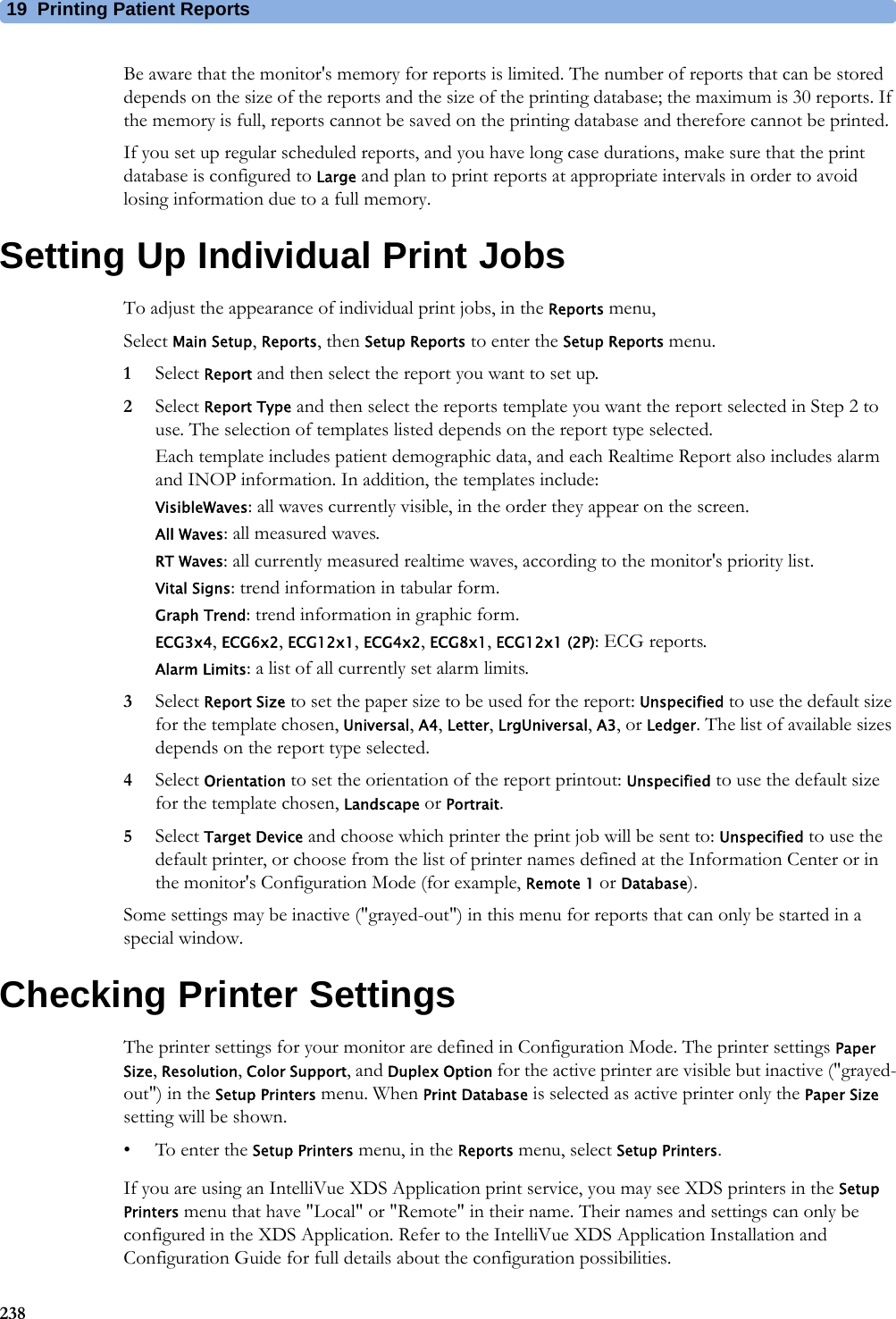
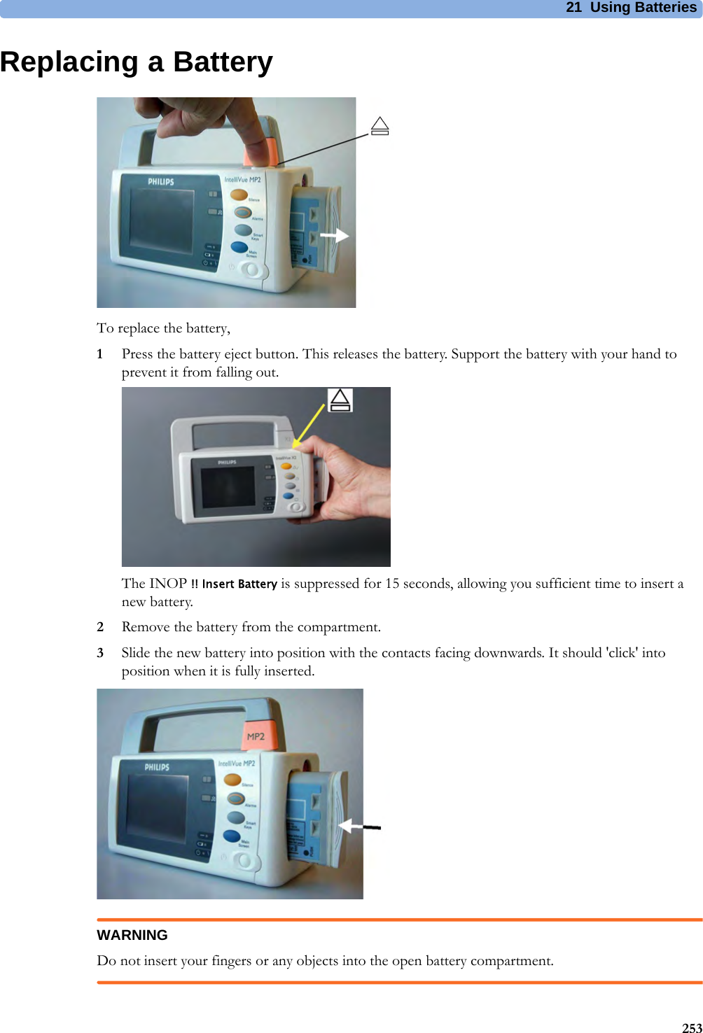
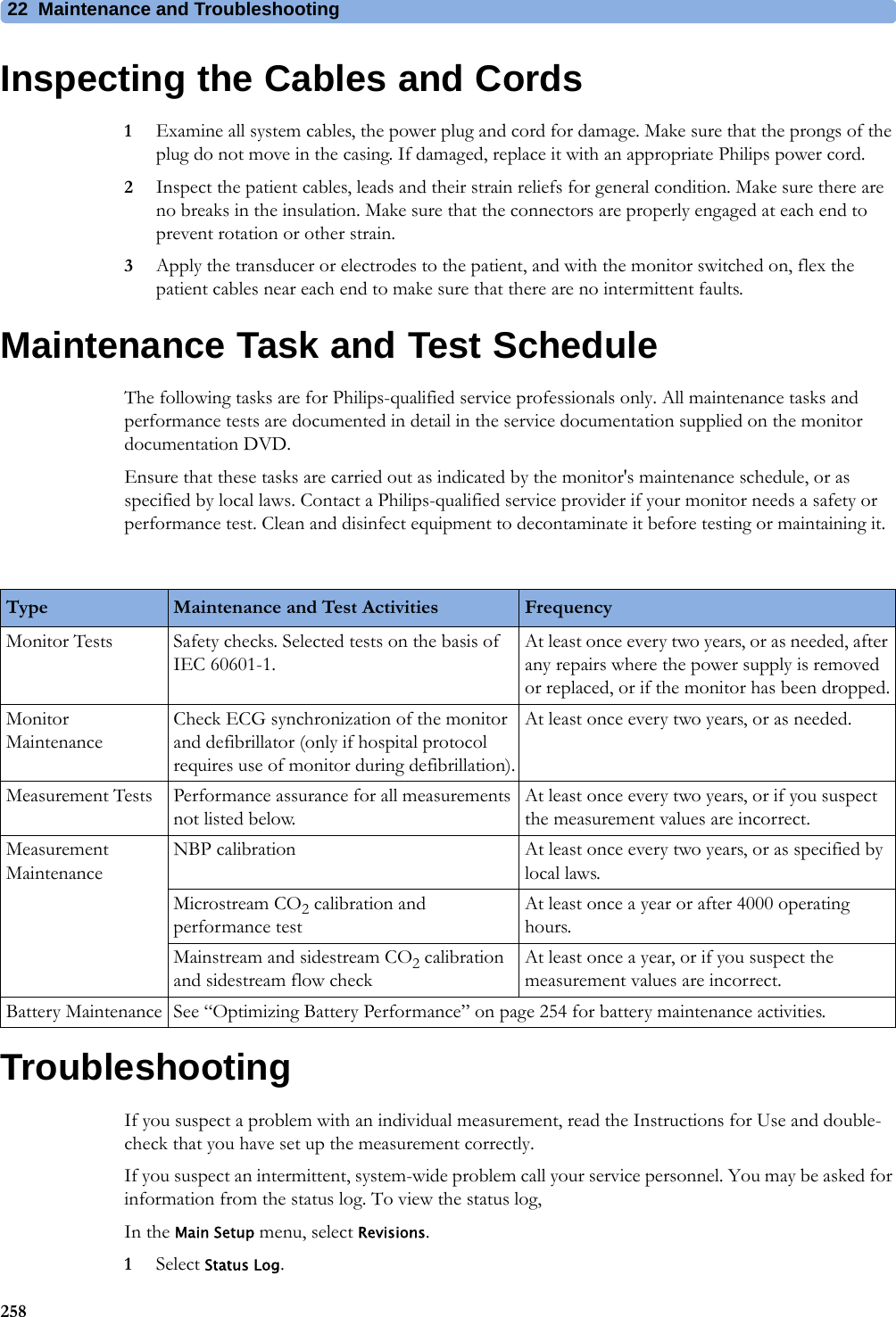
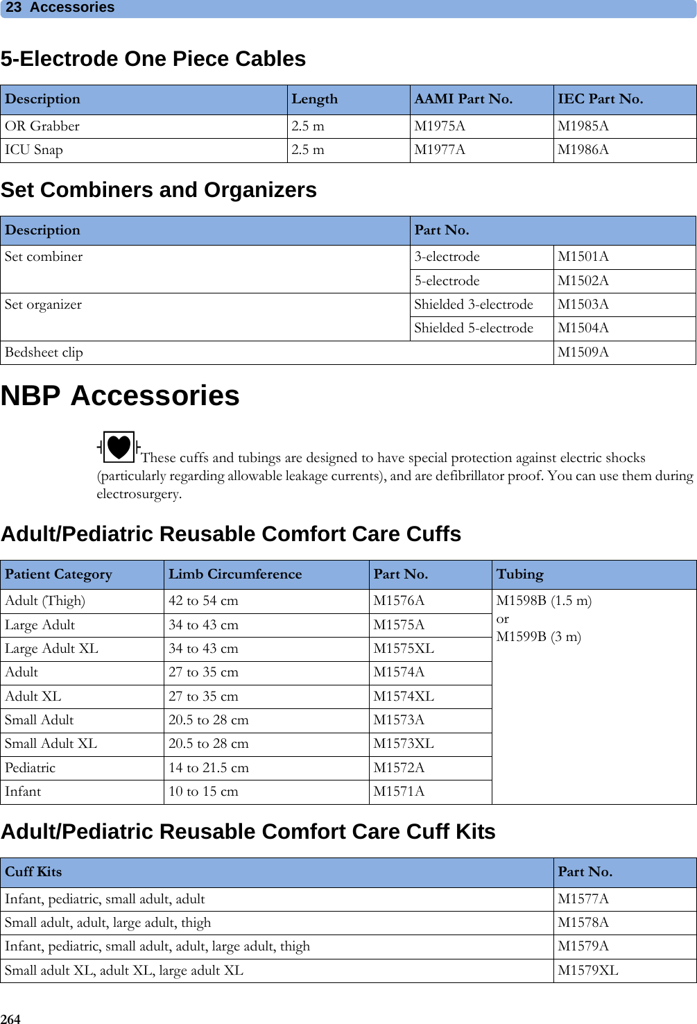
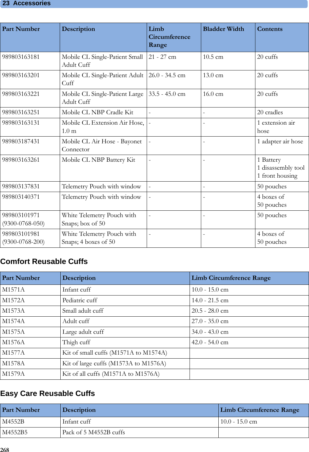
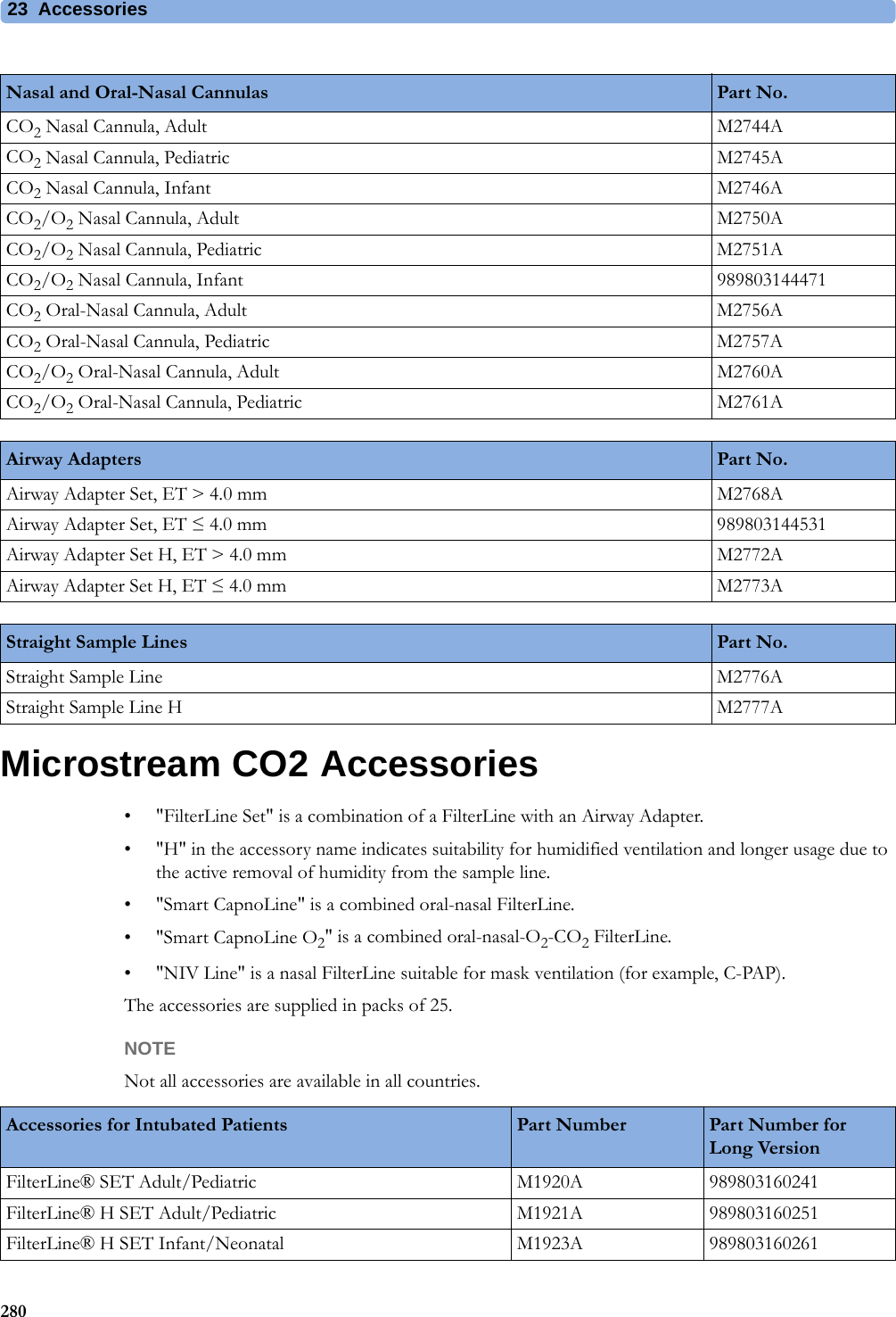
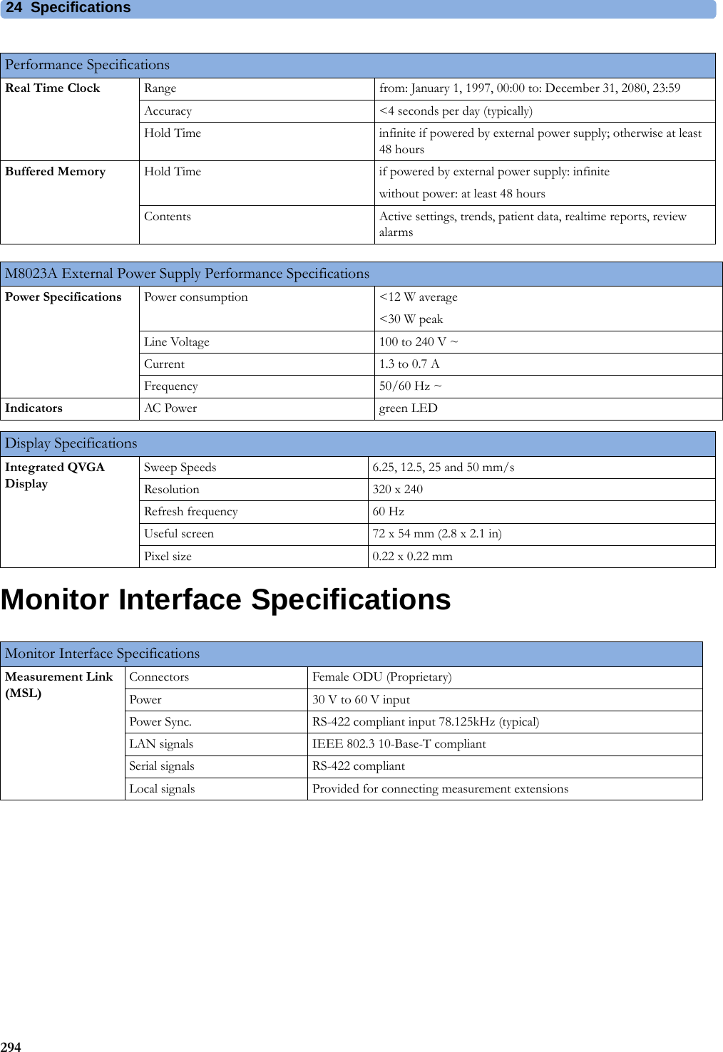
![4 Patient Alarms and INOPs75Temperature INOPsSpO2 INOPsINOP Message, Indication What to do T1, T2, T3, T4 INOPs See <Temp Label> INOPsTamb INOPs See <Temp Label> INOPsTart INOPs See <Temp Label> INOPsTcereb INOPs See <Temp Label> INOPsTcore INOPs See <Temp Label> INOPs<Temp Label> DeactivatedINOP toneA Temp measurement label in the measurement device has been deactivated, either by connecting a Pressure transducer in the shared Press/Temp socket, or by deactivating the label in the Measurement Selection window.The measurement automatically disappears from the display.To switch the measurement on again, either reconnect a Temp transducer or reactivate the measurement label in the Measurement Selection window.<Temp Label> Equip MalfNumeric is replaced by -?-INOP toneContact your service personnel.The temperature hardware is faulty.<Temp Label>NoTransducerNumeric is replaced by -?-INOP toneMake sure the Temp probe is connected to the MMS or module.If you silence this INOP, the measurement will be switched off.<Temp Label> OverrangeNumeric is replaced by -?-INOP toneTry changing the application site of the transducer.[The temperature is less than -1°C, or greater than 45°C.]<Temp Label> UnpluggedINOP toneA Temp measurement label has been deactivated, either by unplugging a module, or by deactivating the label in the Measurement Selection window.The measurement automatically disappears from the display.To switch the measurement on again, either replug the module or reactivate the measurement label in the Measurement Selection window.Tesoph INOPs See <Temp Label> INOPsTnaso INOPs See <Temp Label> INOPsTrect INOPs See <Temp Label> INOPsTskin INOPs See <Temp Label> INOPsTtymp INOPs See <Temp Label> INOPsTven INOPs See <Temp Label> INOPsTvesic INOPs See <Temp Label> INOPsINOP Message, Indication What to do <SpO₂ Label> DeactivatedINOP toneThe SpO2 measurement label in the measurement device has been deactivated by deactivating the label in the Measurement Selection window. The measurement automatically disappears from the display. To switch the measurement on again, reactivate the measurement label in the Measurement Selection window.<SpO₂ Label> Equip MalfNumeric is replaced by -?-INOP toneThe MMS or module is faulty. Unplug and replug the MMS or module. If the INOP persists, contact your service personnel.](https://usermanual.wiki/Philips-Medical-Systems-North-America/WLANBV3.user-manual-mp2-english/User-Guide-3422182-Page-75.png)
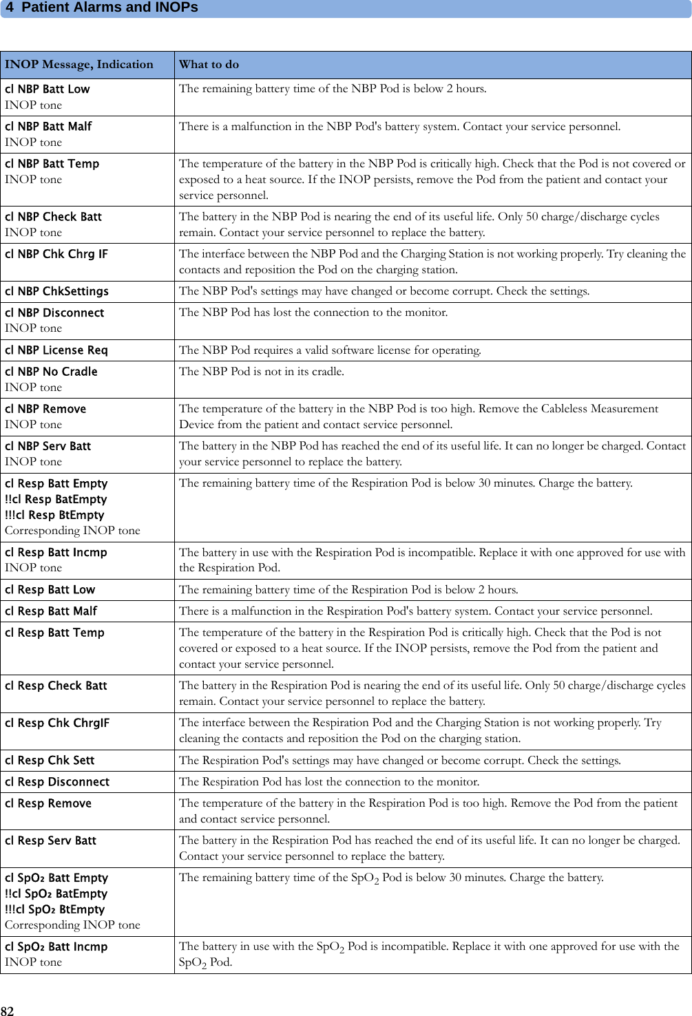

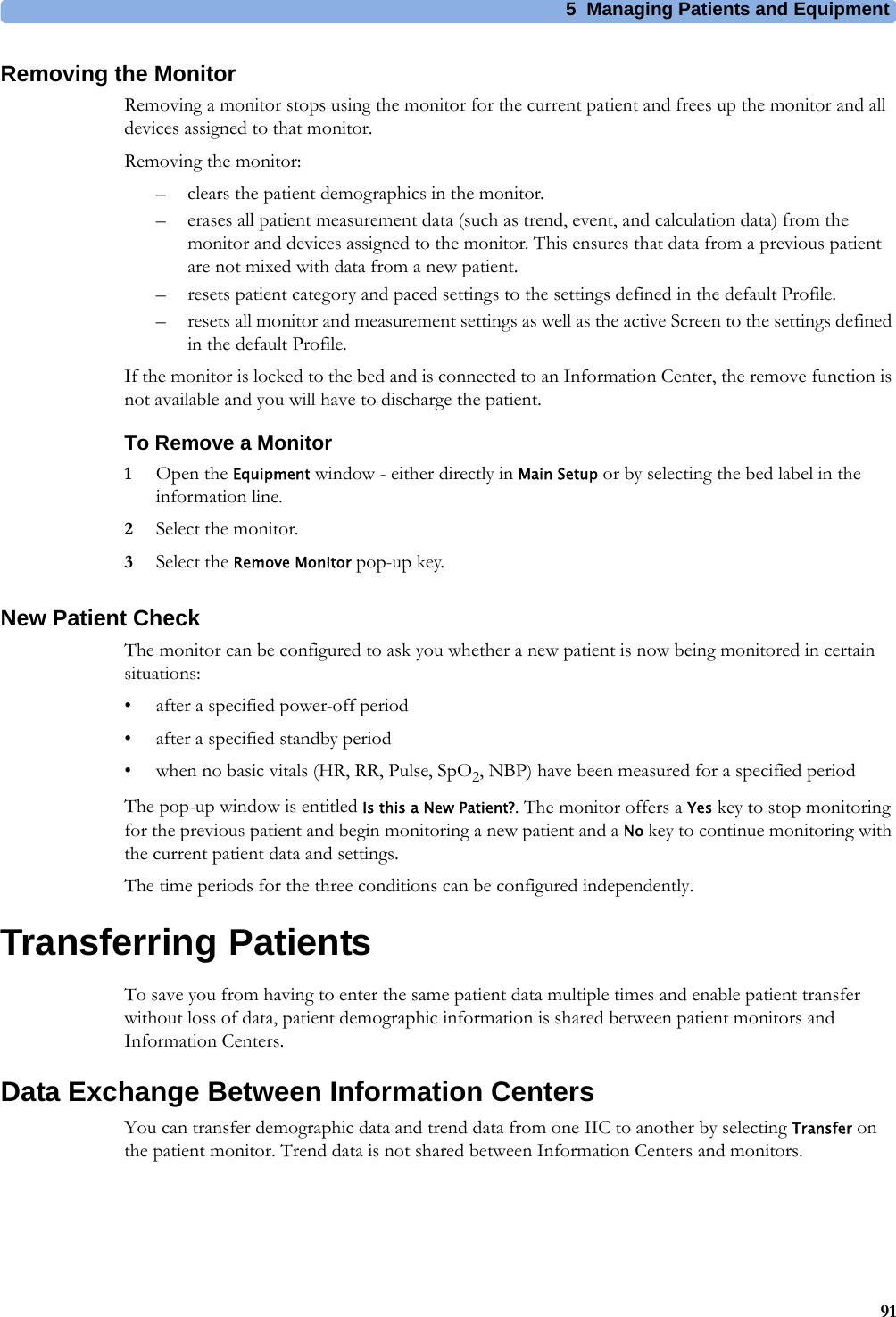
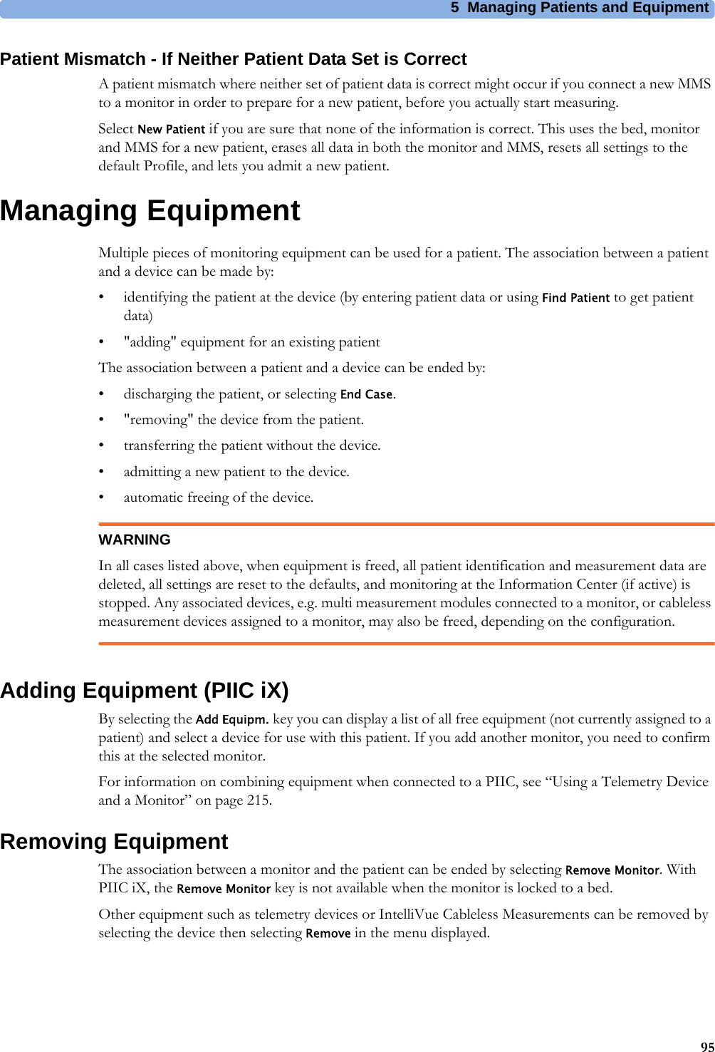
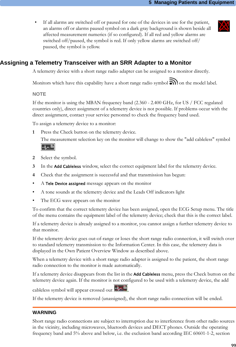
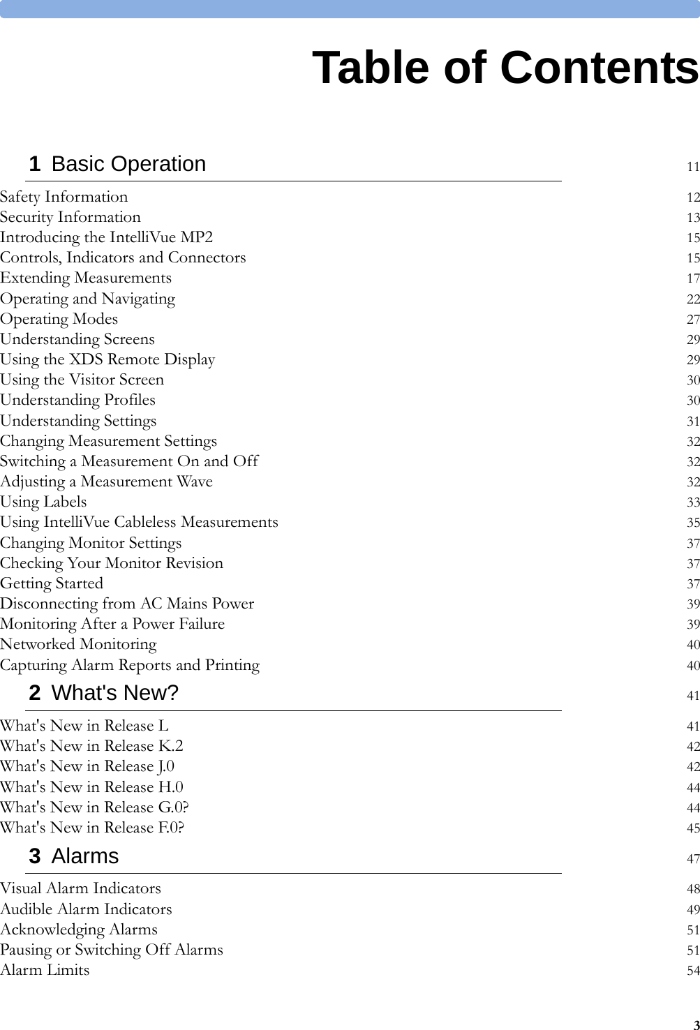
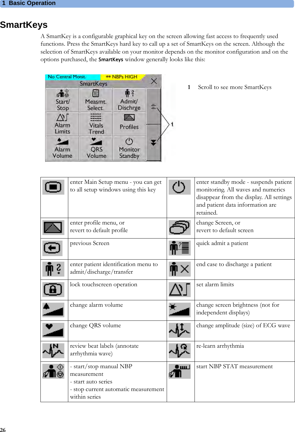
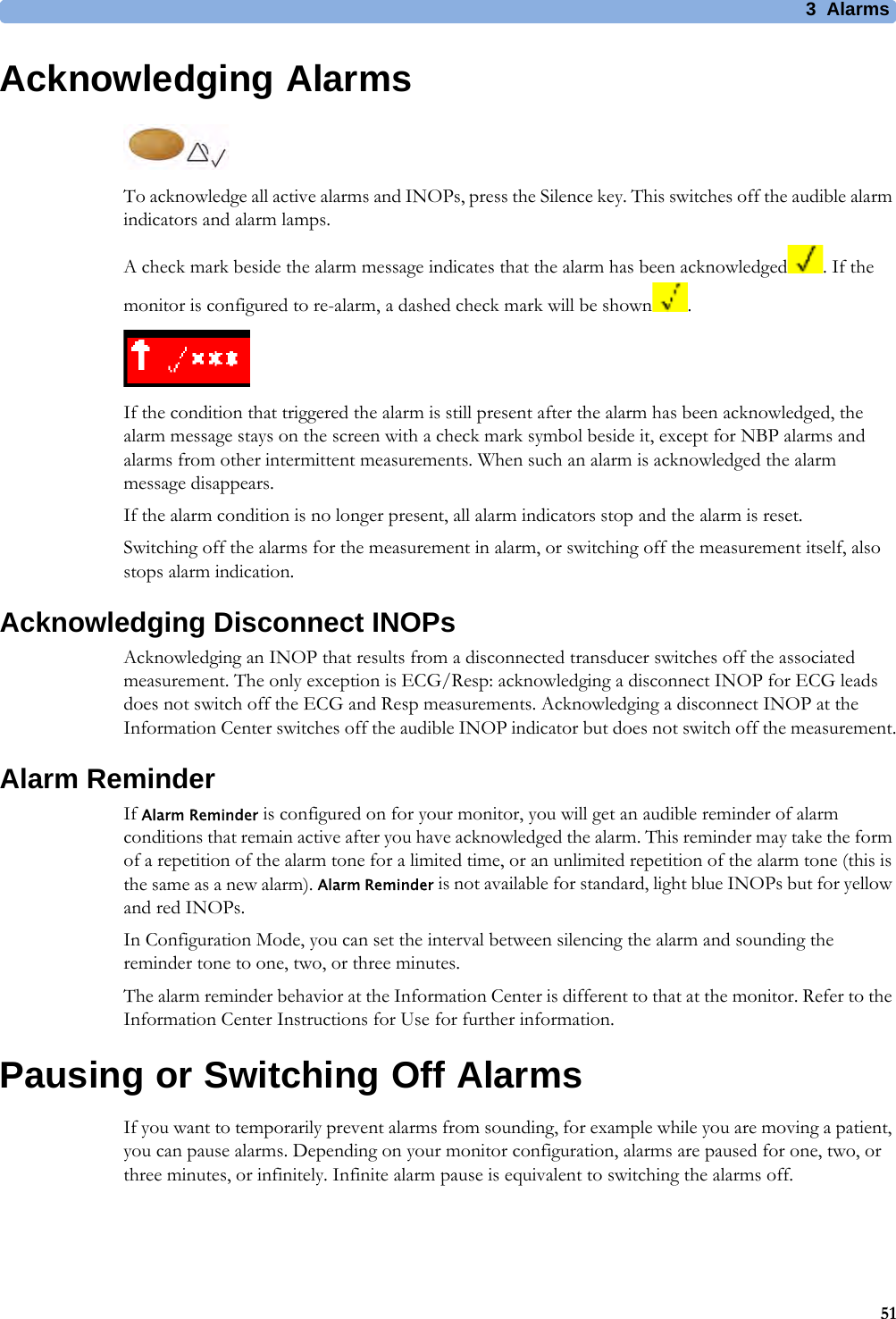
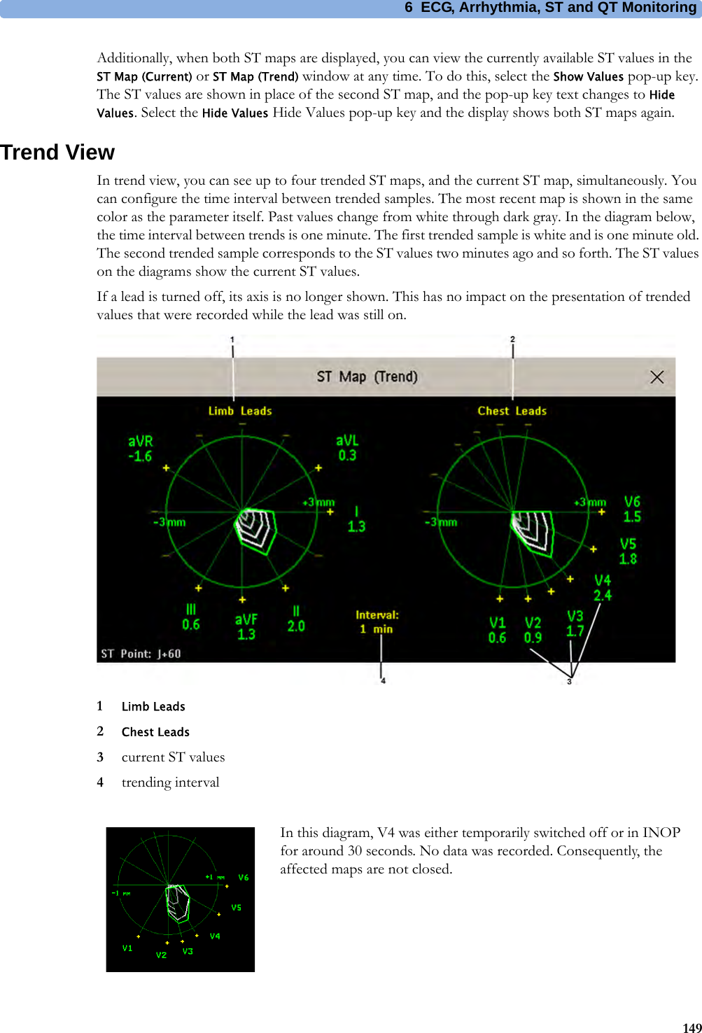
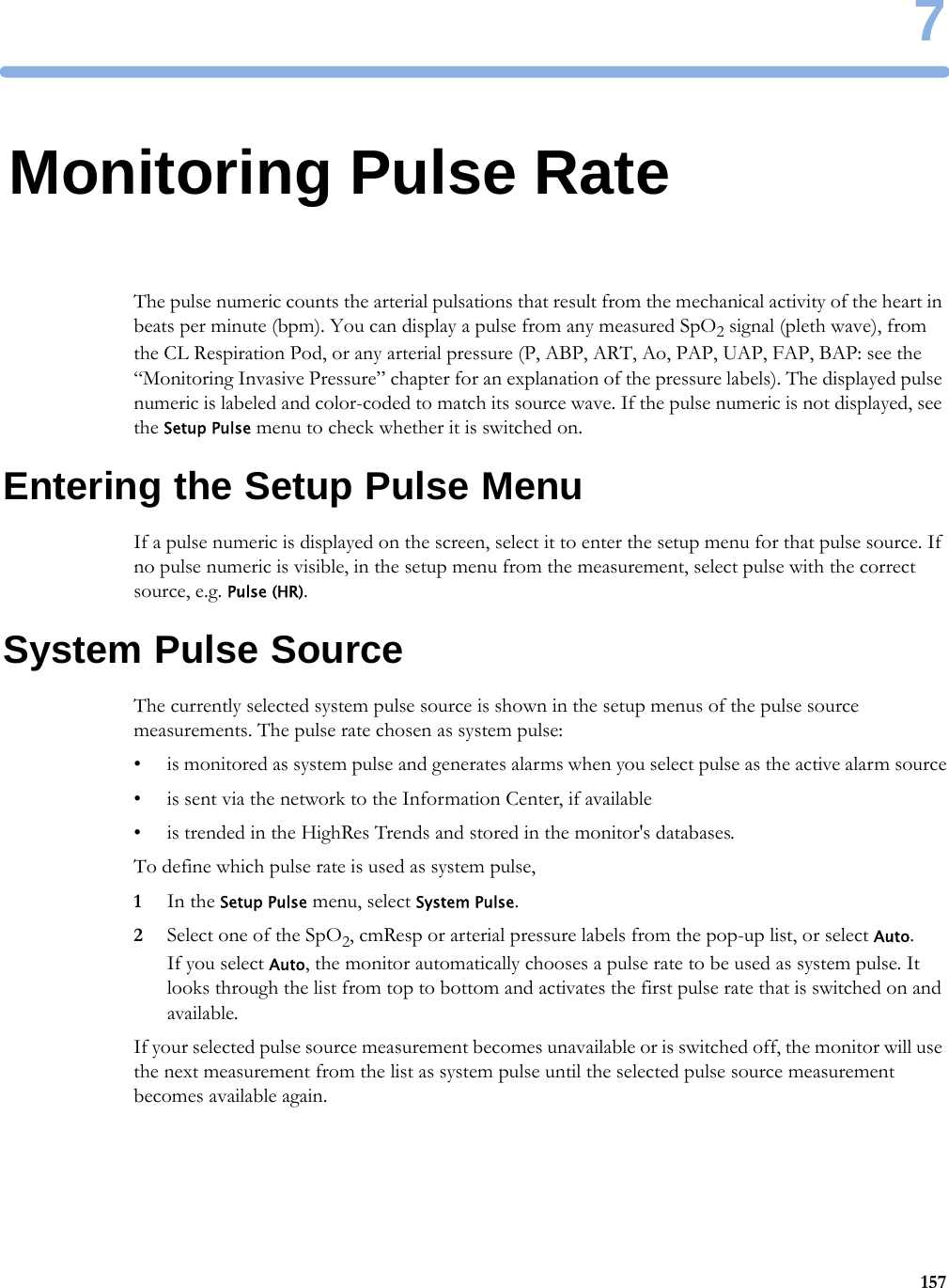
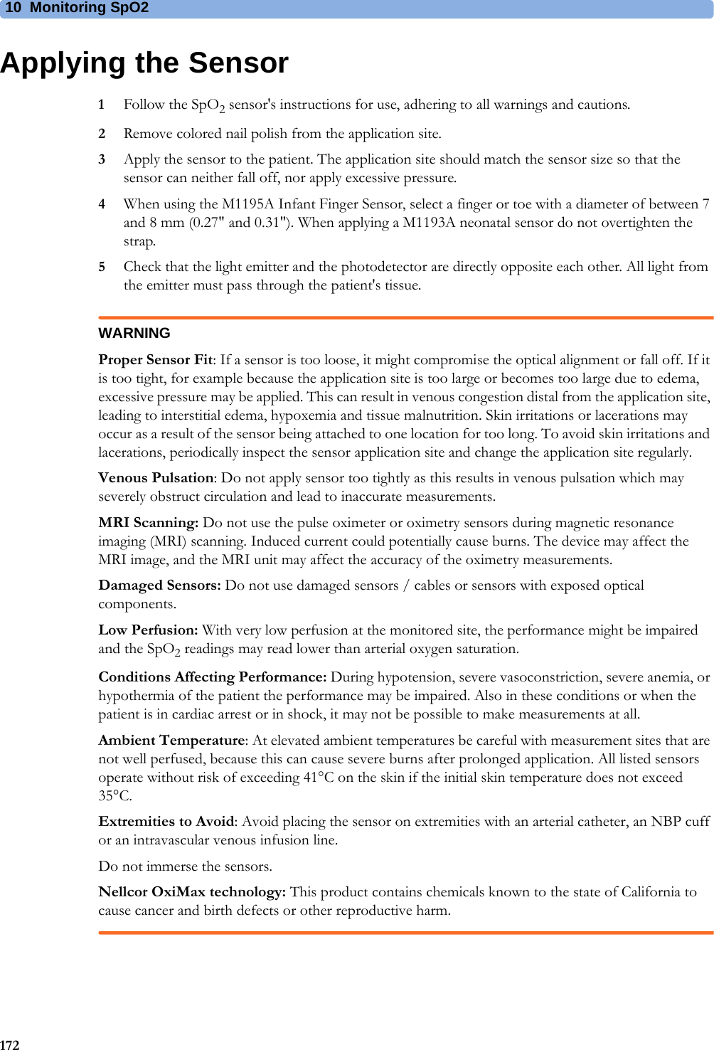
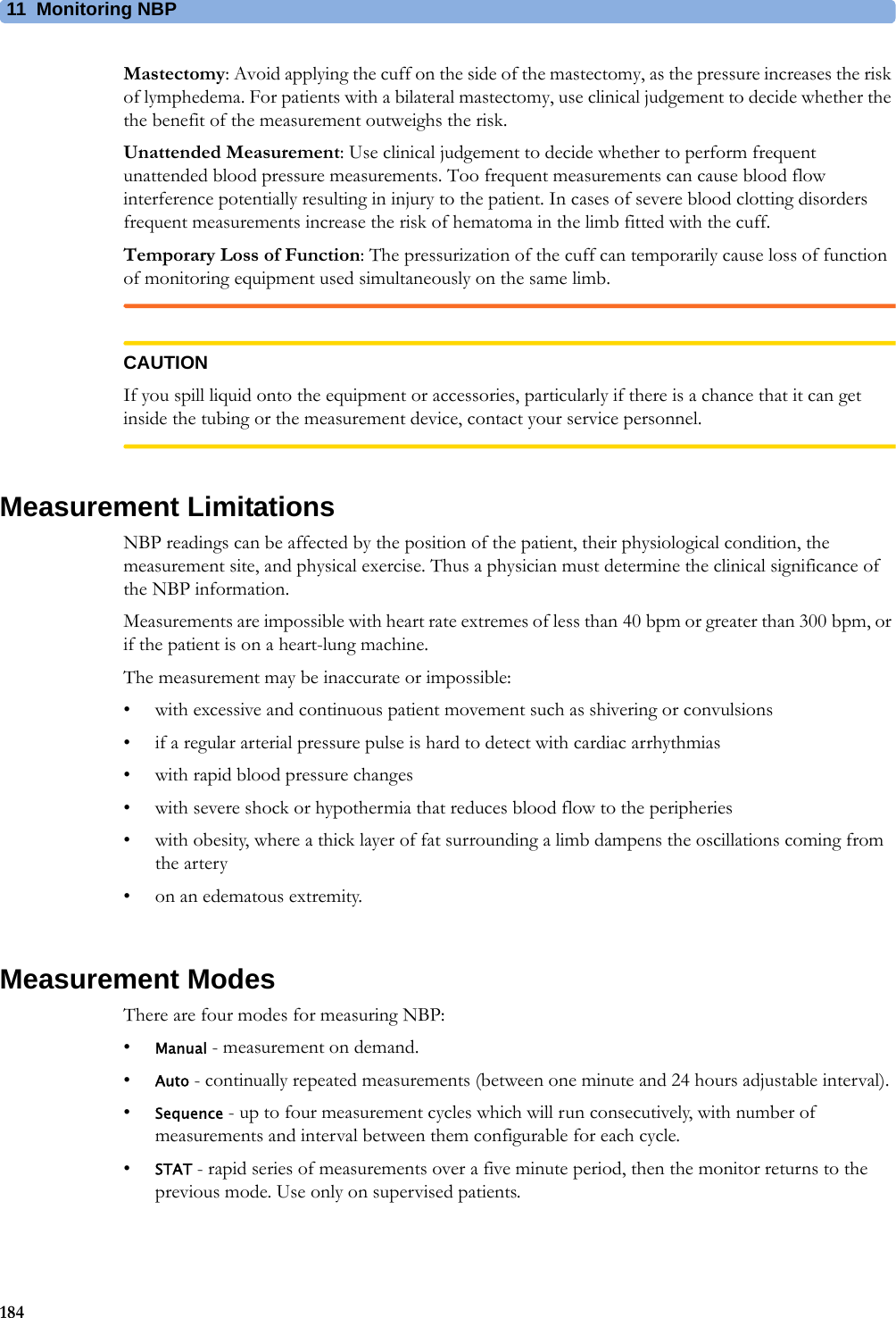
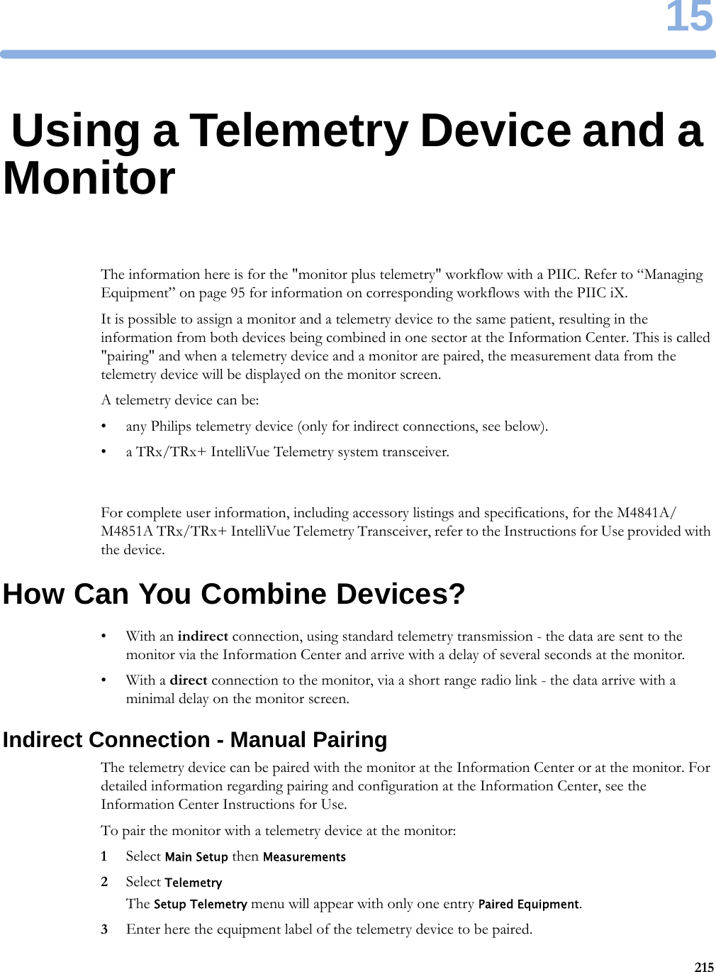
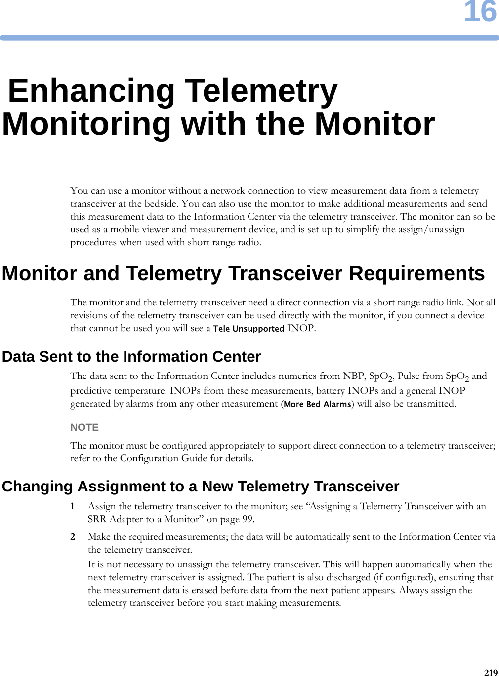
![5 Managing Patients and Equipment101Switching Off or Pausing Alarms From Other DevicesWhen you select Pause Alarms or Alarms Off at the monitor, the alarms are off or paused for the bedside measurements. When you switch alarms off or pause alarms at the Information Center, both monitor alarms and alarms from other assigned devices are affected.Refer to the Information Center Instructions for Use for more details on the Suspend/Pause alarms behavior of the Information Center.Using StandbyWhen you select Standby mode at the monitor, the bedside goes into Standby mode but other assigned devices may continue monitoring.Refer to the Information Center Instructions for Use for details on how selecting Standby at the Information Center affects the monitor and other devices.ECG Source Tracking at the Information CenterThe Information Center continuously checks whether a valid ECG signal is coming from the monitor or from another assigned device. If you unplug the ECG patient cable from the monitor and plug it into another device, the Information Center will automatically switch to monitoring the ECG from the other device. At the monitor, its own ECG measurement will be deactivated and the Setup ECG menu will no longer be accessible.When you unplug the patient cable from the other device and plug it back into the monitor again, the Information Center will switch back to monitoring the ECG from the monitor. The ECG measurement will be activated again at the monitor. [Note that in this case, as the screen switches back to the monitor's own measurements, the SpO2T measurement (if present) will no longer be displayed].In the same way the source is tracked when a telemetry device is directly connected to a monitor, then disconnected and vice versa.In case of ambiguity, a yellow INOP message !!Check ECG Source indicates that more than one valid ECG source is active.Synchronized SettingsFor some measurements, settings can be synchronized between the monitor and another measurement device. For example, if ECG is measured at the monitor, and then the patient is connected to a telemetry device for monitoring, the Information Center will use the monitor settings for the telemetry device. In general, the following settings will be synchronized:Heart Rate HR/Pulse Alarm On/Off, Heart Rate High/Low LimitECG ECG On/Off1, Primary Lead, Secondary Lead, Va Lead, Vb Lead, Lead PlacementArrhythmia Analysis Mode, Arrhythmia On/Off, Asystole Threshold, Pause Threshold, VTach HR, VTach Run, PVCs/min, Vent. Rhythm, SVT HR, SVT Run, PVCs/min On/Off, Pacer not capture On/Off, Pacer not pace On/Off, Non-Sustain On/Off, Vent. Rhythm On/Off, Run PVCs On/Off, Pair PVCs On/Off, Missed Beat On/Off, Pause On/Off, R-on-T PVCs On/Off, Vent. Bigeminy On/Off, Vent. Trigeminy On/Off, Multiform PVCs On/Off, Irregular HR On/Off, SVT On/Off, Afib On/Off, Afib/IrrHR End Threshold, All ECG Alarm INOP mode.](https://usermanual.wiki/Philips-Medical-Systems-North-America/WLANBV3.user-manual-mp2-english/User-Guide-3422182-Page-101.png)

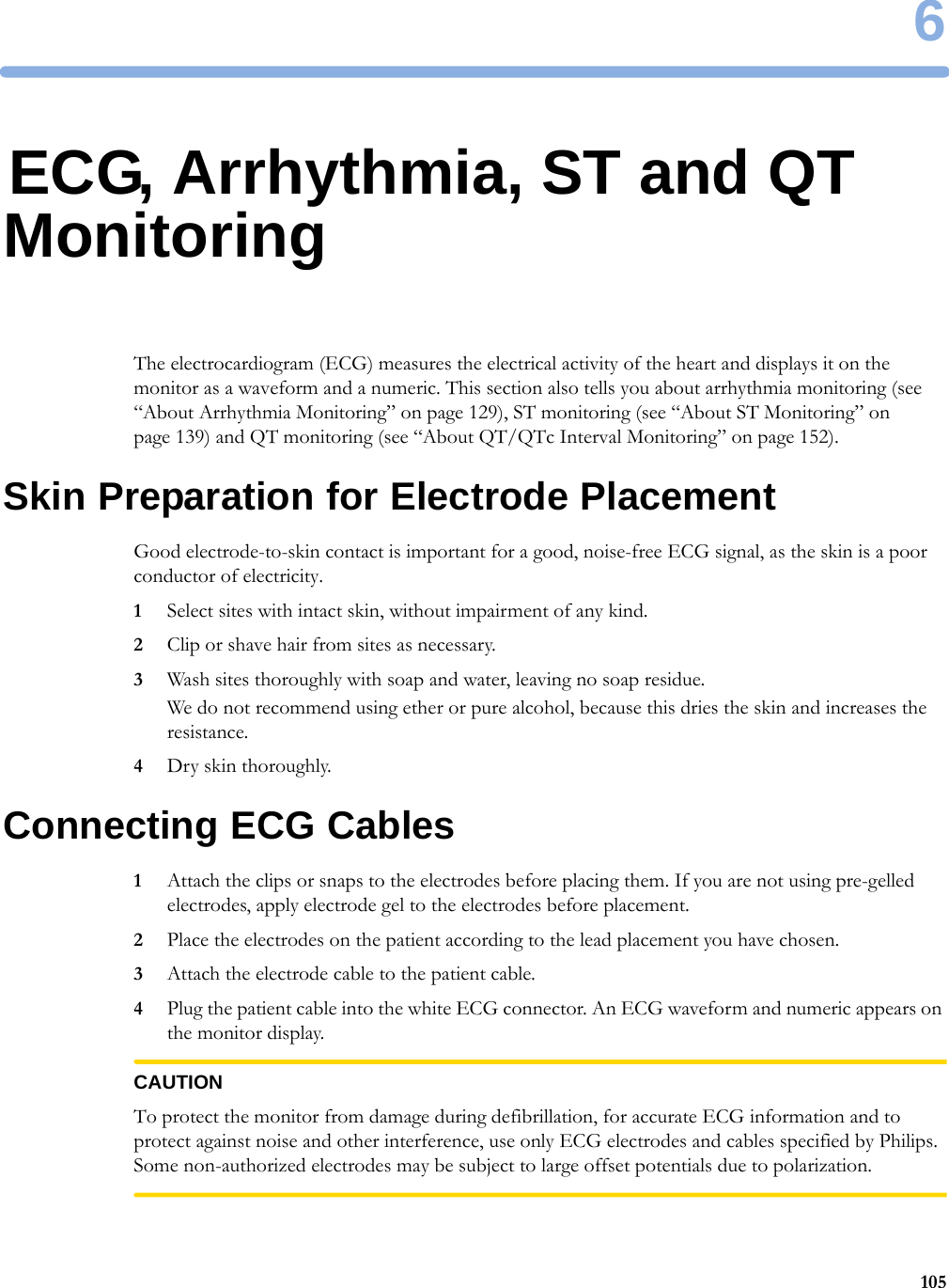

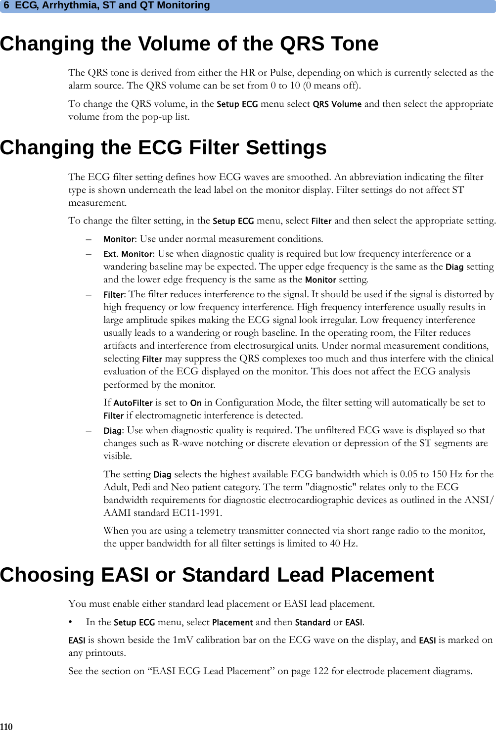


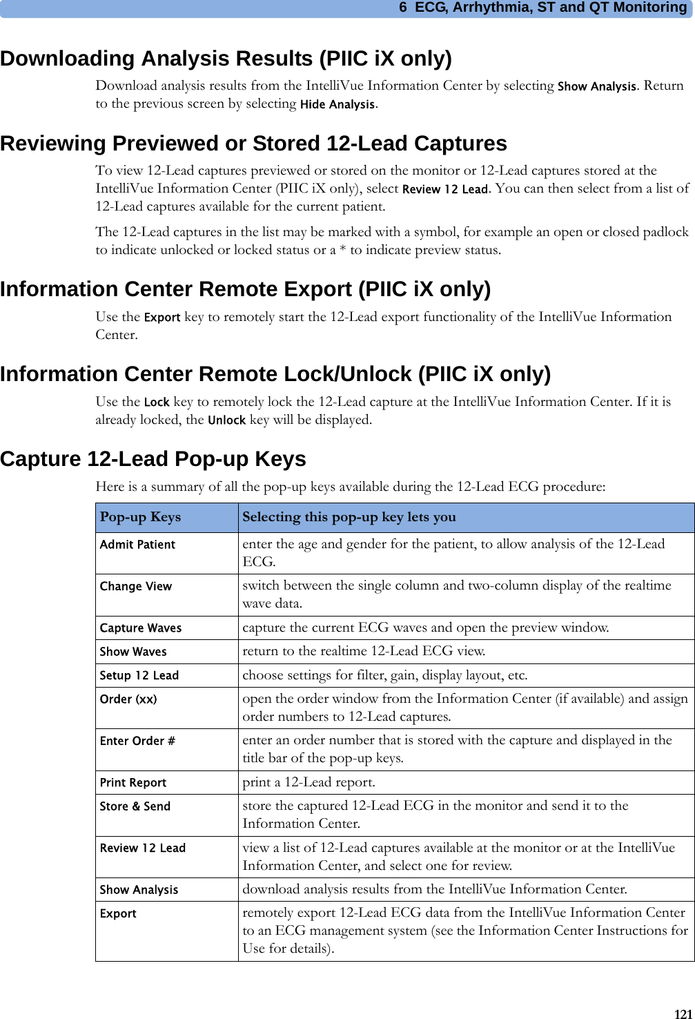
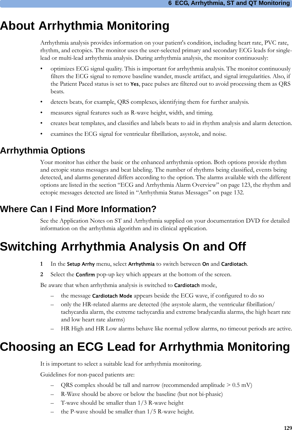
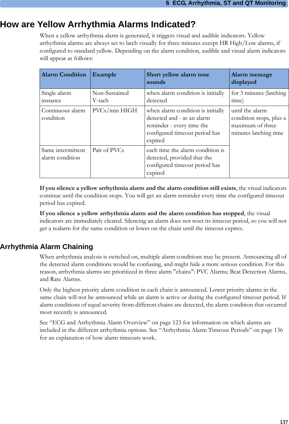
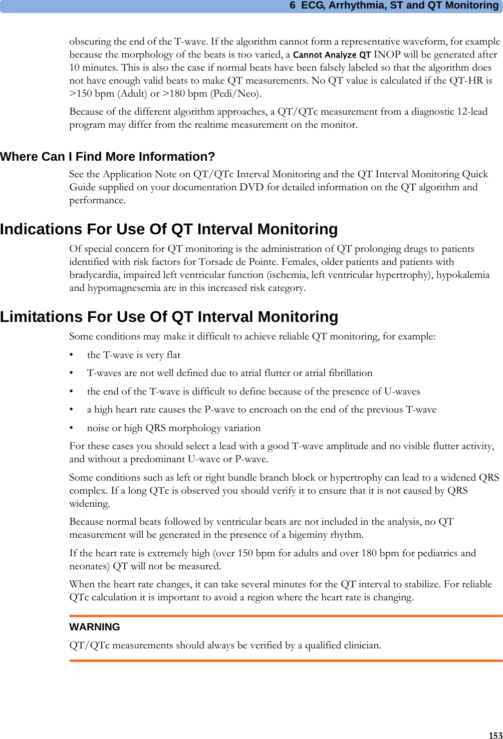


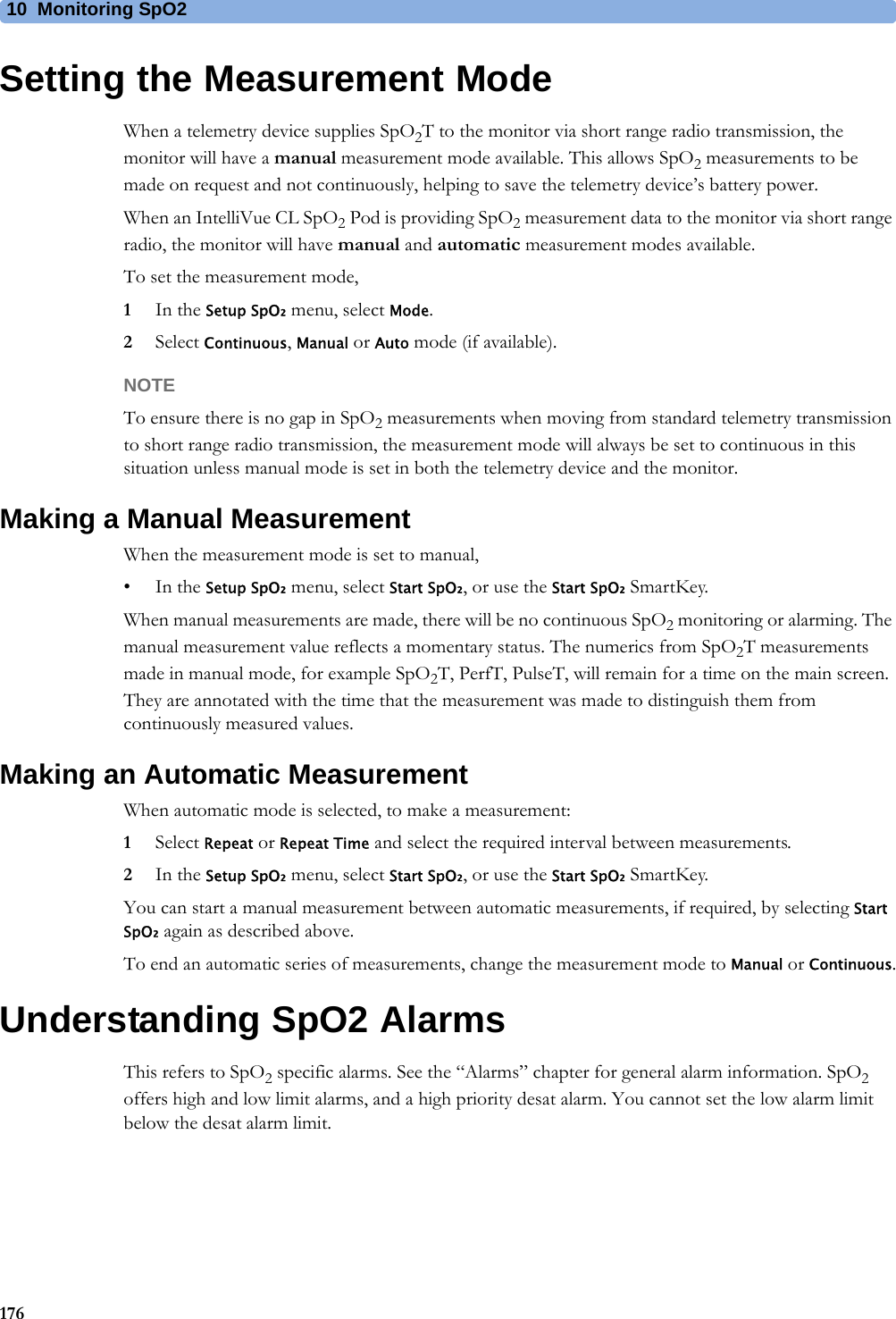
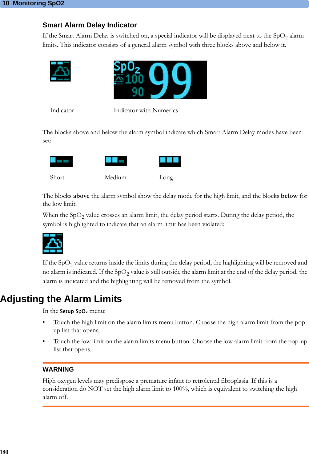
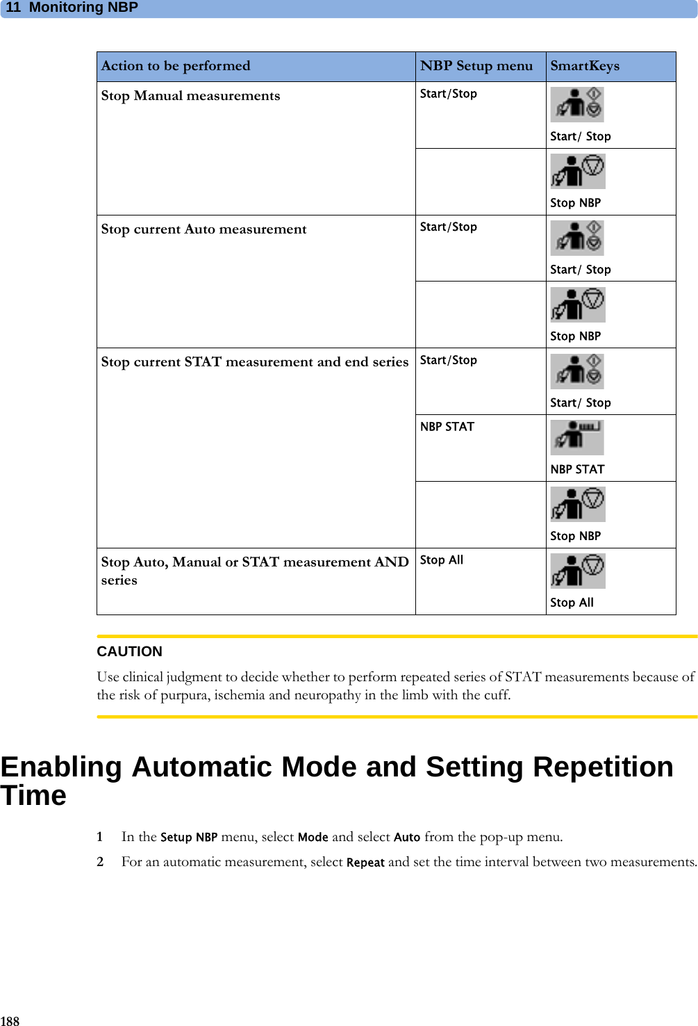
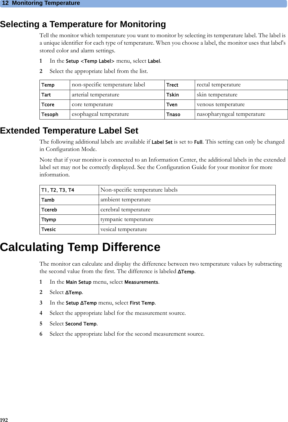
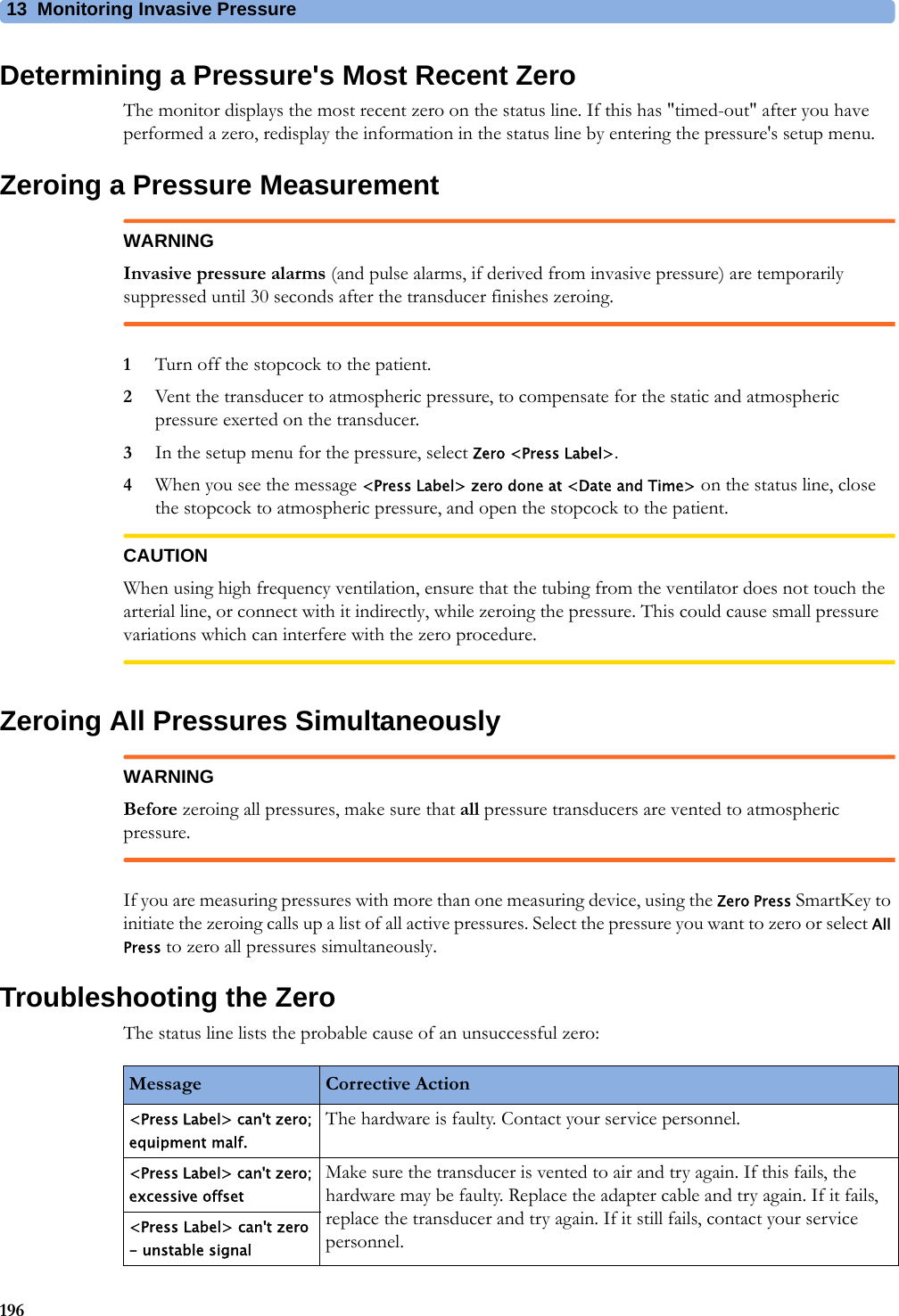
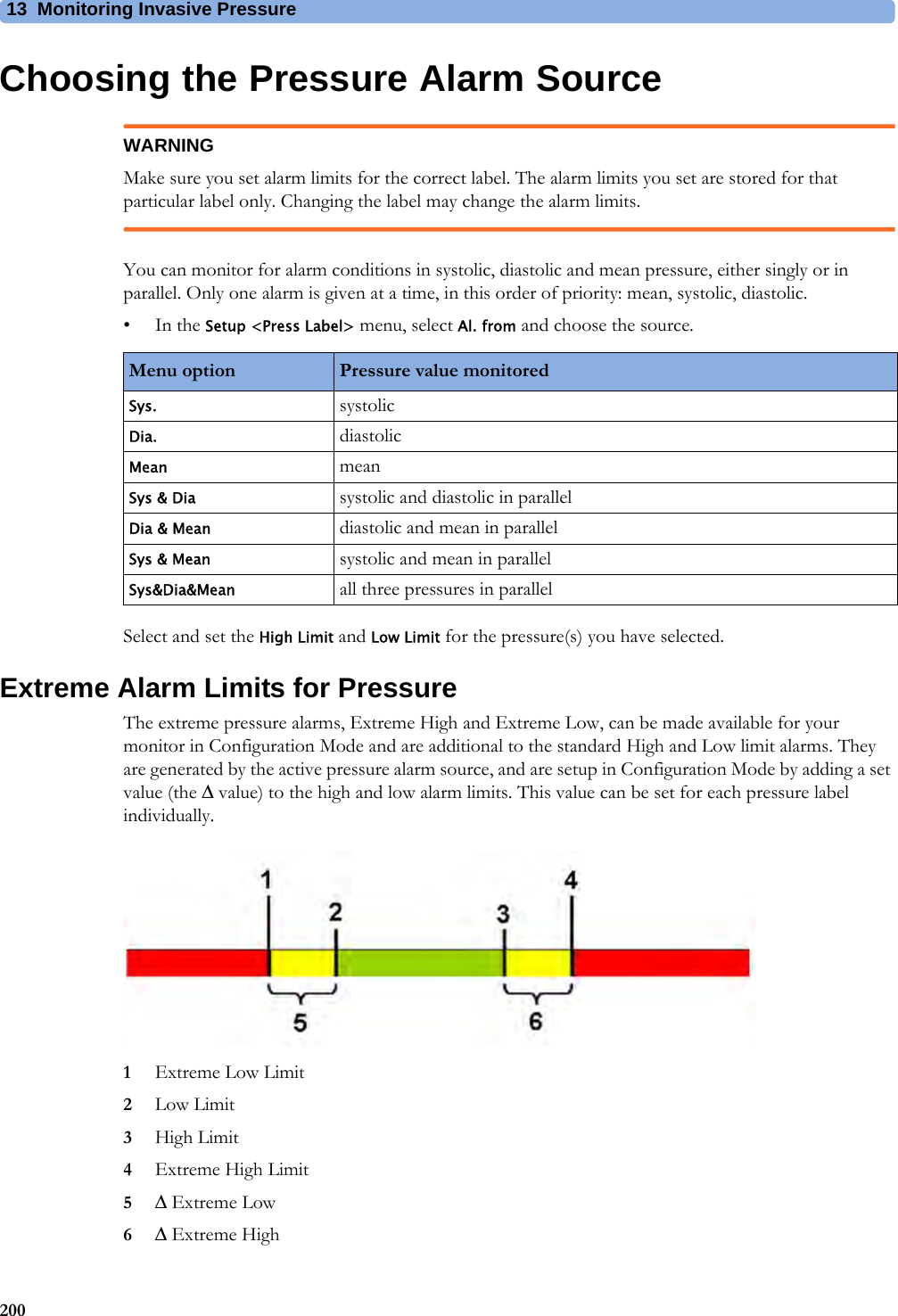


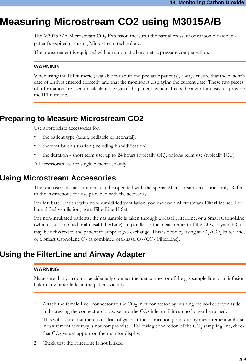


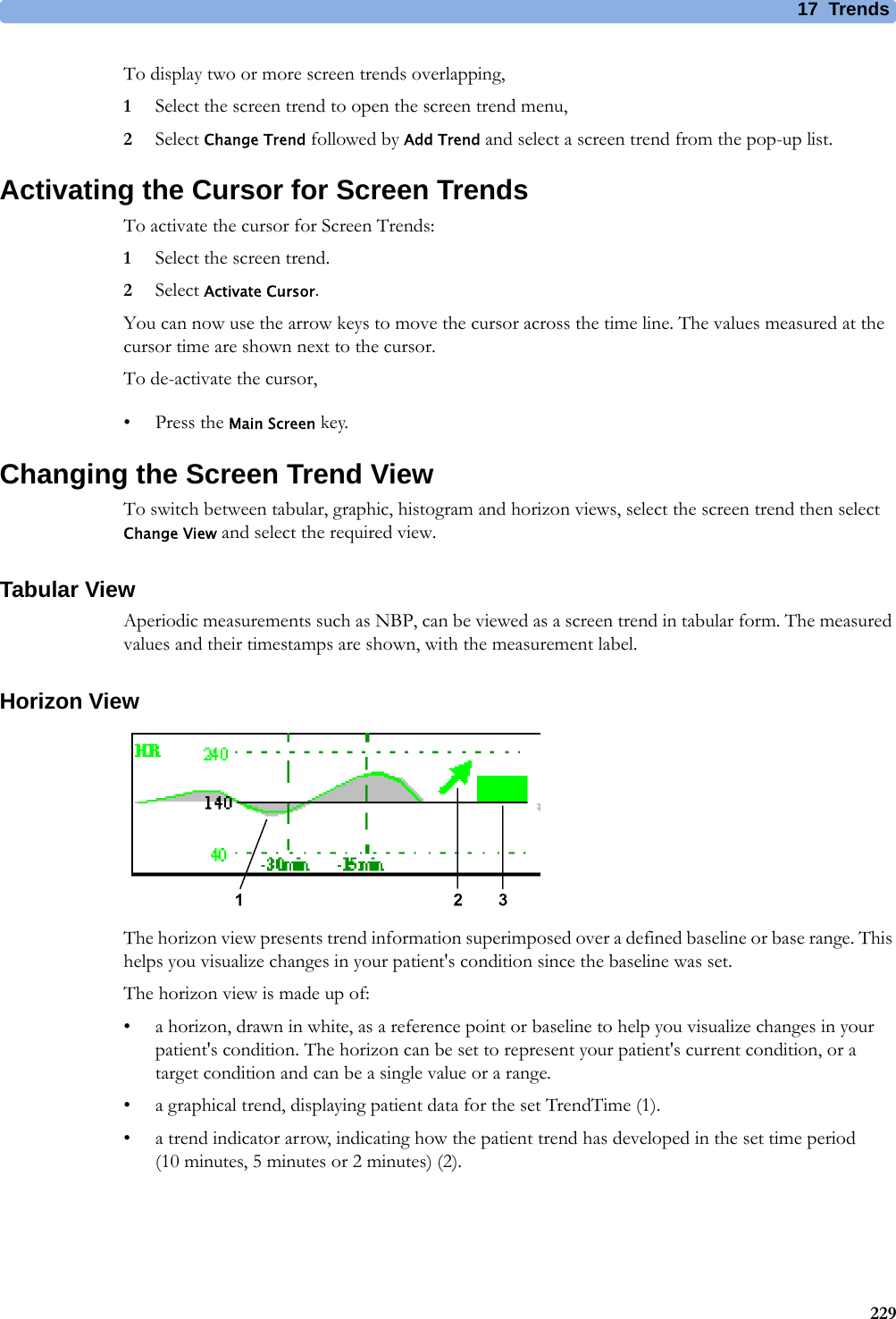


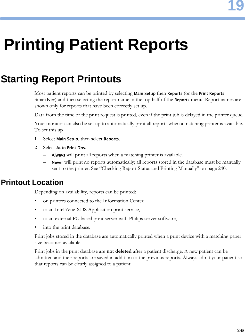
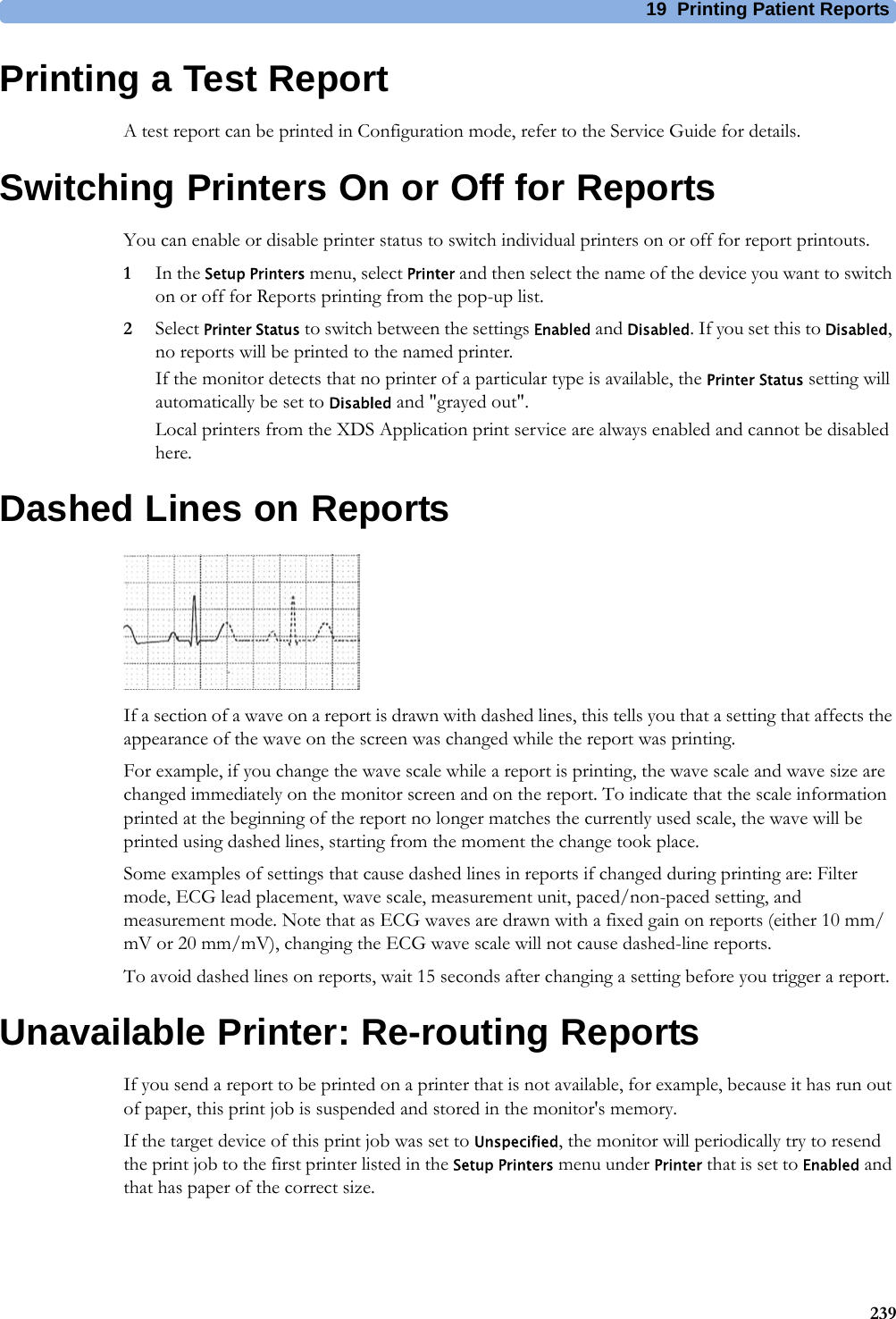


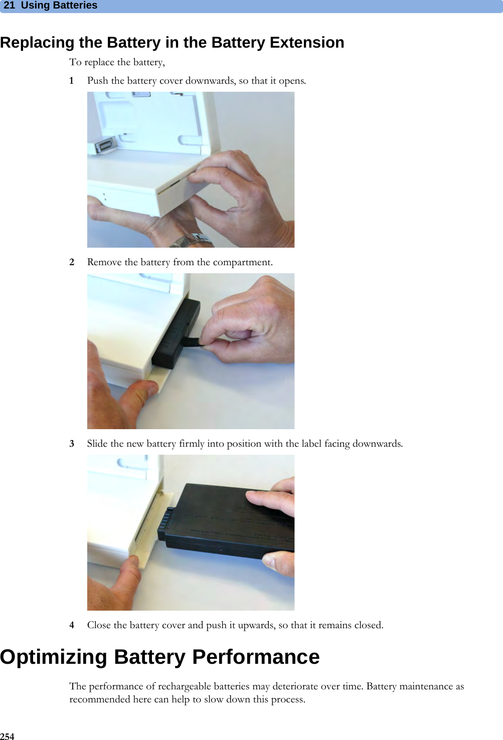


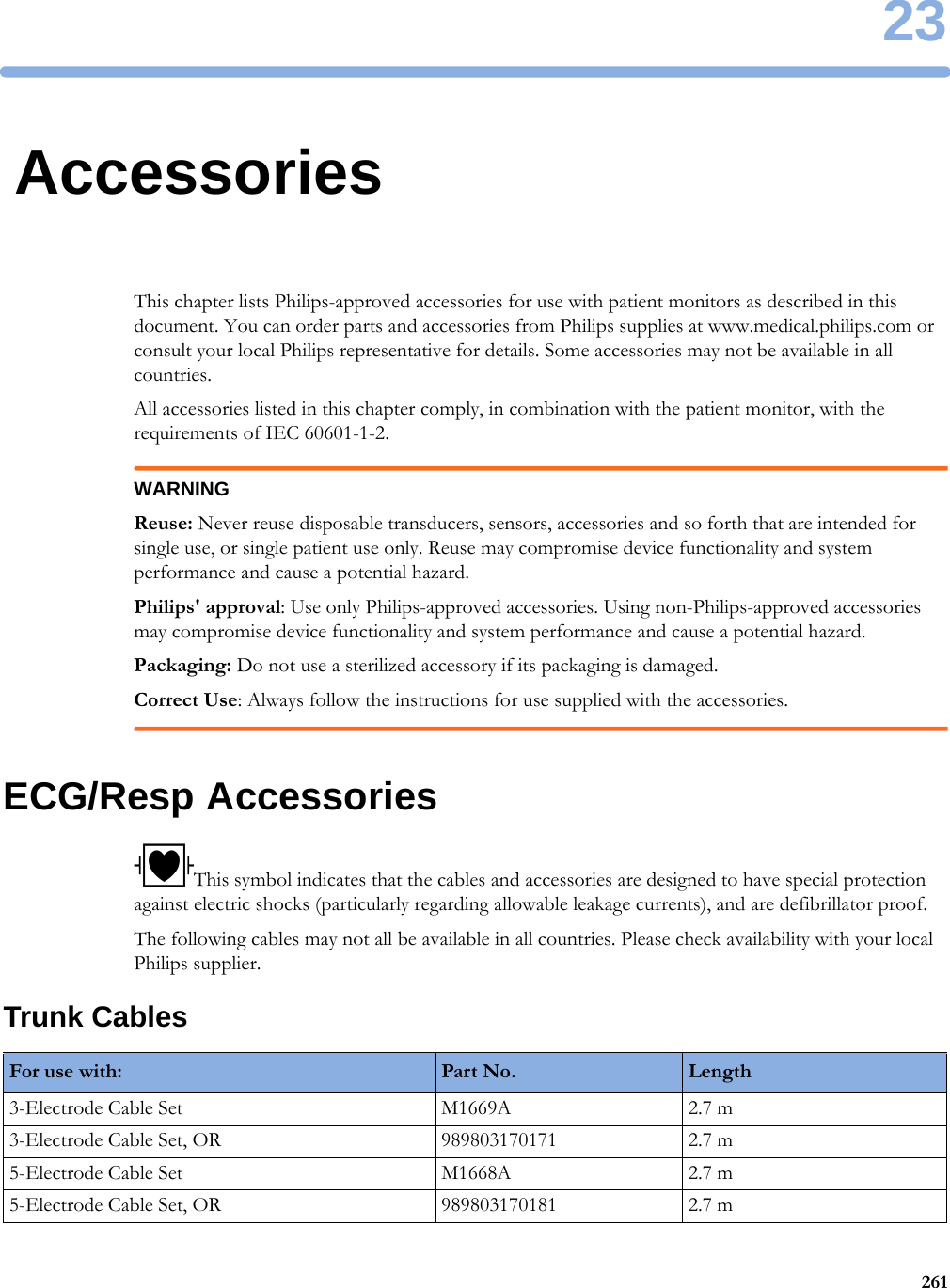
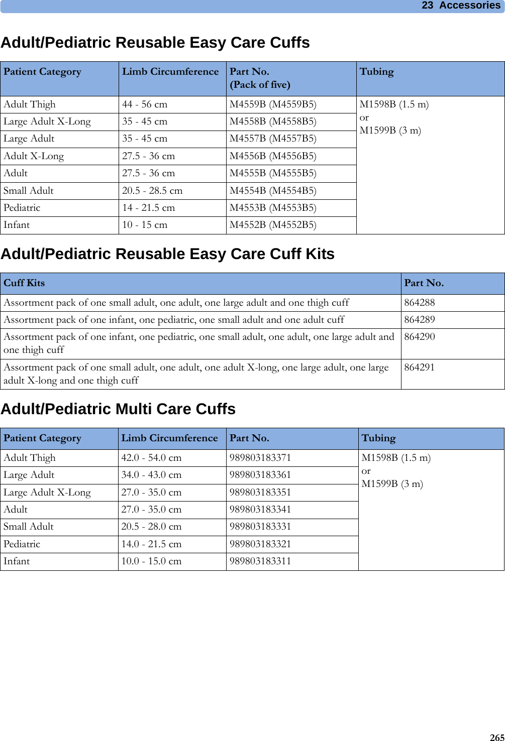
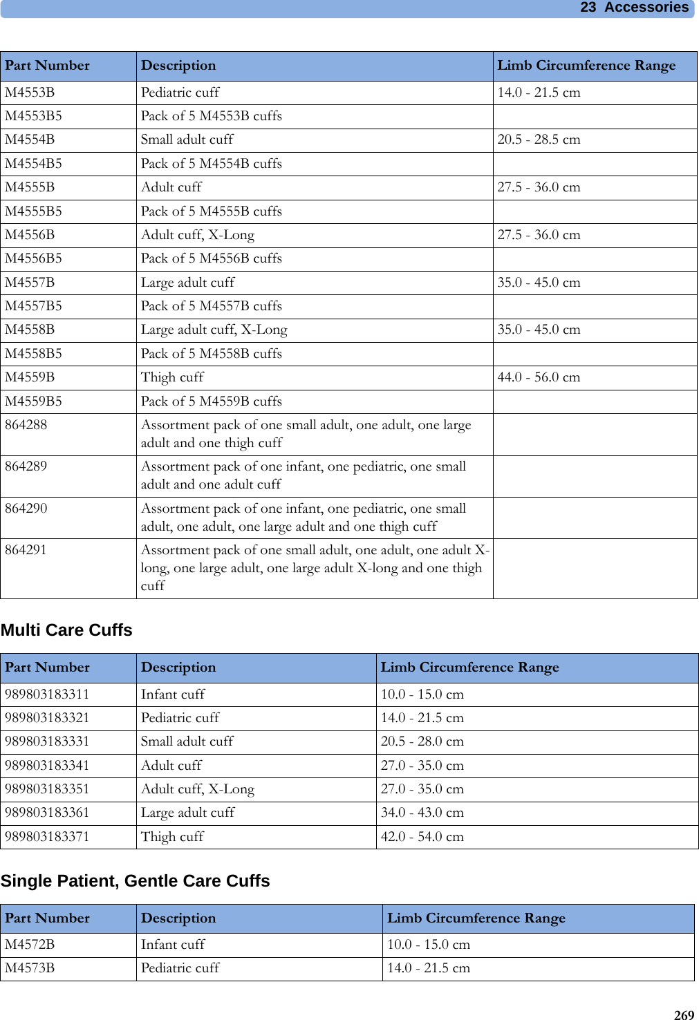
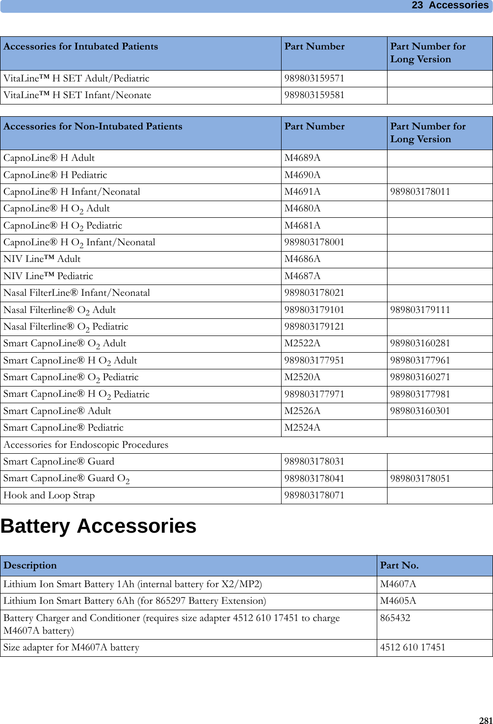


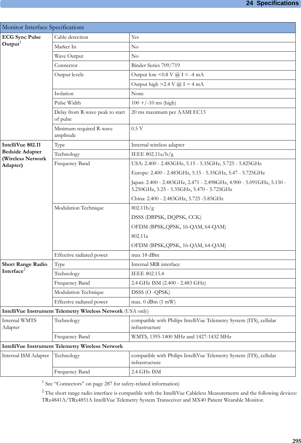
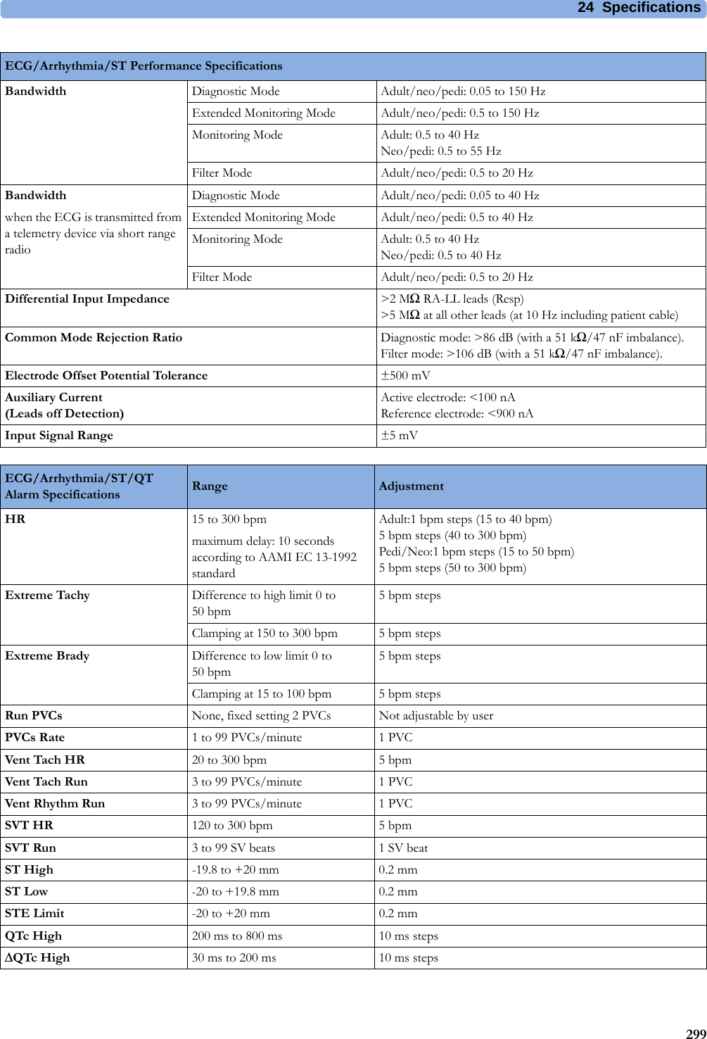
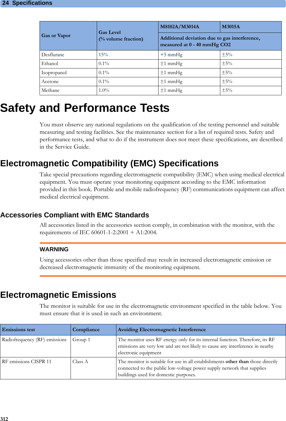
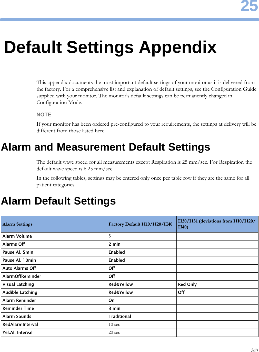
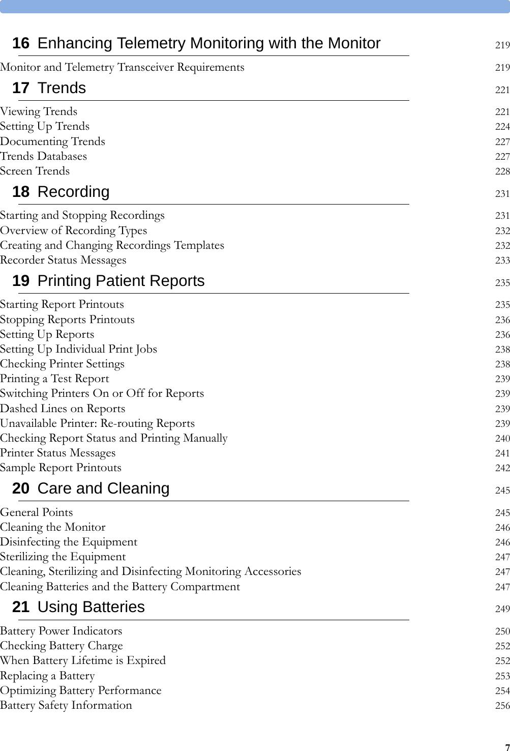
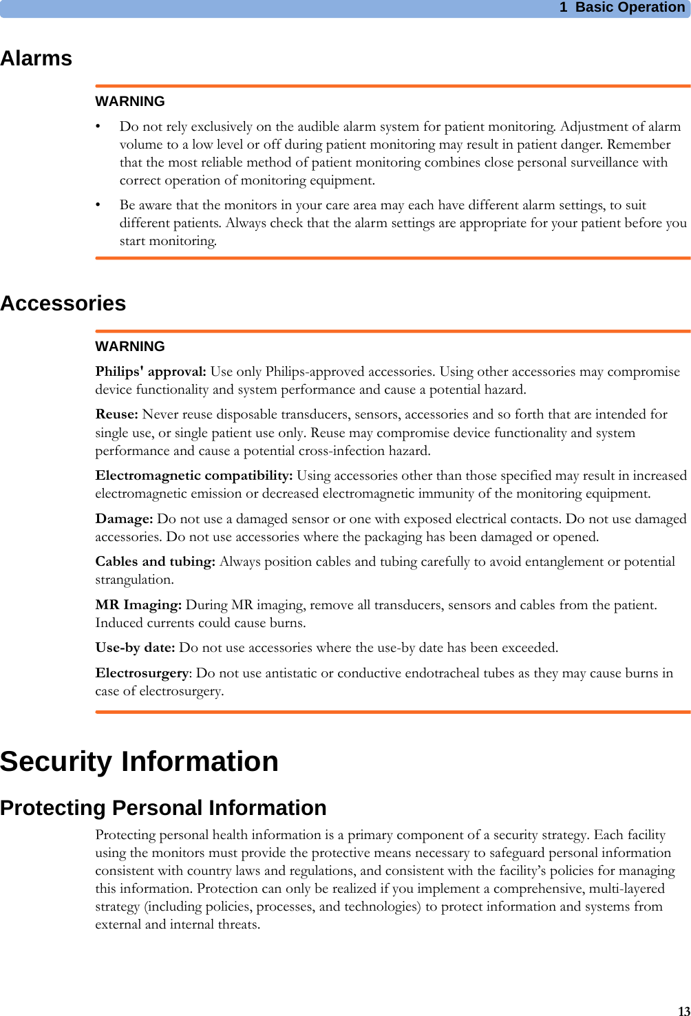
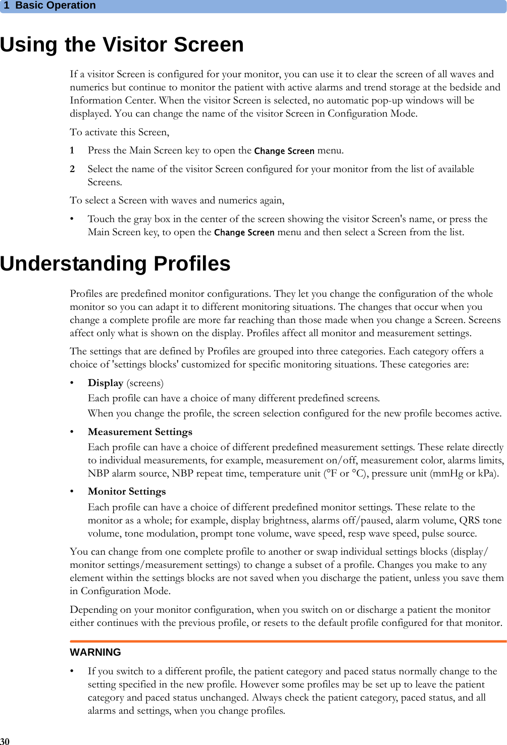
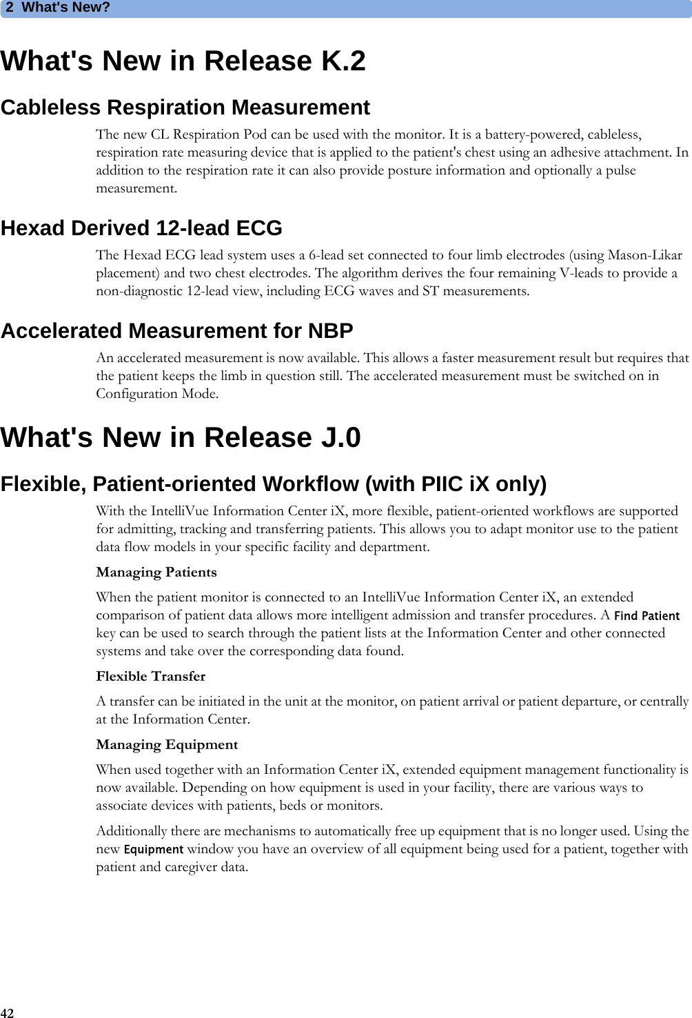
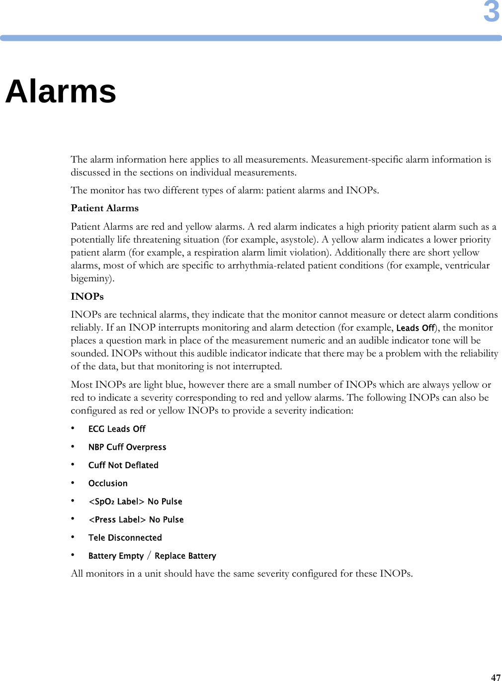
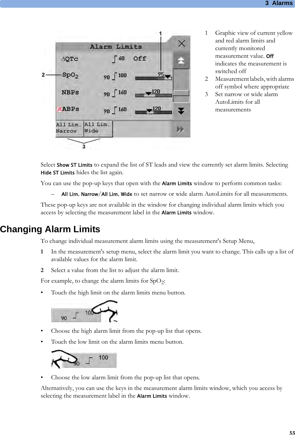
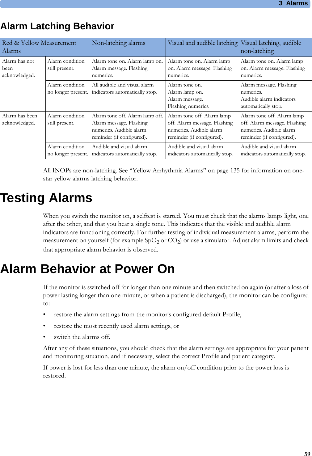
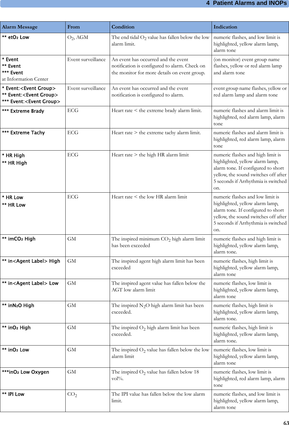
![24 Specifications300RespirationECG/Arrhythmia/ST Supplemental Information as required by AAMI EC11/13, IEC 60601-2-27Respiration Excitation Waveform Sinusoidal signal, 260 μA, 40.5 kHzNoise Suppression RL drive gain 44 dB max., max. voltage 1.8 VrmsTime to Alarm for Tachycardia Vent Tachycardia1mVpp,206 bpmGain 0.5, Range 6.5 to 8.4 seconds, Average 7.2 secondsGain 1.0 Range 6.1 to 6.9 seconds, Average 6.5 secondsGain 2.0, Range 5.9 to 6.7 seconds, Average 6.3 secondsVent Tachycardia2mVpp,195 bpmGain 0.5, Range 5.4 to 6.2 seconds, Average 5.8 secondsGain 1.0, Range 5.7 to 6.5 seconds, Average 6.1 secondsGain 2.0, Range 5.3 to 6.1 seconds, Average 5.7 secondsTall T-Wave Rejection Capability Exceeds ANSI/AAMI EC 13 Sect. 3.1.2.1(c) minimum recommended 1.2 mV T-Wave amplitudeHeart Rate Averaging Method Three different methods are used:Normally, heart rate is computed by averaging the 12 most recent R-R intervals.For runs of PVCs, up to 8 R-R intervals are averaged to compute the HR.If each of 3 consecutive R-R intervals is greater than 1200 ms (that is, rate less than 50 bpm), then the 4 most recent R-R intervals are averaged to compute the HR.Response Time of Heart Rate Meter to Change in Heart Rate HR change from 80 to 120 bpm:Range: [6.4 to 7.2 seconds] Average: 6.8 secondsHR change from 80 to 40 bpm:Range: [5.6 to 6.4 sec] Average: 6.0 secondsHeart Rate Meter Accuracy and Response to Irregular Rhythm Ventricular bigeminy: 80 bpmSlow alternating ventricular bigeminy: 60 bpmRapid alternating ventricular bigeminy: 120 bpmBidirectional systoles: 90 bpmAccuracy of Input Signal Reproduction Methods A and D were used to establish overall system error and frequency response.Pacemaker Pulse Rejection Performance Rejection of pacemaker pulses with amplitudes from ±2 mV to ±700 mV and widths from 0.1 ms to 2.0 ms (Method A)Pacemaker Pulse Rejection of fast ECG signals 2.2 V/s RTI (Paced Mode)Minimum input slew rate 2.2 V/s RTIRespiration Performance SpecificationsRespiration Rate Range Adult/pedi: 0 to 120 rpmNeo: 0 to 170 rpmAccuracy at 0 to 120 rpm ±1 rpmat 120 to 170 rpm ±2 rpmResolution 1 rpmBandwidth 0.3 to 2.5 Hz (-6 dB)Noise Less than 25 mΩ (rms) referred to the input](https://usermanual.wiki/Philips-Medical-Systems-North-America/WLANBV3.user-manual-mp2-english/User-Guide-3422182-Page-300.png)