Prodrive Technologies SC2MCSIO SC2MCSIO RFID User Manual
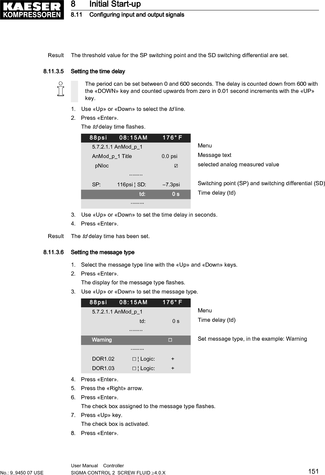
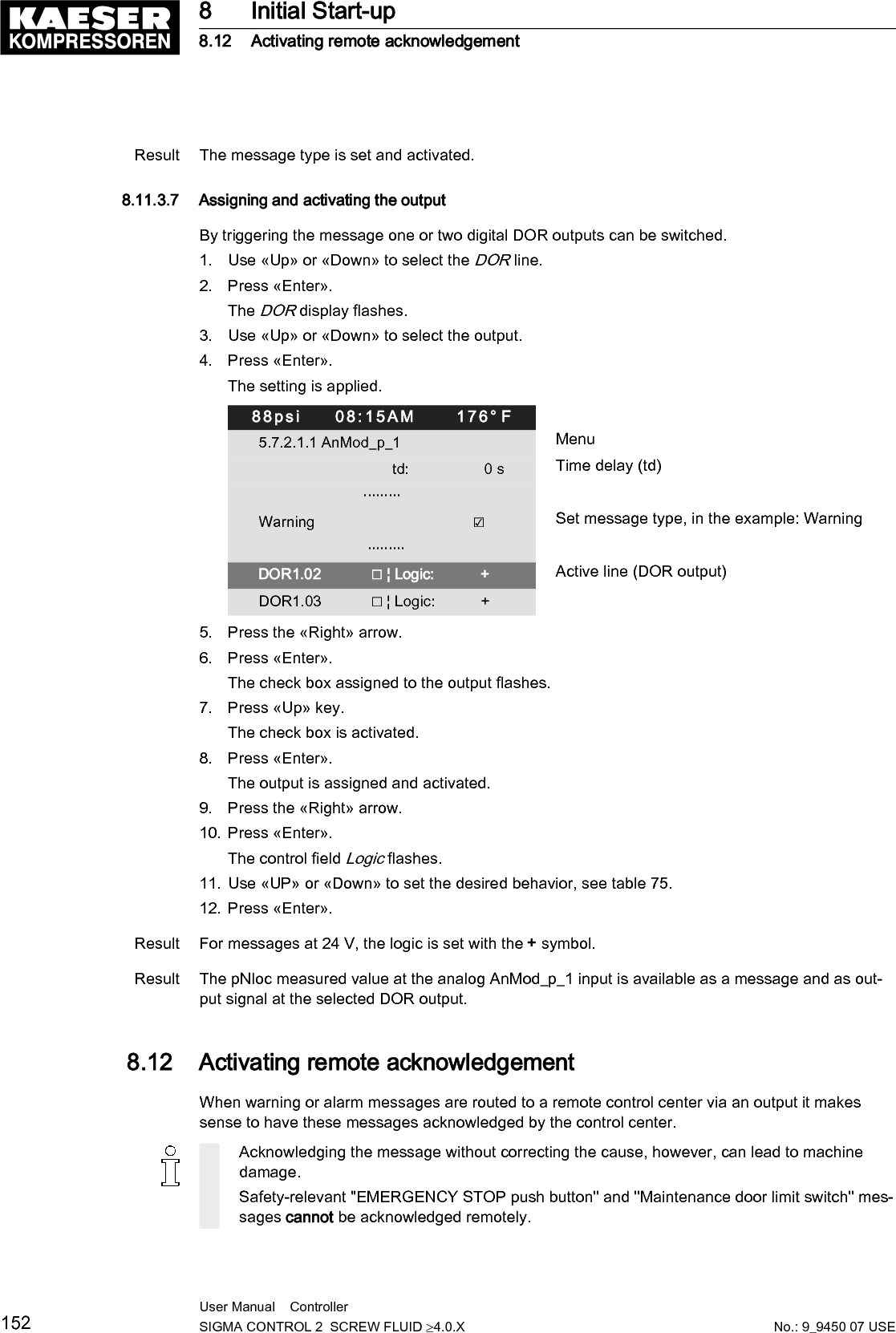
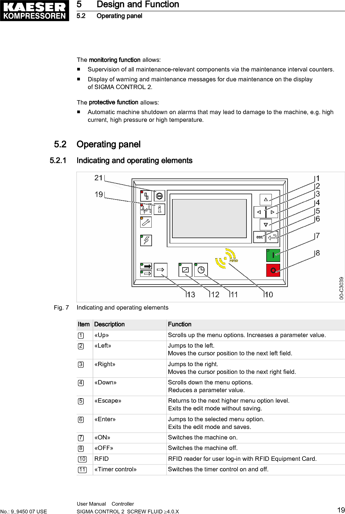
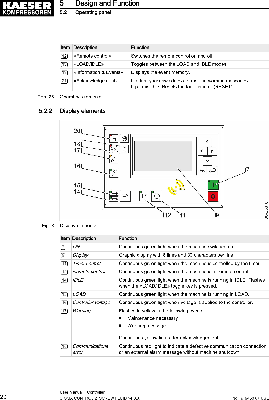
Prodrive Technologies B.V. SC2MCSIO RFID Users Manual
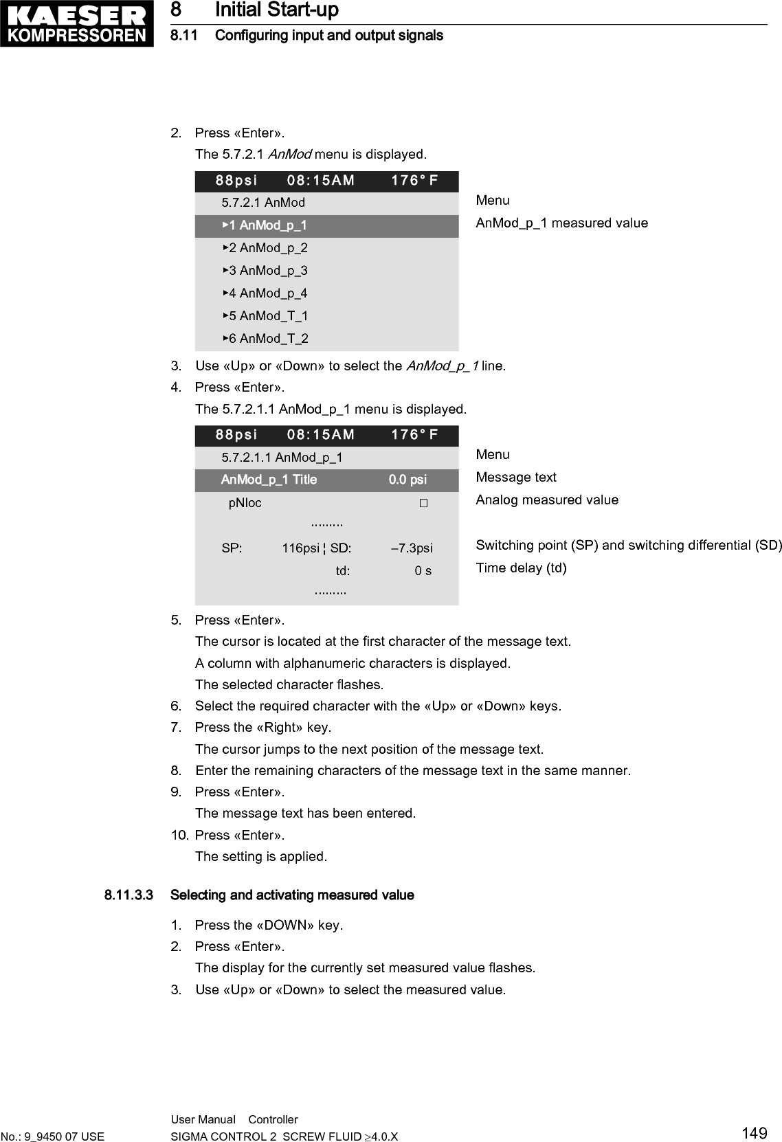
UserManual.wiki
>
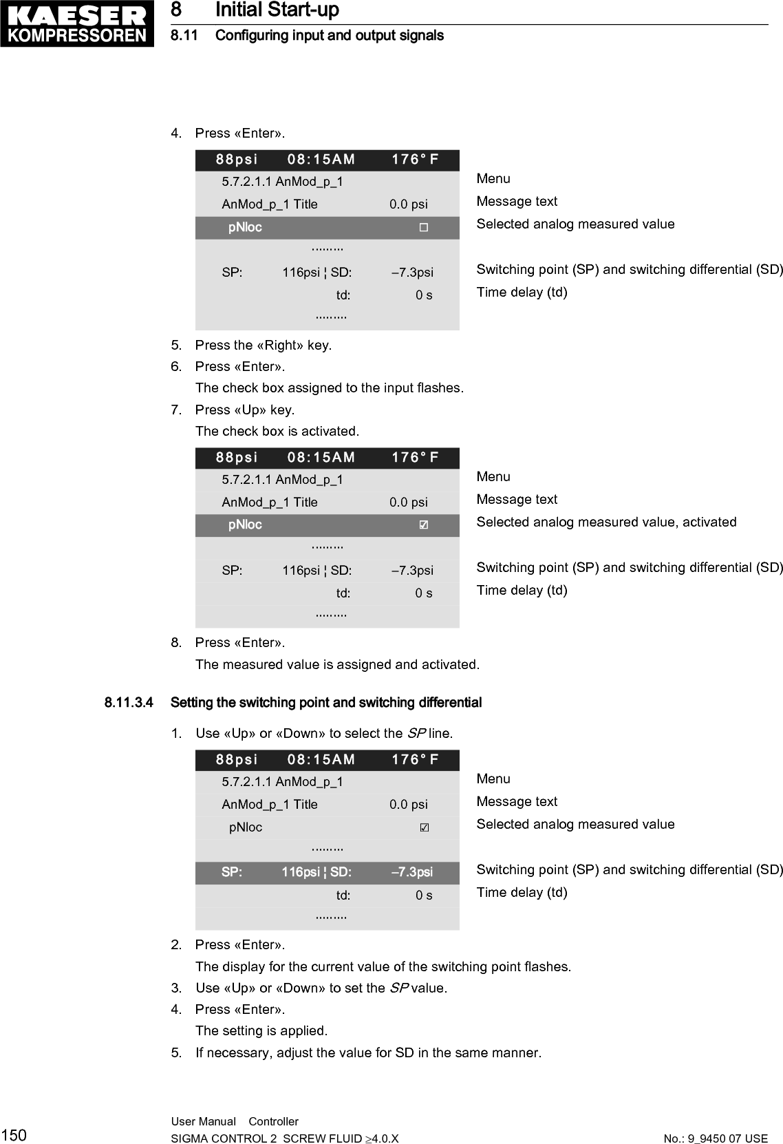
Prodrive Technologies
>
SC2MCSIO User Manual
Users Manual
Navigation menu
Upload a User Manual
Namespaces
Wiki Guide
HTML
PDF
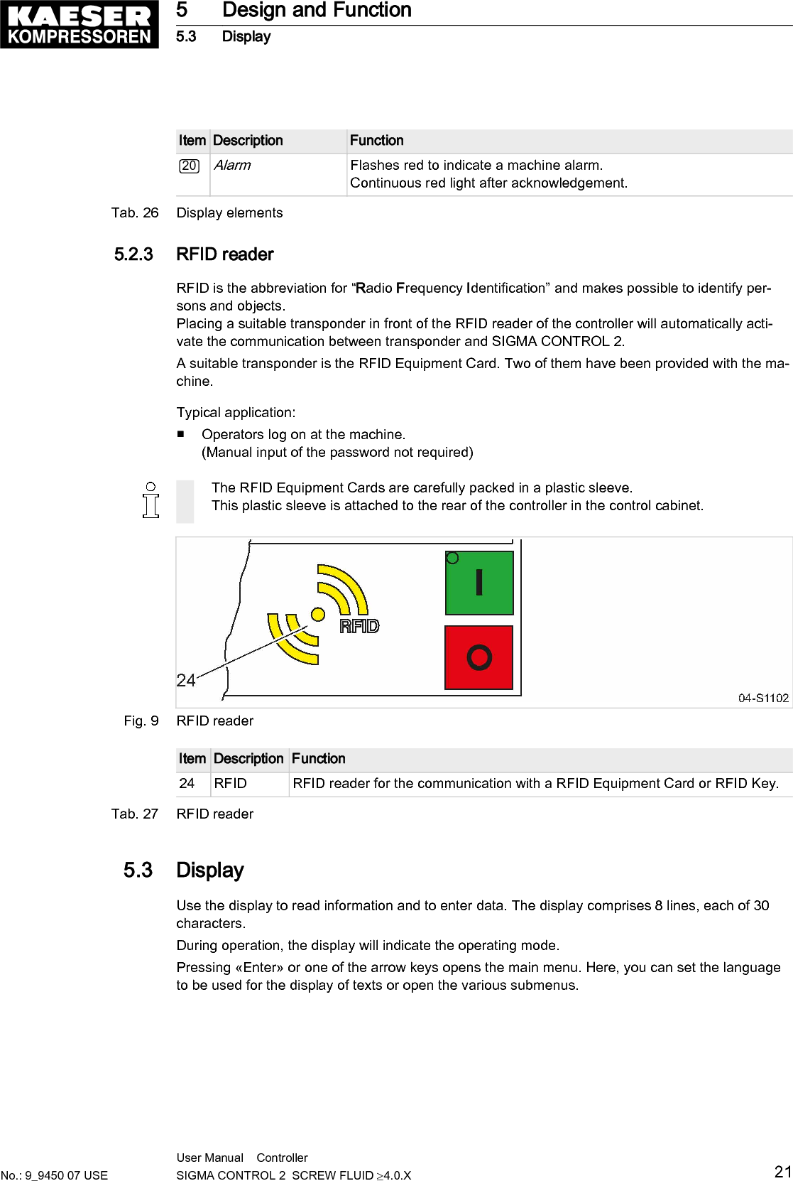
Info
Views
User Manual
Discussion / Help
Navigation

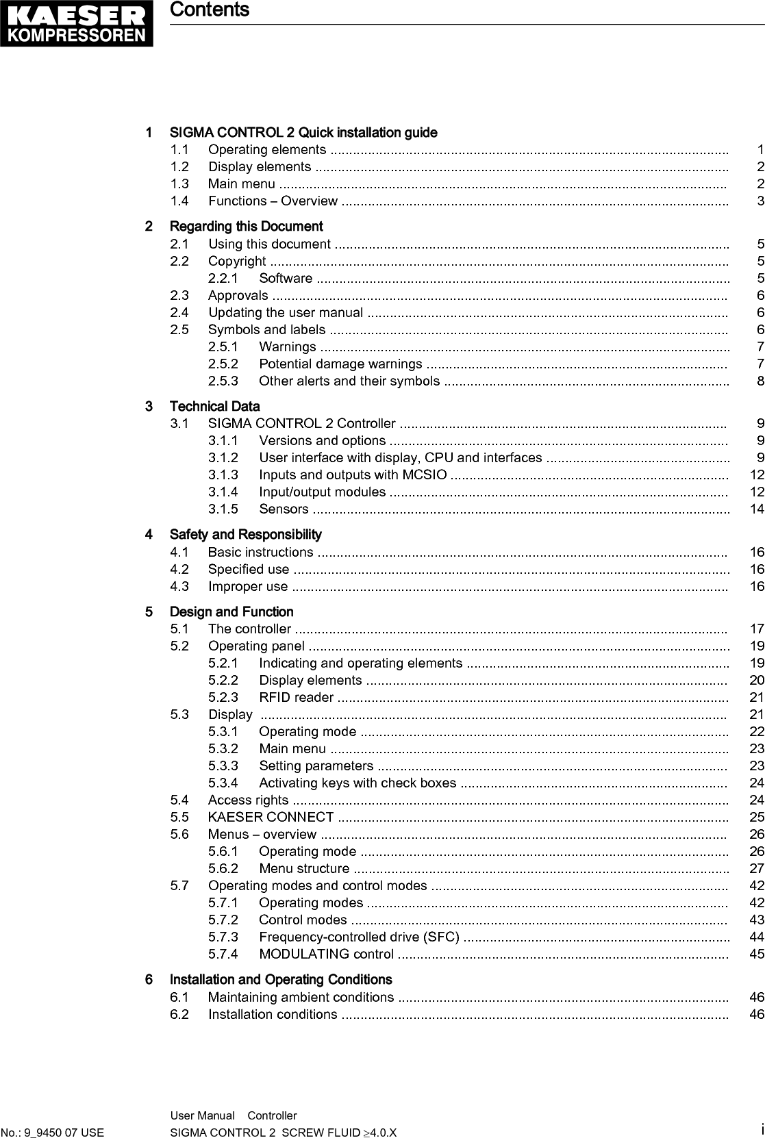
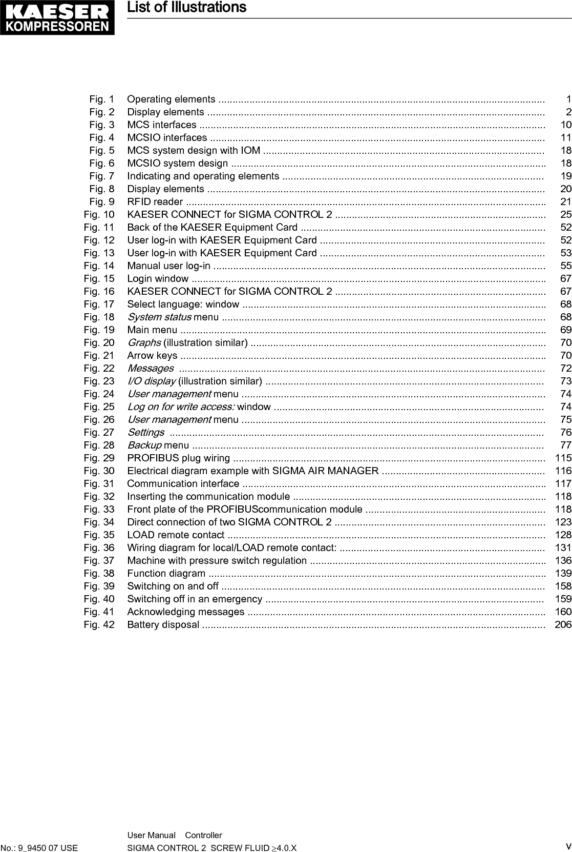

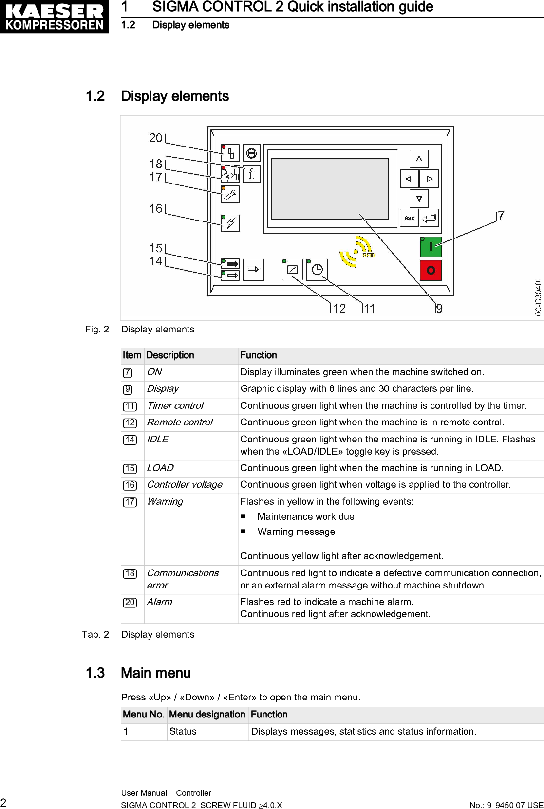


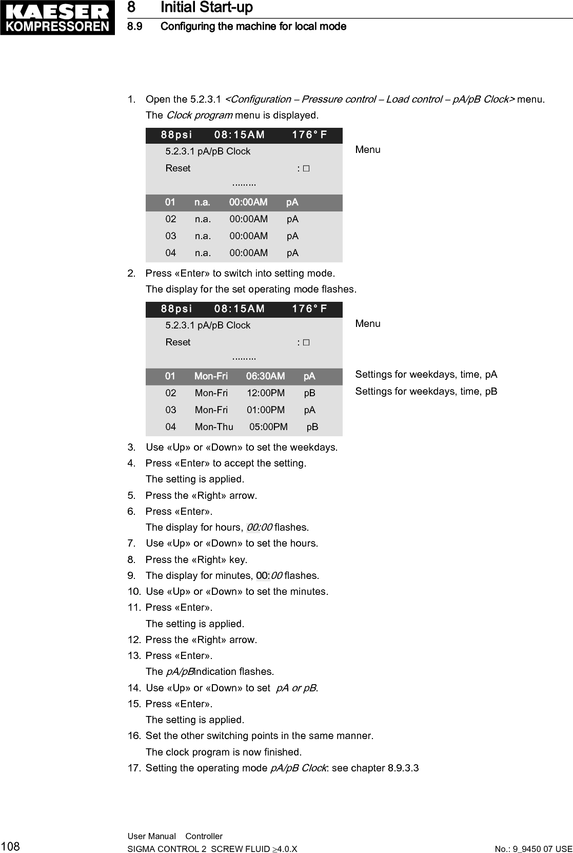
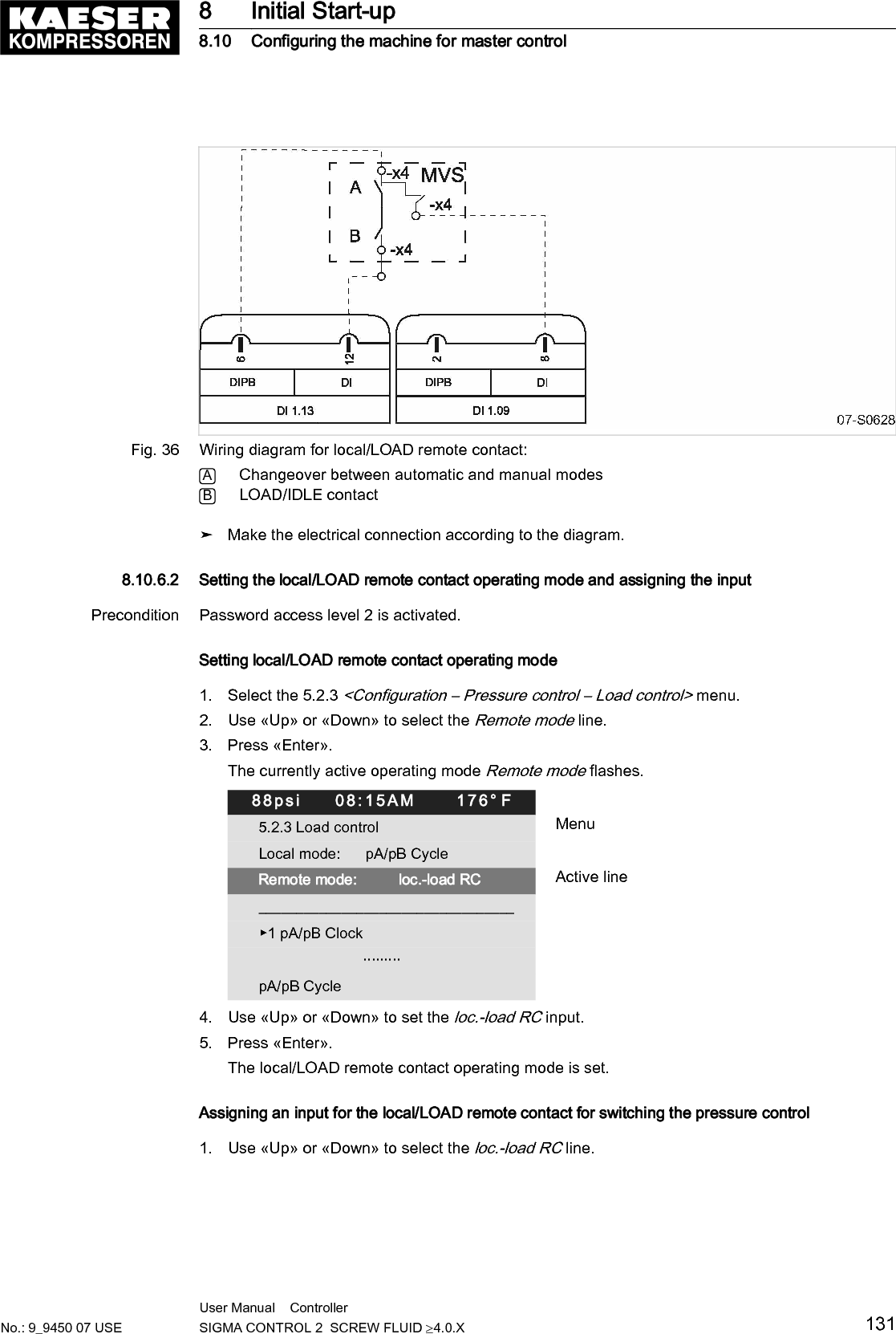
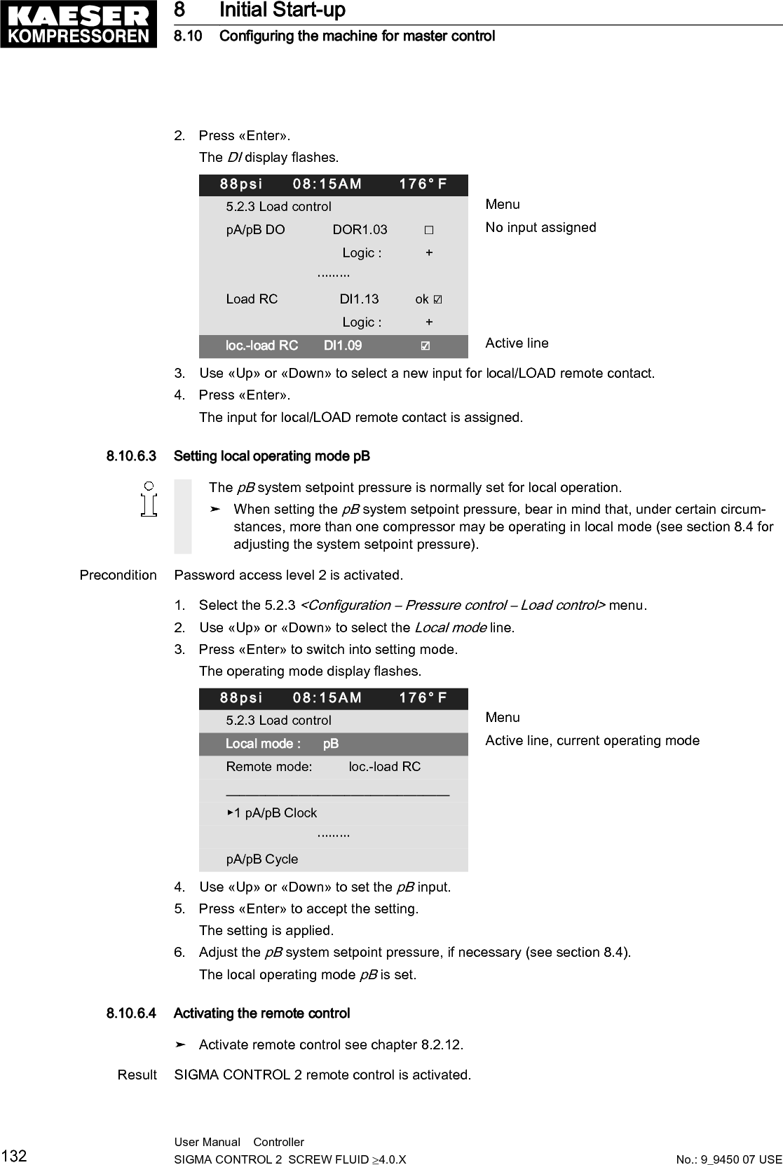
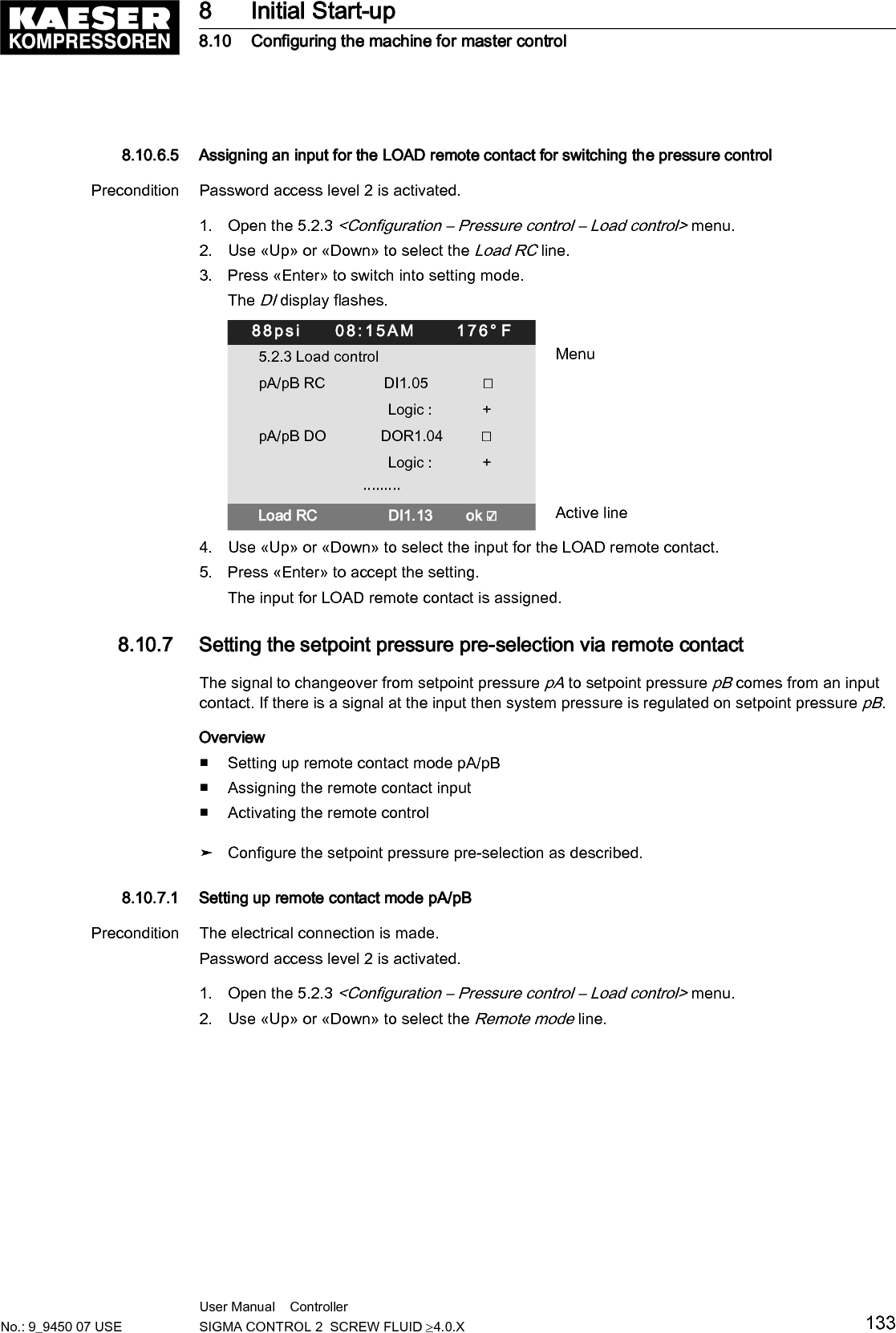
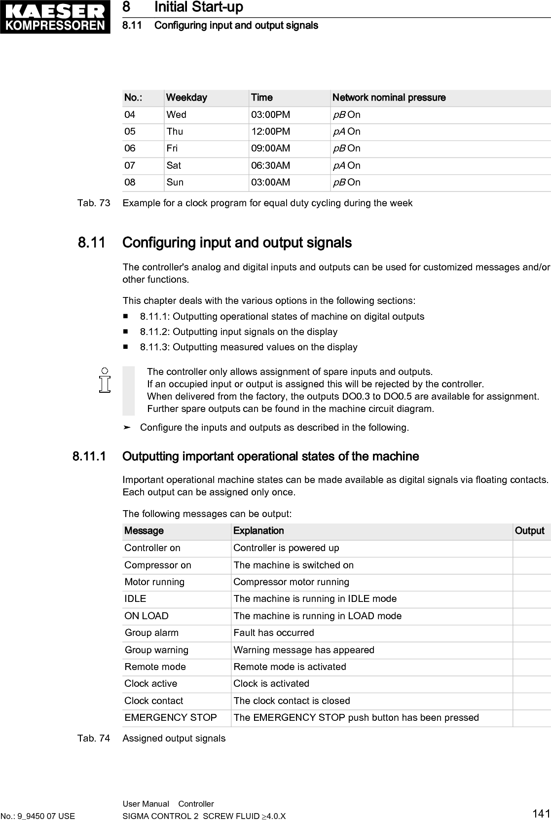
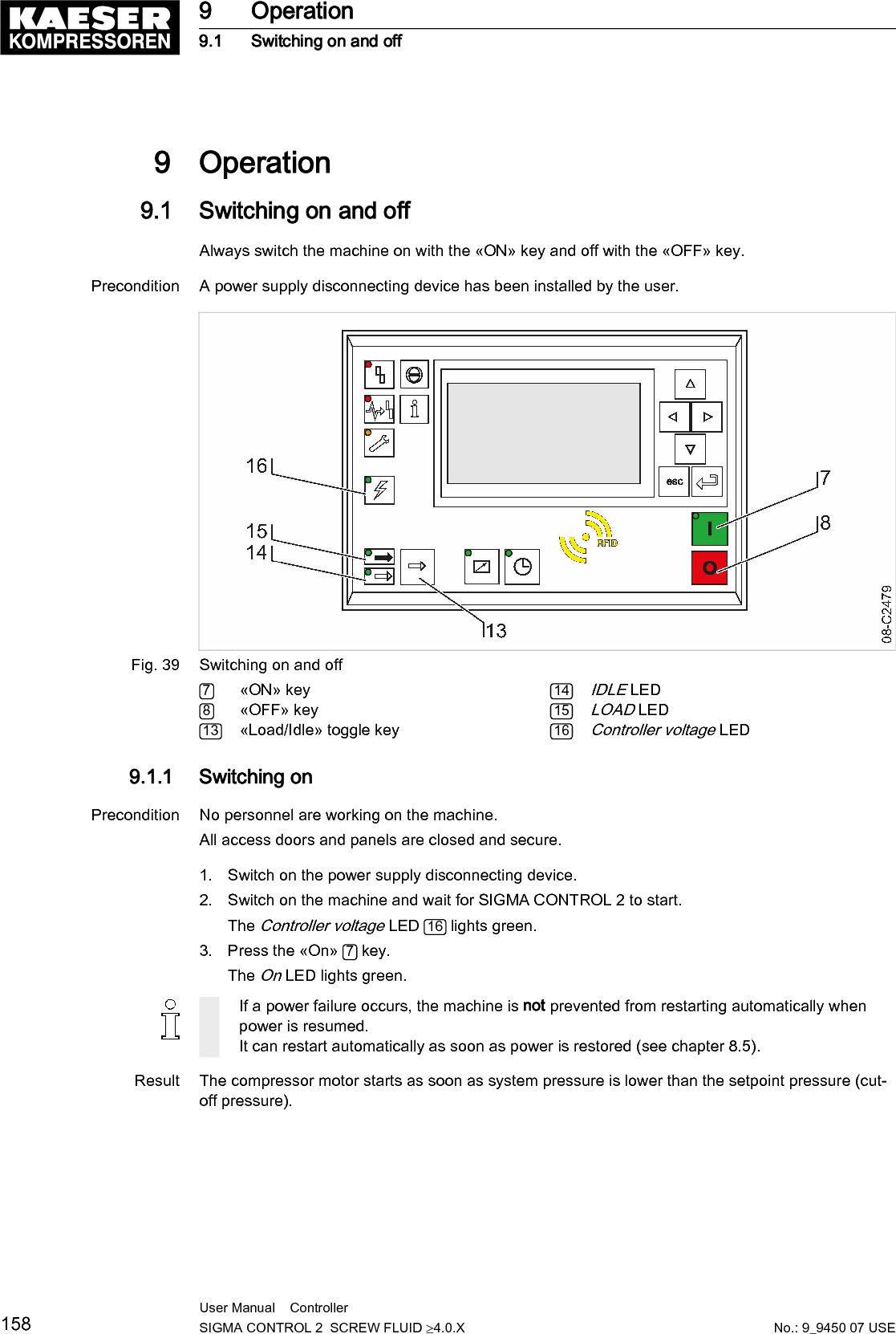
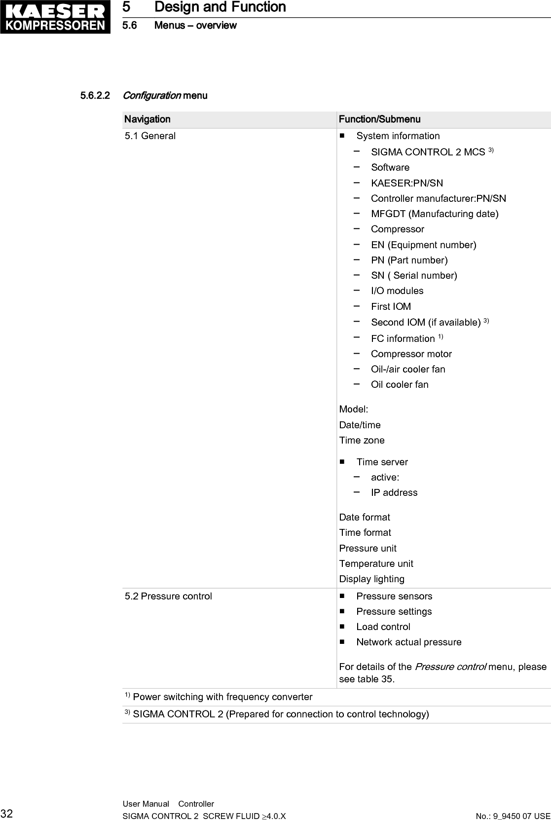
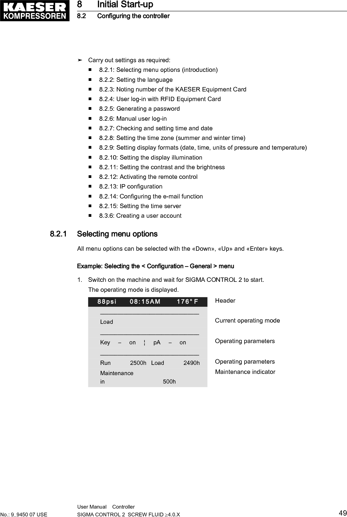
![3 Technical Data3.1 SIGMA CONTROL 2 ControllerIndustrial computer■ Internal temperature monitoring■ Internal low voltage monitoring■ Battery-buffered real-time clock─ Battery service span more than 10 years─ Battery replaceable3.1.1 Versions and optionsSIGMA CONTROL 2 is offered in different designs.Type Prepared for connection to control center Connection to control technology notprovidedOption C3 C48Compo‐nentsMain Control System (MCS): Slot for anoptional communication module (to con‐nect to a control center)Main Control System Input Output(MCSIO): Digital and analog inputs andoutputs integratedInput-Output-Module (IOM): Modules withdigital and analog inputs and outputs.Tab. 8 Versions and options3.1.2 User interface with display, CPU and interfacesUser interfaceFeature MCS MCSIOMaterial PlasticsWidth [in.] 7.5Height [in.] 5.1Depth [in.] 1.8 2.4Number of membrane keys 13Number of LEDs 9Degree of protection, control cabinet exterior IP 54Degree of protection, control cabinet interior IP 20Voltage [V] 24Current [A] 0.3 2.5Voltage source Input/output module ExternalTab. 9 User interface3 Technical Data3.1 SIGMA CONTROL 2 ControllerNo.: 9_9450 07 USEUser Manual Controller SIGMA CONTROL 2 SCREW FLUID ≥4.0.X 9](https://usermanual.wiki/Prodrive-Technologies/SC2MCSIO/User-Guide-3397040-Page-19.png)
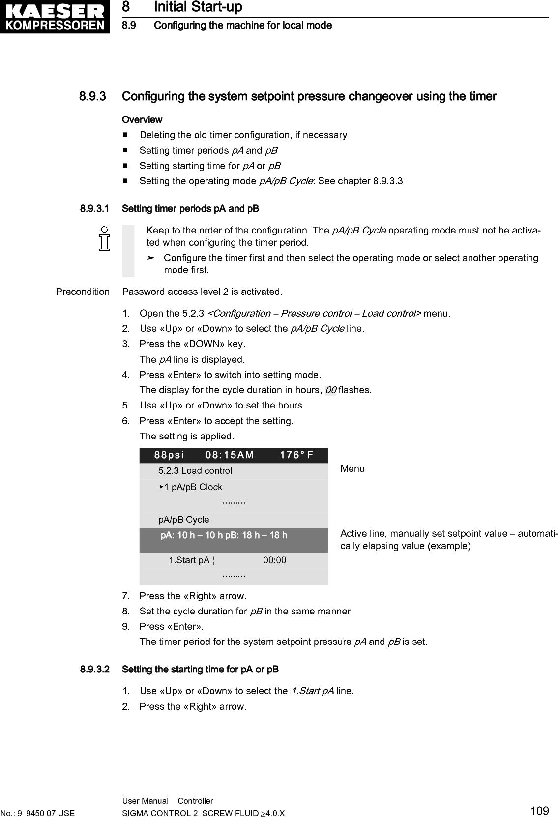
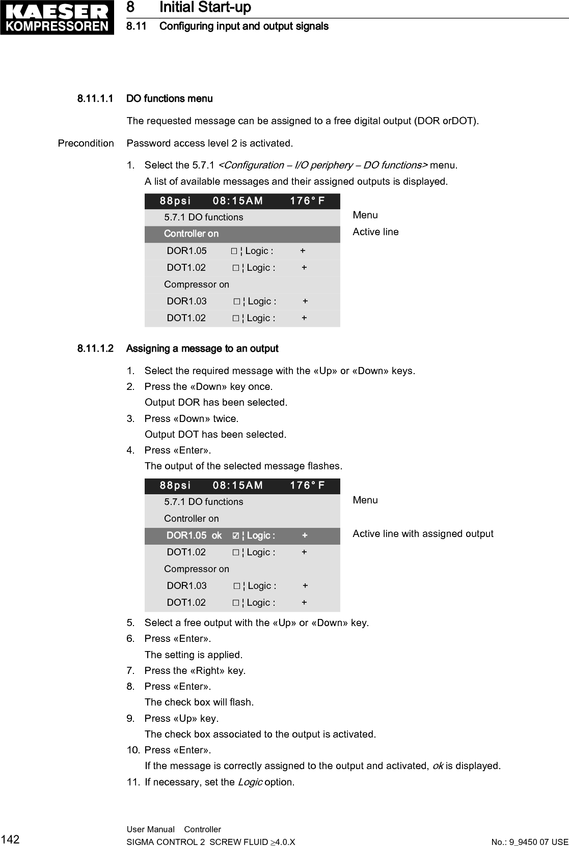
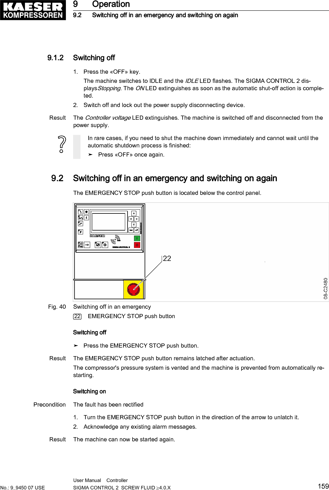
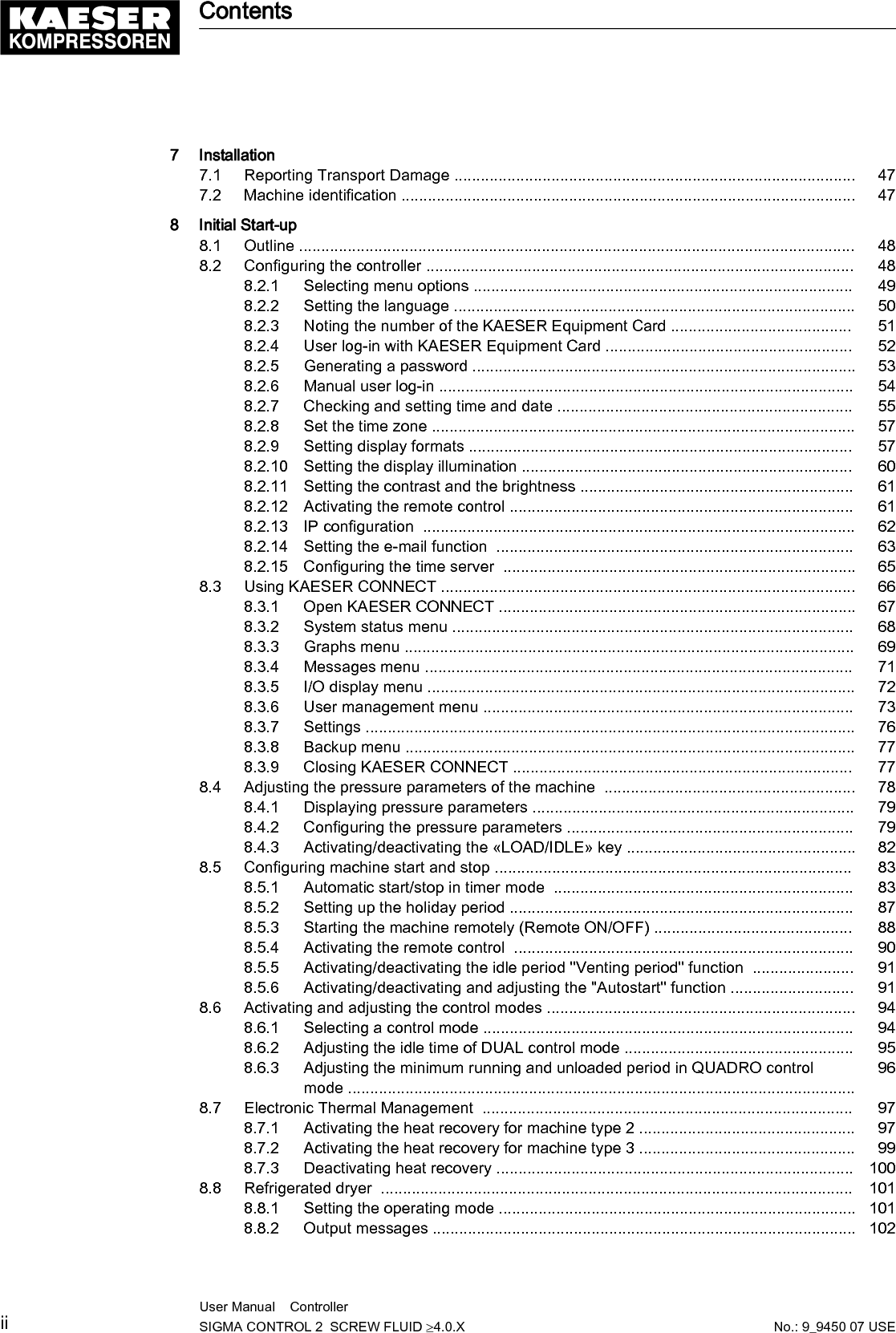
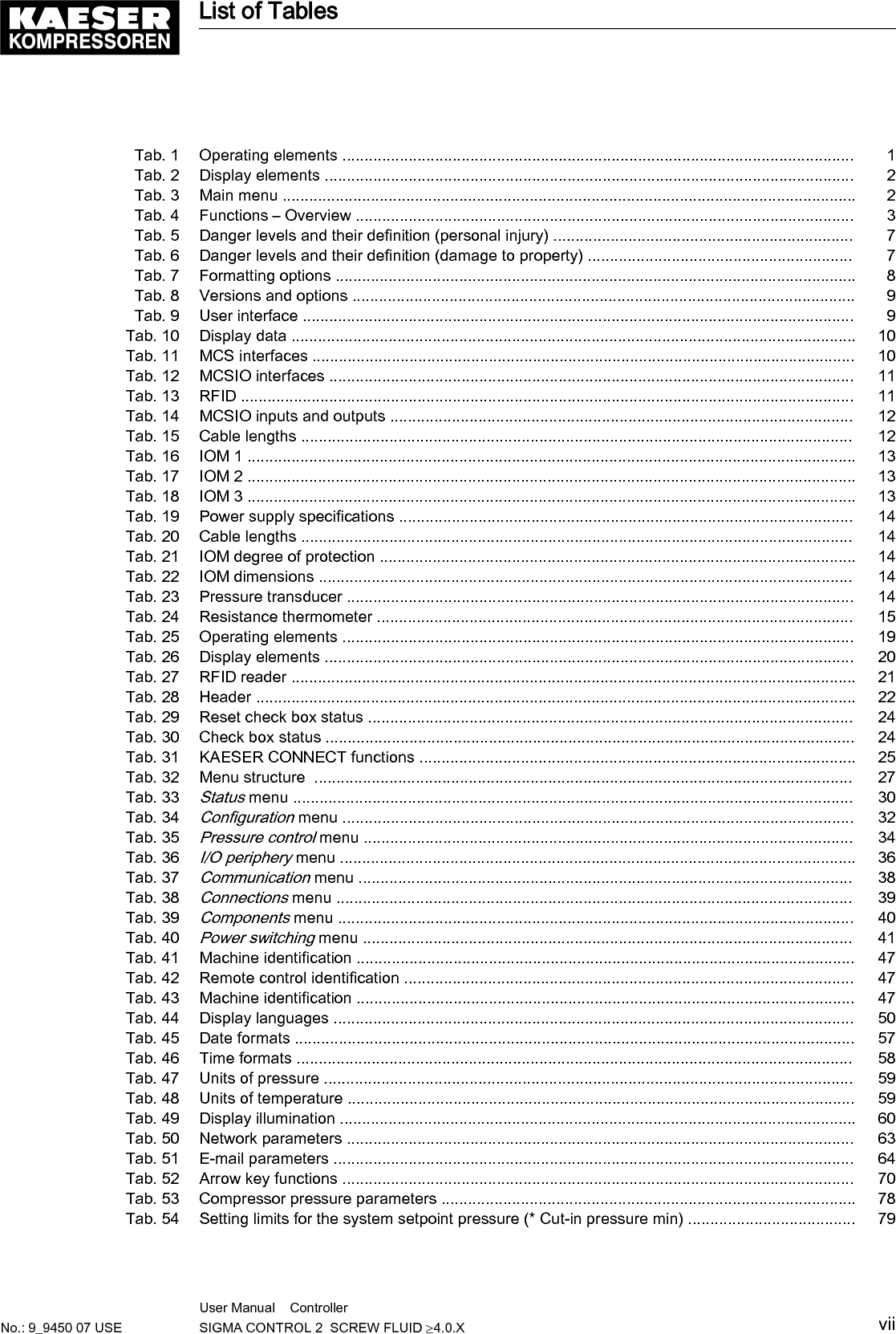
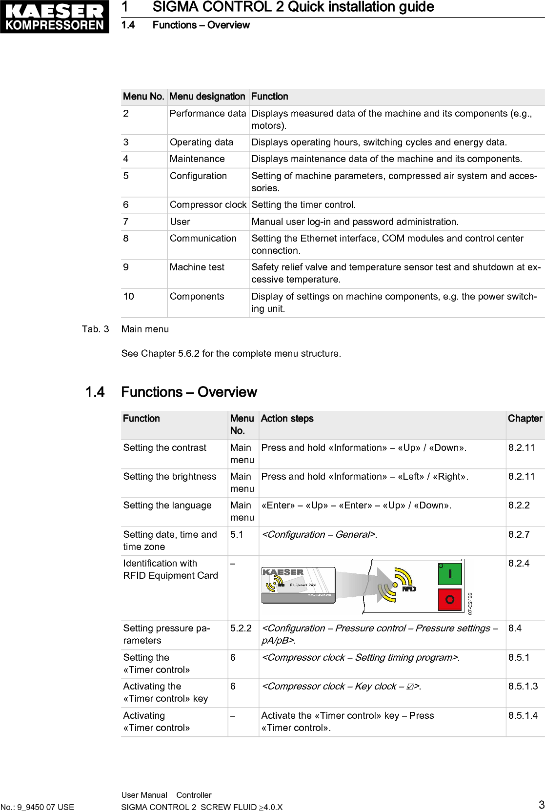
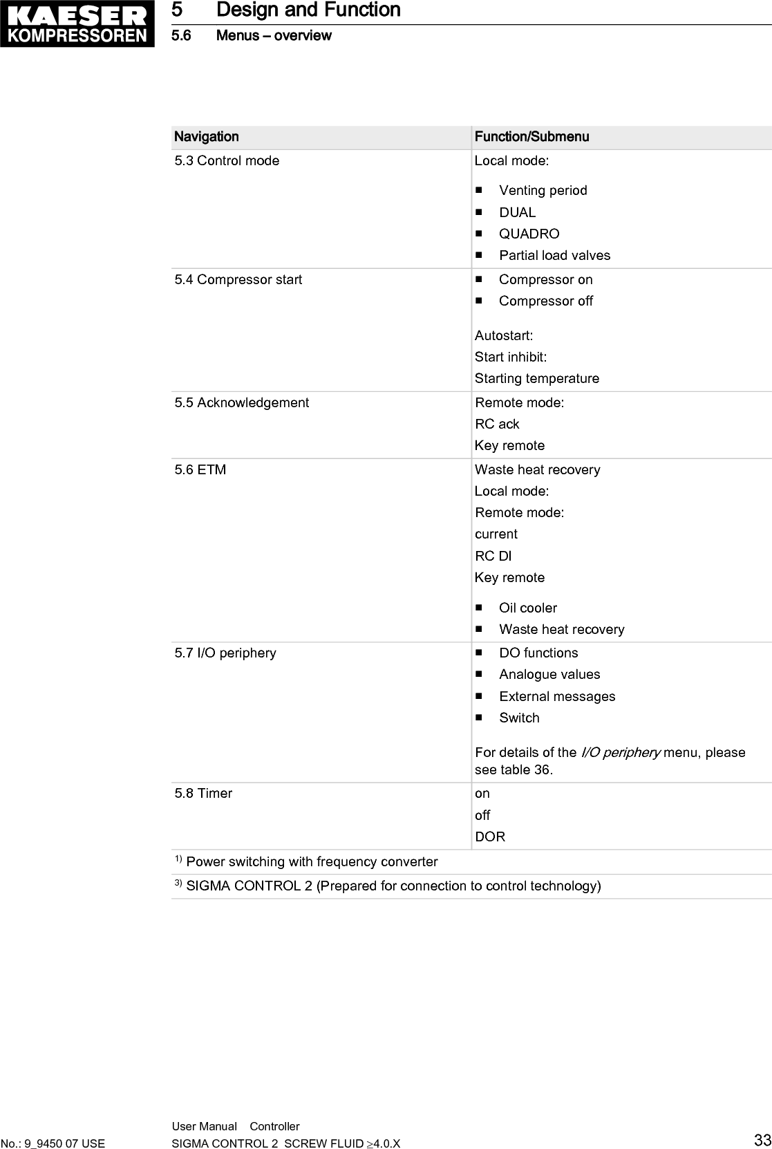
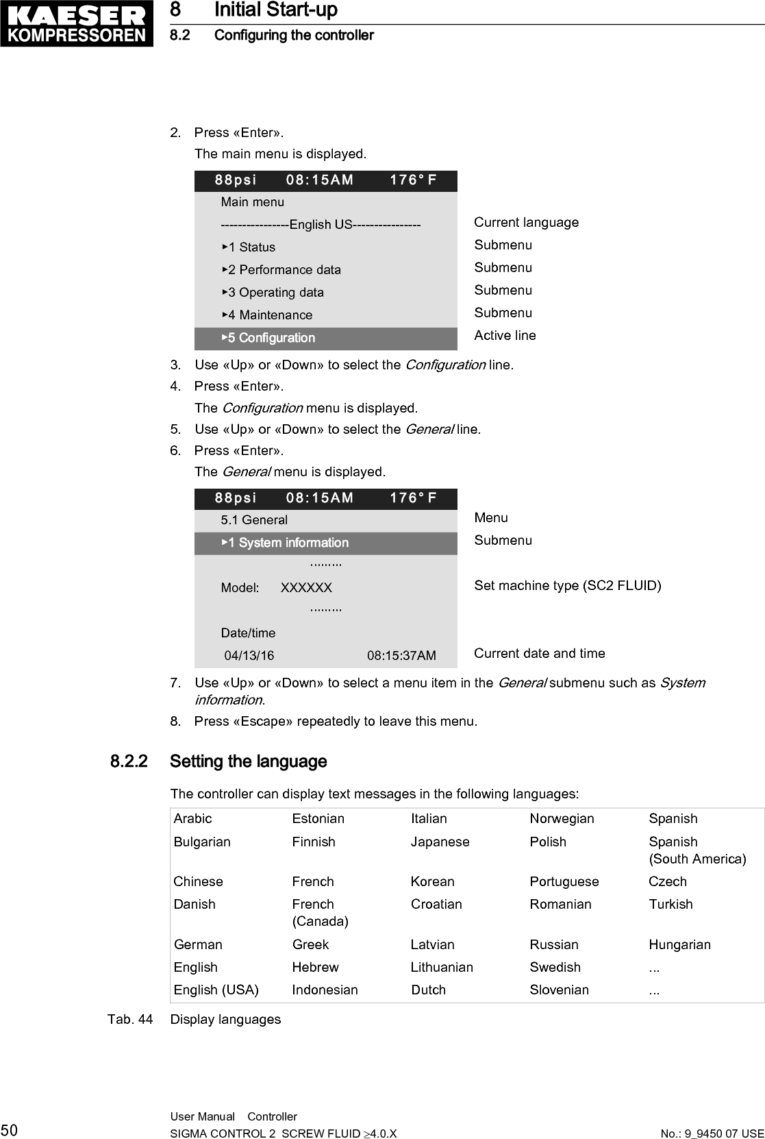
![DisplayFeature ValueGraphical display [px] 255 x 128Width [in.] 3.2Height [in.] 1.6Maximum number of lines/characters 8/30Colors Black/white with grey scaleLighting LED backlitpx = pixelTab. 10 Display dataFig. 3 MCS interfacesIdentification Interface ConnectionX1 Ethernet 10/100 Base T RJ 45 socketX2 I/O bus 9-pole SUB-D pinsX3 RS485–FC (USS interface) 9-pole SUB-D socketX4 Com modules,slot for communications moduleModule optional for:PROFIBUS, PROFINET,Modbus RTU, Modbus TCP,DeviceNetX5 SD card, SD card slot SD/SDHC cardX6 FG Functional ground (FG)The positions of the interfaces X1–X6 are marked on the rear of the controller.Tab. 11 MCS interfaces3 Technical Data3.1 SIGMA CONTROL 2 Controller10 User Manual Controller SIGMA CONTROL 2 SCREW FLUID ≥4.0.X No.: 9_9450 07 USE](https://usermanual.wiki/Prodrive-Technologies/SC2MCSIO/User-Guide-3397040-Page-20.png)
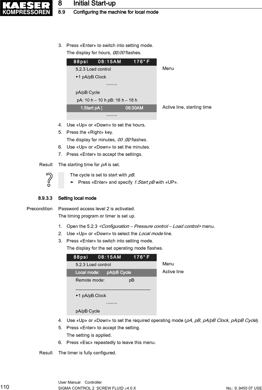
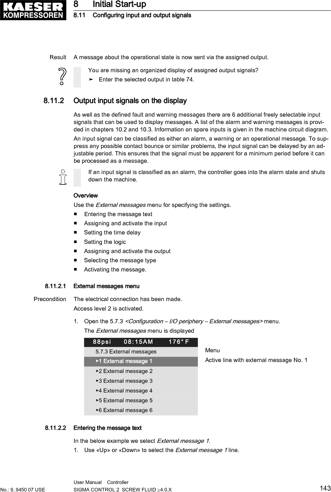
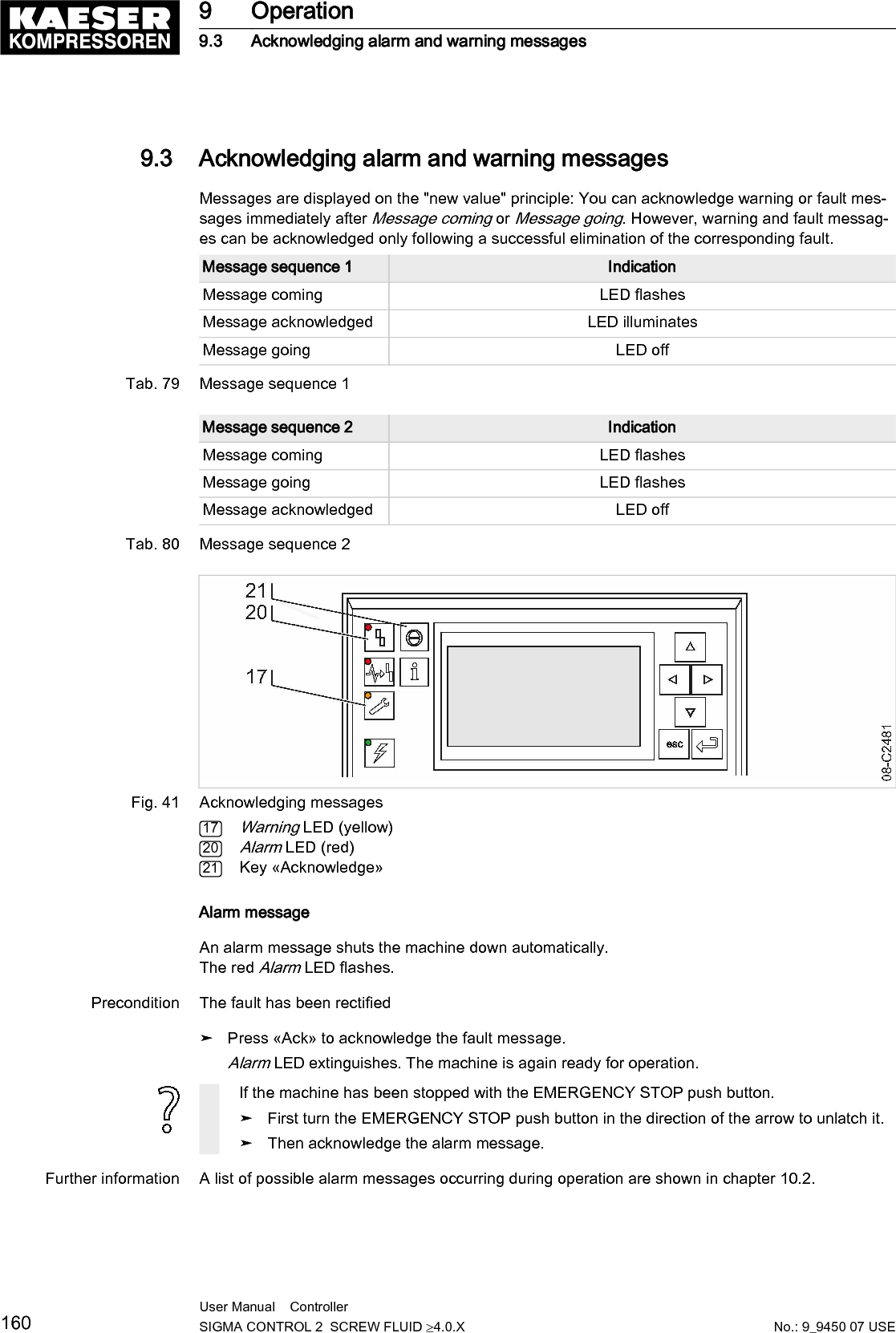
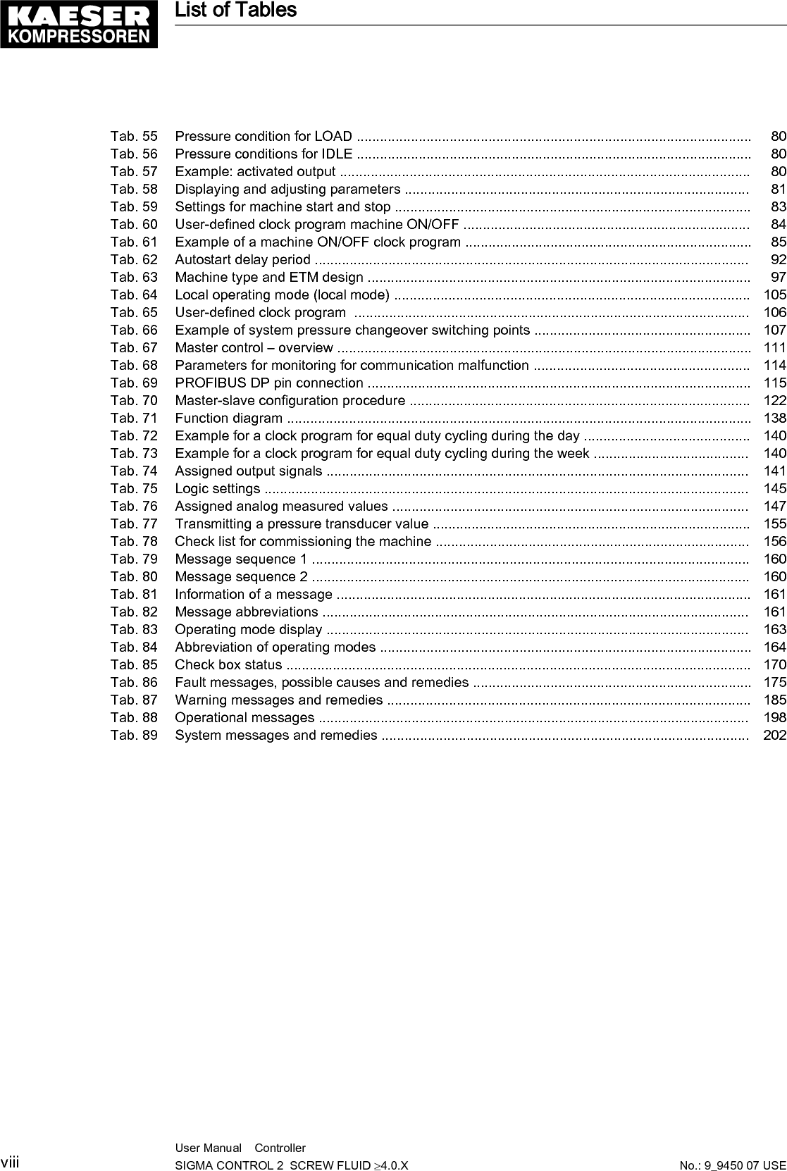
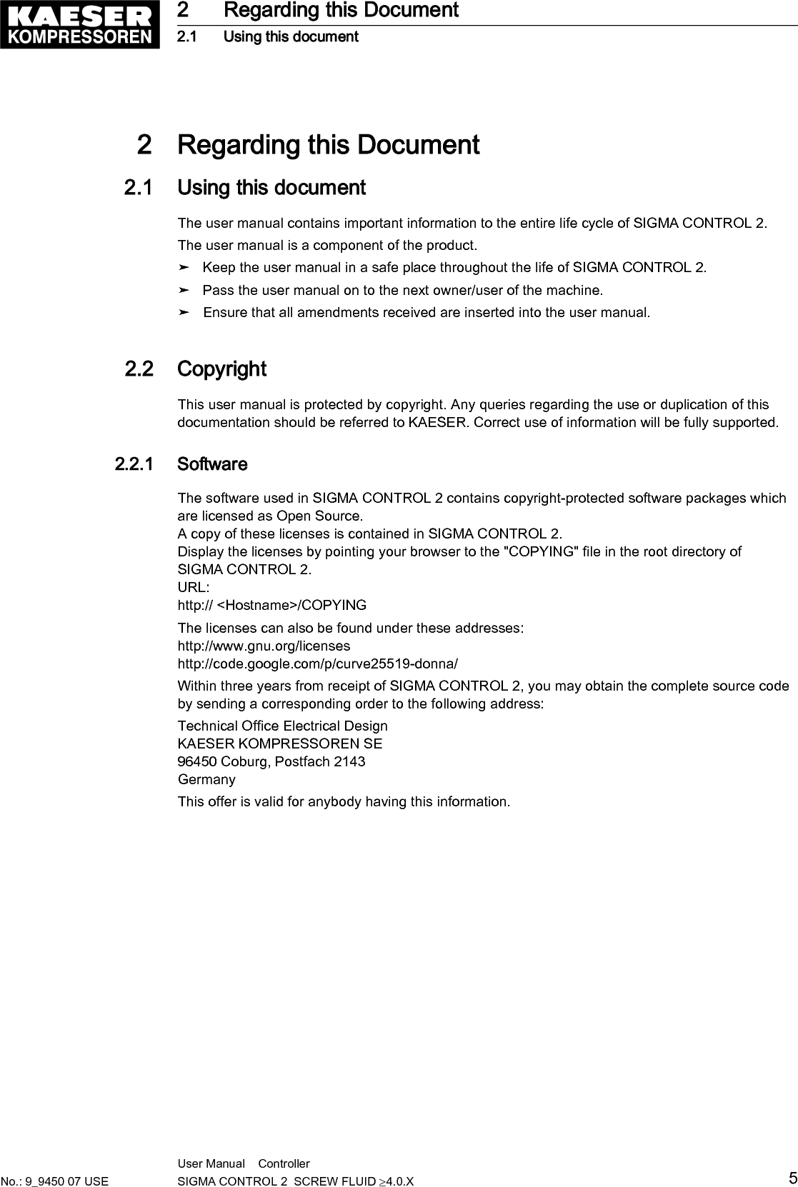
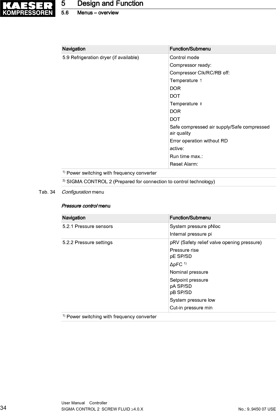
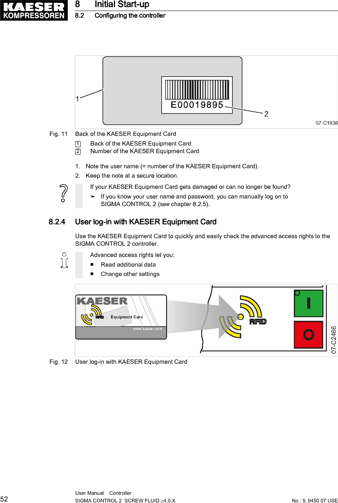
![Fig. 4 MCSIO interfacesMarking Interface ConnectionX1 Ethernet 10/100 Base T RJ 45 socketX3 RS485–FC (USS interface) 9-pole SUB-D socketX5 SD card, SD card slot SD/SDHC cardX6 FG Functional ground (FG)X7 24 VDC, DII Power supply 24 VDCDigital inputs DII1.00–DII1.05X8 DII/DOT Digital inputs DII1.06–DII1.07Digital outputs DOT1.00–DOT1.01X9 AII/AIR Analog input current 0–20 mA,AII1.00–AII1.01Analog input resistor AIR1.00–AIR1.01X10 DOR Digital output relay 250 VAC, 4 ADOR1.00–DOR1.04The positions of the interfaces X1–X10 are marked on the rear of the controller.Tab. 12 MCSIO interfacesIdentification with RFID Equipment CardFeature ValueHardware on the SIGMA CONTROL 2 controller RFID write/read deviceHardware (external) RFID Equipment CardRecognition distance [in.] Max. 23 Technical Data3.1 SIGMA CONTROL 2 ControllerNo.: 9_9450 07 USEUser Manual Controller SIGMA CONTROL 2 SCREW FLUID ≥4.0.X 11](https://usermanual.wiki/Prodrive-Technologies/SC2MCSIO/User-Guide-3397040-Page-21.png)
![Feature ValueFrequency [MHz] 13.56Tab. 13 RFID3.1.3 Inputs and outputs with MCSIOIntegrated inputs and outputs with MCSIO type controllerInput/Output NumberDigital input (DI), 24 VDC 8Digital output transistor (DOT), 24 VDC, 0.5 A 2Analog input current (AII), 0–20 mA 2Analog input resistor (AIR), PT100 2Digital output relay (DOR), 250 VAC, 4 A 5Tab. 14 MCSIO inputs and outputs3.1.3.1 Maximum cable lengthsInput/Output Cable length [ft.]Analog input current (AII),Analog input resistor (AIR)Analog output current (AOI)< 100Digital input (DI),Digital output relay (DOR)< 330Digital output transistor (DOT) < 100Tab. 15 Cable lengths3.1.4 Input/output modulesIOM modules only in combination with the MCS controller typeThere are three different types of input/output modules with different numbers of inputs and out‐puts.The number of input/output modules actually available depends on the machine type and the avail‐able options.Refer to the machine's wiring diagram for the input/output modules installed in your equipment.The input/output module features:■ Internal temperature monitoring■ Internal low voltage monitoring■ LED indication of operational status3 Technical Data3.1 SIGMA CONTROL 2 Controller12 User Manual Controller SIGMA CONTROL 2 SCREW FLUID ≥4.0.X No.: 9_9450 07 USE](https://usermanual.wiki/Prodrive-Technologies/SC2MCSIO/User-Guide-3397040-Page-22.png)
![3.1.4.1 Electrical connection specifications IOMPower is provided by the power supply unit within the machine.Feature ValueRated power supply (stabilized) [V DC] 24Current consump‐tion SIGMA CONTROL 2 with IOM 1 [A]2.4Current consumption IOM 2 [A] 2.5Current consumption IOM 3 [A] 1.6IOM = Input/Output moduleTab. 19 Power supply specifications3.1.4.2 Maximum cable lengthsInput/Output Conductor length [ft.]Analog input current (AII),Analog input resistor (AIR)Analog output current (AOI)< 100Digital input (DI),Digital output relay (DOR)< 330Digital output transistor (DOT) < 100Tab. 20 Cable lengths3.1.4.3 Input/output module – degree of protectionFeature ValueDegree of protection within the machine IP 54Degree of protection within the control cabinet IP 20Tab. 21 IOM degree of protection3.1.4.4 Input/output modules – dimensionsFeature ValueWidth [in.] 4.9Height [in.] 9.8Depth [in.] 1.7Tab. 22 IOM dimensions3.1.5 SensorsPressure transducerFeature ValueOutput signal [mA] 0/4–203 Technical Data3.1 SIGMA CONTROL 2 Controller14 User Manual Controller SIGMA CONTROL 2 SCREW FLUID ≥4.0.X No.: 9_9450 07 USE](https://usermanual.wiki/Prodrive-Technologies/SC2MCSIO/User-Guide-3397040-Page-24.png)


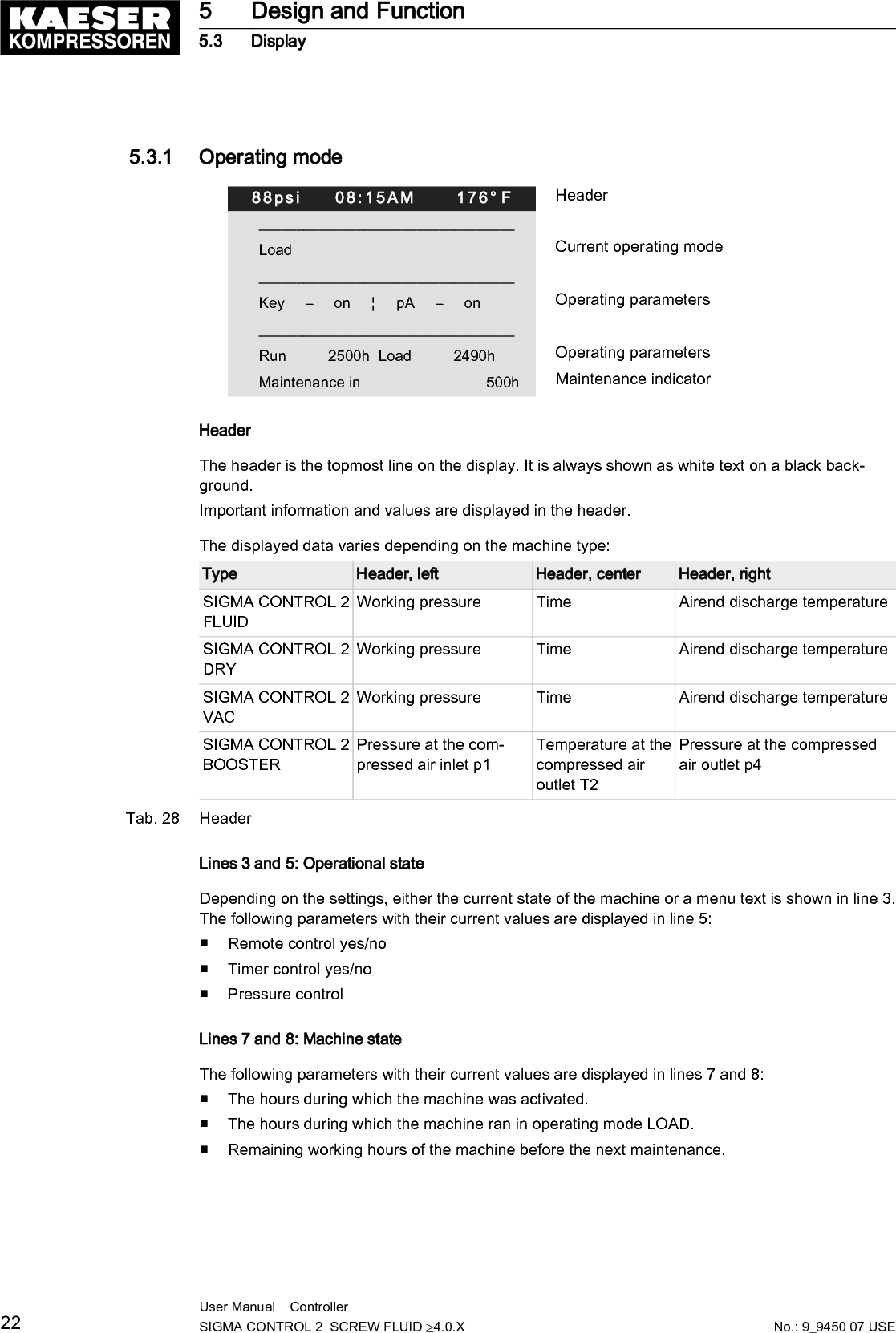


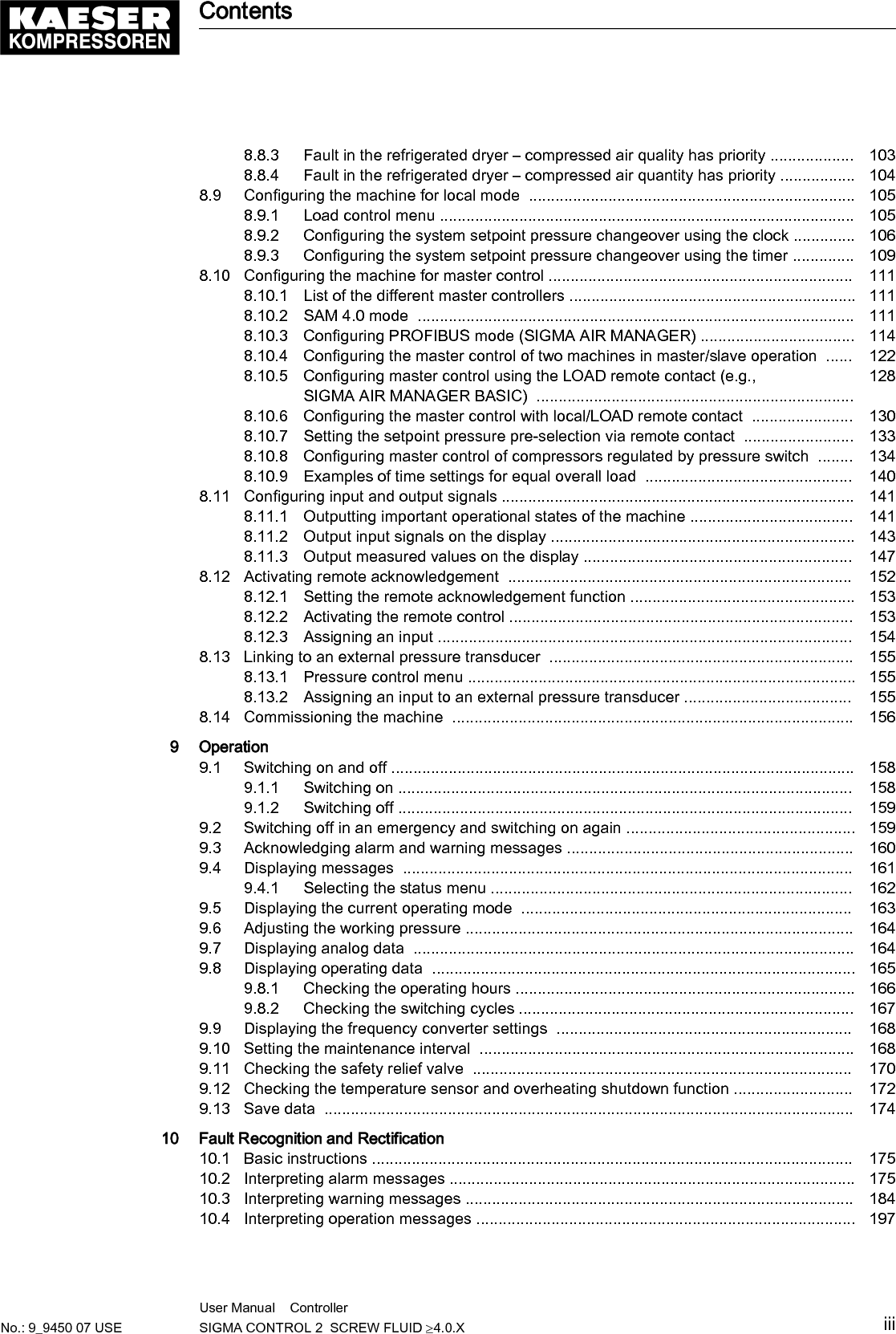
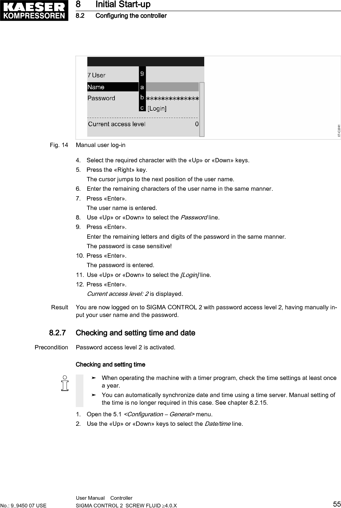
![Fig. 14 Manual user log-in4. Select the required character with the «Up» or «Down» keys.5. Press the «Right» key.The cursor jumps to the next position of the user name.6. Enter the remaining characters of the user name in the same manner.7. Press «Enter».The user name is entered.8. Use «Up» or «Down» to select the Password line.9. Press «Enter».Enter the remaining letters and digits of the password in the same manner.The password is case sensitive!10. Press «Enter».The password is entered.11. Use «Up» or «Down» to select the [Login] line.12. Press «Enter».Current access level: 2 is displayed.Result You are now logged on to SIGMA CONTROL 2 with password access level 2, having manually in‐put your user name and the password.8.2.7 Checking and setting time and datePrecondition Password access level 2 is activated.Checking and setting time➤ When operating the machine with a timer program, check the time settings at least oncea year.➤ You can automatically synchronize date and time using a time server. Manual setting ofthe time is no longer required in this case. See chapter 8.2.15.1. Open the 5.1 <Configuration – General> menu.2. Use the «Up» or «Down» keys to select the Date/time line.8 Initial Start-up8.2 Configuring the controllerNo.: 9_9450 07 USEUser Manual Controller SIGMA CONTROL 2 SCREW FLUID ≥4.0.X 55](https://usermanual.wiki/Prodrive-Technologies/SC2MCSIO/User-Guide-3397040-Page-65.png)
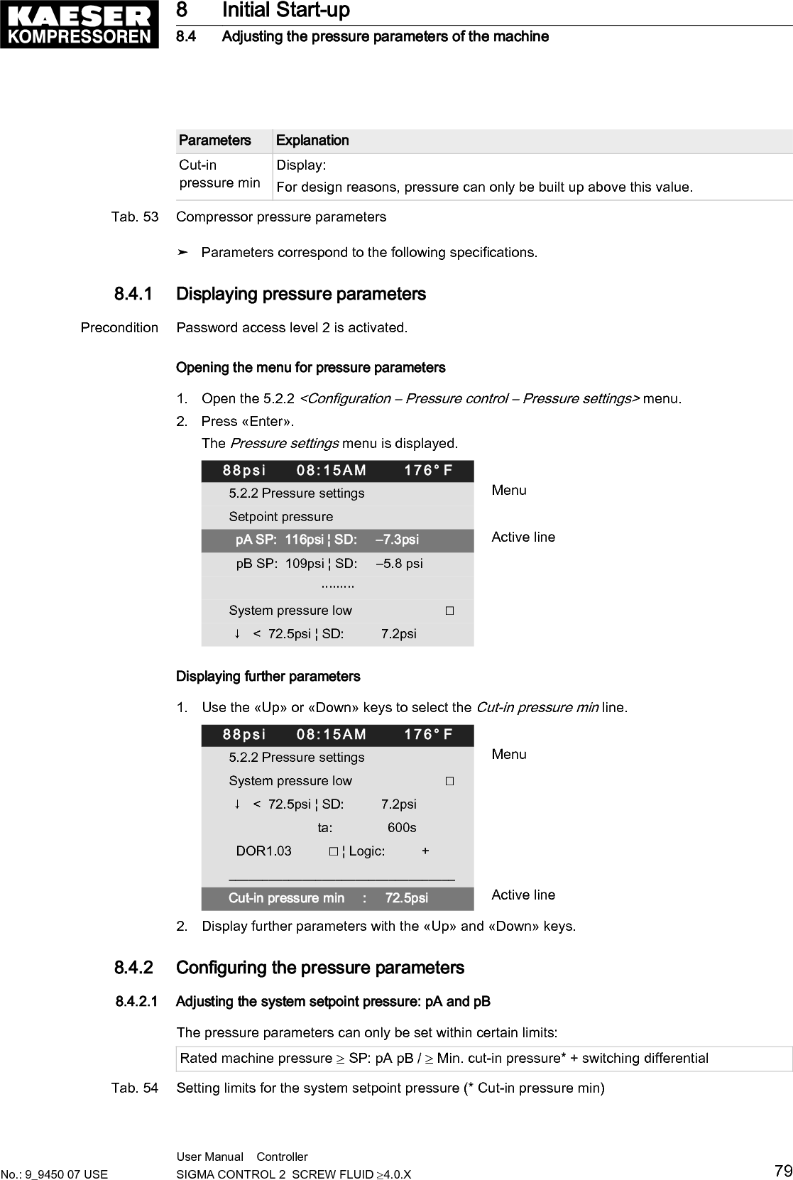
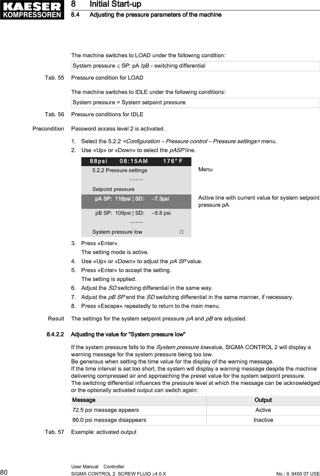
![8.4 Adjusting the pressure parameters of the machineThis section contains instructions for how to display and adjust the pressure parameters of the ma‐chine.The section is divided into the following sections:■ 8.4.1: Displaying pressure parameters■ 8.4.2: Configuring the pressure parameters"Display" means that the parameter will only be shown."Setting" means that the parameter can also be changed.Parameters ExplanationpRV Display:Activating pressure of the safety relief valve on the oil separator tank.pE Pressure increase.Setting:■ pE SP: Switching point for pressure increase; upper safety limit for machinemaximum pressure; in an external LOAD control, this value is used to switchthe machine from LOAD to IDLE in the event of a fault.■ pE SD: Switching differential of pressure increase.ΔpFC Limiting value for machines with frequency-controlled drive (SFC).Setting:■ dp FC: Limit of the lowest delivery quantity. When the value [switching pointsystem setpoint pressure +dp FC] is exceeded, the compressor switches fromLOAD to IDLE.NominalpressureDisplay:The compressor is designed for this pressure (maximum system pressure set‐point).SetpointpressureSetpoint pressure can be regulated to two values: pA and pB.Setting:■ Switching point pA or control pressure pA in machines with frequency convert‐er (SFC).■ Switching point pB or control pressure pB in machines with frequency convert‐er (SFC).Systempressure lowA warning message is displayed when the limit value for the system pressure isreached.Setting:■ SD: Switching differential for system pressure low.↓: Switching point for system pressure low.■ Option: Configure the output signal.Warning message displayed or an additional output signal is sent, e.g., to acontrol center.8 Initial Start-up8.4 Adjusting the pressure parameters of the machine78 User Manual Controller SIGMA CONTROL 2 SCREW FLUID ≥4.0.X No.: 9_9450 07 USE](https://usermanual.wiki/Prodrive-Technologies/SC2MCSIO/User-Guide-3397040-Page-88.png)
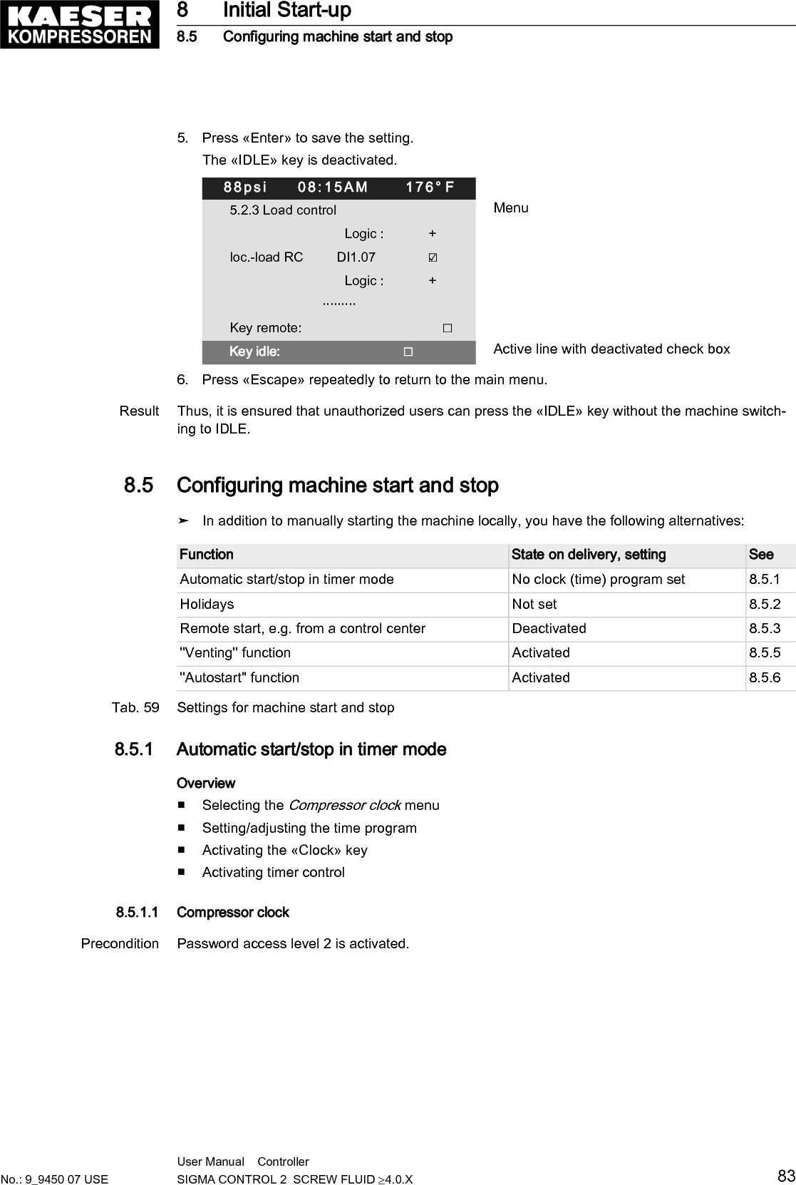
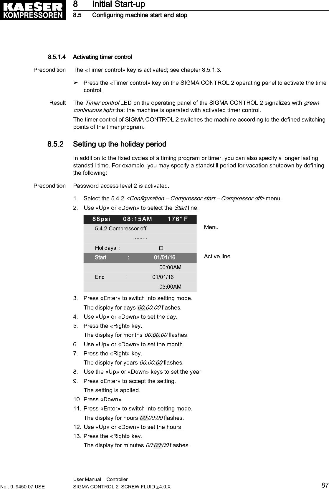
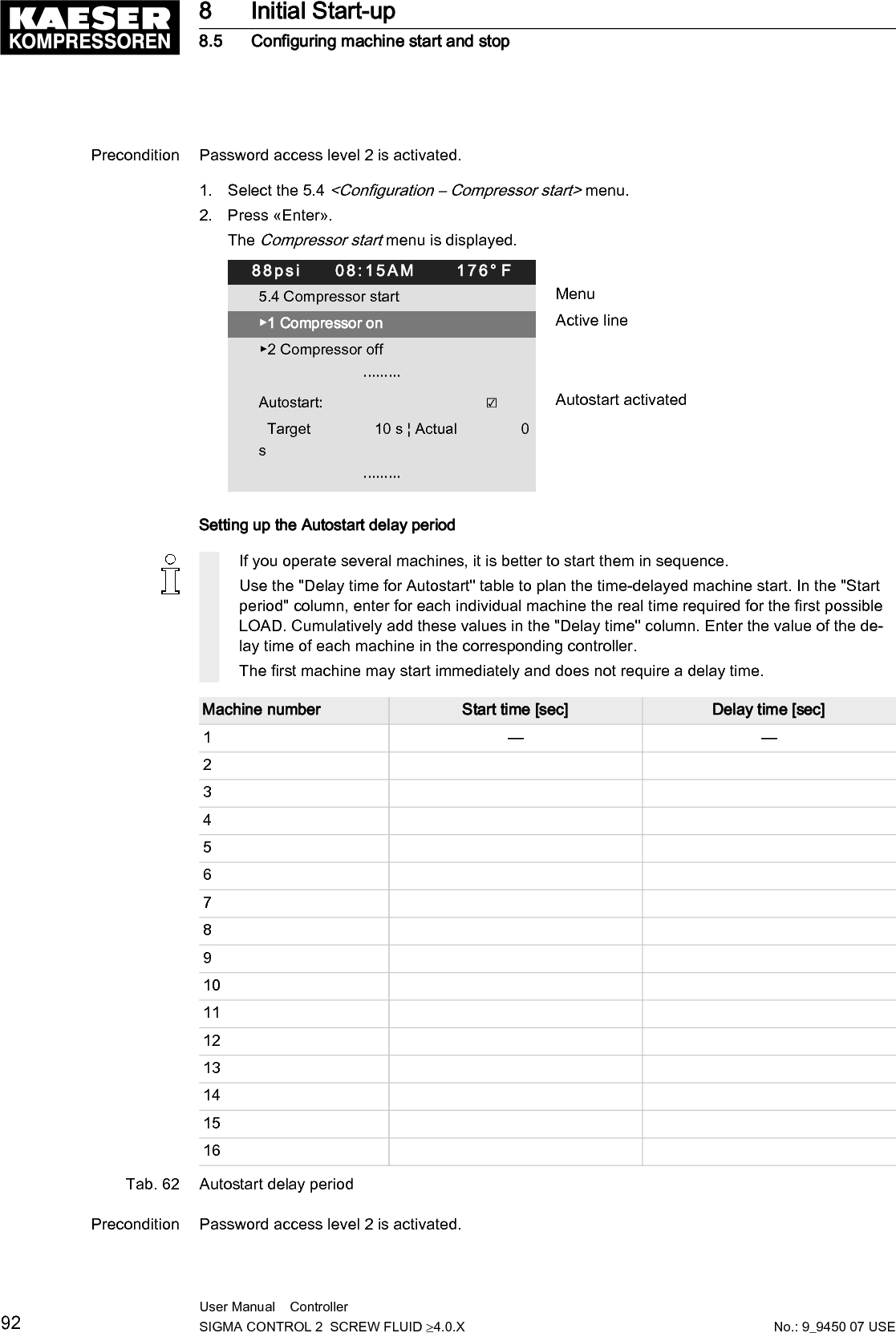
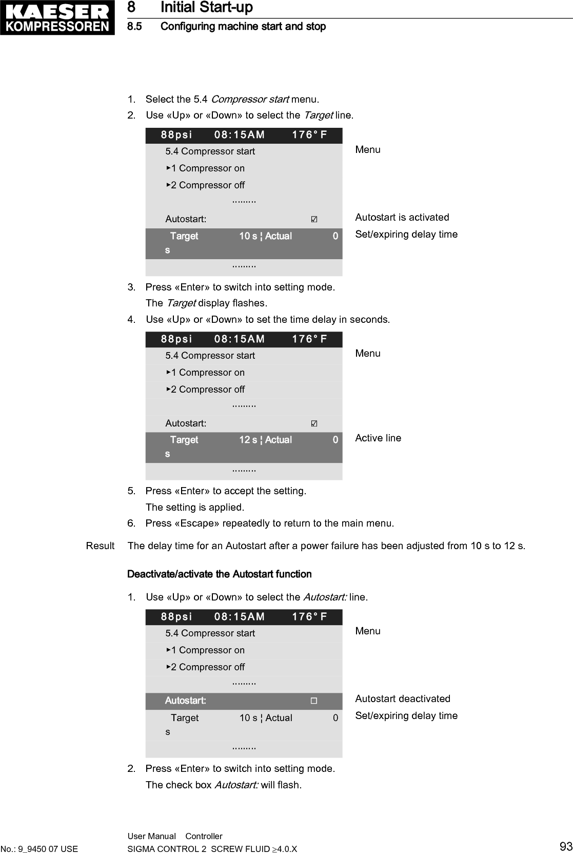
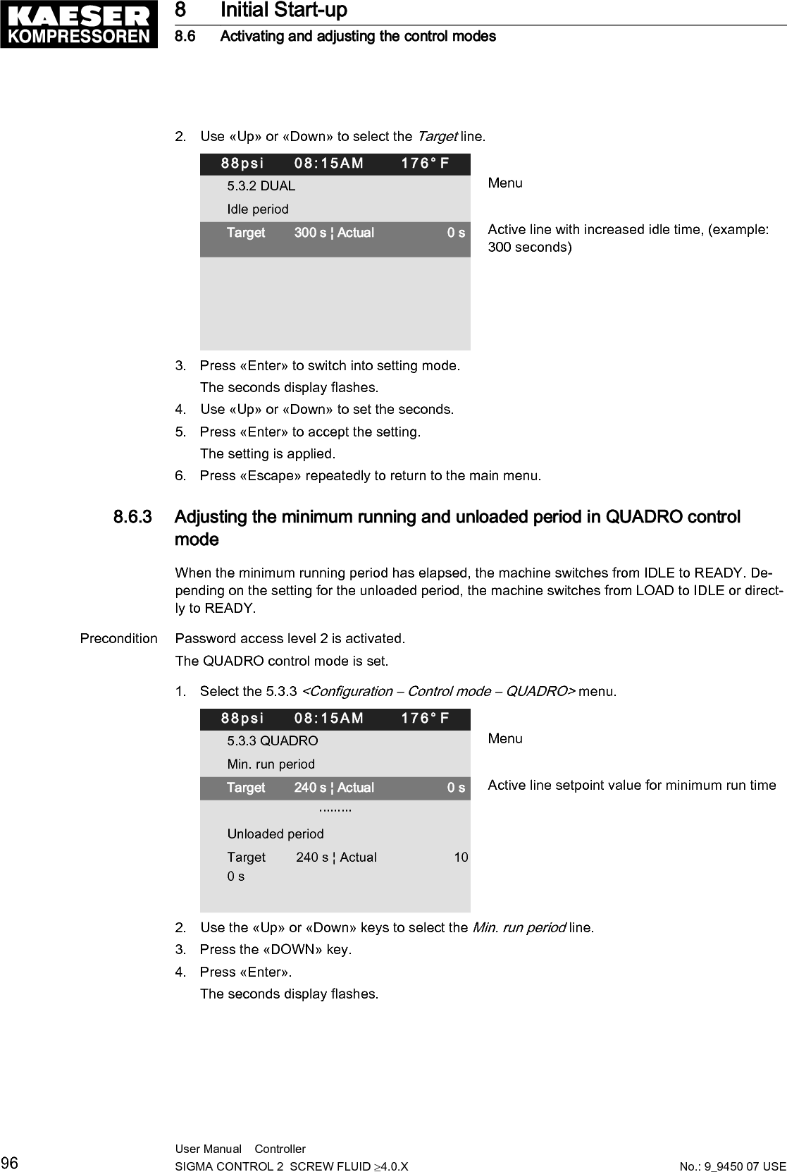
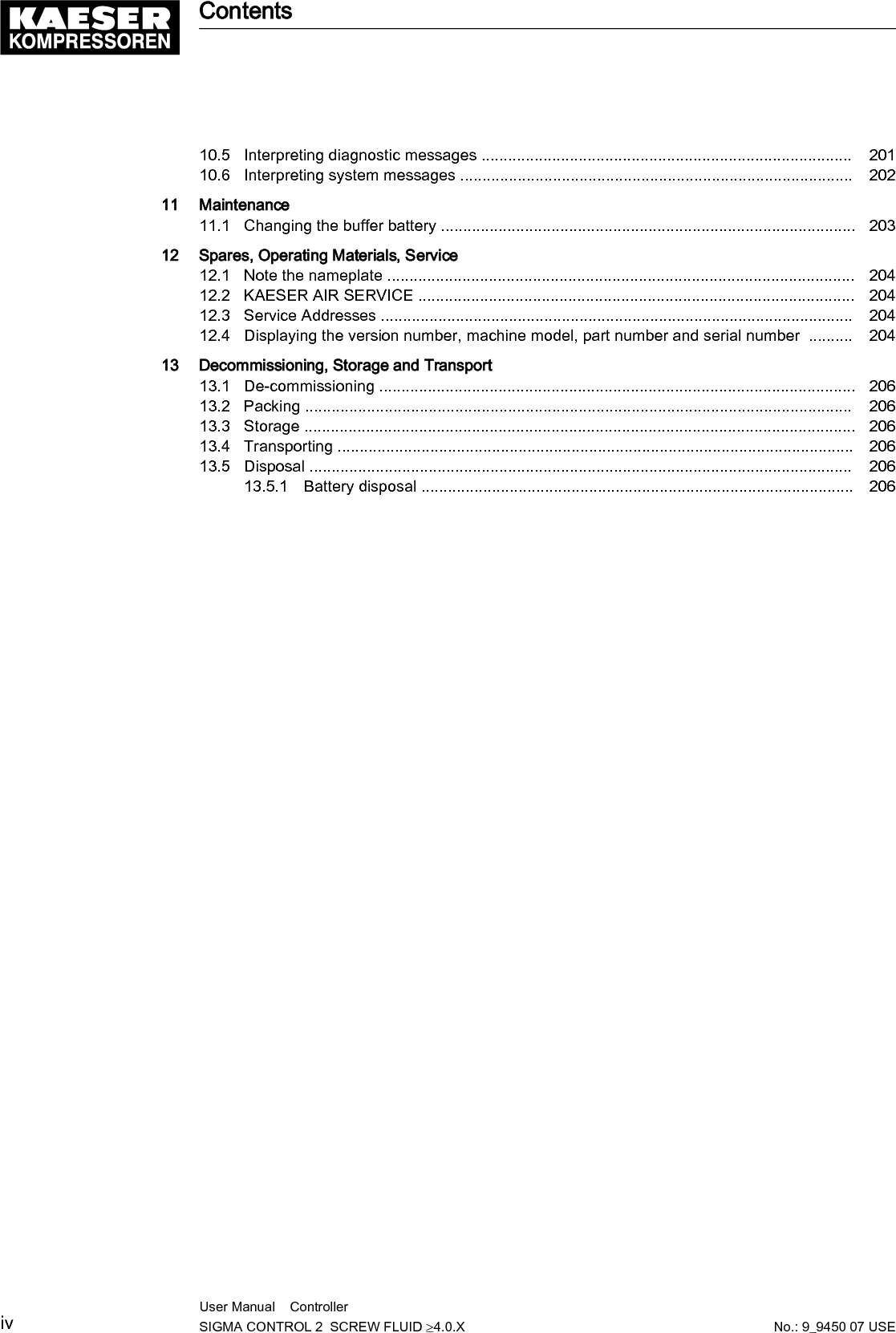
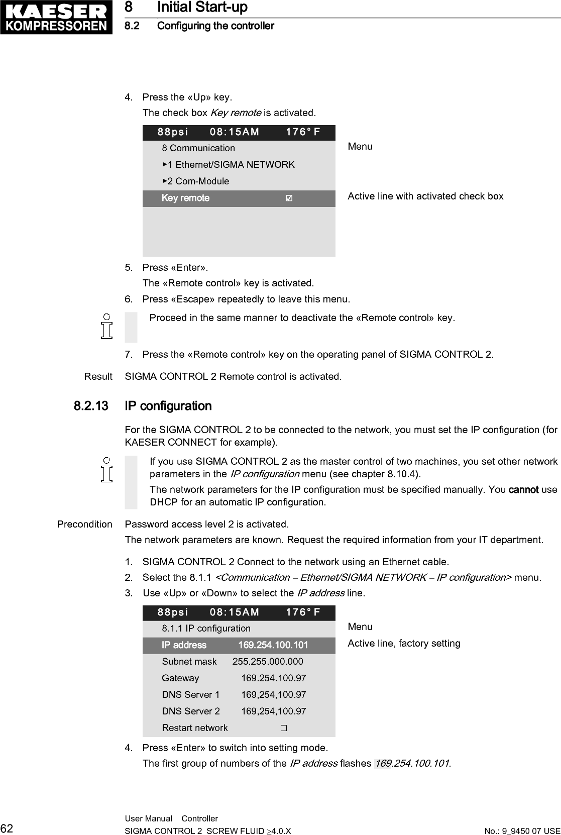
![Precondition Password access level 2 is activated.1. Select the 5.4 <Configuration – Compressor start> menu.2. Press «Enter».The Compressor start menu is displayed.88psi 08:15AM 176° F5.4 Compressor start Menu▶1 Compressor on Active line▶2 Compressor off ·········Autostart: ☑ Autostart activated Target 10 s ¦ Actual 0 s ·········Setting up the Autostart delay periodIf you operate several machines, it is better to start them in sequence.Use the "Delay time for Autostart" table to plan the time-delayed machine start. In the "Startperiod" column, enter for each individual machine the real time required for the first possibleLOAD. Cumulatively add these values in the "Delay time" column. Enter the value of the de‐lay time of each machine in the corresponding controller.The first machine may start immediately and does not require a delay time.Machine number Start time [sec] Delay time [sec]1 –– ––2345678910111213141516Tab. 62 Autostart delay periodPrecondition Password access level 2 is activated.8 Initial Start-up8.5 Configuring machine start and stop92 User Manual Controller SIGMA CONTROL 2 SCREW FLUID ≥4.0.X No.: 9_9450 07 USE](https://usermanual.wiki/Prodrive-Technologies/SC2MCSIO/User-Guide-3397040-Page-102.png)