Proventix Systems CU3000 Control Unit CU3000 User Manual 10 0364 Exhibit Cover
Proventix Systems Inc. Control Unit CU3000 10 0364 Exhibit Cover
UserManual.wiki
>
Proventix Systems
>
CU3000 User Manual
Manual
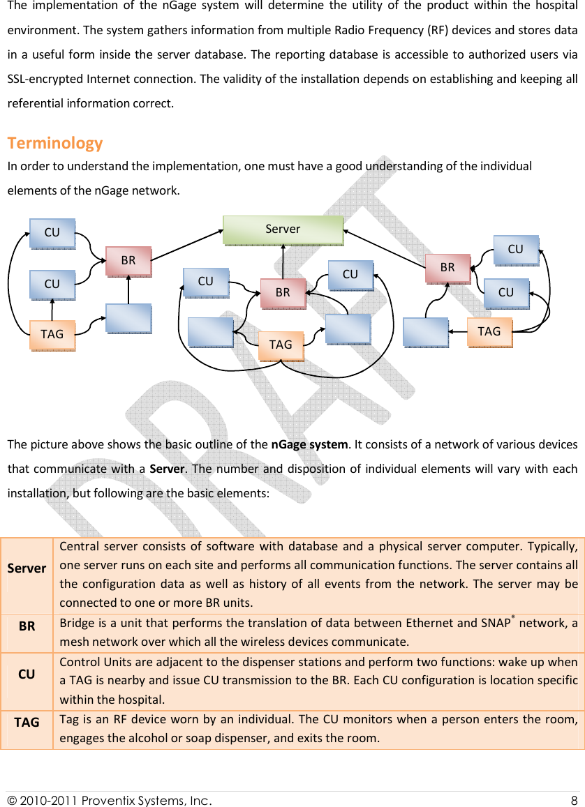
Navigation menu
Upload a User Manual
Namespaces
Wiki Guide
HTML
PDF
Info
Views
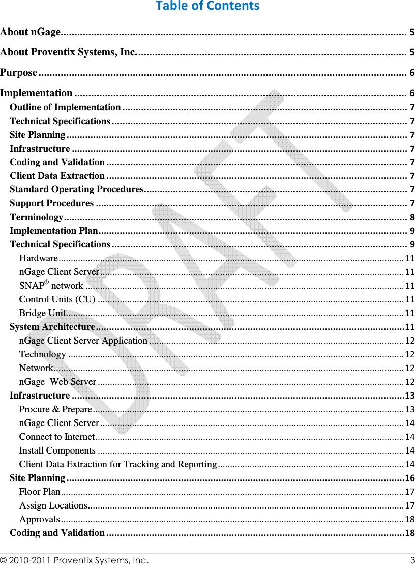
User Manual
Discussion / Help
Navigation


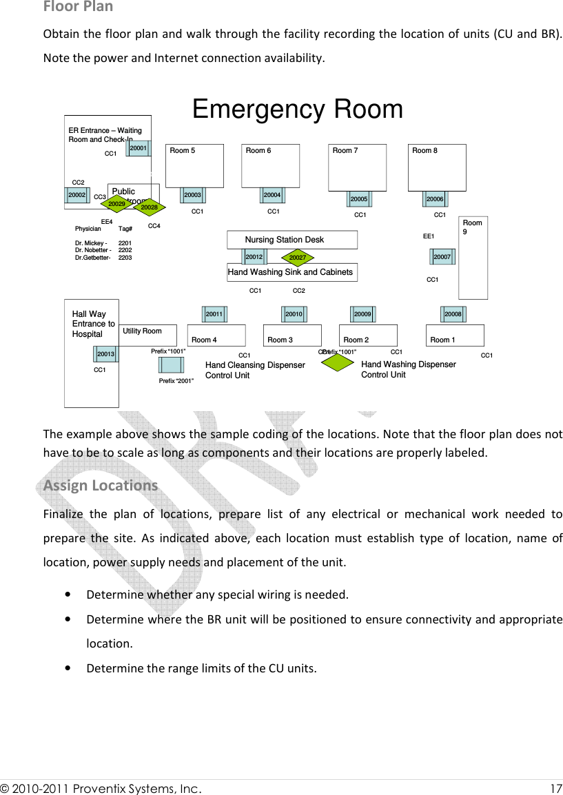
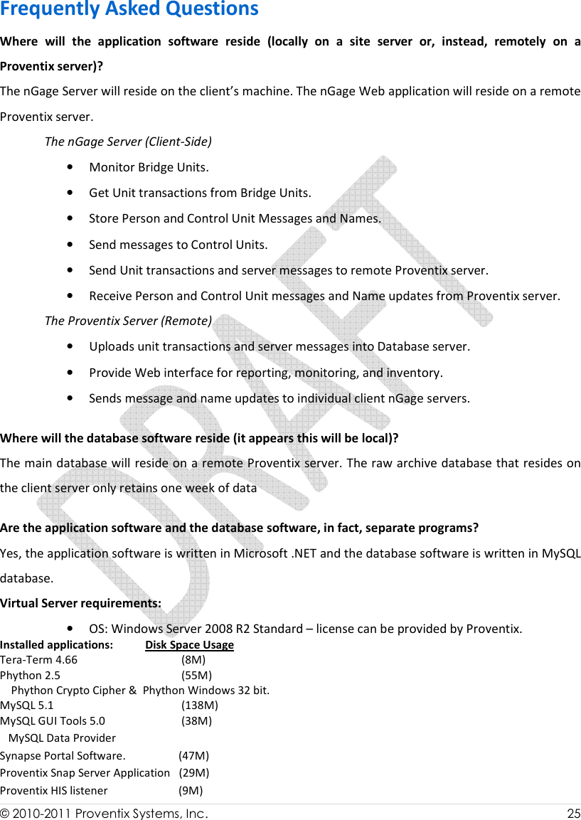
![© 2010-2011 Proventix Systems, Inc. 15 o The census report is used with ADT to build an accurate facility census and patient movement model. ADT alone does not allow us to do this. • HIS Census File Specification o The HIS census file contains the roster of the hospital patients at a particular date and time. o Each row describes one patient o All fields should be pipe ‘|’ delimited Field Field Description Required Site Client or hospital site ID. This identifies an individual hospital Yes Census date Format: MM/DD/YYYY [09/03/2004] Yes Census time HH:MM:SS Military time Yes Report date Date that the report was generated. Format: MM/DD/YYYY [09/03/2004] Yes MR number Medical record number Yes Account number Unique number for this patient’s current admission No Admission date Format: MM/DD/YYYY [09/03/2004] Yes Location Nursing station or ward [4W] Yes Room – Bed Room number –Bed Number Yes Patient name Last name, first name or last name, first name, middle initial Yes Patient DOB Date of birth Yes Patient age [60 or 6M] No Diagnosis Yes MD Attending physician name Yes Des Example: (this example shows a patient record without Account number and Patient age – both are optional fields) HOSPA|1/22/2004|0:00:00|1/22/2004|000123456||1/21/2004|4W|8-A|Doe, John, M | |5/22/1938||INCONTINENCE|Cure, All, MD| cription • Catalogs (if available) o Facility location catalog HL7 Specifications Our protocol follows the default HL7 standard. We listen, on the configured port, for HL7 (2.2 or 2.3) messages, with the following standard HL7 wrapper: <0x0B>data<0x1C><0x0D> Where “data” is a stream of HL7 data, typically ADT messages. The data content, including the format of the HL7 messages, is not validated by the listener.](https://usermanual.wiki/Proventix-Systems/CU3000/User-Guide-1489716-Page-16.png)
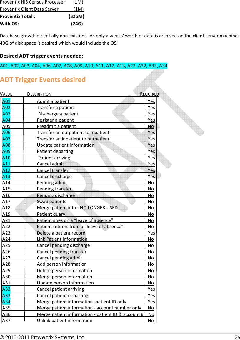
![© 2010-2011 Proventix Systems, Inc. 16 When we receive data in this wrapper, we immediately send back an acknowledgment in the following format: 0b 4d 53 48 7c 5e 7e 5c 26 7c 7c 7c 7c 7c 7c 7c .MSH|^ ~\&||||||| 41 43 4b 7c 47 7c 47 7c 32 2e 33 0d 4d 53 41 7c ACK|G| G|2.3.MSA| 41 41 7c 46 0d 1c 0d AA|F.. . No other wrapper / ACK / NAK is expected. Below is our preferred HL7 file layout (v2.3). Versions 2.1 and 2.2 layouts are available upon request. If your default HL7 file layout differs from this, please let us know. We can accept data in many different formats, as long as the required fields are sent. (minimum desired ADT trigger events are listed in FAQ section at the end of this document). ADT 2.3 MSH_MessageControlId MSH/MessageControlID 2.3 MSH_MessageDateTime_Day MSH/DateTimeOfMessage/Time/Day 2.3 MSH_MessageDateTime_Hours MSH/DateTimeOfMessage/Time/Hours 2.3 MSH_MessageDateTime_Minutes MSH/DateTimeOfMessage/Time/Minutes 2.3 MSH_MessageDateTime_Month MSH/DateTimeOfMessage/Time/Month 2.3 MSH_MessageDateTime_Year MSH/DateTimeOfMessage/Time/Year 2.3 MSH_SendingApplication MSH/SendingApplication/NamespaceID 2.3 MSH_SendingFacility MSH/SendingFacility/NamespaceID 2.3 AccountNumber PID/PatientAccountNumber/IDNumber 2.3 AdmissionDateTime_Day PV1/AdmitDateTime/Time/Day 2.3 AdmissionDateTime_Hours PV1/AdmitDateTime/Time/Hours 2.3 AdmissionDateTime_Minutes PV1/AdmitDateTime/Time/Minutes 2.3 AdmissionDateTime_Month PV1/AdmitDateTime/Time/Month 2.3 AdmissionDateTime_Year PV1/AdmitDateTime/Time/Year 2.3 AdmittingDiagnosisCode DG1[0]/DiagnosisCodingMethod 2.3 AdmittingDiagnosisDescription DG1[0]/DiagnosisDescription 2.3 AssigningFacility PID/InternalPatientID/AssigningFacility 2.3 AttendingDoctor_FirstName PV1/AttendingDoctor[0]/GivenName 2.3 AttendingDoctor_LastName PV1/AttendingDoctor[0]/FamilyName 2.3 BirthDate_Day PID/DateTimeOfBirth/Time/Day 2.3 BirthDate_Month PID/DateTimeOfBirth/Time/Month 2.3 BirthDate_Year PID/DateTimeOfBirth/Time/Year 2.3 PatientAddress_Address1 PID/PatientAddress[0]/StreetAddress 2.3 PatientAddress_Address2 PID/PatientAddress[0]/OtherDesignation 2.3 PatientAddress_City PID/PatientAddress[0]/City 2.3 PatientAddress_State PID/PatientAddress[0]/StateOrProvince 2.3 PatientAddress_ZipCode PID/PatientAddress[0]/ZipOrPostalCode 2.3 PatientBed PV1/AssignedPatientLocation/Bed 2.3 PatientClass PV1/PatientClass 2.3 PatientFirstName PID/PatientName[0]/GivenName 2.3 PatientHomePhone PID/HomePhoneNumber[0]/PhoneNumberString 2.3 PatientId (Medical Record Number) PID/PatientIdentifierList[0]/IDNumber 2.3 PatientLastName PID/PatientName[0]/FamilyName 2.3 PatientLocation PV1/AssignedPatientLocation/PointOfCare 2.3 PatientRoom PV1/AssignedPatientLocation/Room 2.3 PatientType PV1/PatientType Site Planning The nGage system monitors the location of a person at a given time. The CU (Control Unit) detects a person’s position. A specific Tag associated with each individual detects who is near the CU range. Mapping of all the devices must be clearly understood and accurate.](https://usermanual.wiki/Proventix-Systems/CU3000/User-Guide-1489716-Page-17.png)