Psion 7530RA2040 HANDHELD COMPUTER User Manual 8000007 Book
Psion Inc HANDHELD COMPUTER 8000007 Book
UserManual.wiki
>
Psion
>
7530RA2040 User Manual
users manual
Navigation menu
Upload a User Manual
Namespaces
Wiki Guide
HTML
PDF
Info
Views
User Manual
Discussion / Help
Navigation


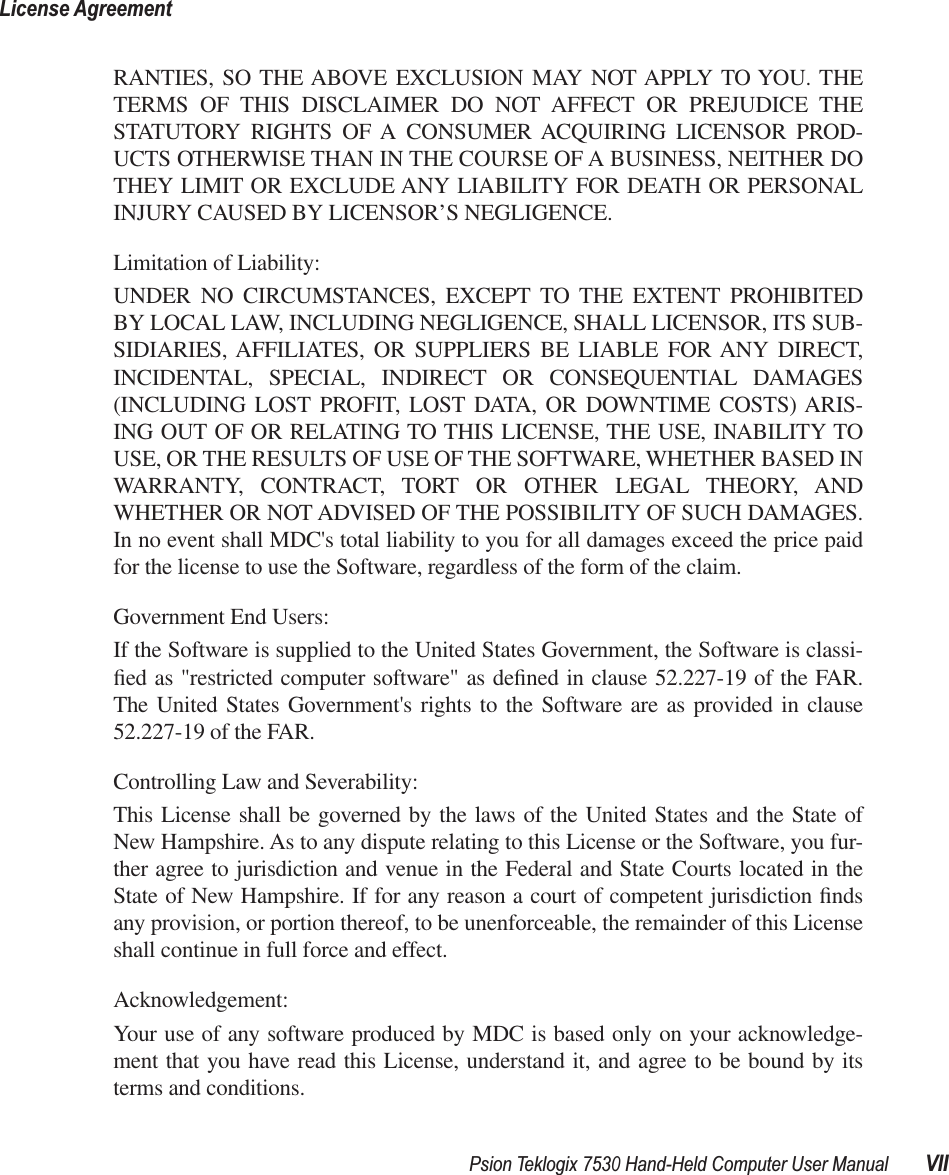
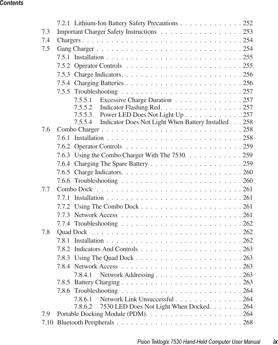
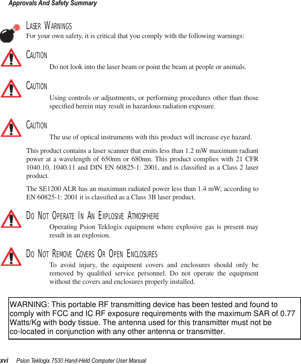
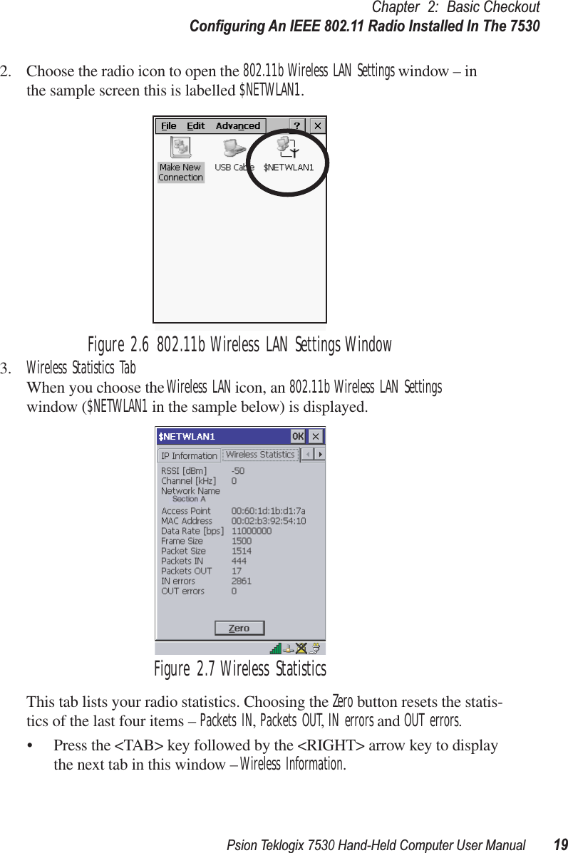

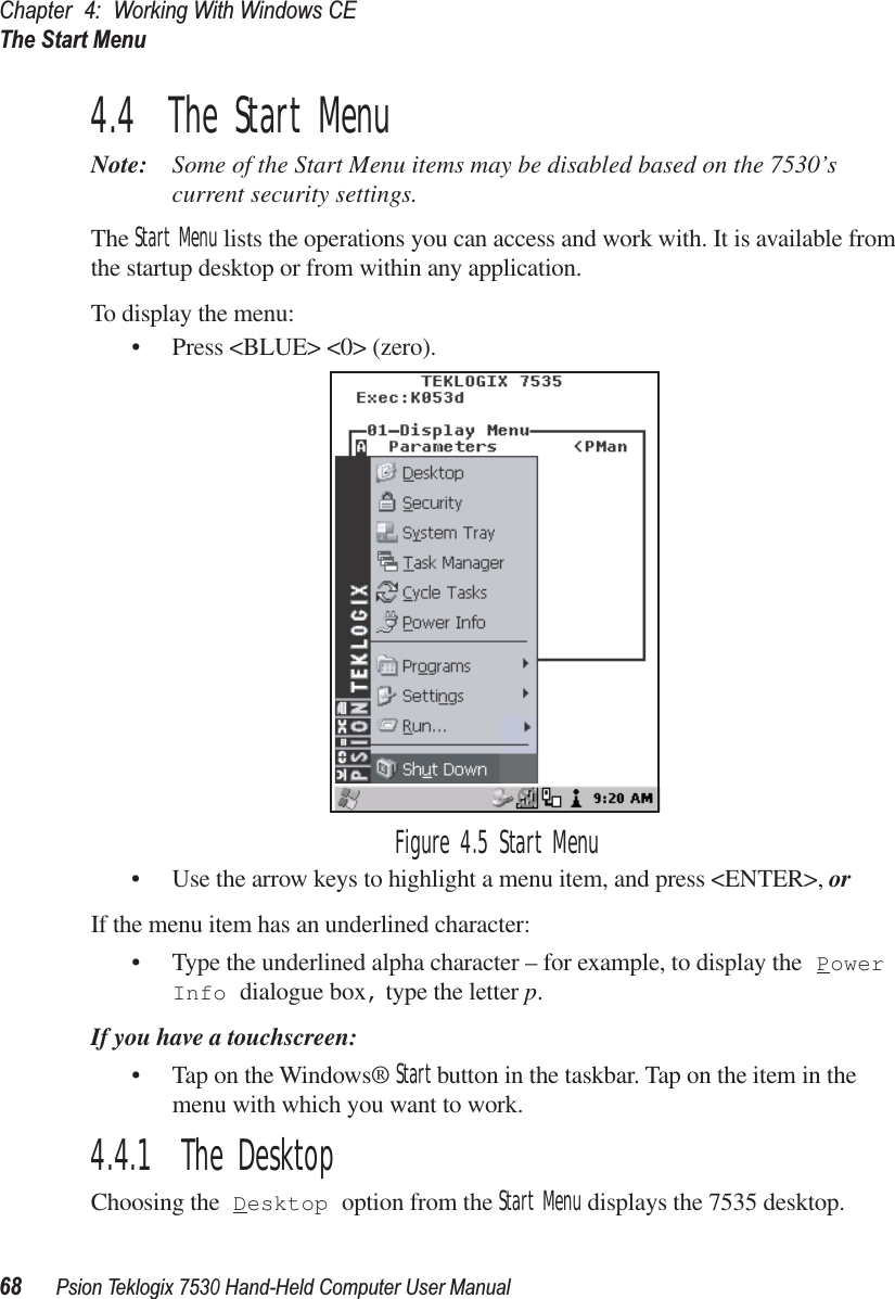
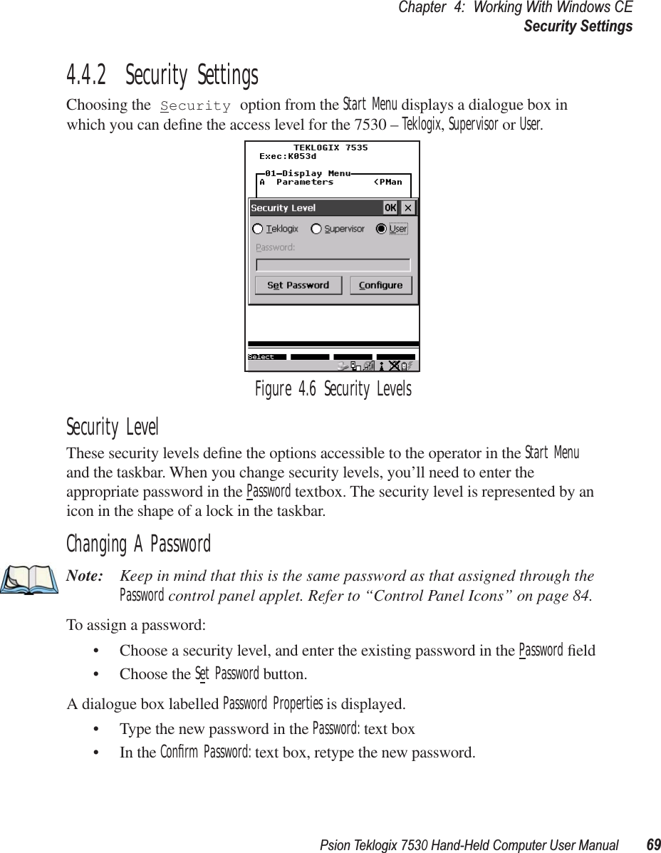
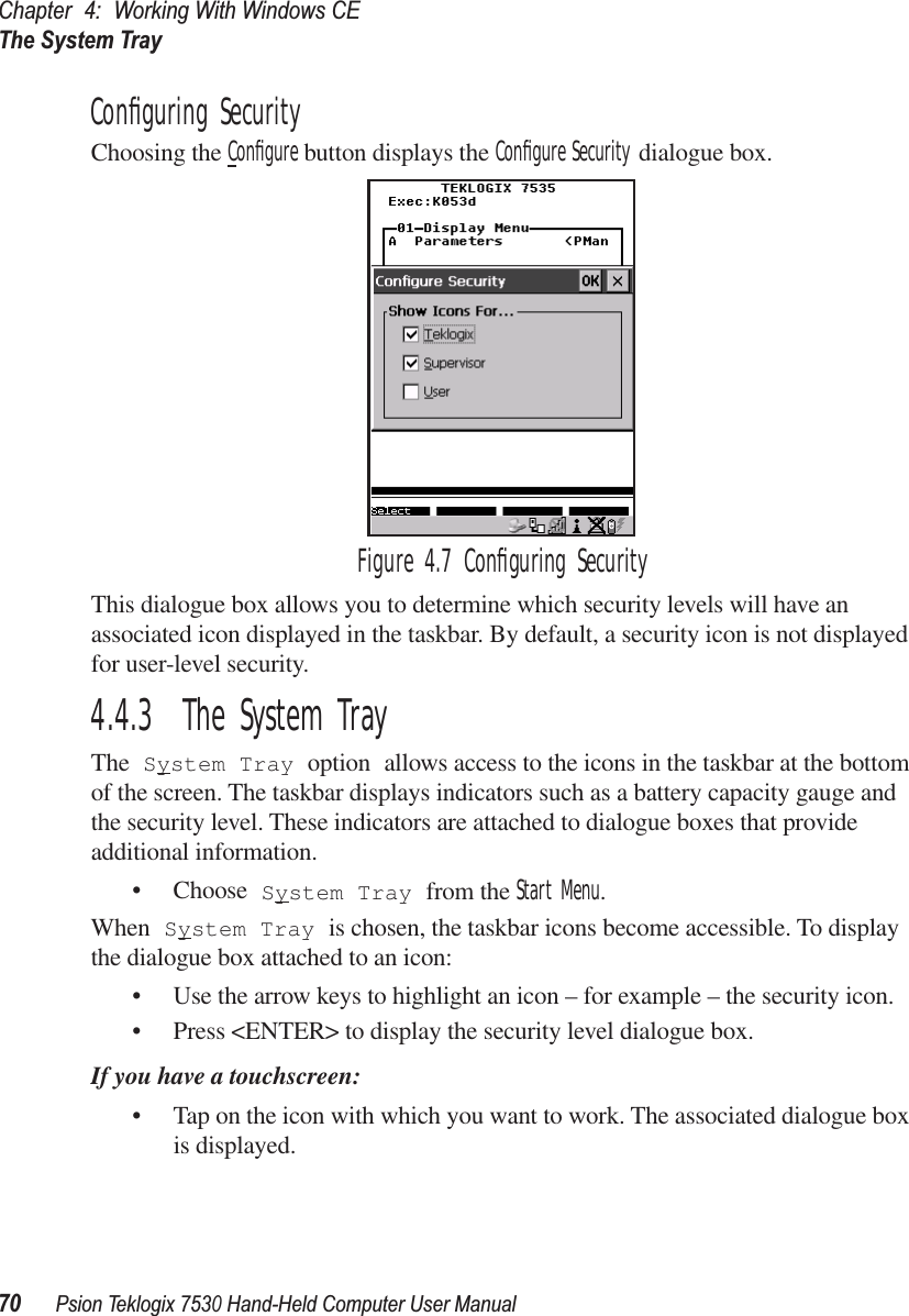
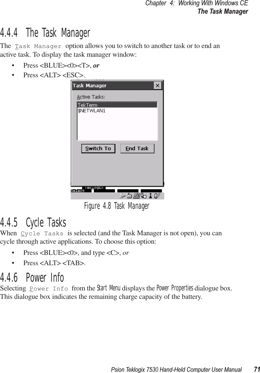
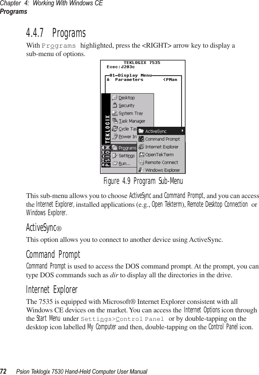

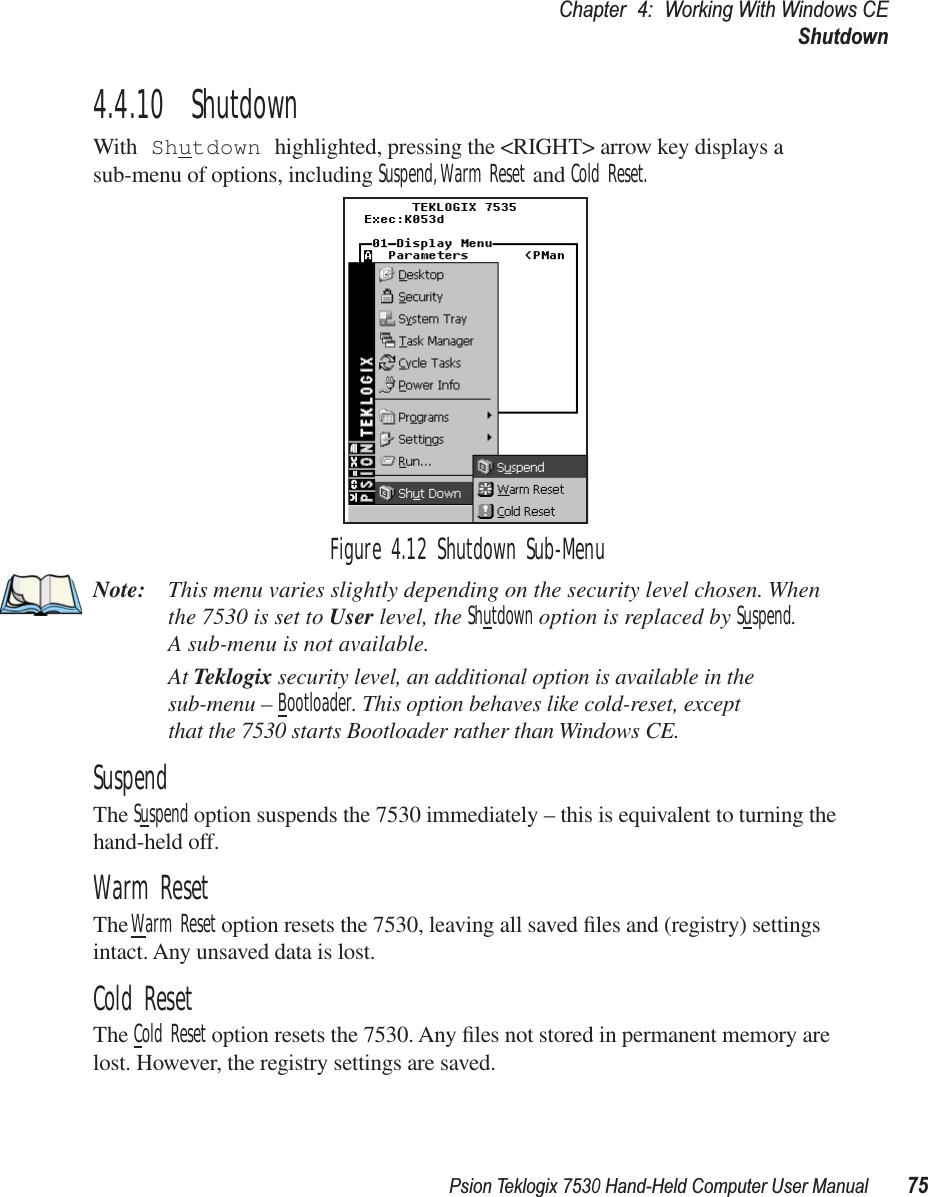
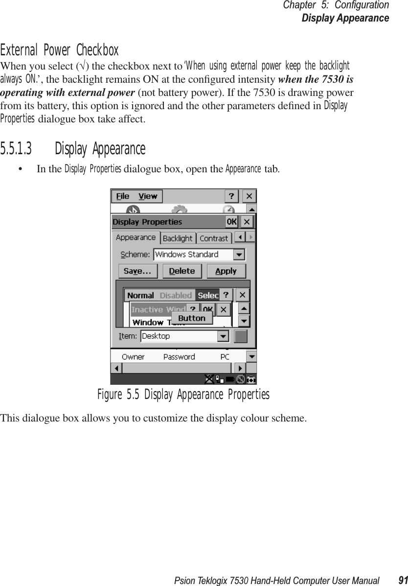
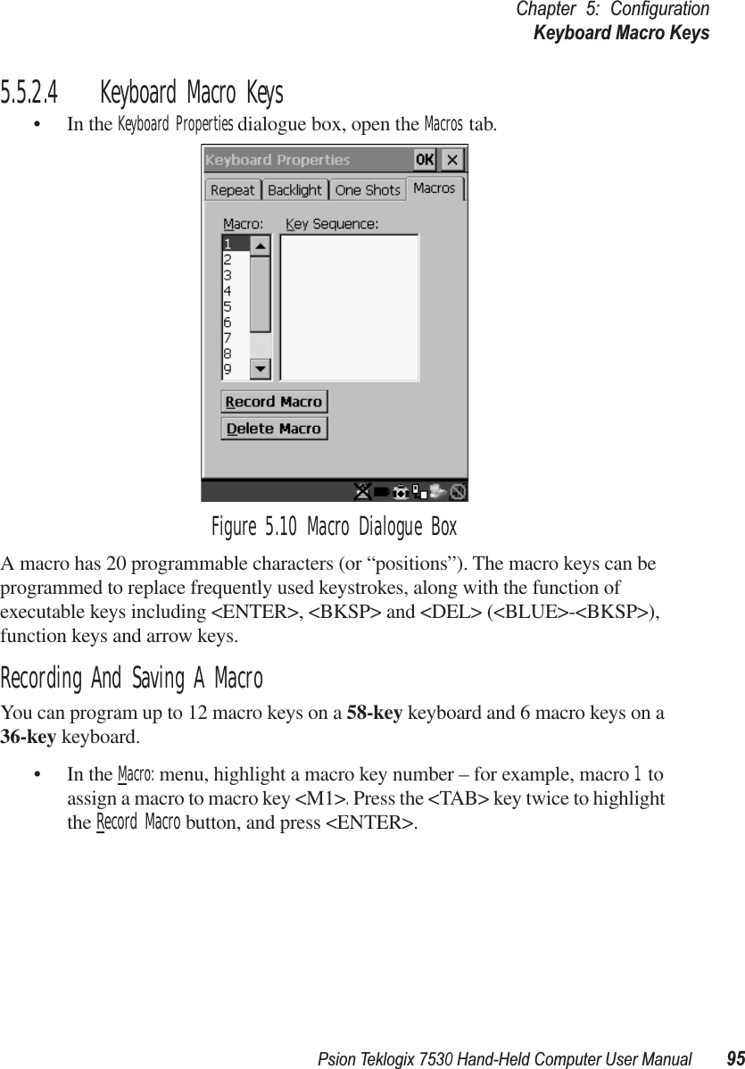
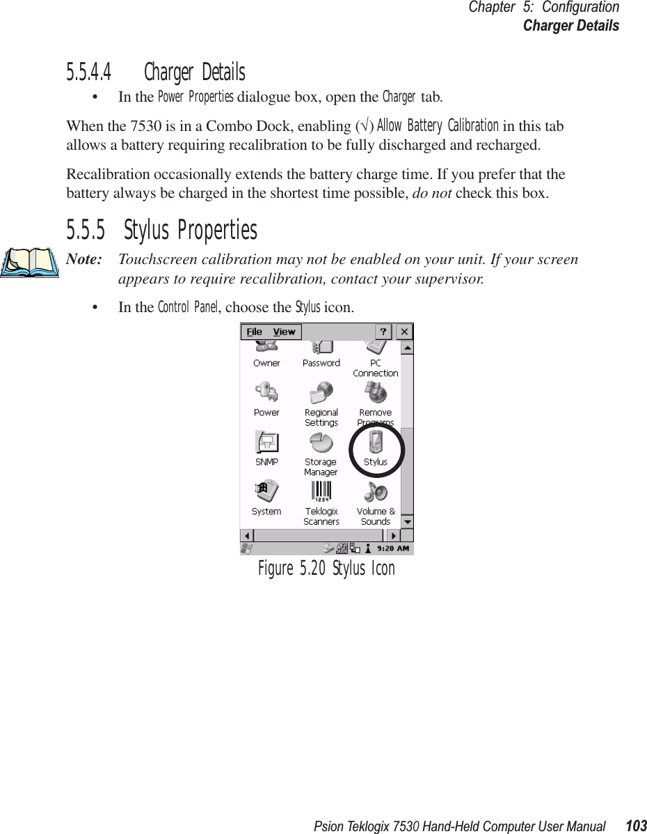
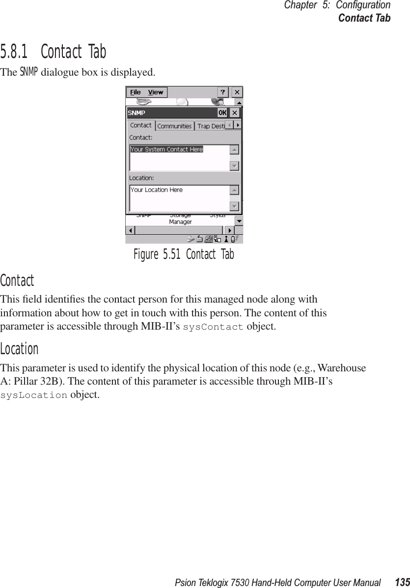
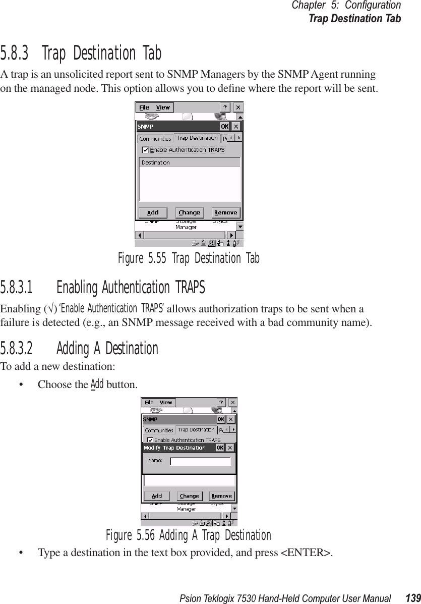
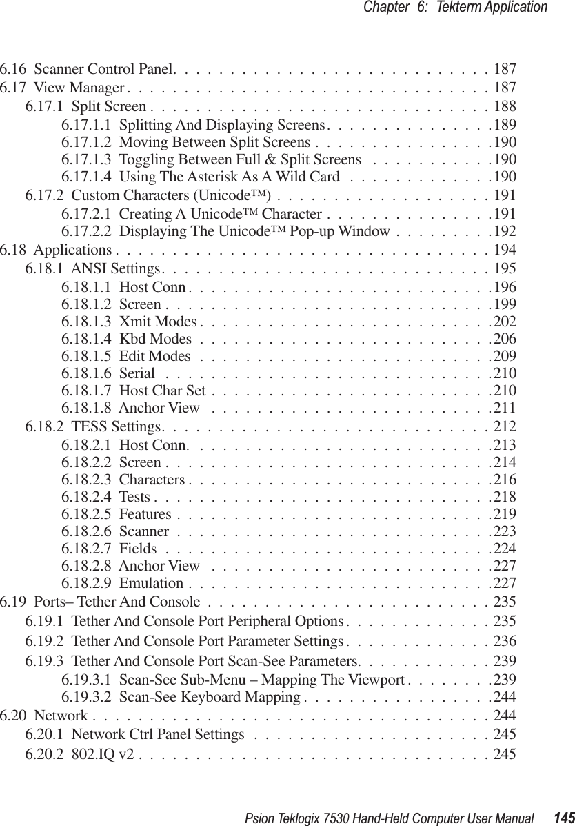
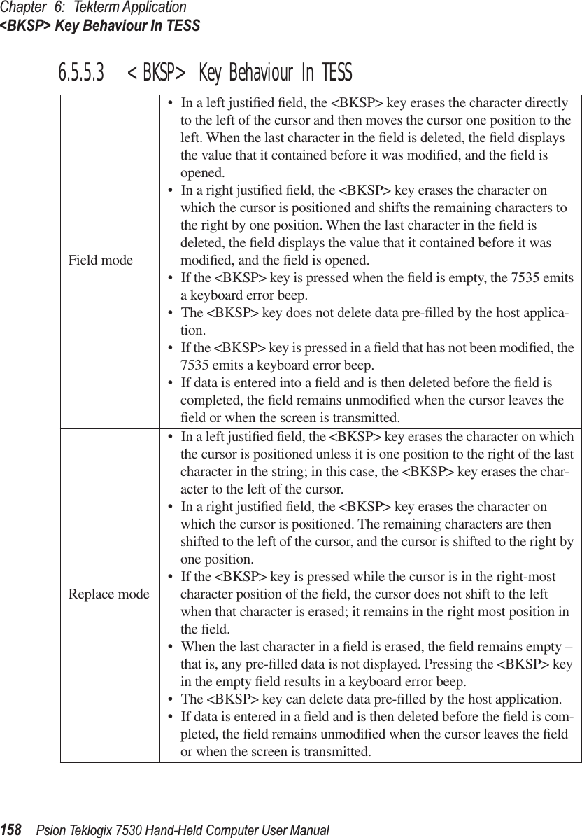
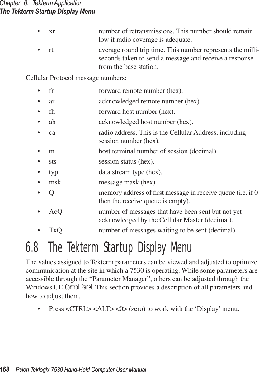
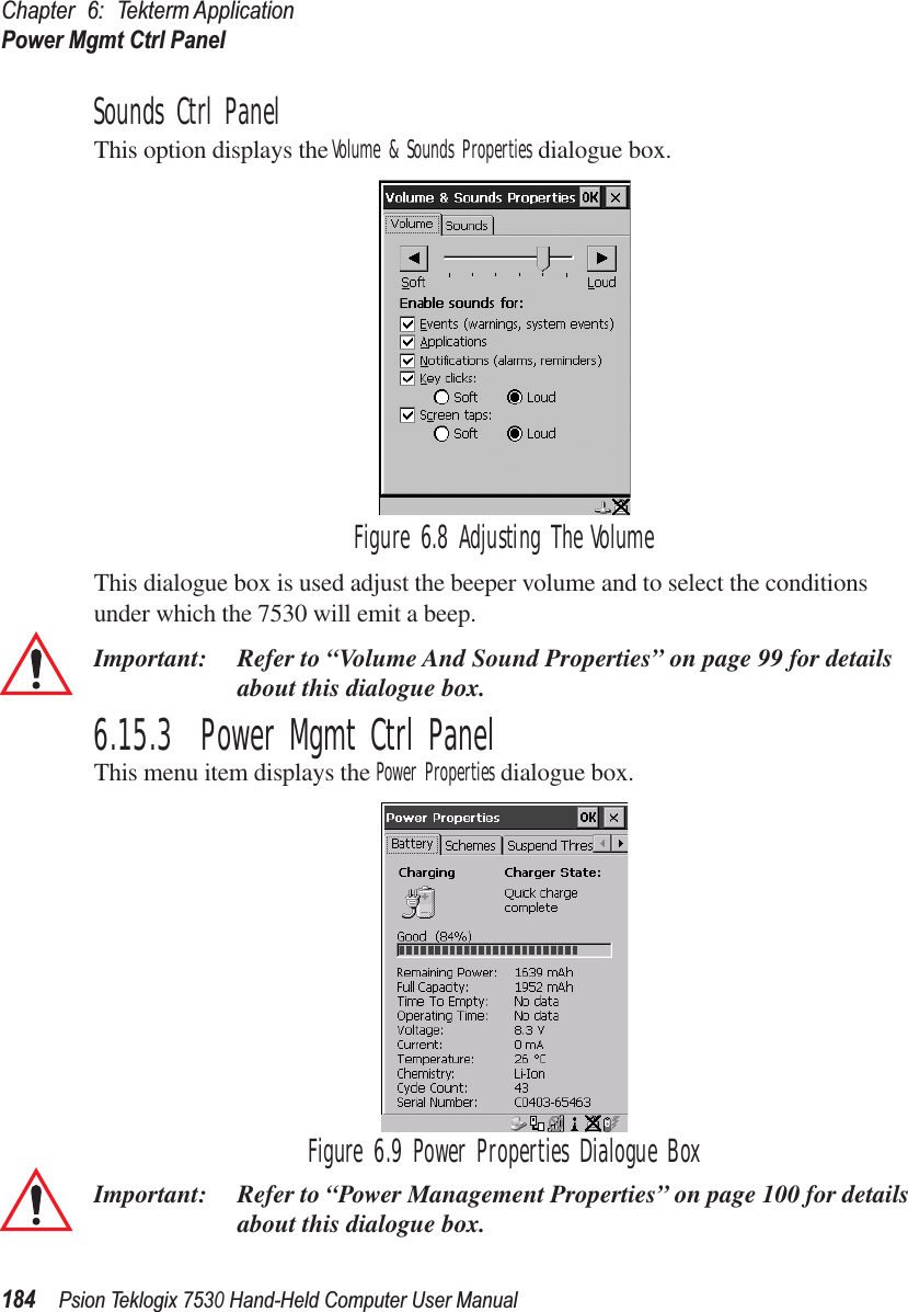
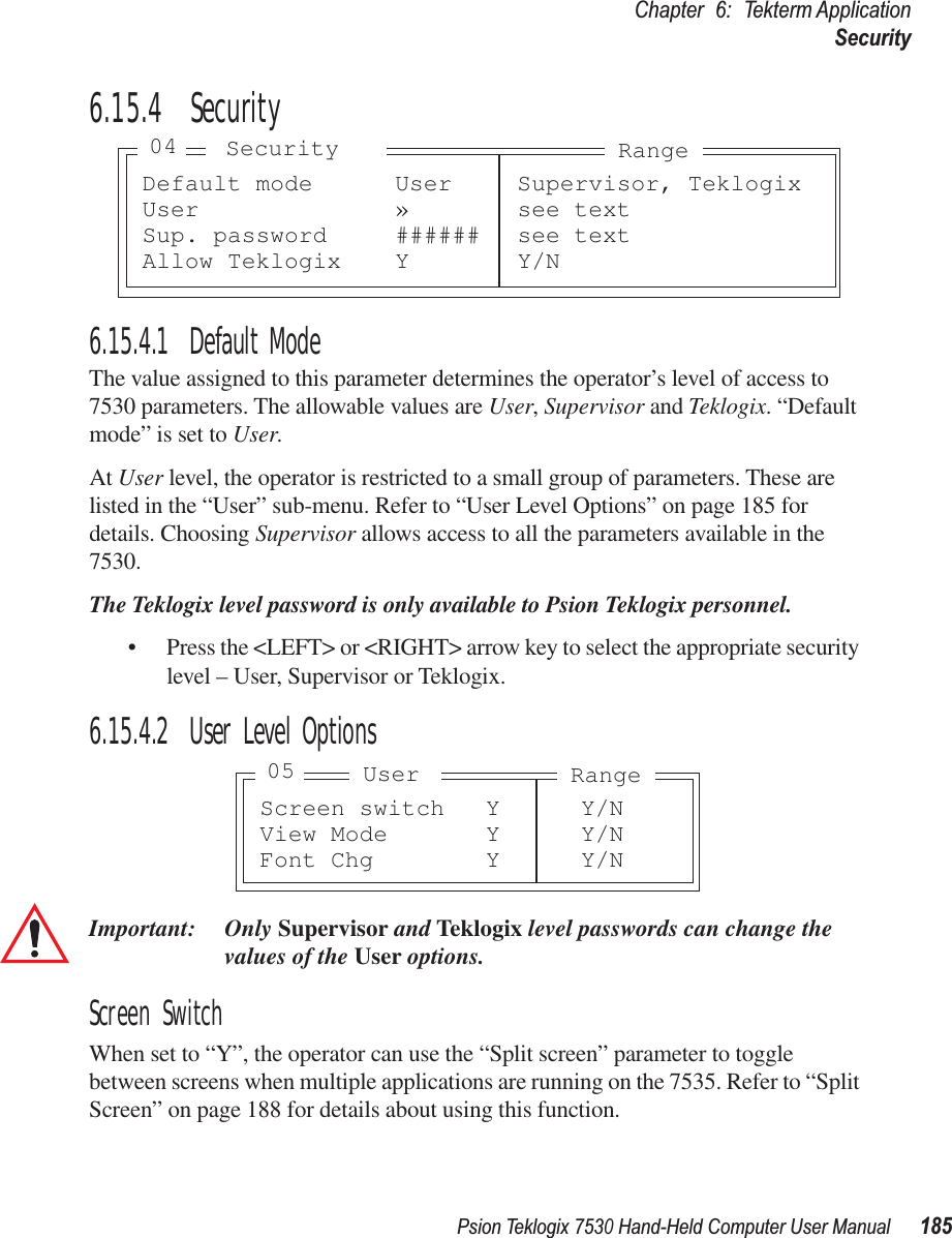
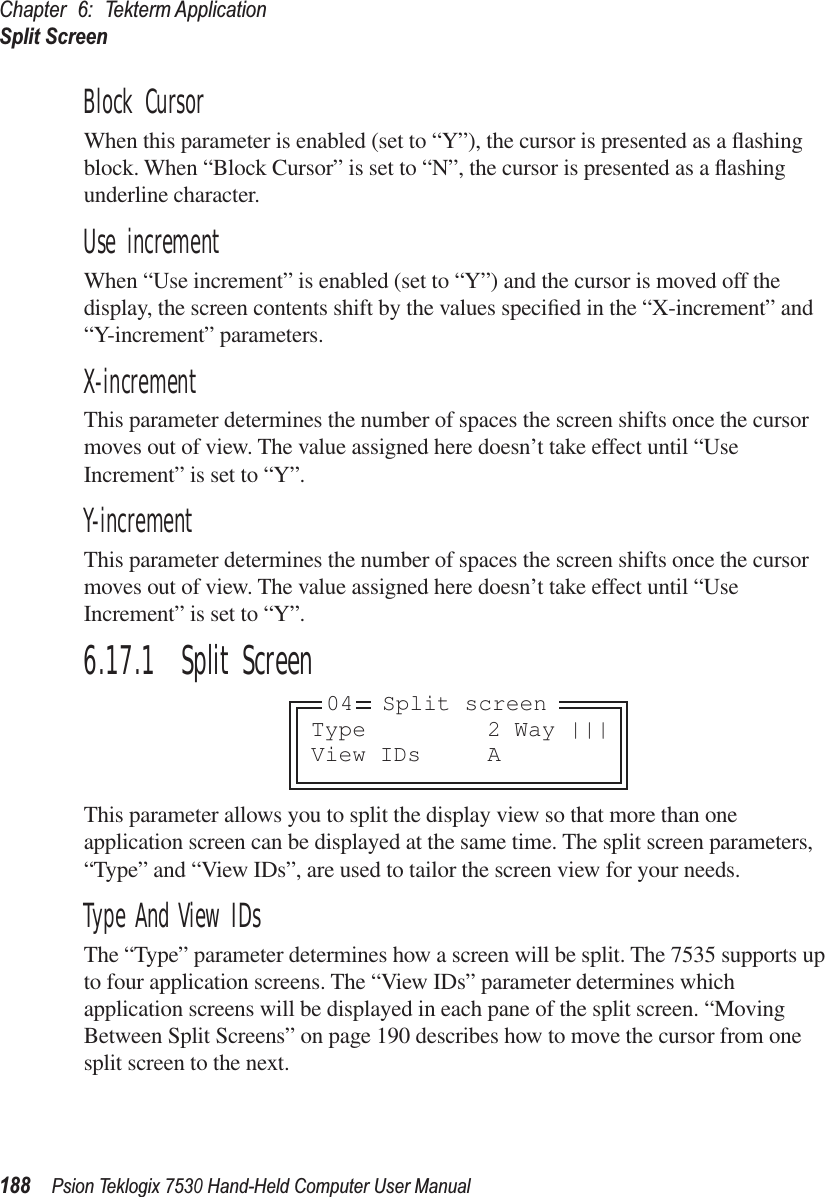
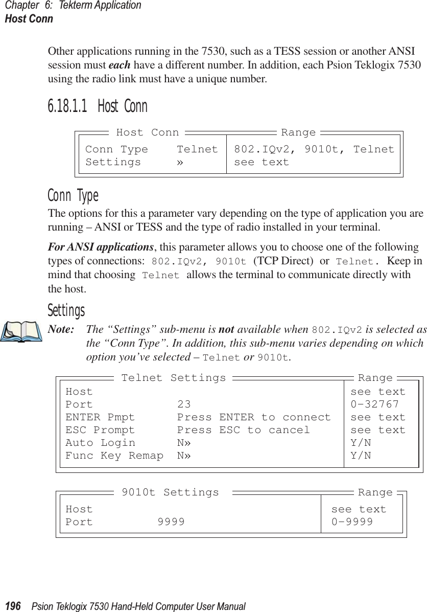
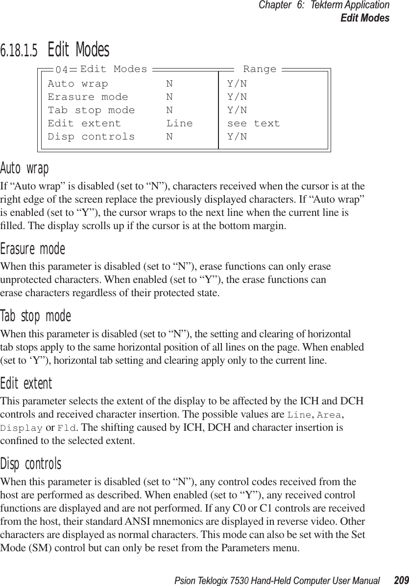
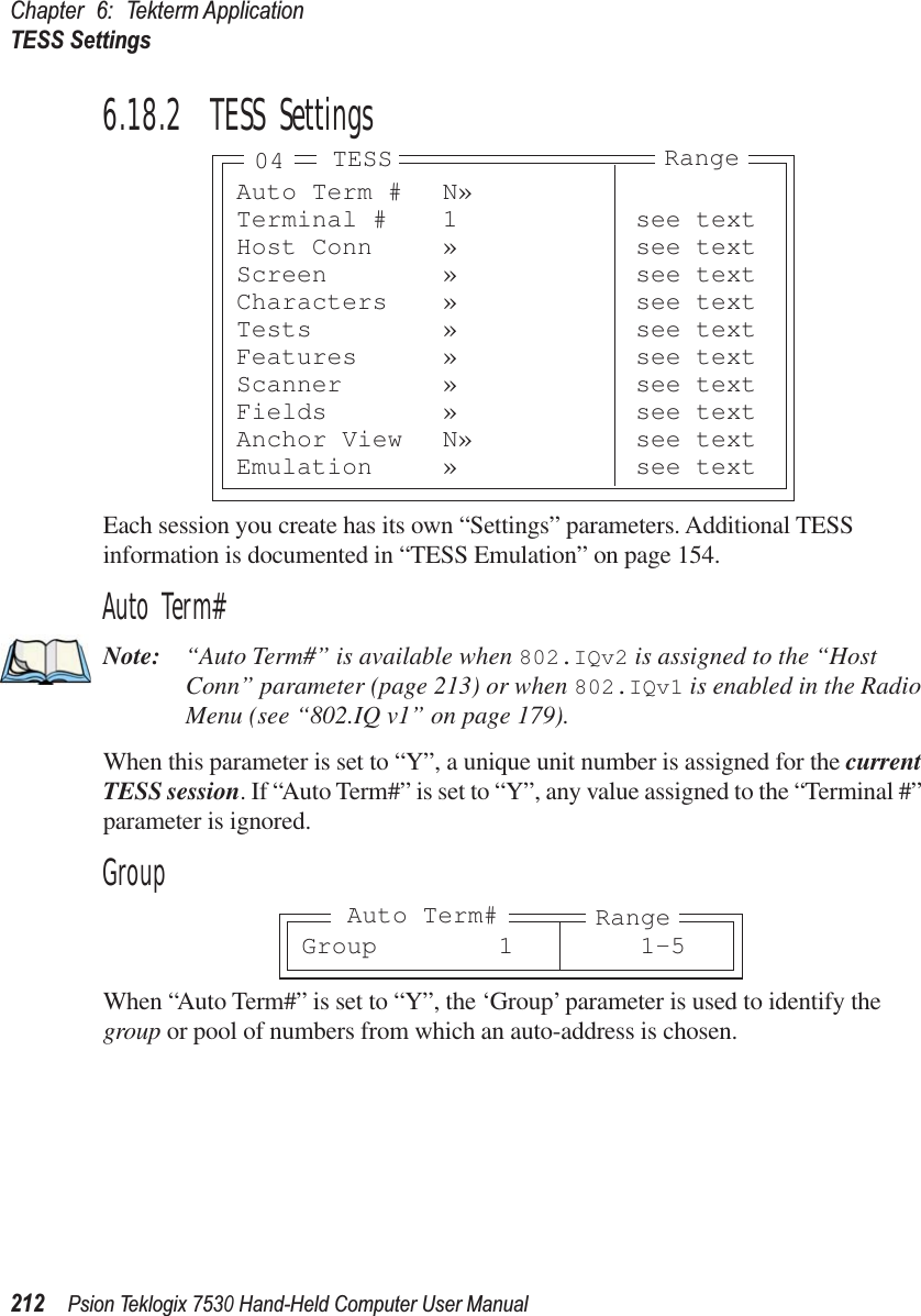
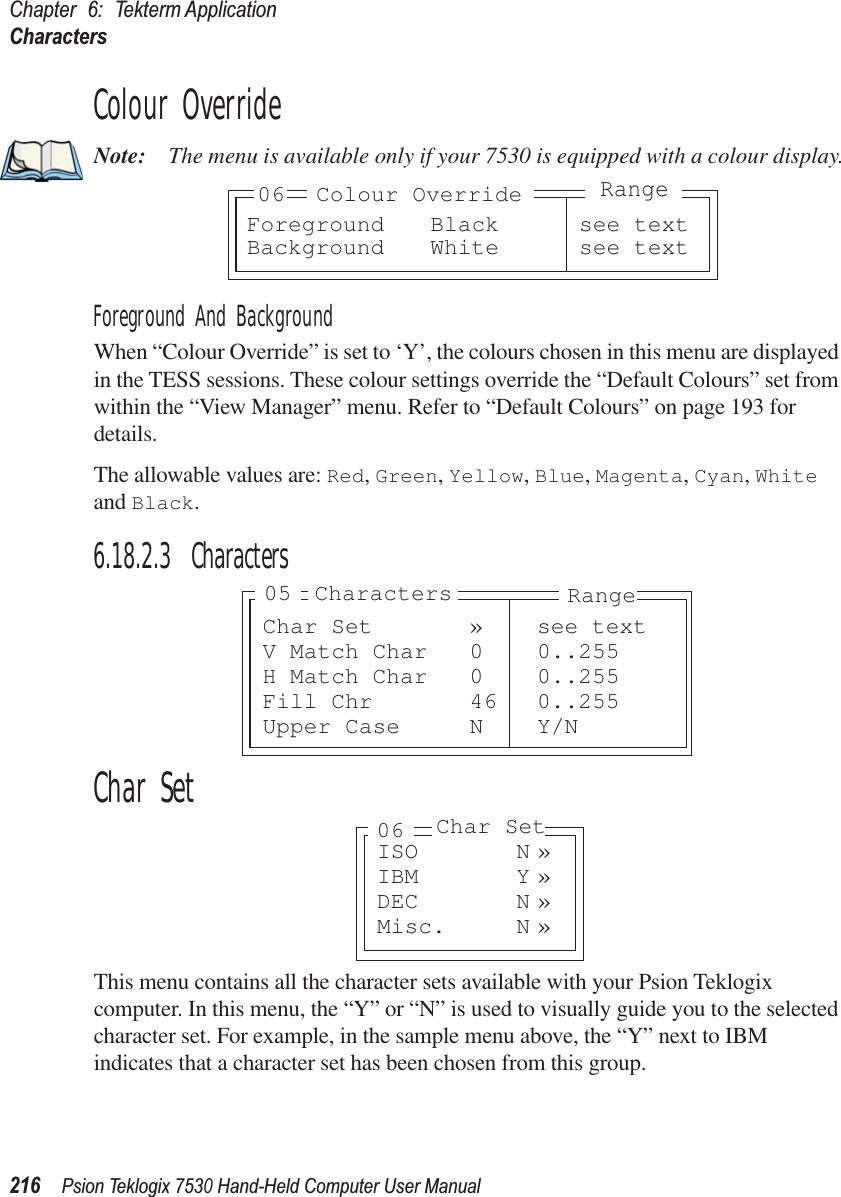
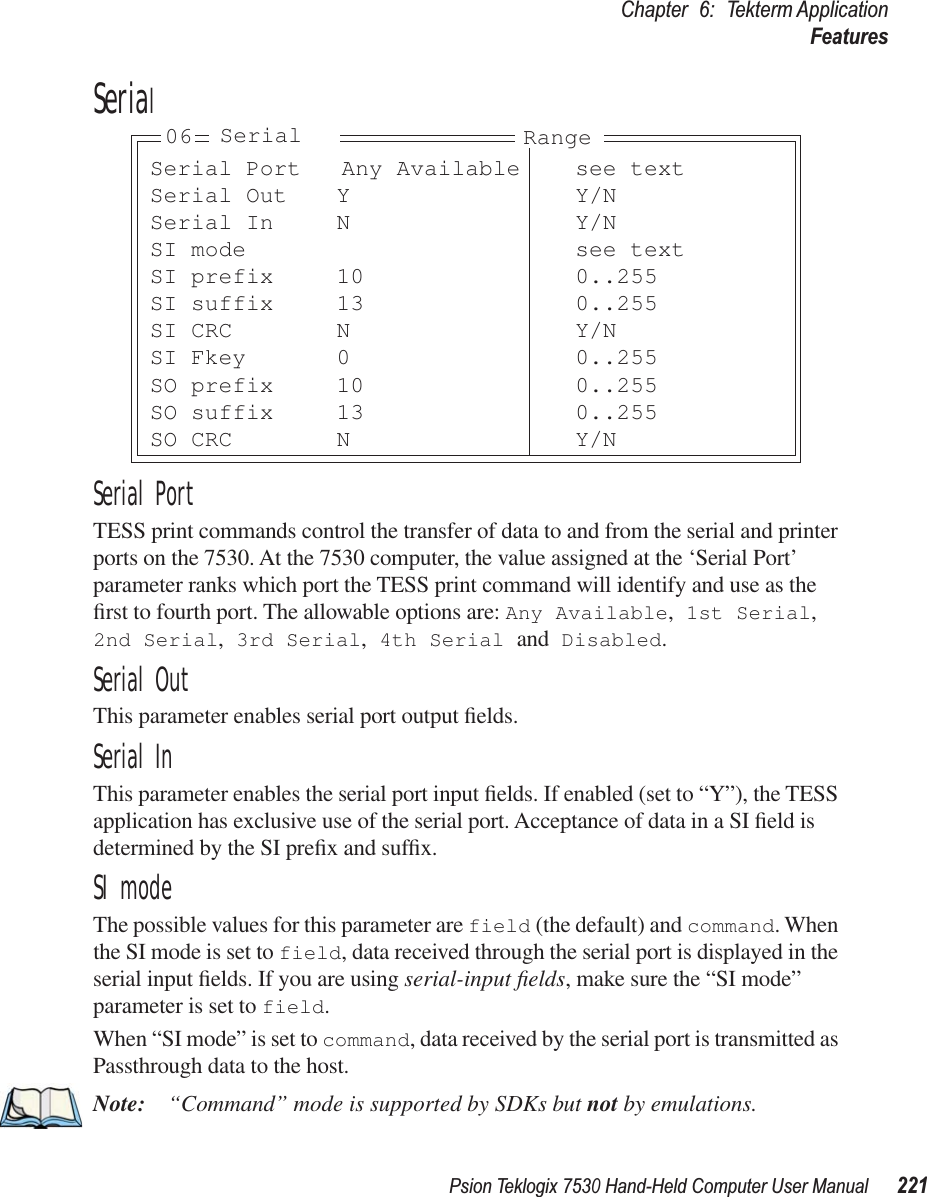
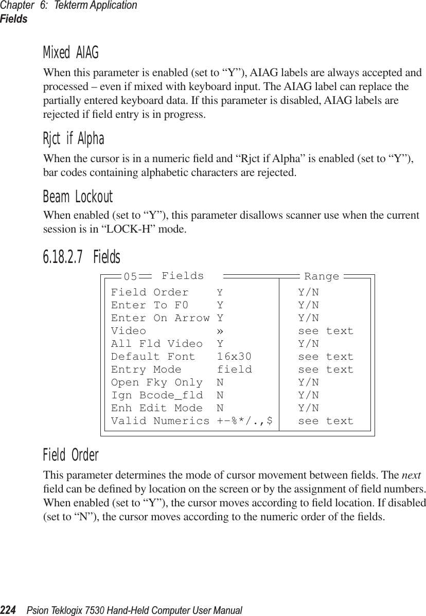
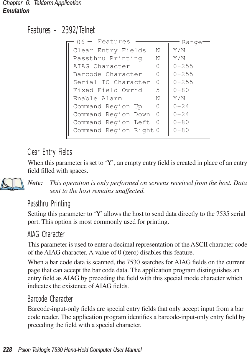
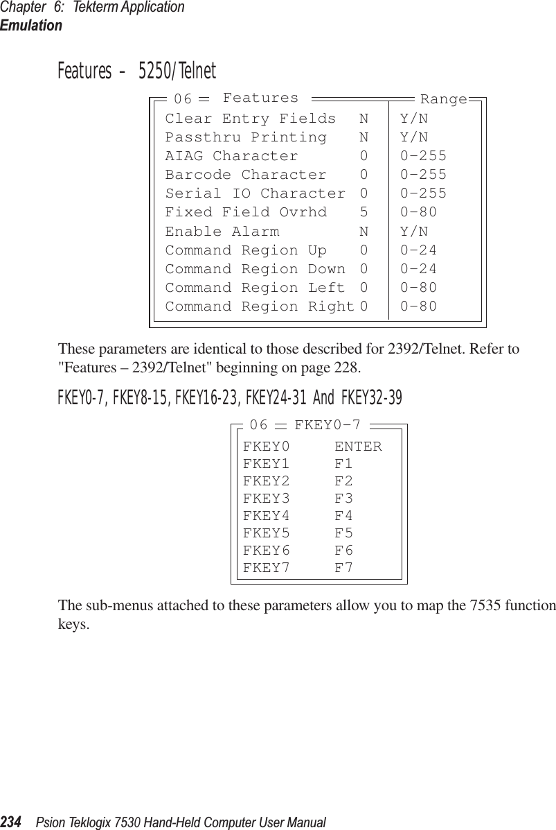
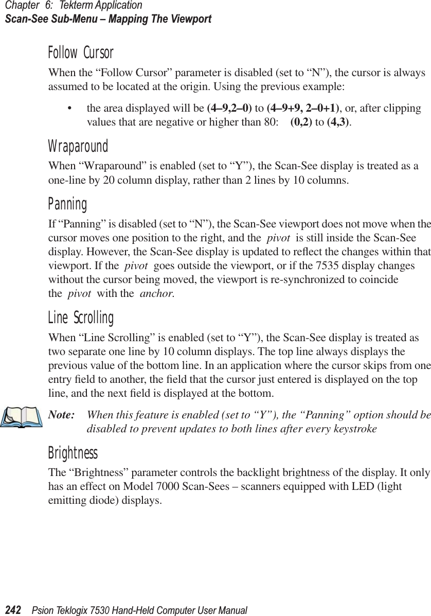
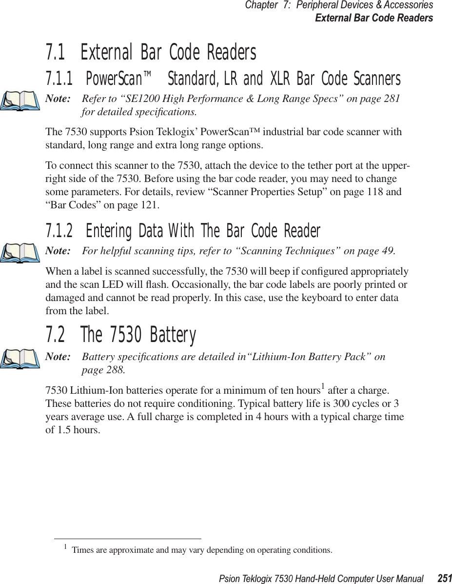
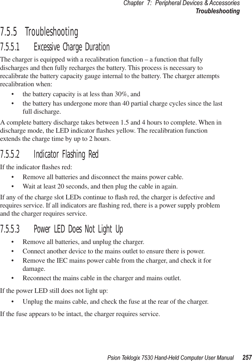
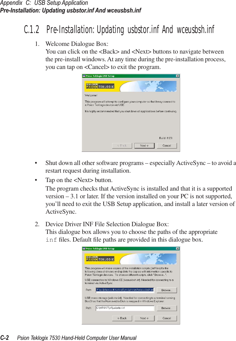
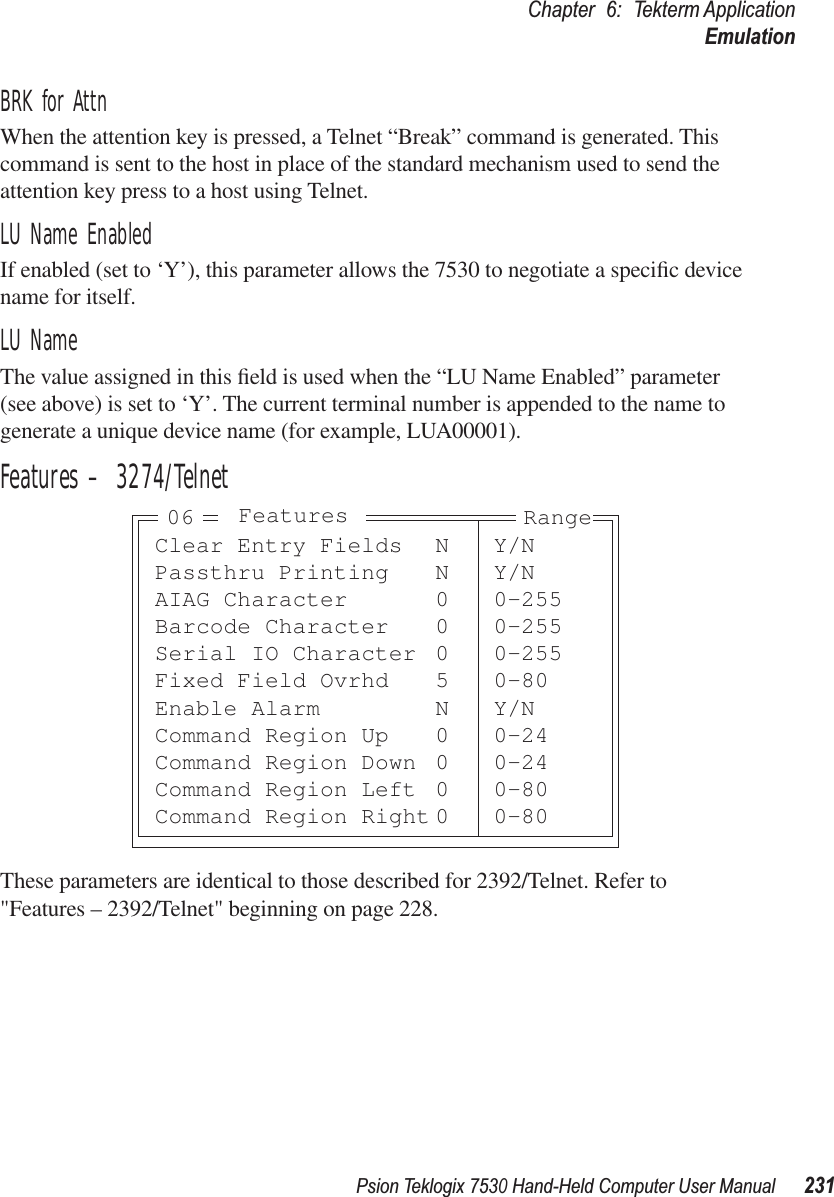
![Chapter 6: Tekterm ApplicationEmulation230Psion Teklogix 7530 Hand-Held Computer User Manual3274/Telnet EmulationFujitsu HostIf this parameter is set to ‘Y’, data is sent in Fujitsu format. Enabling ‘Fujitsu Host’ causes the standard IBM formatting codes (for start of field, setting buffers, etc.) to be replaced by the codes used by Fujitsu host computers.Intl EBCDICIf this parameter is enabled (set to ‘Y’), the ‘international’ EBCDIC character set is used, swapping the positions of the ! and ] characters.Nulls in FieldsSetting this parameter to ‘Y’ allows ‘null’ characters – e.g., hyphens (-) or periods (.) – to fill in empty entry fields.IP for SysReqWhen the system request key is pressed, a Telnet “Interrupt Process” command is generated. The “Interrupt Process” command is sent to the host in place of the standard mechanism used to send the system request key press to a host using Telnet.Fujitsu Host N Y/NIntl EBCDIC N Y/NNulls in Fields N Y/NIP for SysReq N Y/NBRK for Attn N Y/NLU Name Enabled N Y/NLU Name see textFeatures » see textFKEY0-7 » see textFKEY8-15 » see textFKEY16-23 » see textFKEY24-31 » see textFKEY32-39 » see textEmulation Range05](https://usermanual.wiki/Psion/7530RA2040/User-Guide-622286-Page-248.png)
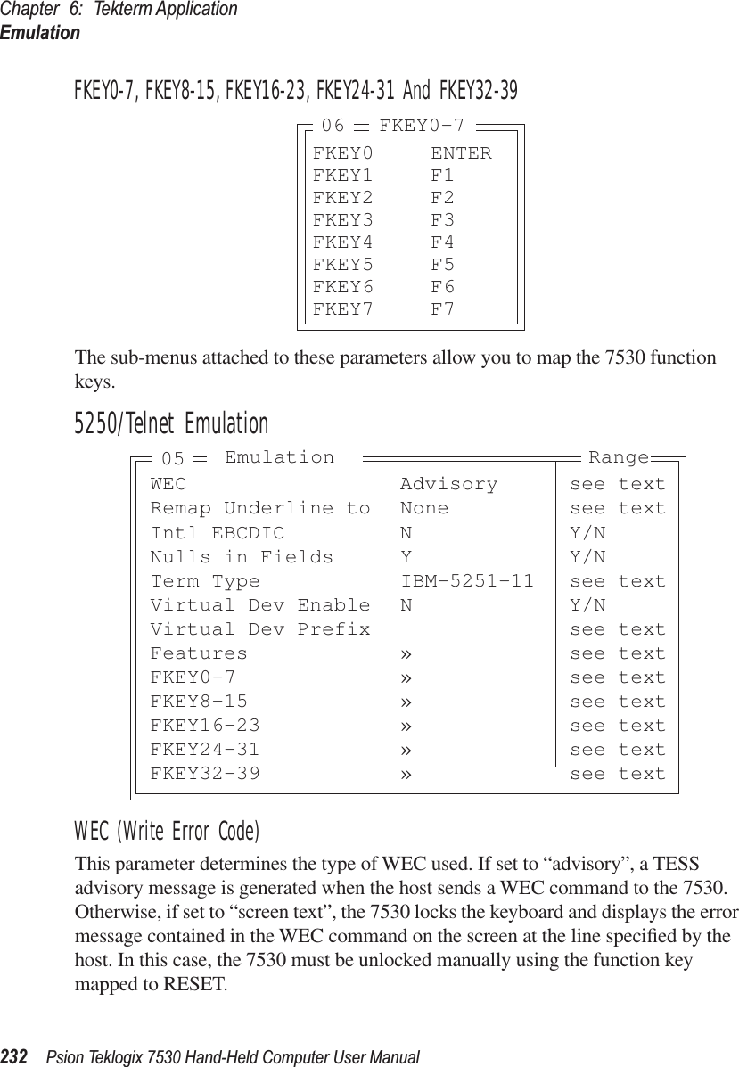
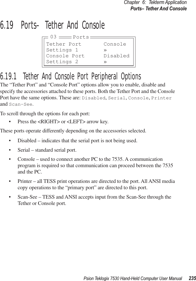
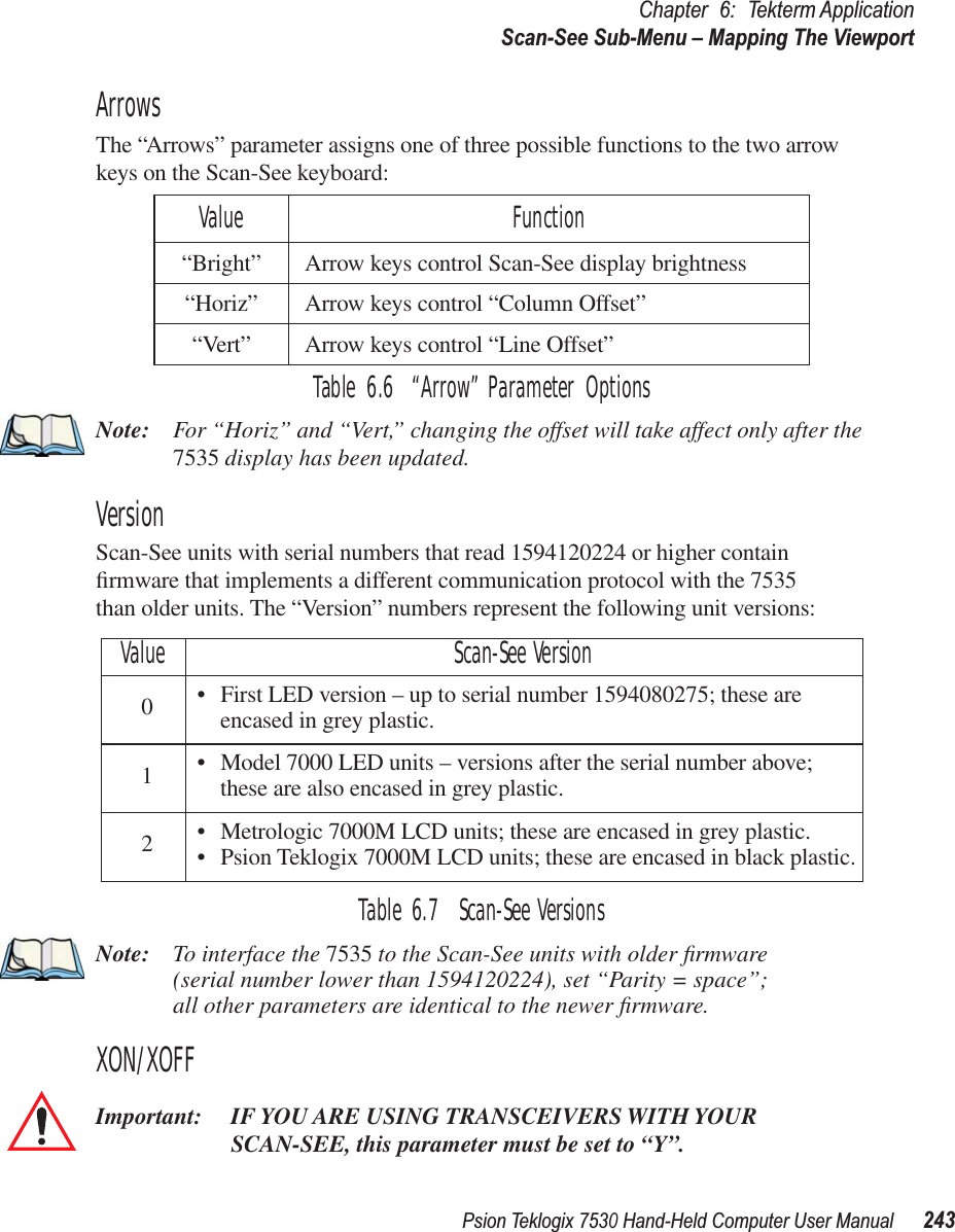
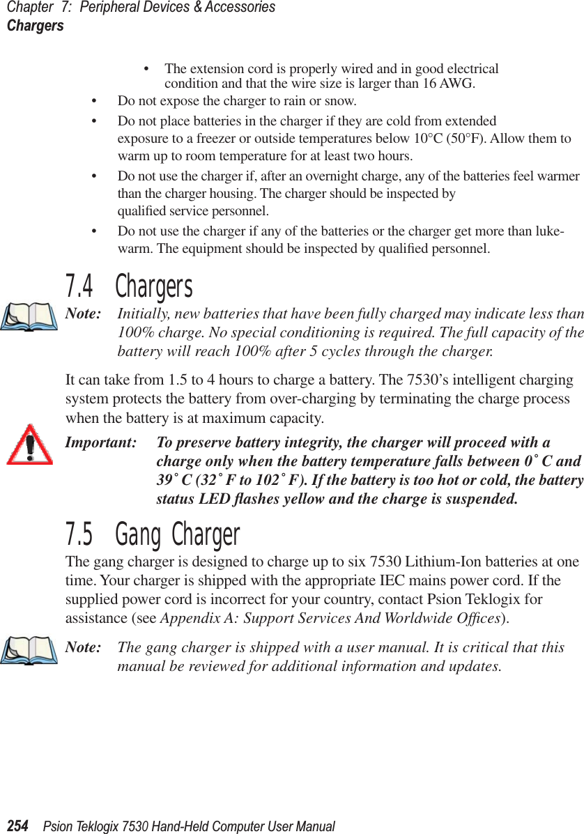
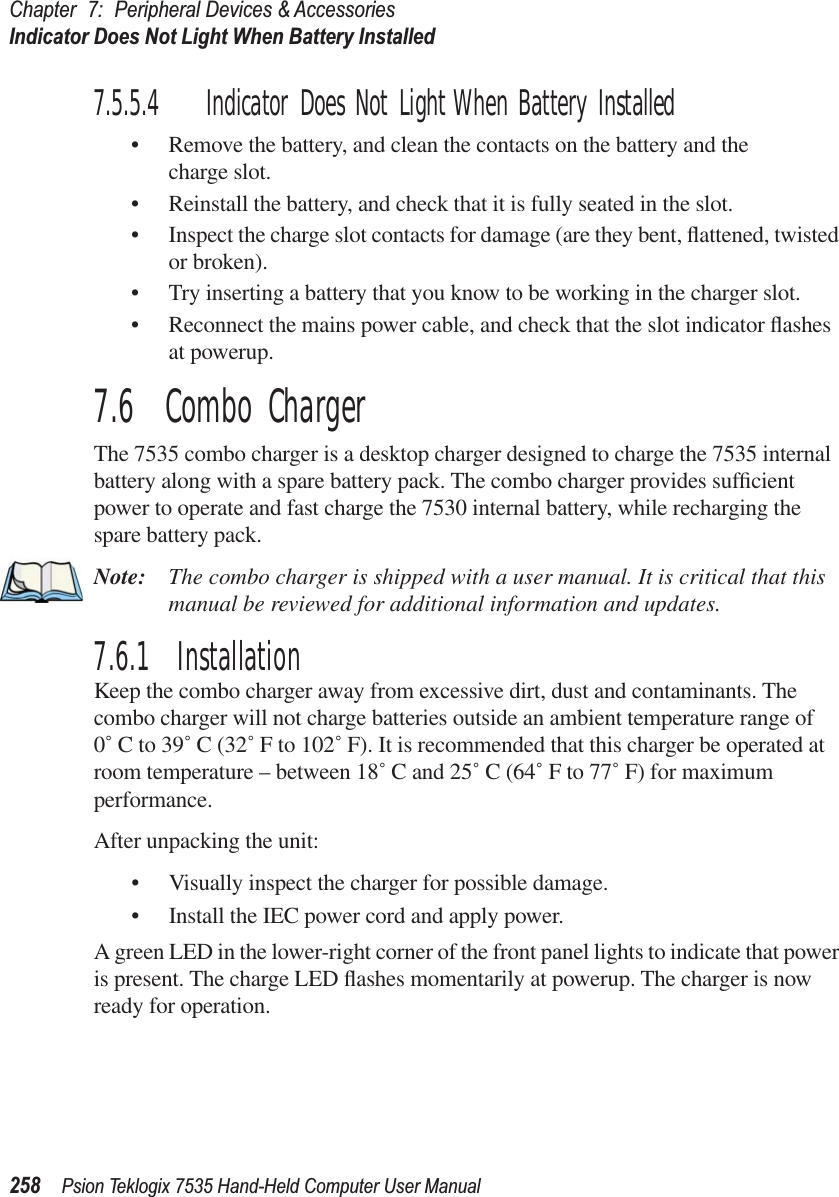
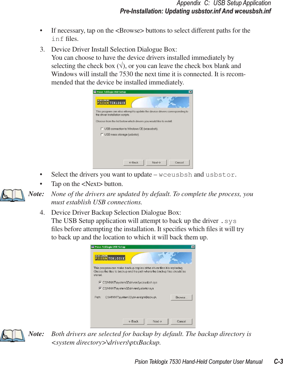
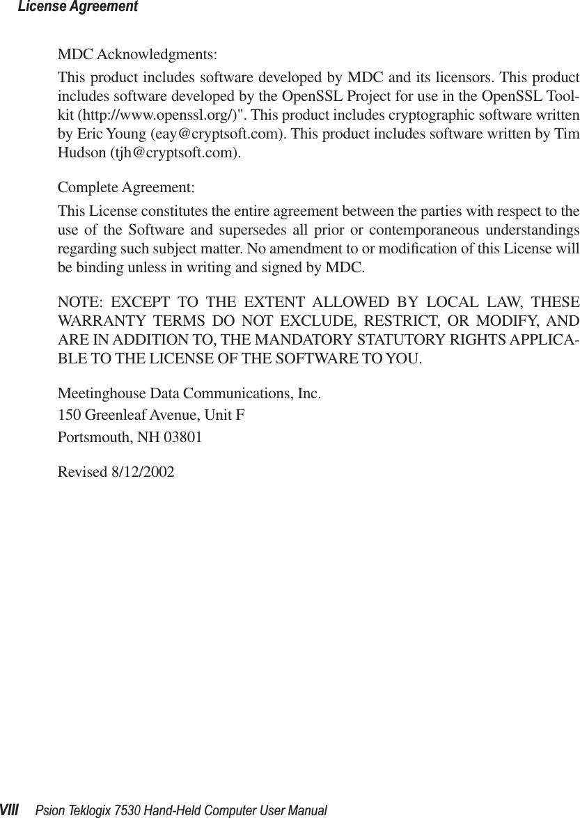
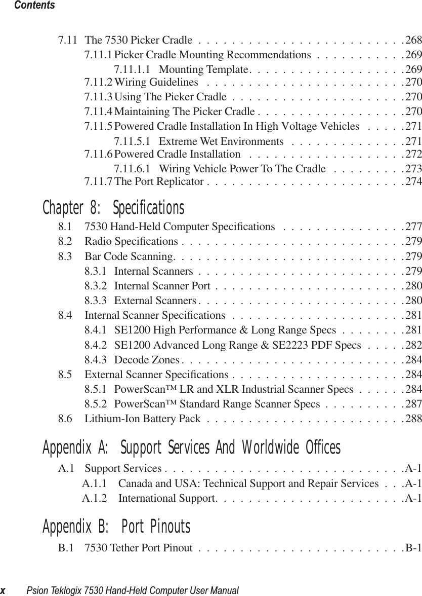
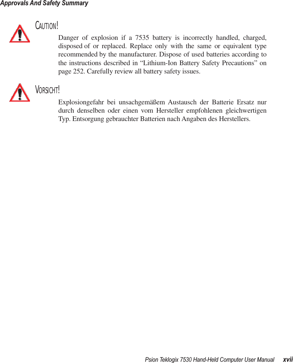
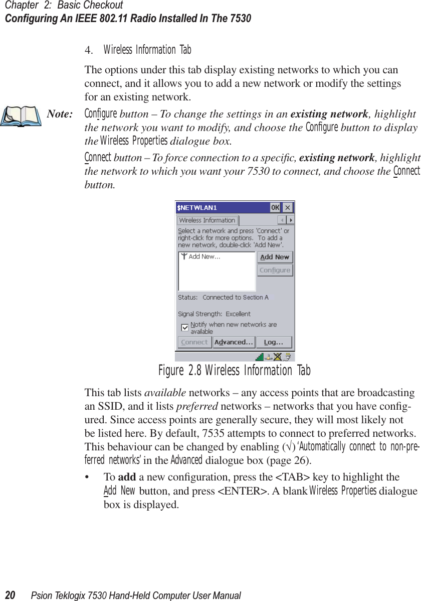
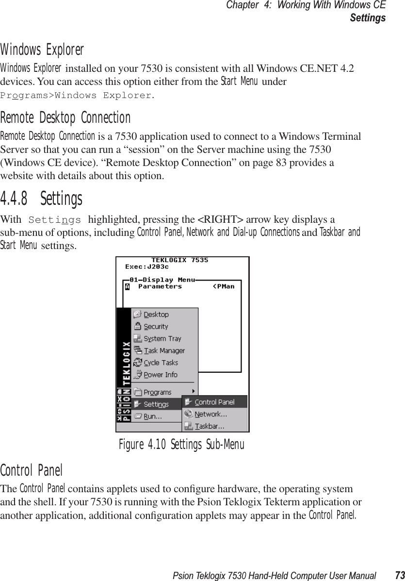
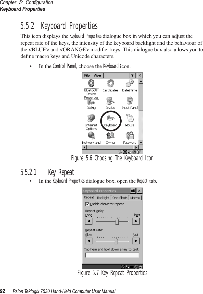
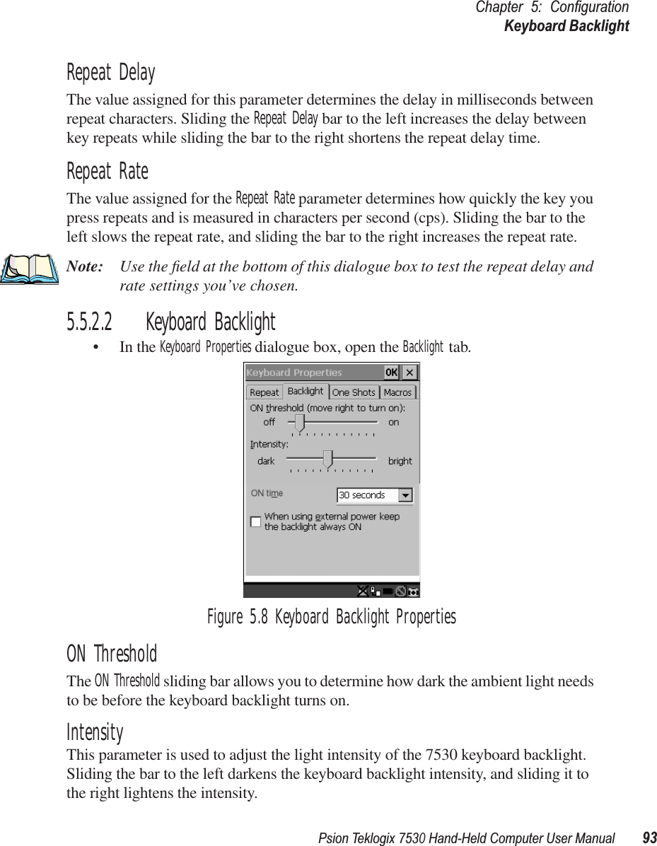
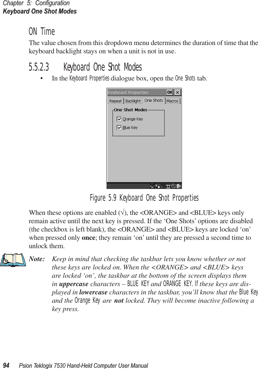
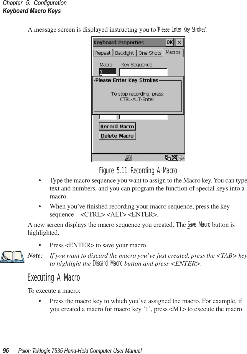
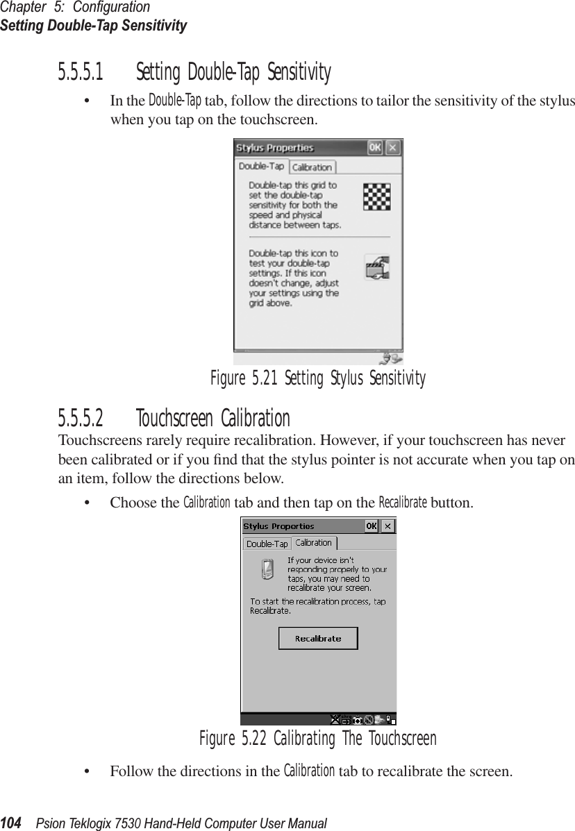
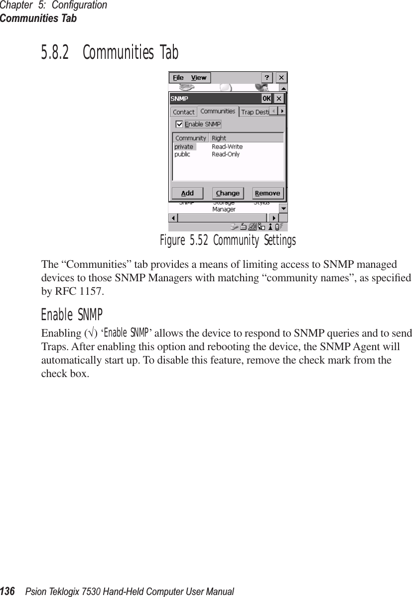
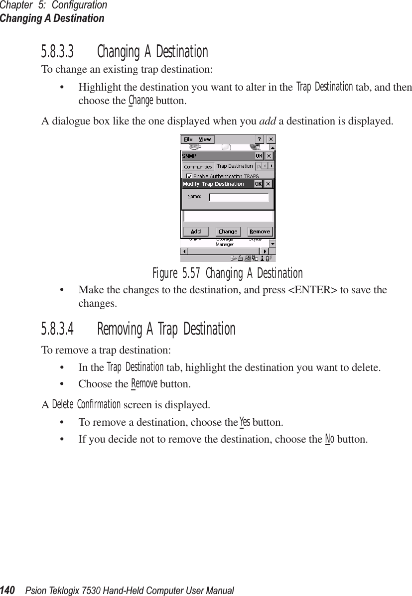
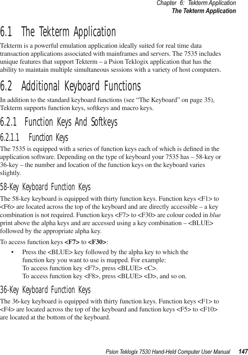
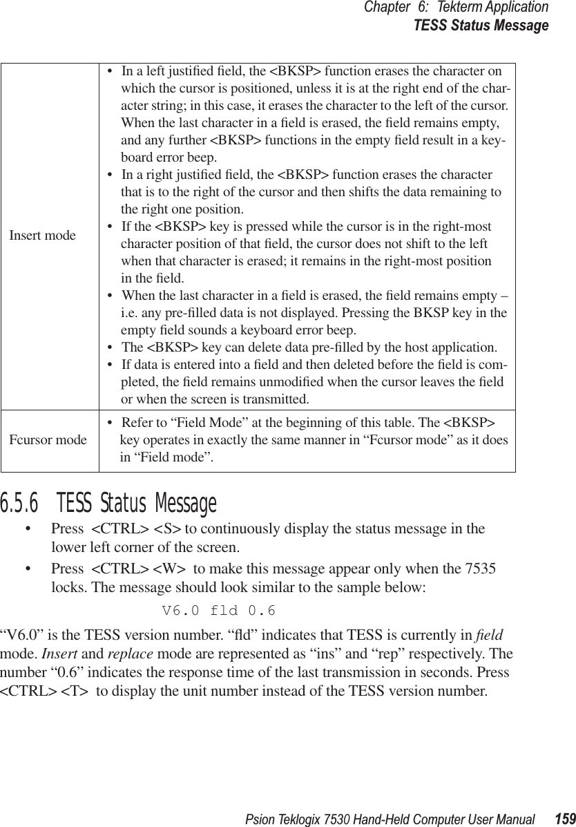
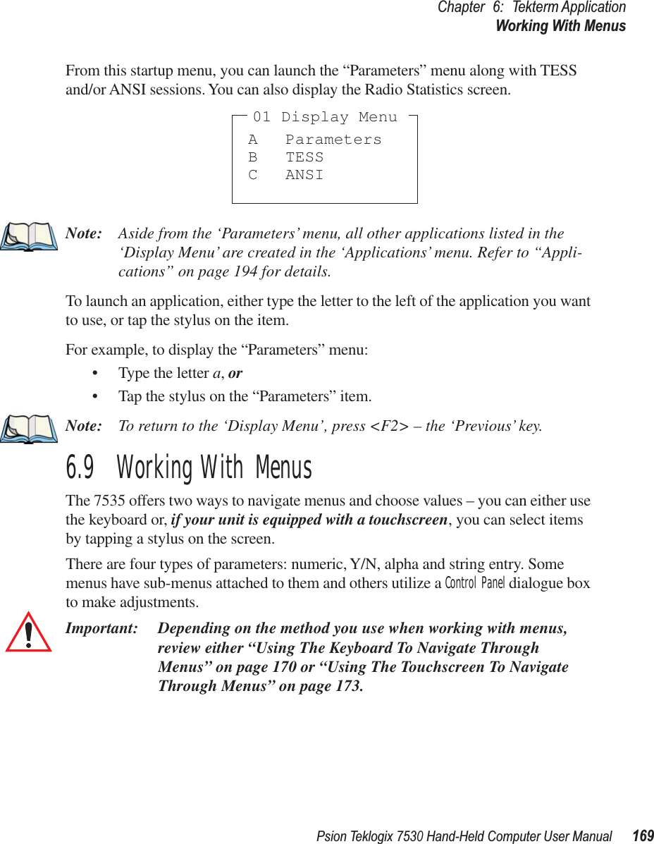
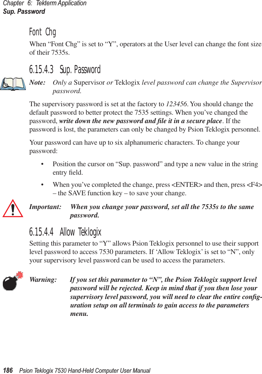
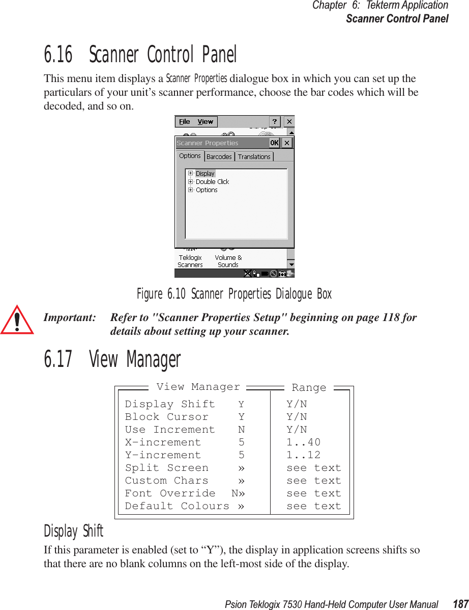
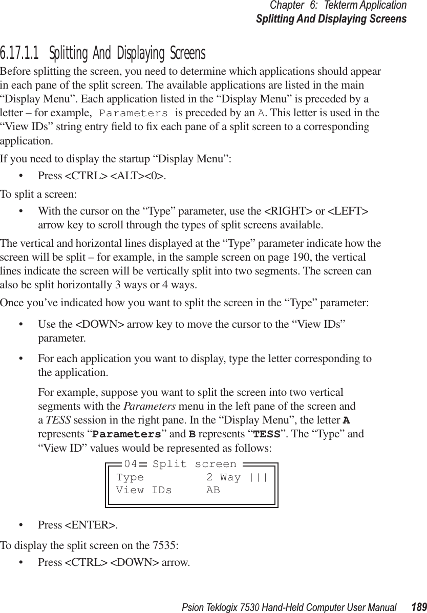
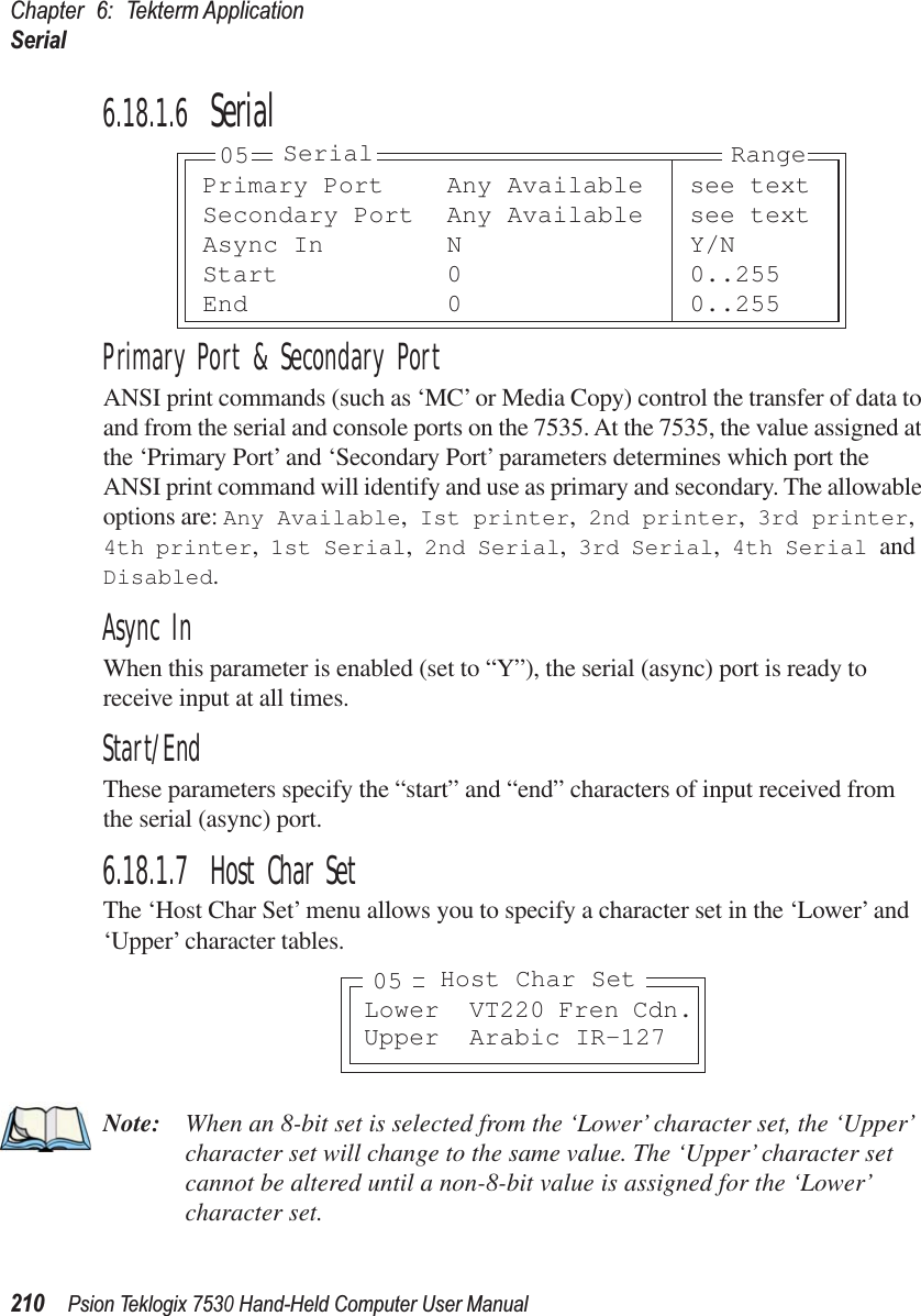
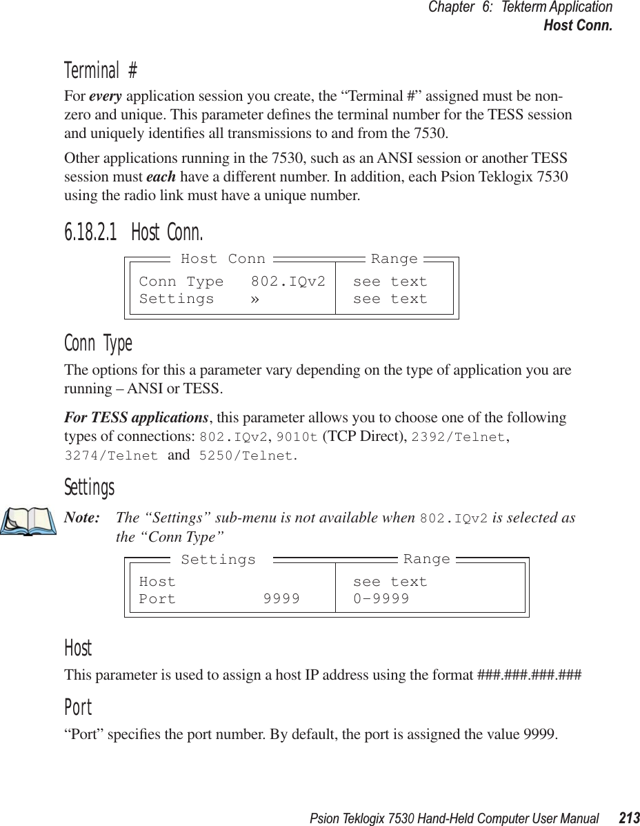
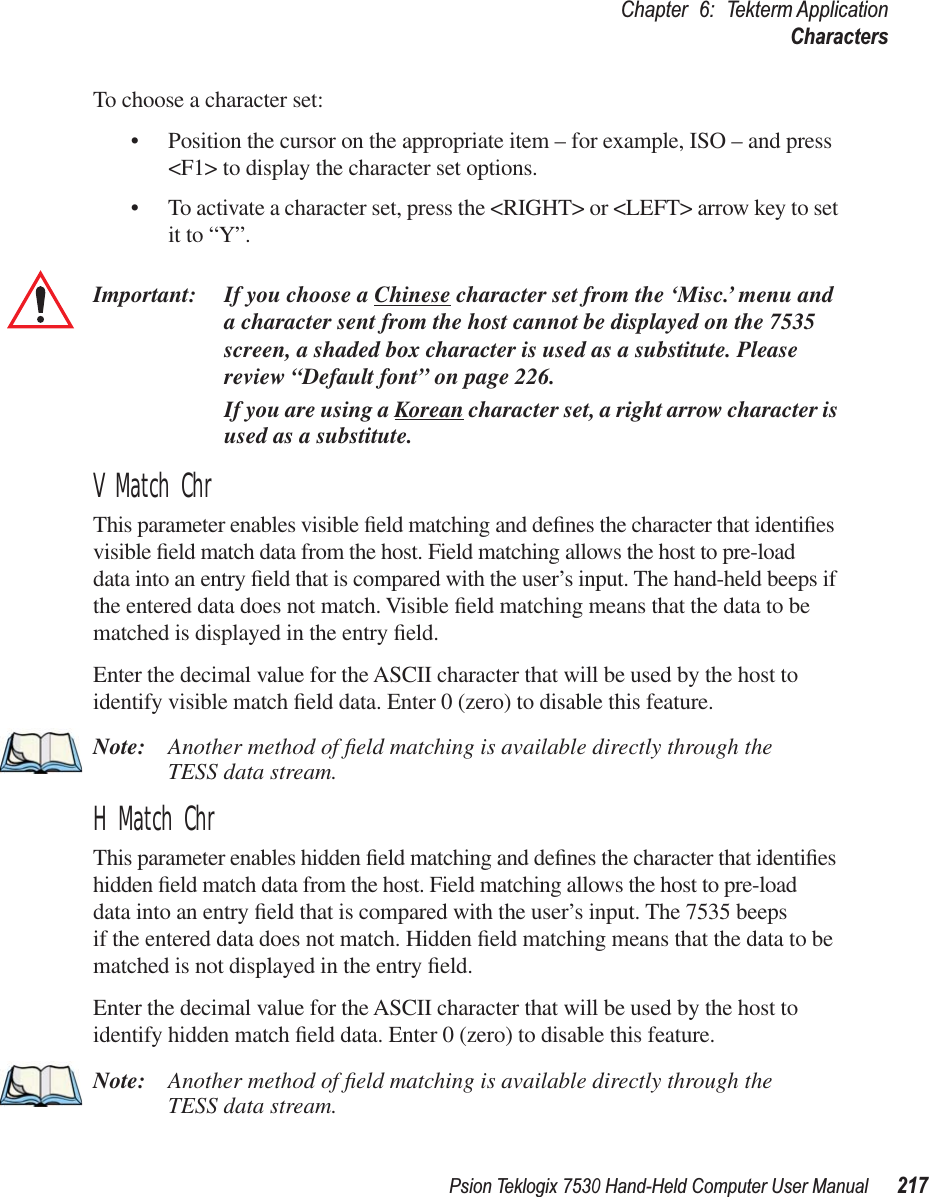
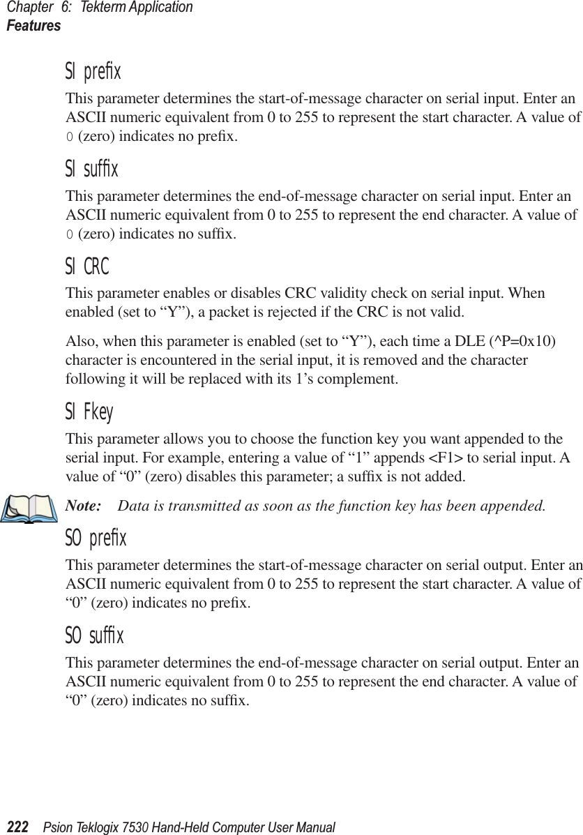
![Psion Teklogix 7535 Hand-Held Computer User Manual 233Chapter 6: Tekterm ApplicationEmulationRemap Underline ToThis parameter allows you to remap the underline cursor to: blink, bold or reverse.Intl EBCDICIf this parameter is enabled (set to ‘Y’), the ‘international’ EBCDIC character set is used, swapping the positions of the ! and ] characters.Nulls In FieldsSetting this parameter to ‘Y’ allows ‘null’ characters – e.g., hyphens (-) or periods (.) – to fill in empty entry fields.Term TypeThe value assigned for this parameter – IBM-5555-001 or IBM-5251-11 – indicates the type of terminal to report during the Telnet negotiations. It determines how the AS/400 host treats the terminal. IBM-5251-11 is a standard 5250 terminal. IBM-5555-001 is a Korean language terminal.Virtual Dev EnabledIf enabled (set to ‘Y’), this parameter allows the 7530 to negotiate a specific device name for itself.Virtual Dev PrefixThe prefix assigned in this field is used when the “Virtual Dev Enabled” parameter (see above) is set to ‘Y’. The current terminal number is appended to the prefix to generate a unique device name. You can assign up to 10 upper-case alphanumeric characters in this field.](https://usermanual.wiki/Psion/7530RA2040/User-Guide-622286-Page-251.png)