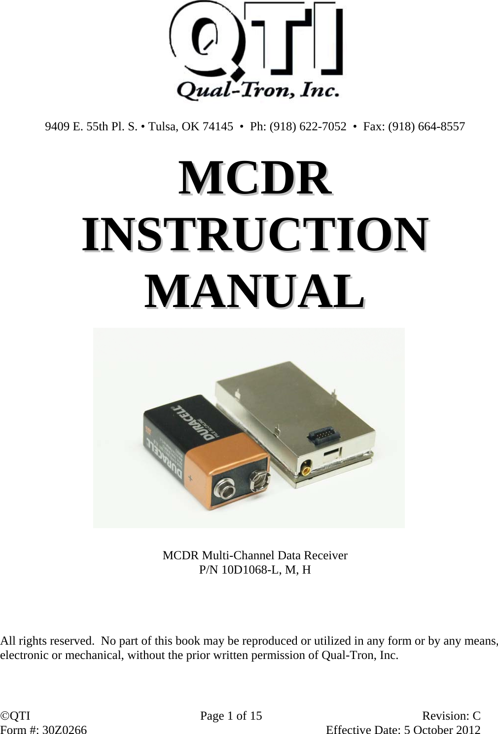
Qual Tron QTIMIDSLBMCDR MODULAR RECEIVER User Manual 30Z0266 MCDRx
Qual-Tron, Inc. MODULAR RECEIVER 30Z0266 MCDRx
UserManual.wiki
>
Qual Tron
>
QTIMIDSLBMCDR User Manual
User Manual
Navigation menu
Upload a User Manual
Namespaces
Wiki Guide
HTML
PDF
Info
Views
User Manual
Discussion / Help
Navigation
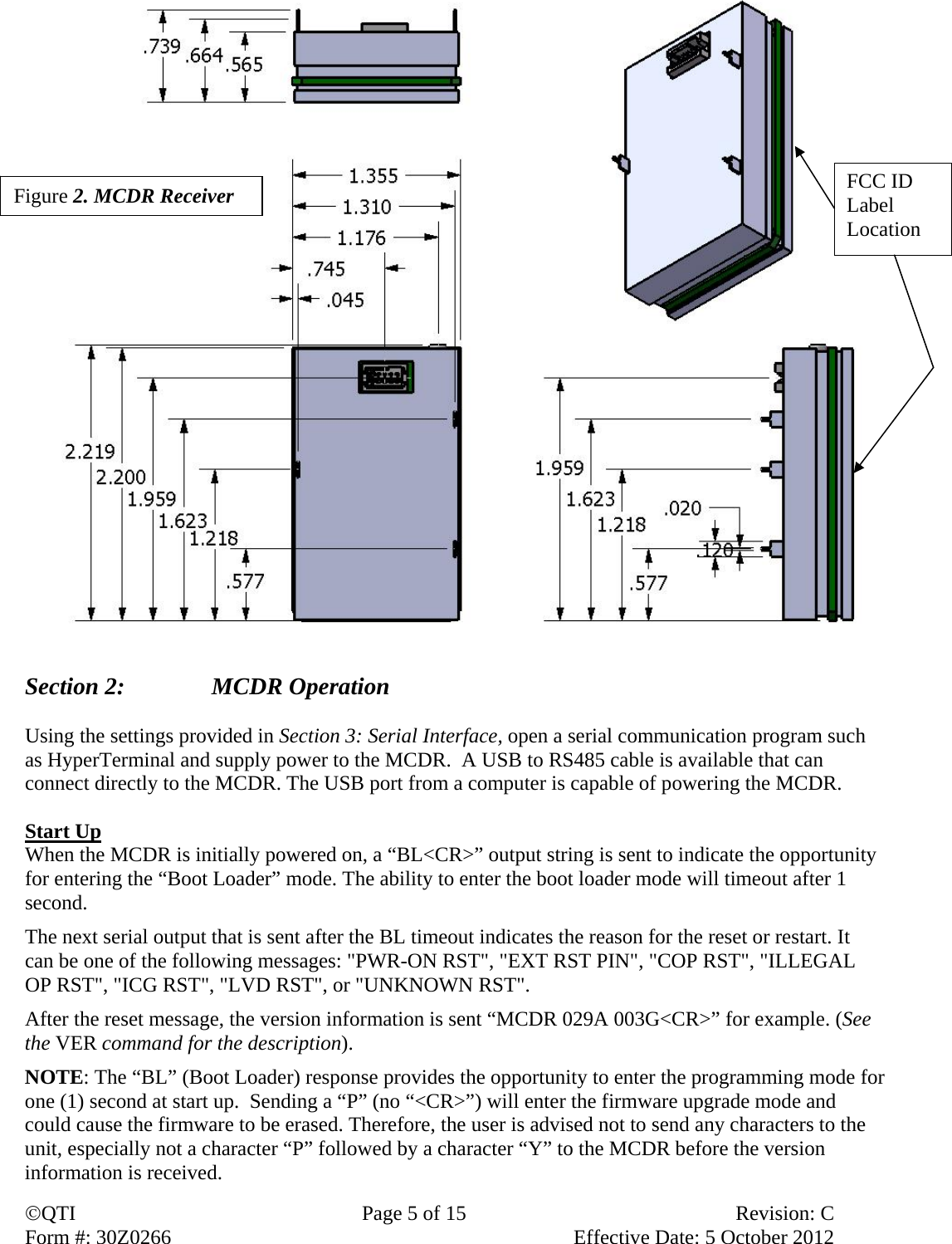
![QTI Page 3 of 15 Revision: C Form #: 30Z0266 Effective Date: 5 October 2012 Section 1: MCDR Multi-Channel Data Receiver Description The Multi-Channel Data Receiver (MCDR) is an OEM modular modem for users who need low power and small size with serial communications. The MCDR is a smaller version of the MCDT-R and is fully compatible. The MCDR is equipped with a RS-485 communications port which is a simple, low-cost interface, utilizing few components and allows for daisy-chaining multiple receivers. The MCDR is capable of receiving SEIWG-005 data messages, which includes a distinct ID and a status code, over a selectable frequency range. This frequency is selectable via the synthesizer control circuit, providing a selection of up to 1920 RF channels, depending on the model’s frequency range. The MCDR comes in Low-Band, Mid-Band, and High-Band models, having the following frequency ranges: Low Band Medium Band High Band Channel 001 = 138.025 MHz Channel 001 = 154.005 MHz Channel 001 = 162.00625 MHz Channel 640 = 154.000 MHz Channel 1600 = 162.000 MHz Channel 1920 = 174.000 MHz Channel Spacing: 25 kHz Channel Spacing: 5 kHz Channel Spacing: 6.25 kHz Model Numbers (3 models) 10D1068-L, -M, -H MCDR-L, -M, -H MCDR Receiver only; low, mid, or high band Antenna: MMCX jack 50 ohm (J1) (10D1984 MMCX to TNC 3” cable available) Power Supply: 3.5 VDC to 16.5 VDC Receive Connections: J2 - Header Pin (10-pin TFM-105) MCDR_ Receiver Model 1, 2 Vin [Input] 3.5 to 16.5 VDC 3 Not Used 4 RS485 – B(+) [I/O] 5 RS485 – A(-) [I/O] 6 Same as pins 1,2 7 General I/O 8, 9, 10 GND MCDR Receiver](https://usermanual.wiki/Qual-Tron/QTIMIDSLBMCDR/User-Guide-1915389-Page-3.png)
![QTI Page 7 of 15 Revision: C Form #: 30Z0266 Effective Date: 5 October 2012 processor. Once awake the user can poll to get the new message. See the NEW command. If the MCDR is still awake and the MCDR receives a new message, the shut-down mode will not occur until the RS485 serial ID has been sent and acknowledged. The user’s application must respond or an infinite loop condition would occur causing the MCDR to never shut down. The MCDR communicates over RS-485. Commands must be followed by a carriage return (<CR>). Settings are retained only until power is turned off unless the SAV command is used to store them to the unit’s flash memory. When sending commands and queries, a two-digit hexadecimal checksum (cs) can be used to check data integrity. Refer to the Checksum section after the Command List. SETTINGS 38400 baud [fixed], No parity, 8 bit, 1 stop bit, No flow control Message Serial Format Decoded message is sent via RS-485: RXM TT III SS R<CR> - Received message TT = Message Type, III = ID code, and SS = status code; TT and SS are hexadecimal, and III is decimal. R is the receive signal strength indicator; see RSS command. Example: RXM 0D 244 0B Message received – Received message type “EMIDS” with an ID code of 244 and a status code of TEST, FAULT. MESSAGE TYPE (TT) The message type consists of two (2) hexadecimal characters. The first character shows the parity; the most significant bit will be set if the parity is bad. The second character identifies the type. Good Parity Bad Parity MIDS 07h 87h EMIDS 0Dh 8Dh TRSS 1Dh 9Dh REMBASS 06h 86h Message Type Table NOTE: TRSS and REMBASS message formats available upon request.](https://usermanual.wiki/Qual-Tron/QTIMIDSLBMCDR/User-Guide-1915389-Page-7.png)
![QTI Page 9 of 15 Revision: C Form #: 30Z0266 Effective Date: 5 October 2012 MCDR Serial Commands: Note: It is recommended that when using a processor to control the MCDR that the format described under Checksum be used. This format helps ensure data integrity by greatly reducing communication errors and is more robust for machine to machine (M2M) applications. Valid commands will return the command and the argument followed by the word “OK”. Invalid commands return “SYNTAX ERROR”. Invalid command arguments will return “ERR” at the end of the command and argument. Carriage Return represents end of line and causes the line to be processed. If command is given with “#” at the beginning, then a two digit checksum is expected before <CR>. Returned string has a checksum if checksum sent. Checksum is two’s compliment of the command string (everything before checksum). A space is always included between the command and the argument: “CHR <space> 101 <CR>”. Command List ? … Brings up the help menu The current help menu (without checksums) appears as follows: Commands List: HELP/?: Show this menu CHR: Get/Set rcv Chan CMB: Clear message buffer CRF: Get receive channel in Hz M2M: Get/Set Machine to Machine mode MSG: Get rcvd msg NEW: Get new messages PSH: Get/Set push mode RCV: Get/Set receive mode RSS: Get receive signal strength RST: Reset SAV: Save Current Parameters SID: Get/Set the RS485 ID SLP: Enter Sleep mode SRN: Get unit serial num TMP: Read Temp VER: Show versions CHR… Get/Set the receive channel. (Follow with SAV command.) Z is the channel number, [1 = DEFAULT]: Low Band 0-600; Mid Band 0-1600; High Band 0-1920 Get the channel: CHR<CR> Returns: CHR Z<CR> Set the channel: CHR Z<CR> Returns: CHR Z OK<CR> Invalid returns: CHR Z ERR<CR> CMB… Clear Message Buffer; see MSG command. Get the frequency: CMB<CR> Returns: CMB OK<CR>](https://usermanual.wiki/Qual-Tron/QTIMIDSLBMCDR/User-Guide-1915389-Page-9.png)
![QTI Page 10 of 15 Revision: C Form #: 30Z0266 Effective Date: 5 October 2012 CRF… Get the receive channel as a frequency in Hz. (138000000-174000000) Get the frequency: CRF<CR> Returns: CRF Z<CR> M2M…Get/Set machine to machine mode (follow with SAV command). In machine to machine mode all returned messages begin with ‘#’ and end with the checksum before the <CR>. Commands can be issued without ‘#’ and a checksum. No syntax errors are reported for unknown commands. Z = 0: OFF Z = 1: ON [DEFAULT] Get M2M mode: M2M<CR> Returns: M2M Z<CR> Set M2M mode: M2M Z<CR> Returns: M2M Z OK<CR> Invalid returns: M2M Z ERR<CR> MSG… Recall a previous message. Z (decimal 0-9) is the message with 0 being most recent message and 9 being the oldest message. If the requested message is empty, all the fields will return with zeros. Returned values: TT (hexadecimal) is the message type, III (decimal) is the ID, SS (hexadecimal) is the status code, and R (decimal) is the RSSI. (See RSS command.) Get a message: MSG Z<CR> Returns: RXM TT III SS R<CR> Invalid returns: MSG Z ERR<CR> NEW… Read New messages. Use when PUSH is OFF. This returns the oldest unread message. Send “NEW 1” to mark the message as read, so it will no longer be returned with the “NEW” command. Note: This command can also be used if the PUSH is enabled. Returned values: TT (hexadecimal) is the message type, III (decimal) is the ID, SS (hexadecimal) is the status code, and R (decimal) is the RSSI. Poll for a new message: NEW<CR> Returns: RXM TT III SS R<CR> If no new message Returns: RXM<CR> Mark message as read: NEW 1<CR> Returns: NEW 1 OK<CR> PSH… Get/Set to push new messages out the serial port. Z = 2: ON (Pushes <CR><CR> prior to sending the new message) Version 0.2.8.A and above. Z = 1: ON (New messages are pushed out the serial port when received.) [DEFAULT] Z = 0: OFF (Master must poll for new messages – Receiver sends RS485 ID on receipt of new message when in power-down mode). Get PUSH mode: PSH<CR> Returns: PSH Z<CR> Set PUSH mode: PSH Z<CR>](https://usermanual.wiki/Qual-Tron/QTIMIDSLBMCDR/User-Guide-1915389-Page-10.png)
![QTI Page 11 of 15 Revision: C Form #: 30Z0266 Effective Date: 5 October 2012 Returns: PSH Z OK<CR> Invalid returns: PSH Z ERR<CR> RCV…Get/Set receive mode. Z = 1: ON (receiver enabled) [DEFAULT]; CAUTION: If no receiver has been installed, the receiver should be disabled to conserve power. Z = 0: OFF (receiver disabled) Get receive mode: RCV<CR> Returns: RCV Z<CR> Set receive mode: RCV Z<CR> Returns: RCV Z OK<CR> Invalid returns: RCV Z ERR<CR> RSS… Get the receive signal strength indicator (RSSI). Returns a positive decimal number (0-9), where higher numbers indicate stronger signal. Good signal strength is 6+. If receiver is disabled, it returns 0 (min). Note: This command immediately reads the RSSI value, which is useful to determine if a frequency is being used or jammed. The “MSG” command appends the RSSI value that occurred while receiving the message, which is useful in site selection and deployment. Get RSSI: RSS<CR> Returns: RSS R<CR> RST… Reset the unit. On start-up the MCDT outputs version. Reset the unit: RST<CR> Returns: RST OK<CR> SAV… Save the current parameters in flash memory. Use this to store any parameter changes. Save current settings: SAV<CR> Returns: SAV OK MCDT<CR> SID… Get/Set the RS-485 serial identifier. [T = DEFAULT] Capital character (A-Z). All MCDT’s will respond to X so it should not be used. The purpose and use of this command is described below in Checksum. Get protection: SID<CR> Returns: SID Z<CR> Set protection: SID Z<CR> Returns: SID Z OK<CR> Invalid returns: SID Z ERR<CR> SLP… Shut down the serial port to conserve power. The MCDT goes to power-down mode immediately after returning the SLP OK command. Note: To reactivate the serial port, send a carriage return or some other ASCII character. Use “SLP 0” when RS-485 bus is shared. Enter low power mode: SLP<CR> Returns: SLP OK<CR> Enter low power mode: SLP 0<CR> Returns: <Nothing returned>](https://usermanual.wiki/Qual-Tron/QTIMIDSLBMCDR/User-Guide-1915389-Page-11.png)
![QTI Page 12 of 15 Revision: C Form #: 30Z0266 Effective Date: 5 October 2012 SRN… Get the unit serial number. The serial number is a string up to 8 characters long. Get serial number: SRN<CR> Returns: SRN Z<CR> TMP… Get the board temperature in degrees Celsius (decimal), with a tenth degree precision (250 = 25.0C). Get temperature: TMP<CR> Returns: TMP Z<CR> VER… Get the unit version. MCDR is the model, <space>, VVVV is the firmware version (Major.Minor.Build.Rev), <space>, M is the message types supported (0 = standard [MIDS/EMIDS], 1 = custom), B is the frequency band (0 = low, 1 = mid, 2 = high), H is the hardware capabilities (1 = receive only, 2 = transmit only, 3 = both), R is the hardware board revision. Get version: VER<CR> Returns: MCDR VVVV MBHR<CR> Checksum To use checksum begin the command with “#” plus the unit serial ID and end the command with the calculated checksum (cs) value followed by the carriage return <CR>. A command with an invalid checksum or invalid serial ID is ignored and no reply is sent. The checksum is a 2 digit hexadecimal calculated as the 2’s compliment of the sum of the command string including the “#” and serial ID. Using the checksum also allows and requires using the serial ID. The universal serial ID is X, so all units will acknowledge these commands. The unit will respond with its specific serial ID. Sample syntax: Action With Checksum Without Checksum Get receive channel: #XCHRA8<CR> CHR<CR> Returns: #ACHR 196FF<CR> CHR 196<CR> Set receive channel to 2: #XCHR 256<CR> CHR 2<CR> Returns: #ACHR 2 OKB3<CR> CHR 2<CR> Note: “A” is just a sample serial ID, and may be different. Example checksum C-Code calculator char CRC2sComp( char *buffr, int end) { //creates 2's complement int c; int calcSum = 0; for( c = 0; c <= end; c ++ ) { calcSum += buffr[c]; } calcSum ^= 0xFF; //1's complement calcSum += 1; //now 2's complement return (char)(calcSum); }](https://usermanual.wiki/Qual-Tron/QTIMIDSLBMCDR/User-Guide-1915389-Page-12.png)
![QTI Page 13 of 15 Revision: C Form #: 30Z0266 Effective Date: 5 October 2012 Example Checksum Line to send is “#ACHR 597<CR>” Convert characters to ASCII values: # (35) + A (65) + C (67) + H (72) + R (82) + <sp> (32) + 5 (53) + 9 (57) + 7 (55) NOTE: <CR> is not included in calculation. Sum: 35+65+67+72+82+32+53+57+55 = 518T (206h) 1’s Complement is bit inversion: = [10 0000 0110] [01 1111 1001] = 1F9h 2’s complement is adding 1 to the 1’s complement: 1F9 + 1 = 1FAh Drop anything higher than the lowest 8 bits: [1 1111 1010] [1111 1010] = FAh The result is FAh, so send line as “#ACHR 597FA<CR>” Note: Adding the checksum will result in zero for the low byte. (206h + FAh = 300h)](https://usermanual.wiki/Qual-Tron/QTIMIDSLBMCDR/User-Guide-1915389-Page-13.png)