RF Controls IN610 RF ID Interrogator User Manual Users Guide 610
RF Controls, LLC RF ID Interrogator Users Guide 610
UserManual.wiki
>
RF Controls
>
IN610 User Manual
>
Users_Guide 610
Contents
1.
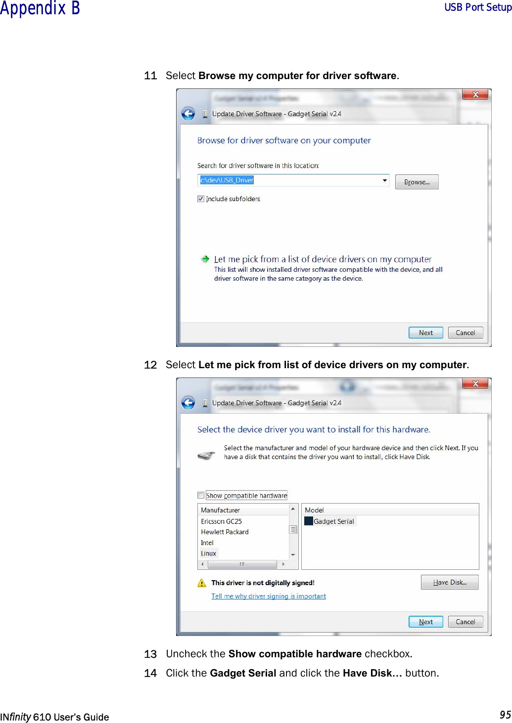
Users_Guide 610
2.
Users_Guide A-200 and A-202
Users_Guide 610
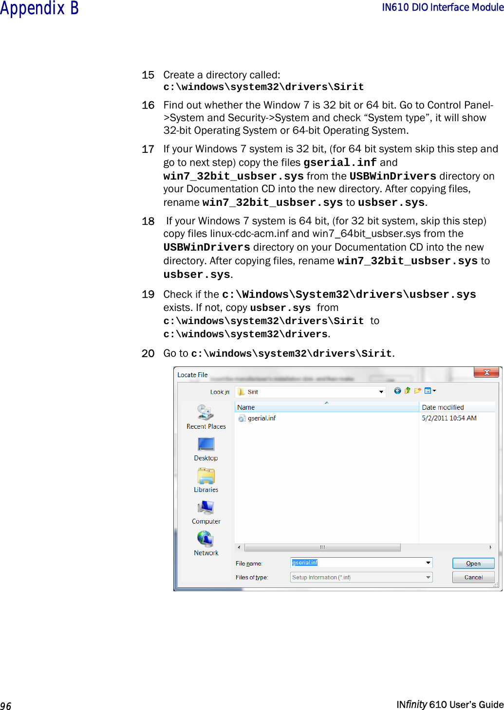
Navigation menu
Upload a User Manual
Namespaces
Wiki Guide
HTML
PDF
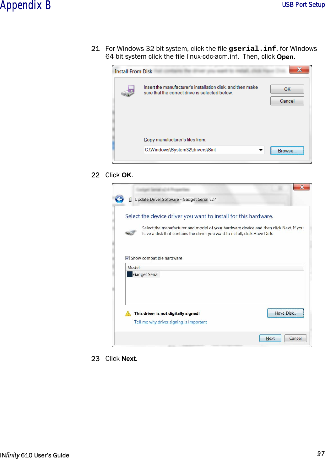
Info
Views
User Manual
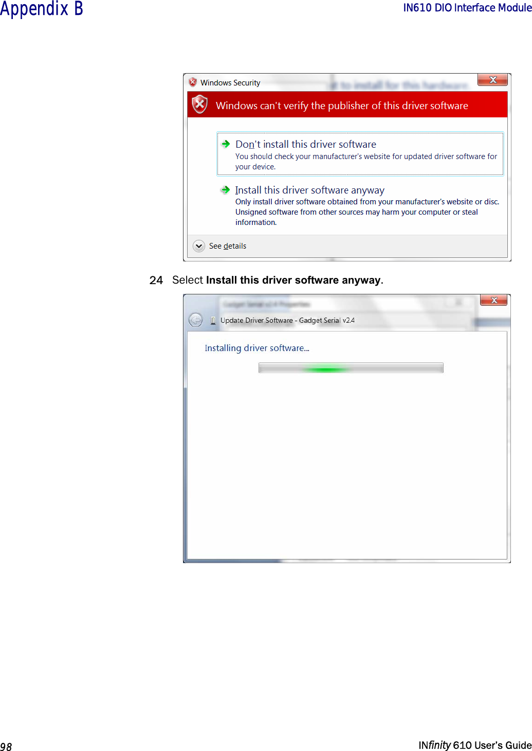
Discussion / Help
Navigation


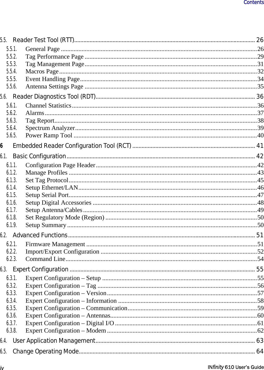
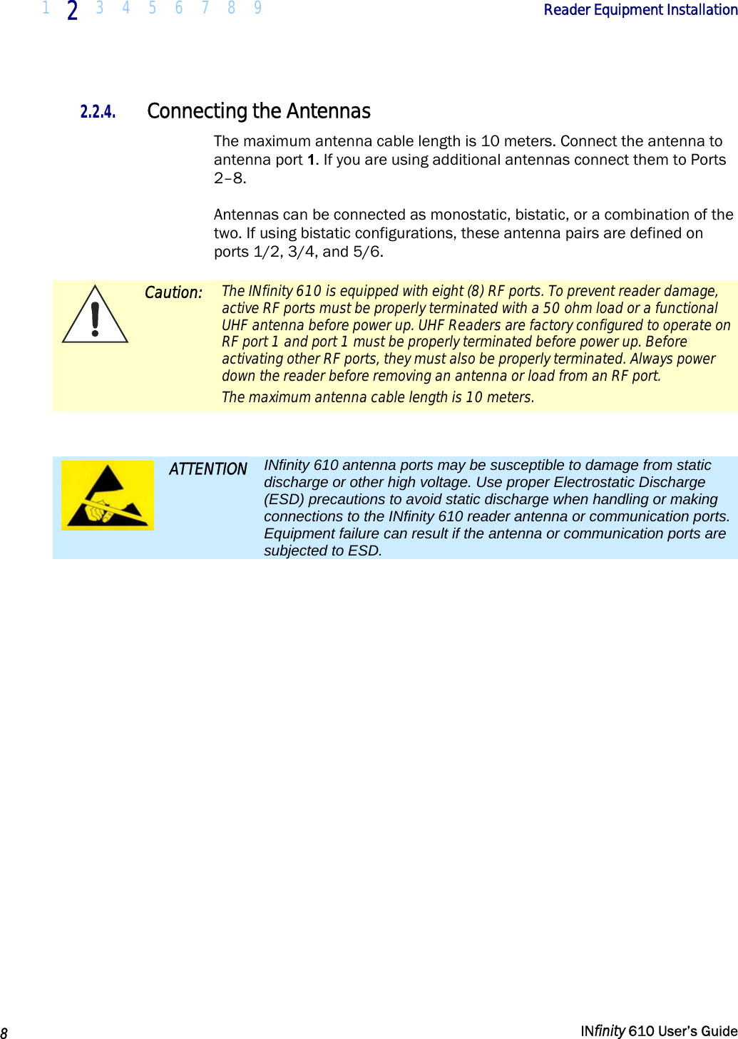
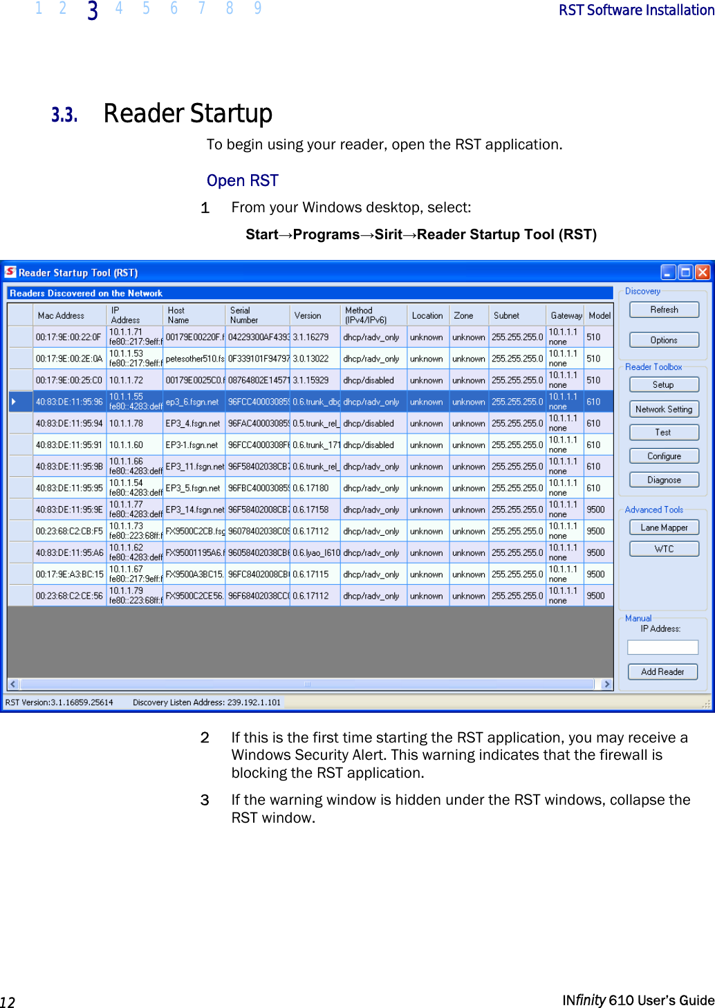
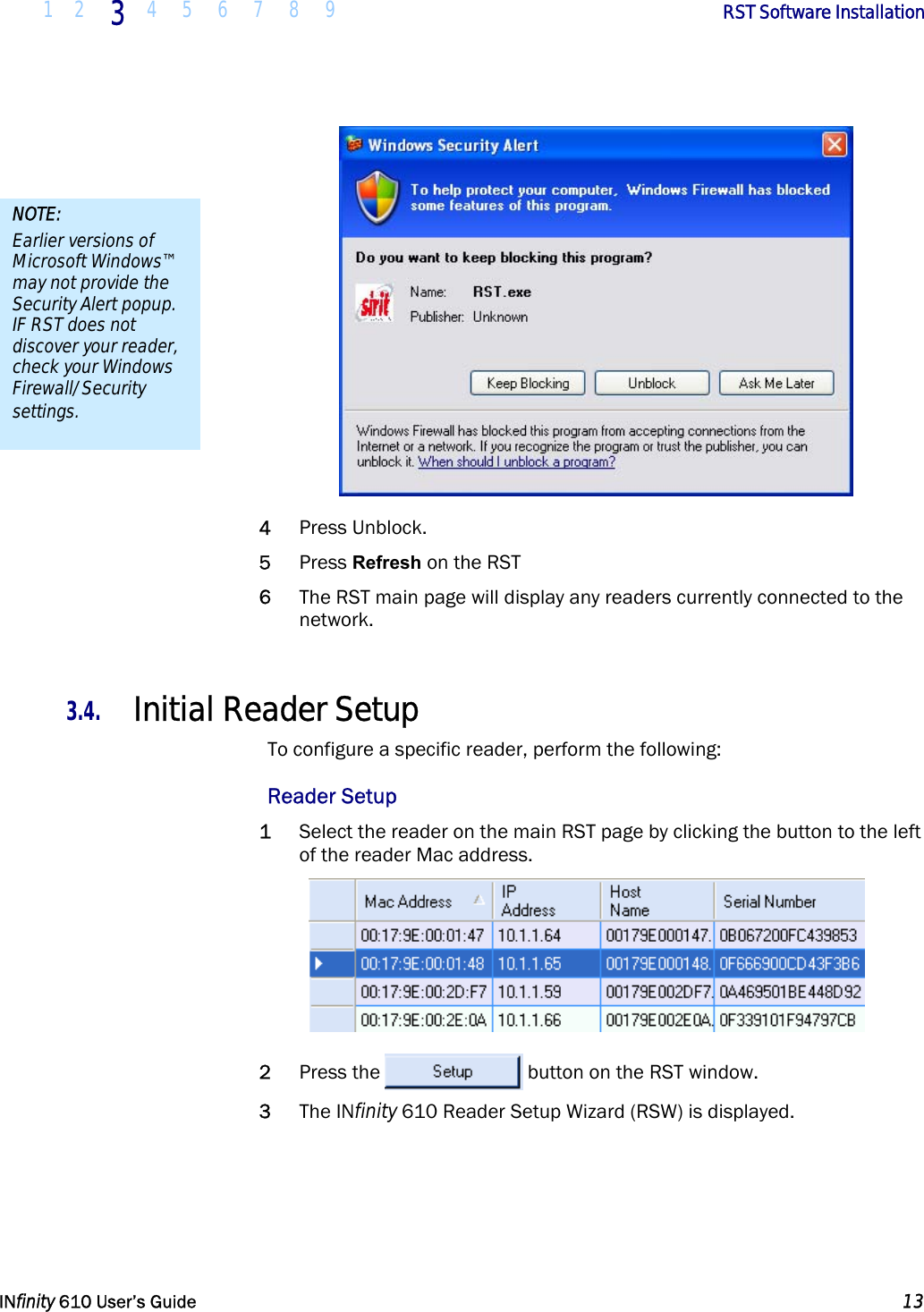
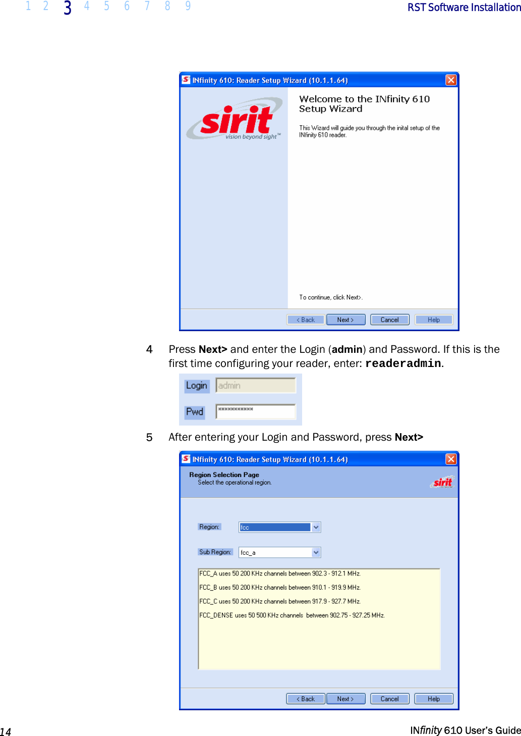
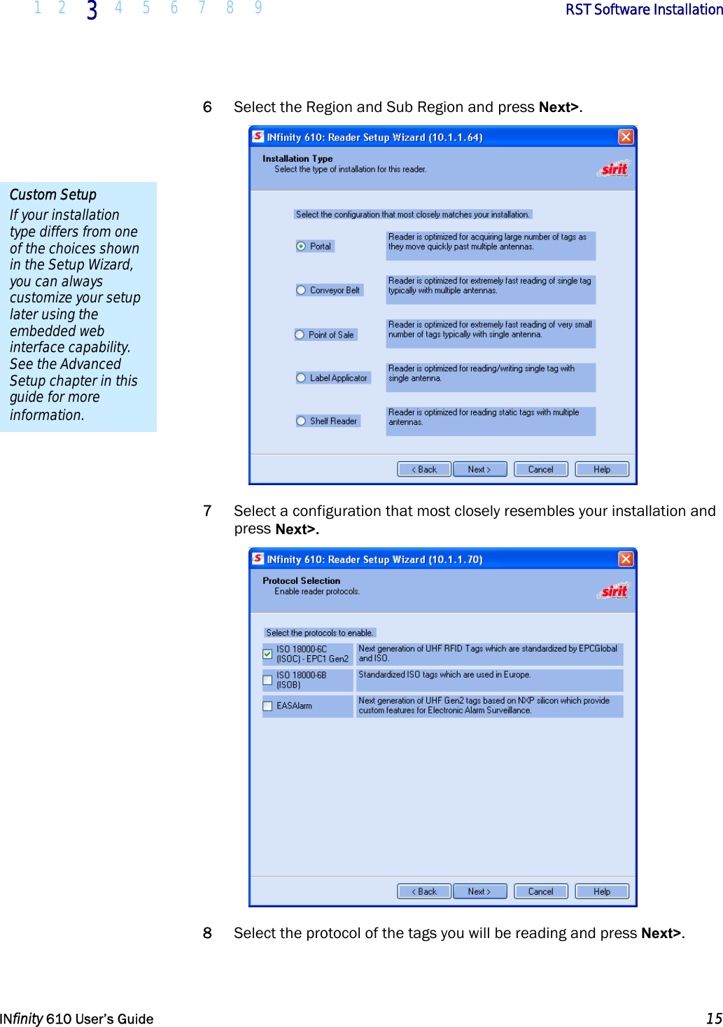
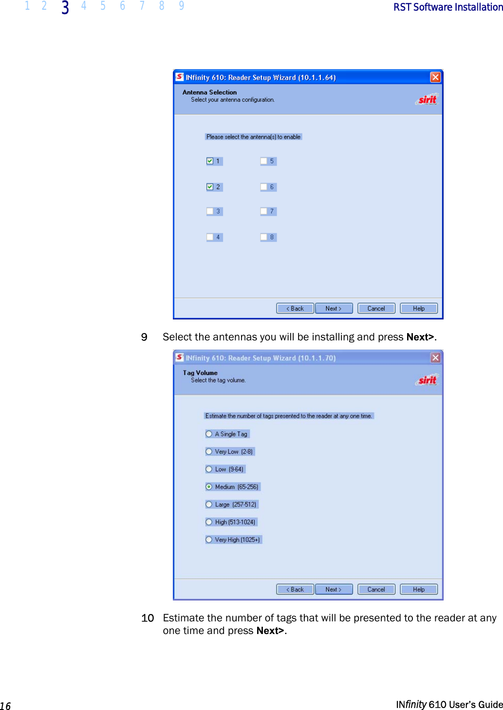
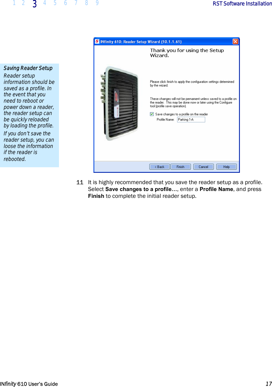
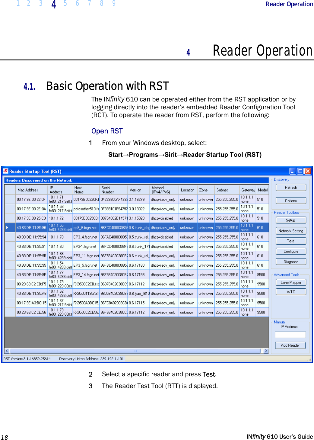
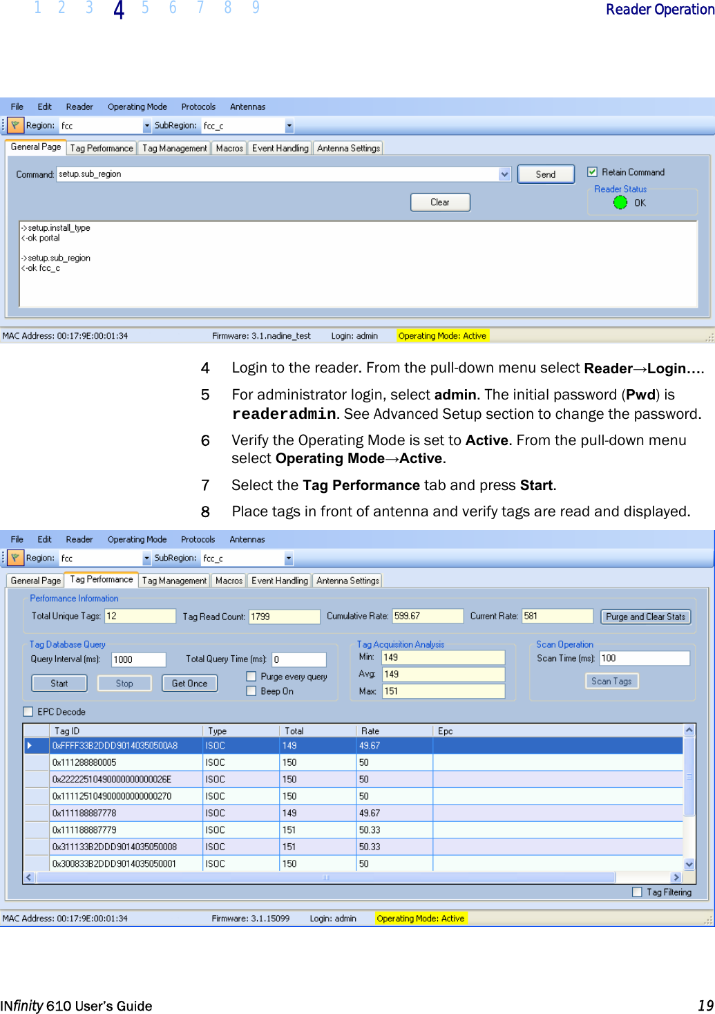

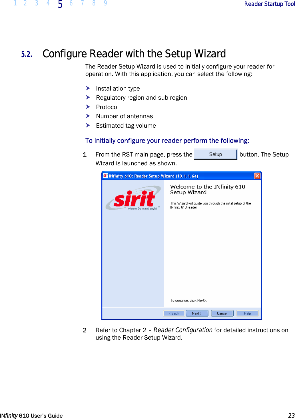
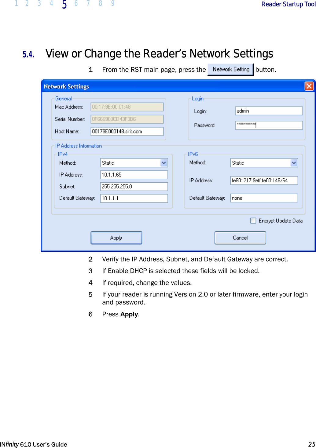
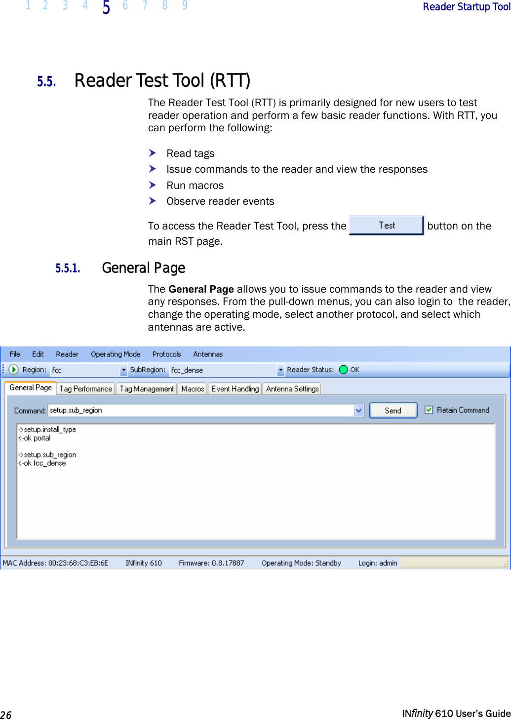
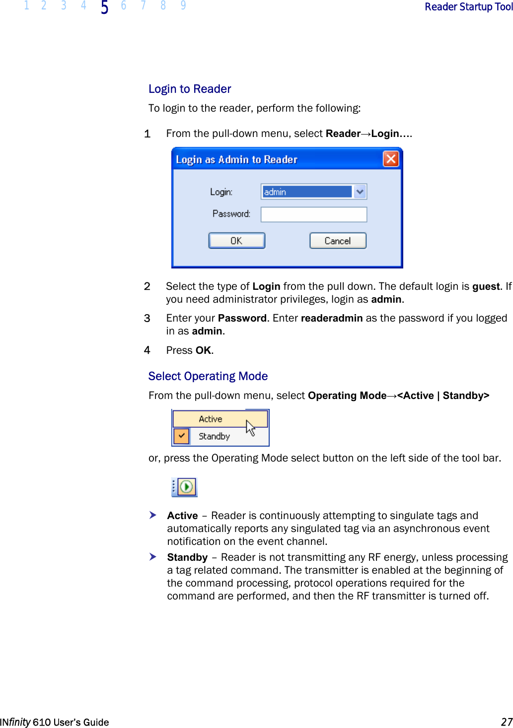
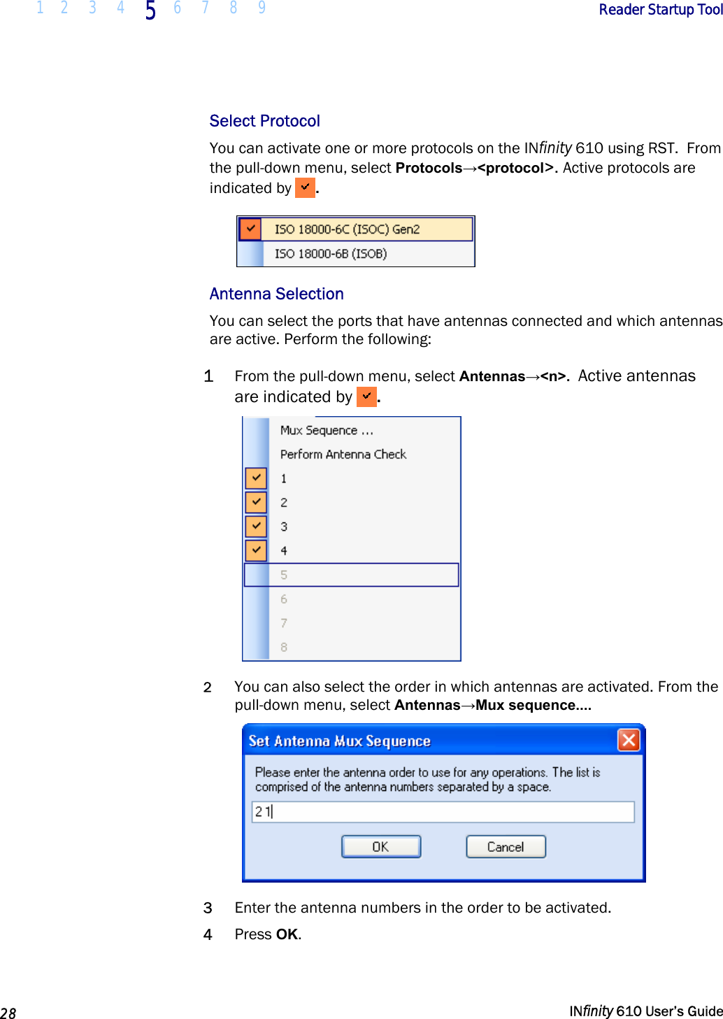
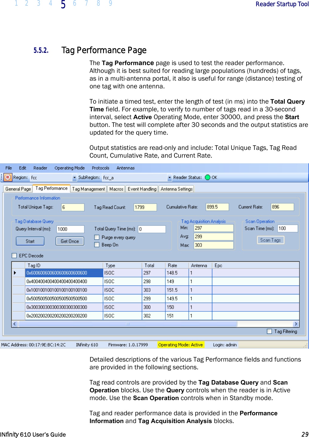
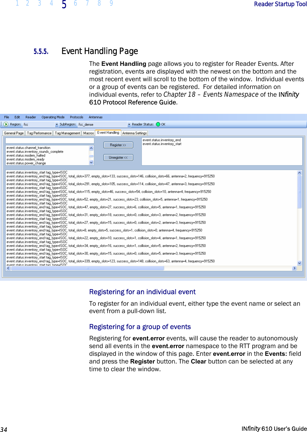
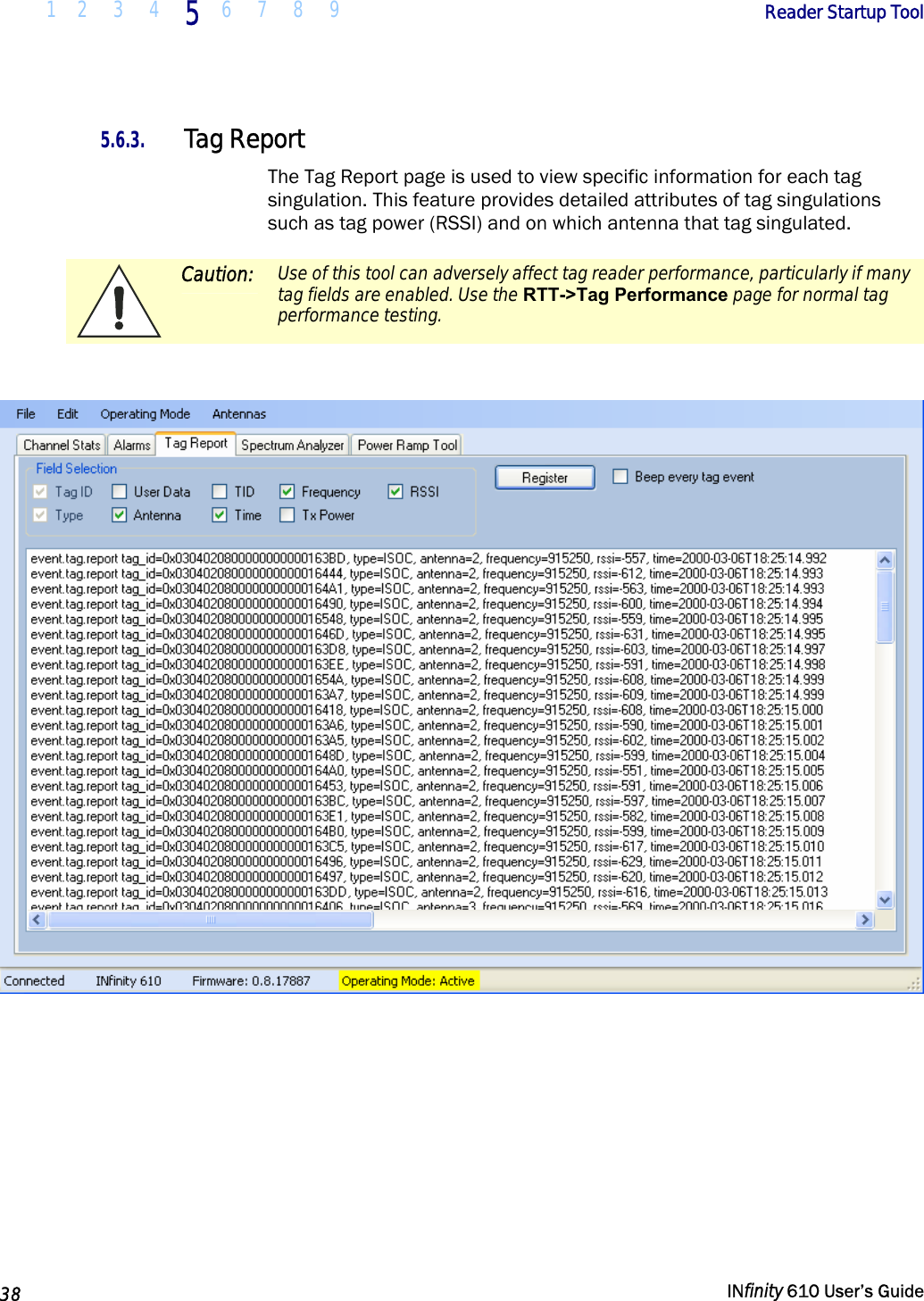
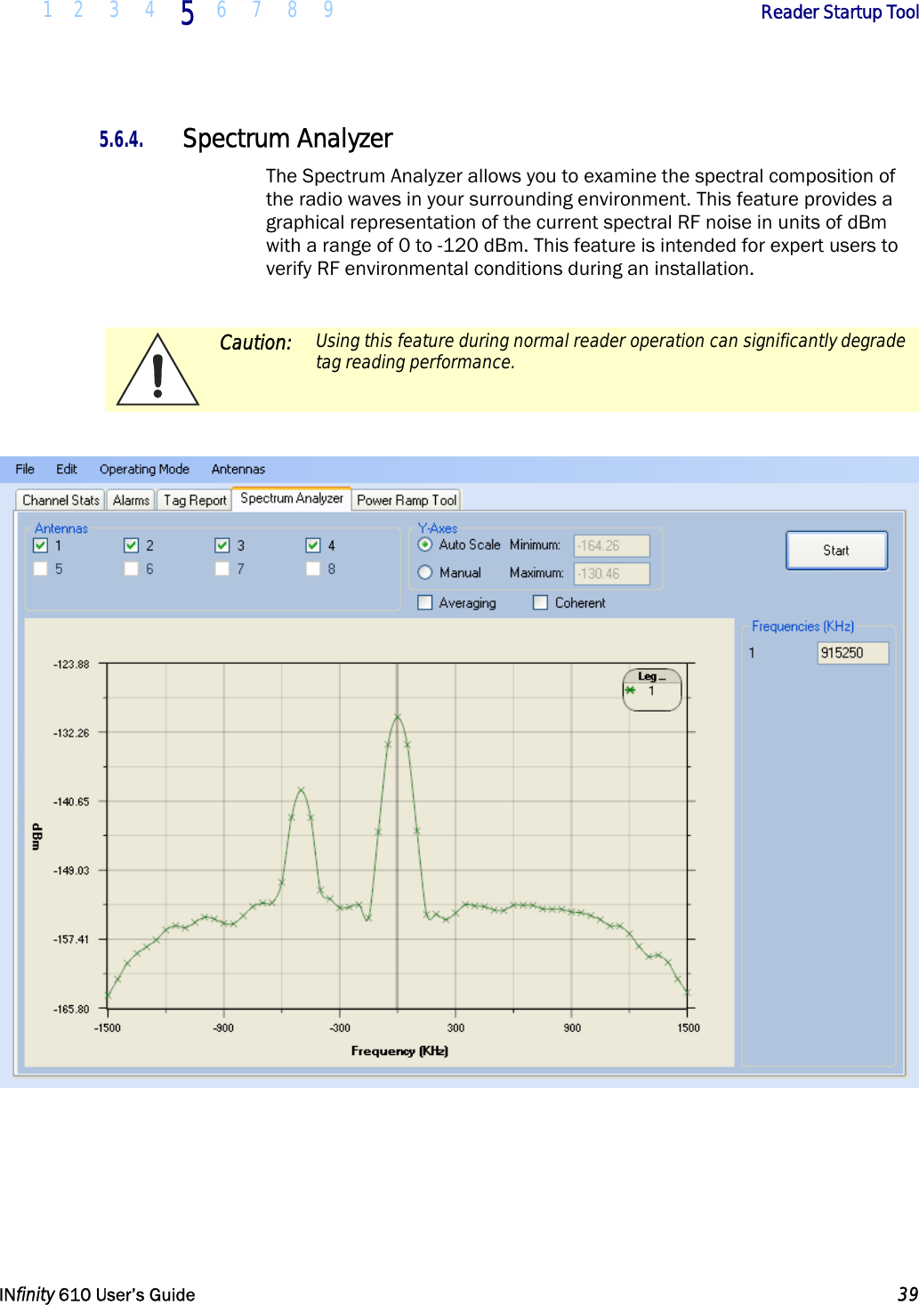
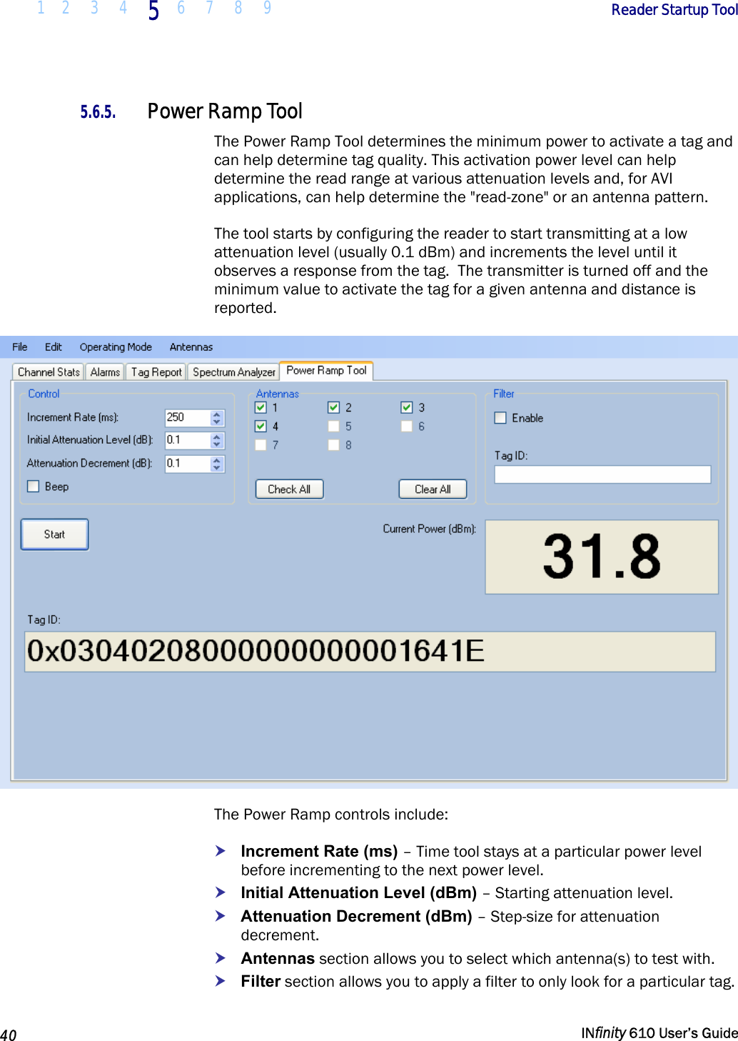
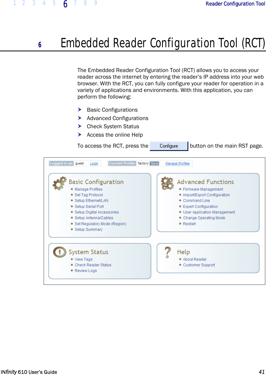
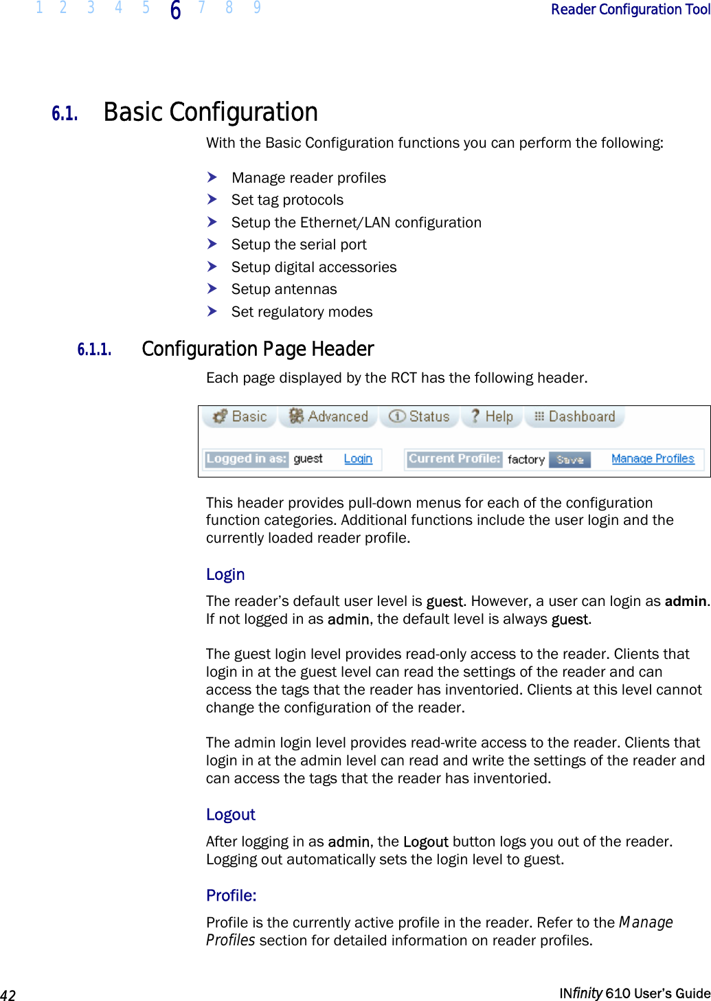
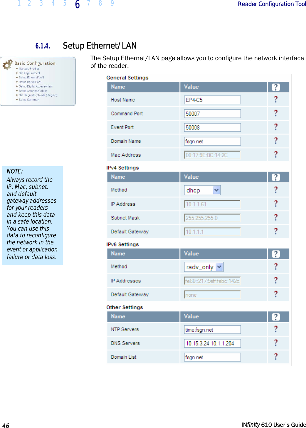
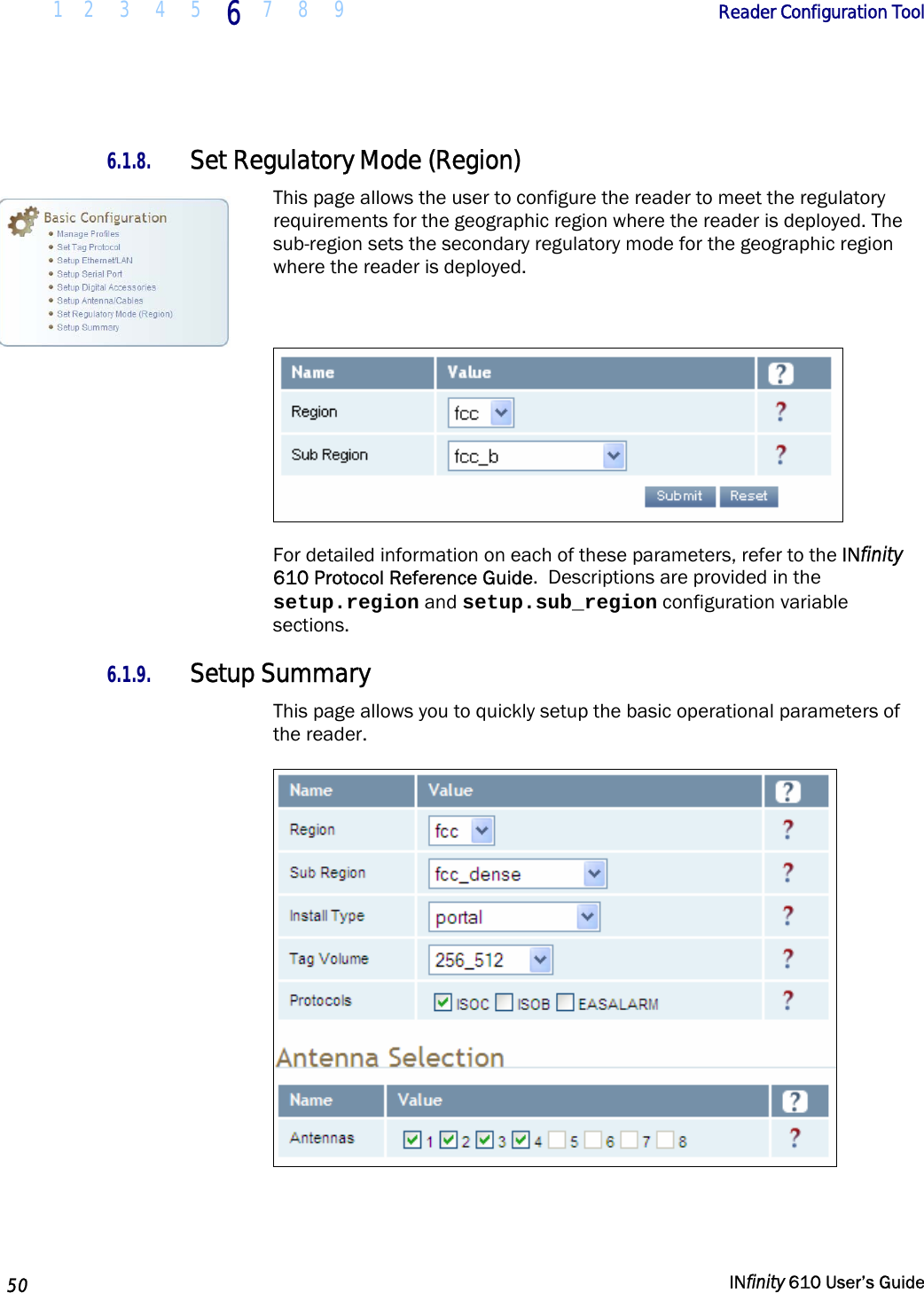
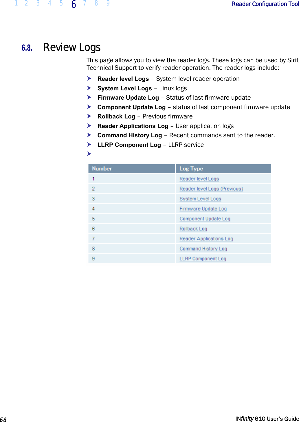
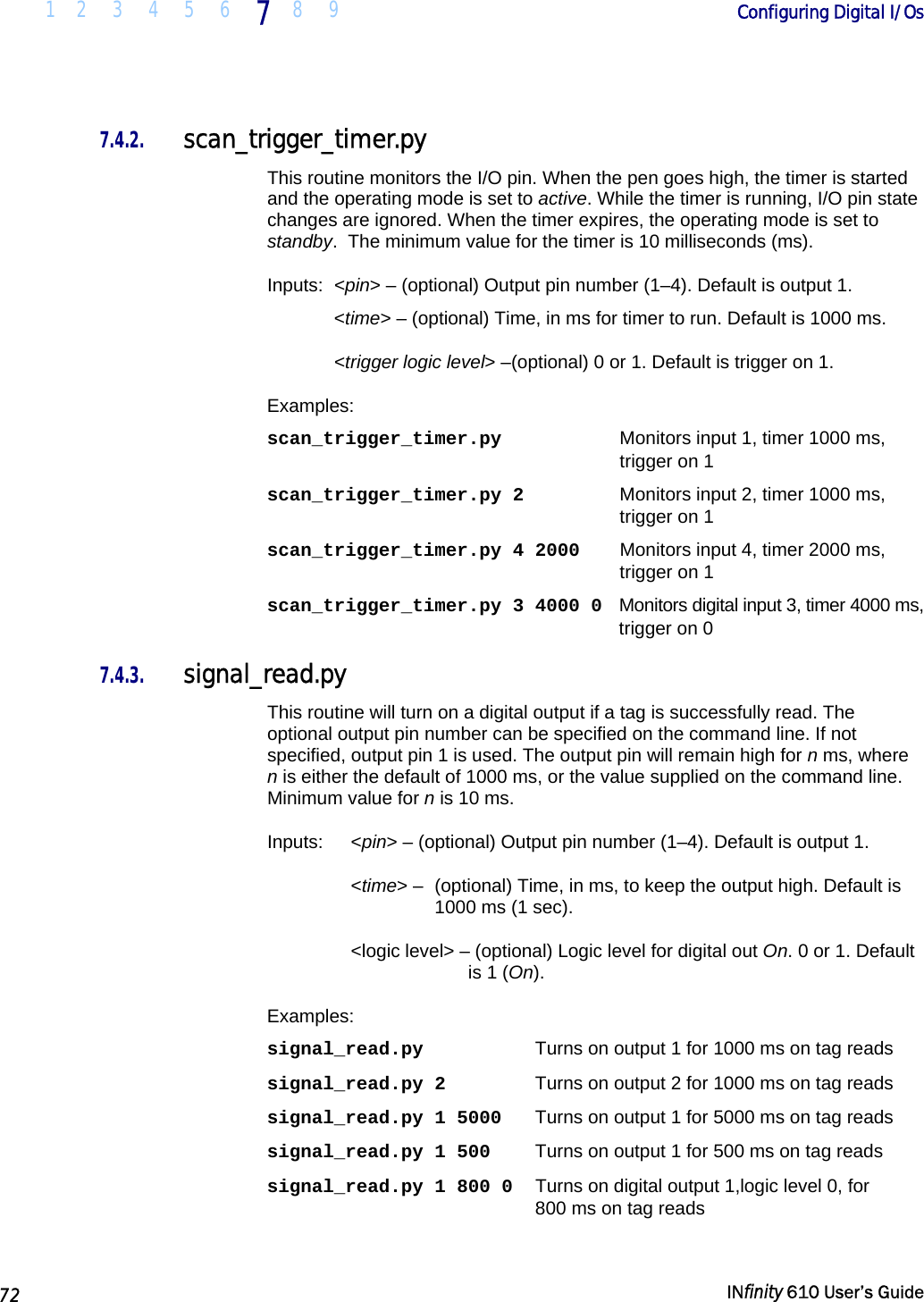
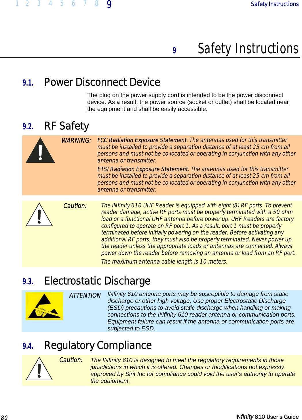
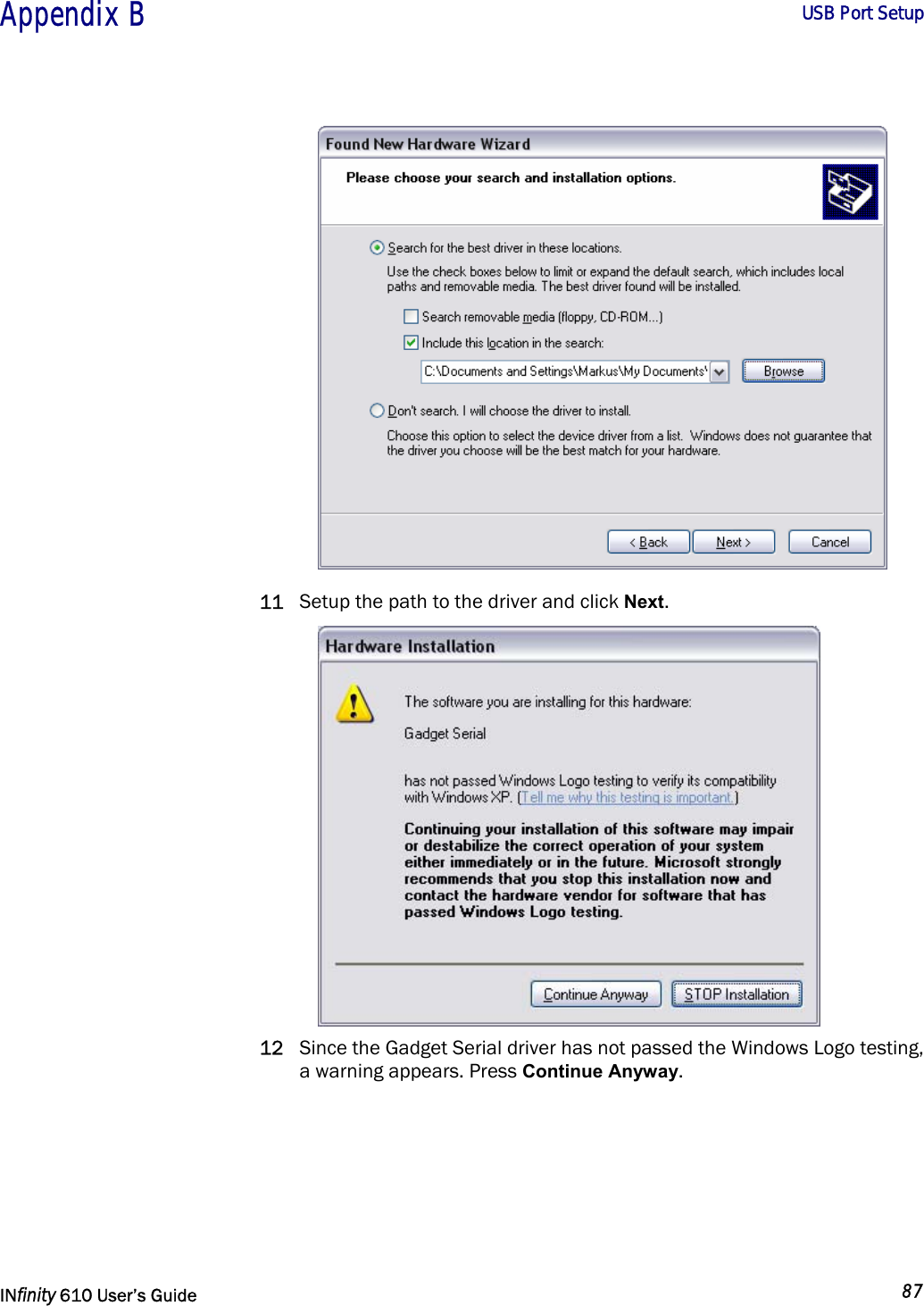
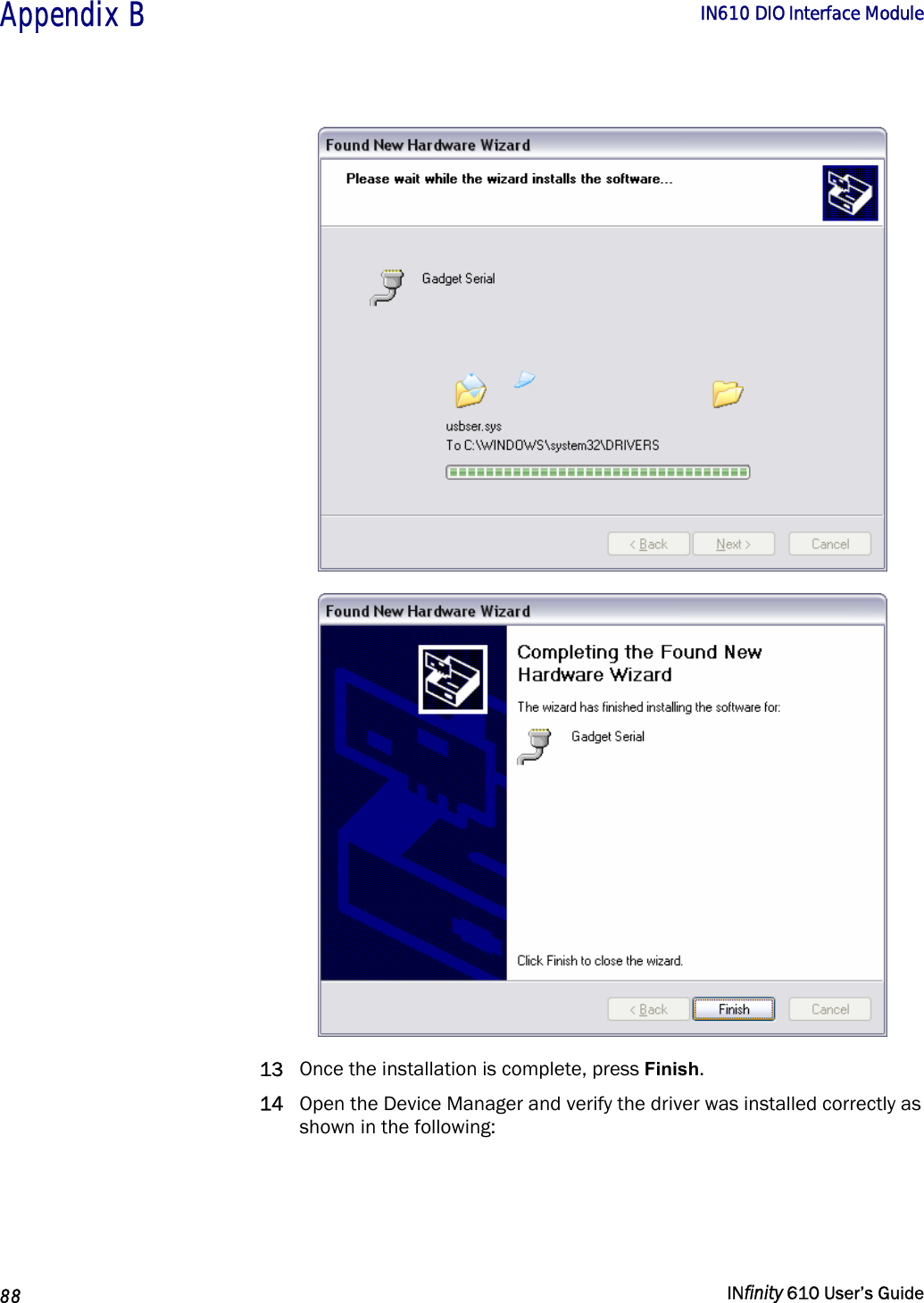
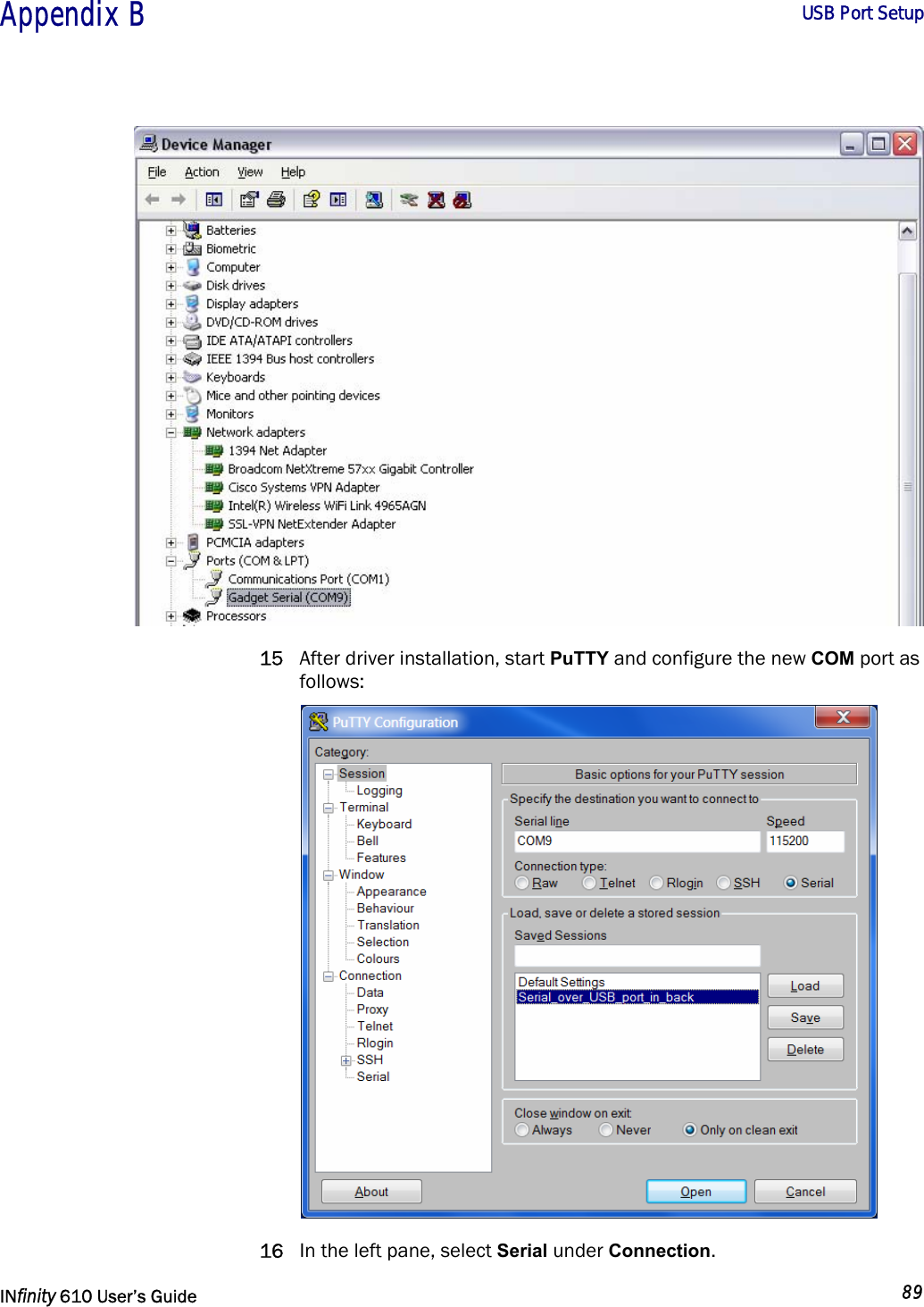
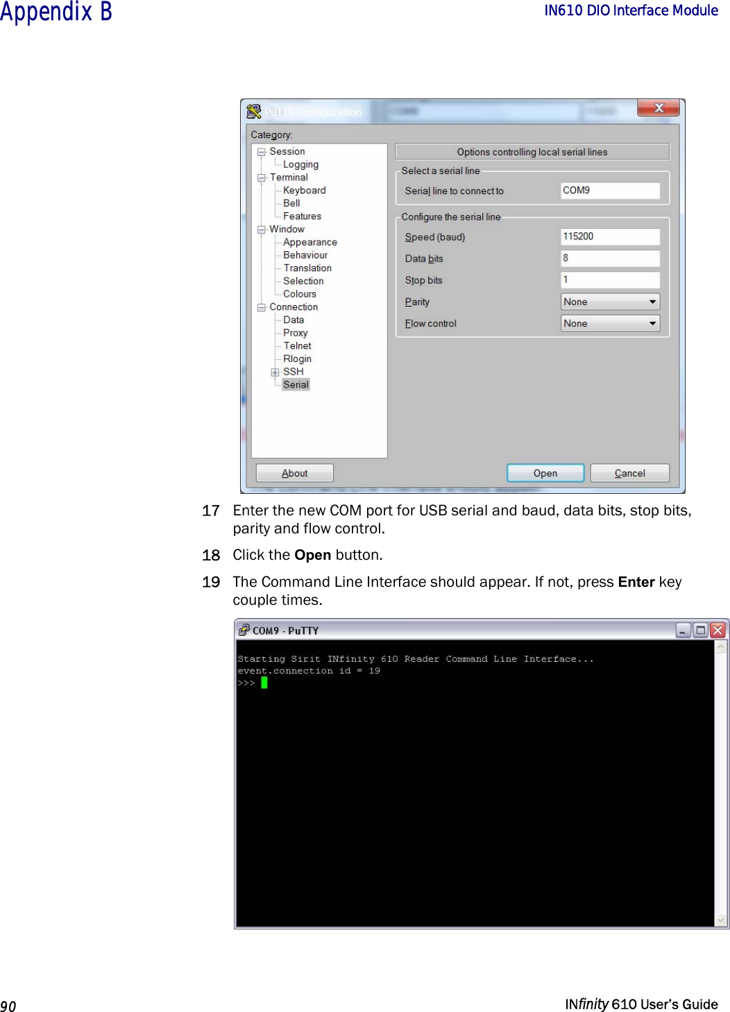
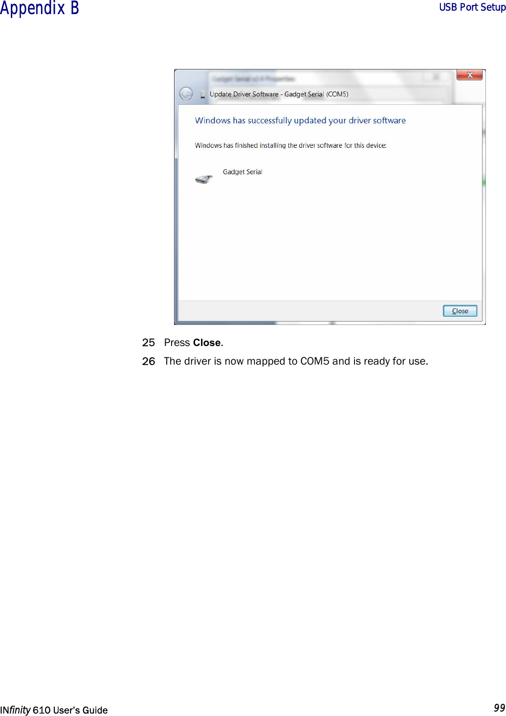
![1 2 3 4 5 6 7 8 9 Reader Startup Tool 32 INfinity 610 User’s Guide 5.5.4. Macros Page The Macros page allows the reader to manage macro files. The macros are provided by Sirit or can be written by the end user. Some of the macros provided are dependent on the operating region of the reader. A macro (script or command file) is a text file that contains one or more reader commands. These commands are used to configure the reader to a known configuration. The Macros can contain variables. These variables are resolved by a dialog box (Macro Variables) that appears when the Send to Reader button is selected. The syntax of a variable is: [$variable_name] During execution, the variable is replaced with user entries into the Macro Variables dialog box. Macros can be edited with any text editor including Windows Notepad.](https://usermanual.wiki/RF-Controls/IN610.Users-Guide-610/User-Guide-1881691-Page-40.png)
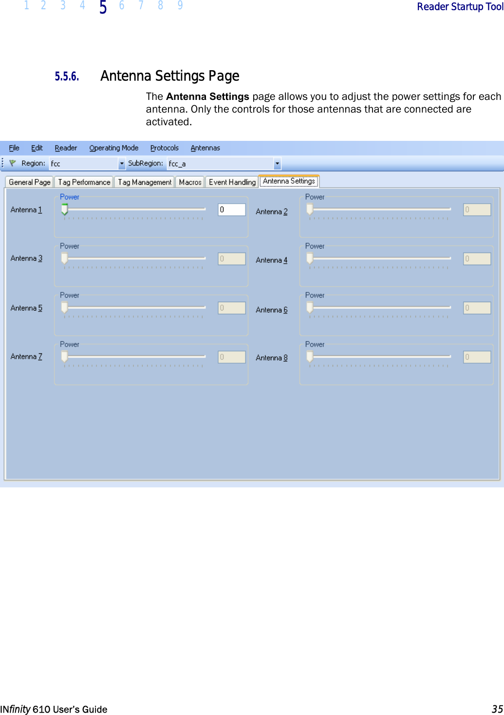
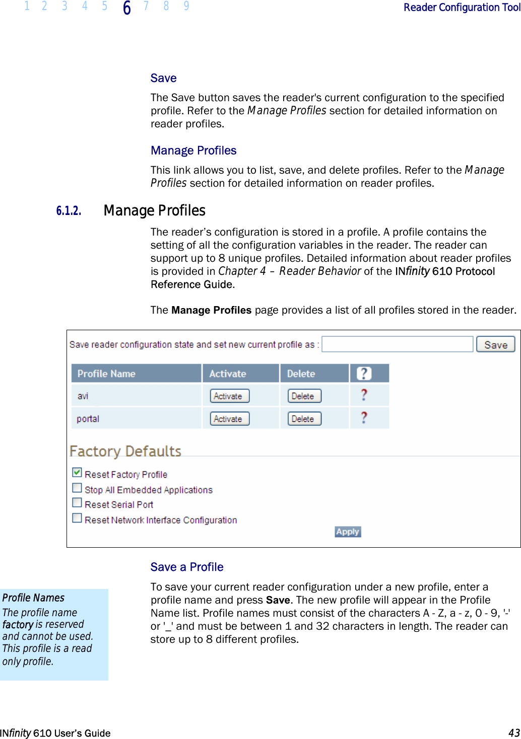
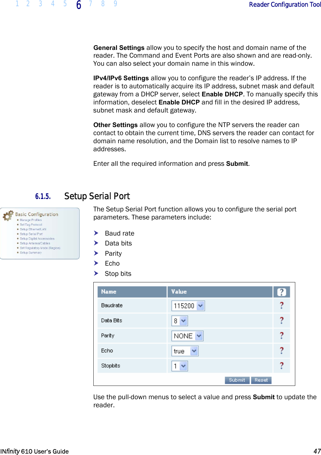
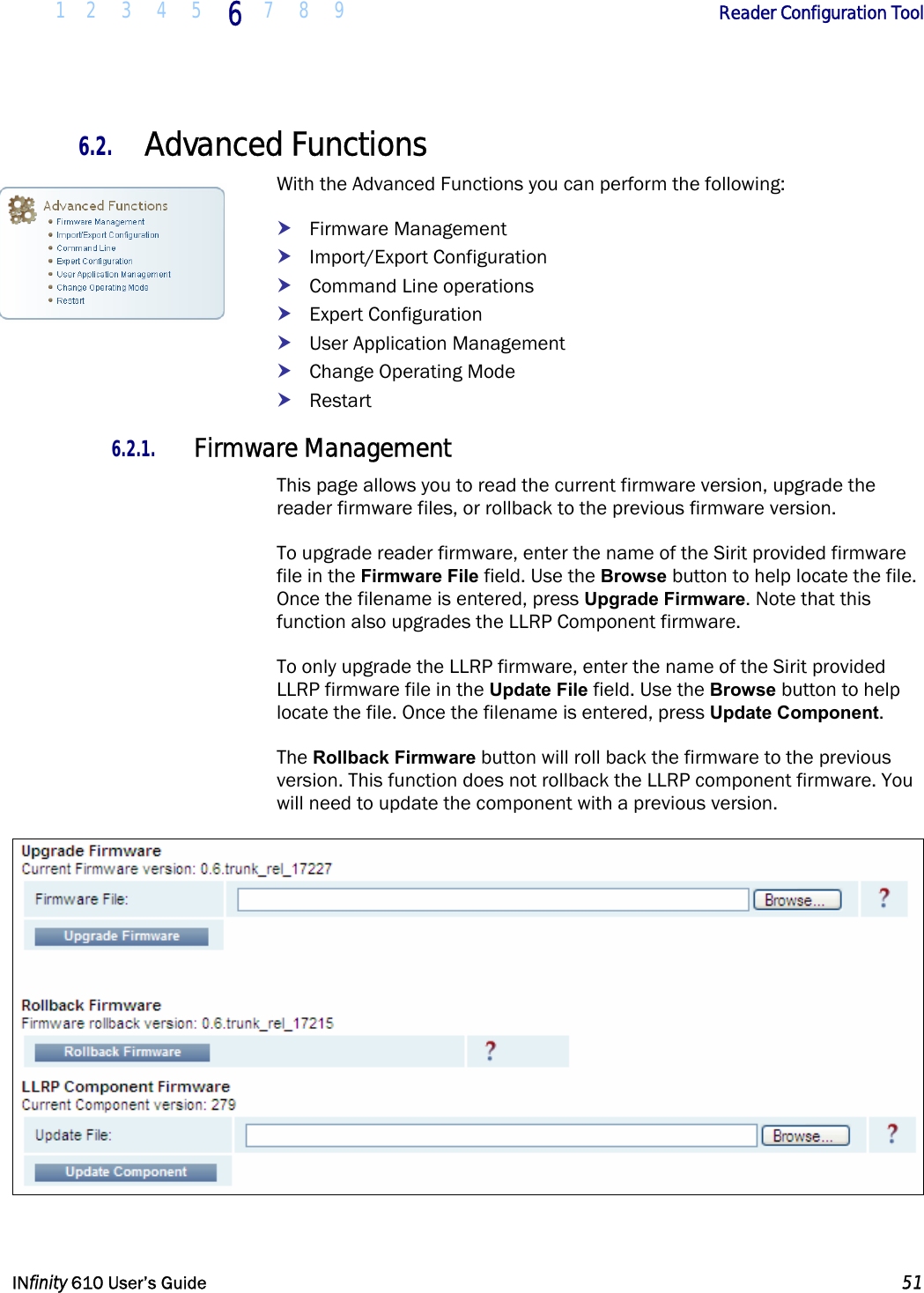
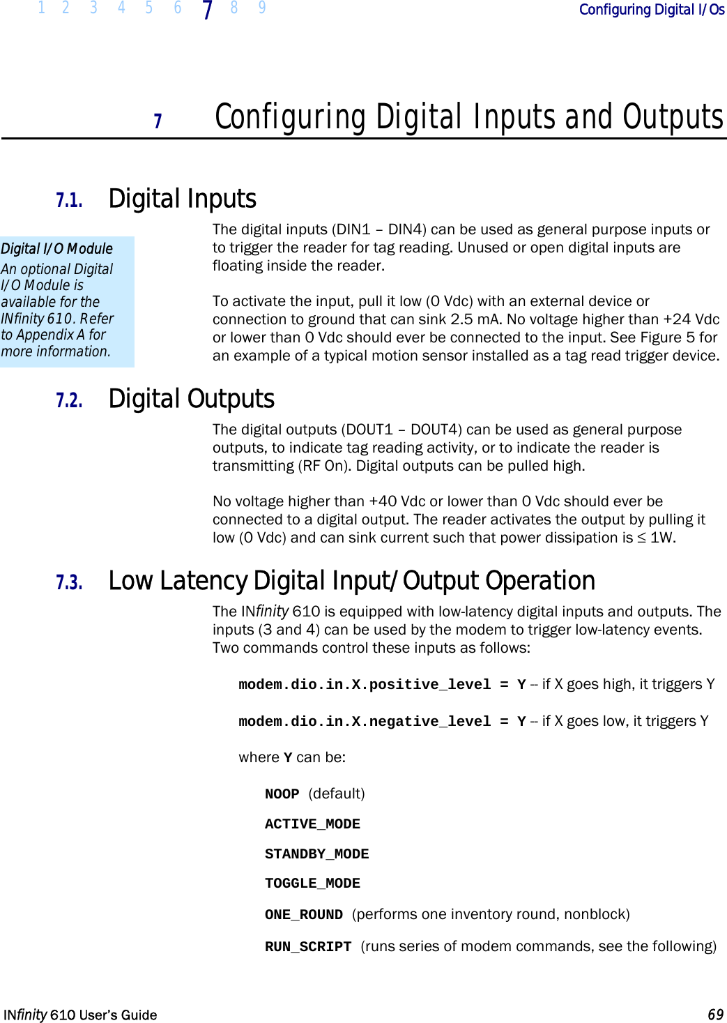
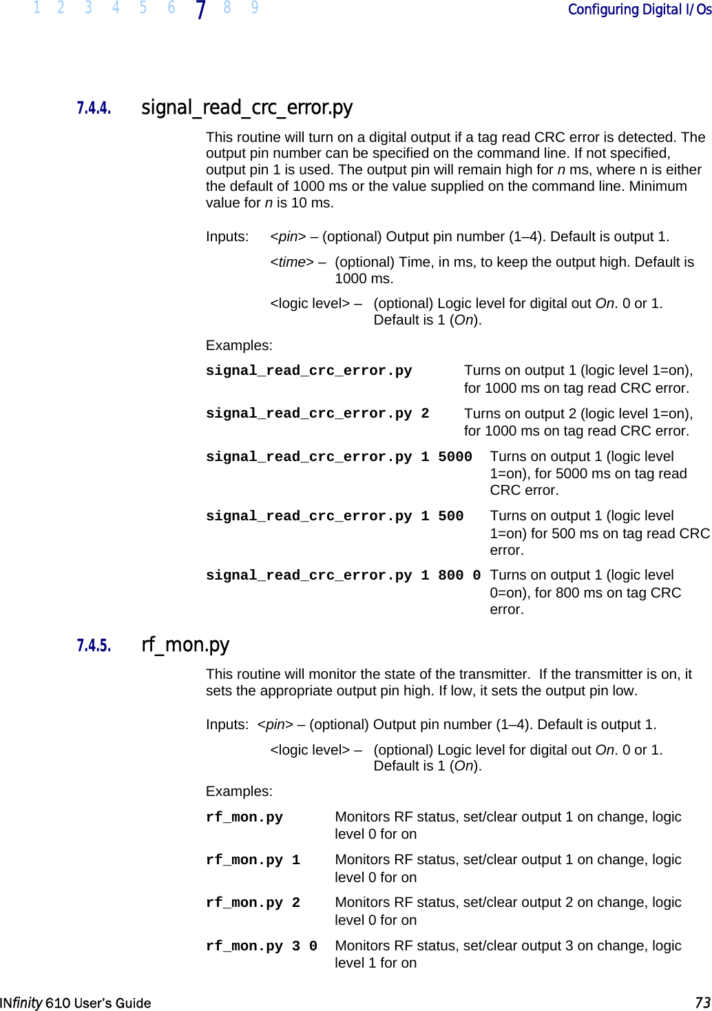
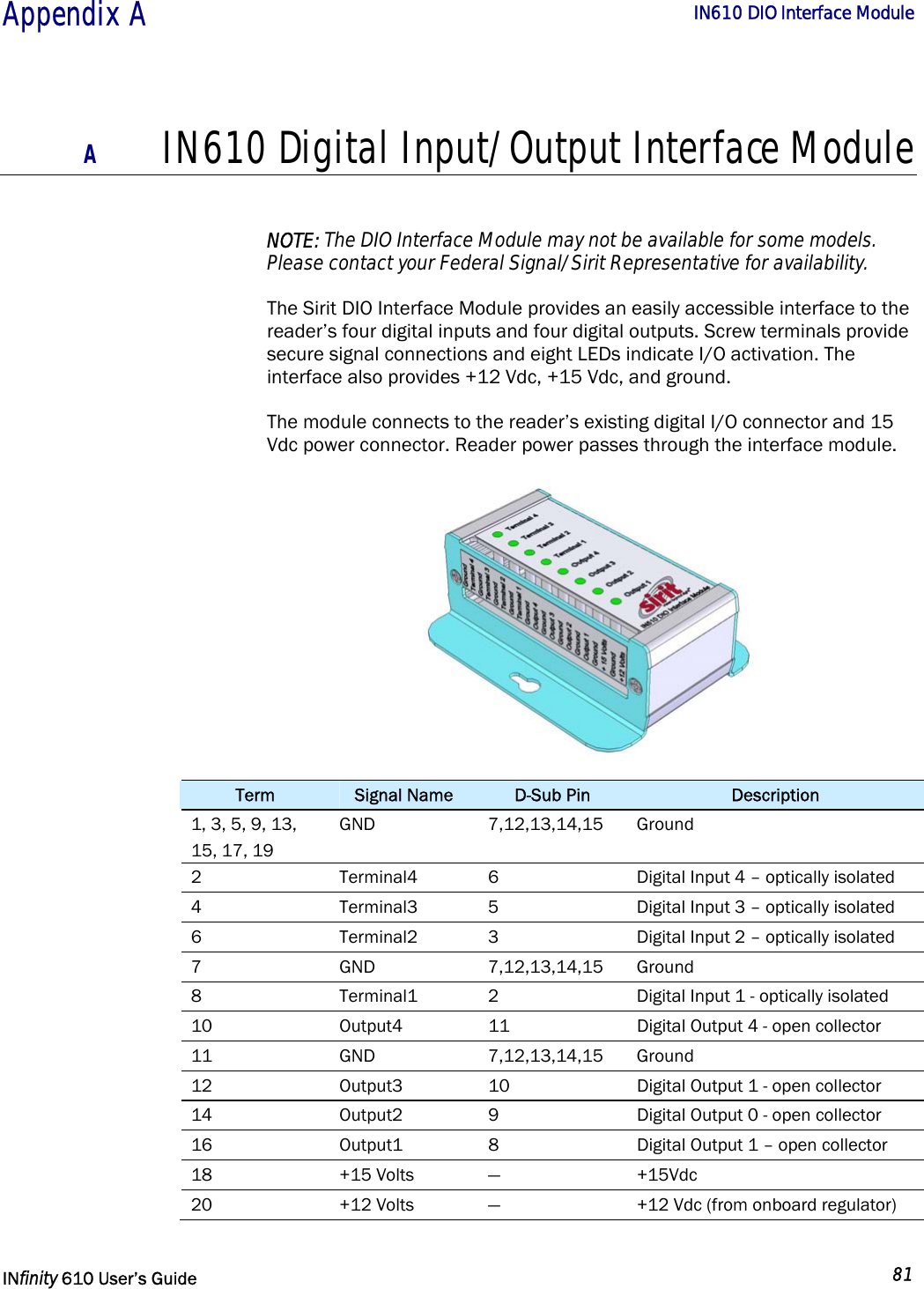
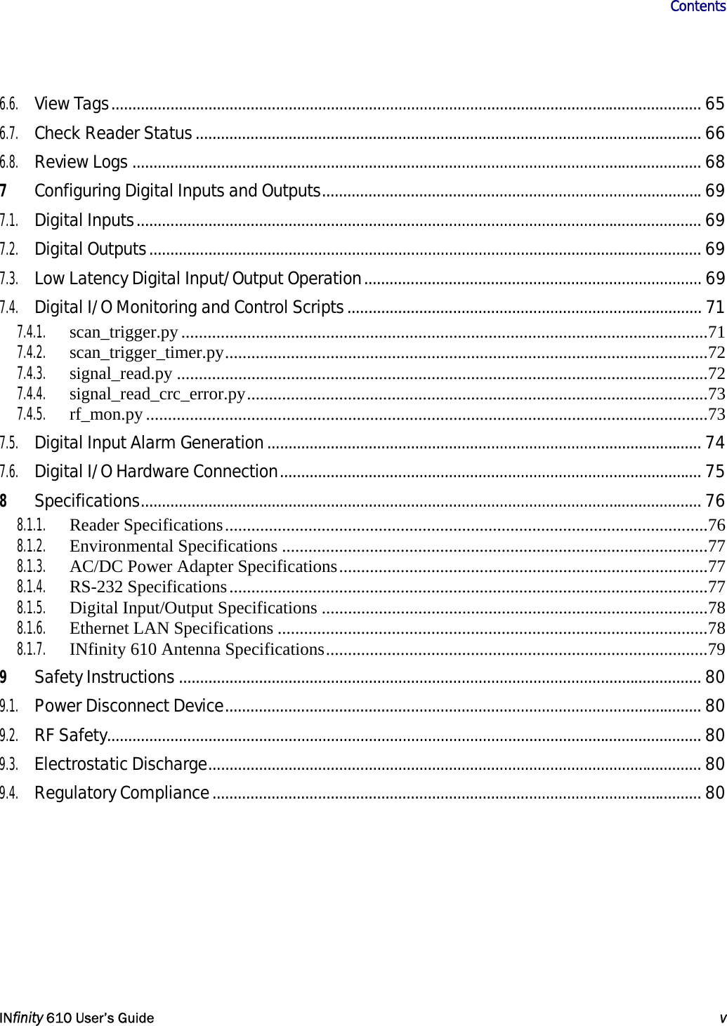
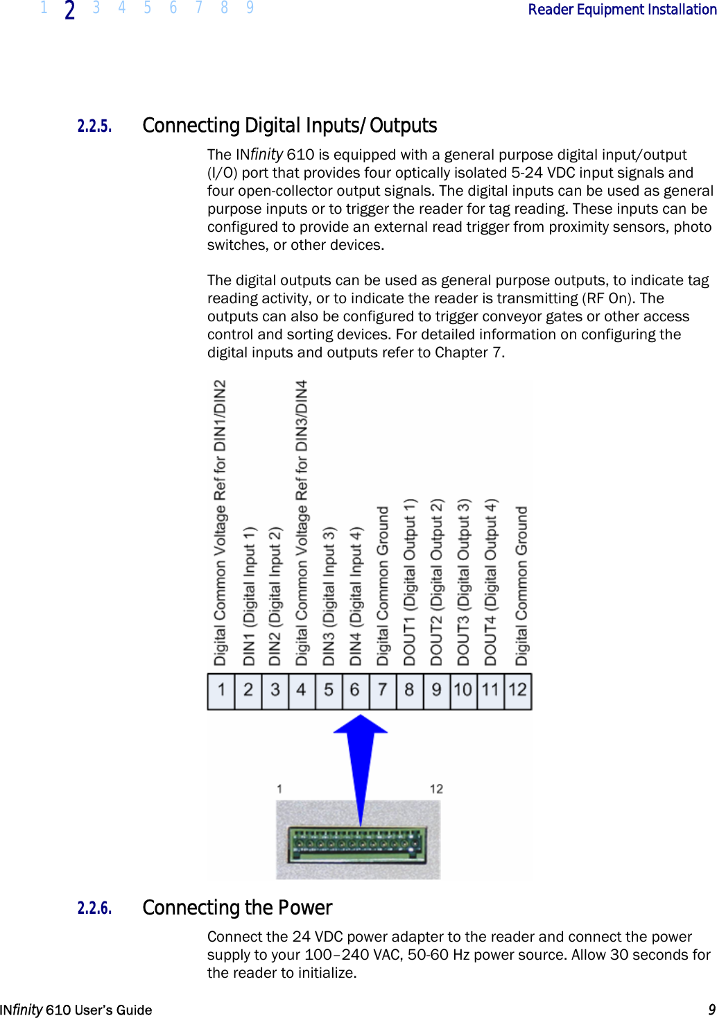
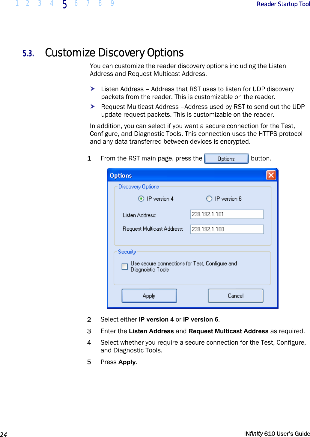
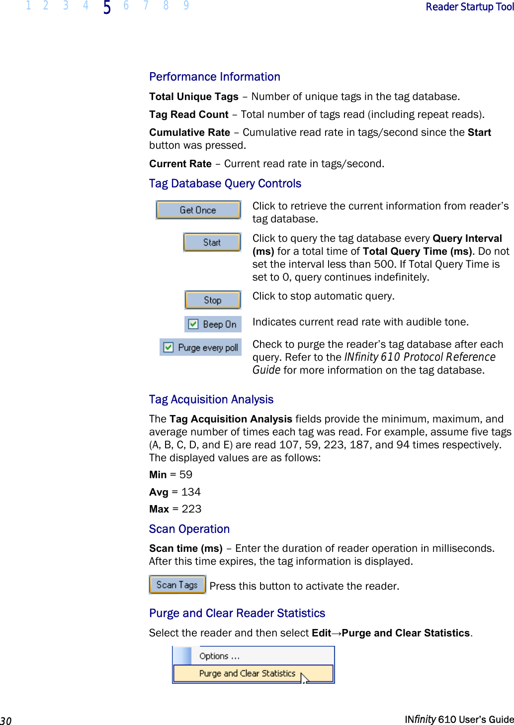
![1 2 3 4 5 6 7 8 9 Reader Startup Tool INfinity 610 User’s Guide 33 Macro Input sub-window The Macro Input window shows the current script that will be sent to the reader when the Send to Reader button is selected. The text in the Macro Input window can be edited prior to being sent to the reader. Macro Output sub-window The Macro Output window is updated after the Send to Reader button is selected. Look at this window to verify that each command line in a script executed correctly. Look for the −−>> ok response from the reader for each command line. Macro Variables Dialog box When a macro is sent to the reader, the values for variables must be resolved via this Windows Dialog box. You can [tab] to each value field and enter the desired value. For example, one macro can be used for two different applications by using variables for antenna selection and transmit power. Macro Example To configure the reader for ETSI, EN302208 Dense, four-antenna portal operation, send the following macro (en302208_12tari_lf320_PR_M4.mcr): # configure region setup.region=etsi setup.sub_region=EN302208_DENSE antennas.mux_sequence=[$antenna_mux_sequence] antennas.1.conducted_power=[$power_ddbm] antennas.2.conducted_power=[$power_ddbm] antennas.3.conducted_power=[$power_ddbm] antennas.4.conducted_power=[$power_ddbm] # configure protocol modem.protocol.isoc.physical.set(tari=tari_12_50, return_link_freq=LF320, data_1_length=d1_len_20, rt_modulation=rt_mod_pr, tr_encoding=tr_enc_miller_4,interrogator_mode=dense)](https://usermanual.wiki/RF-Controls/IN610.Users-Guide-610/User-Guide-1881691-Page-41.png)