Radwin RW2025 Outdoor radio unit operating in the 2.5-2.7 GHz (BRS) band User Manual STW
Radwin Ltd. Outdoor radio unit operating in the 2.5-2.7 GHz (BRS) band STW
Radwin >
Contents
- 1. User Manual Part 1
- 2. User Manual Part 2
User Manual Part 2
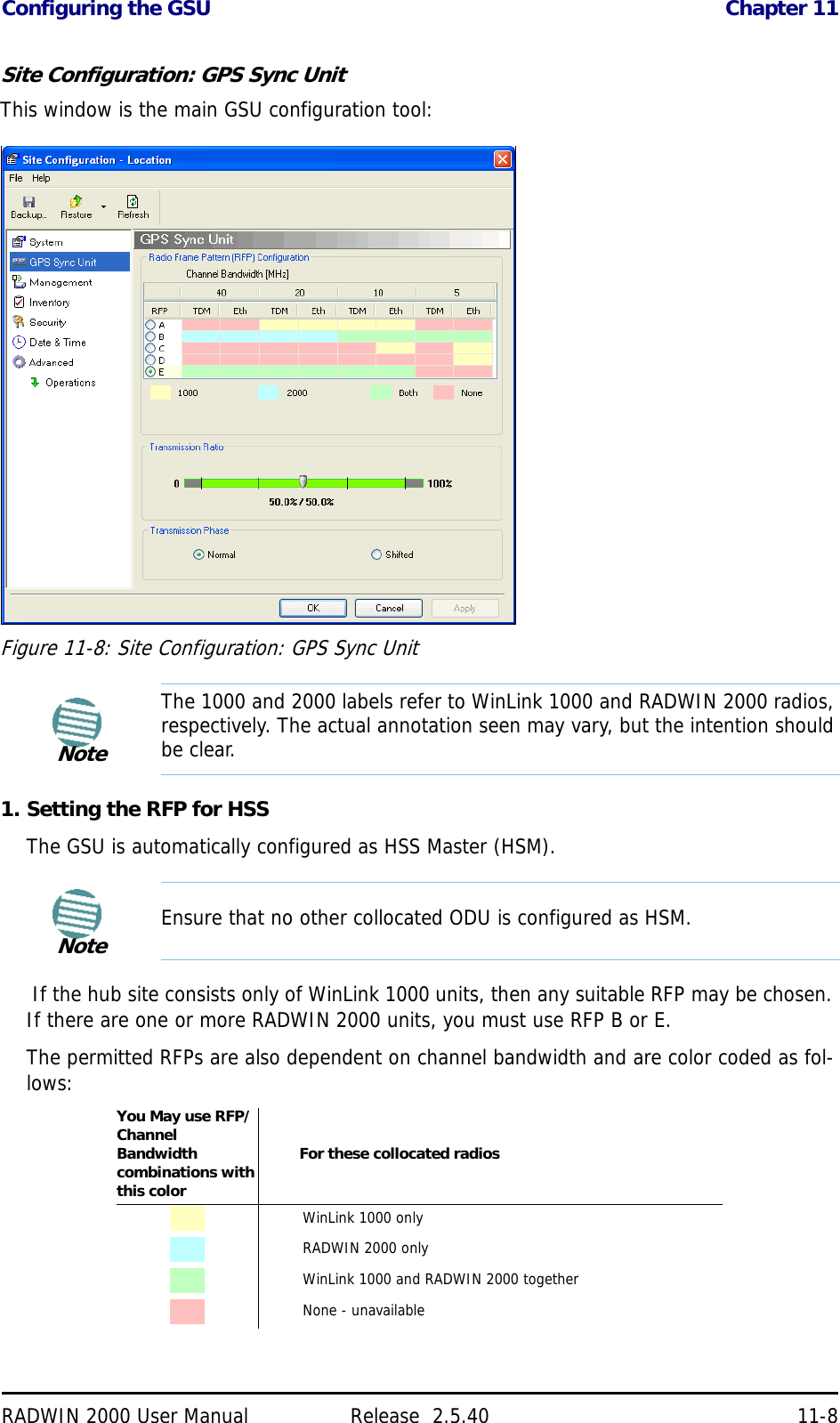
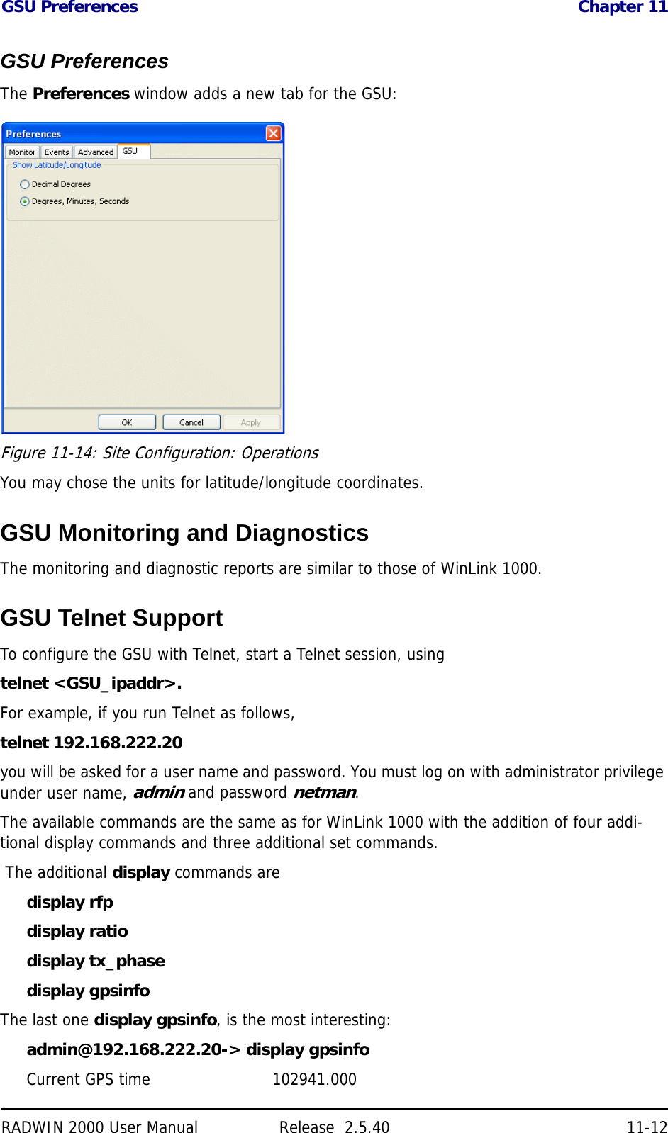

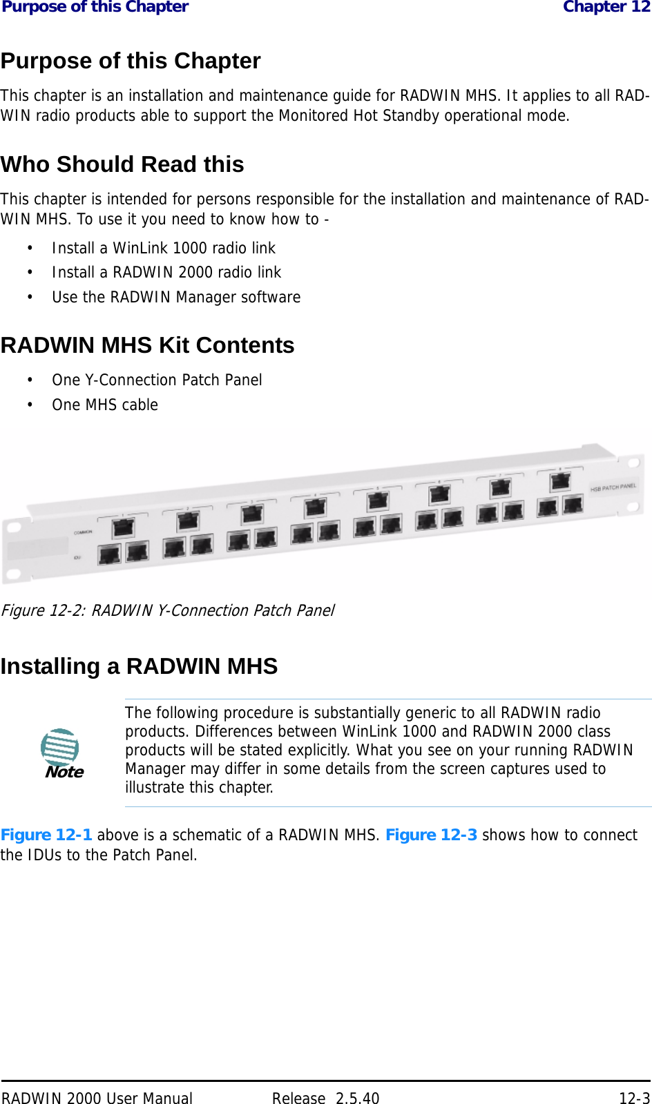
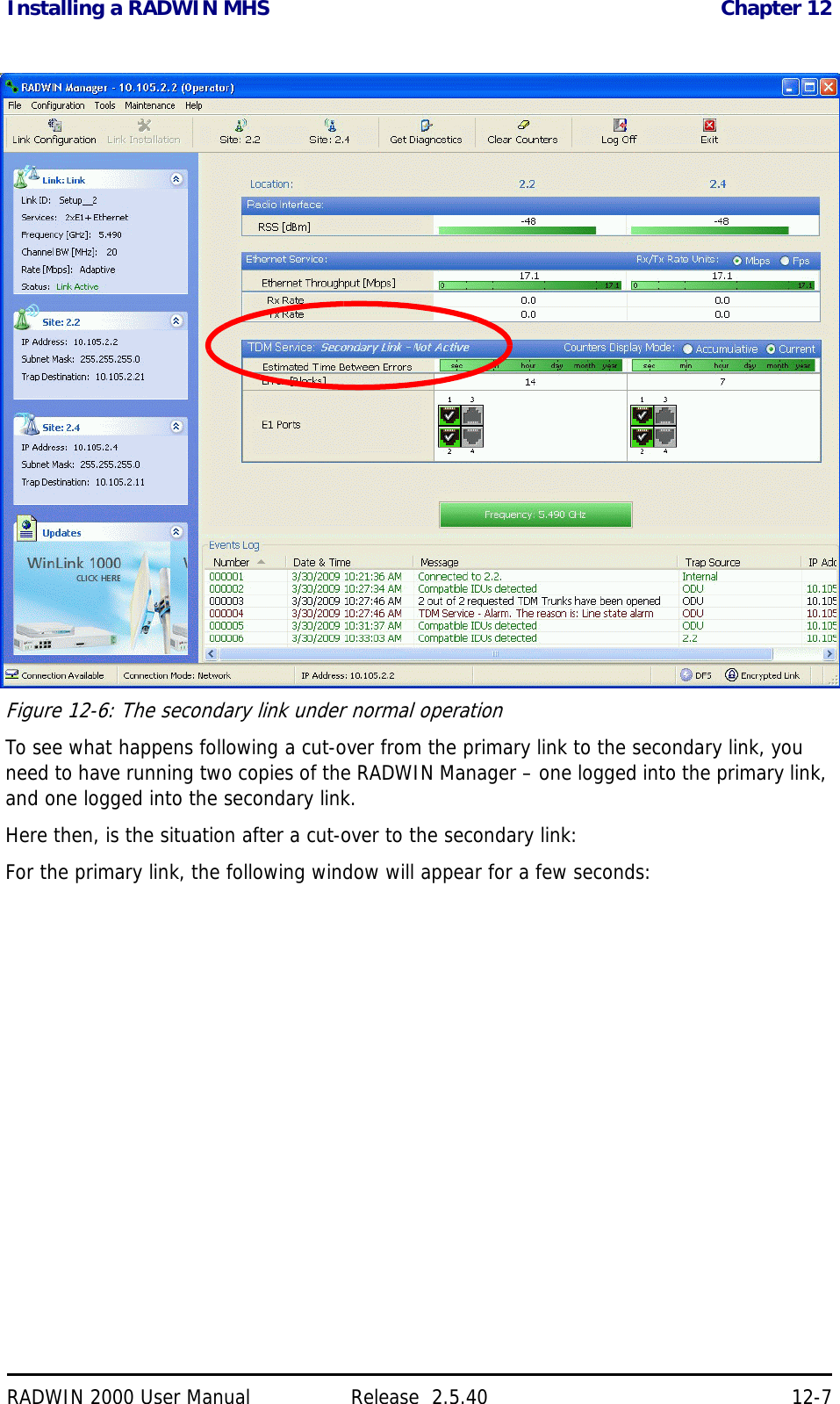
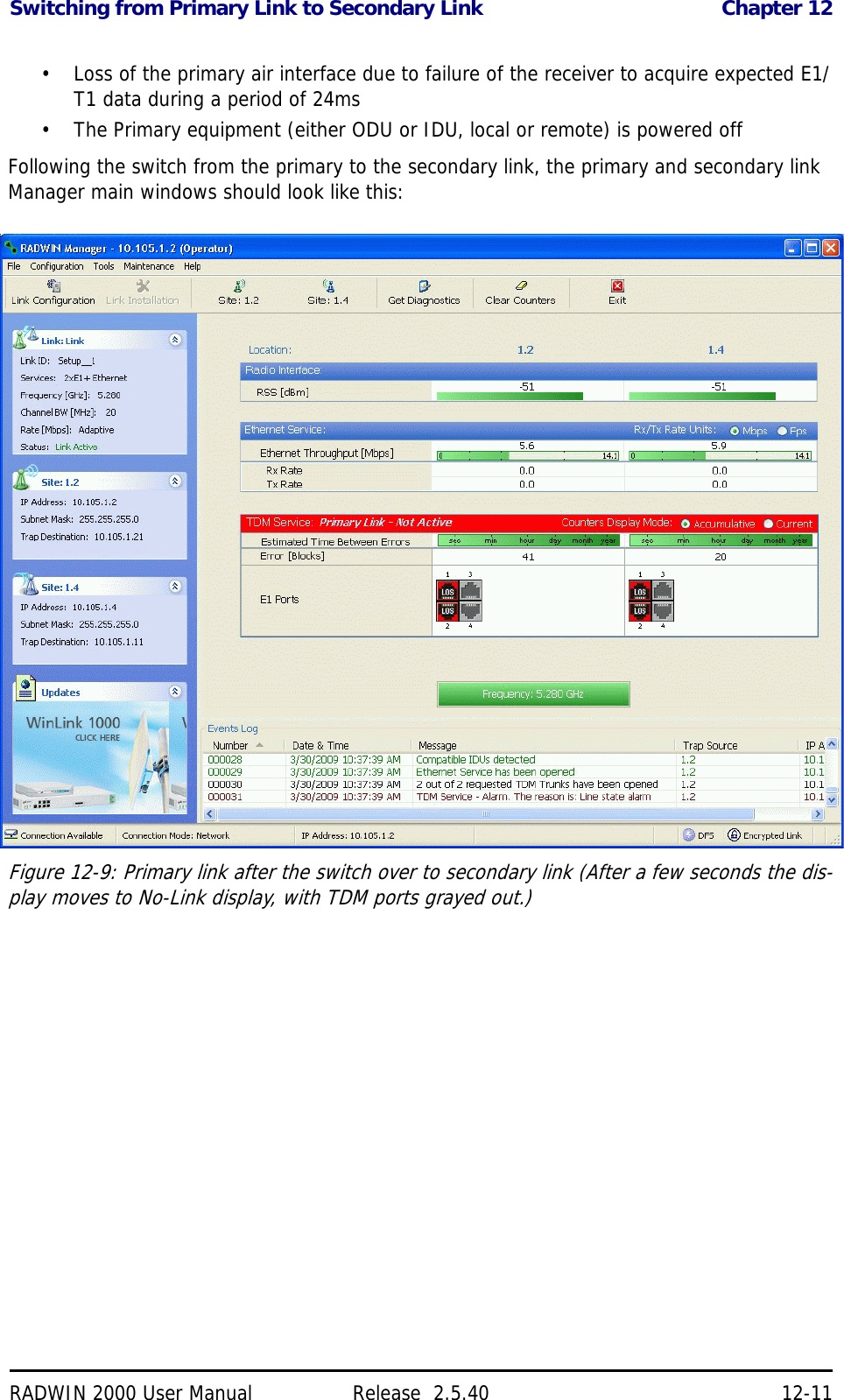
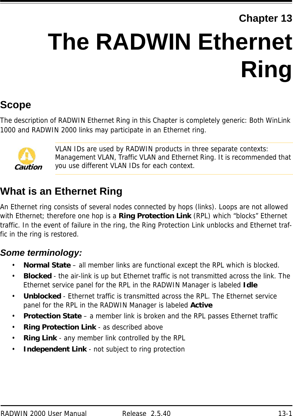
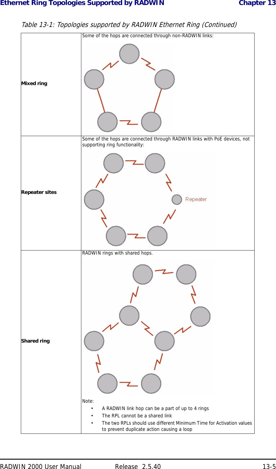
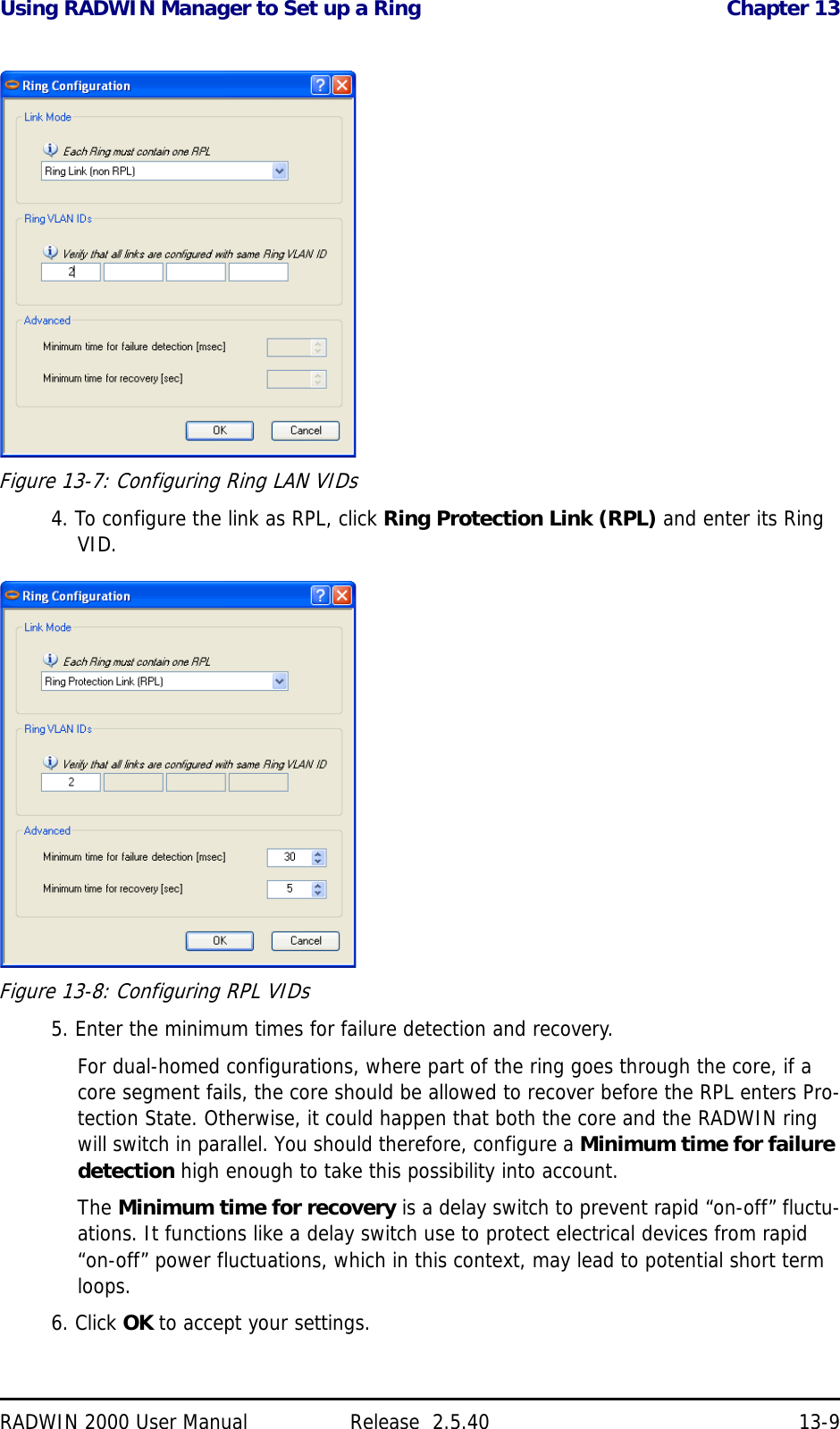
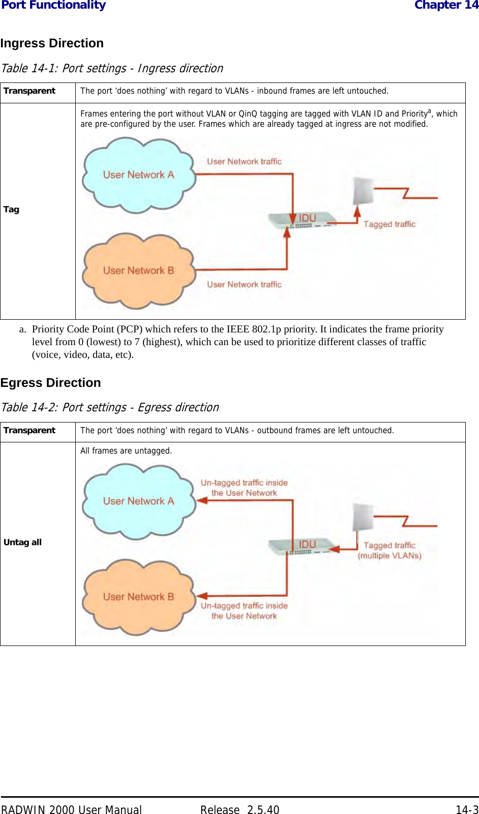
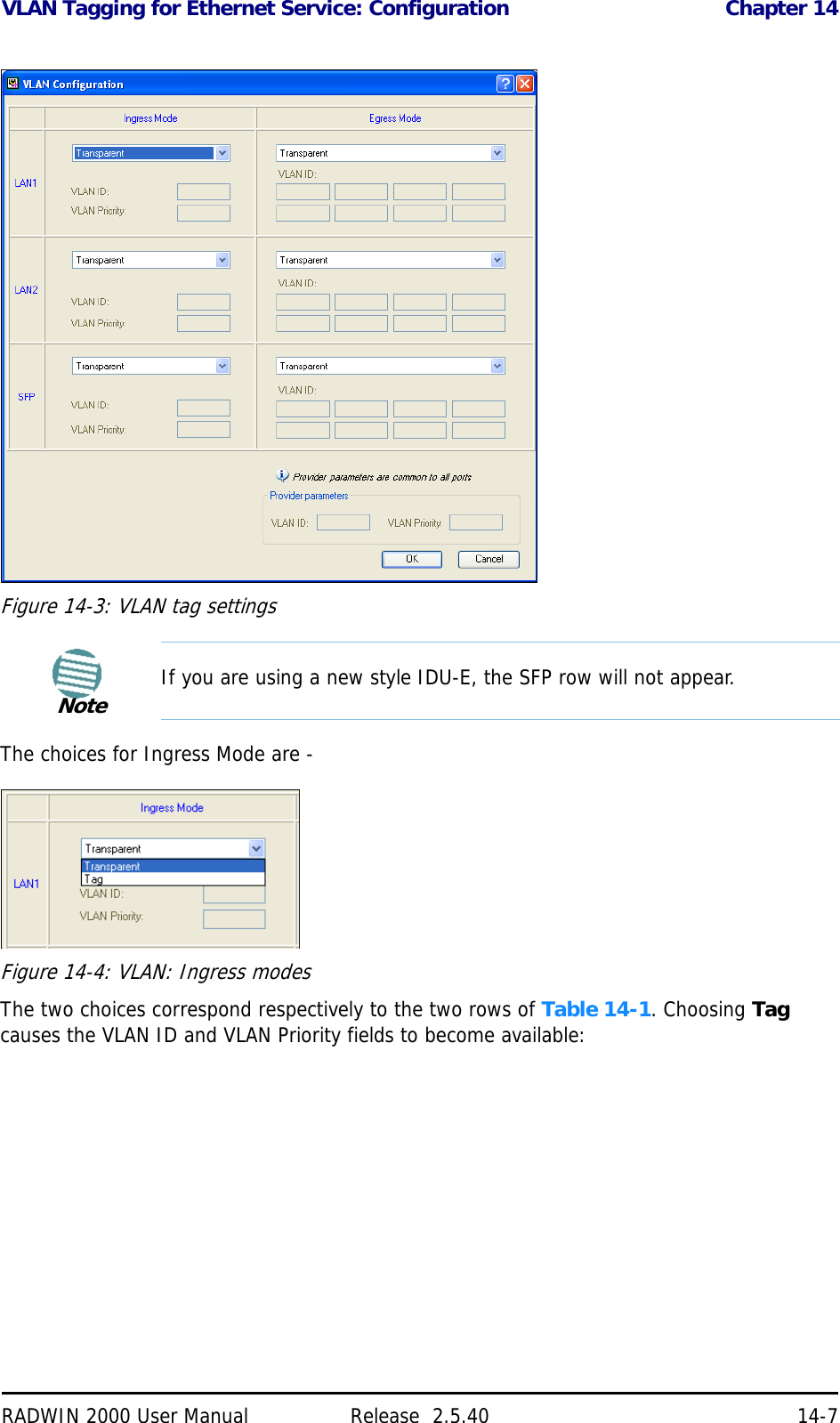
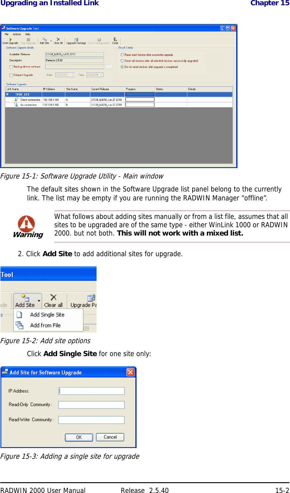
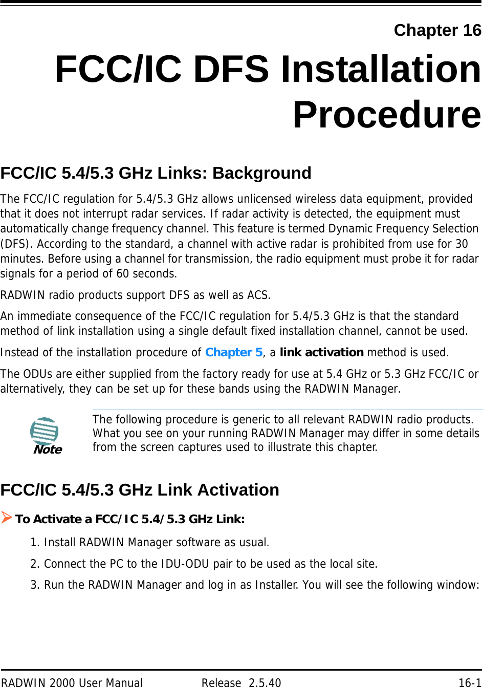
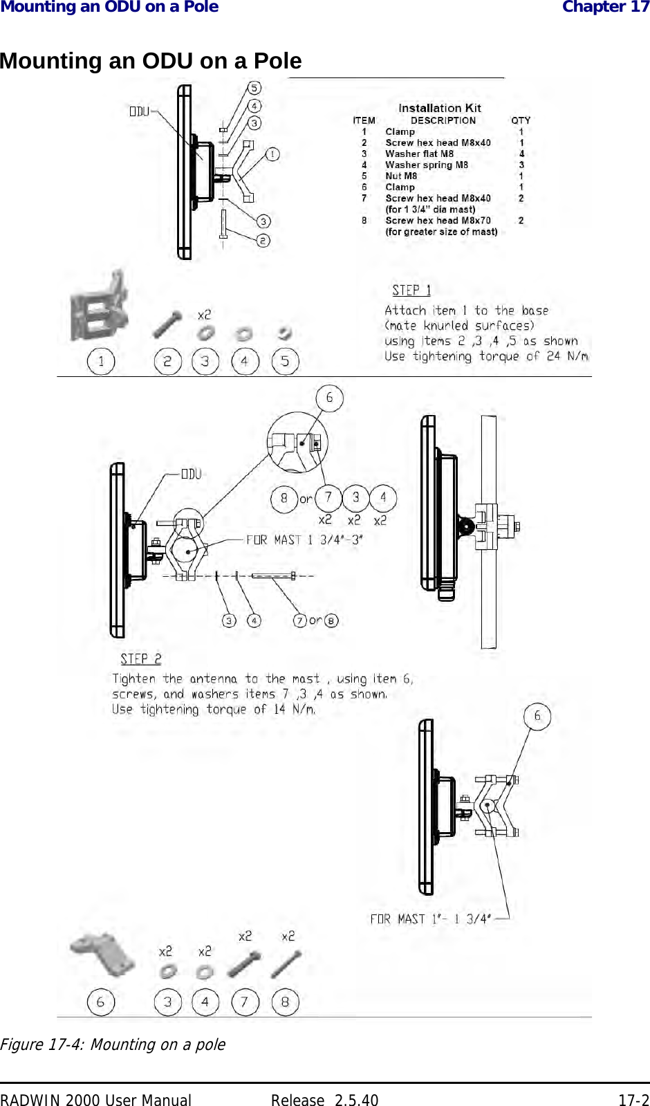
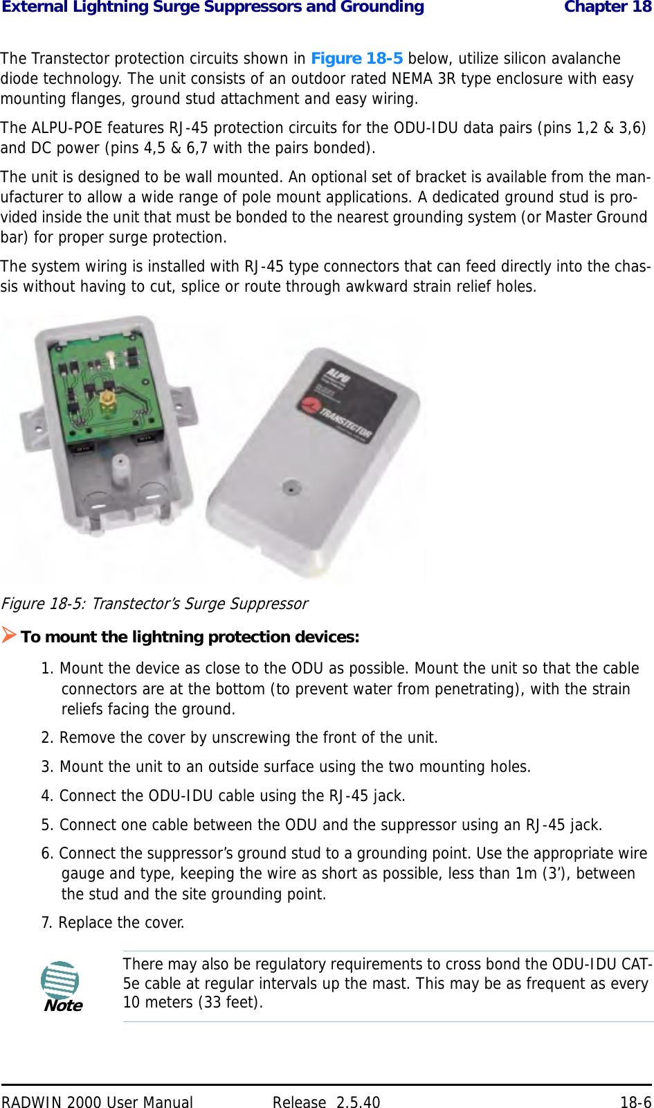
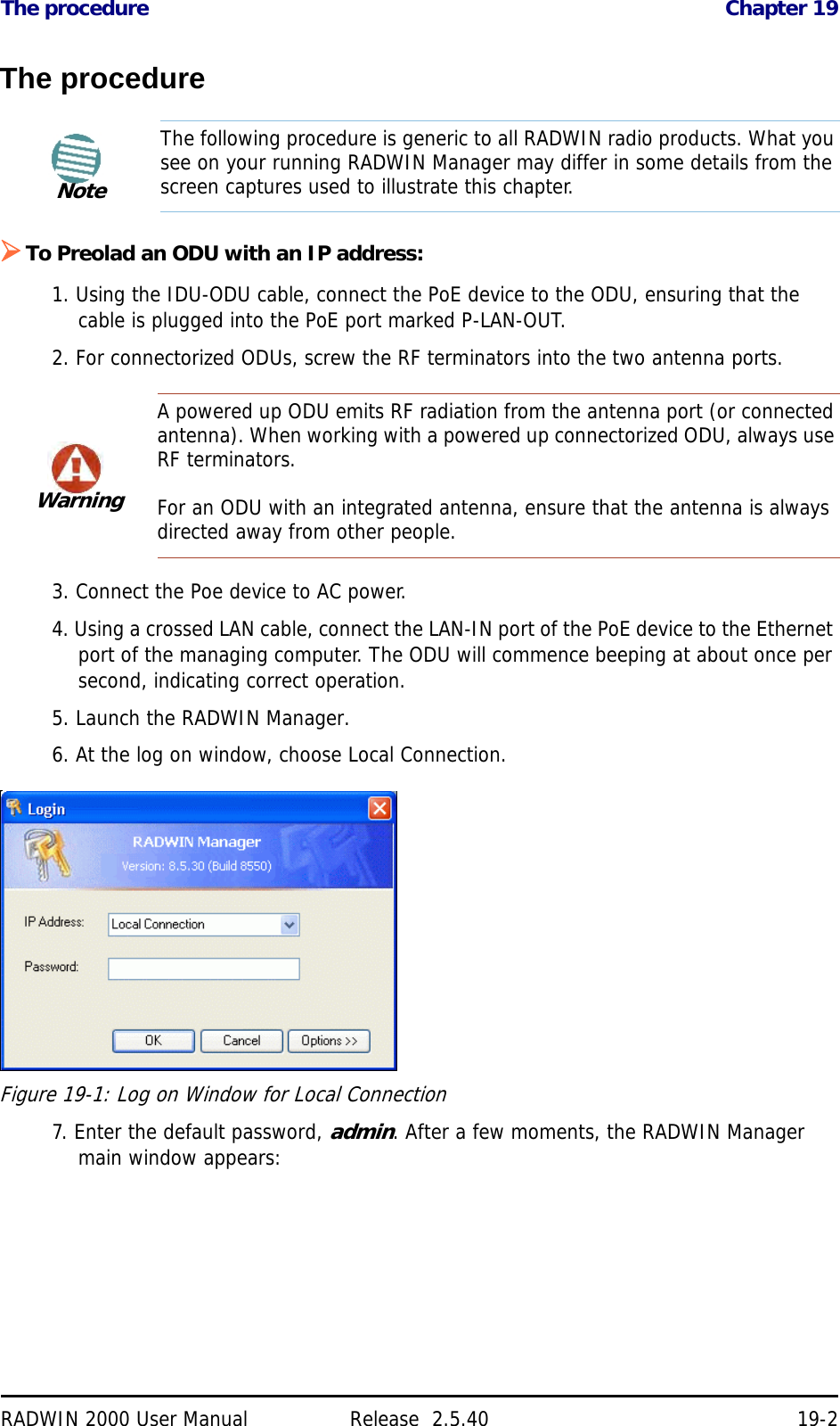
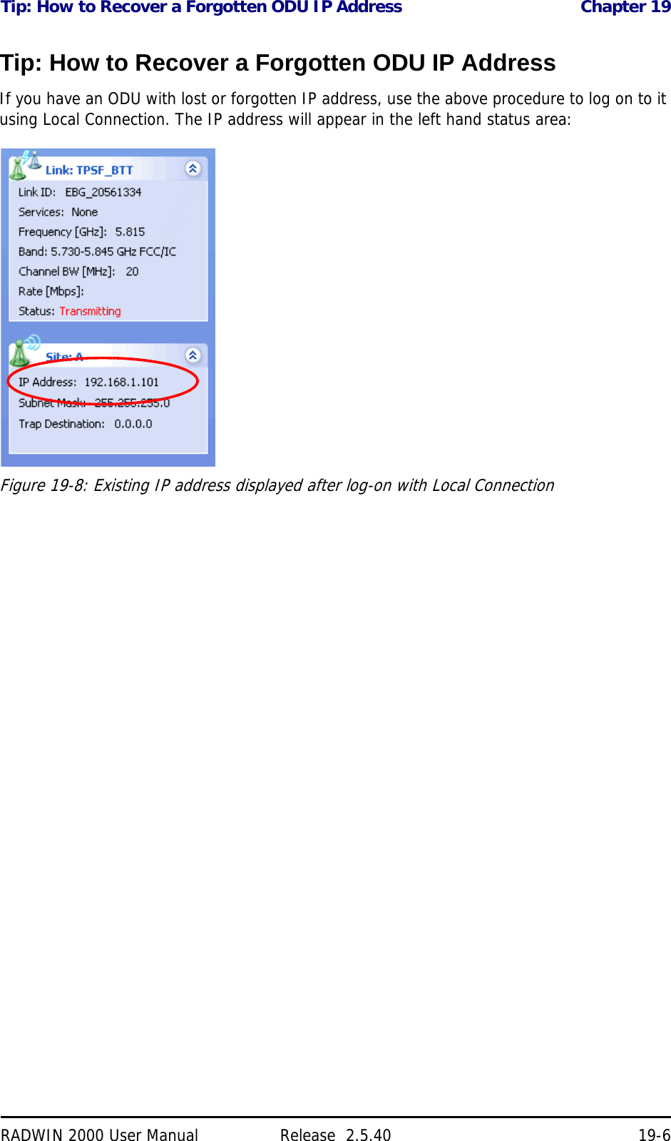
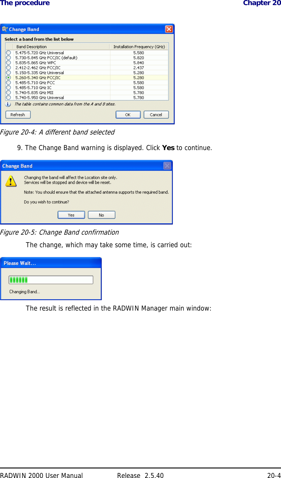
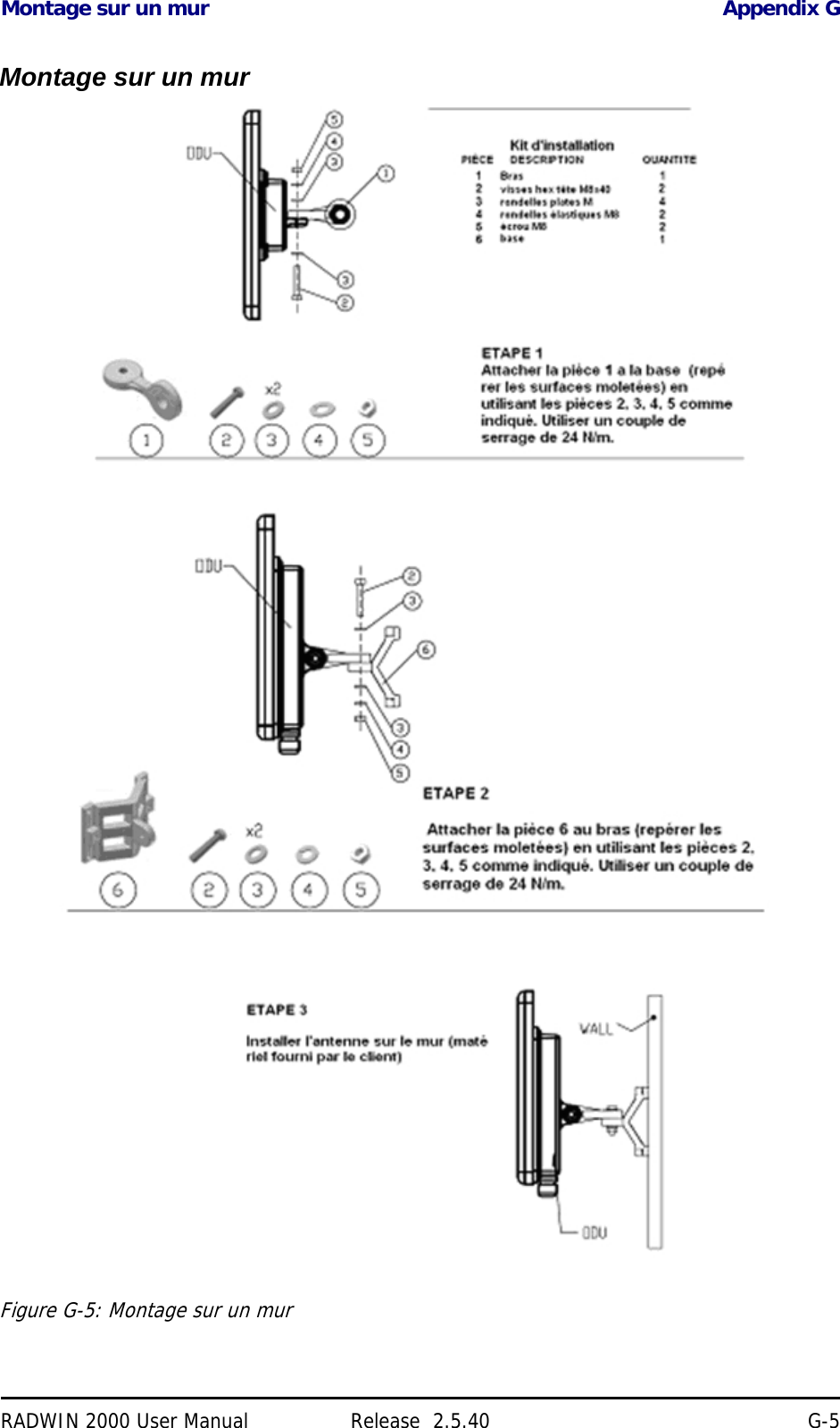
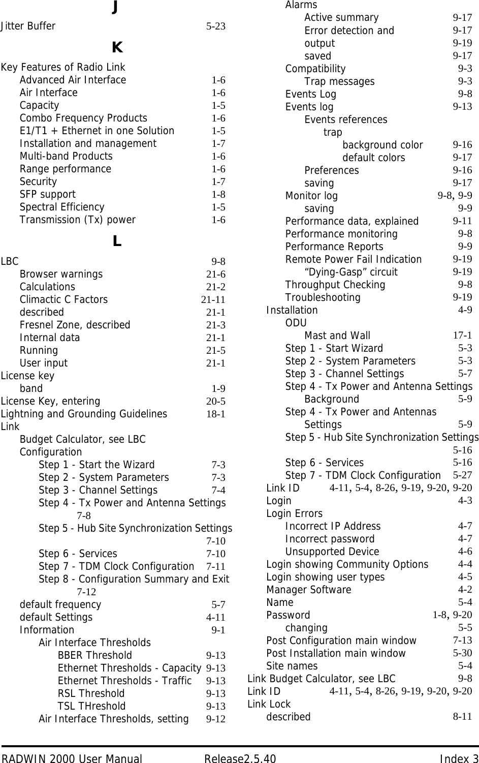
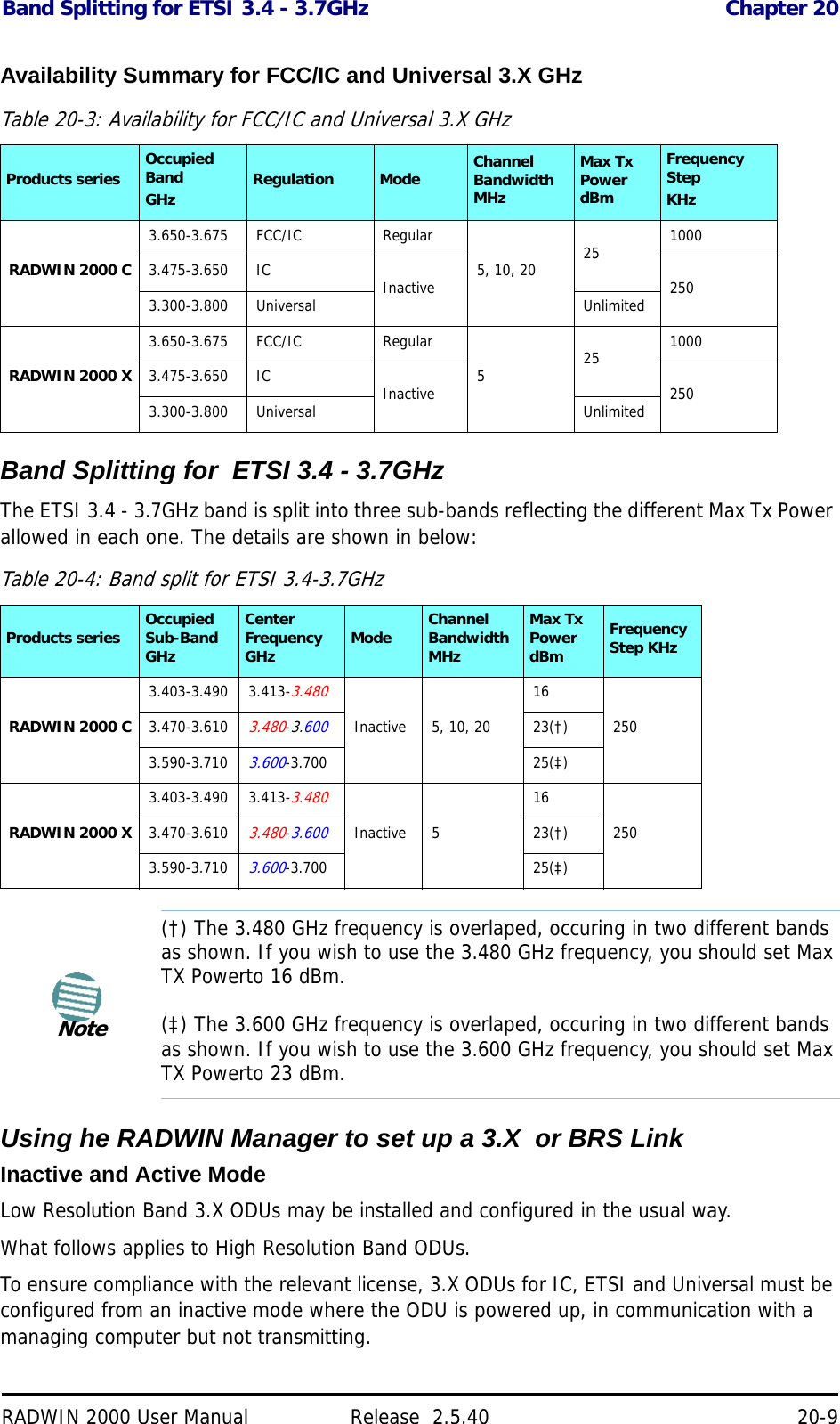
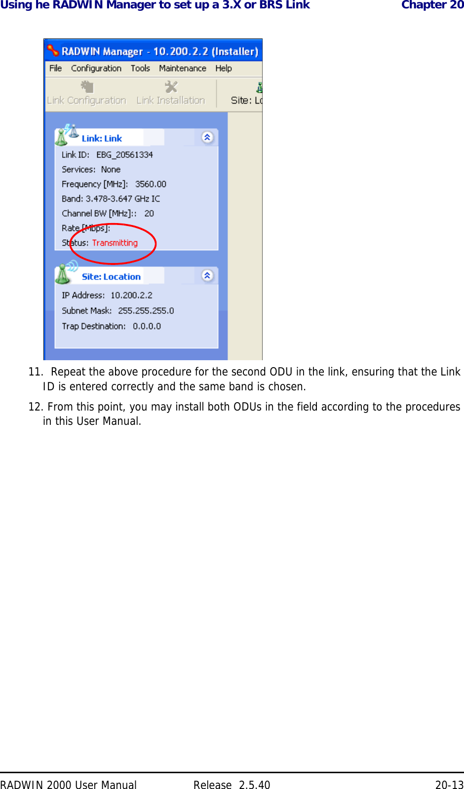
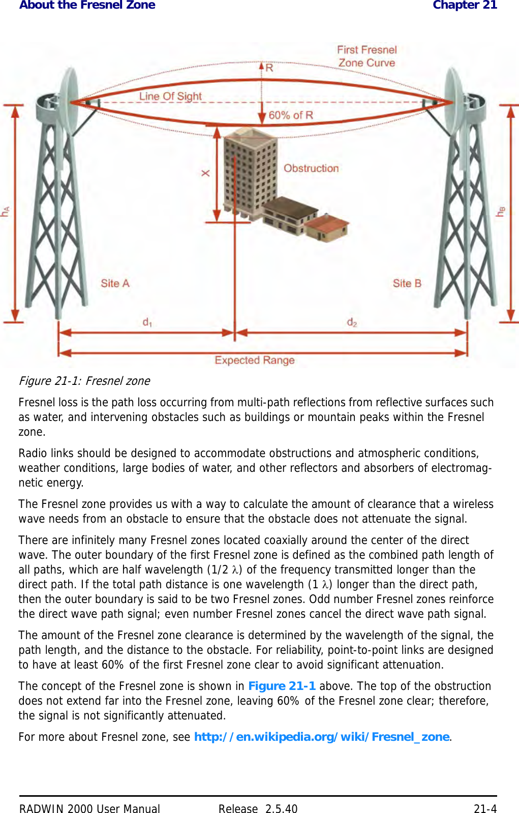
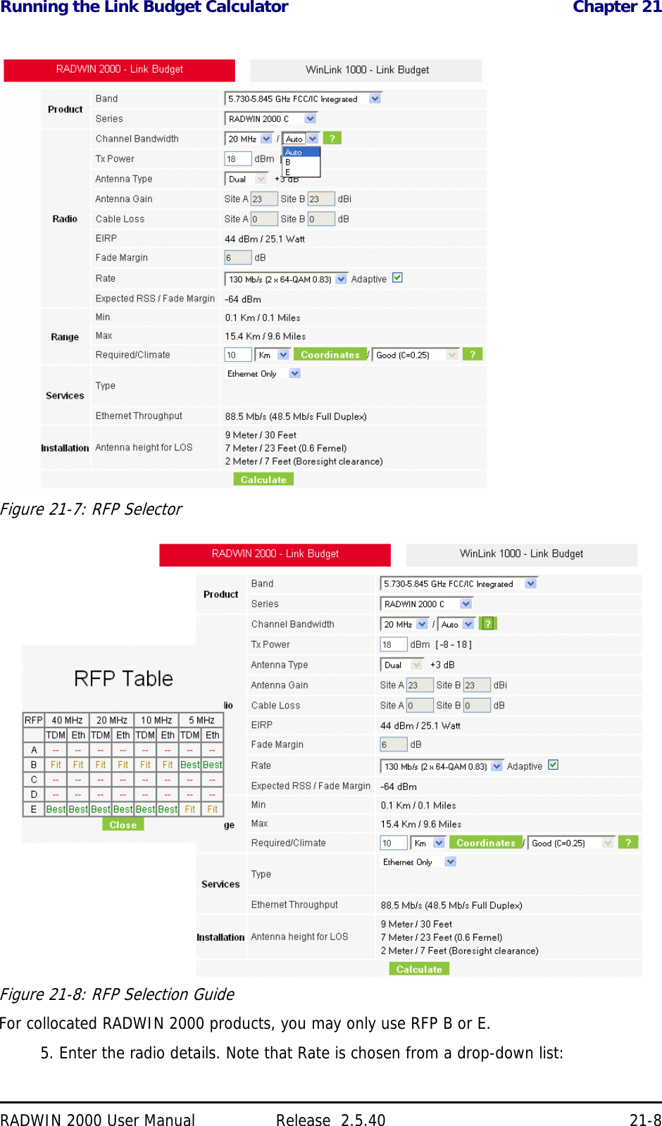
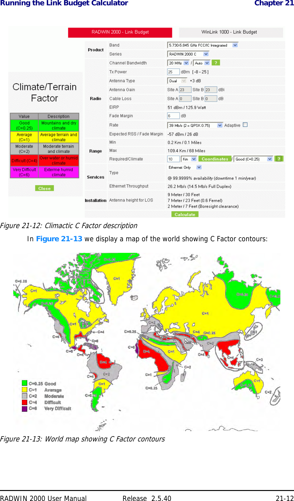
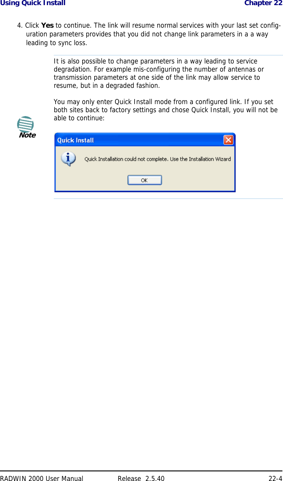
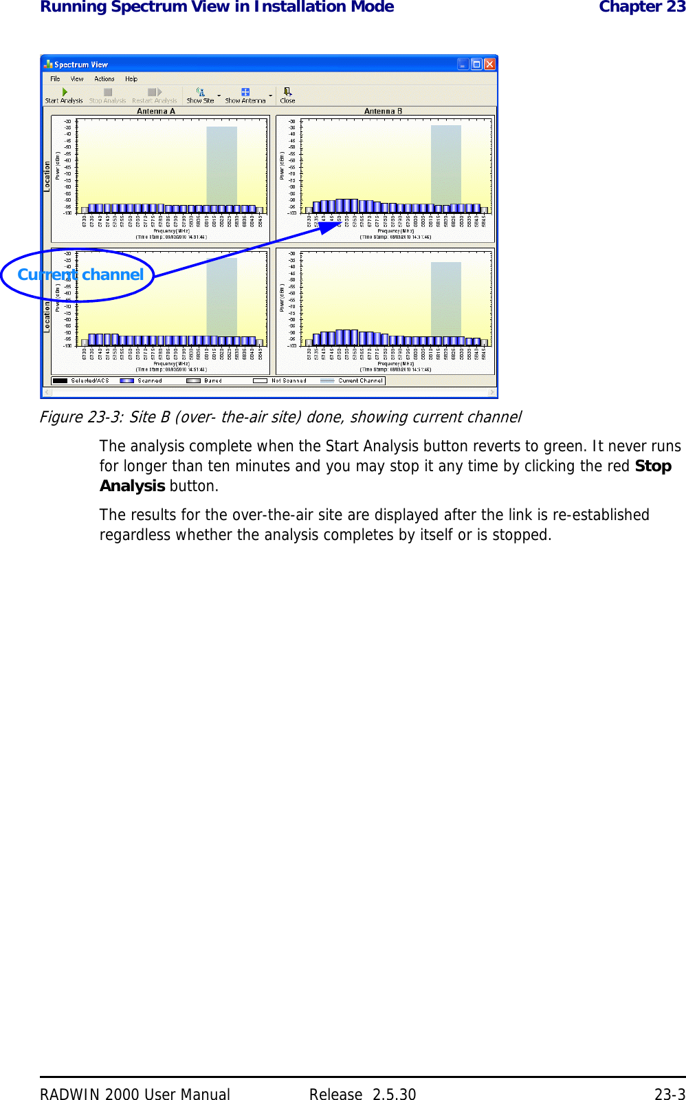
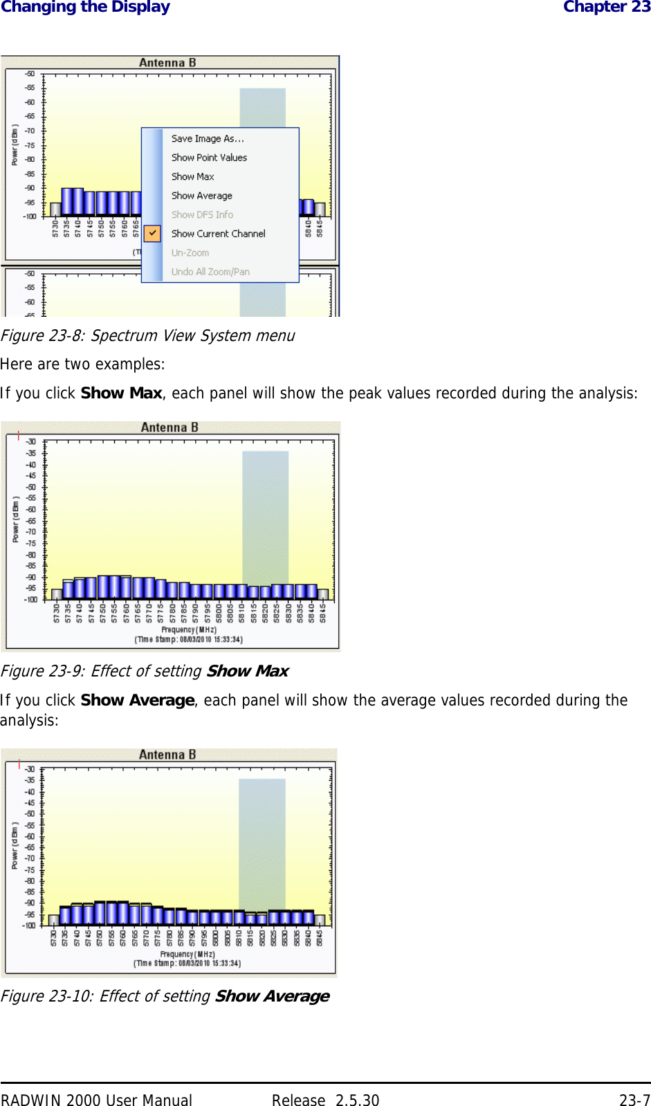
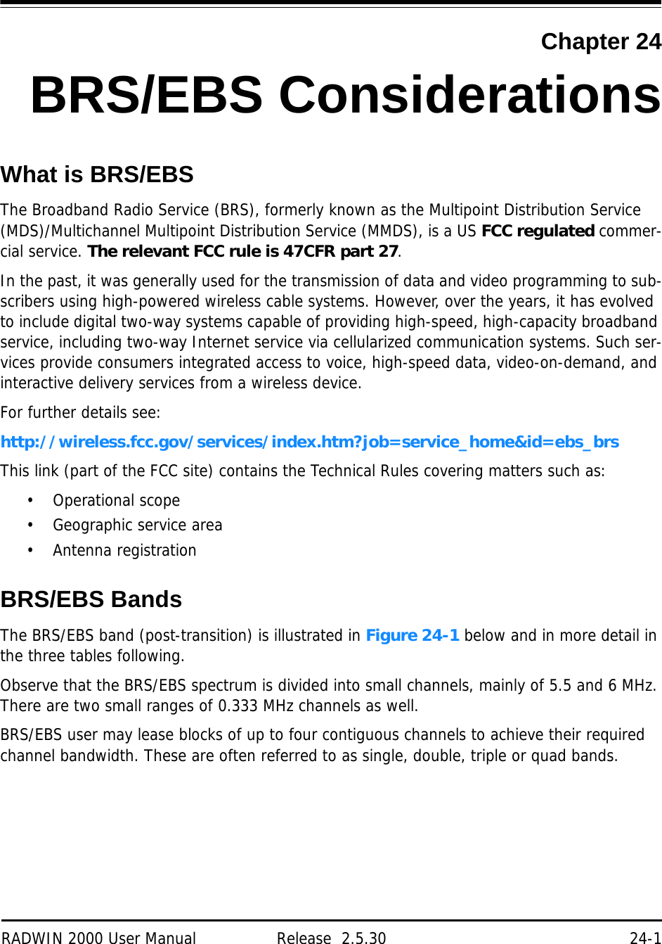
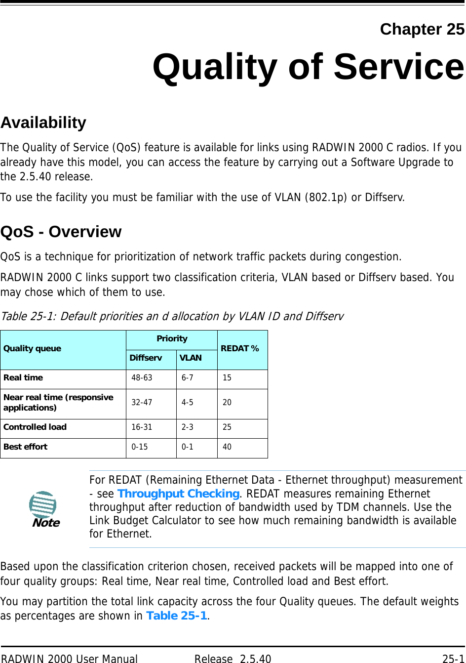
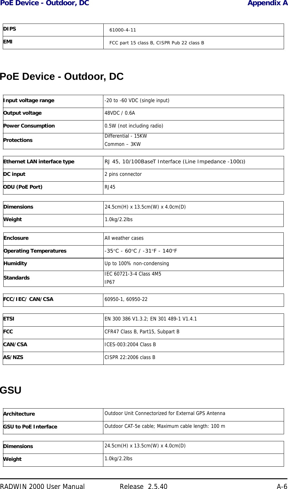
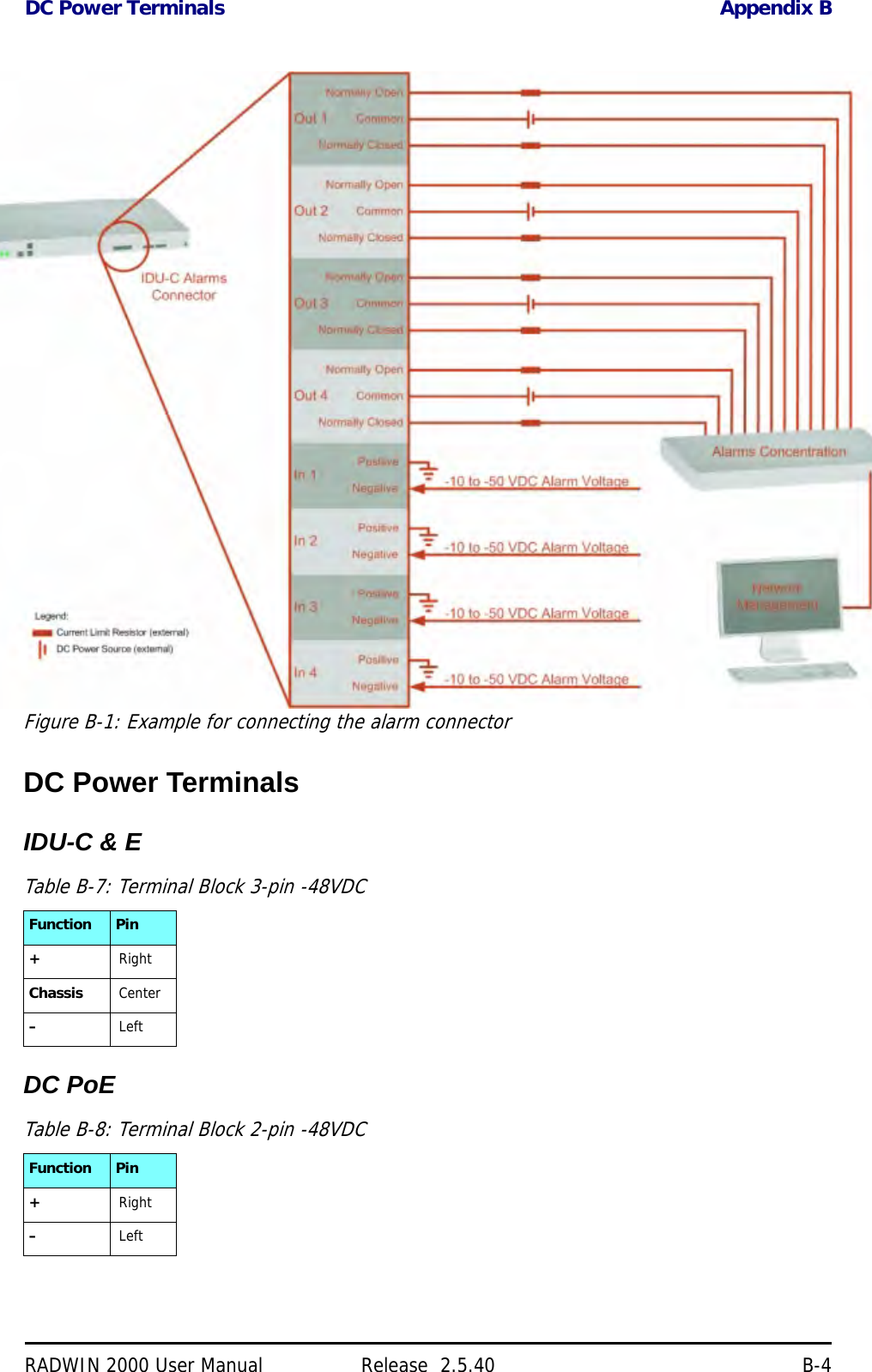
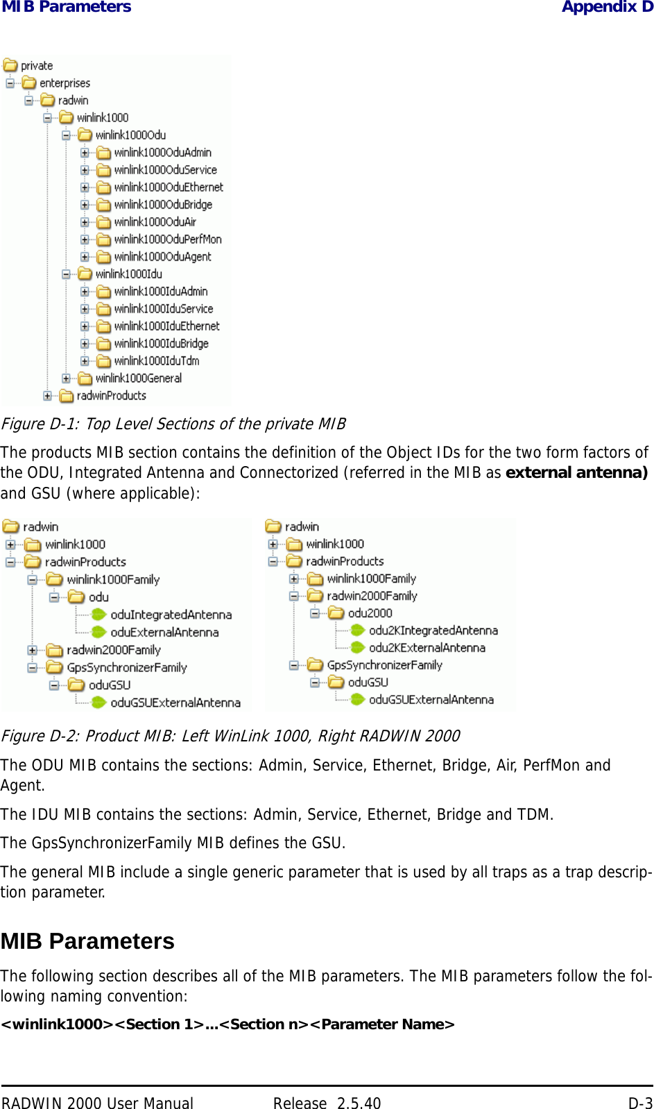
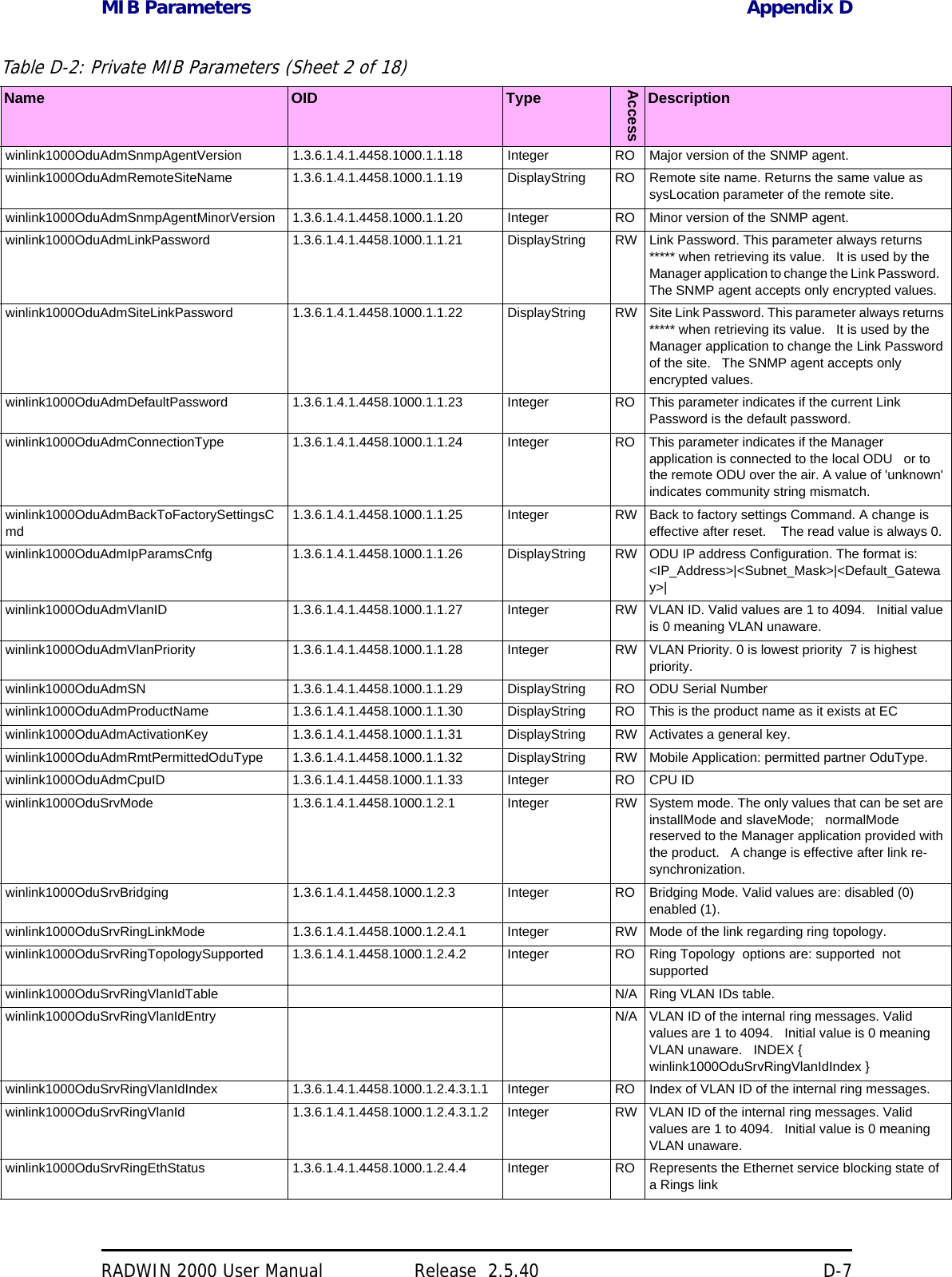
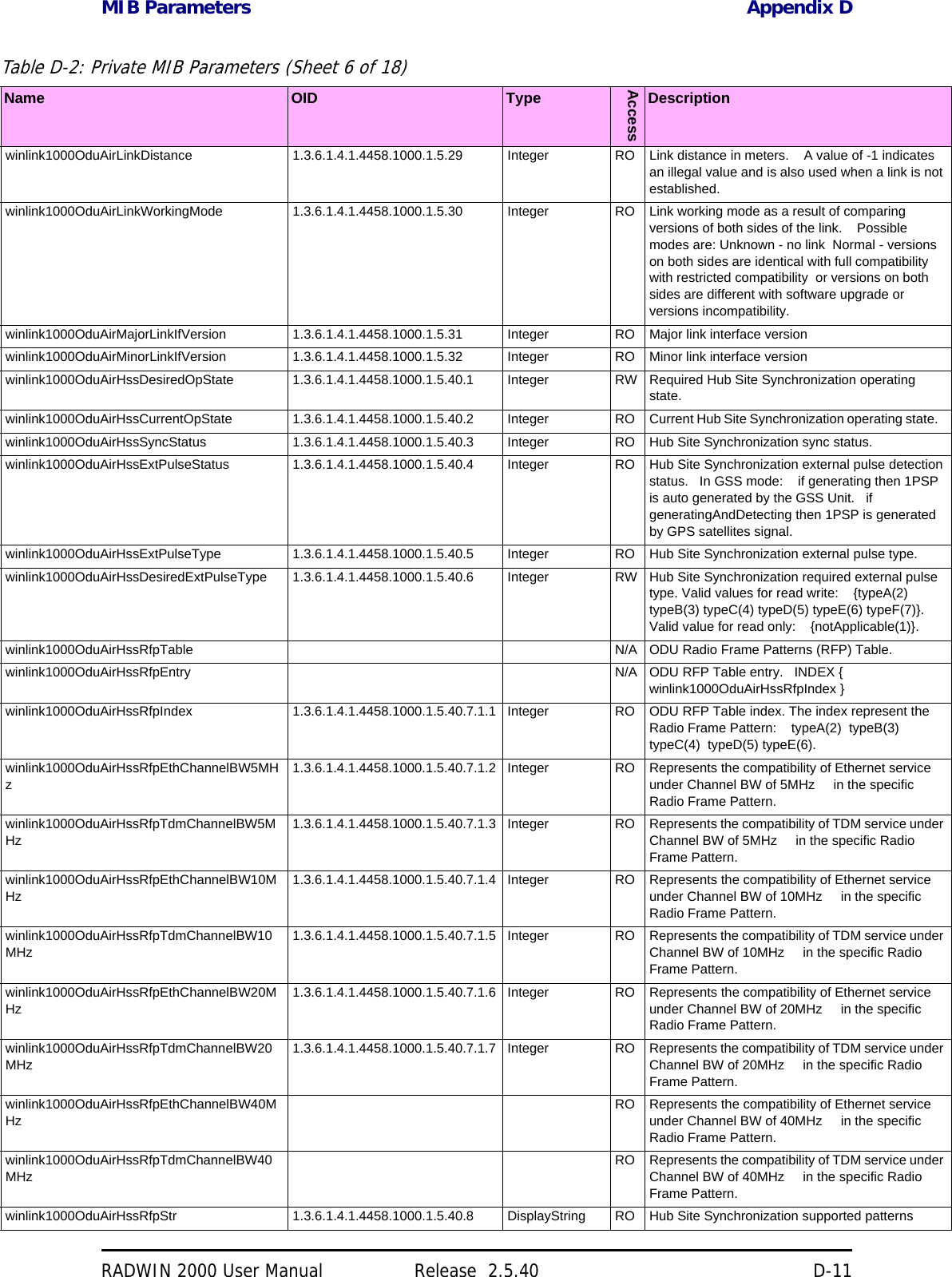
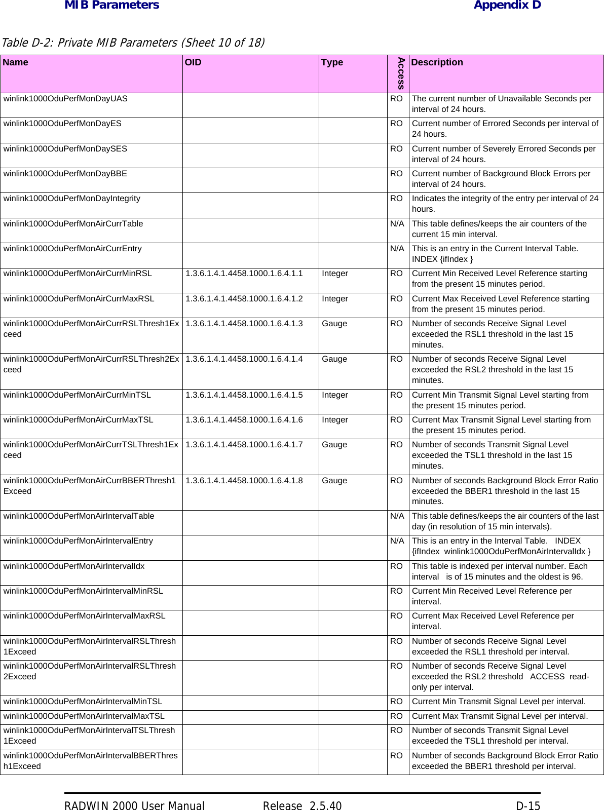
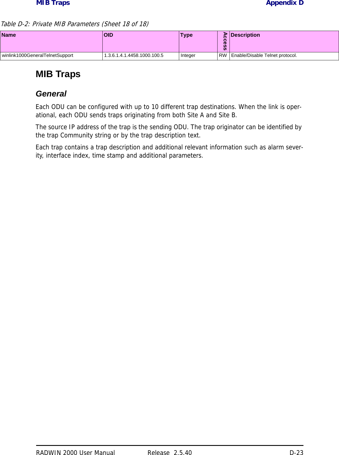
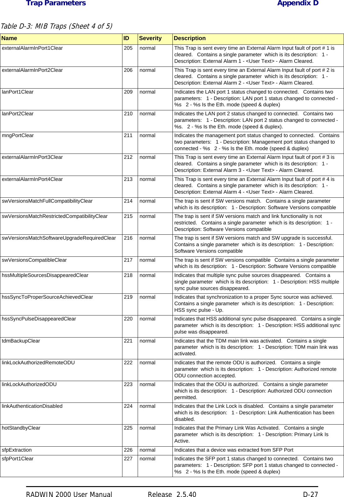
![Regulatory Considerations for 3.650-3.675 GHz FCC/IC part 90 sub part Z Chap-RADWIN 2000 User Manual Release 2.5.40 20-8Transmission power optionsTable 20-1shows the extent of compliance by RADWIN 2000 C products to FCC/IC power limits, having regards to antenna type and transmission power options.Higher Transmission Power Options and Restrictions:Table 20-2 defines the maximum transmission power and EIRP limits for the specified fre-quency and channel bandwidths.It specifies the power limits to be used by the operator when assigning center frequencies.Table 20-1: FCC/IC compliance by antenna and transmission powerMeasuredFrequency PowerAntenna Nominal CBWLow Center Frequency Channel [MHz]High Center Frequency Channel [MHz]Max Conducted Tx Power per Pole [dBm]Total Conducted Max Tx Power [dBm]Max EIRP [dBm]21dBi INT5 MHz 3653 3672 11.14 14.14 35.1410 MHz 3655 3670 14.46 17.46 38.4620 MHz 3660 3665 17.36 20.36 41.3621dBi EXT (22dBi-1dB feeder)5 MHz 3653 3672 11.14 14.14 35.1410 MHz 3655 3670 14.46 17.46 38.4620 MHz 3660 3665 17.36 20.36 41.3624dBi EXT (25 -1dB feeder loss)5 MHz 3653 3672 8.65 11.65 35.6510 MHz 3655 3670 11.36 14.36 38.3620 MHz 3660 3665 13.73 16.73 40.73Table 20-2: Higher Transmission Power LimitsNominalCBWLow Center Frequency Channel [MHz]High Center Frequency Channel [MHz]Max Conducted Tx Power per Pole [dBm]Total Conducted Max Tx Power [dBm]Max EIRP[dBm]5 MHz 3653 3672 15.60 18.60 35.6010 MHz 3655 3670 18.69 21.69 38.693656 3669 22.00 25.00 38.5020 MHz 3660 3665 21.18 24.18 41.183661 3664 22.60 25.60 39.10](https://usermanual.wiki/Radwin/RW2025.User-Manual-Part-2/User-Guide-1437359-Page-78.png)
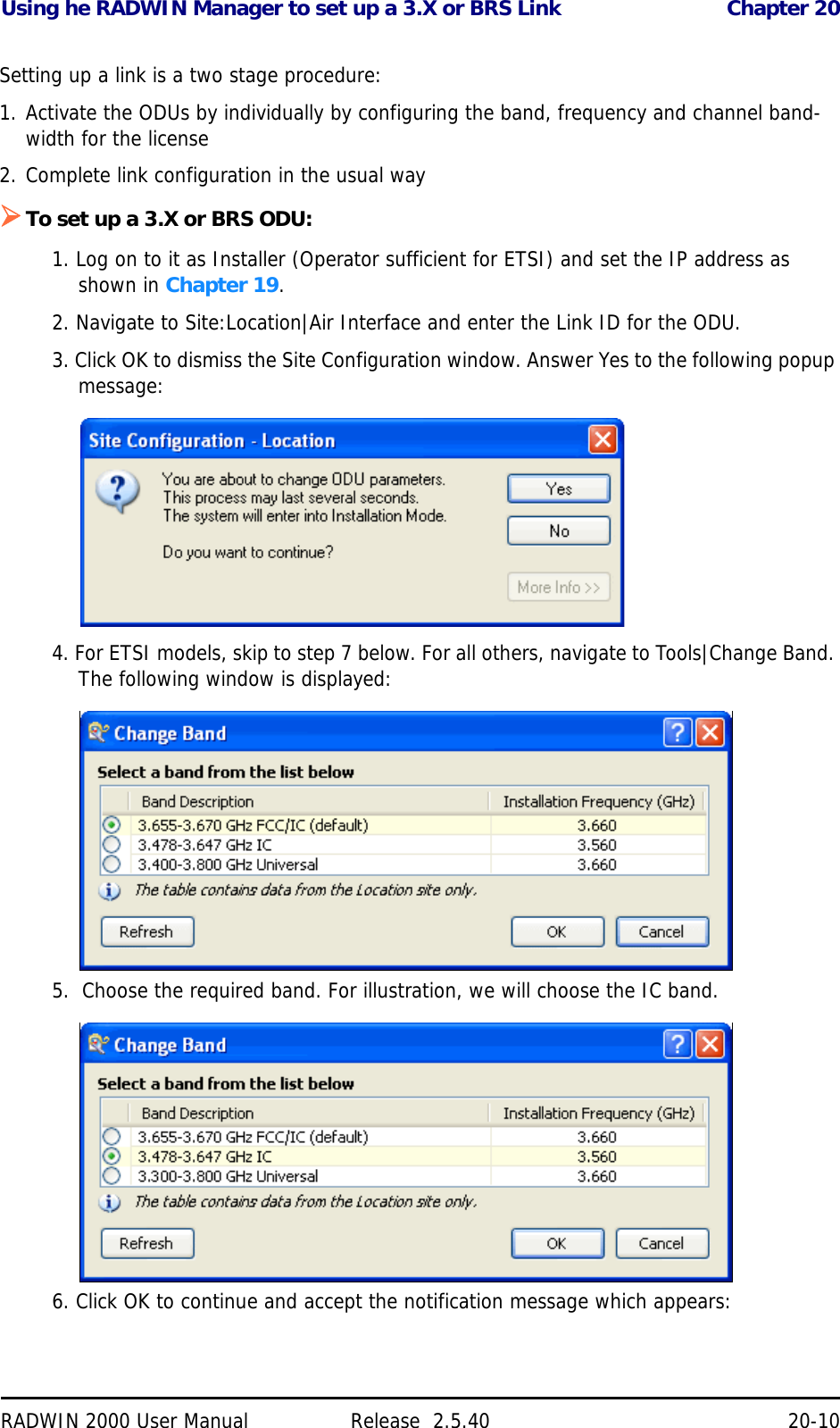
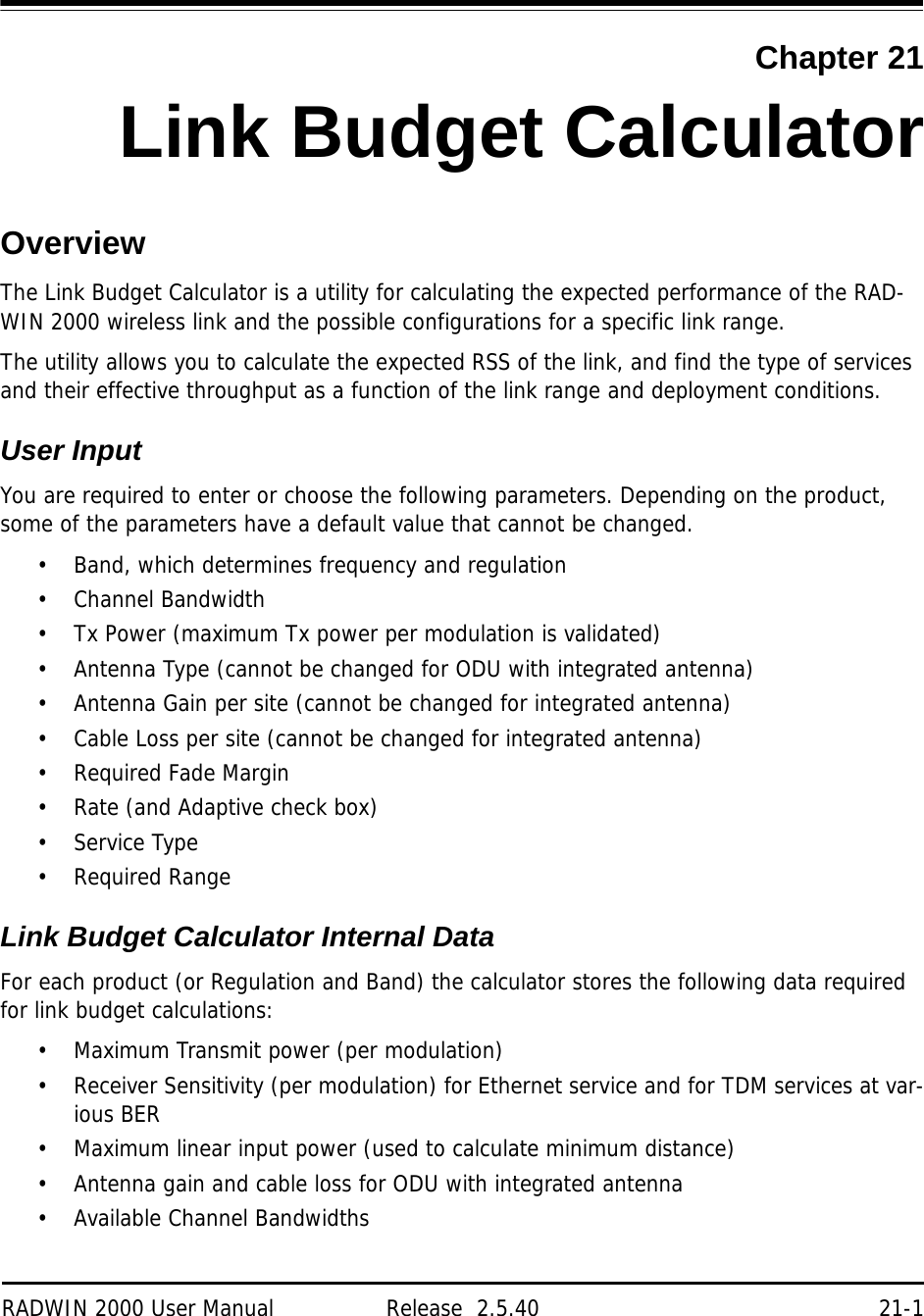
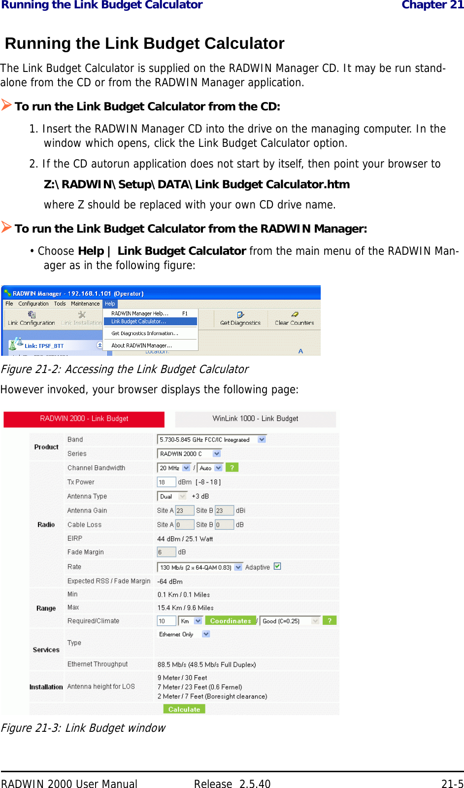
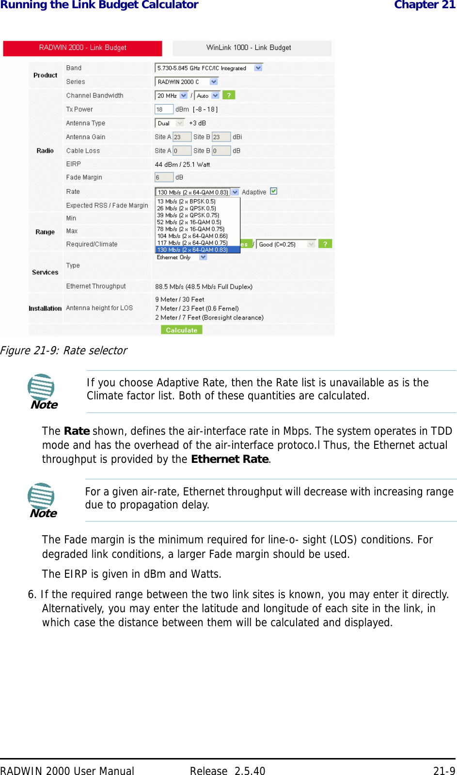
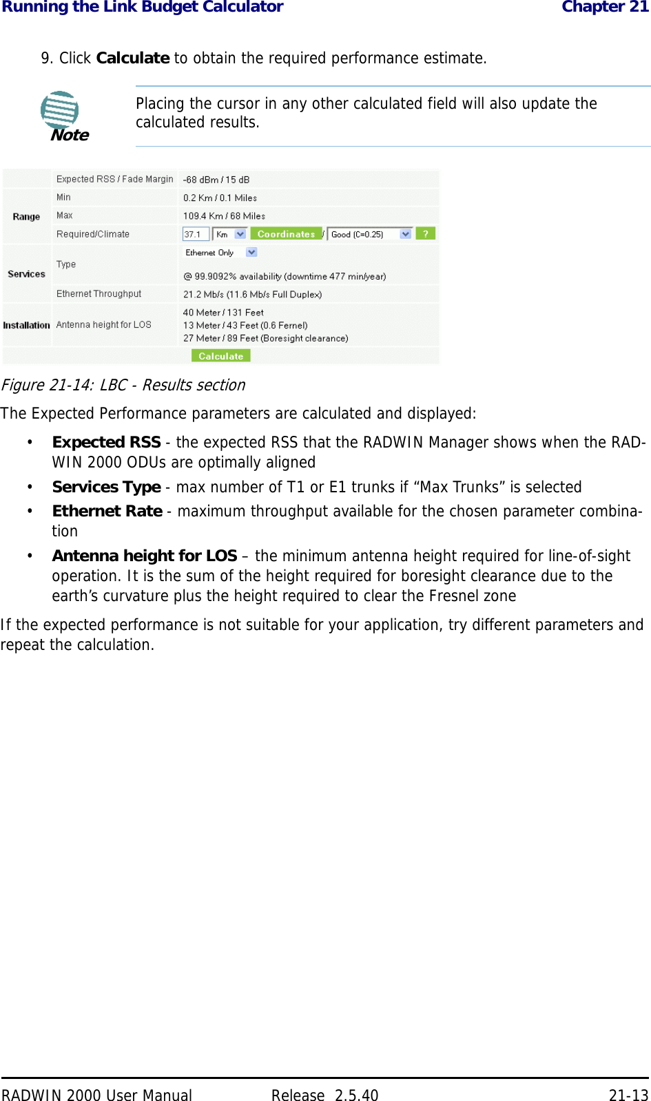

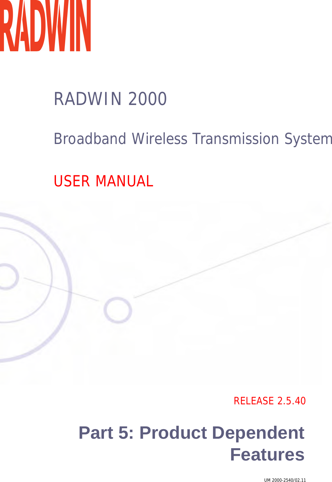
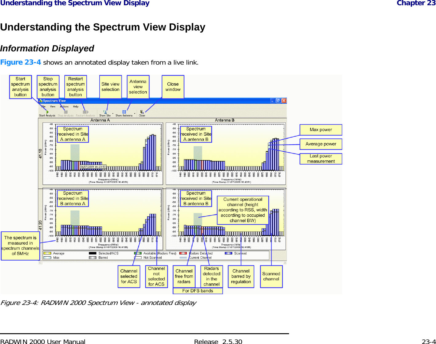
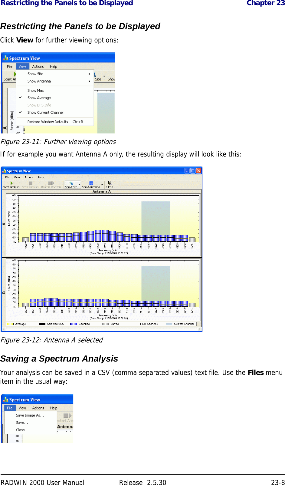
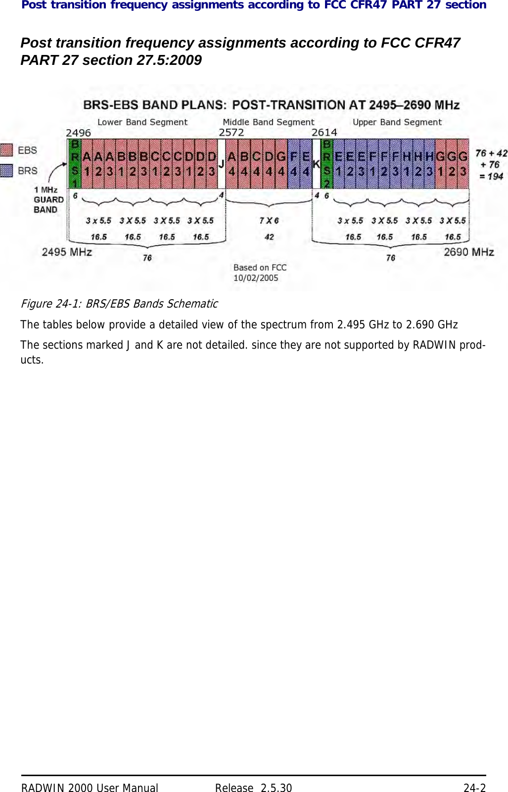
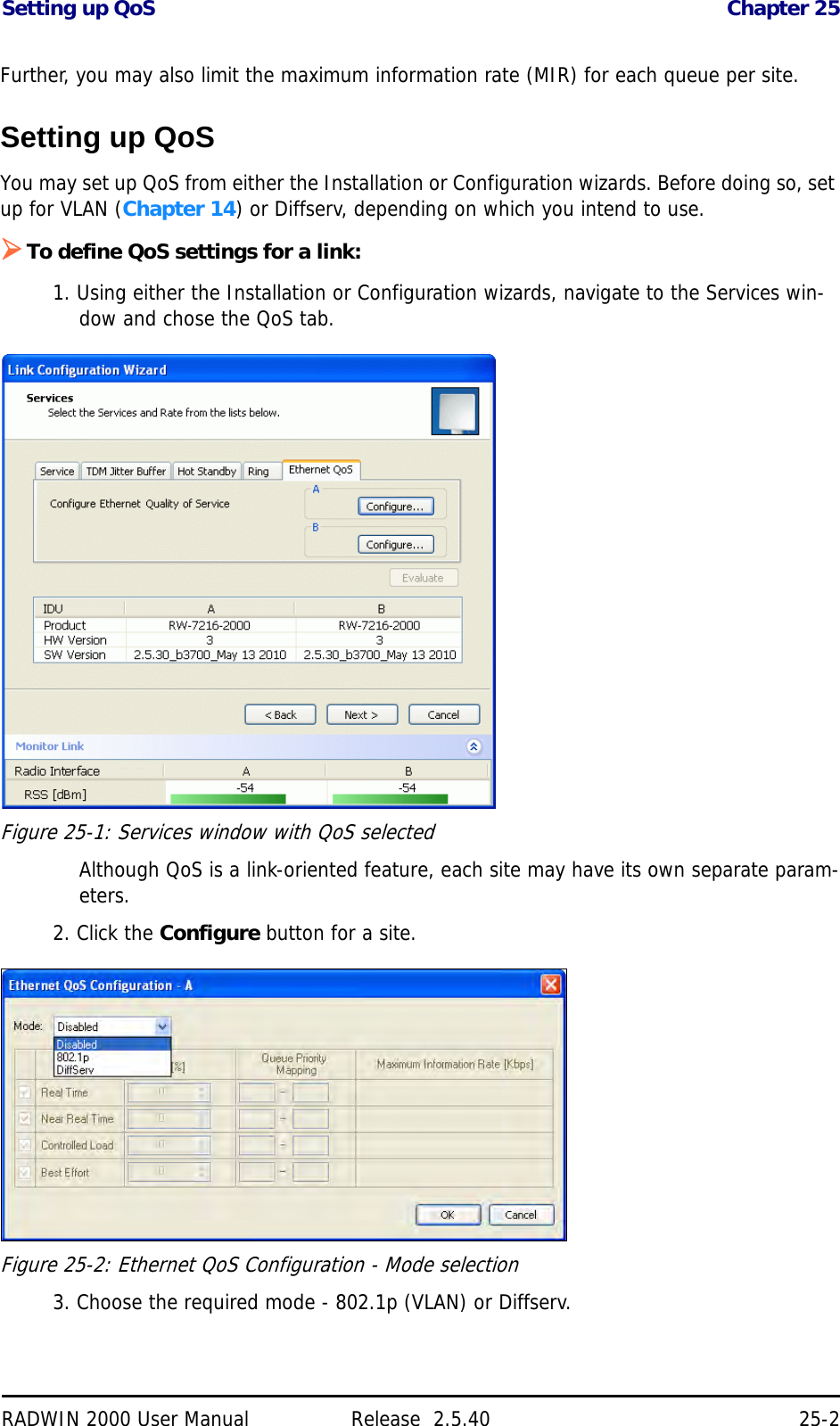
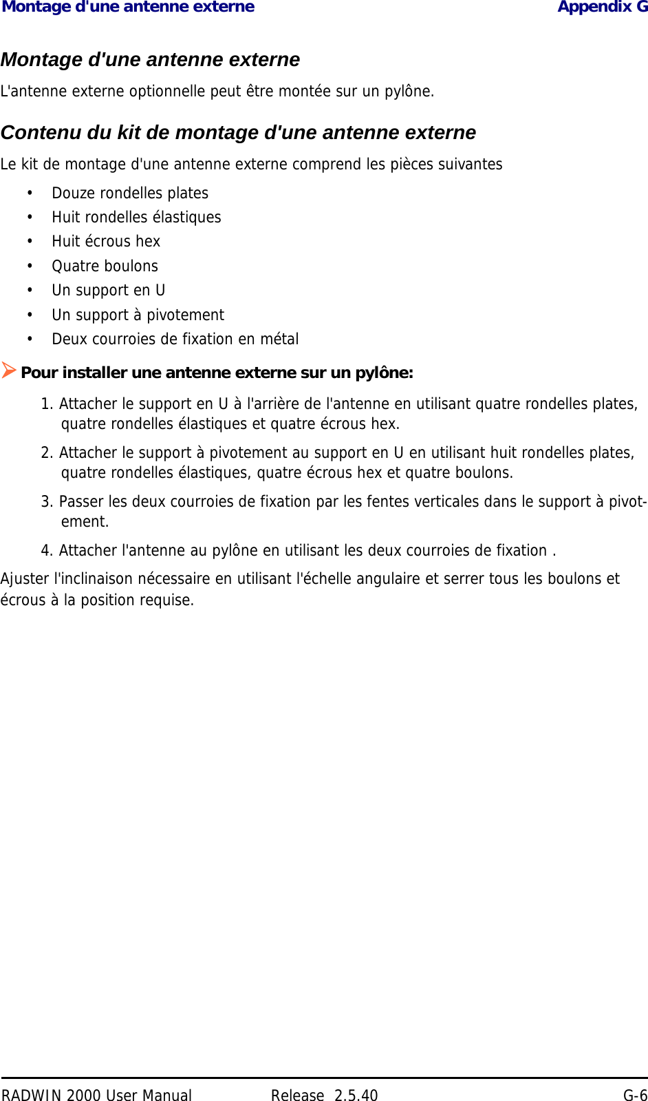
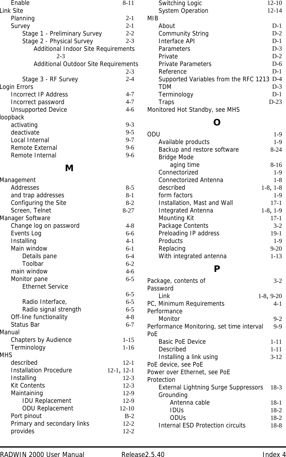
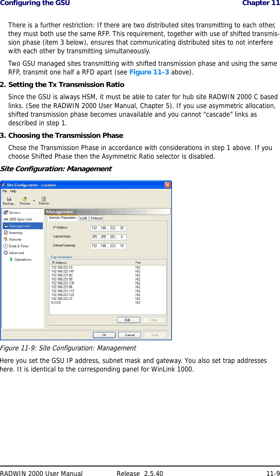
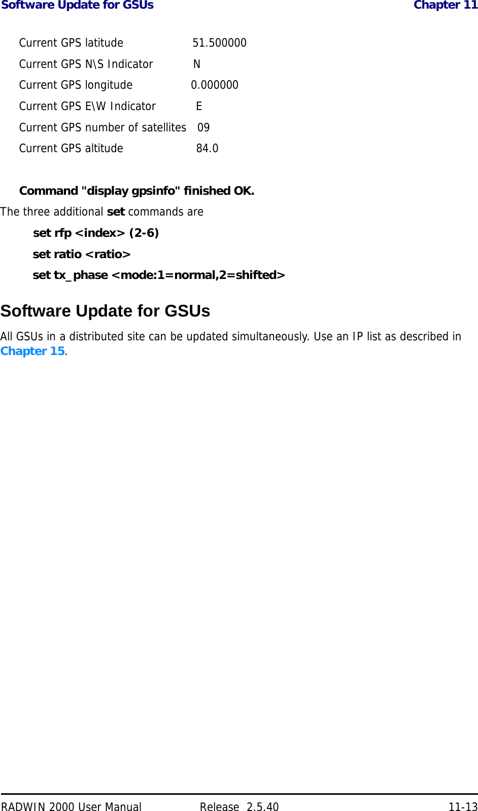
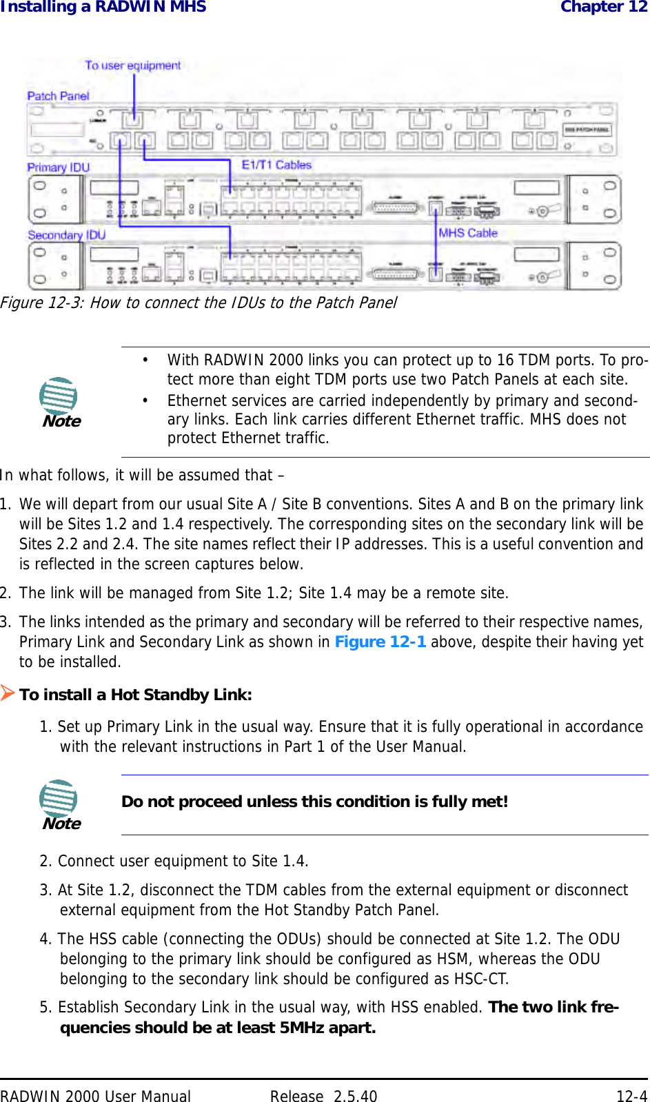
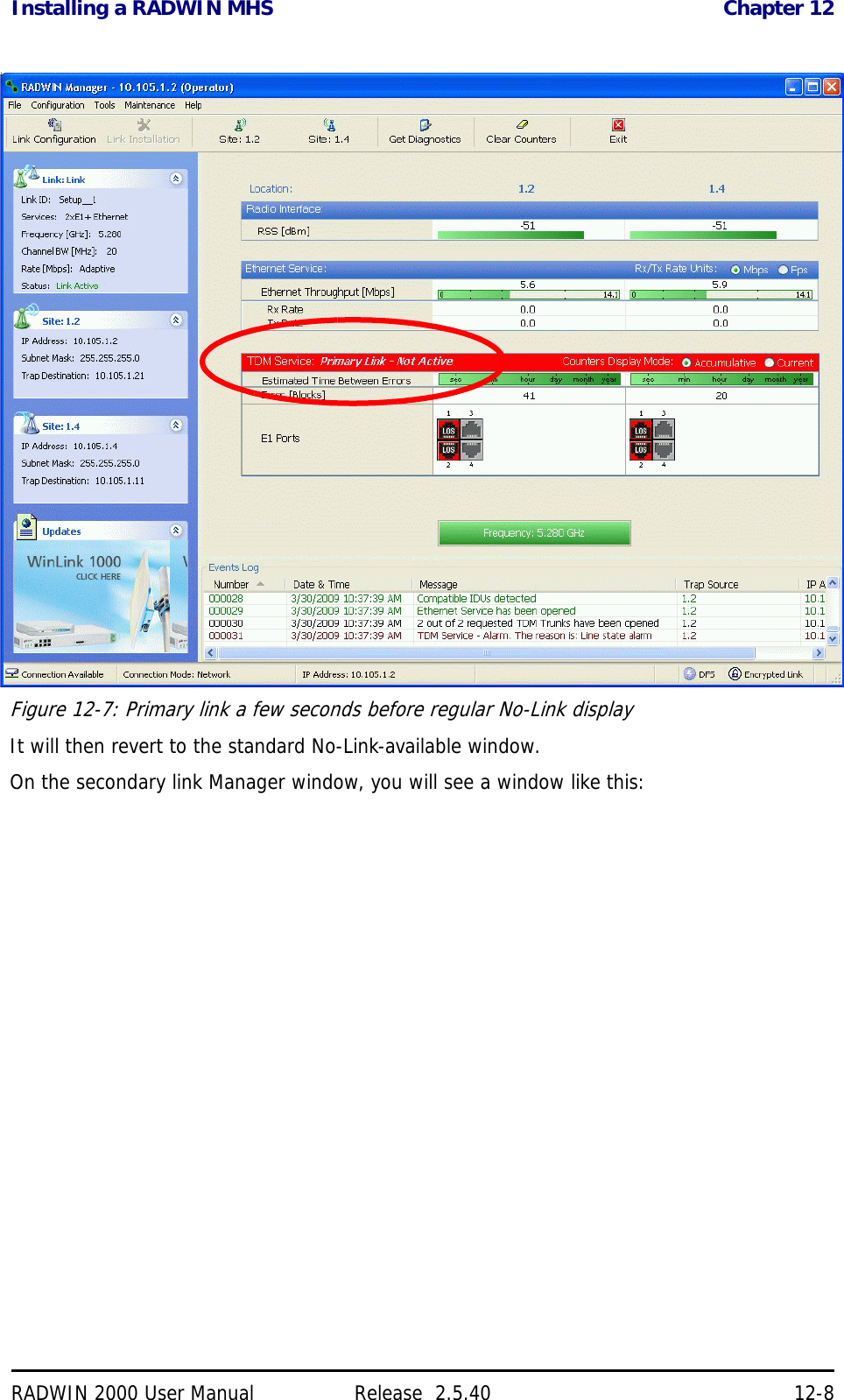
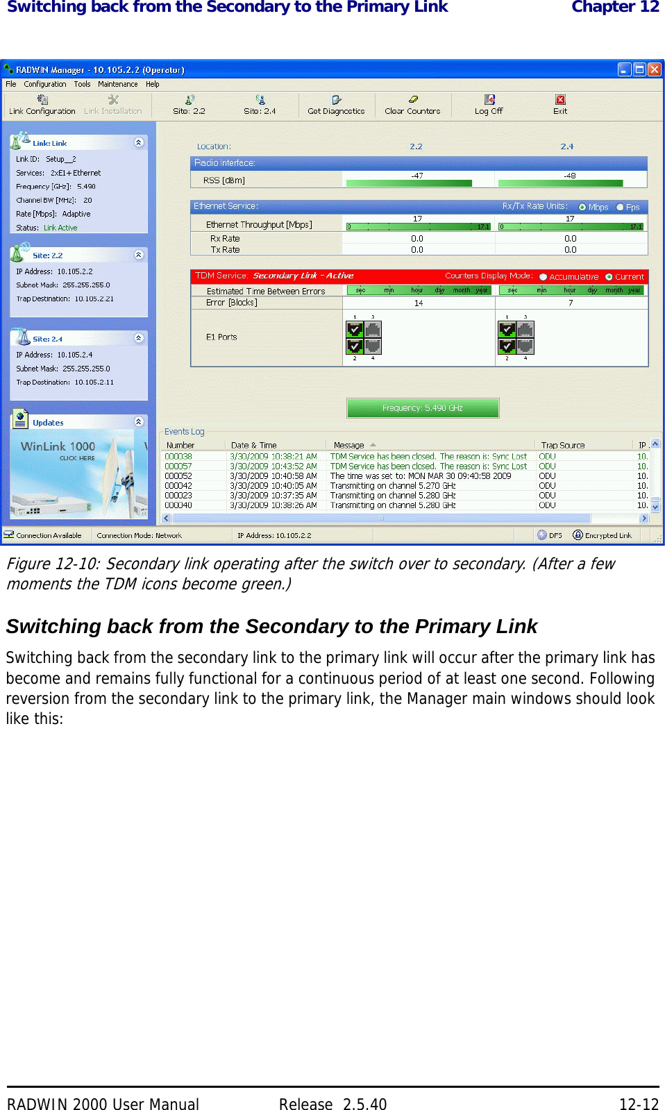
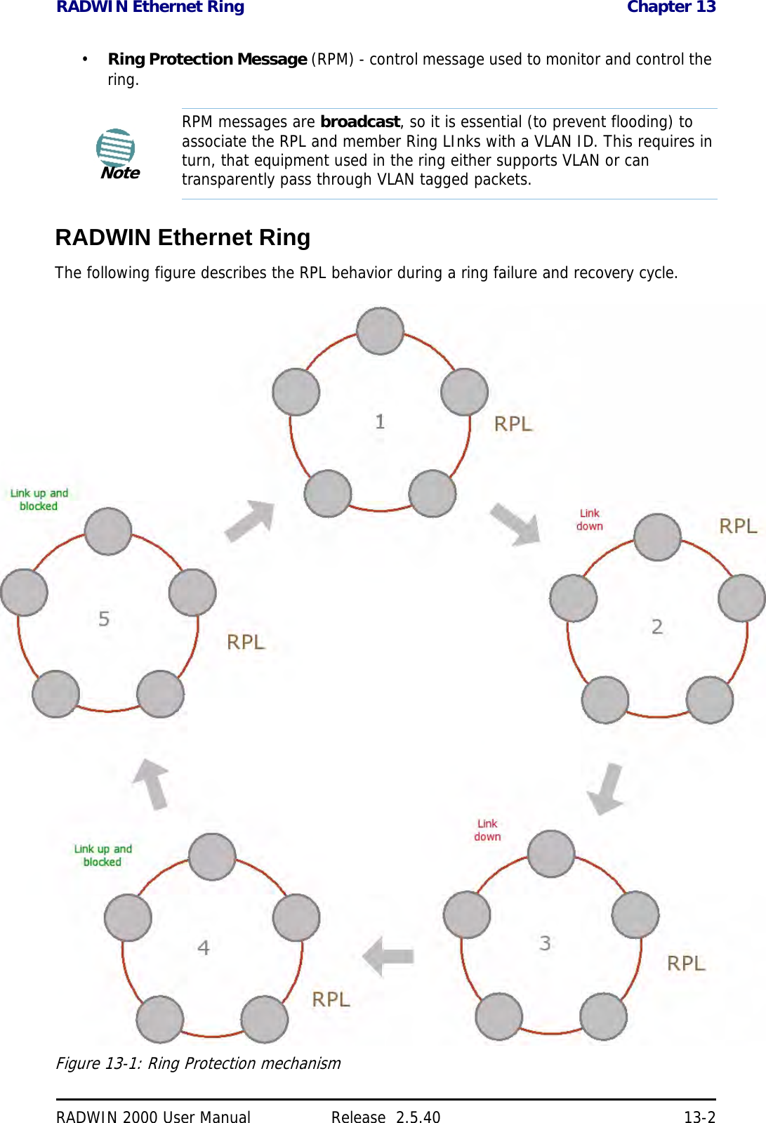
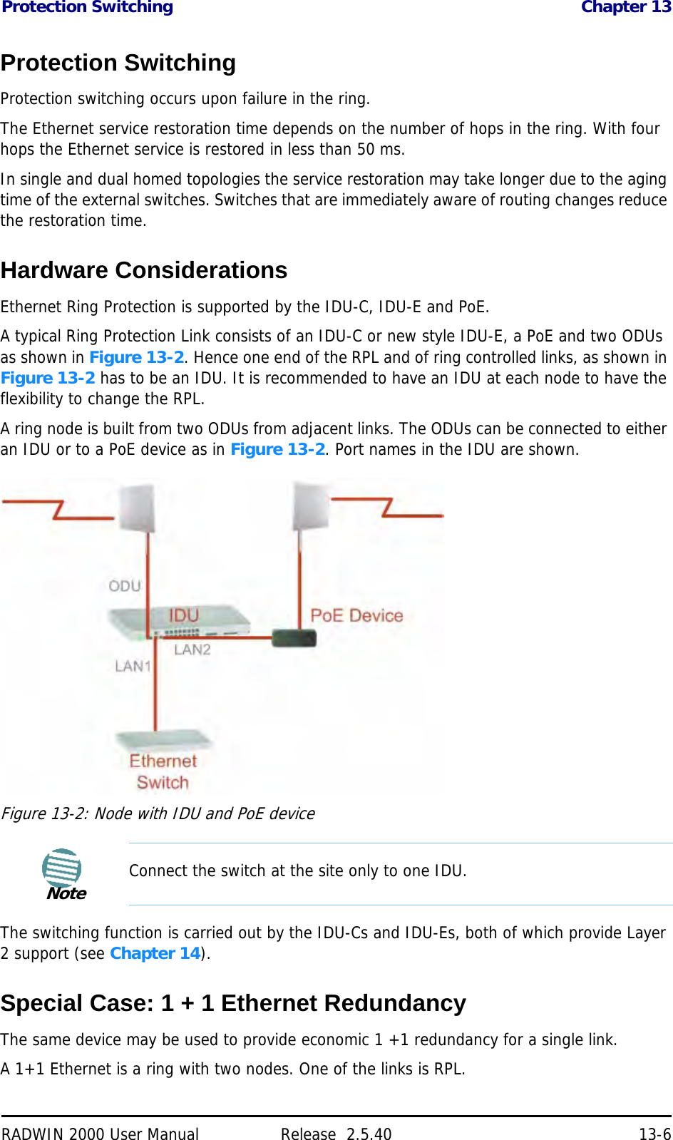
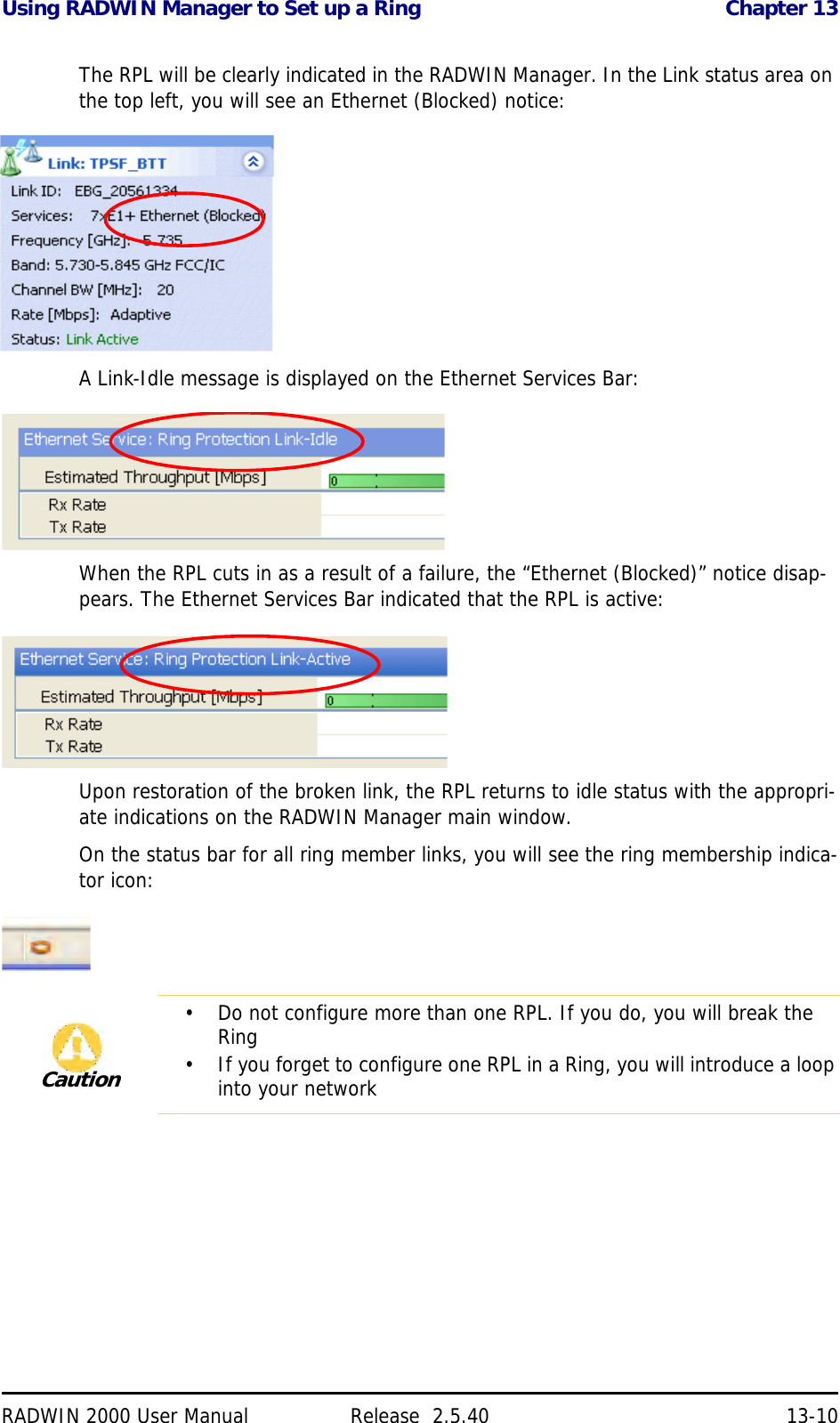
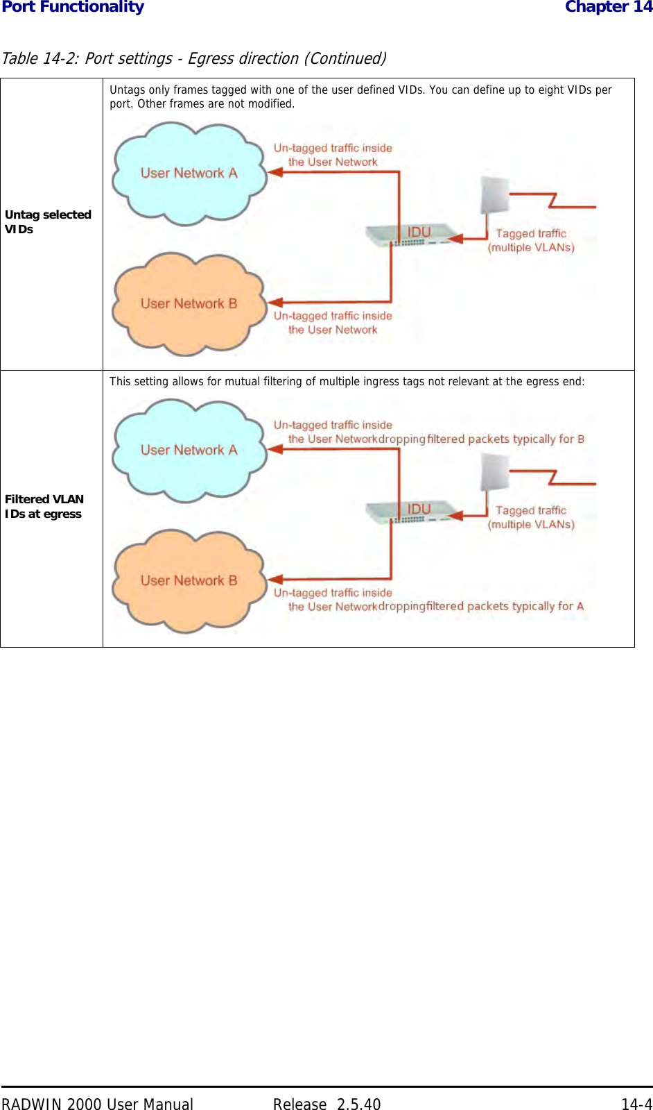
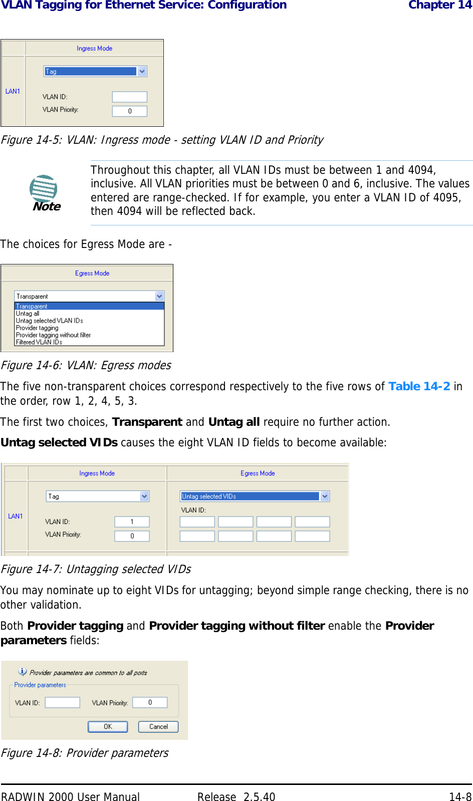
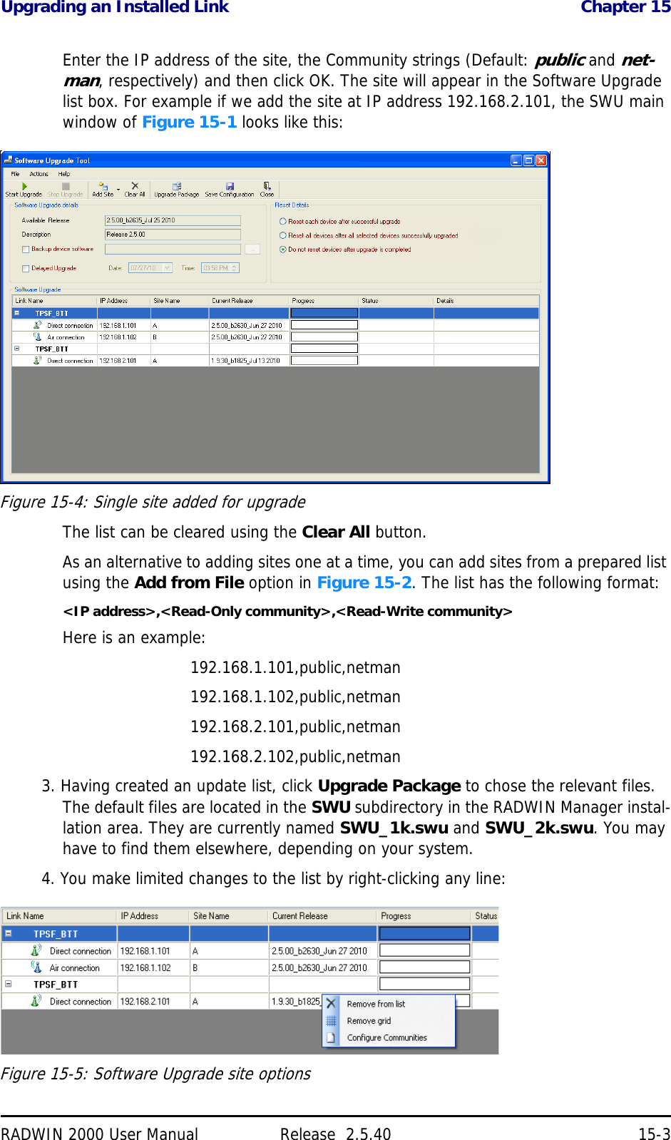
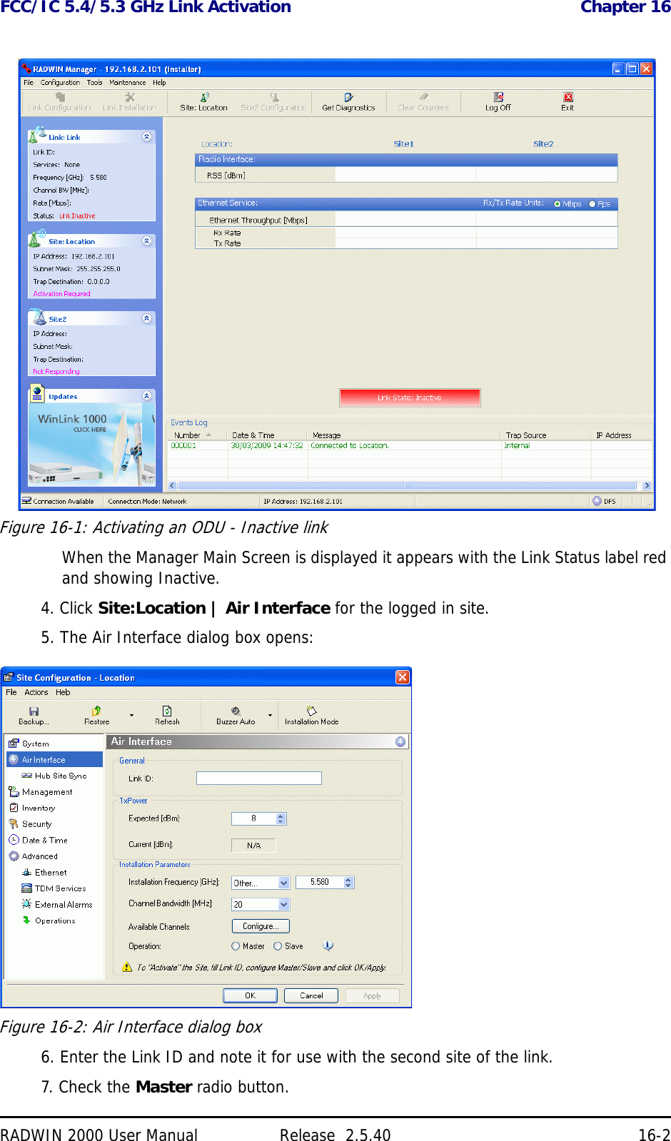
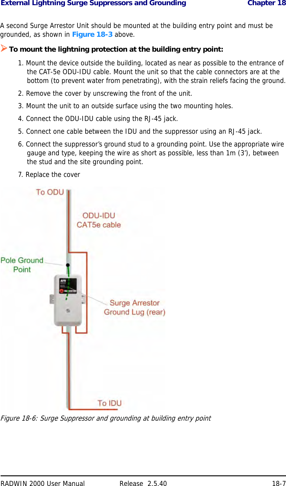
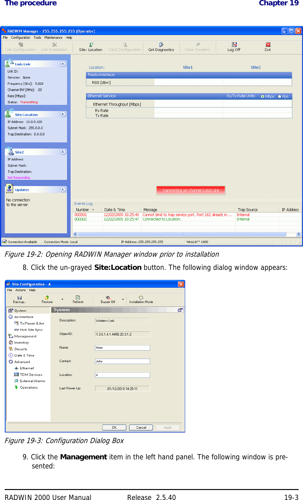
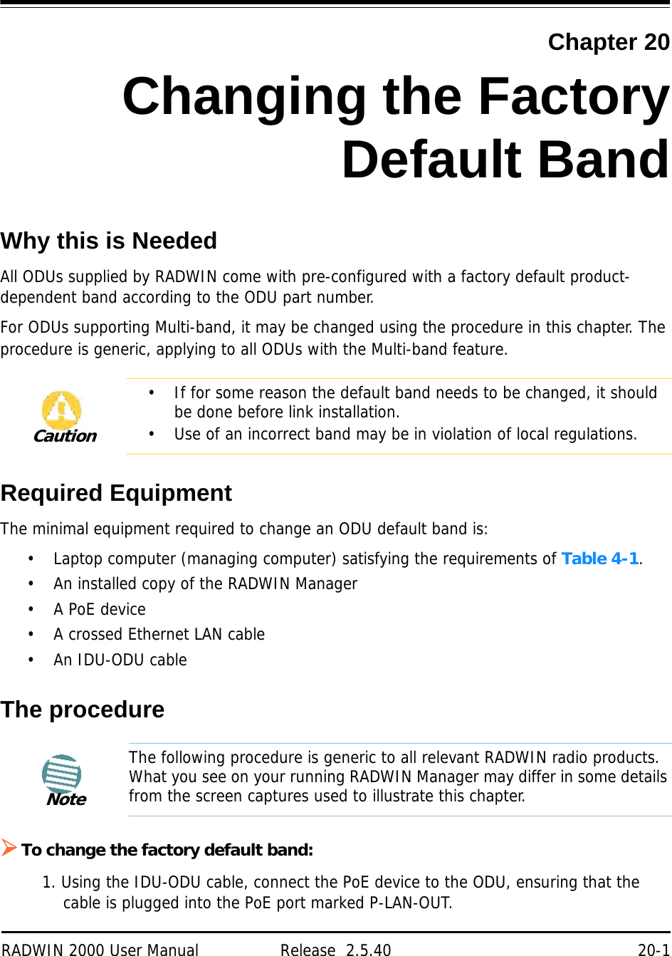
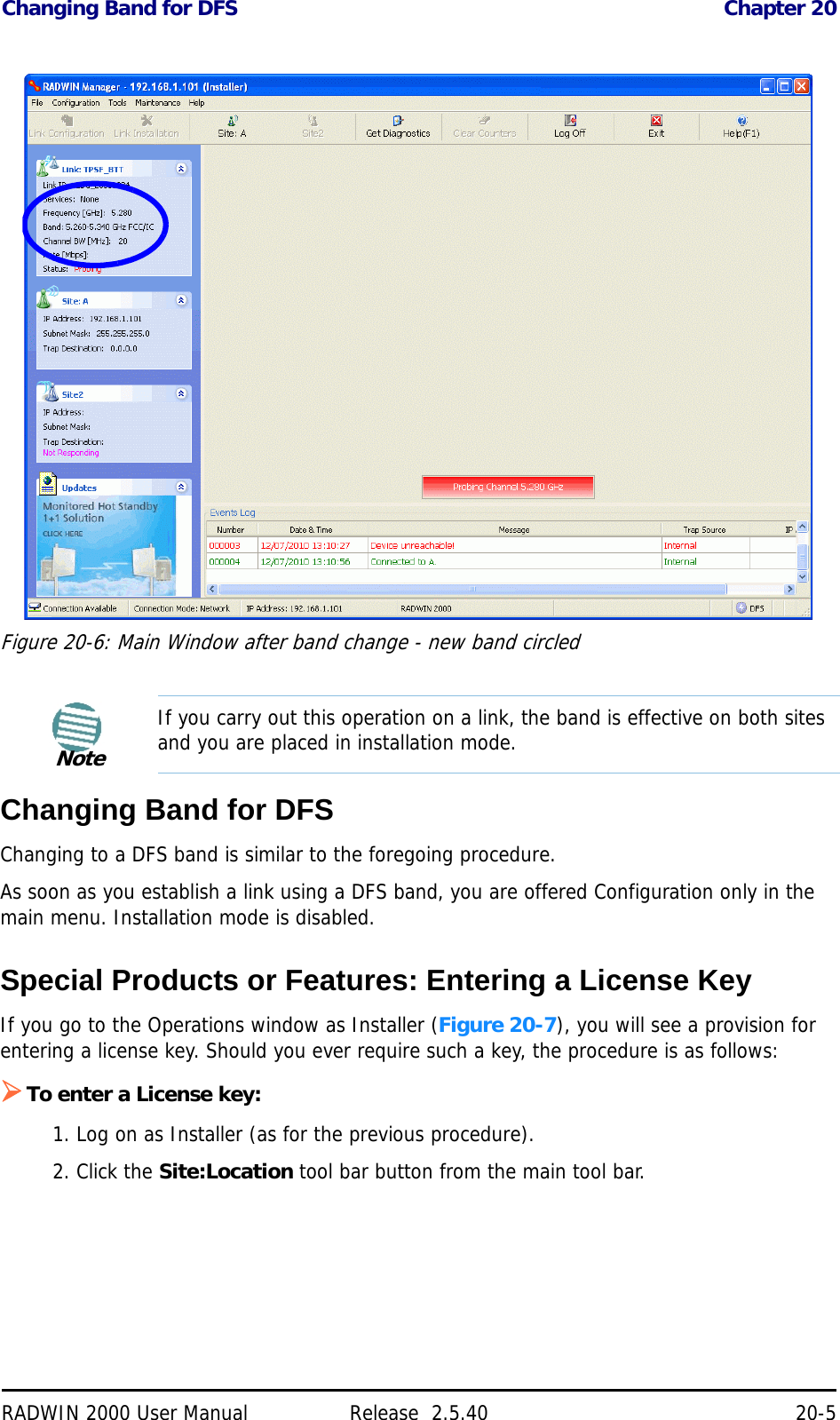
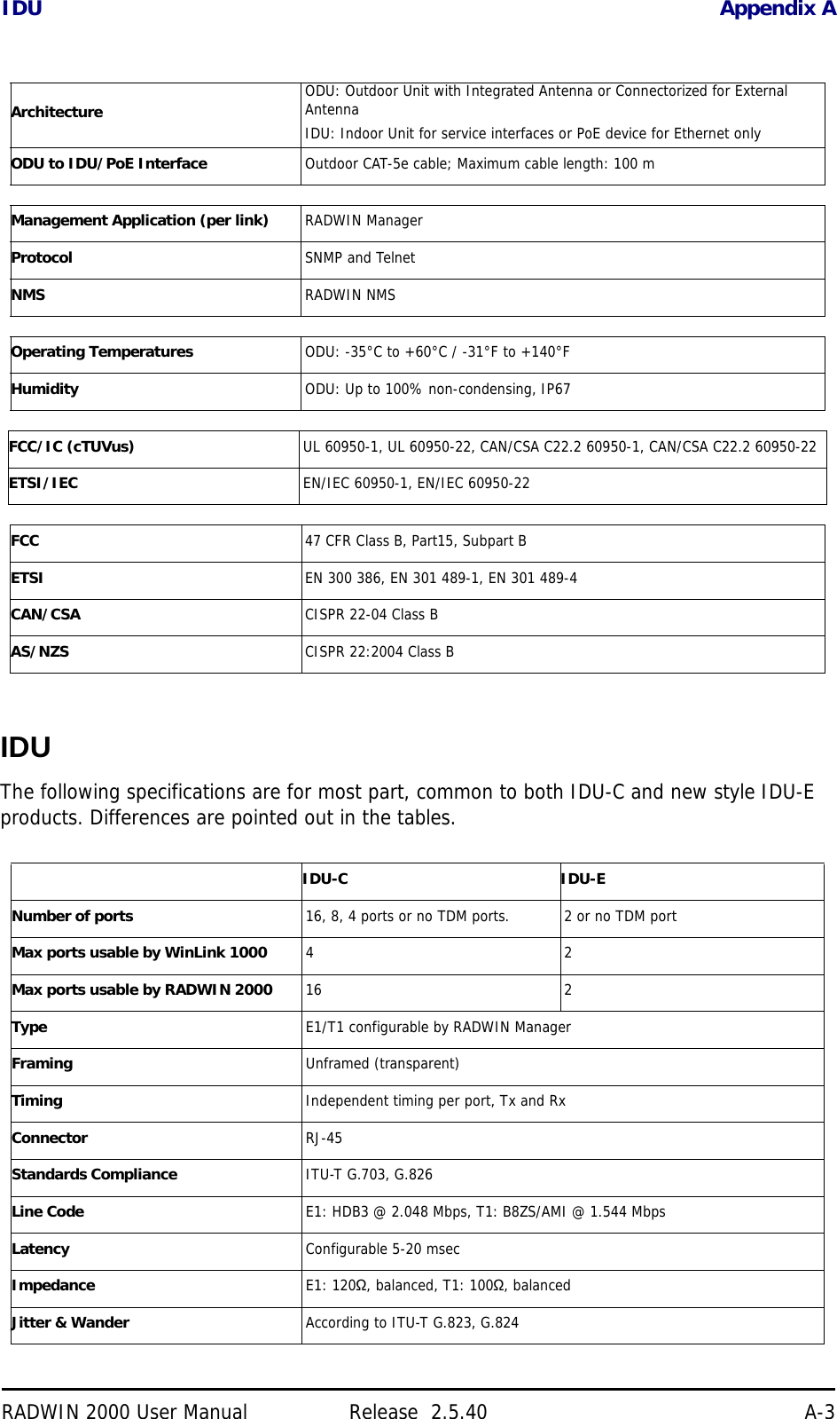
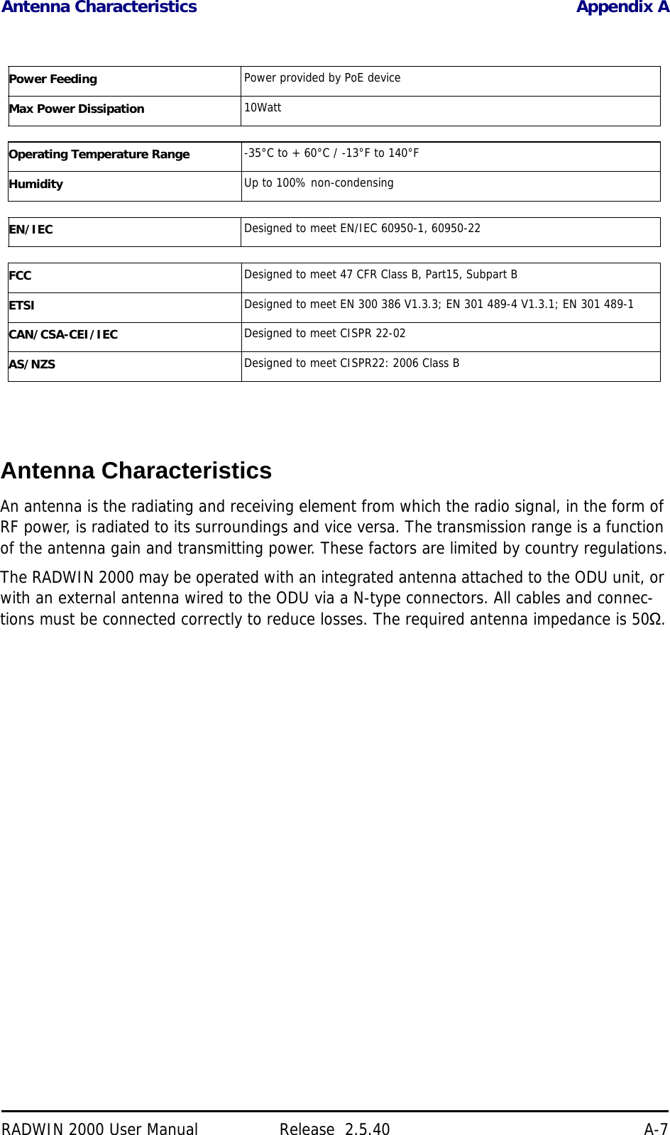
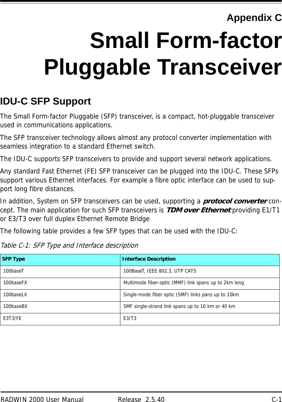
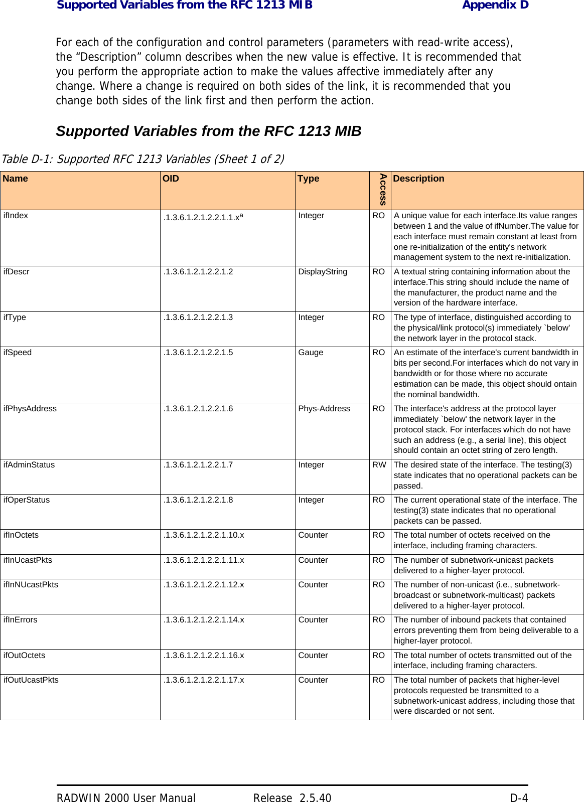
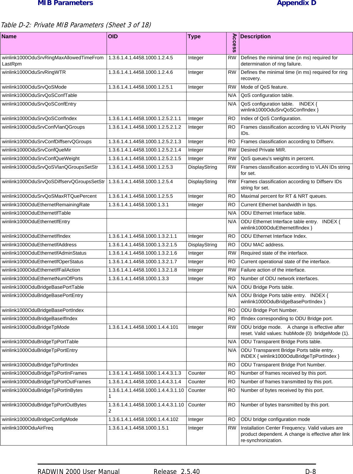
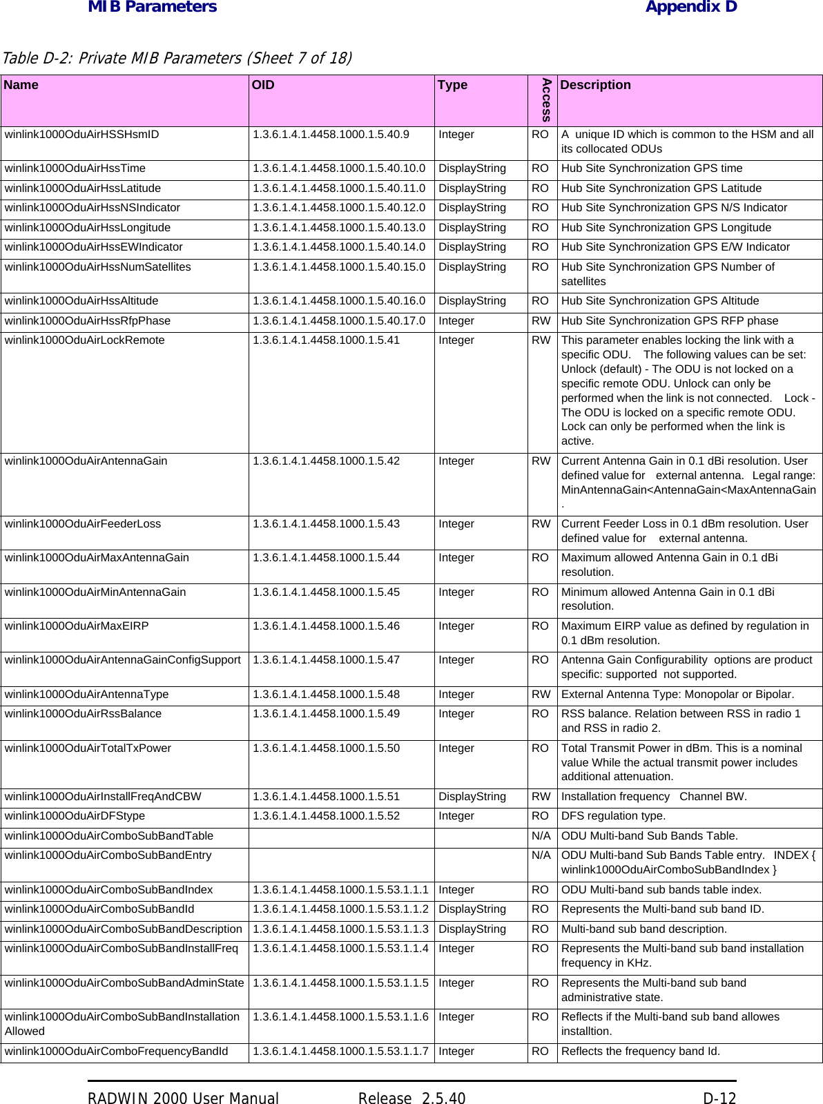
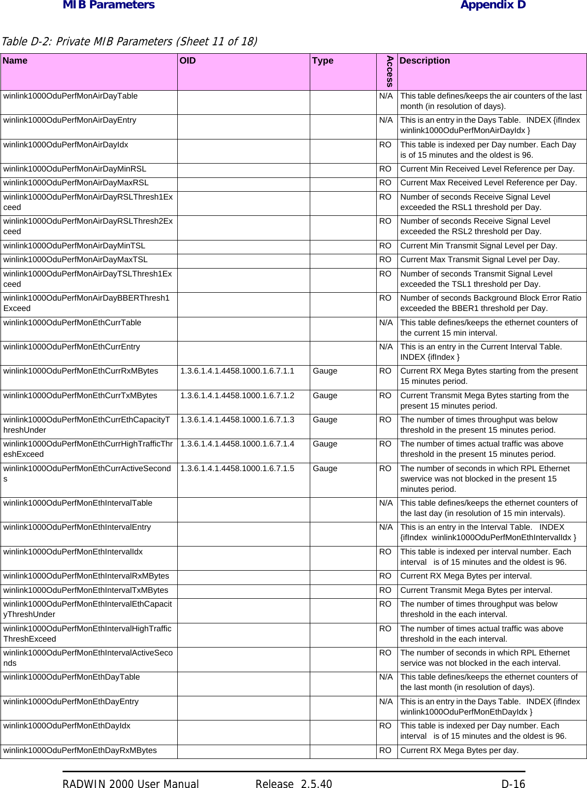
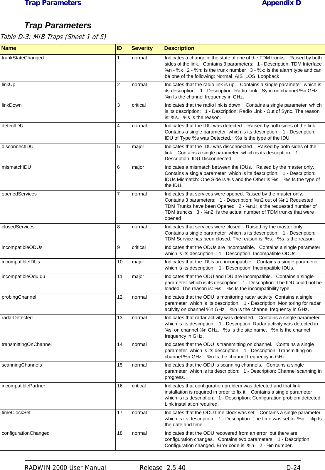
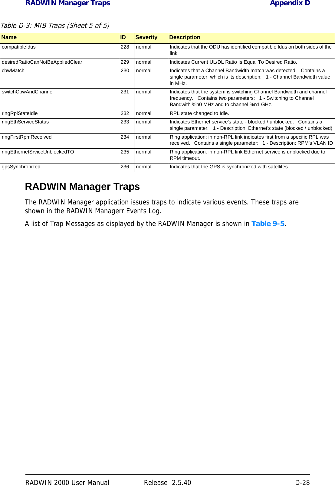
![RADWIN 2000 User Manual Release 2.5.40 A-1Appendix ATechnical SpecificationsScope of these SpecificationsThis appendix contains technical specifications for the major link components appearing in this User Manual. They are correct at the date of publication, but are intended for general background only. The latest authoritative and most up to date technical specifications are available as Data Sheets obtainable from RADWIN Customer Service.In any event, RADWIN reserves the right to change these specifications without notice.ODUCapacity• RADWIN 2000 C: Up to 16 E1/T1 services and up to 100 Mbps capacity (net throughput, full duplex)• RADWIN 2000 X: Up to 3 E1 or 4 T1 services up to 10Mbps capacity (net throughput , full duplex)• RADWIN 2000 L: Up to 50 Mbps capacity (net throughput, full duplex)• RADWIN 2000 PDH: Up to 16 E1/T1 services and up to 10 Mbps capacity (net throughput, full duplex. Requires an IDU-C or E, no PoE supportRange Up to 120 km / 75 milesRadio Modulation 2x2 MIMO-OFDM (BPSK/QPSK/16QAM/64QAM)Adaptive Modulation & Coding SupportedAutomatic Channel Selection SupportedDiversity SupportedSpectrum View SupportedDuplex Technology TDDError Correction FEC k = 1/2, 2/3, 3/4, 5/6Rate – Dual Antenna [Mbps] 13 26 39 52 78 104 117 130Rate – Single Antenna [Mbps] 6.5 13 19.5 26 39 52 58.5 65Modulation BPSK QPSK 16QAM 64QAMFEC [k=] 1/2 1/2 3/4 1/2 3/4 2/3 3/4 5/6Max Tx Power [dBm] for 4.8 – 6 GHz 25 24 21 19 18Max Tx Power [dBm] for 2.4 GHz 26 25 24 24 21 20Max Tx Power [dBm] for 2.5 GHz (BRS) See Table 24-3](https://usermanual.wiki/Radwin/RW2025.User-Manual-Part-2/User-Guide-1437359-Page-121.png)
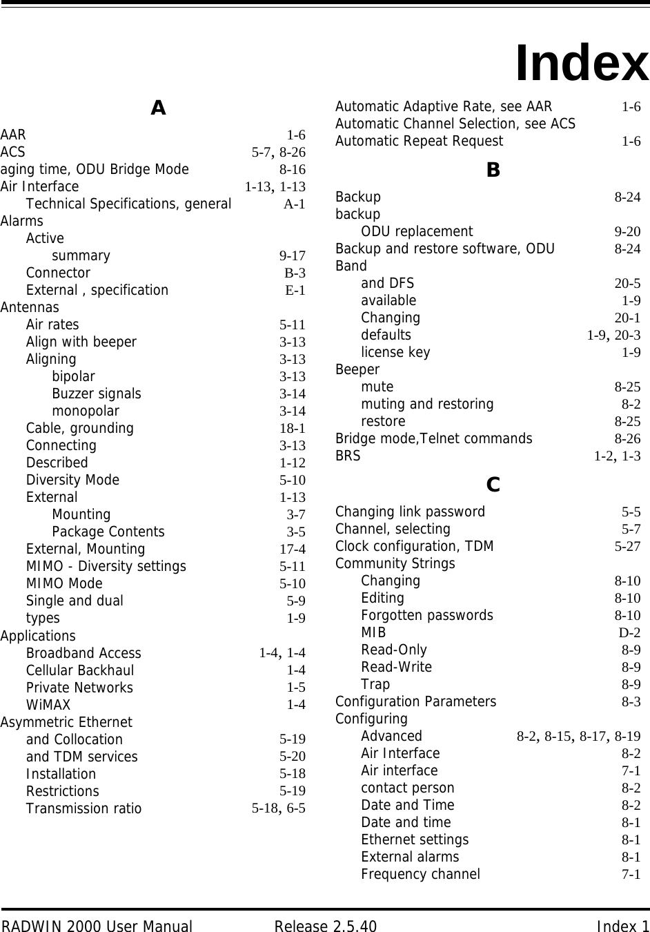
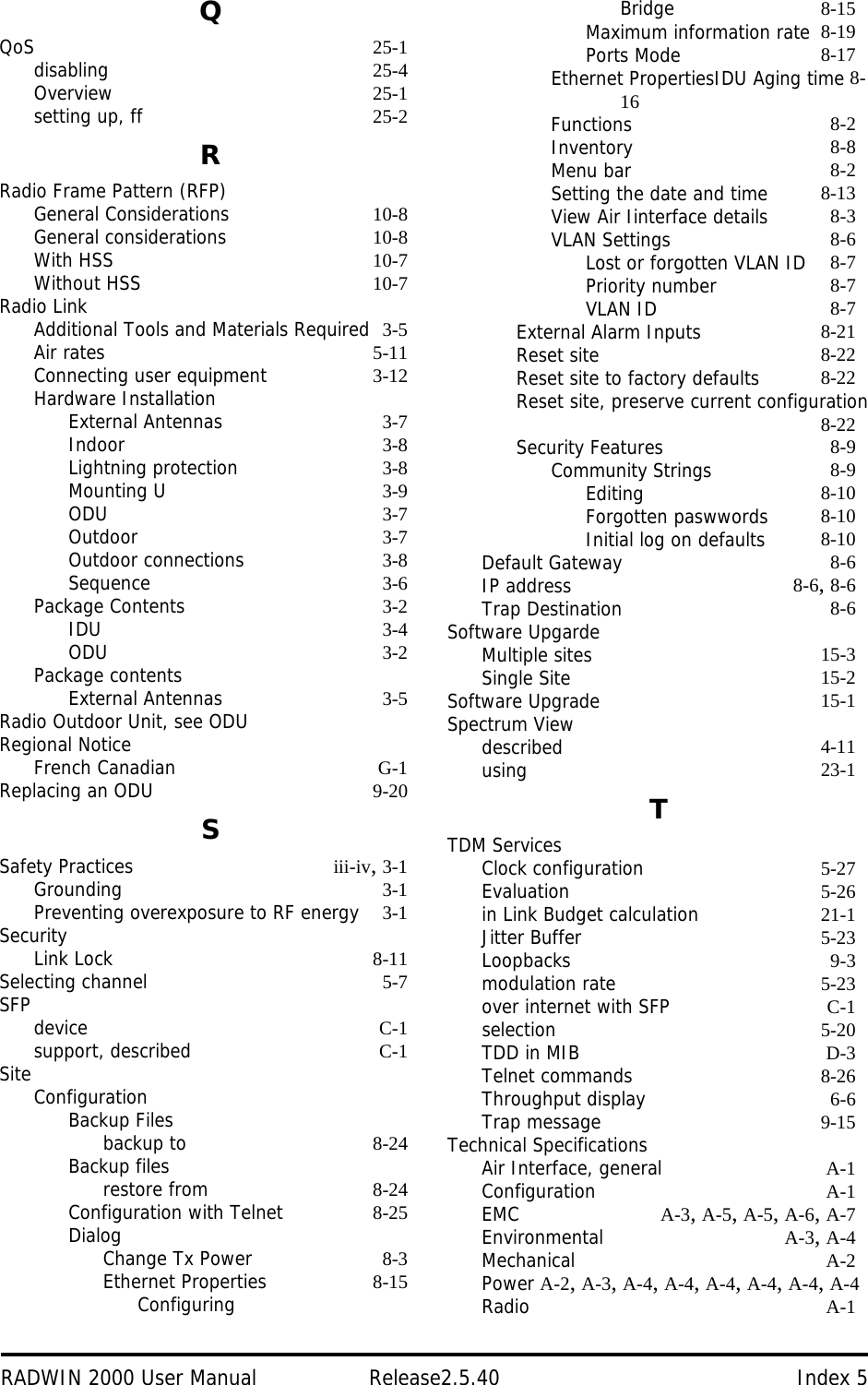
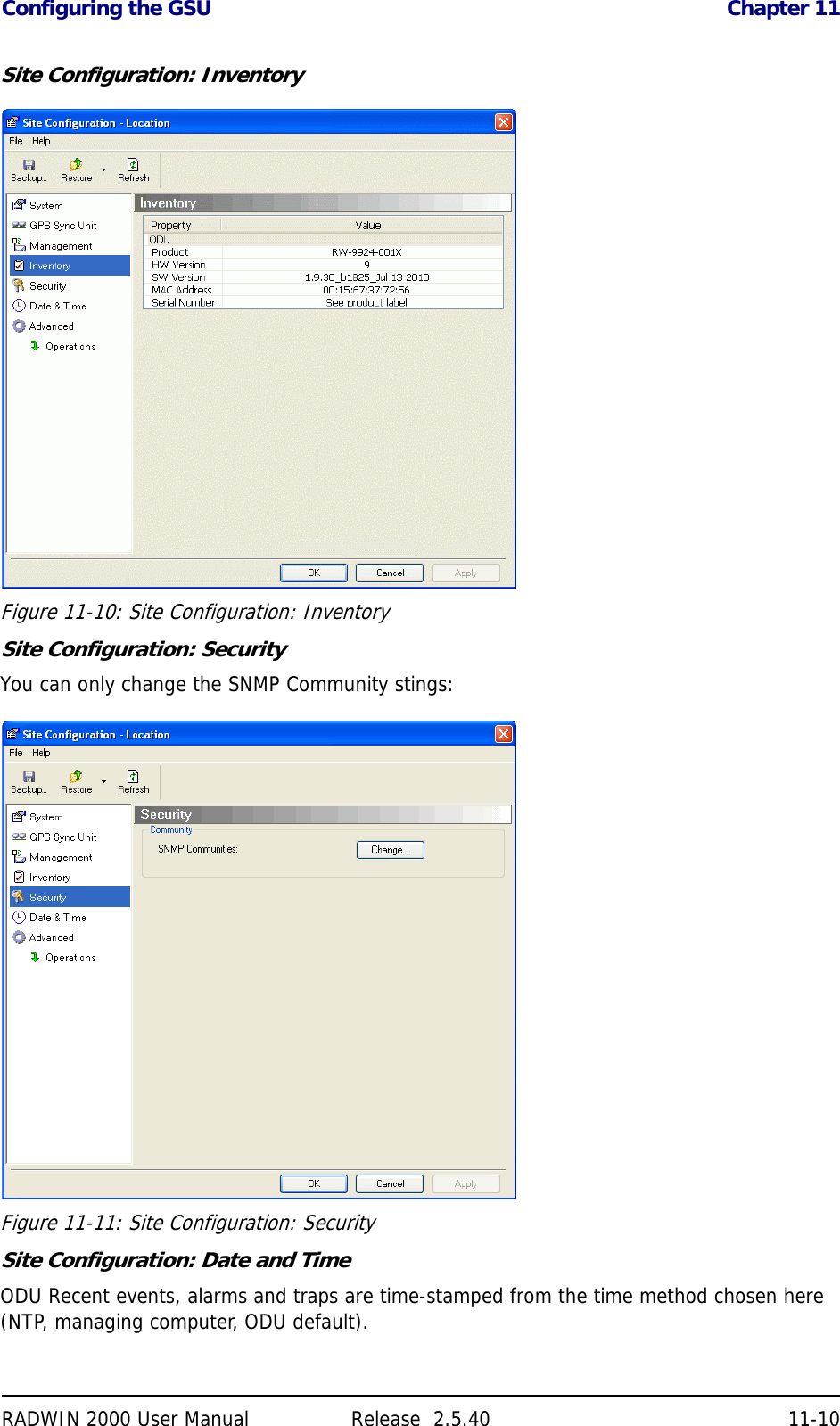
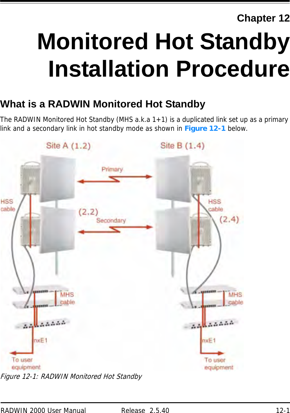
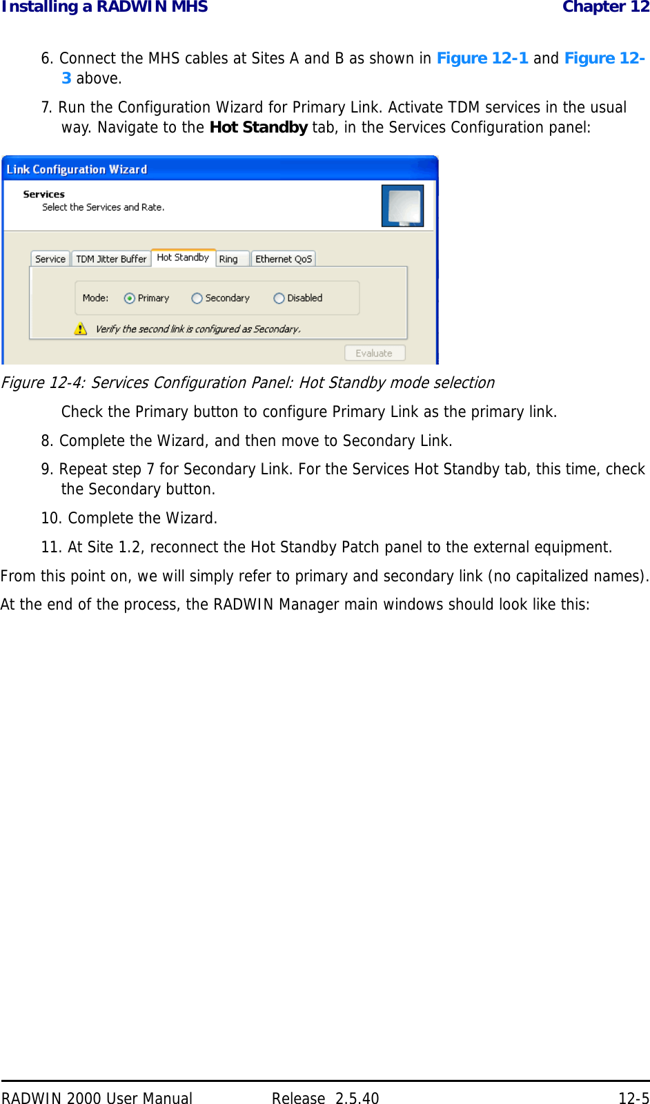
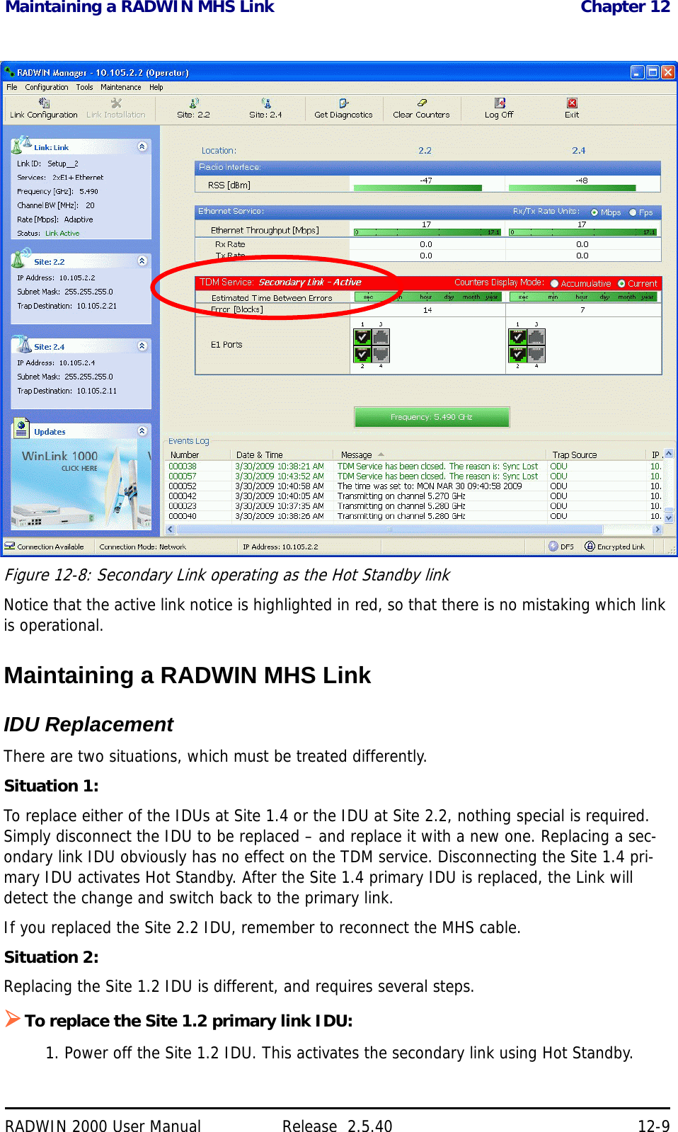
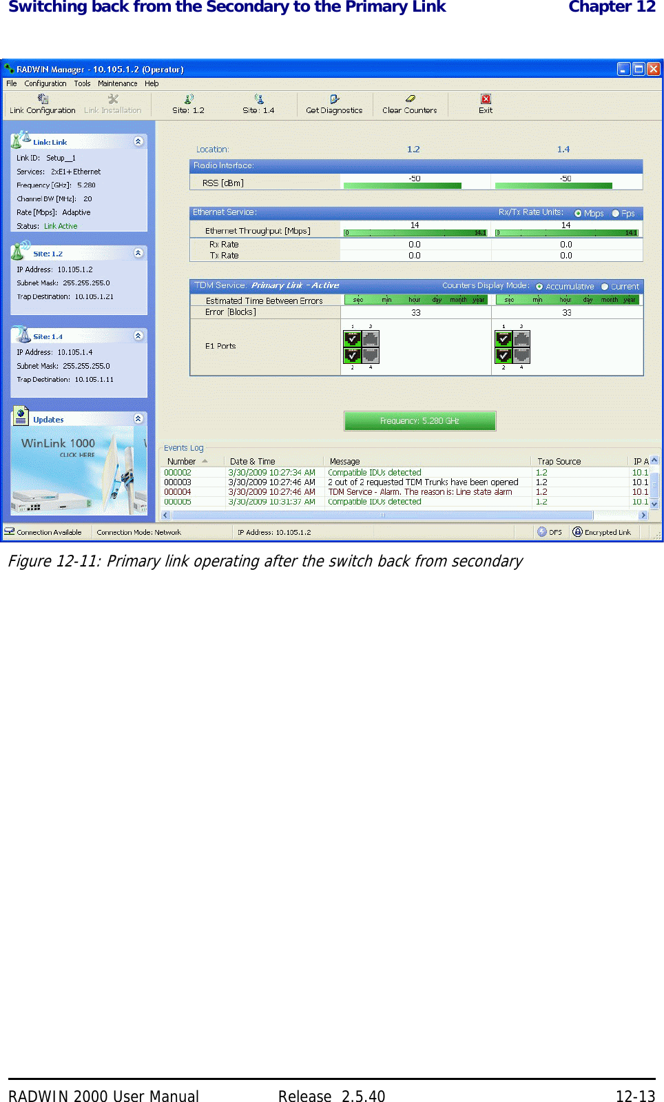
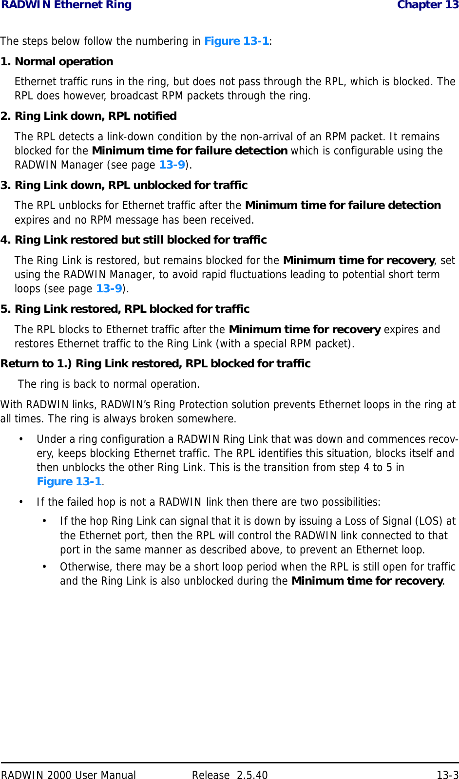
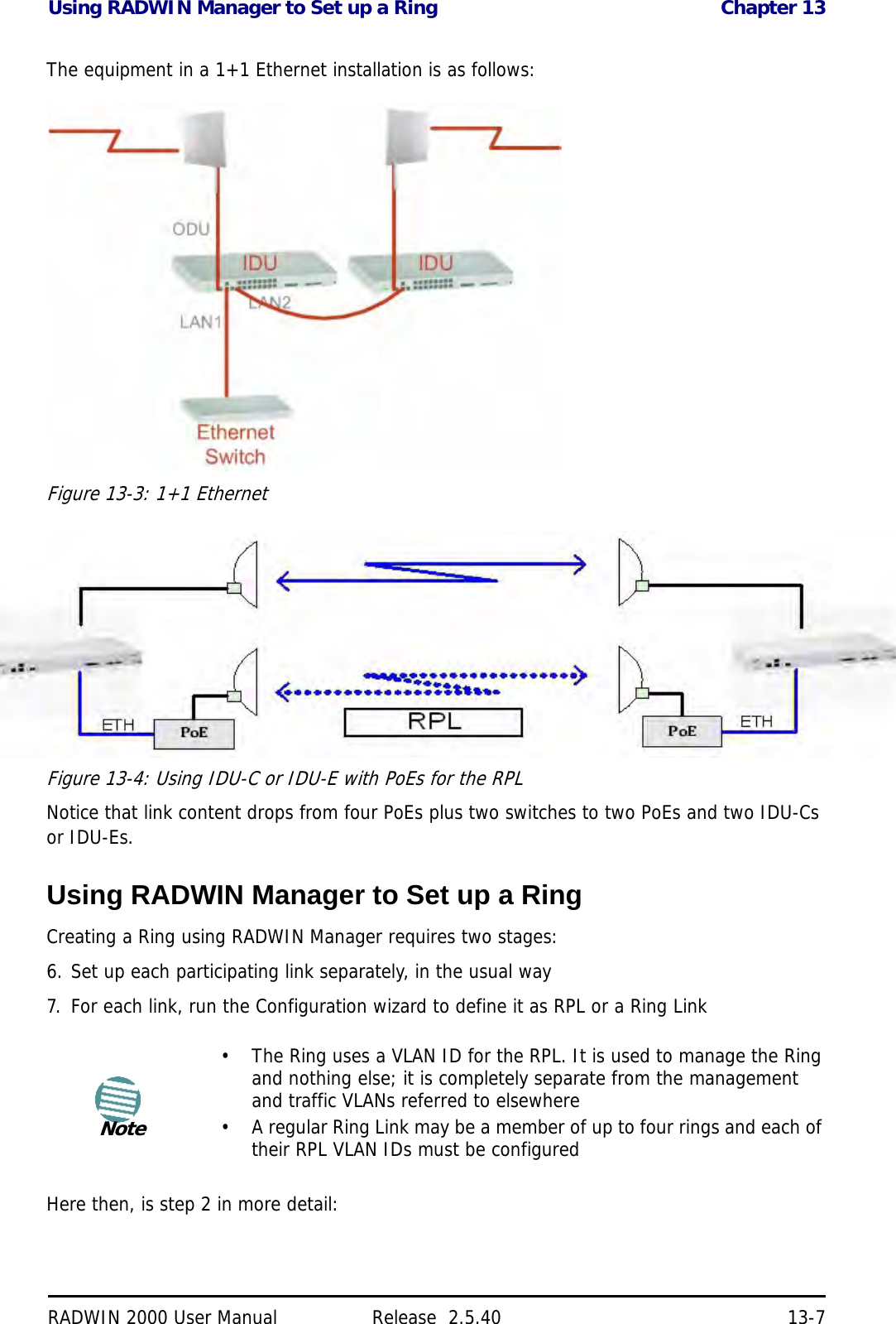
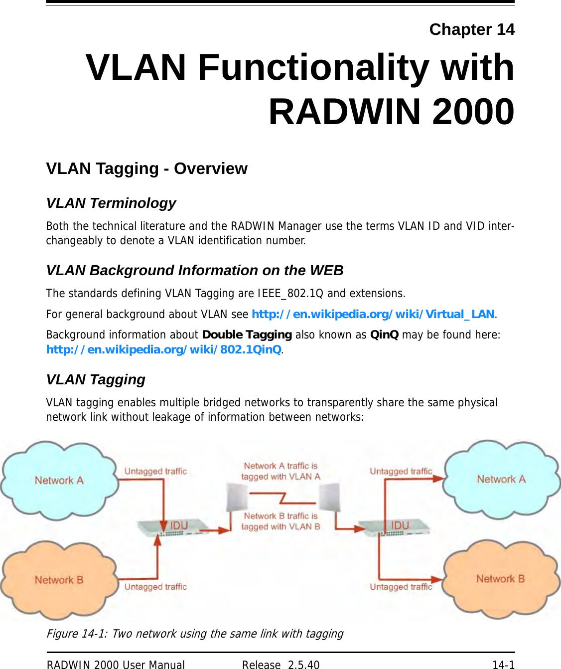
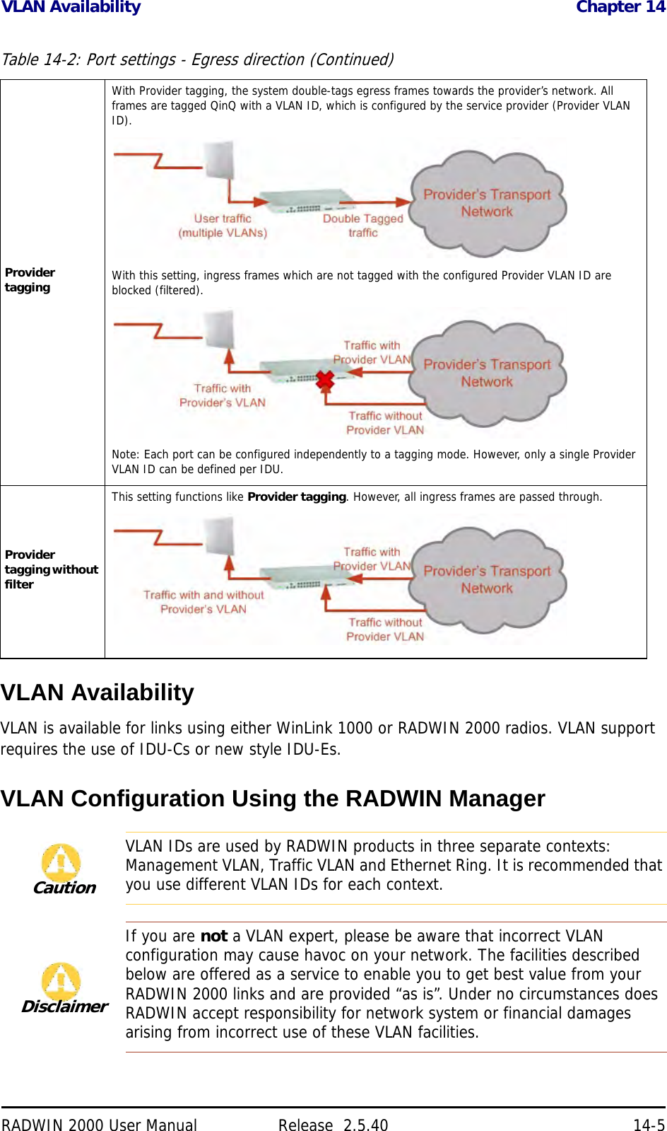
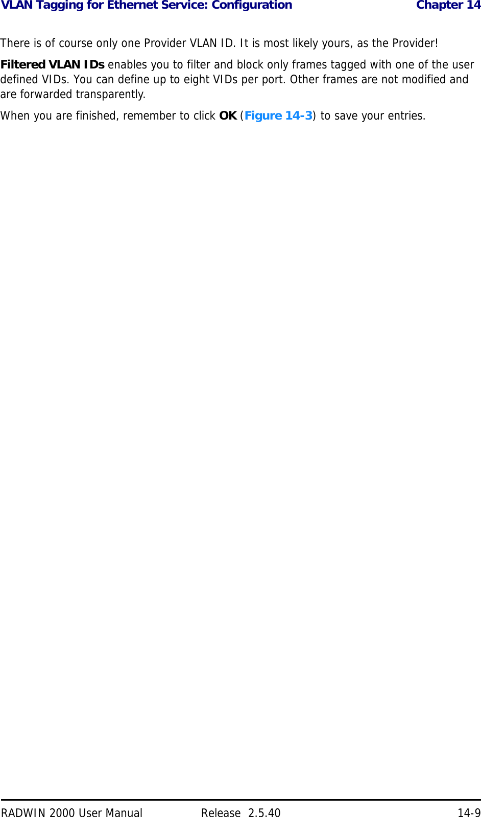
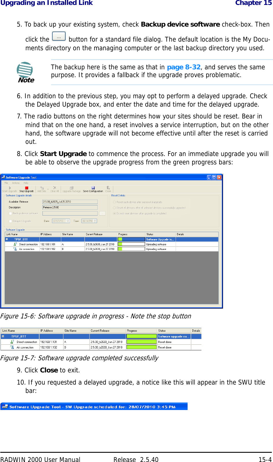
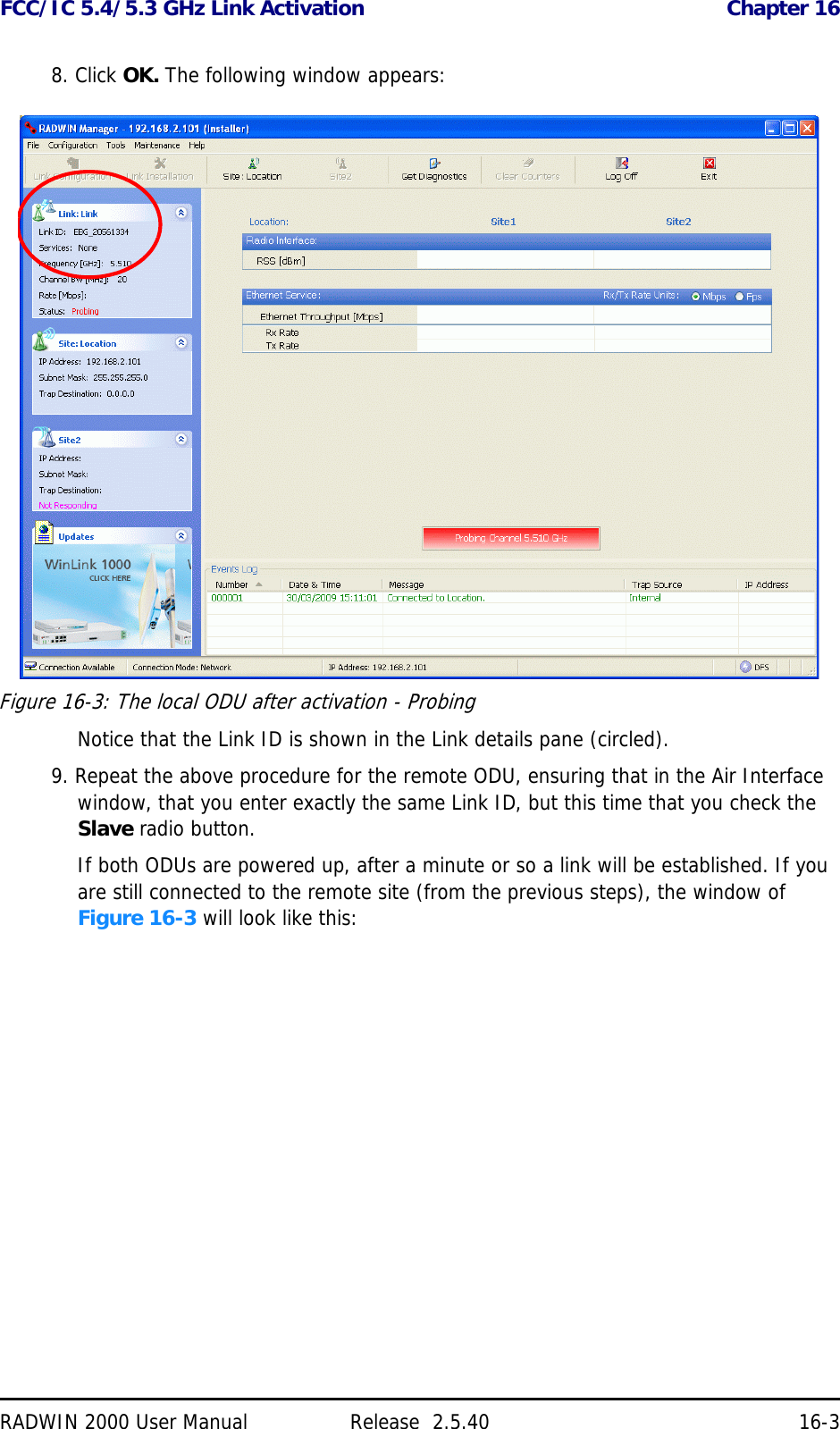
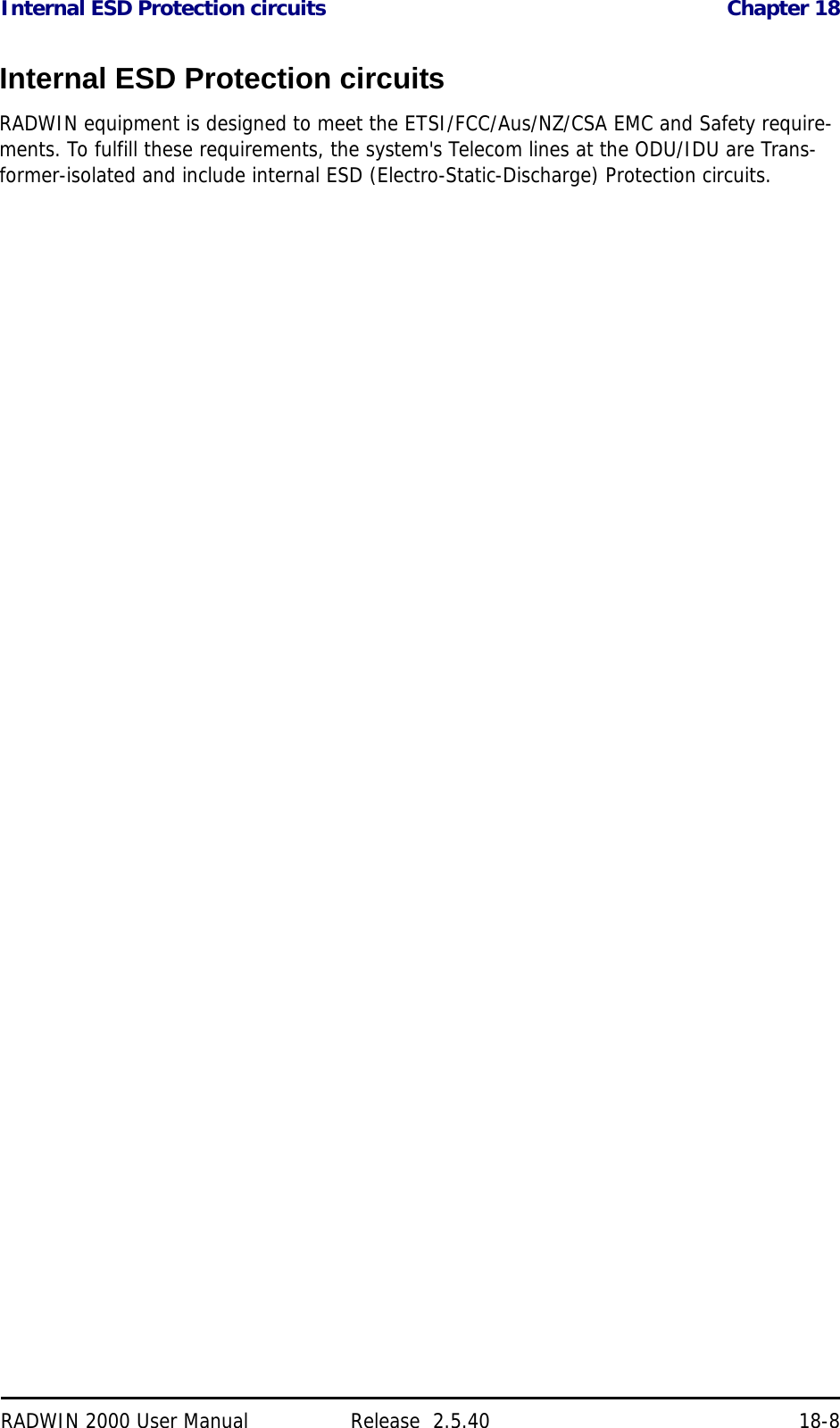
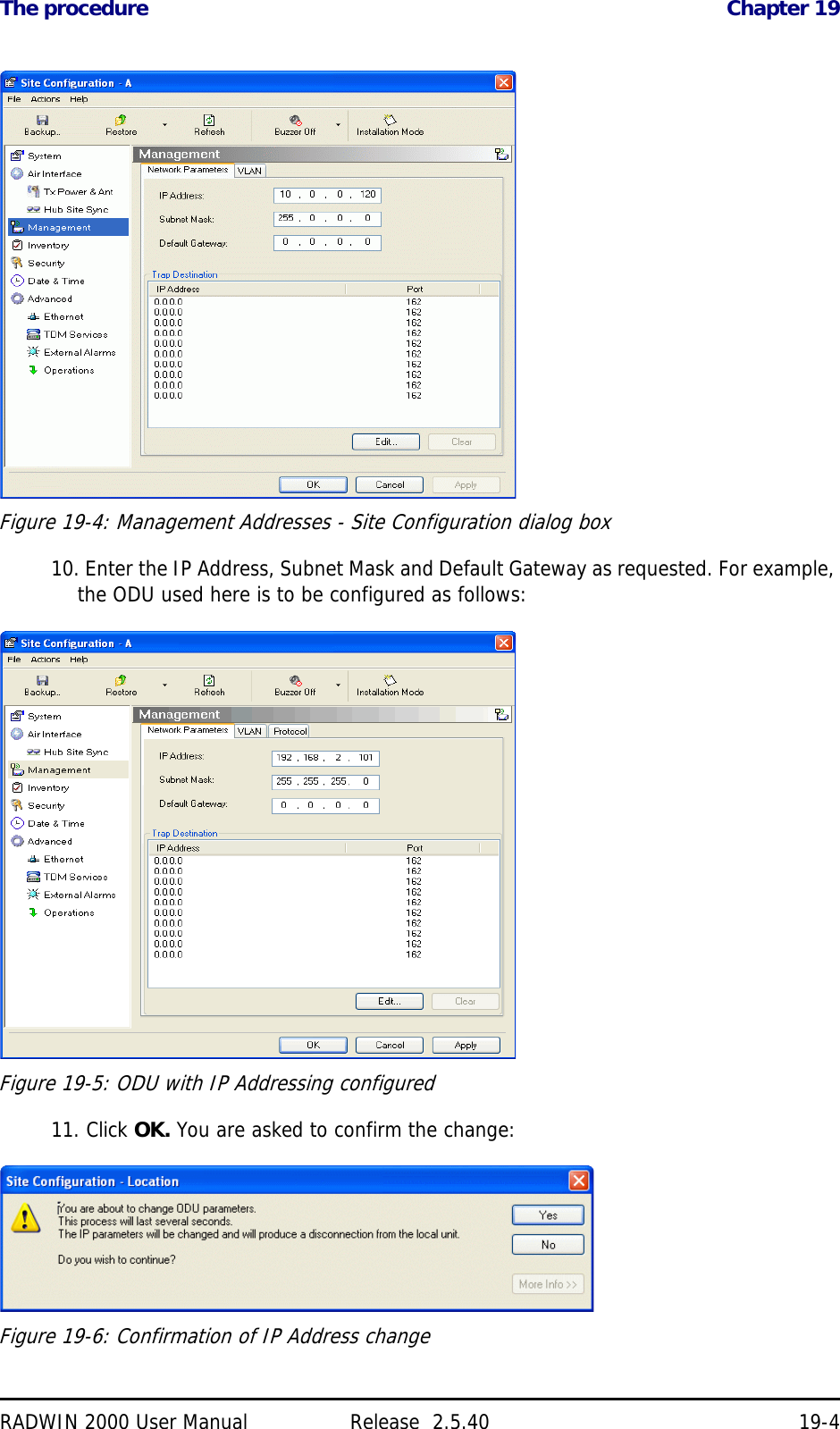
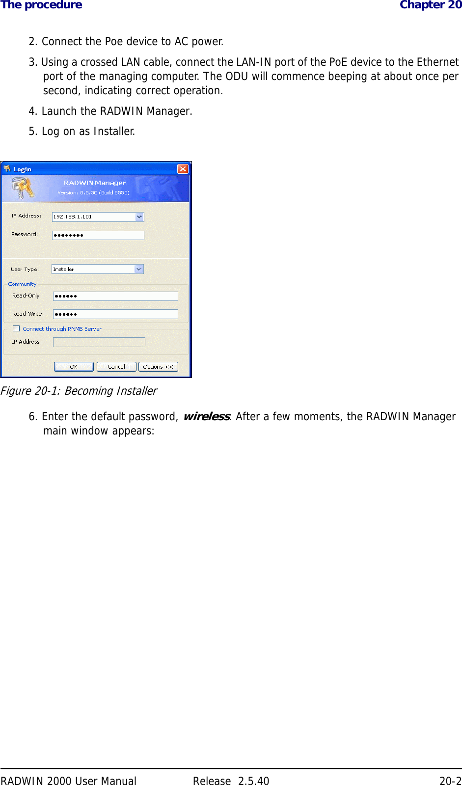
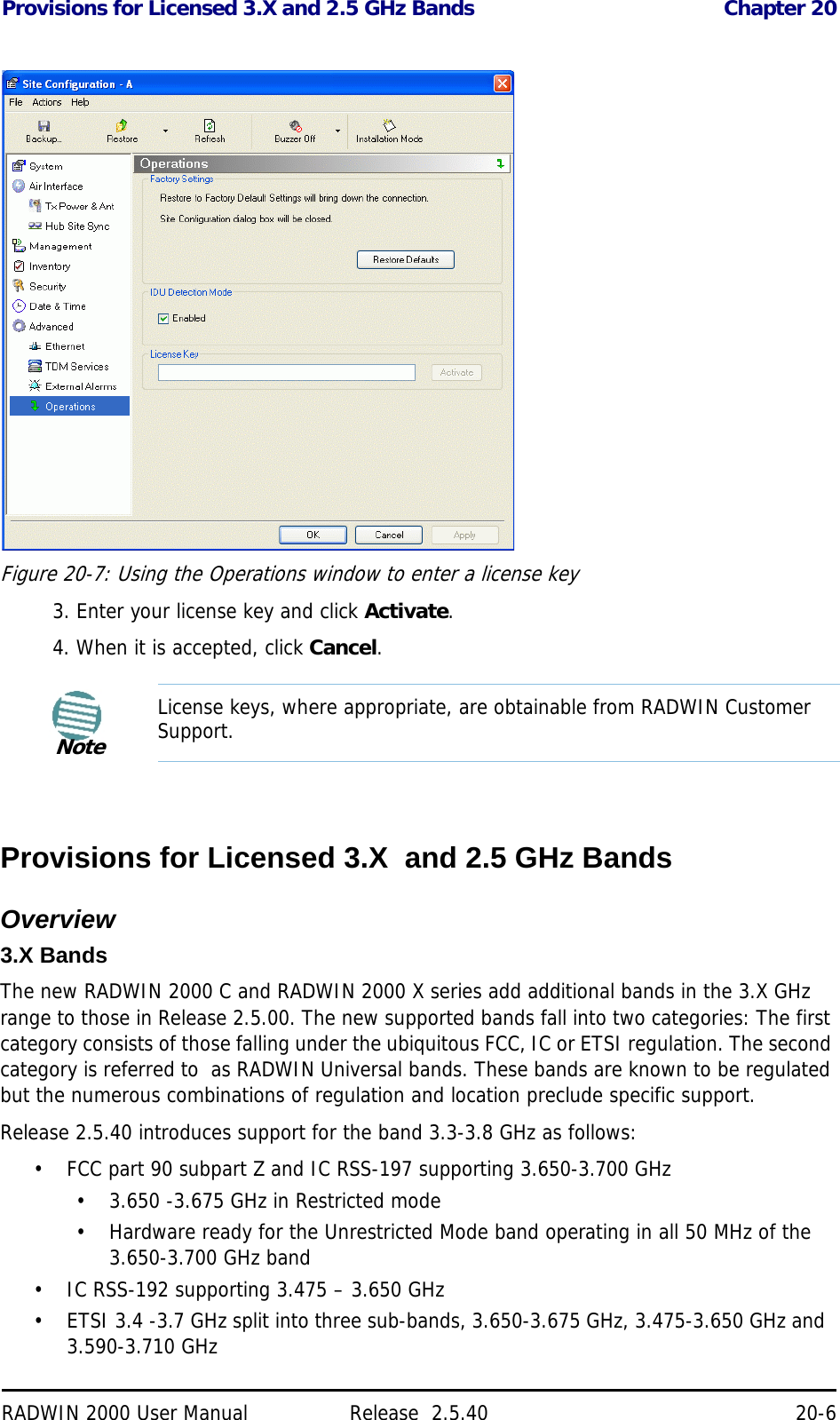
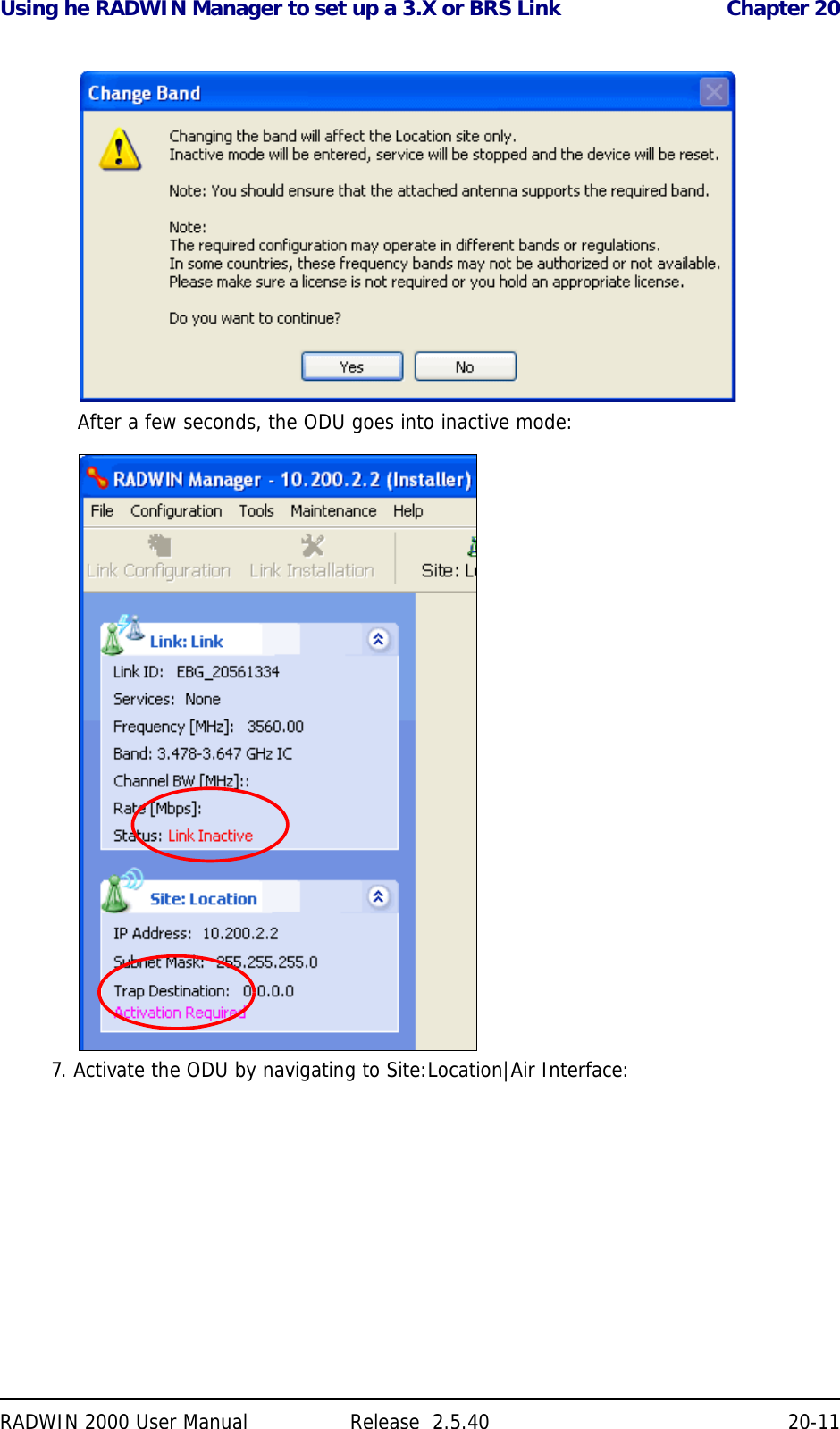
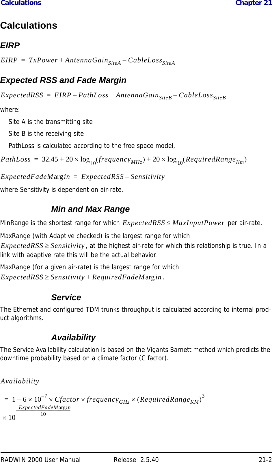
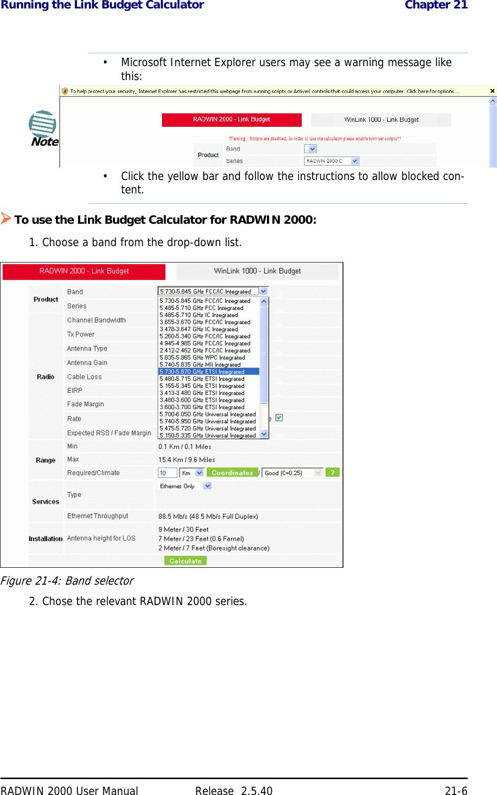
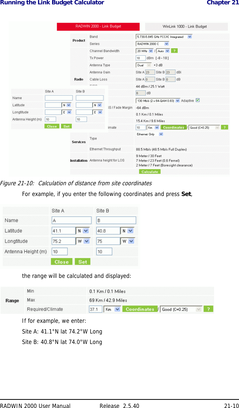
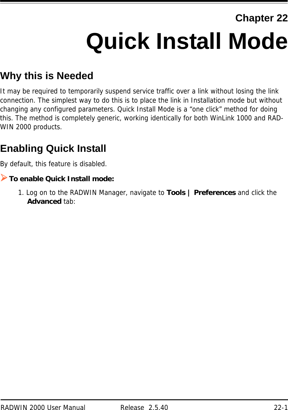
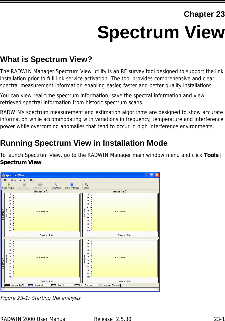
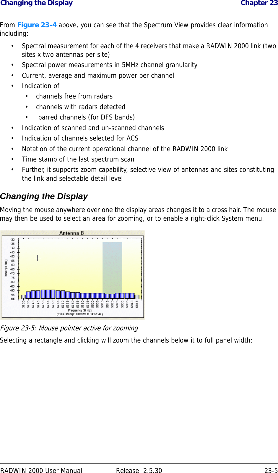
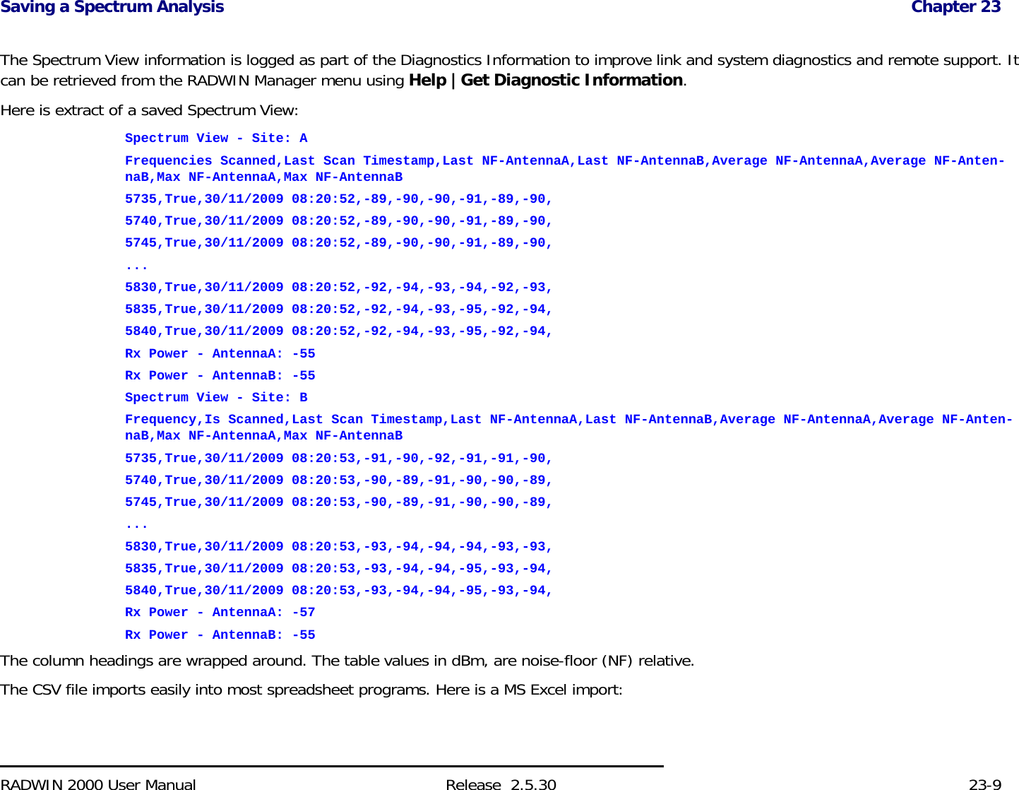
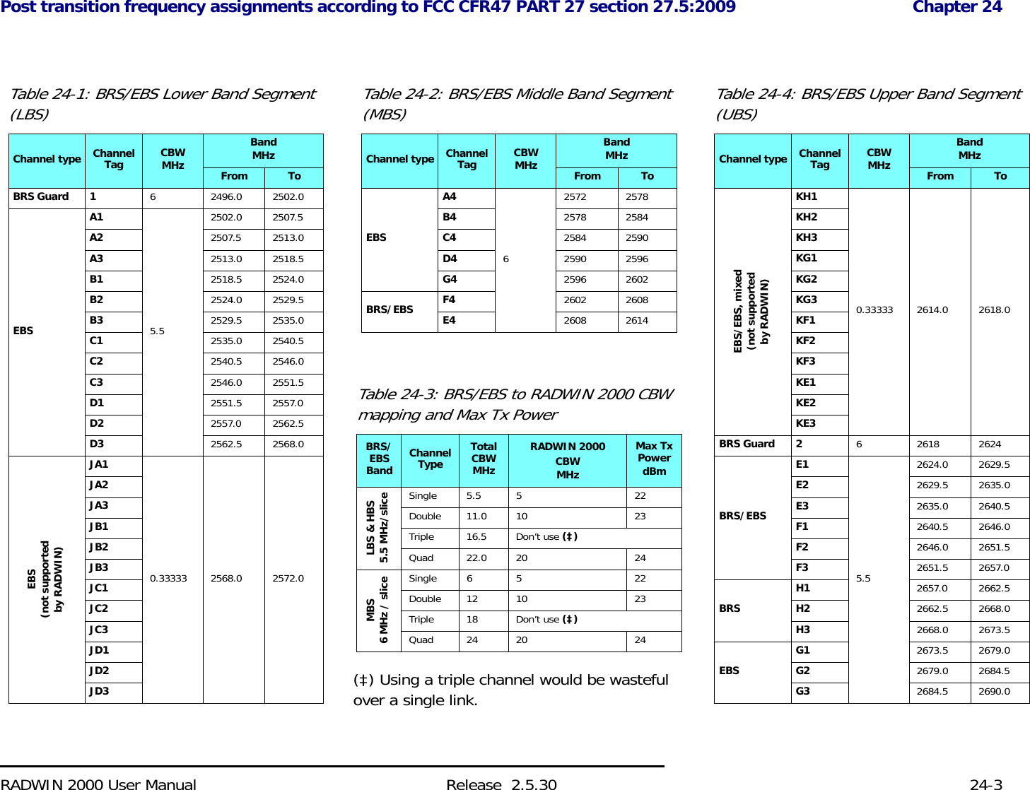
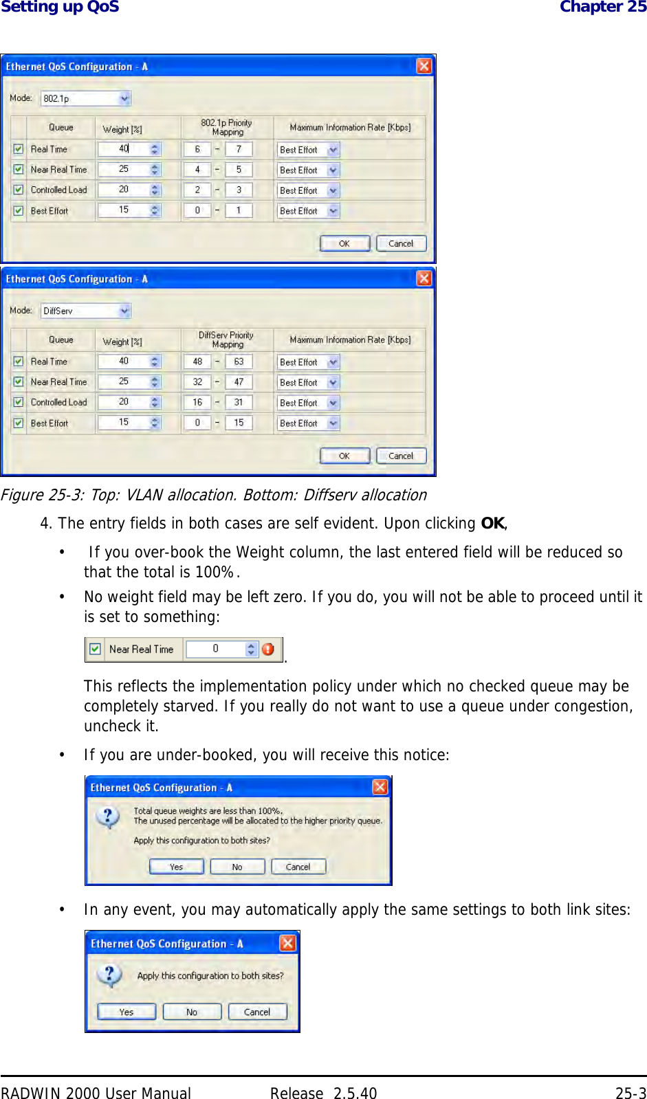
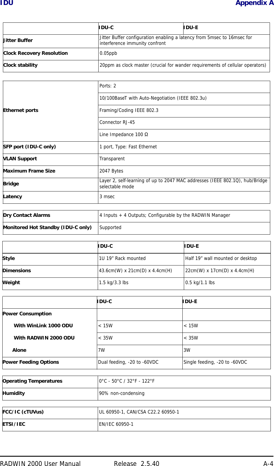
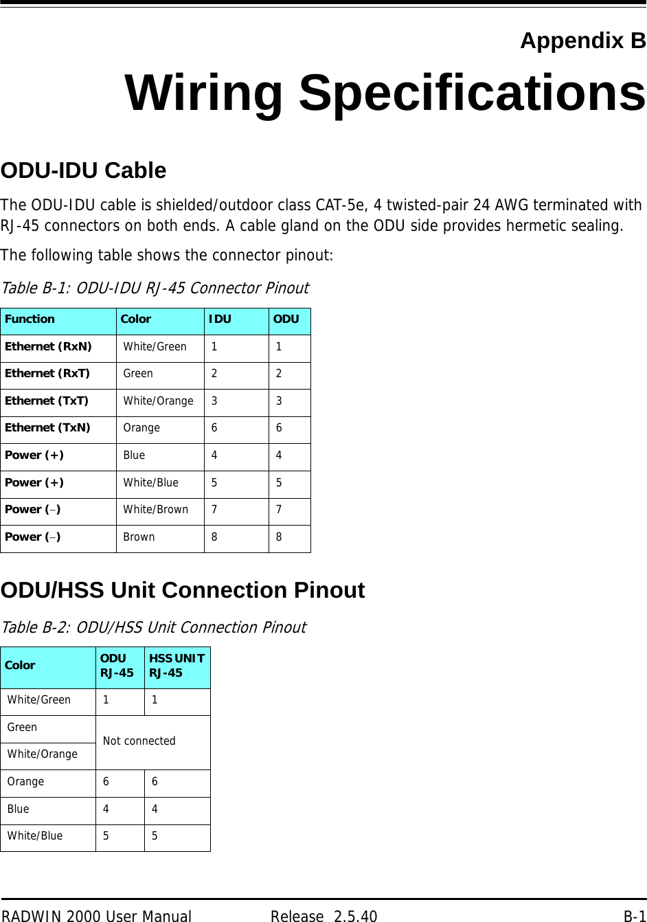
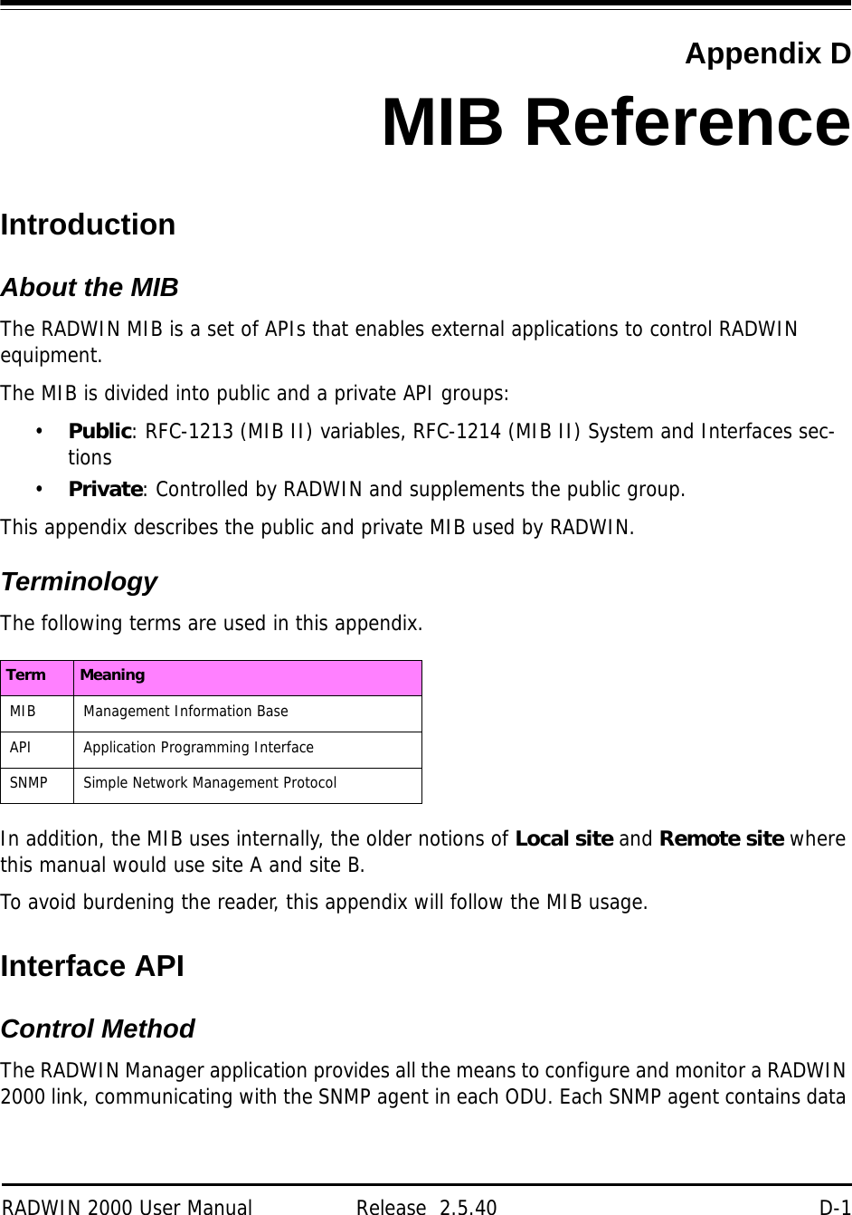
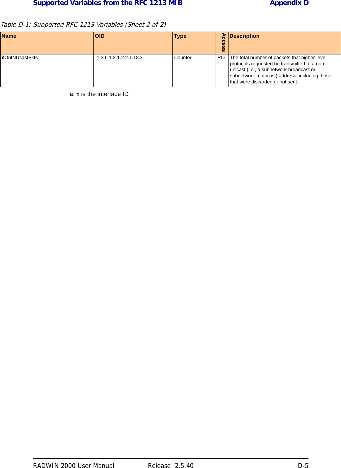
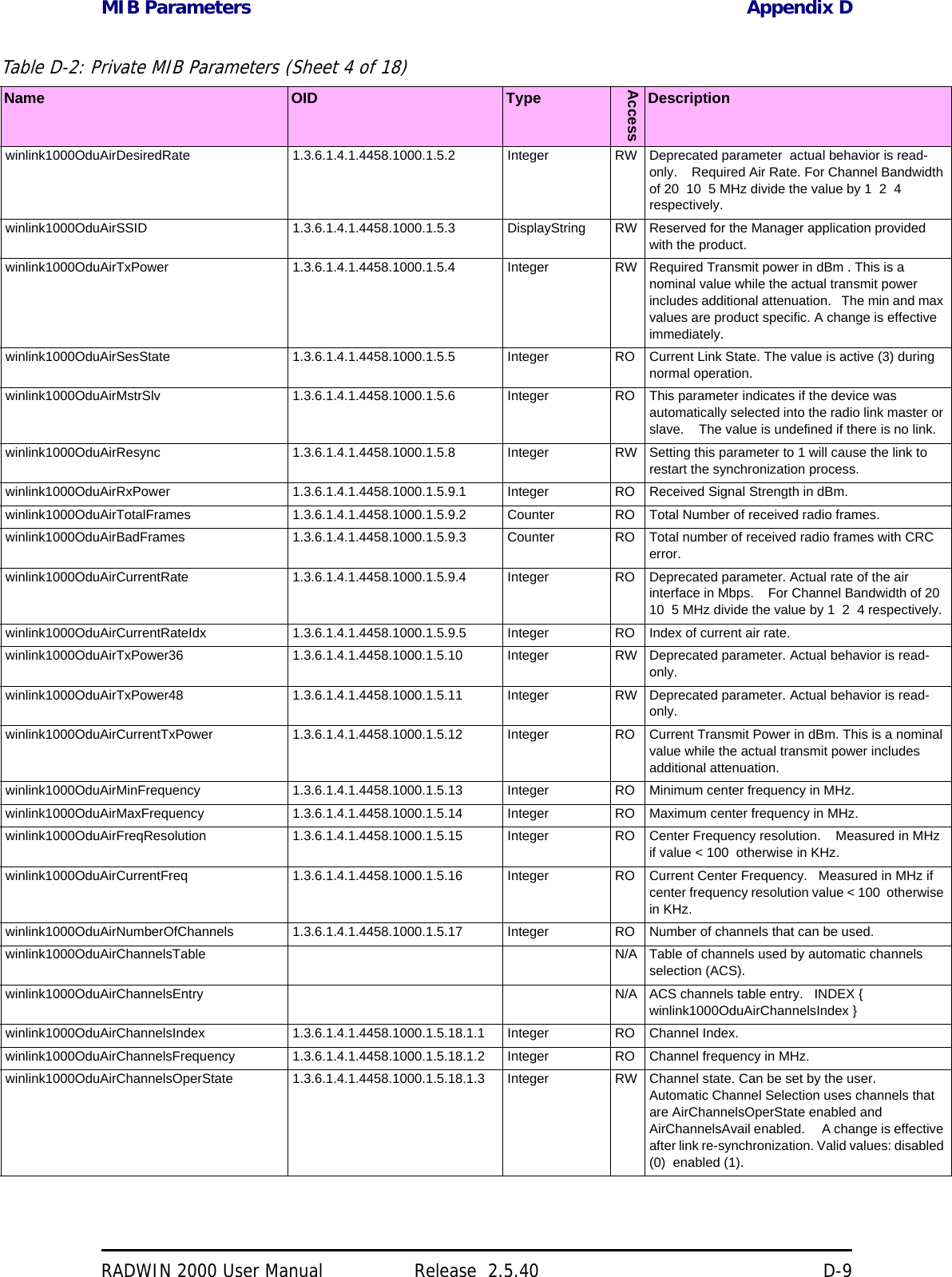
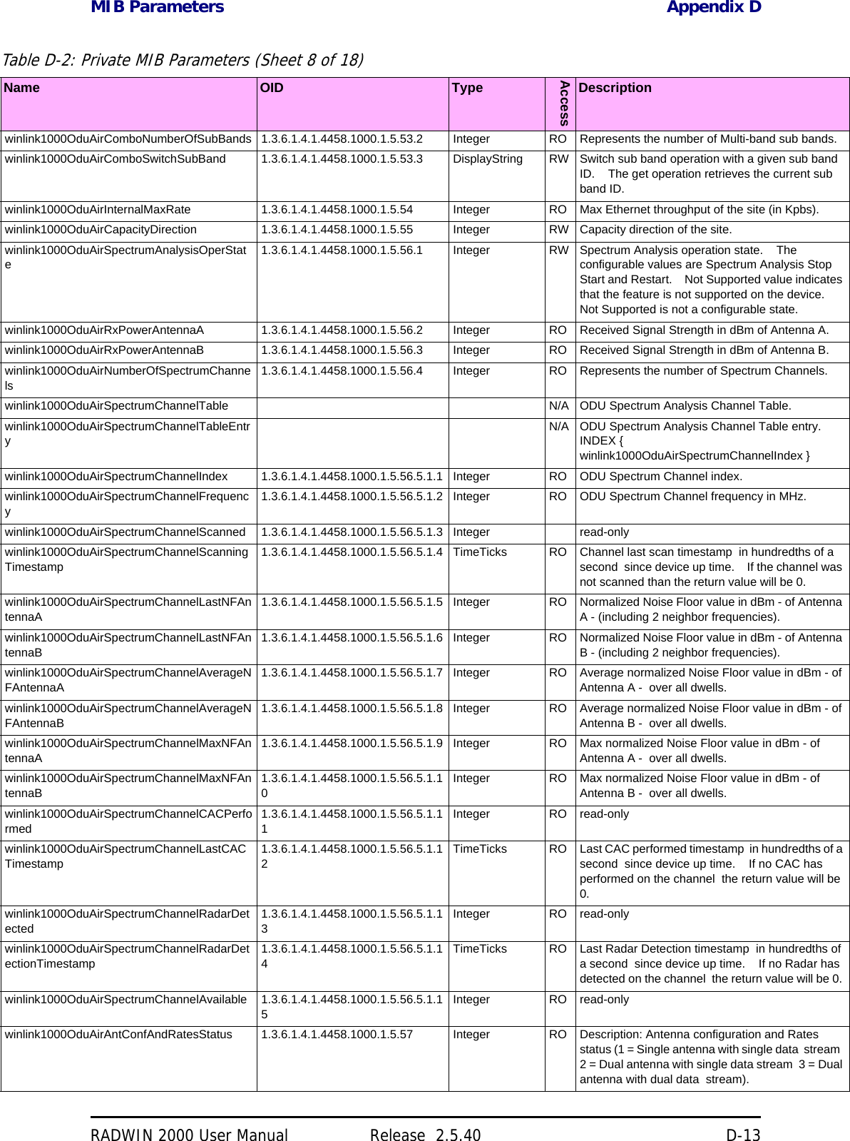
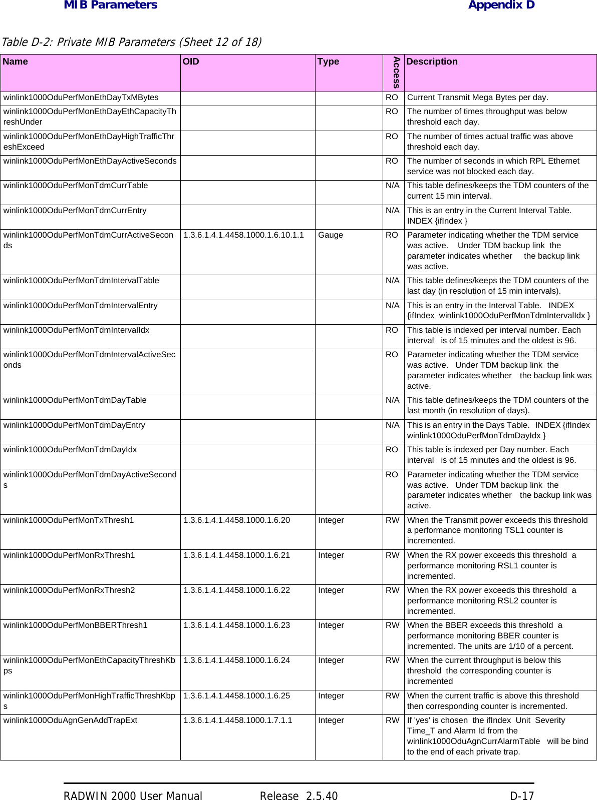
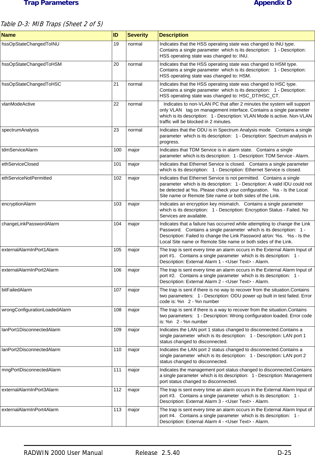
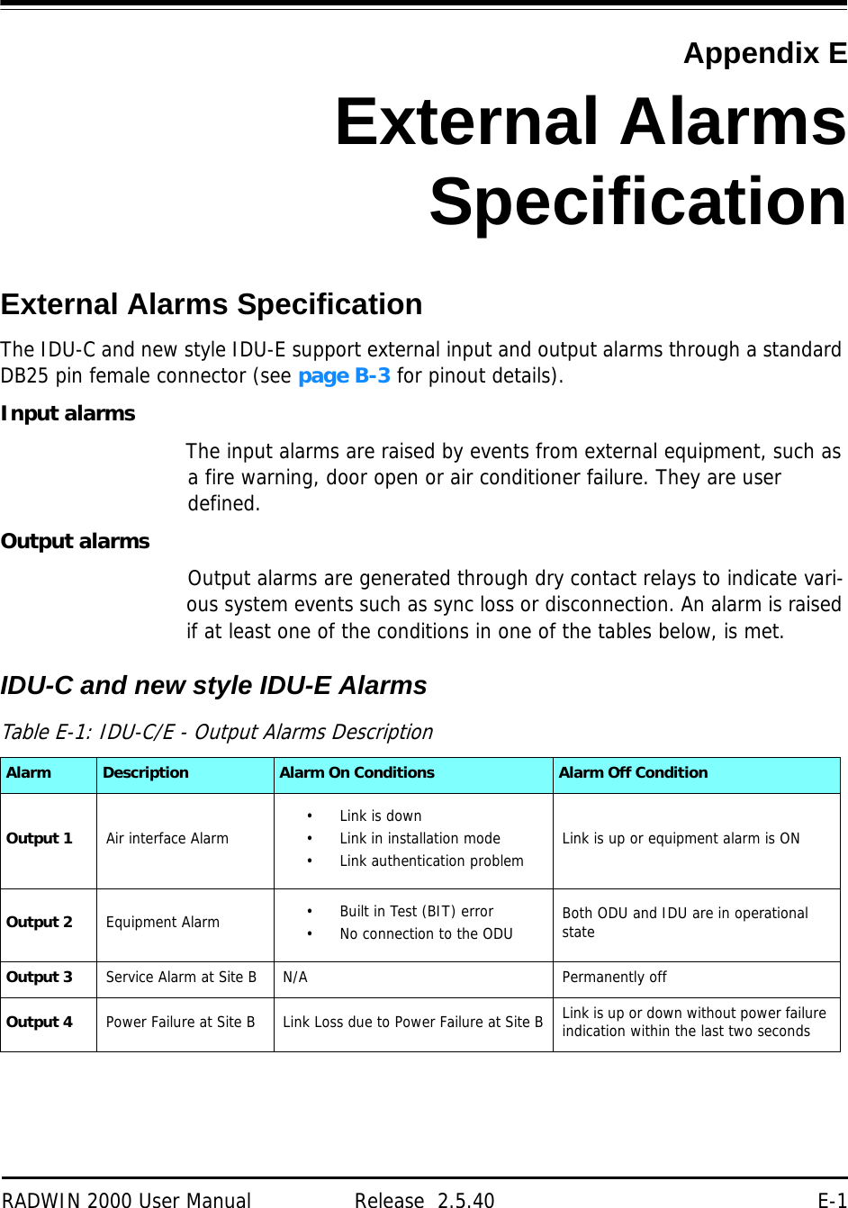
![ODU Appendix ARADWIN 2000 User Manual Release 2.5.40 A-2(‡)Not available for X series ODUs.(†)Split into three sub-bands. See page 20-9.(*) Split into many sub-bands. There are also Tx Power limitations. See Chapter 24, and in particular, tables 24-1 to 24-4.Sensitivity (dBm) @BER <10e-11 (20MHz) -88 -86 -83 -81 -77 -72 -70 -67Encryption AES 128Band Occupied Frequency range [GHz] Compliance Channel Bandwidth5 MHz 10 MHz 20 MHz 40 MHzFCC/IC 5.8 5.725 - 5.850 FCC 47CFR, Part 15, Subpart C and IC RSS-210 No Yes Yes YesFCC 5.4 5.480 - 5.715 FCC 47CFR, Part 15, Subpart E No Yes Yes YesIC 5.4 5.480 – 5.5905.660 – 5.715 IC RSS-210 No Yes Yes YesFCC/IC 5.3 5.260 - 5.340 FCC 47CFR, Part 15, Subpart E and IC RSS-210 No Yes Yes YesFCC/IC 4.9 4.940 - 4.990 FCC 47CFR, Part 90, Subpart Y and IC RSS-111 No Yes Yes NoFCC/IC 2.4 2.402 - 2.472 FCC 47CFR, Part 15, Subpart C and IC RSS-210 No Yes Yes NoFCC/IC 3.6(Lic) 3.650 - 3.675 FCC Part 90 Subpart Z and IC RSS-197 (Restricted) Yes Yes(‡) Yes(‡) NoFCC 2.5(*) 2.495 2.690 FCC CFR47 PART 27 section 27.5:2009 (BRS/EBS) Yes Yes Yes NoIC 3.4 (Lic) 3.475 – 3.650 IC RSS-192 Yes Yes(‡) Yes(‡) NoWPC India 5.8 5.825 – 5.875 GSR-38 No Yes Yes YesMII China 5.8 5.730 – 5.845 MII China No Yes Yes YesETSI 5.8 5.735 – 5.865 ETSI EN 302 502 No Yes Yes NoETSI 5.4 5.480 – 5.715 ETSI EN 301 893 No Yes Yes YesETSI 5.3 5.160 – 5.340 ETSI EN 301 893 No Yes Yes NoETSI 3.4 (Lic)(†) 3.400 - 3.700 ETSI EN 302 326-2 Yes Yes(‡) Yes(‡) NoUniversal 6.0 5.690– 6.060N/ANo Yes Yes YesUniversal 5.9 5.730 – 5.960 No Yes Yes YesUniversal 5.4 5.490 – 5.710 No Yes Yes YesUniversal 5.3 5.140 – 5.345 No Yes Yes YesUniversal 4.9 4.890 - 5.010 No Yes Yes YesUniversal 4.8 4.800 - 4.900 No Yes Yes YesUniversal 2.3 2.302 - 2.379 No Yes Yes NoUniversal 3.4 3.300 - 3.800 Yes Yes(‡) Yes(‡) NoODU with Integrated Antenna 37.1/14.84(W) x 37.1/14.84(H) x 9.00/3.6(D) cm/in; 3.5 kg / 7 lbsODU Connectorized 18.0/7.2(W) x 27.0/10.8(H) x 5.5/2.2(D) cm/in; 1.5 kg / 3.0 lbsPower Feeding Dual feeding, -20 to -60 VDC (AC/DC converter is available)Power Consumption - alone 25WPower Consumption with IDU See IDU specifications, this Appendix](https://usermanual.wiki/Radwin/RW2025.User-Manual-Part-2/User-Guide-1437359-Page-122.png)
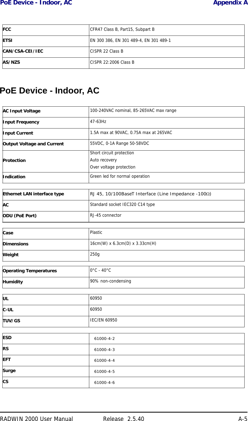
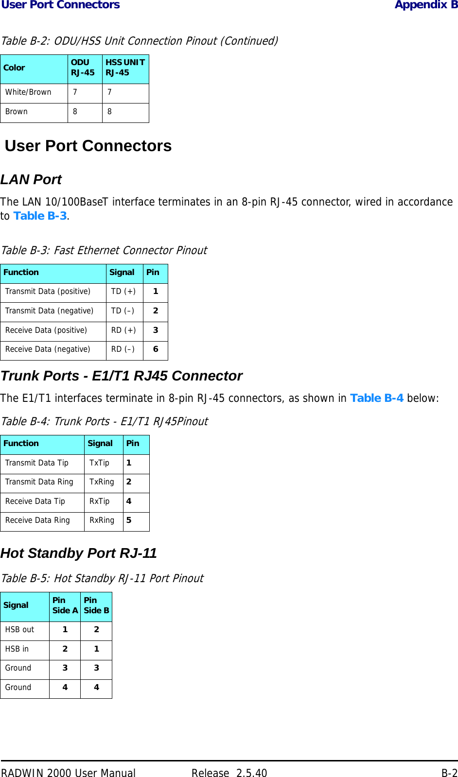


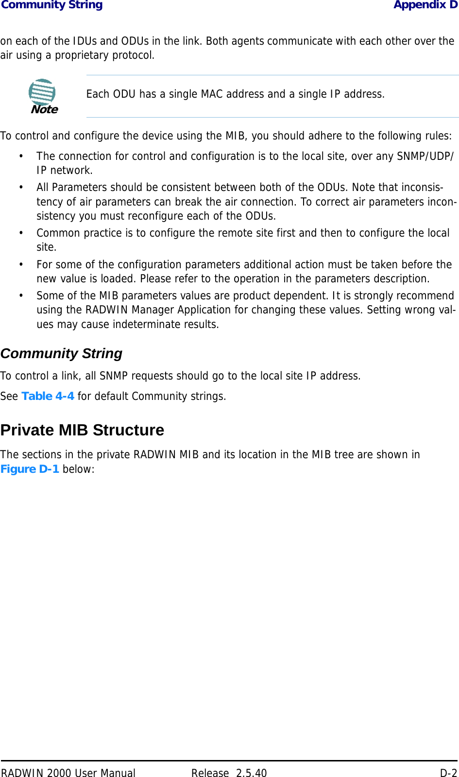
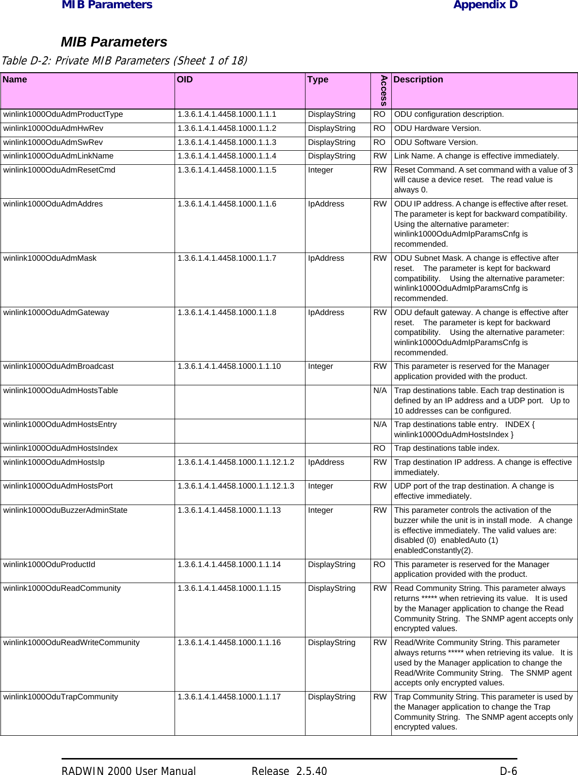
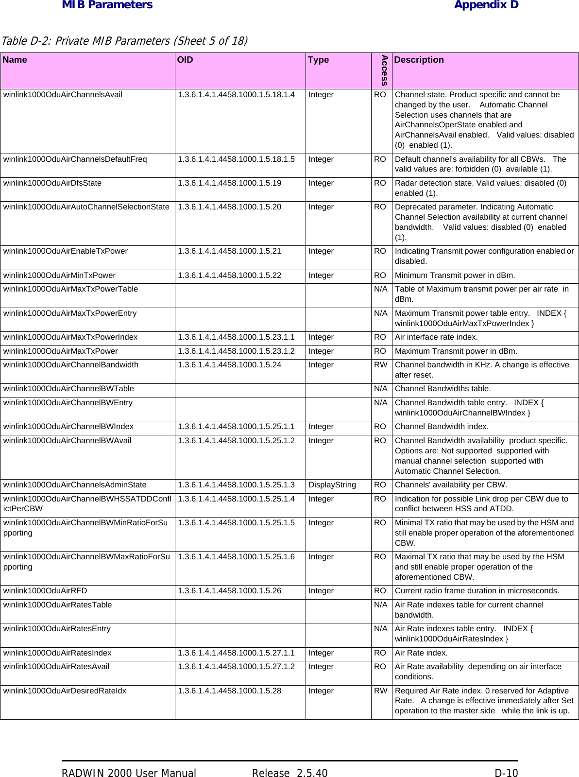
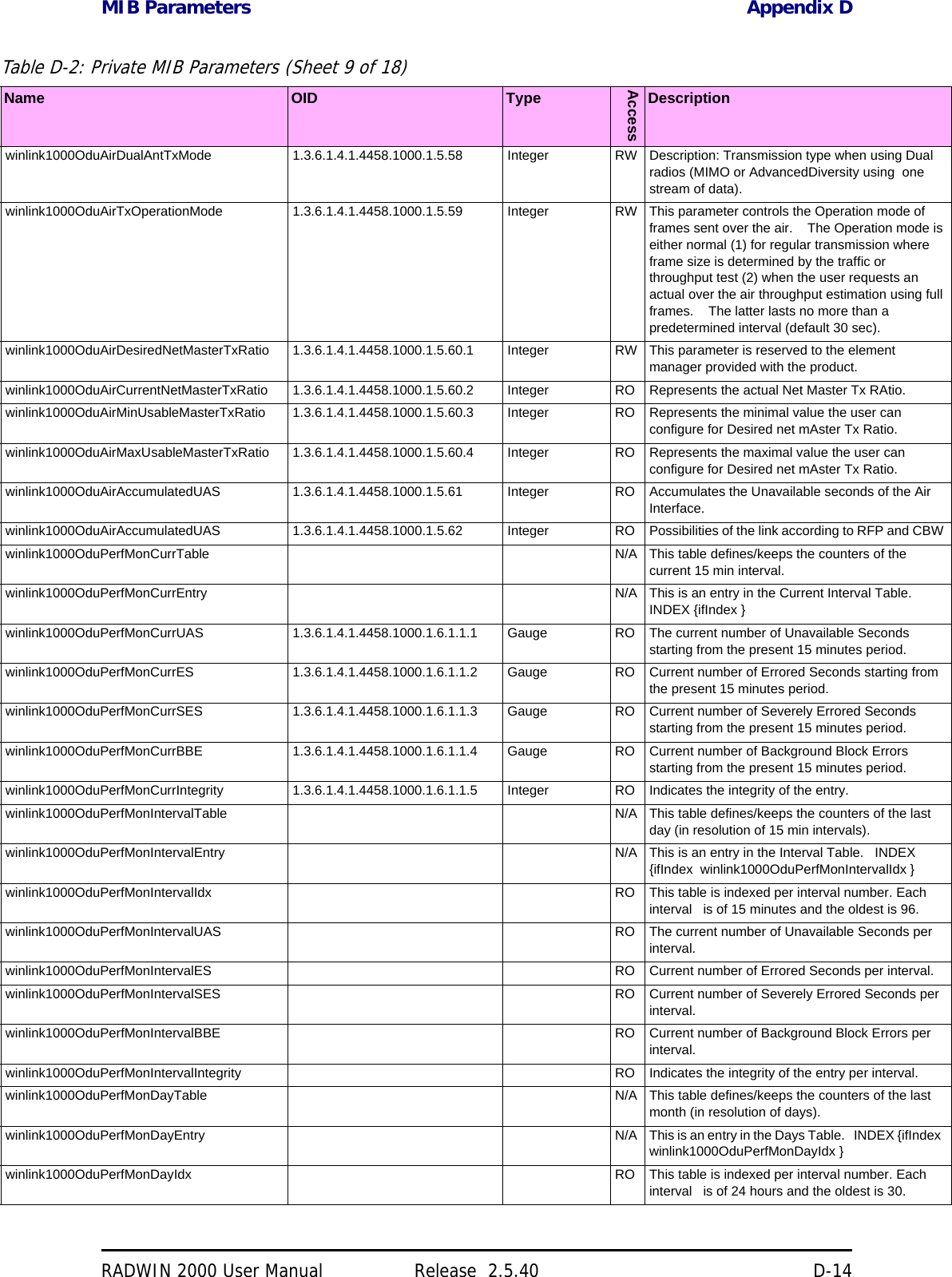
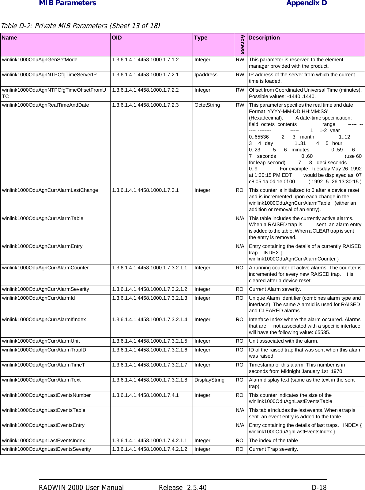
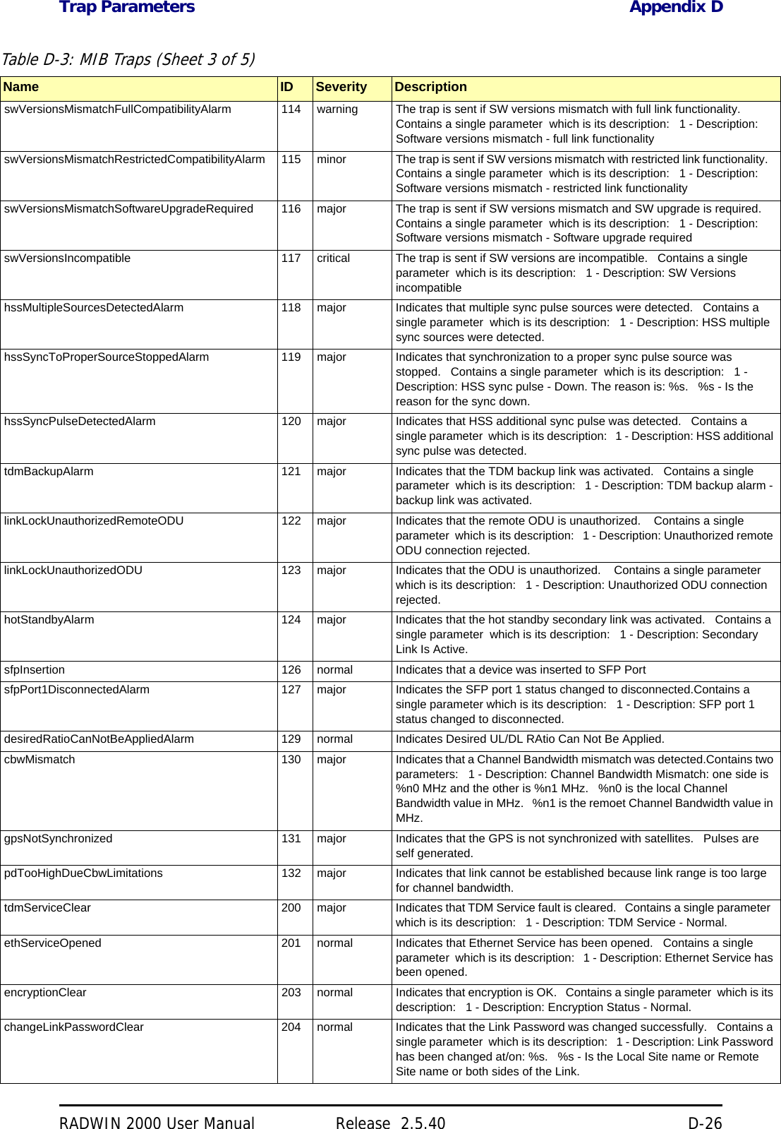
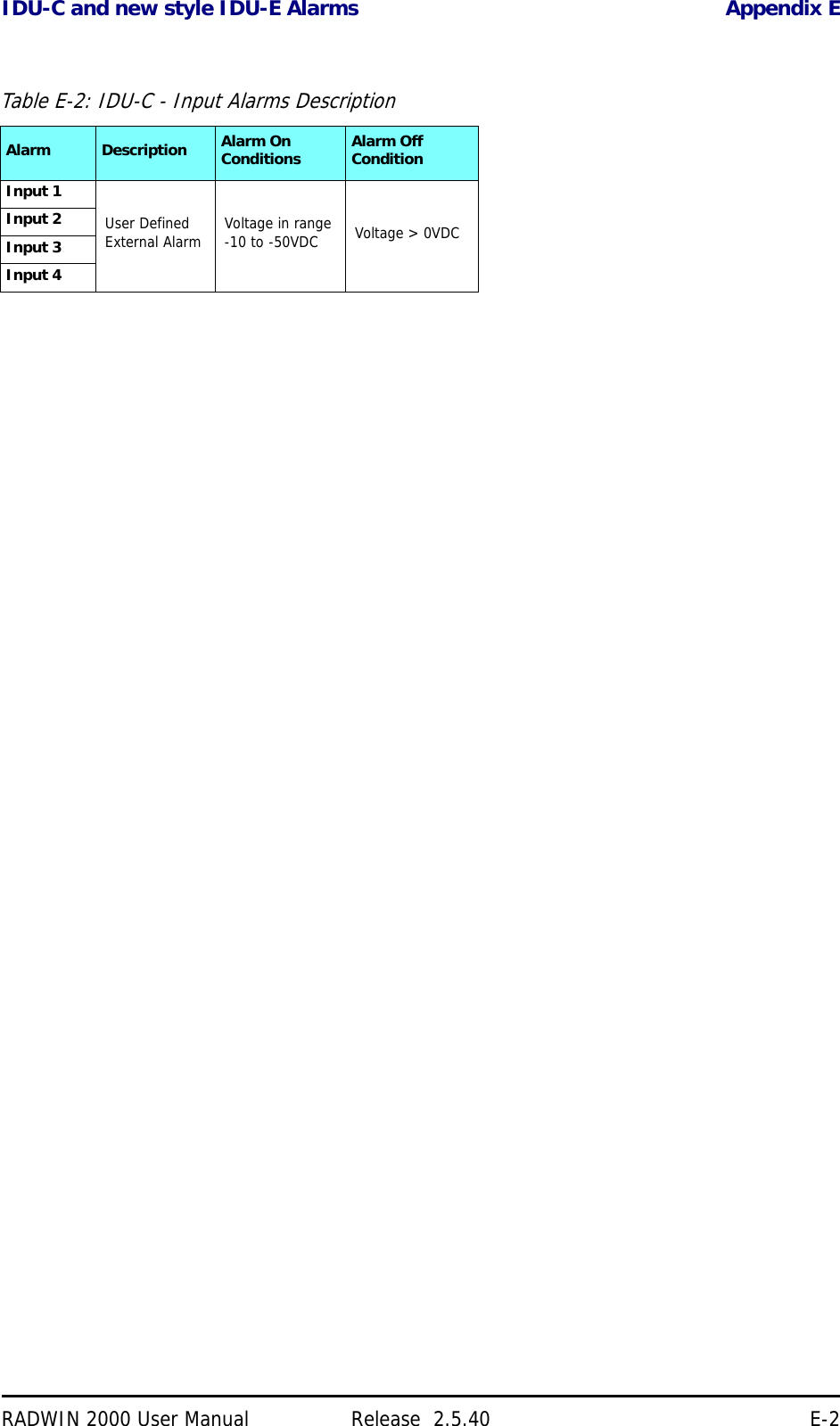
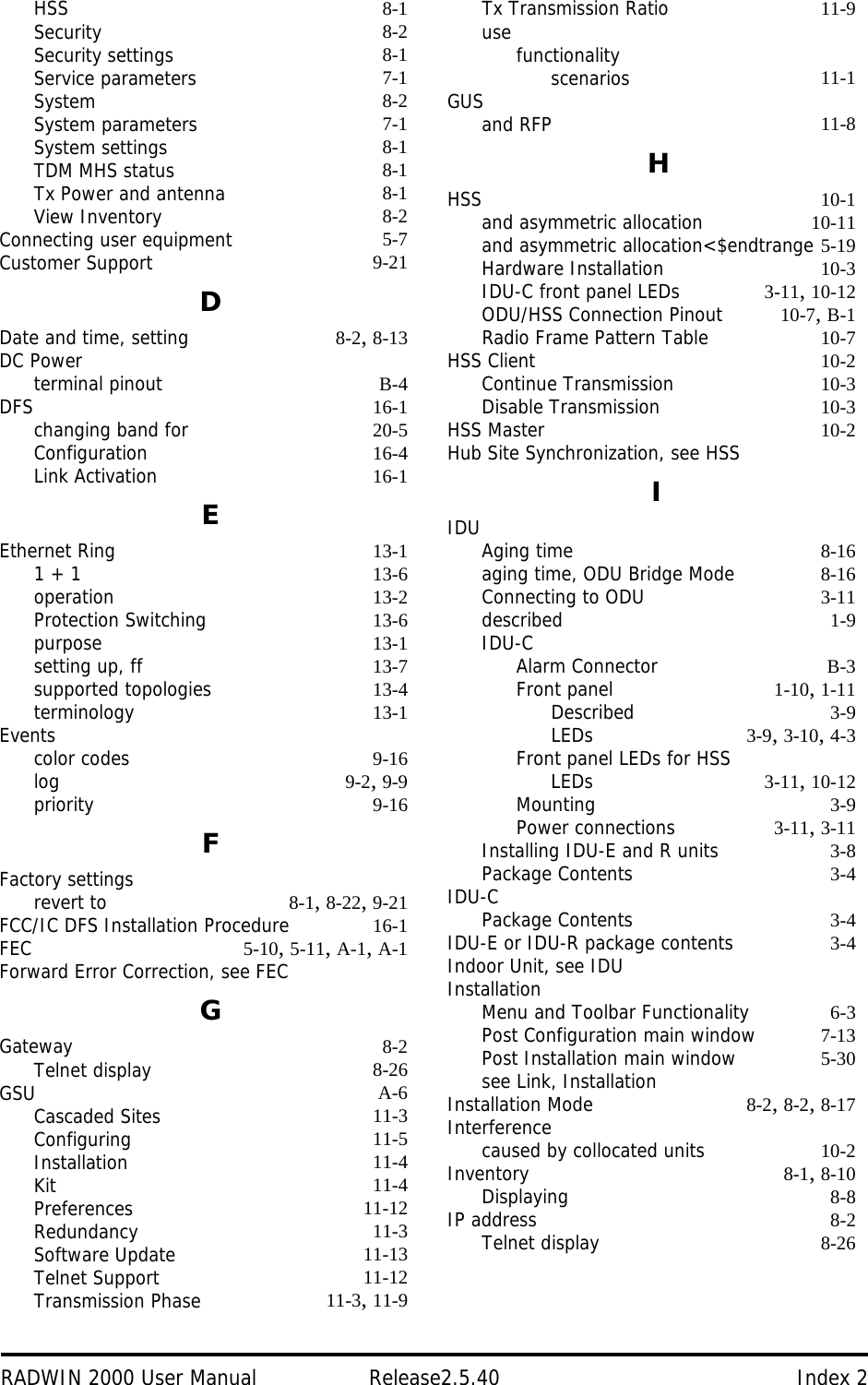
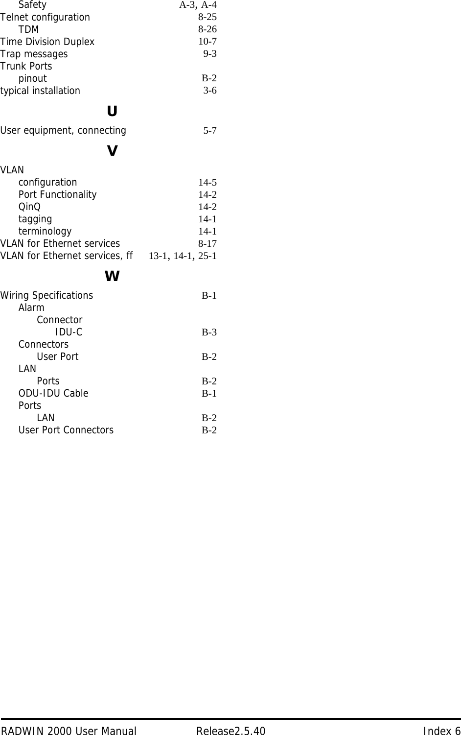
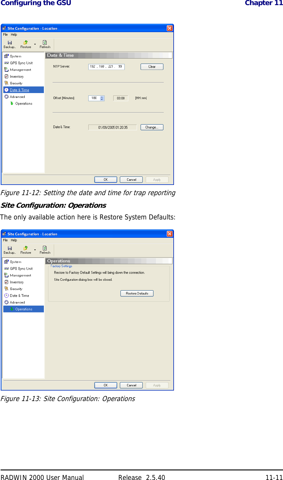
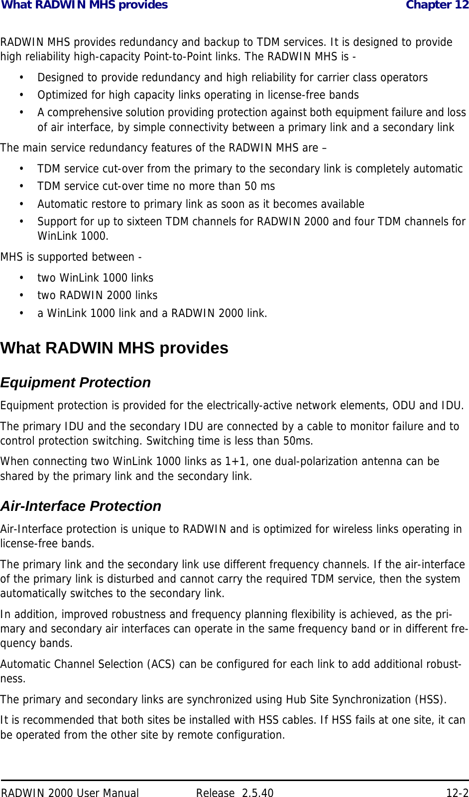
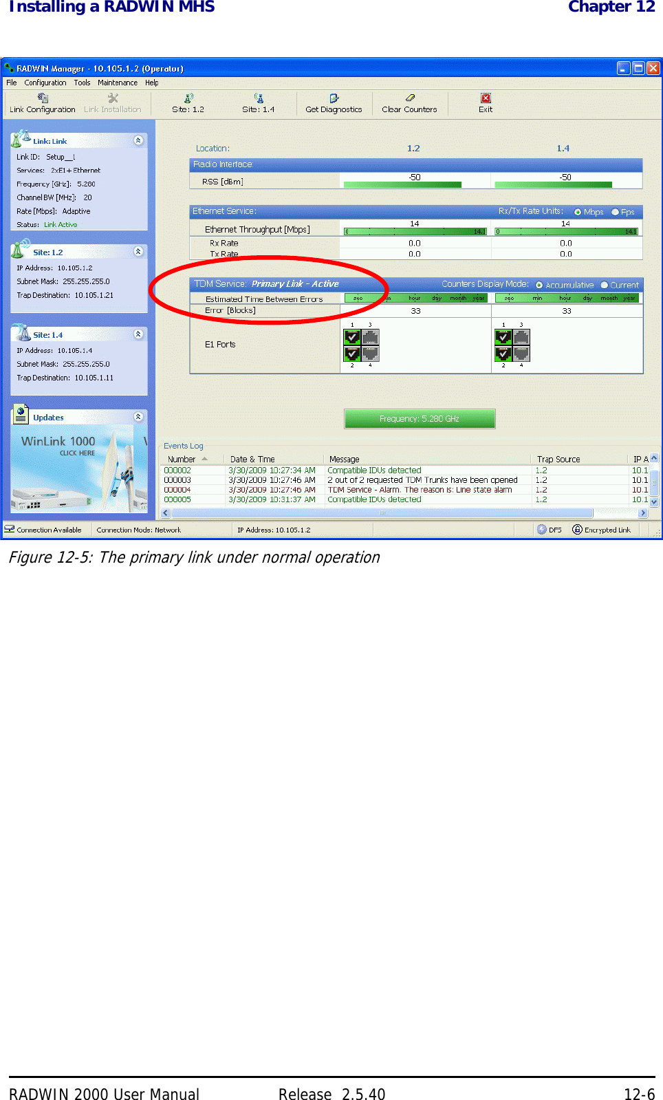
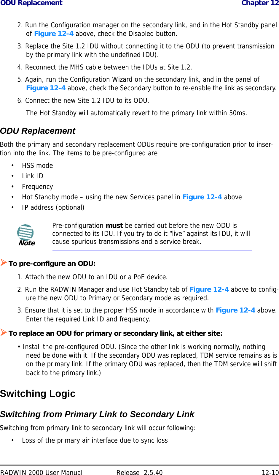
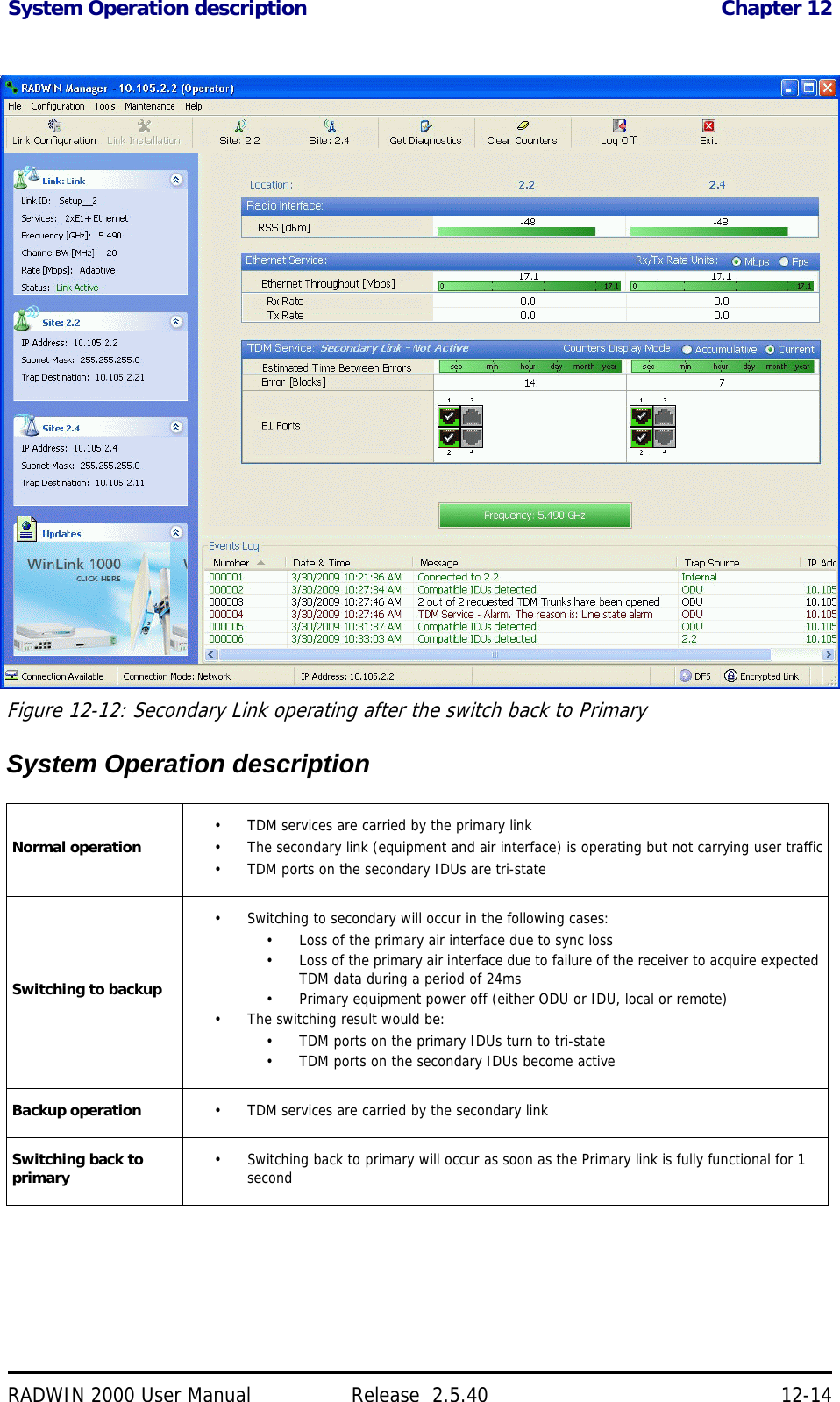
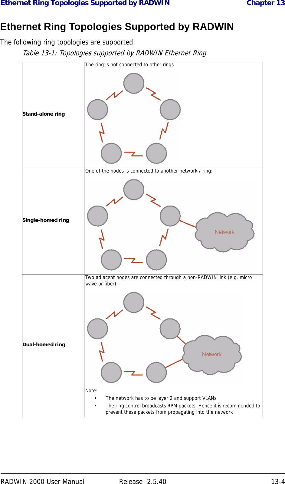
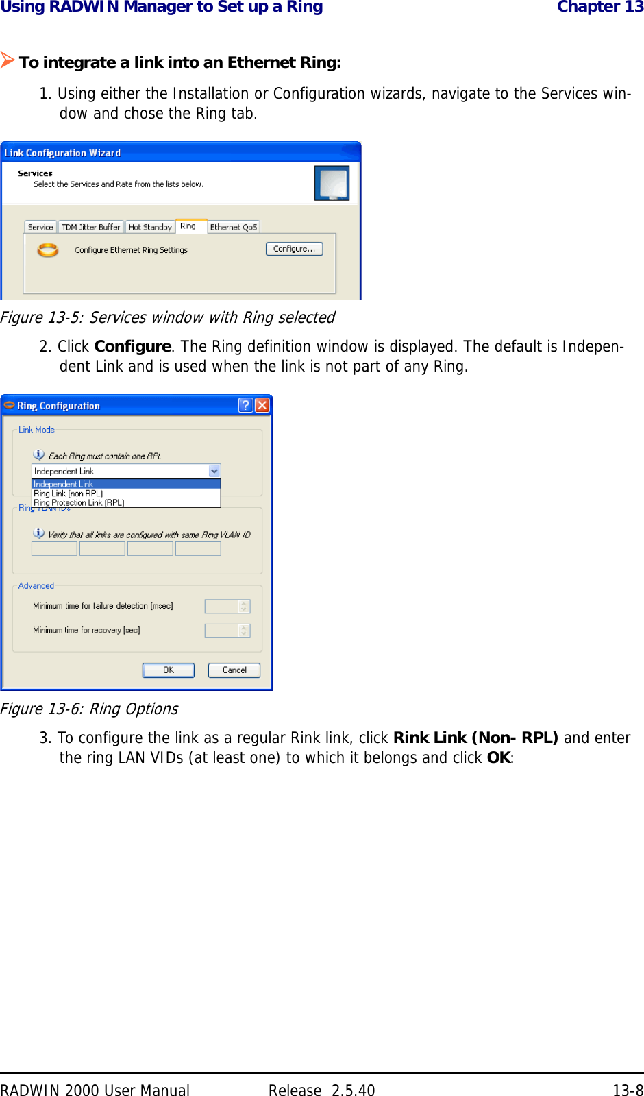
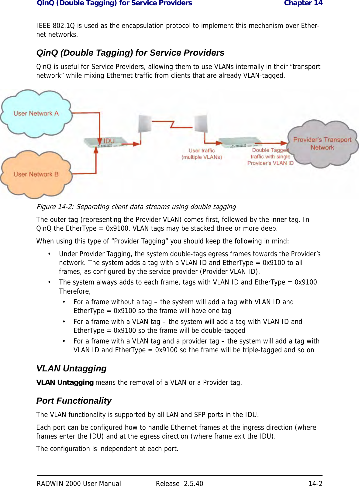
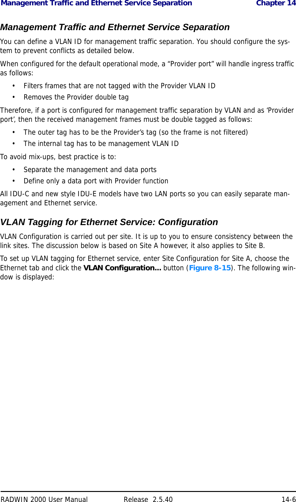
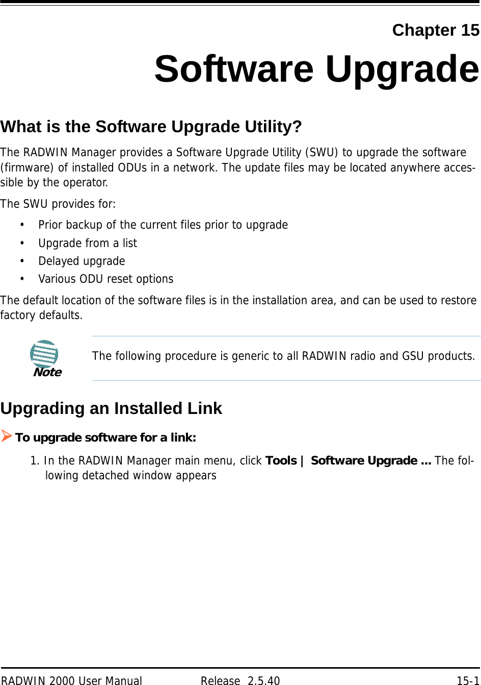
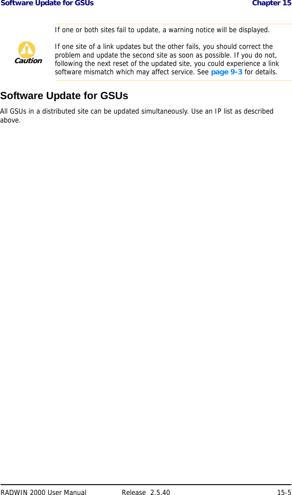
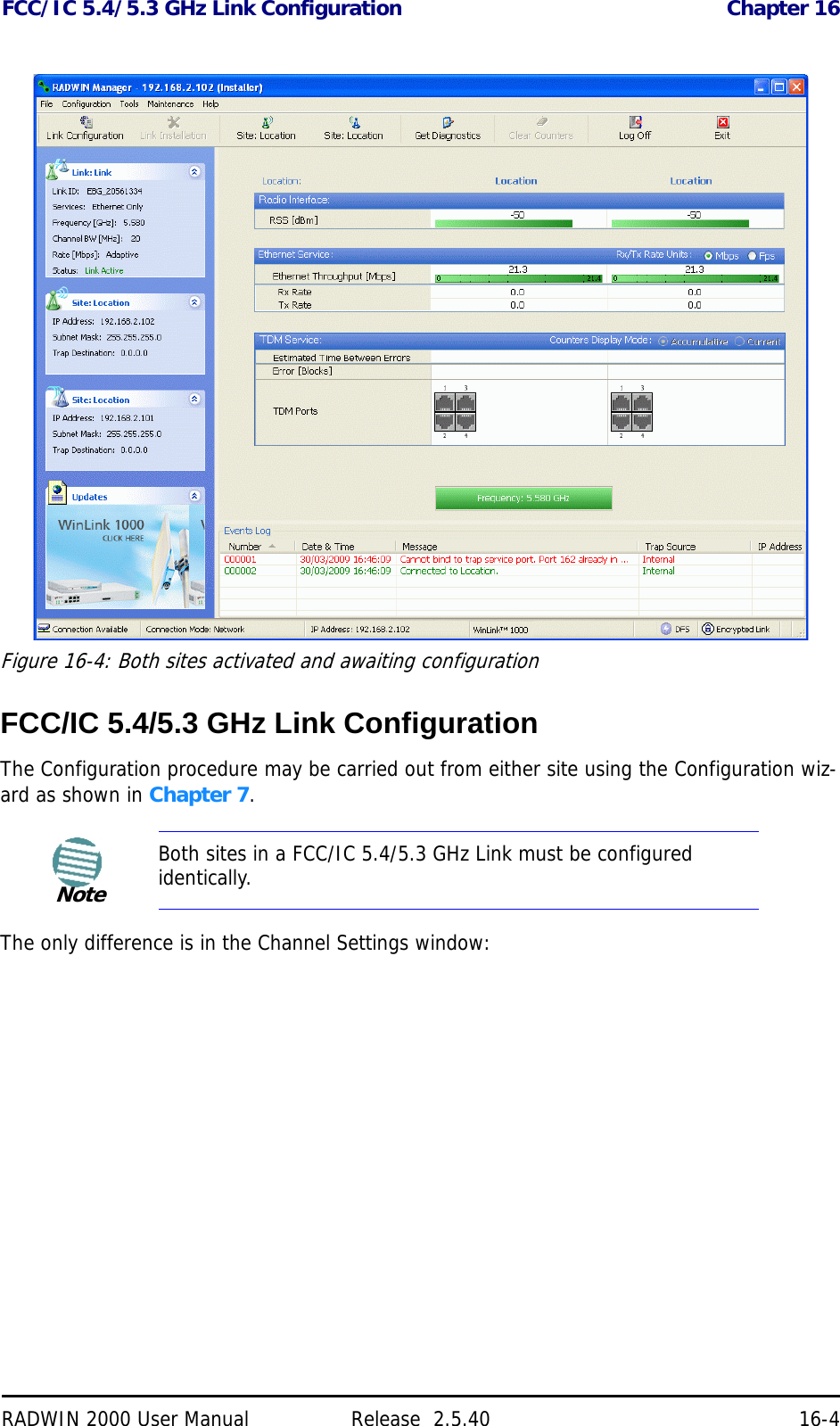
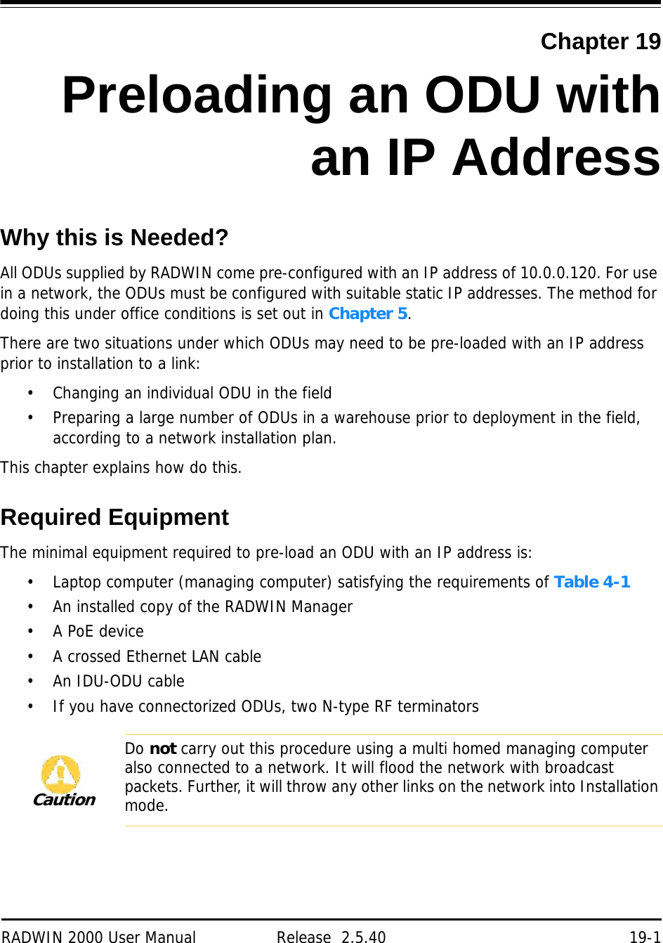
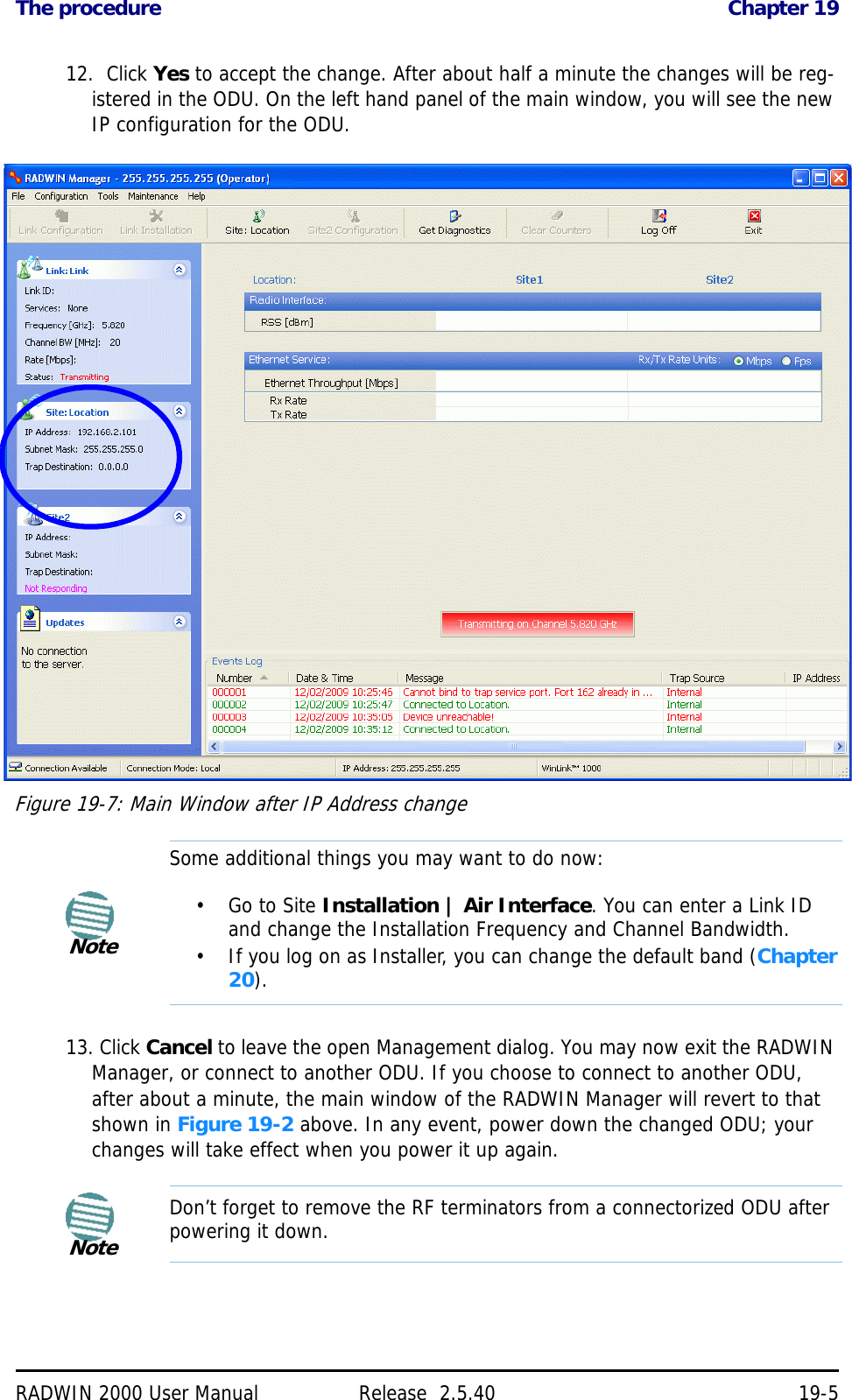
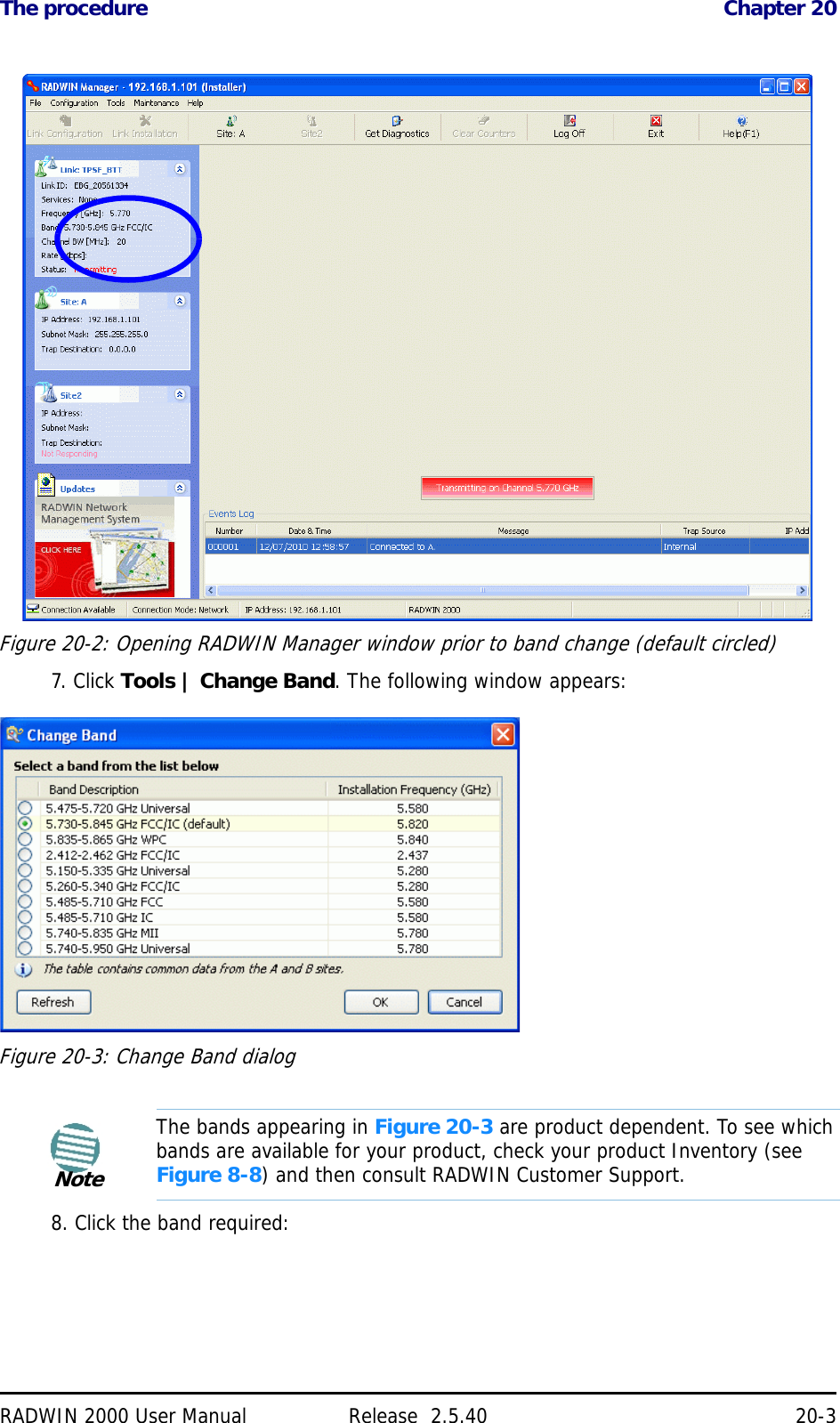
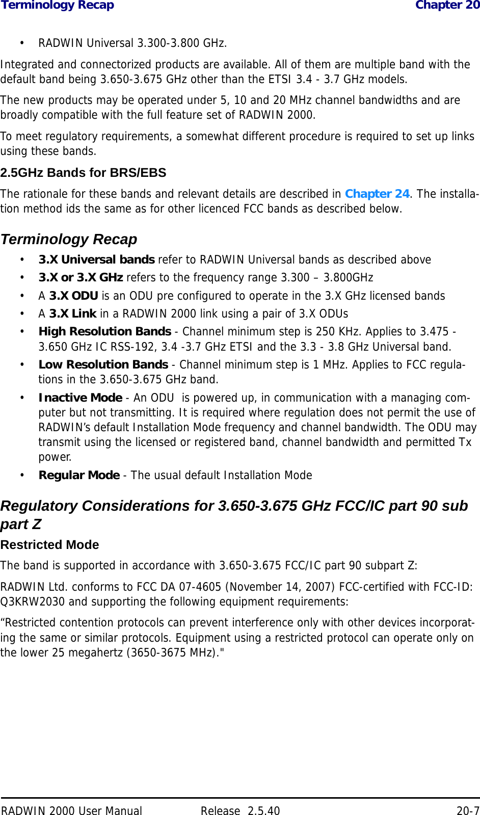
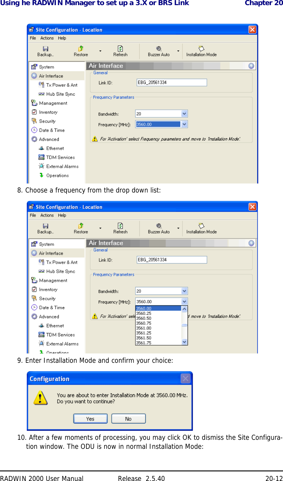
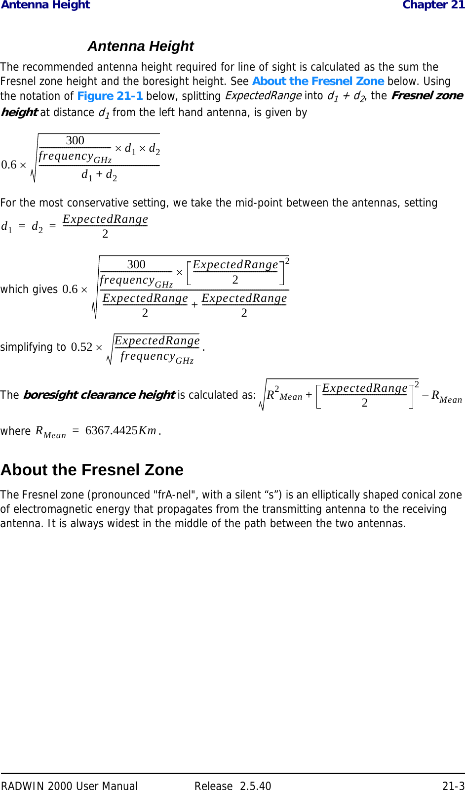
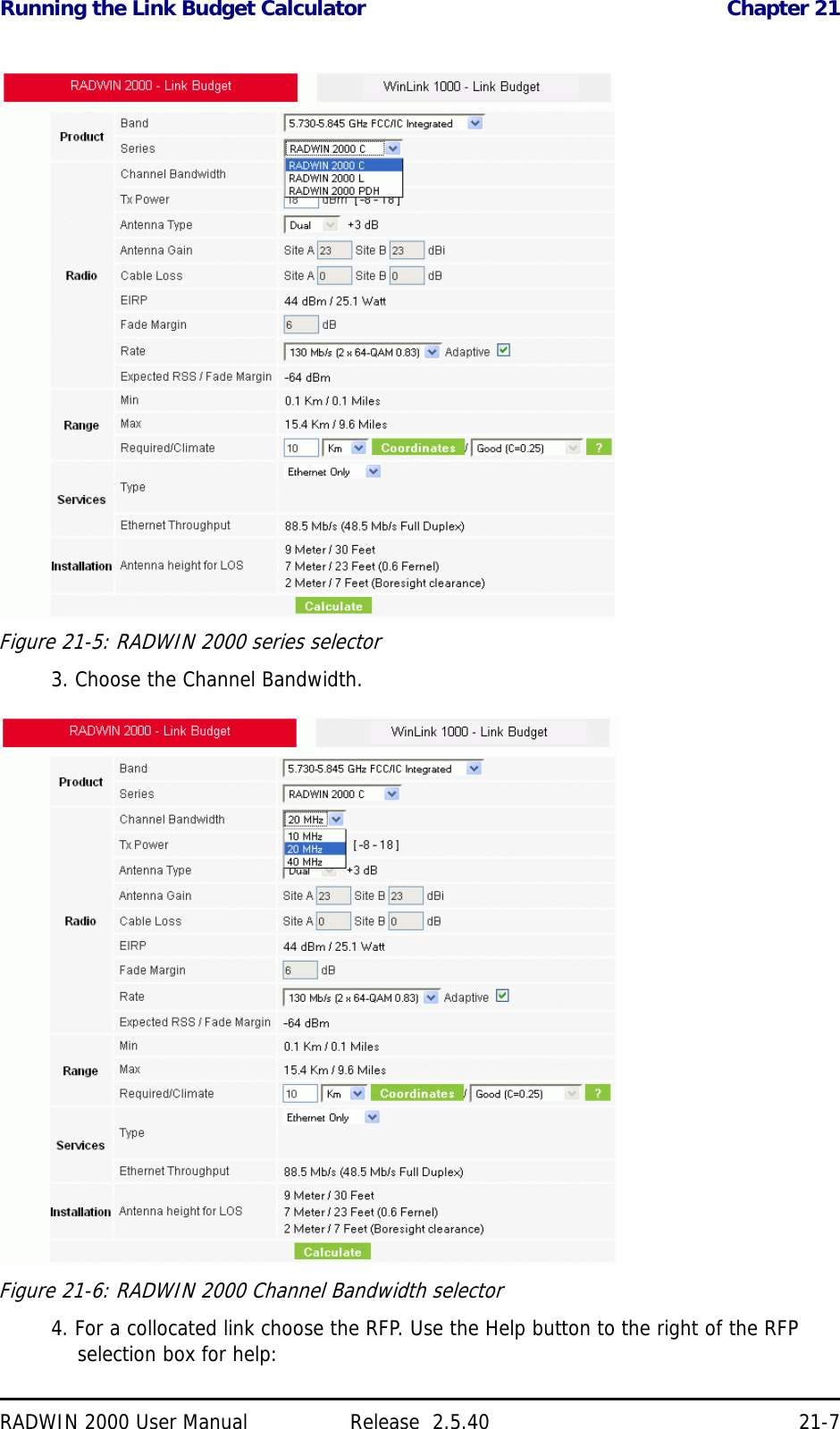
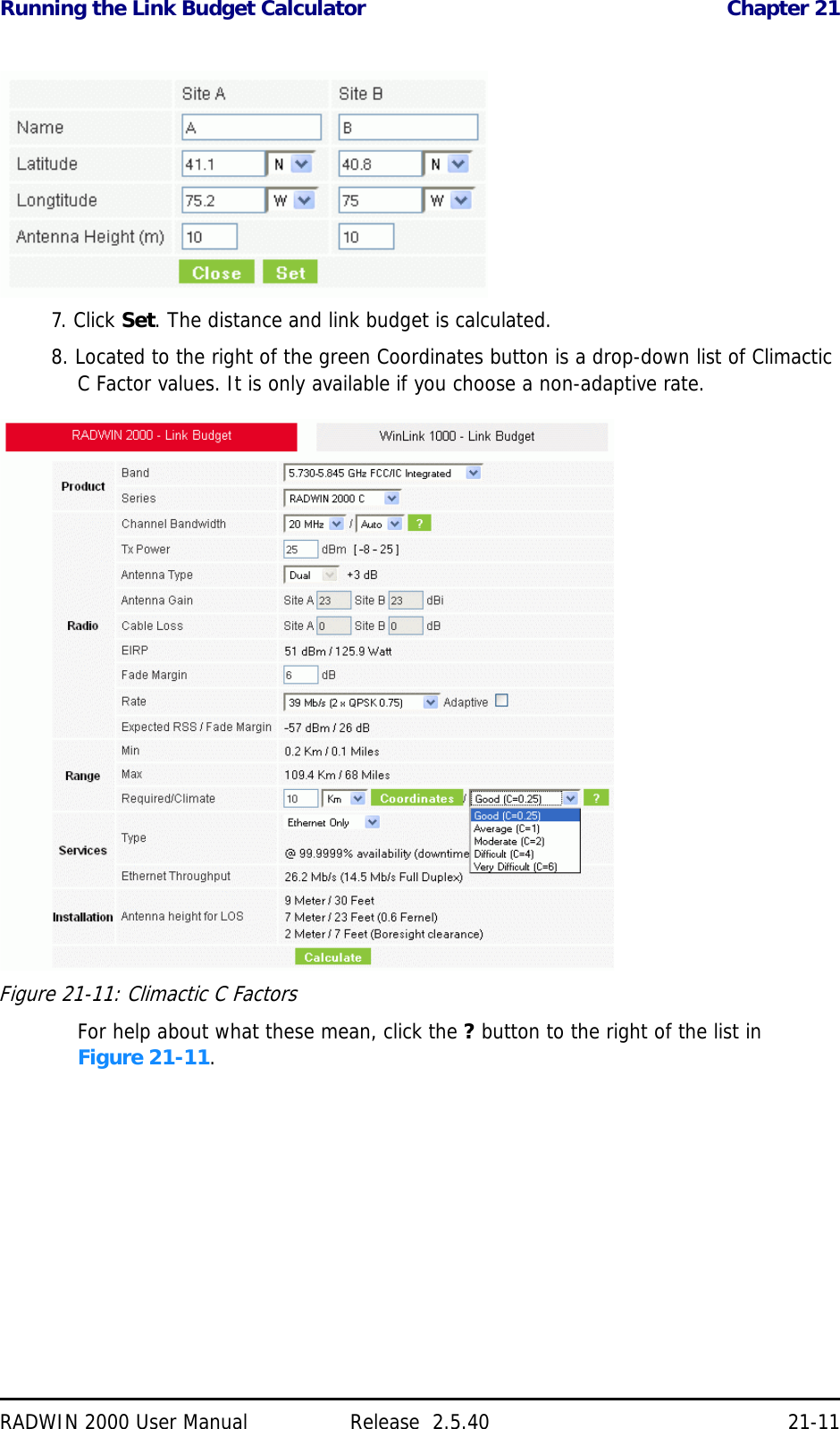
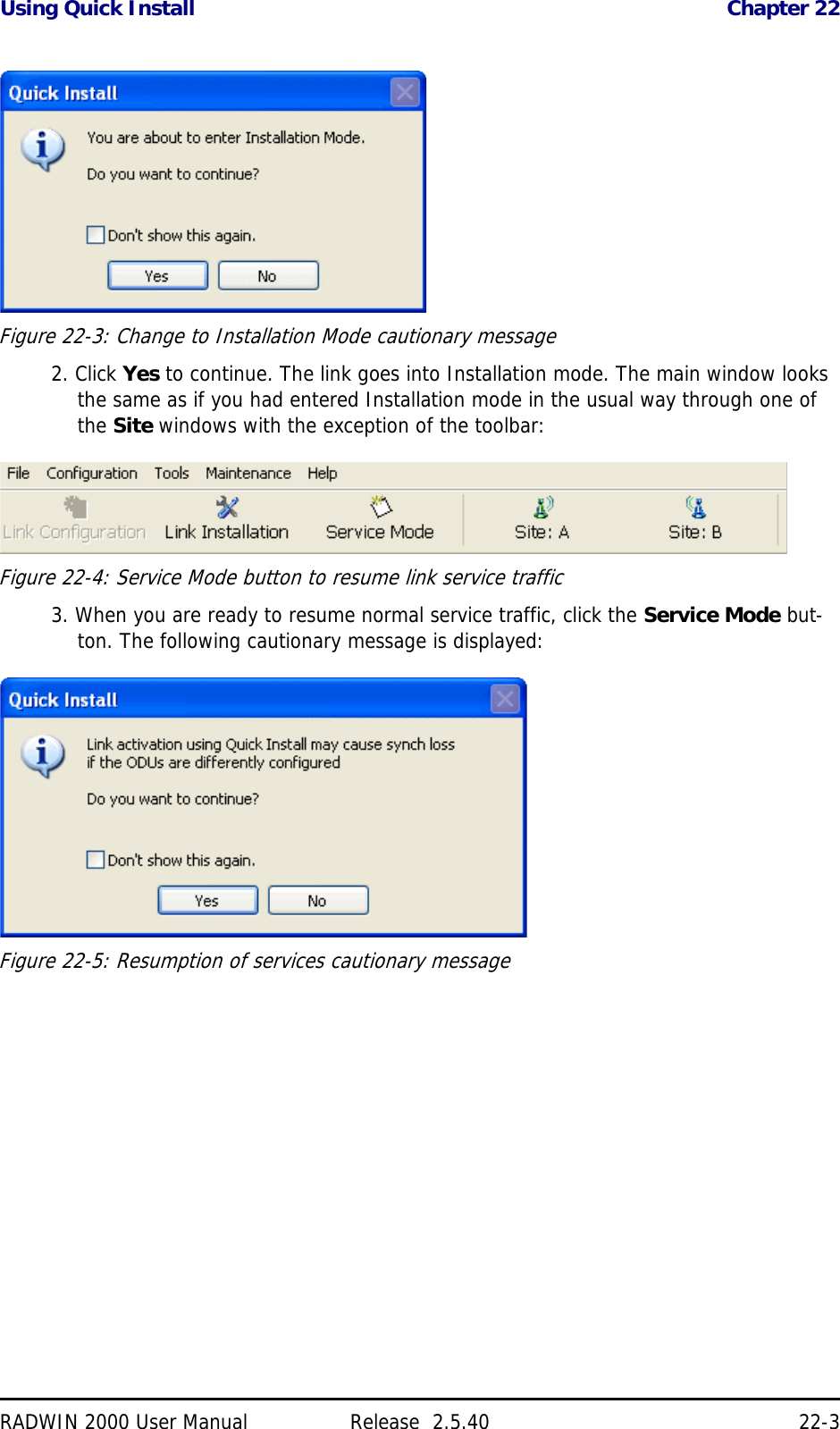
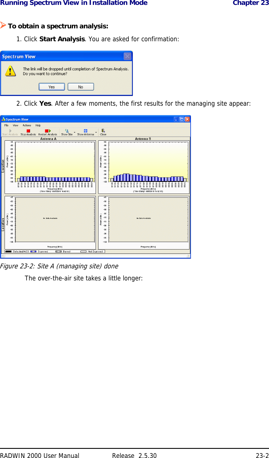
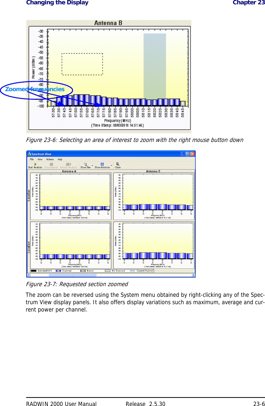
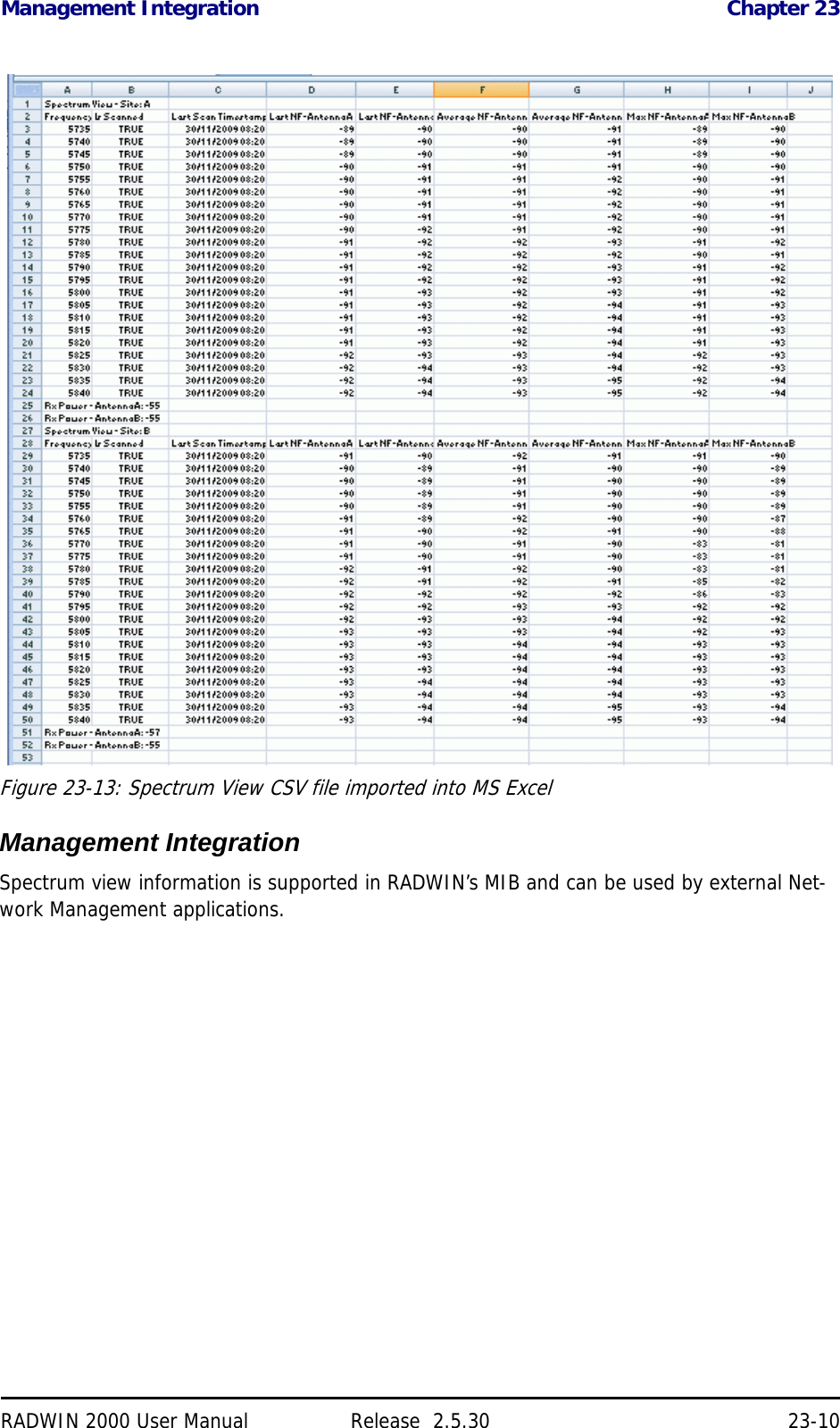
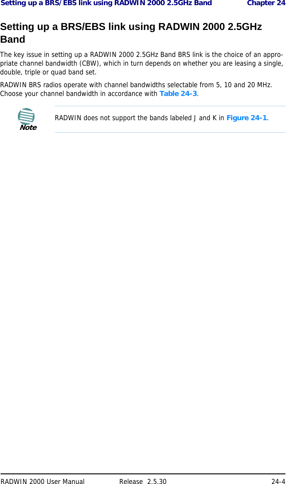
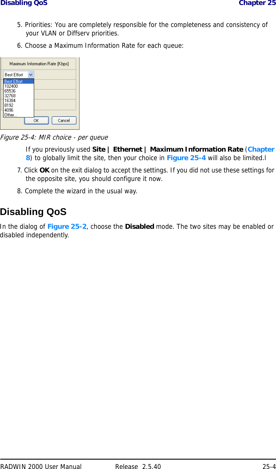
![RADWIN 2000 User Manual Release 2.5.40 F-1Appendix FRF ExposureThe antennas used for the following transmitters must be installed so as to provide a mini-mum separation distance from by-standers as specified in the following tables:Table F-1: Safety Distances for RADWIN 2000 FCC and IC ProductsFrequency Band [GHz] FCC ID IC ID Antenna gain [dBi] Min. Safety Distance [cm]5.8 Q3KRW2058 5100A-RW2054 28 2235.8 Q3KRW2058 5100A-RW2054 24 1415.3/5.4 Q3KRW2054 5100A-RW2054 23.5 / 28 204.9 Q3KRW2049 5100A-RW2054 28 2254.9 Q3KRW2049 5100A-RW2054 21 1132.4 Q3KRW2024 5100A-RW2054 19 392.4 Q3KRW2024I 5100A-RW2024I 17.5 402.5 Q3KRW2025 N/a 24 104.63.5 N/A 5100A-RW2030 25 923.6/3.7 Q3KRW2030 5100A-RW2030 25 86Table F-2: Safety Distances for RADWIN 2000 ETSI ProductsFrequency Band [GHz] Antenna gain [dBi] Min. Safety Distance [cm]5.8 24 / 28 205.4 23.5 / 28 205.3 23.5 / 28 202.4 19 / 17.5 203.5 25 200](https://usermanual.wiki/Radwin/RW2025.User-Manual-Part-2/User-Guide-1437359-Page-164.png)