Radwin RW2058U Outdoor radio unit operating in 5.8 GHz bands User Manual STW
Radwin Ltd. Outdoor radio unit operating in 5.8 GHz bands STW
UserManual.wiki
>
Radwin
>
RW2058U User Manual
>
Manual U3
Contents
1.
Manual U1
2.
Manual U2
3.
Manual U3
4.
Manual U4
5.
Manual
Manual U3
Navigation menu
Upload a User Manual
Namespaces
Wiki Guide
HTML
PDF
Info
Views
User Manual
Discussion / Help
Navigation
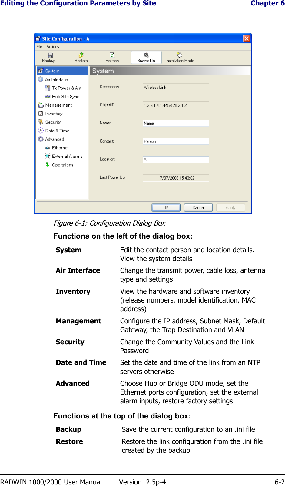
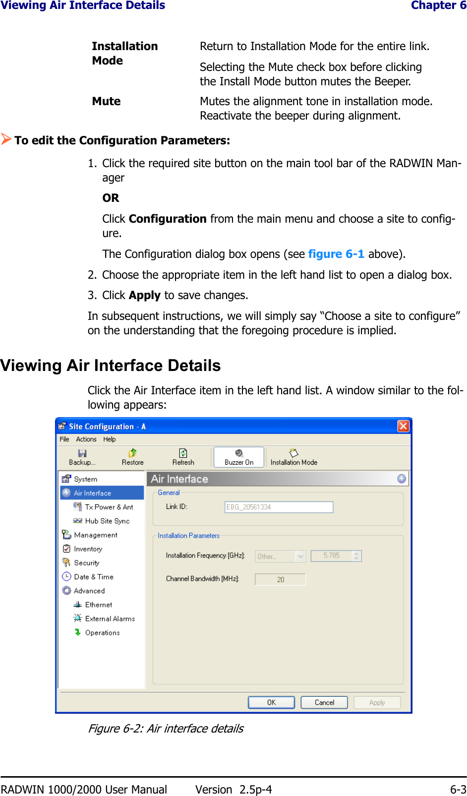
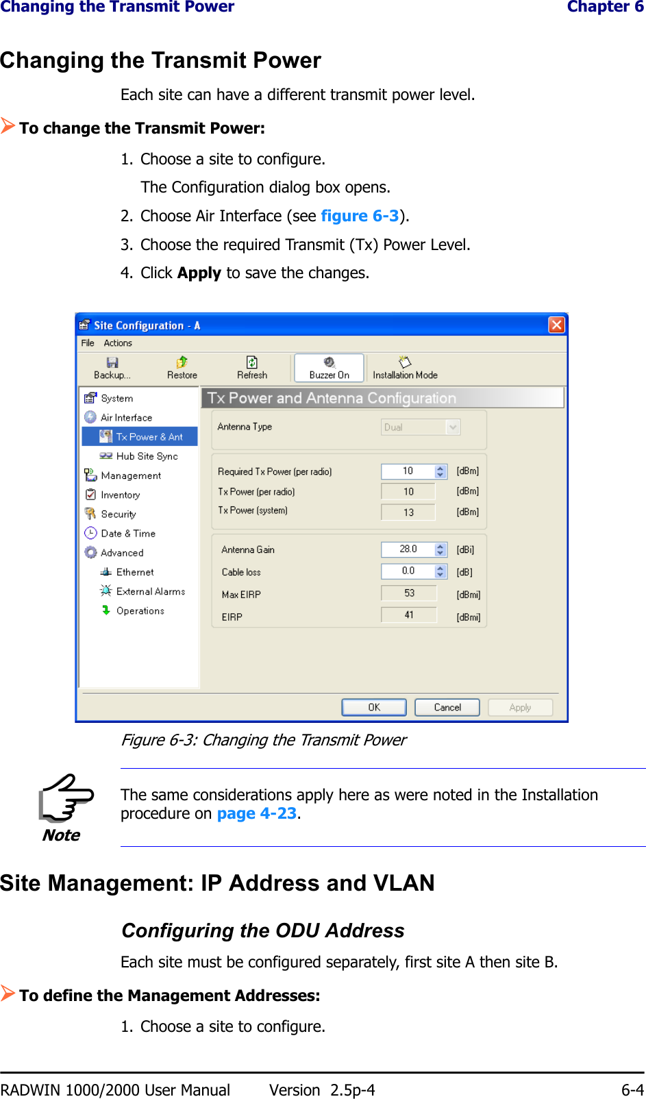
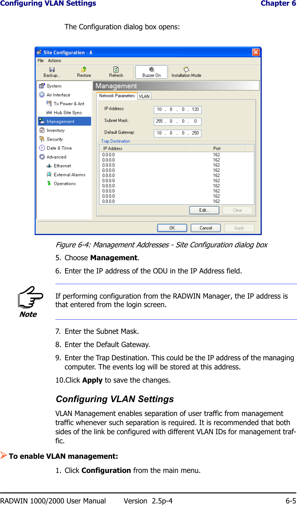
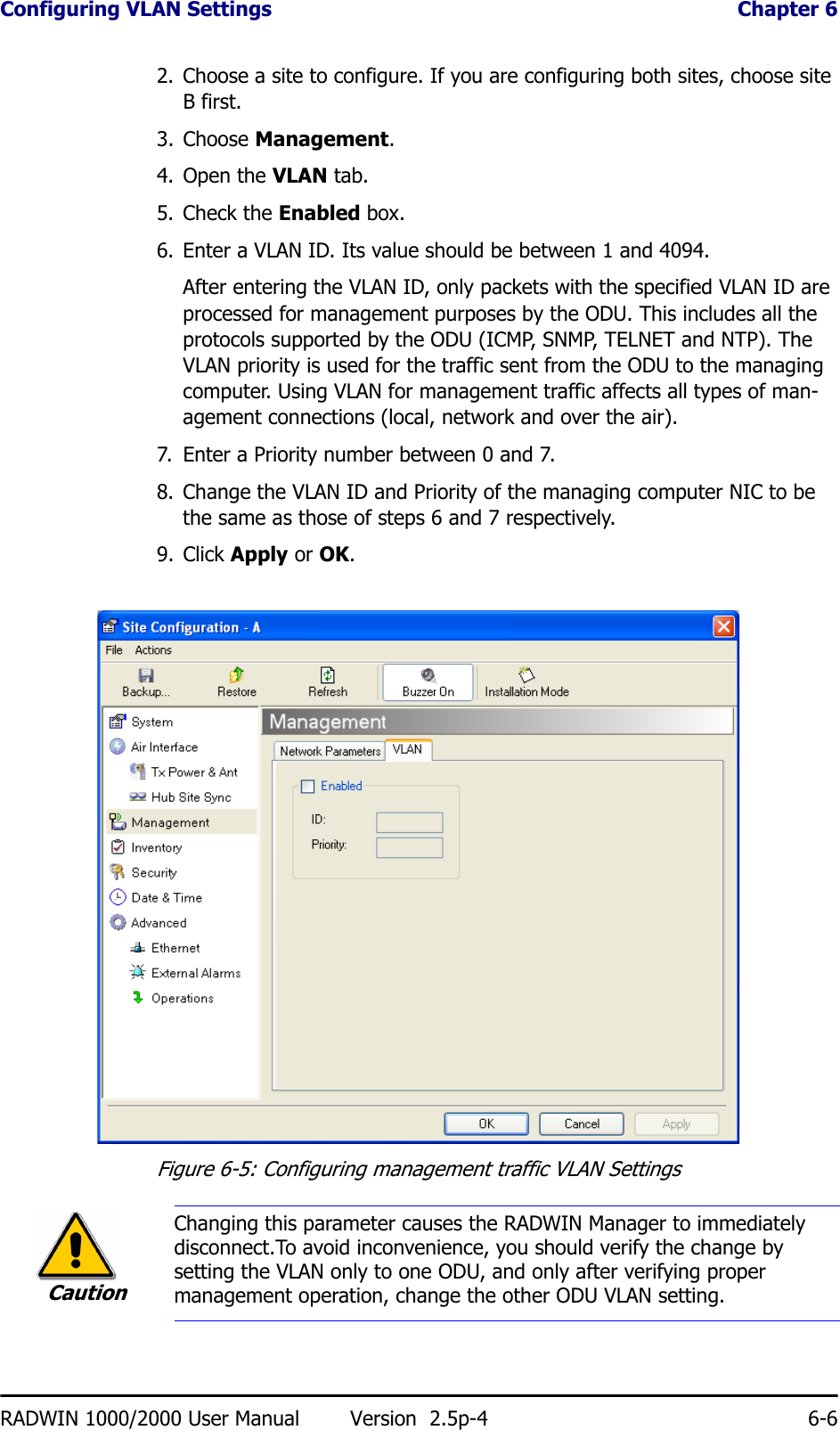
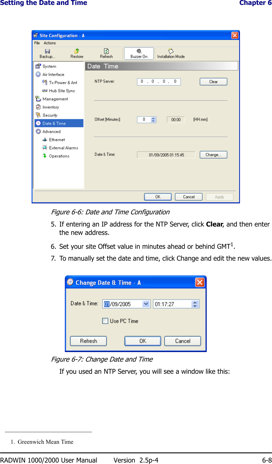
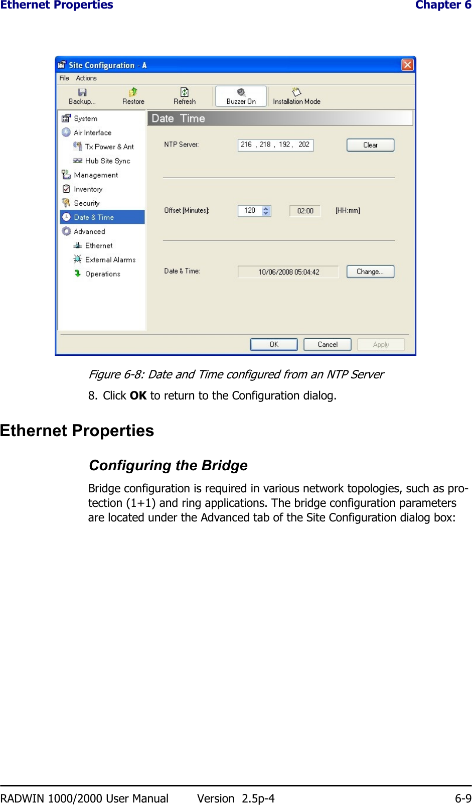
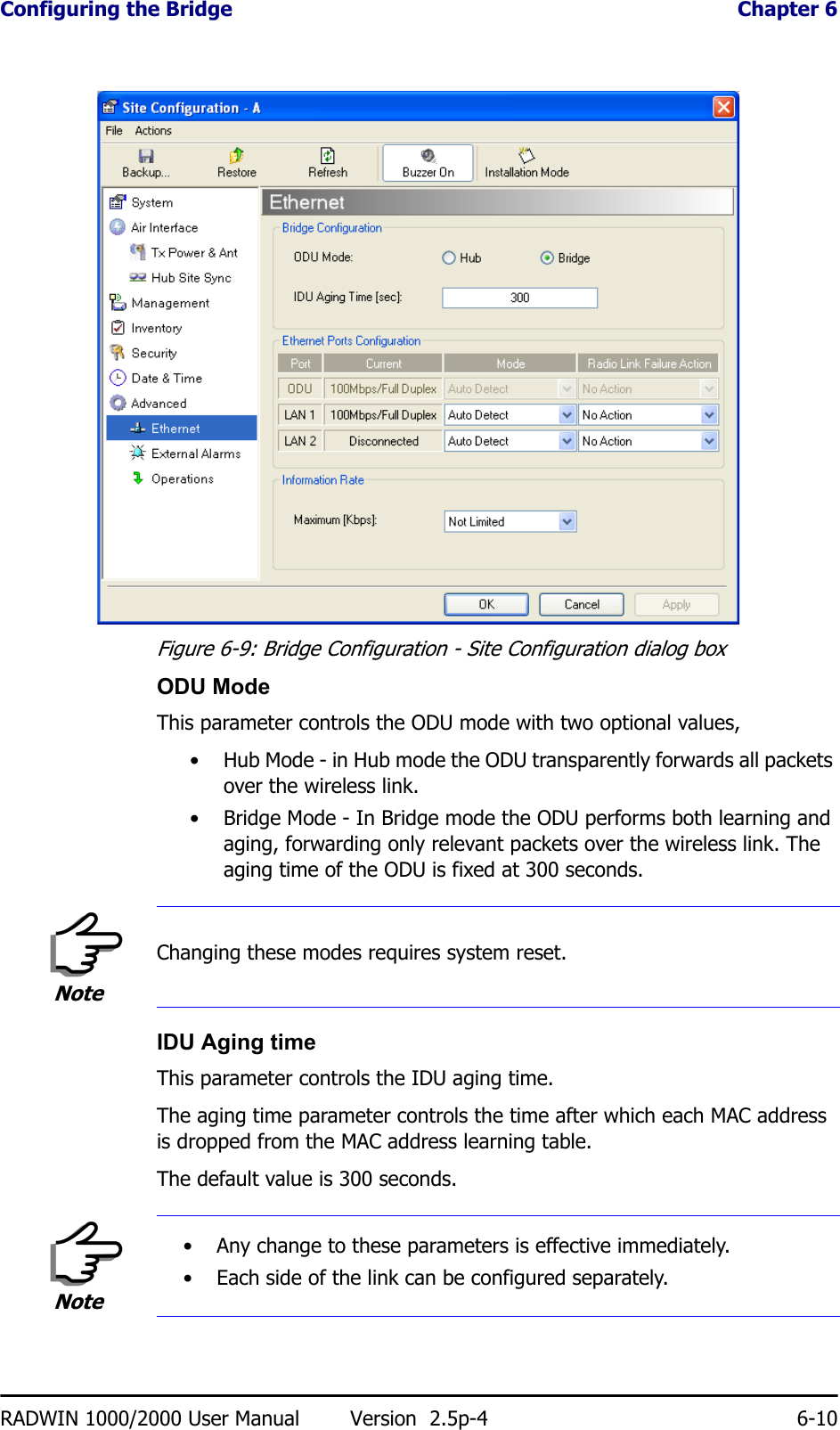
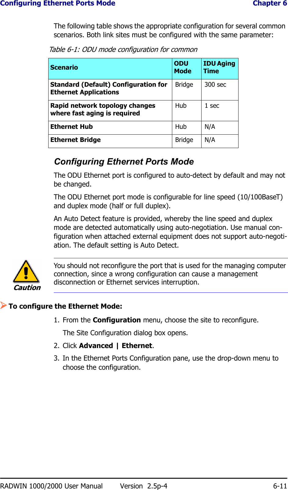
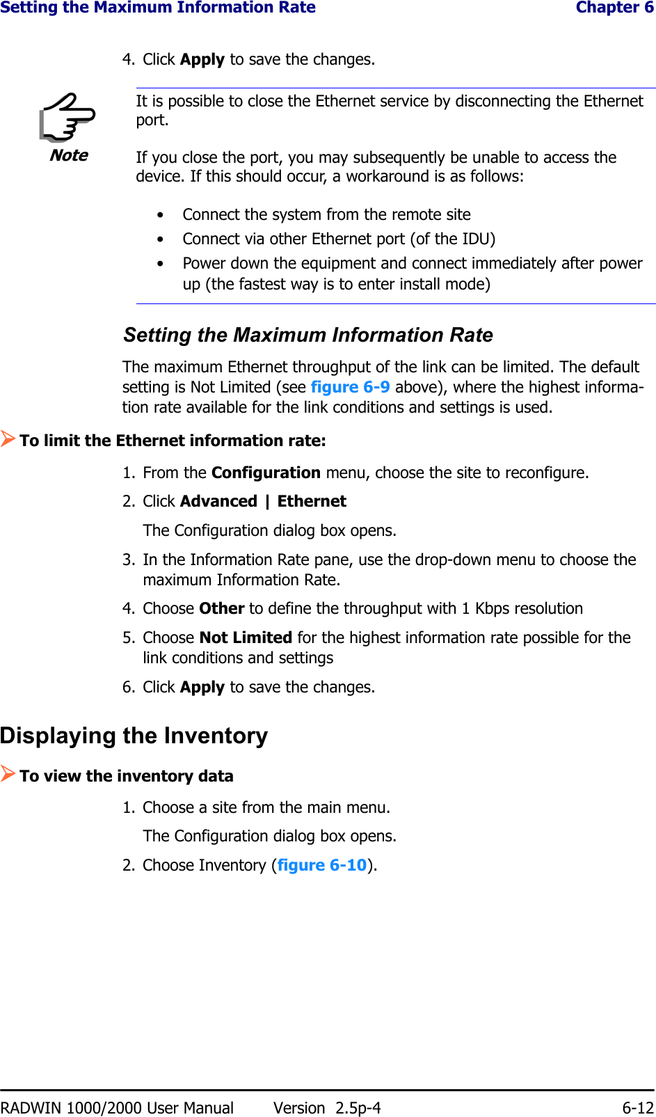
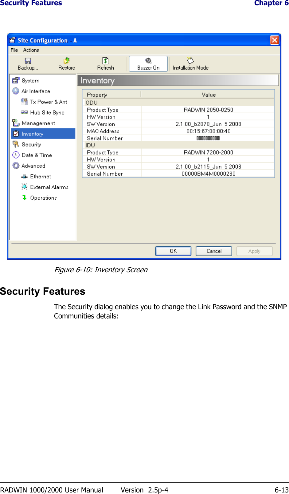
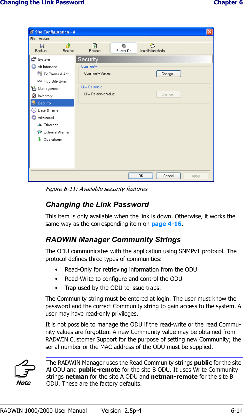
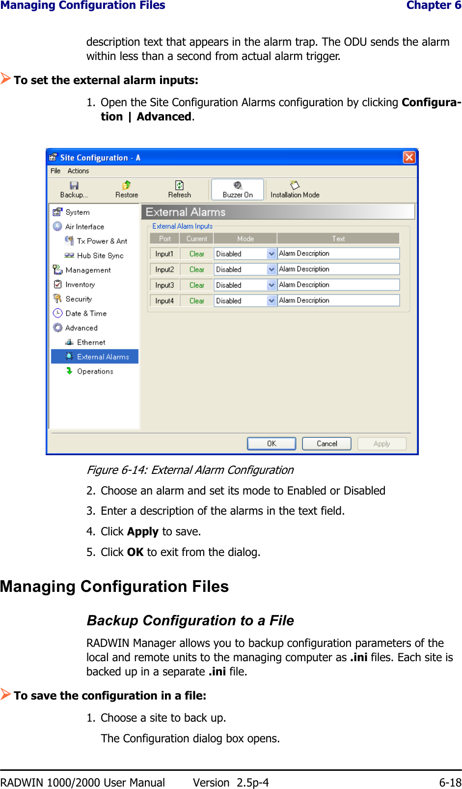
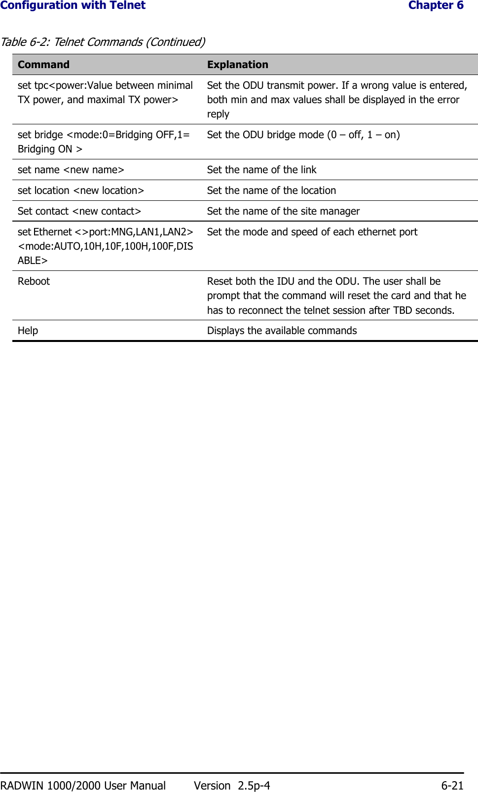
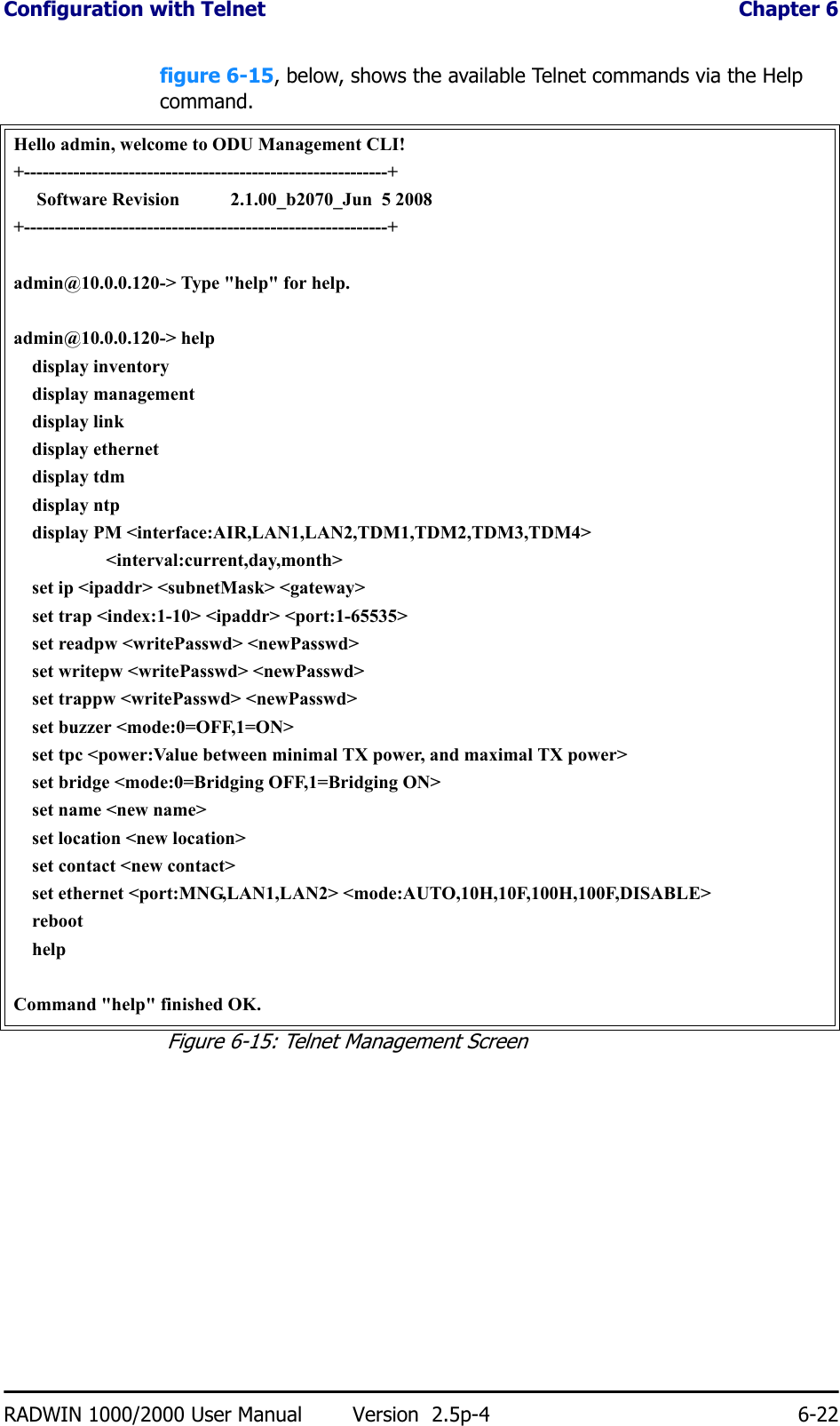
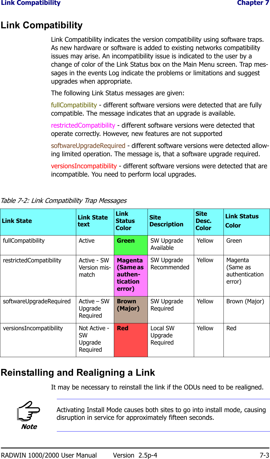
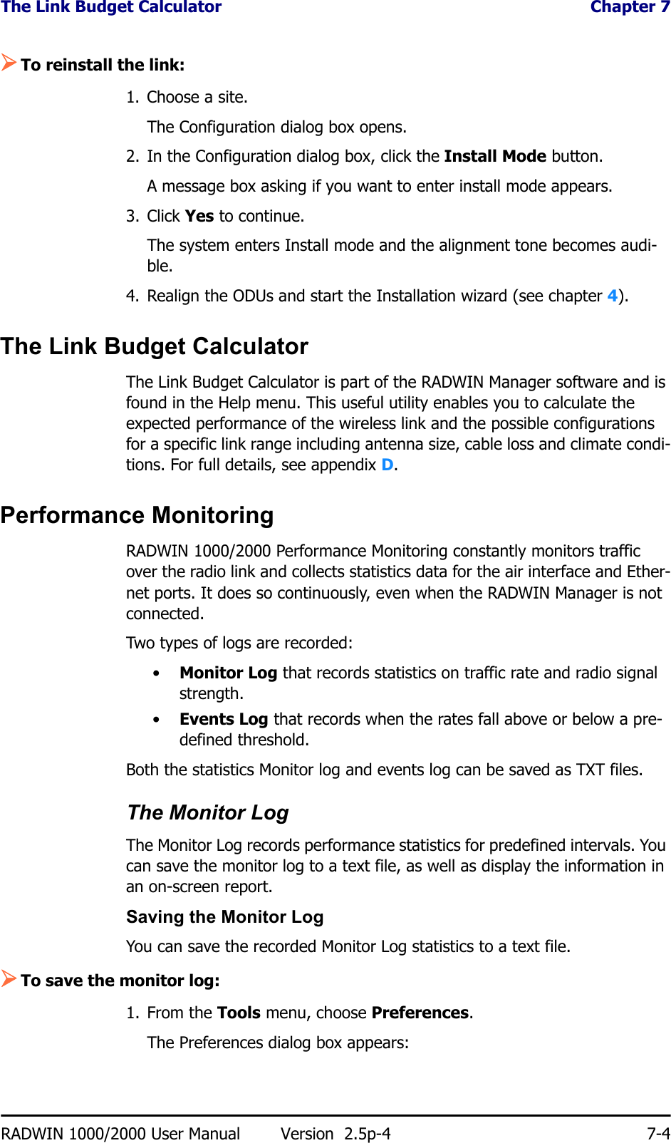
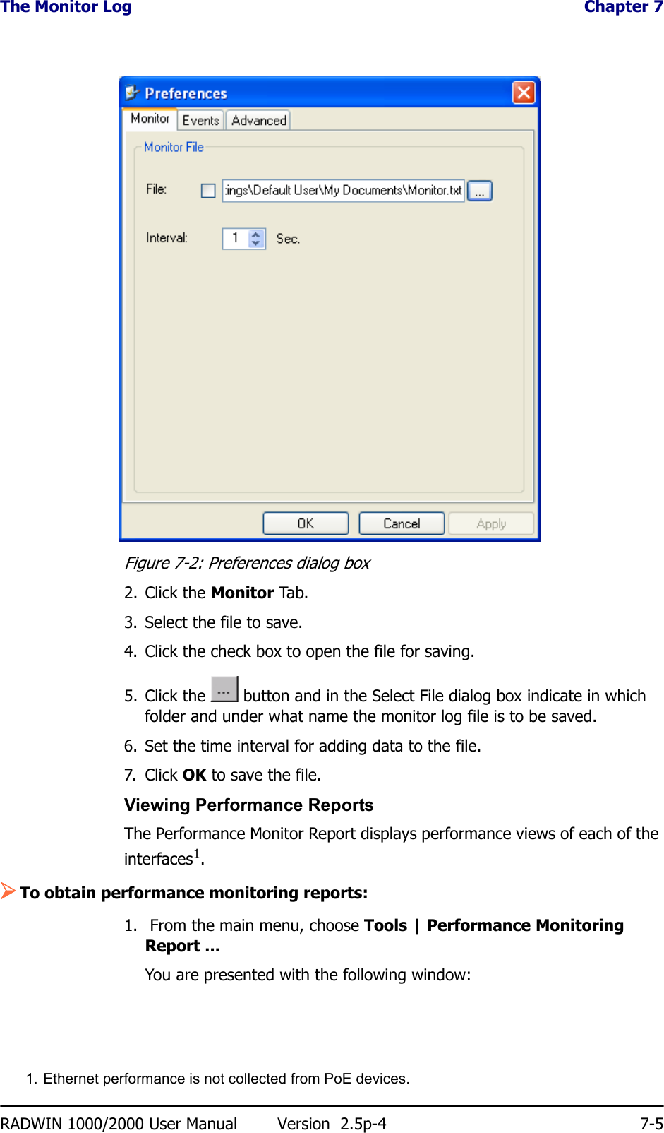
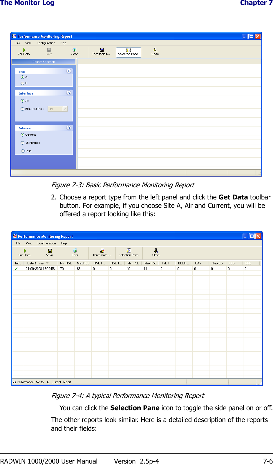
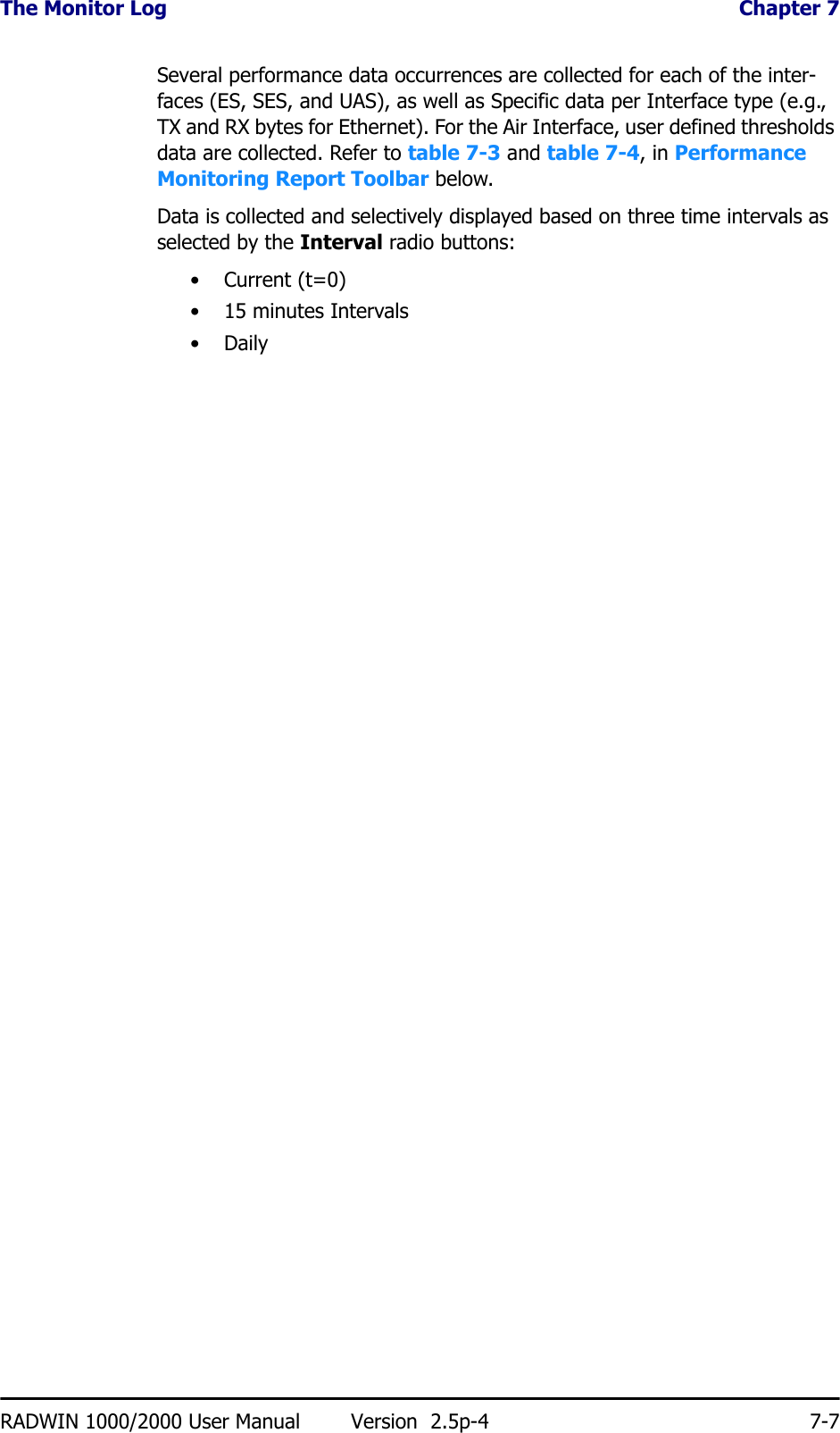
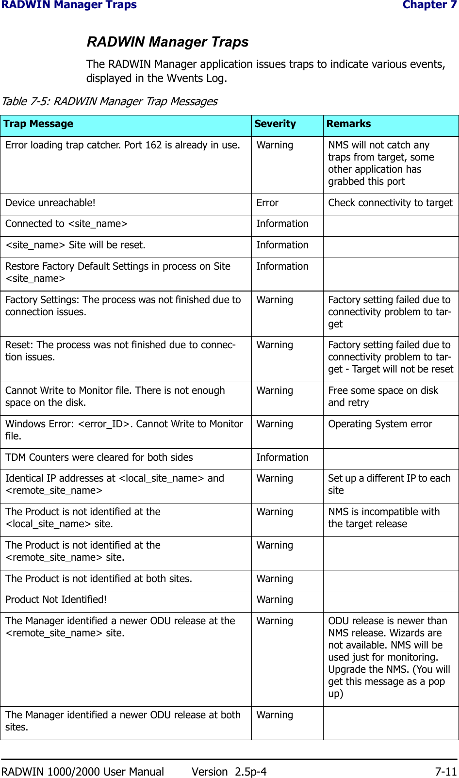
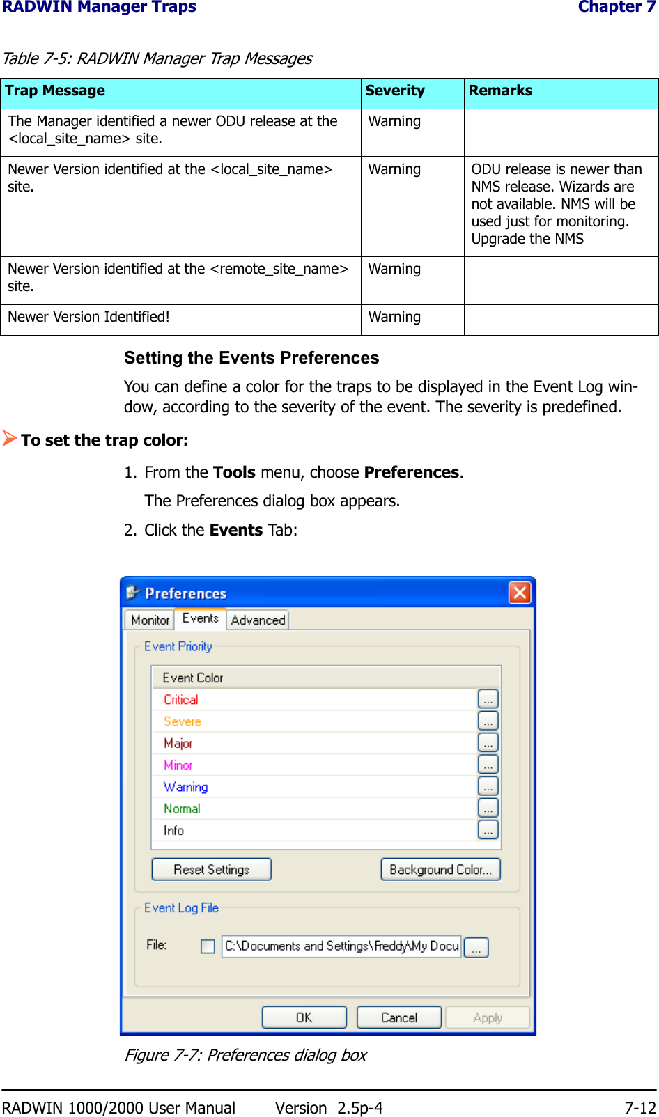
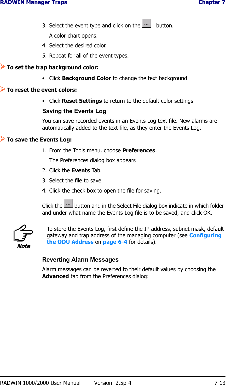
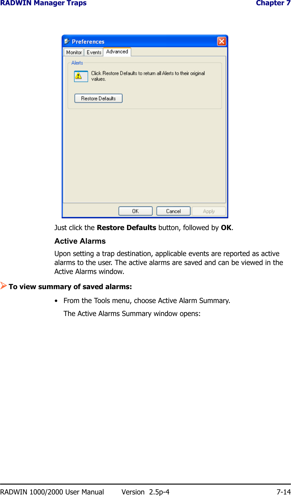
![Configuration with Telnet Chapter 6RADWIN 1000/2000 User Manual Version 2.5p-4 6-20Configuration with TelnetA Telnet terminal can be used to configure and monitor the RADWIN 1000/2000.To start a Telnet session, use telnet <manager IP>.For example, if you run Telnet as follows,telnet 10.0.0.120you will be asked for a user name and password.The login user name/password is identical to the Community strings; Read allows display only, Read/Write allows display and set commands.Supported Telnet commands are shown in table 6-2. Note that some of the commands are model-specific. For example, TDM commands will not apply to Ethernet only and PoE based links.Table 6-2: Telnet CommandsCommand Explanationdisplay inventory Displays ODU product name, Name, Location, hardware and software revisions, uptime, MAC address, IDU product name, IDU software and hardware revisionsdisplay management Displays IP, Subnet, Gateway, Traps tabledisplay link Displays State, Link ID, Channel BW, RSS, TSL, Frequency/ACS, DFS, Rate/ARA, Distancedisplay Ethernet Displays Bridge Mode, Aging time, Port table (State, Status and action)display tdm Displays Clock Mode, Master Clock Mode, Current Clock, Quality[1], TDM table (Line status, Error Blocks)display ntp Displays Time, Server and Offsetset ip <ipaddr> <subnetMask> <gateway>Set the ODU IP address, subnet mask and gatewayThe user must reset the ODU after the command completiondisplay PM <interface:AIR,LAN1,LAN2,TDM1,TDM2,TDM3,TDM4> <interval:current,day,month>Shows the performance monitor tables for each interface according to user defined monitoring intervalsset trap <index:1-10> <ipaddr> <port:0-65535>Set a specific trap from the traps table (set trap 3 10.0.0.133 162)set readpw <oldpasswd> <passwd> Set the read access password (Read Community)set writepw <oldpasswd> <passwd> Set the read-write access password (Read-Write Community)set trappw <oldpasswd> <passwd> Set the trap Community stringset buzzer <mode:0=OFF,1 =ON> Toggle the buzzer mode (0 – off, 1 – on)](https://usermanual.wiki/Radwin/RW2058U.Manual-U3/User-Guide-1314854-Page-20.png)