Raytheon IIS ARTU Air-Ground Radio System User Manual installation manual part seven
Raytheon Company Air-Ground Radio System installation manual part seven
UserManual.wiki
>
Raytheon IIS
>
ARTU User Manual
>
installation manual part seven
Contents
1.
installation manual part one
2.
installation manual part two
3.
installation manual part three
4.
installation manual part four
5.
installation manual part five
6.
installation manual part six
7.
installation manual part seven
installation manual part seven
Navigation menu
Upload a User Manual
Namespaces
Wiki Guide
HTML
PDF
Info
Views
User Manual
Discussion / Help
Navigation
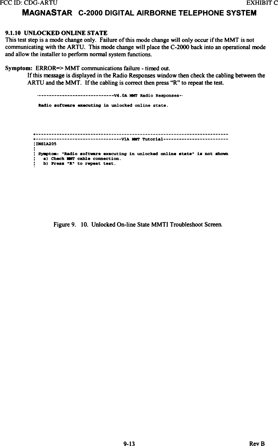
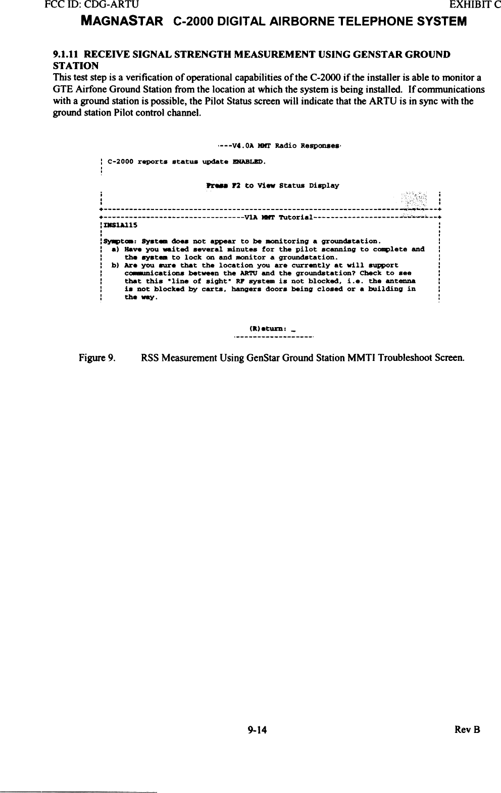
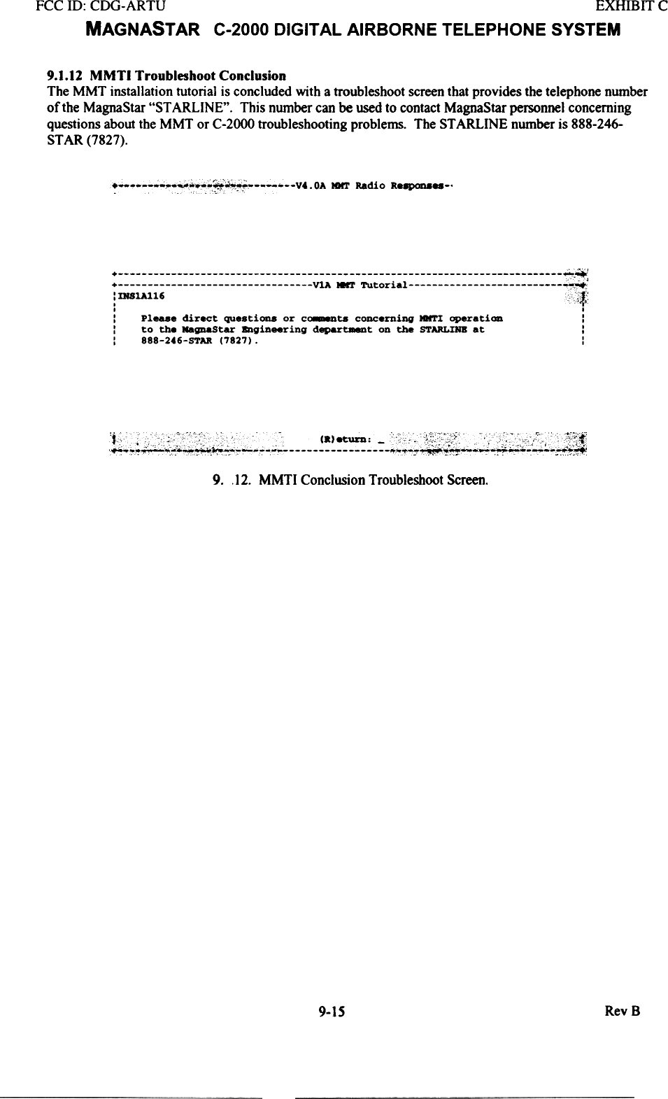
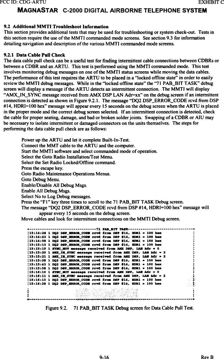
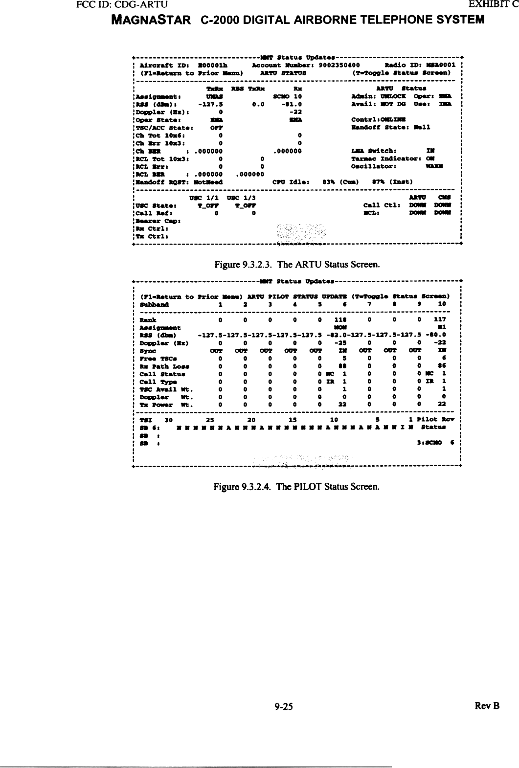
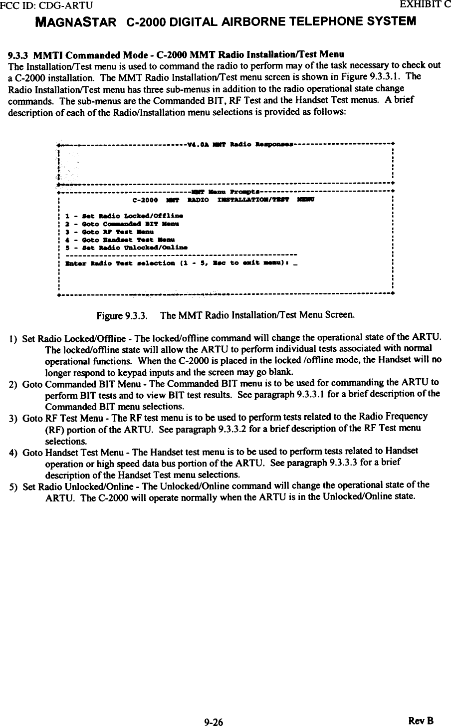
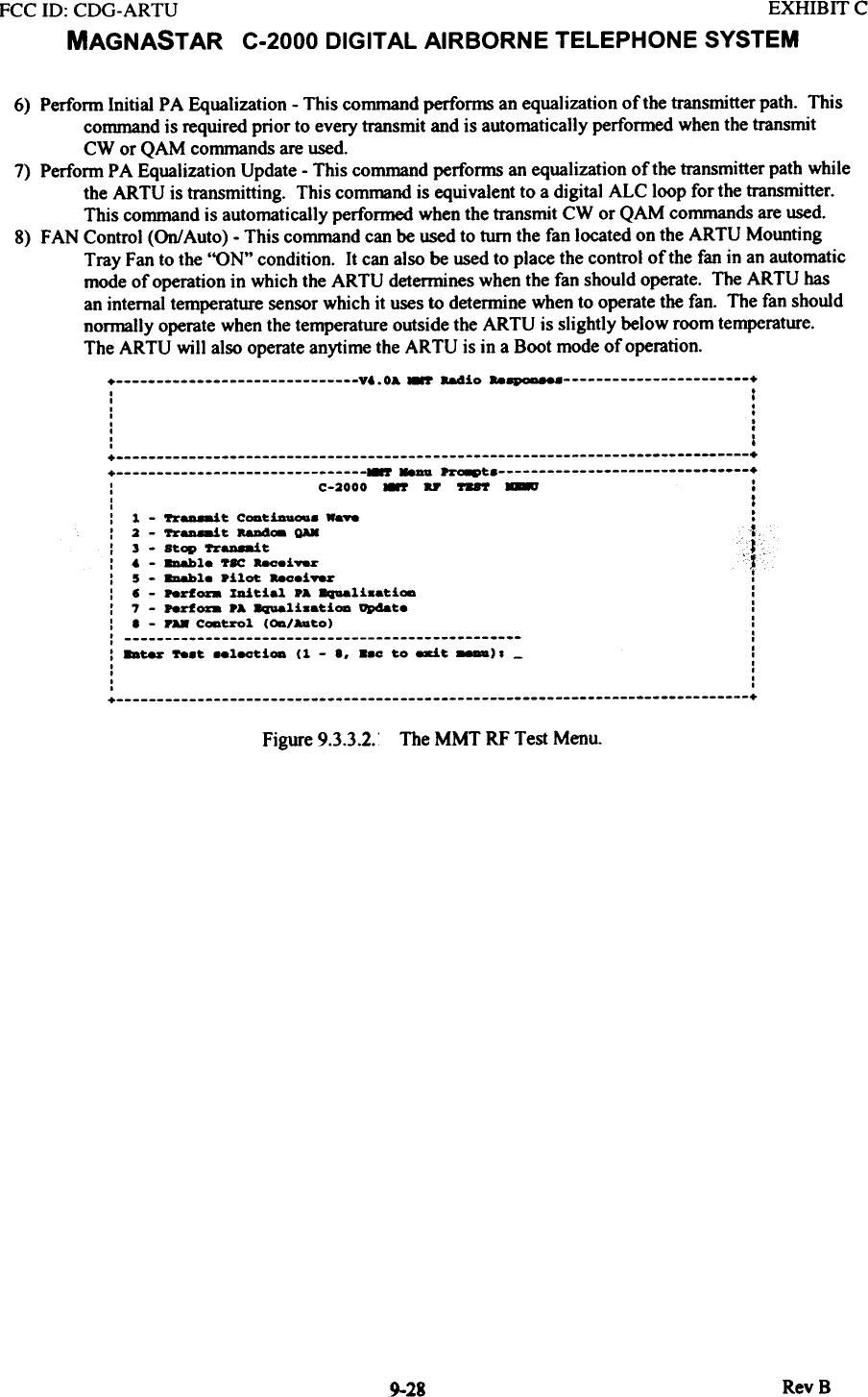
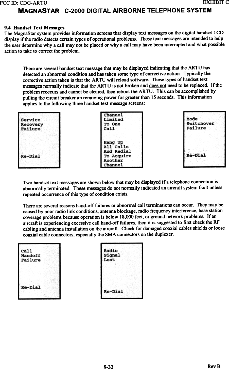
![FCC ID: CDG-ARTU EXHIBIT CMAGNASTAR C-2000 DIGITAL AIRBORNE TELEPHONE SYSTEMA brief description oftbe9.3.3.1 C-2000 MMT Commanded BIT MenuThe MMT Commanded BIT menu screen is shown in Figure 9.3.3,Commanded BIT selections are as follows:0) View Results - By pressing zero, it is possible to view the BIT test results after BIT testing hascompleted.I) Full BIT - This command will cause the ARTU to run the Full Built-In-Test that is nonnally run uponpower-up.2) External TDM Loopback - This command will perform a test to check the transmit driver and the linereceiver of the high speed data bus interface. The transmit outputs (+ and -) must be physicallylooped back on the receive inputs in order for this test to pass.+ V&.OA ~ R84io ..~ +. I. I. .. .. .. .+ ++ ~ -.au ~ +I C-2000 .., ~~ .%~ - :t !: 1 - ..11 ax": 2 - -~ .,. roo.-k: : 8Bt.- ax" _l_t.i- (1 - 2. 0 t.o ri- ...~t." - t.o ~t. _)1 -IIII,,!Figme 9.3.3.1 The MMT Commanded BIT Menu Screen9.3.3.2 C-2000 MMT RF Test MenuThe MMT RF Test menu screen is shown in Figure 9.3.3.2.selections are as fo\lows:A brief description of the Commanded BIT1) Transmit Continuous Wave - This command will make the ARTU transmit a continuous wave signal.This command should be used when checking the ARTUs frequency accuracy. The transmitteroutput power level of the ARTU will be]O watts (+40 dBm) minimum with zero dB ofprogrammed attenuation.The user will be asked to enter the value of attenuation (0-40 dB). Also, the user will be askedwhat frequency to transmit on ( subband (1-10) and channel (1-29) or enter "0" for manual entrywith a resolution to 2 kHz).2) Transmit Random QAM - This command will make the ARTU transmit a modulated 16 QAM signal.The transmitter output power level of the ARTU will be ] 0 watts (+40 dBm) average power withzero dB of programmed attenuation. This QAM signal may have peak output power as high as 60wattsThe user will be asked to enter the value of attenuation (0-40 dB). Also, the user will be askedwhat frequency to transmit on (subband (]-10) and channel (]-29) or enter "0" for manual entrywith a resolution to 2 kHz).3) Stop Transmit - This command will cause the ARTU to stop transmitting. It will also disable a receiverif the receiver has been enabled.4) Enable TSC Receiver - This command will enable the TSC (voice channel) receiver. The user will beasked what frequency to tune the receiver (subband (]-]O) and channel (1-29) or enter "0" formanual entry with a resolution to 2 kHz).5) Enable Pilot Receiver - This command will enable the Pilot (pilot scanning) receiver. The user will beasked what frequency to tune the receiver (subband (]-]O) and channel (1-6) or enter "0" formanual entry with a resolution to 2 kHz).9-27 RevS](https://usermanual.wiki/Raytheon-IIS/ARTU.installation-manual-part-seven/User-Guide-257065-Page-15.png)