Raytheon IIS ARTU Air-Ground Radio System User Manual installation manual part two
Raytheon Company Air-Ground Radio System installation manual part two
UserManual.wiki
>
Raytheon IIS
>
ARTU User Manual
>
installation manual part two
Contents
1.
installation manual part one
2.
installation manual part two
3.
installation manual part three
4.
installation manual part four
5.
installation manual part five
6.
installation manual part six
7.
installation manual part seven
installation manual part two
Navigation menu
Upload a User Manual
Namespaces
Wiki Guide
HTML
PDF
Info
Views
User Manual
Discussion / Help
Navigation
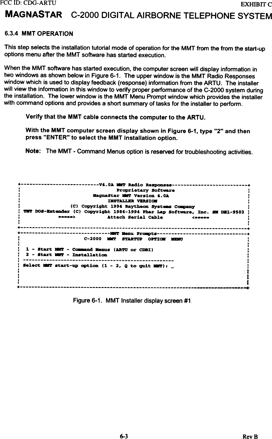
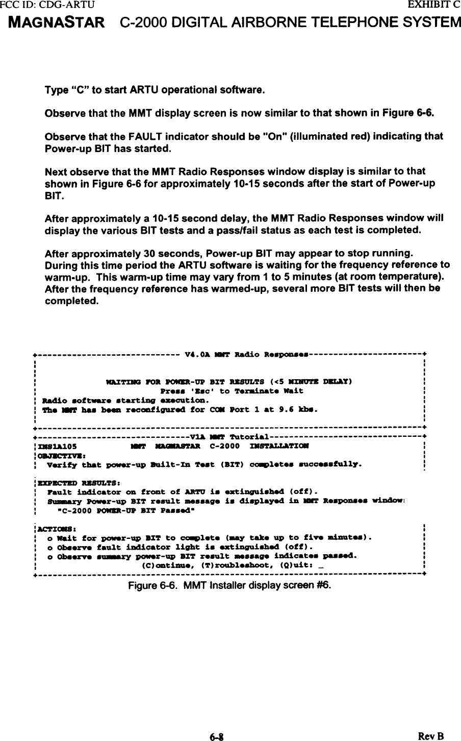
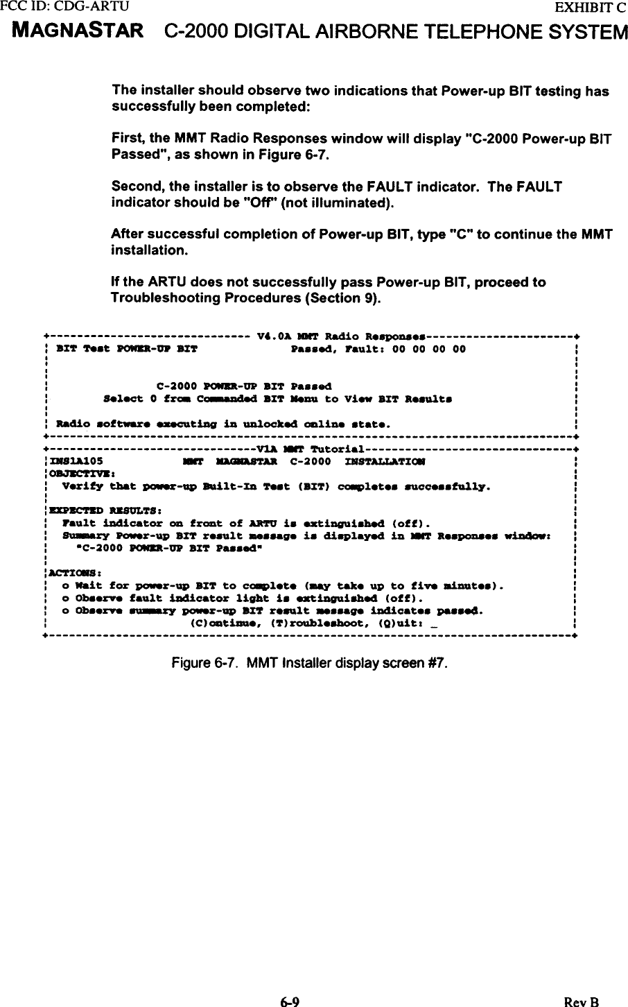
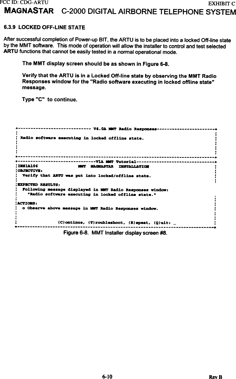
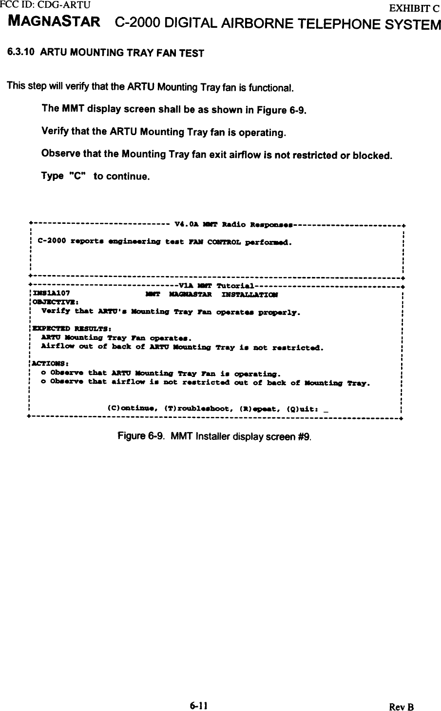
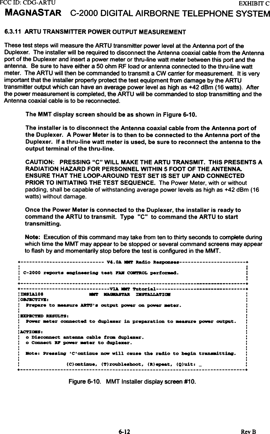
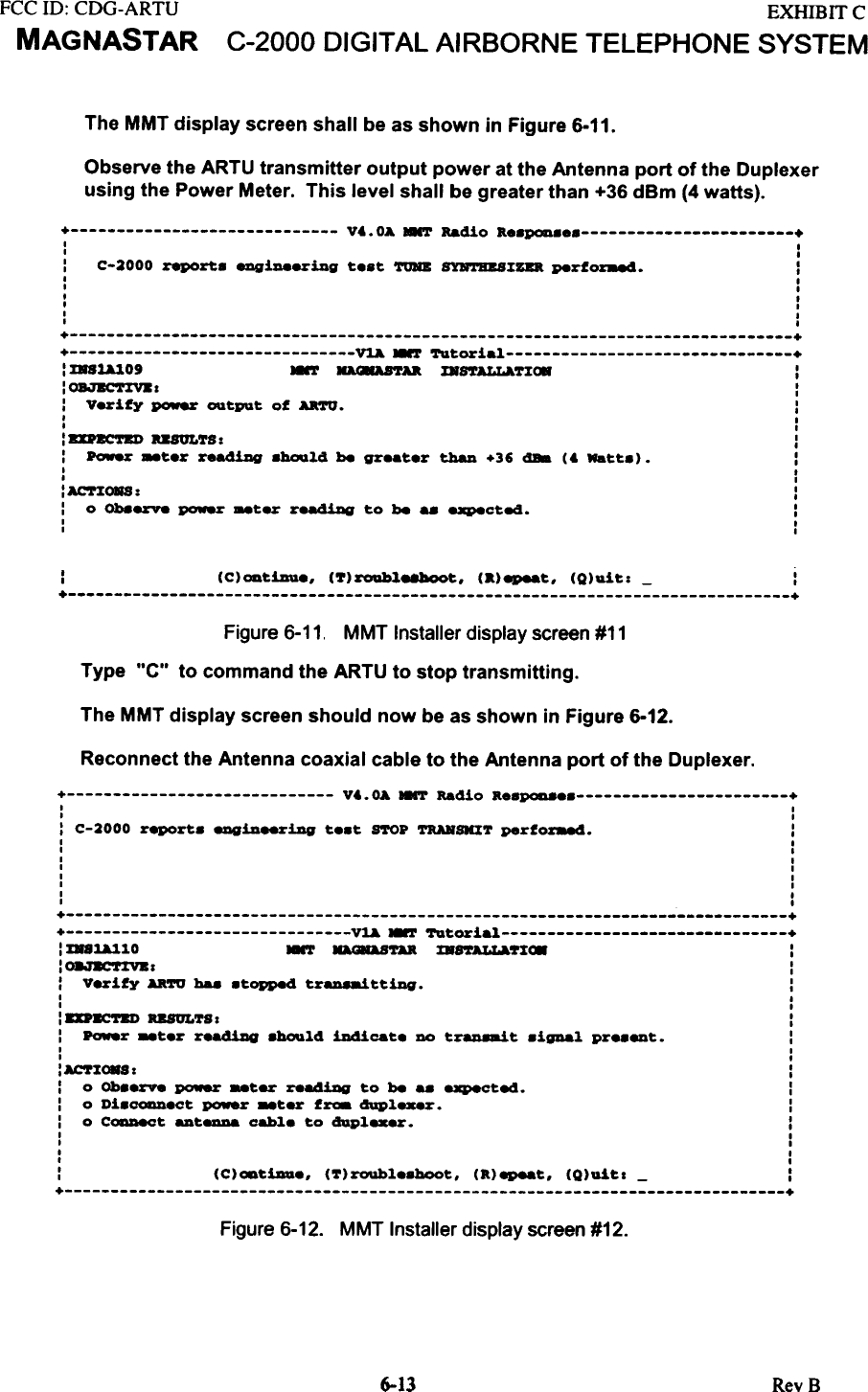
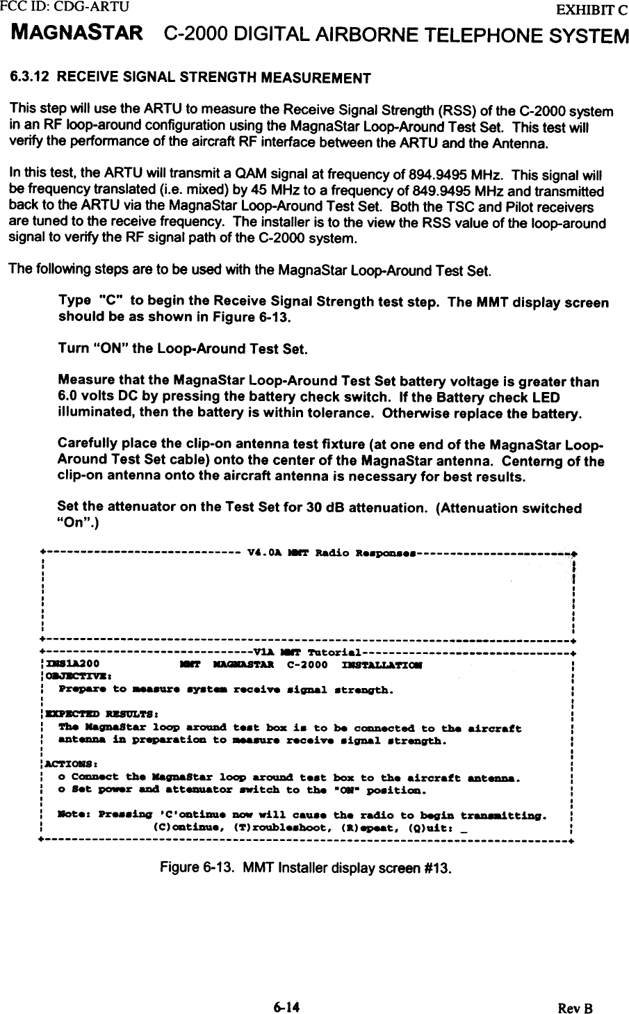
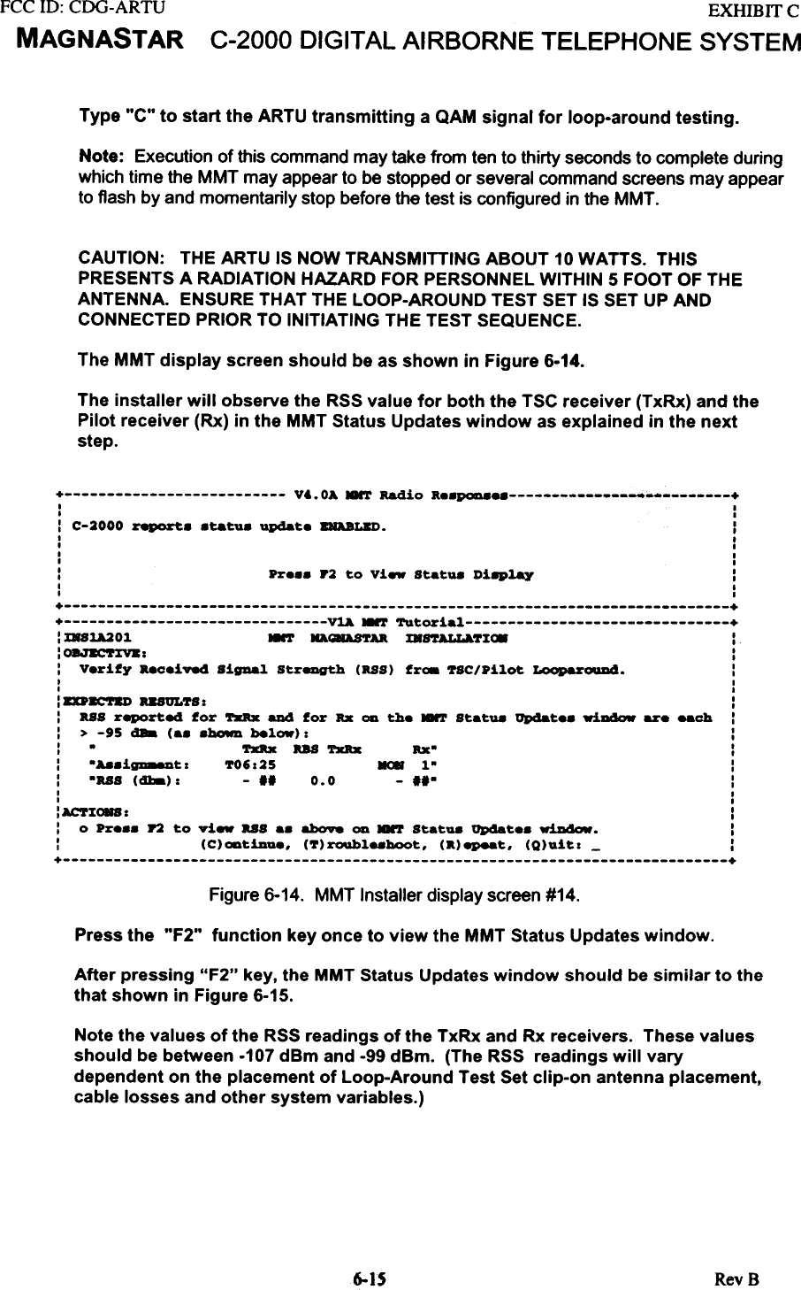
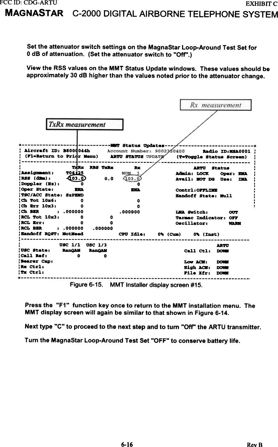
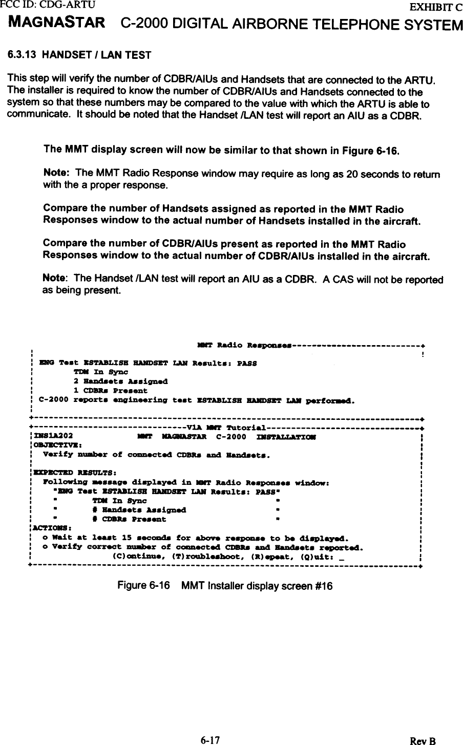
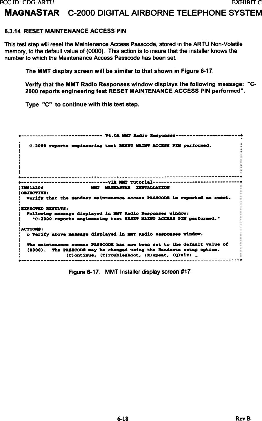
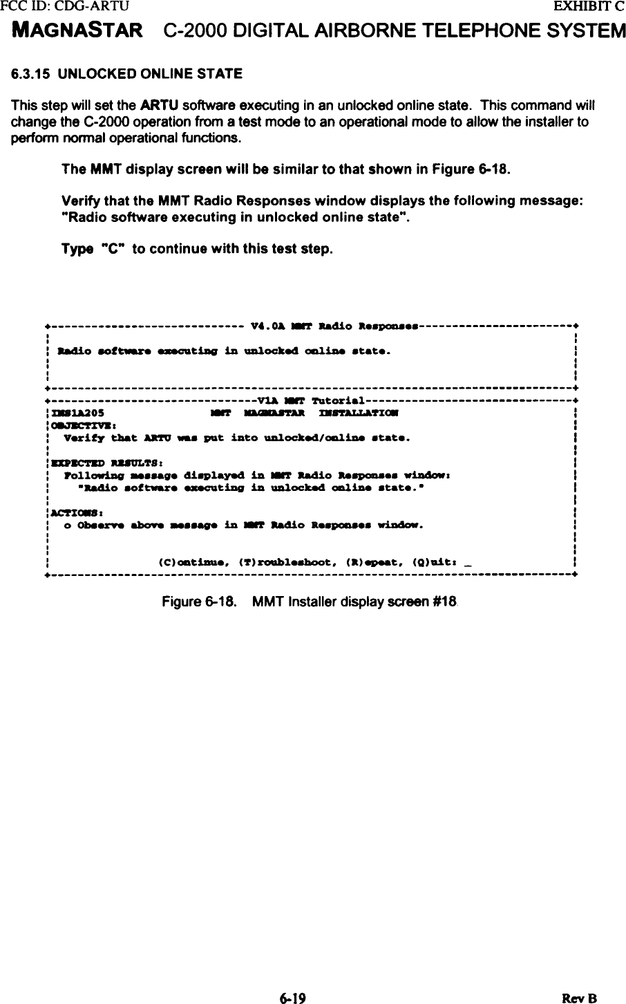
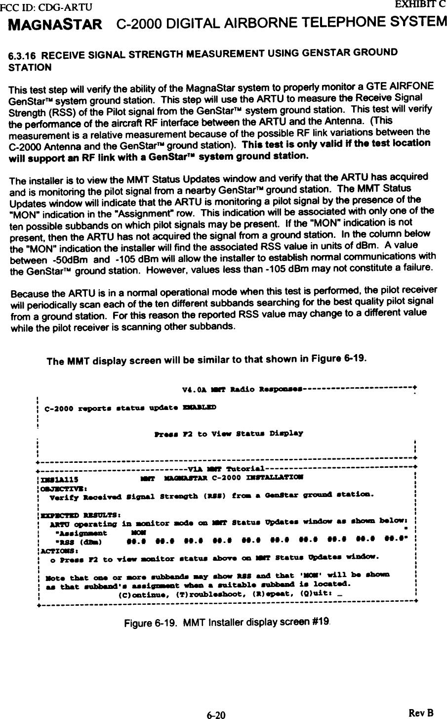
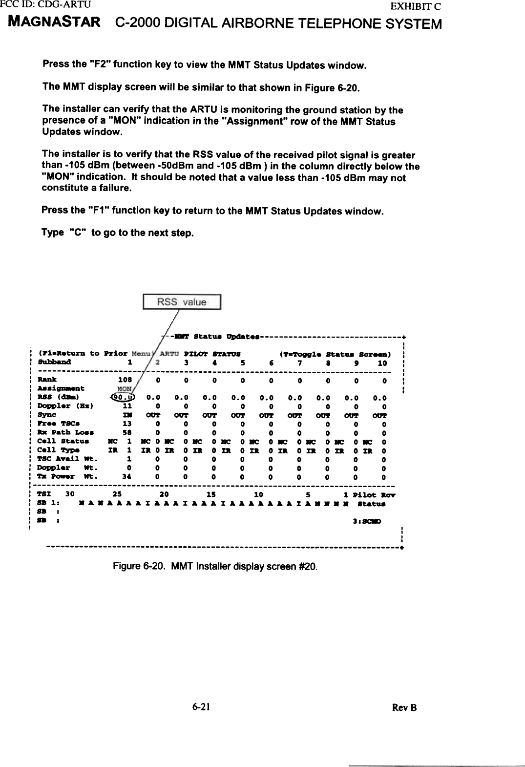
![FCC ID: CDG-ARTUMAGNASTAR EXHIB IT CC-2000 DIGITAL AIRBORNE TELEPHONE SYSTEM6.3.17 C-2000 INSTALLATION CONCLUSIONThe C-2000 Installation testing with the GTE Airfone GenStarTM Ground Station is finished at thispoint. Any further installation steps may not require MMT connection to the ARTU. If this is newinstallation, the next step is Handset Configuration (Section 7). This step concludes the MMTInstallation by having the installer enter a command to quit the MMT Installation mode.Quitting the MMTTo quit the MMT at this point. continue with the following steps:The MMT display screen will be similar to that shown in Figure 6-21.Type "Q" to quit the MMT C-2000 Installation.Note: Turn "off'the MMT computer to conserve battery power.Disconnect the MMT cable from the ARTU.Reconnect the MMT dust cover to the MMT connector.+ Vt.OA -.T Radio R..POD +I II II II II ,I ,I II II II I+ ++ VlA ~ Tutorial +: D8~]" 8'r orB C-2000 ~~ :I II I: ~. CODclude. the 8'r C-2000 XD8ta11atiOD. :I II I: To QDit the MNT, pr... '0' at thi. t!8e. :I II I: To r.-_cut. the 8'r Tutorial, pre.. 'c' at thi. t~. :I II II II II II II II I: (C)ODtiau8, (7)roQbl..boot, (a)epeat, (Q).t~1 - :+ +Figure 6-21. MMT Installer display screen #21Re-executina the MMTThe MMT tutorial may be also be re-executed at this point. If the MMT is to be re-executed,power to the ARTU must be removed for greater than ten seconds.The MMT display screen will be similar to that shown in Figure 6.21Remove power to the ARTU for greater than 20 seconds.Type "C" to re-execute the MMT C-2000 Installation.PROGRAMMING THE MAGNAST AR SYSTEM6-22 RevS](https://usermanual.wiki/Raytheon-IIS/ARTU.installation-manual-part-two/User-Guide-257060-Page-26.png)