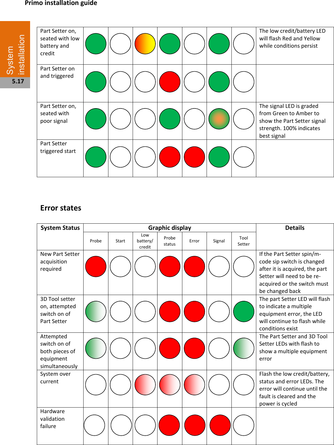
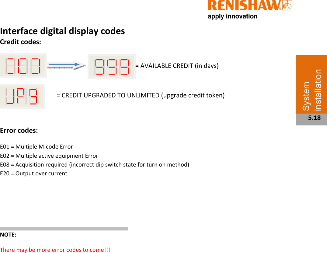
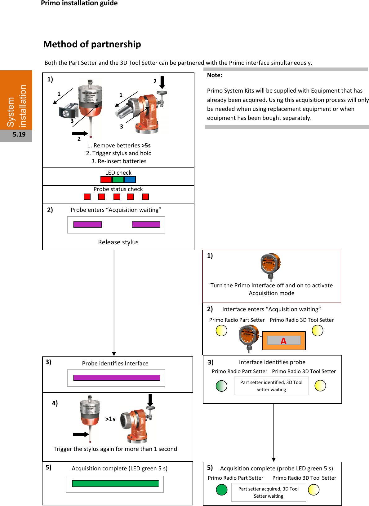
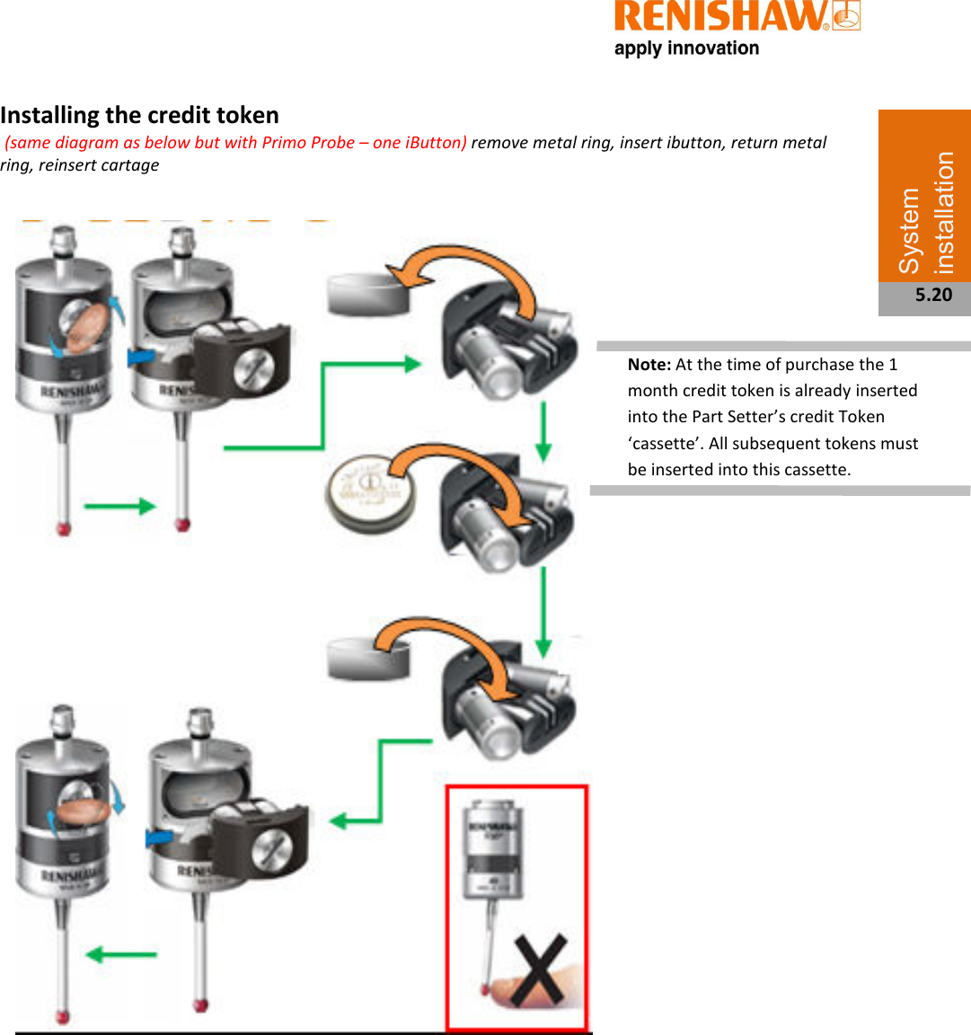
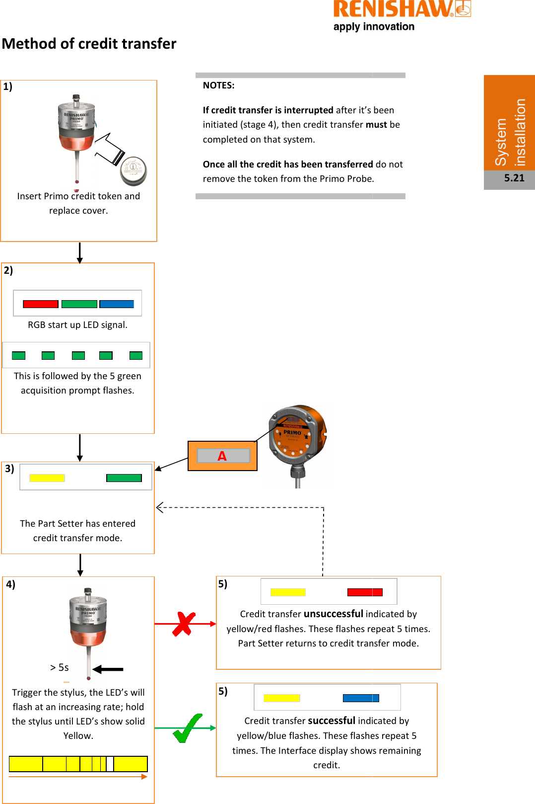
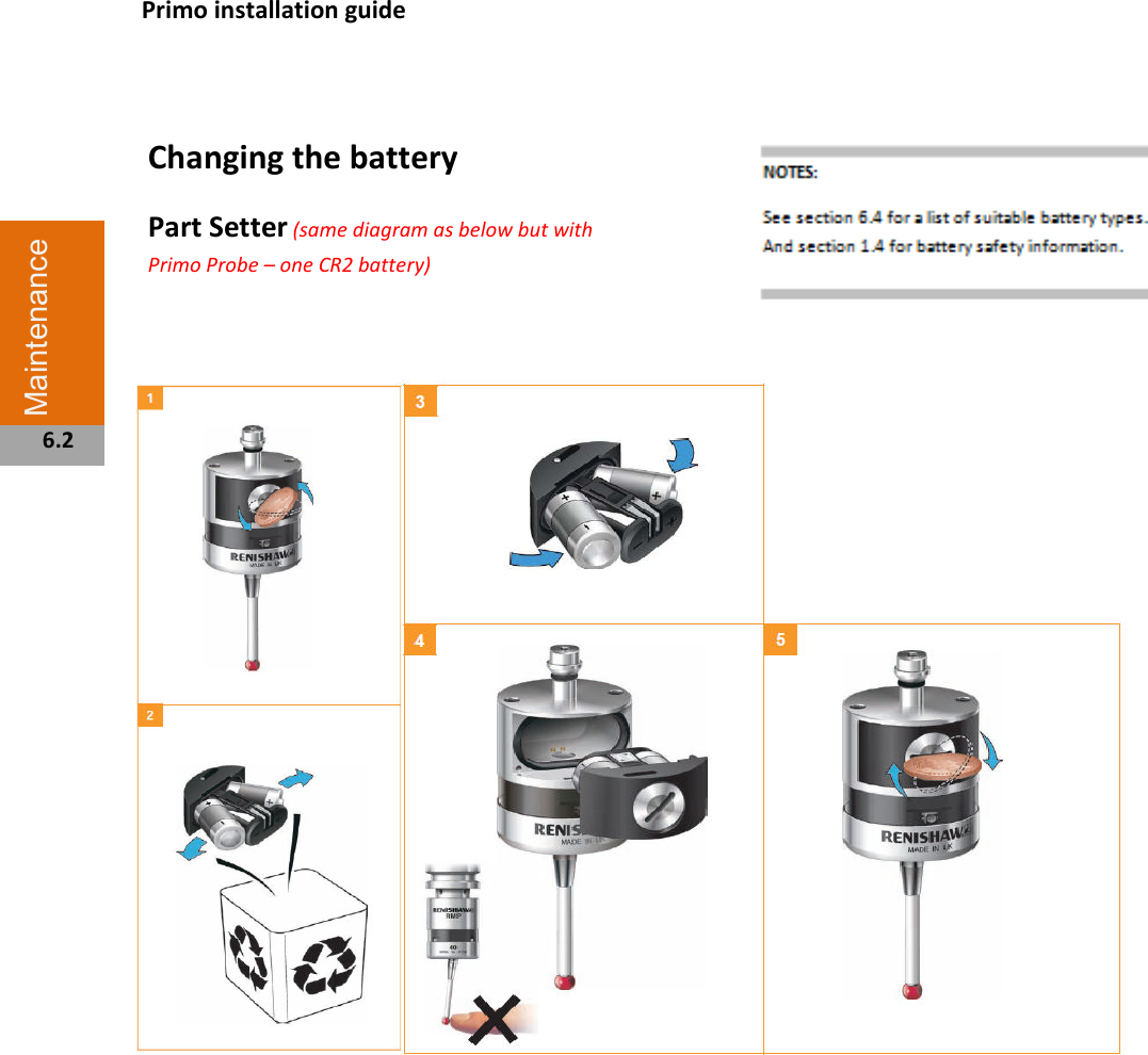
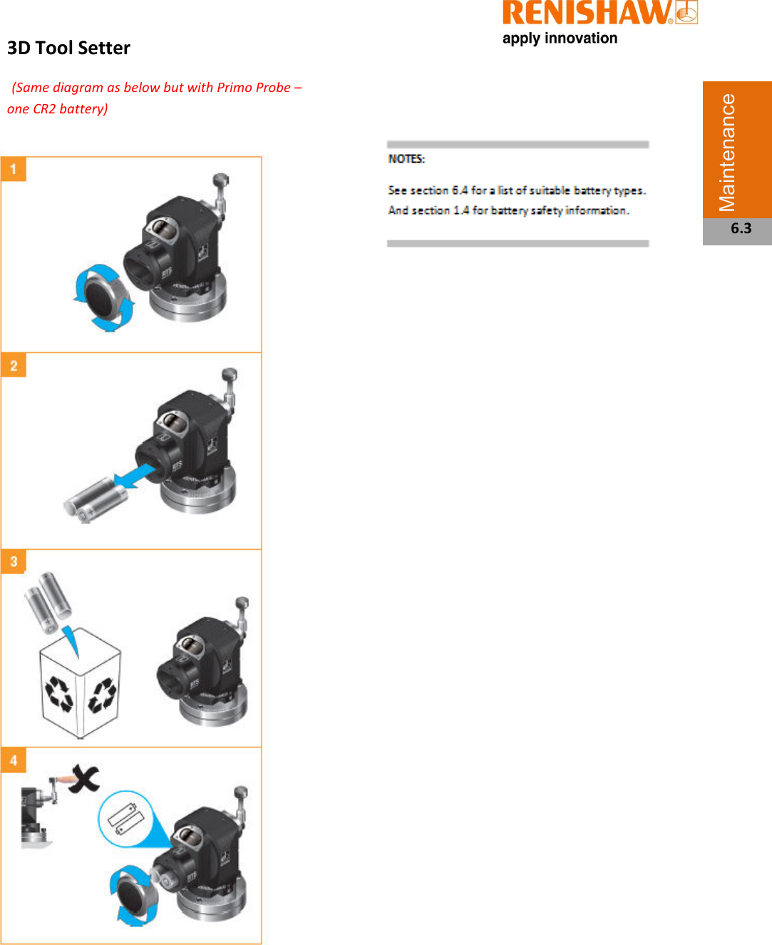
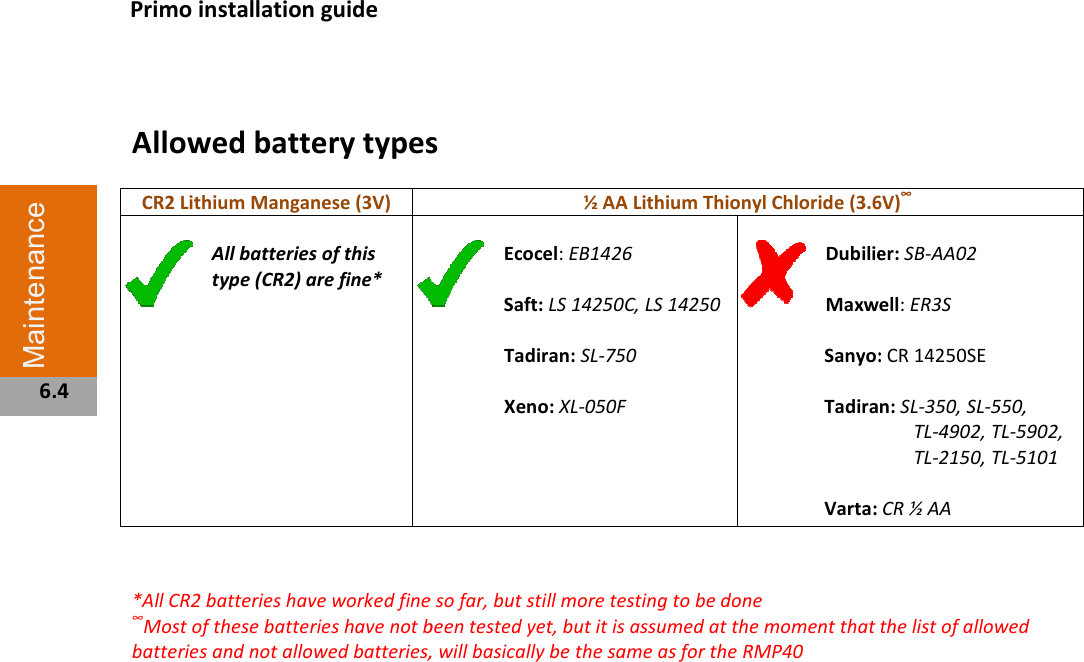
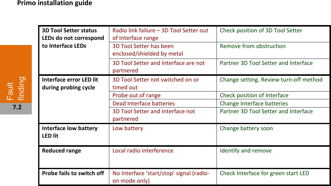
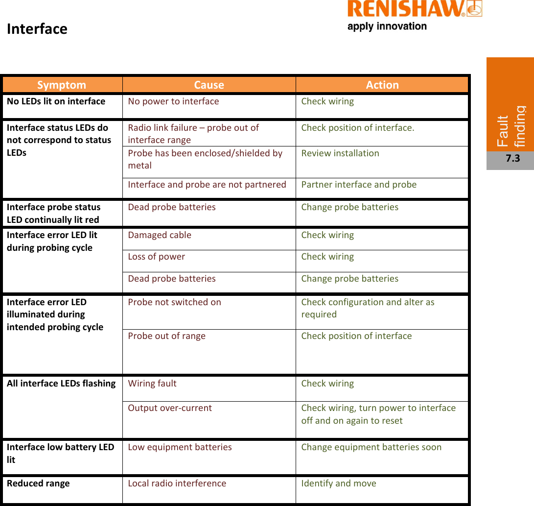
Renishaw plc PRPS Primo Radio Part Setter User Manual Primo Installation Guide Jan 2014

Renishaw plc Primo Radio Part Setter Primo Installation Guide Jan 2014

Manual

                                         Primo™ system
  © 2013 Renishaw plc. All rights reserved.  This document may not be copied or reproduced in whole or in part, or transferred to any other media or language, by any means, without the prior written permission of Renishaw plc.  The publication of material within this document does not imply freedom from the patent rights of Renishaw plc.
       Contents Before you begin......................................................................................................................... 1.1 Before you begin....................................................................................................................1.1 Disclaimer................................................................................................................. 1.1 Trademarks............................................................................................................... 1.1 Warranty................................................................................................................... 1.1 Changes to equipment.............................................................................................. 1.1 CNC machines............................................................................................................1.1 Care of the Primo equipment................................................................................... 1.1 Patents................................................................................................................................... 1.2 EC declaration of conformity................................................................................................. 1.3 WEEE directive.......................................................................................................... 1.3 FCC declaration (US)................................................................................................. 1.3 Radio approvals..................................................................................................................... 1.4 Safety..................................................................................................................................... 1.5 Information to the equipment installer................................................................................. 1.6 Primo training programme.................................................................................................... 1.7 Radio Part Setter & Radio 3D Tool Setter Basics 2.1 Introduction........................................................................................................................... 2.1 Getting started.......................................................................................................... 2.1 Credit........................................................................................................................ 2.1 Modes of operation.................................................................................................. 2.1 Configurable settings............................................................................................................. 2.2  Switch on/switch off methods.................................................................................. 2.2 Enhanced trigger filter.............................................................................................. 2.2 Recalibration............................................................................................................. 2.2 Acquisition mode...................................................................................................... 2.2 Primo credit token................................................................................................................. 2.3 Upgrade credit token................................................................................................ 2.3 Credit transfer........................................................................................................... 2.3 Four low credit indicators......................................................................................... 2.3 Radio Part Setter & Radio 3D Tool Setter operation............................................................. 2.4 Achievable set-up tolerances.................................................................................... 2.4  Software routines.................................................................................................................. 2.5 Interface basics 3.1 Introduction........................................................................................................................... 3.1   Power supply............................................................................................................ 3.1 Input voltage ripple................................................................................................... 3.1      Contents                                                                                                                                                                                                                          I
  Renikey...................................................................................................................... 3.1 Interface visual diagnostics....................................................................................... 3.1 Interface inputs...................................................................................................................... 3.2 Interface outputs................................................................................................................... 3.2 SSR output specifications.......................................................................................... 3.2 Interface output waveform.................................................................................................... 3.3 Switches SW1 and SW2.......................................................................................................... 3.4 Switch SW1 output configuration.......................................................................................... 3.5 Switch SW2 output configuration............................................................................. 3.5 Dimensions and specifications 4.1 Radio Part Setter dimensions.................................................................................................4.1 Radio 3D Radio Tool Setter dimensions................................................................................. 4.2 Interface dimensions............................................................................................................. 4.3 Radio Part Setter specification............................................................................................... 4.4 3D Radio Tool Setter specification......................................................................................... 4.5 Interface specification........................................................................................................... 4.6 System installation 5.1 Operating envelope............................................................................................................... 5.1 Signal Strength LED…………………………………………………………………………………………………………….5.1 Performance envelope........................................................................................................... 5.2 Radio Part Setter – Interface positioning.................................................................. 5.2 Performance envelope.............................................................................................. 5.2 Preparing the Radio Part Setter for use................................................................................. 5.3 Fitting the stylus..................................................................................................................... 5.3 Installing the battery.............................................................................................................. 5.4 Mounting the Radio Part Setter on a shank........................................................................... 5.5 Radio Part Setter stylus on-centre adjustment...................................................................... 5.6 Preparing the Radio 3D Tool Setter for use........................................................................... 5.7 Fitting the stylus, break stem and captive link....................................................................... 5.7 Installing the battery.............................................................................................................. 5.8 Mounting the 3D Tool Setter on a machine table............................................................... 5.9 Radio 3D Tool Setter stylus level setting.............................................................................. 5.10 Preparing the Interface for use............................................................................................ 5.11 Mounting bracket................................................................................................... 5.11 Wiring diagram.................................................................................................................... 5.12 Interface cable..................................................................................................................... 5.13                              Cable specification.................................................................................................. 5.13 Cable sealing........................................................................................................... 5.13 Fitting flexible conduit............................................................................................ 5.13 Interface screw torque values............................................................................................. 5.14 Calibrating the Primo System.............................................................................................. 5.15   Why calibrate?........................................................................................................ 5.15 Radio Part Setter LED guide................................................................................................. 5.16 Start up................................................................................................................................ 5.16 Acquisition mode................................................................................................................. 5.16 Operational mode................................................................................................................ 5.16 Errors................................................................................................................................... 5.16 Credit transfer mode (Radio Part Setter only)..................................................................... 5.16 Interface LED signals............................................................................................................ 5.17 Acquisition mode................................................................................................................. 5.17 Credit transfer...................................................................................................................... 5.17 Primo installation guide Contents ii
  Operational mode................................................................................................................ 5.17 Error states.......................................................................................................................... 5.17 Interface digital display codes............................................................................................. 5.18 Credit codes............................................................................................................ 5.18 Error codes.............................................................................................................. 5.18 Method of partnership........................................................................................................ 5.19 Inserting Primo Credit Token……………………………………………………………………………………………5.20 Method of credit transfer.................................................................................................... 5.21 Maintenance............................................................................................................................... 6.1    Maintenance.......................................................................................................................... 6.1 Cleaning.................................................................................................................... 6.1 Changing the batteries........................................................................................................... 6.2 Radio Part setter.................................................................................................................... 6.2 Radio 3D Tool Setter.............................................................................................................. 6.3 Allowed battery types............................................................................................................ 6.4 Interface cover....................................................................................................................... 6.5 Removing the Interface cover................................................................................................ 6.5 Routine Radio 3D Tool Setter maintenance........................................................................... 6.6 Inspecting the inner diaphragm seal...................................................................................... 6.6 Fault finding 7.1   Radio Part setter.................................................................................................................... 7.1 Radio 3D Tool Setter.............................................................................................................. 7.2 Interface................................................................................................................................. 7.3  Parts list 8.1  Appendix 1: Primo Radio Part Setter and Primo Length Tool Setter combination relay configurations      Contents iii
        Before you begin Disclaimer RENISHAW HAS MADE CONSIDERABLE EFFORTS TO ENSURE THE CONTENT OF THIS DOCUMENT IS CORRECT AT THE DATE OF PUBLICATION BUT MAKES NO WARRANTIES OR REPRESENTATIONS REGARDING THE CONTENT. RENISHAW EXCLUDES LIABILITY, HOWSOEVER ARISING, FOR ANY INACCURACIES IN THIS DOCUMENT.  Trademarks  RENISHAW® and the probe emblem used in the RENISHAW logo are registered trademarks of Renishaw plc in the UK and other countries. Apply innovation™ and Primo™ are trademarks of Renishaw plc. All other brand names and product names used in this document are trade names, service marks, trademarks, or registered trademarks of their respective owners.  Warranty  Equipment requiring attention under warranty must be returned to your equipment supplier. No claims will be considered where Renishaw equipment has been misused, or where repairs or adjustments have been attempted by unauthorised persons. Prior consent must be obtained in instances where Renishaw equipment is to be substituted or omitted. Failure to comply with this requirement will invalidate the warranty.      Changes to equipment  Renishaw reserves the right to change equipment specifications without notice.  CNC machines  CNC machine tools must always be operated by fully trained personnel in accordance with the manufacturer’s instructions.  Care of the Primo equipment  Keep systems clean and treat the equipment as precision tools.                        Before you begin  1.1
  Patents  Features of the Primo system, and other similar Renishaw products, are the subject of one or more of the following patents and/or patent applications:    Publication No                  CountryIPSS Ref  CN100416216     China0589/CNw/0 CN100466003     China0583/CNw/0 CN101476859     China0589/CNw/2 CN101354230     China0737/CN/0 CN101354266     China0738/CN/0 CN101482402     China0583/CNw/2 EP0695926     Europe0334/EP/ EP0967455     Europe0426/EP/ EP1185838     Europe 0466/EP/ EP1373995     Europe 0492/EP/ EP1425550     Europe 0522/EP/ EP1457786     Europe 0587/EP/ EP1477767     Europe 0466/EP/ EP1477768     Europe 0466/EP/ EP1576560     Europe 0583/EP/ EP1613921     Europe 0589/EP/ EP1701234     Europe 0492/EP/ EP1734426     Europe 0492/EP/ EP1804020     Europe 0522/EP/ EP1988439     Europe 0492/EP/ EP2018935     Europe 0737/EP/ EP2019284     Europe 0738/EP/ EP2216761     Europe 0583/EP/ IN215787     India 0583/INw/0 IN234921     India 0589/INw/0 IN8707/DELNP/2008   India 0589/INw/2 JP2009-053187                   Japan 0738/JP/0 JP2013-101685                   Japan 0583/JP/3 JP2013-137313                   Japan 0737/JP/2 JP3967592     Japan 0466/JPw/0 JP4237051     Japan 0522/JPw/0 JP4398011     Japan 0426/JP/0 JP4575781     Japan 0583/JPw/0 JP4754427     Japan 0466/JPw/2 JP4773677     Japan 0492/JPw/0 JP4851488     Japan 0492/JP/2 JP4852411     Japan 0589/JPw/0 JP5238749     Japan 0583/JP/2 JP5254692     Japan 0737/JP/0 KR1001244     Korea (South) 0583/KRw/0 TW 1380025     Taiwan 0738/TW/0 TW 200912579     Taiwan 0737/TW/0 US 2009/0028286  USA 0763/US/2              US 2011/0002361  USA 0583/US/2 US 2013/0152418  USA 0738/US/2 US 2013/0159714  USA 0737/US/2 US5669151     USA 0334/US/0 US6275053     USA 0426/US/0 US6776344     USA 0466/USw/0 US6941671     USA 0522/USw/0 US7145468     USA 0492/USw/0 US7285935     USA 0587/US/0 US7316077     USA 0589/USw/0 US7441707     USA 0466/USw/2 US7486195     USA 0492/USw/2 US7812736     USA 0492/US/3 US7821420     USA 0583/USw/0 US8437978     USA 0738/US/0 US8464054     USA 0737/US/0                            Primo installation guide Before you begin  1.2
     EC Declaration of conformity  Renishaw plc hereby declares that the Primo Radio Part Setter, Radio 3D Tool Setter and Interface are in compliance with the essential requirements and other relevant provisions of Directive 1995/5/EC. Contact Renishaw plc at www.renishaw.com for the full EC Declaration of Conformity.   WEEE directive          The use of this symbol on Renishaw products and/or accompanying documentation indicates that the product should not be mixed with general household waste upon disposal. It is the responsibility of the end user to dispose of this product at a designated collection point for waste electrical and electronic equipment (WEEE) to enable reuse or recycling. Correct disposal of this product will help to save valuable resources and prevent potential negative effects on the environment. For more information, please contact your local waste disposal service or Renishaw distributor.   Battery disposal The crossed out wheeled bin symbol on the batteries used in this product indicate that batteries must be collected and disposed of separately from household waste in accordance with EU battery directive 2006/66/EC . Please contact your local authority about the rules on the separate collection of batteries because correct disposal helps to prevent negative consequences for the environmental and human health.     FCC declaration (US)  FCC section 15.19  This device complies with Part 15 of the FCC rules. Operation is subject to the two conditions: 1. This device may not cause harmful interference. 2. This device may accept any interference received, including interference that may cause undesired operation.  FCC section 15.21  The user is cautioned that any changes or modifications not expressly approved by Renishaw plc, or an authorized representative, could void the user’s authority to operate the equipment.                     Before you begin  1.3
  Radio approvals (radio approvals needed)  Approvals that are planned to be granted for launch: • Europe (EU & EFTA) • USA • Canada • Japan • China • South Korea • India • Indonesia • Malaysia • Singapore • Taiwan • The Philippines • Vietnam • Australia • New Zealand   Radio Regulations   Extract from Taiwanese radio regulations  低功率電波輻性電機管理辦法 第十二條經型式認證合格之低功率射頻電機,非經許可,公司、商號或使用者均不 得擅自變更頻率、加大功率或變更原設計之特性及功能。 第十四條低功率射頻電機之使用不得影響飛航安全及干擾合法通信;經發現有干擾 現象時,應立即停用,並改善至無干擾時方得繼續使用。前項合法通信,指依電信 規定作業之無線電信。低功率射頻電機須忍受合法通信或工業、科學及醫療用電波 輻射性電機設備之干擾。          Radio equipment – Canadian warning statements  English "Under Industry Canada regulations, this radio transmitter may only operate using an antenna of a type and maximum (or lesser) gain approved for the transmitter by Industry Canada. To reduce potential radio interference to other users, the antenna type and its gain should be so chosen that the equivalent isotropically radiated power (e.i.r.p.) is not more than that necessary for successful communication." "This device complies with Industry Canada licence-exempt RSS standard(s). Operation is subject to the following two conditions: (1) this device may not cause interference, and (2) this device must accept any interference, including interference that may cause undesired operation of the device." Français  "Conformément à la réglementation d'Industrie Canada, le présent émetteur radio peut fonctionner avec une antenne d'un type et d'un gain maximal (ou inférieur) approuvé pour l'émetteur par Industrie Canada. Dans le but de réduire les risques de brouillage radioélectrique à l'intention des autres utilisateurs, il faut choisir le type d'antenne et son gain de sorte que la puissance isotrope rayonnée équivalente (p.i.r.e.) ne dépasse pas l'intensité nécessaire à l'établissement d'une communication satisfaisante." "Le présent appareil est conforme aux CNR d'Industrie Canada applicables aux appareils radio exempts de licence. L'exploitation est autorisée aux deux conditions suivantes: (1) l'appareil ne doit pas produire de brouillage, et (2) l'utilisateur de l'appareil doit accepter tout brouillage radioélectrique subi, même si le brouillage est susceptible d'en compromettre le fonctionnement."    Primo installation guide Before you begin  1.4
  Safety Information to the user The Primo Radio Part Setter and the Radio 3D Tool Setter are both supplied with one 3 Volt CR2 Lithium Manganese battery each. 3.6 Volt ½ AA Lithium Thionyl Chloride batteries may also be used (see section 4.2).  Lithium batteries must be approved to IEC 62133.  Please dispose of the batteries on accordance with your local environmental laws once the charge has depleted. Do not attempt to recharge these batteries. Please ensure replacement batteries are fitted in accordance with the instructions in this manual and as indicated on the product. For specific battery operating, safety and disposal guidelines please refer to the battery manufacturer’s literature.  CAUTIONS: • Do not leave dead batteries in the equipment. • Do not allow coolant or debris to enter the battery compartment. • When changing the battery check that the battery polarity is correct. • Do not store batteries in direct sunlight or rain.  • Avoid forced discharge of the batteries. • Do not short-circuit the batteries. • Do not disassemble, pierce, deform or apply excessive pressure to the batteries. • Do not swallow the batteries. • Keep the batteries out of the reach of children. • Do not get batteries wet. • If a battery is damaged, make sure to exercise caution when handling it. • Never dispose of batteries in fire.     NOTES: Always ensure that the gasket and mating surfaces are clean and free from dirt before reassembly. After removing the old battery, wait more than 5 seconds before inserting the new battery. If a dead battery is inadvertently inserted into the probe then the LEDs will remain a constant red.  Please ensure that you comply with international and national battery transport regulations when transporting batteries or the products; Lithium batteries are classified as dangerous goods and strict controls apply on their shipment by air. If you should need to return your Primo Radio Part Setter or Radio 3D Tool Setter to Renishaw for any reason, do not return any batteries to reduce shipment delays.   In all applications involving the use of machine tools eye protection is recommended.  The Primo Radio 3D Tool Setter has a glass window around it. Handle with care if broken to avoid injury.   Information to the machine supplier/installer  It is the machine supplier's responsibility to ensure that the user is made aware of any hazards involved in operation, including those mentioned in Renishaw product literature, and to ensure that adequate guards and safety interlocks are provided.   Under certain circumstances, the probe signal may falsely indicate a probe seated condition. Do not rely on the probe signals to halt the movement of the machine and always programme an over travel distance stop into the machining programme.     Before you begin  1.5
  Information to the equipment installer  All Renishaw equipment is designed to comply with the relevant EC and FCC regulatory requirements. It is the responsibility of the equipment installer to ensure that the following guidelines are adhered to, in order for the product to function in accordance with these regulations:  •  Any interface must be installed in a position away from any potential sources of electrical noise, i.e. power transformers, servo drives etc. •  All ground connections should be connected to the machine 'star point' (the 'star point' is a single point return for all equipment ground and screen cables). Failure to adhere to this can cause a potential difference between grounds. •  All screens must be connected as outlined in the user instructions. •  Cables must not be routed alongside high current sources (i.e. motor power supply cables etc), or be near high speed data lines. •  Cable lengths should always be kept to a minimum.   Equipment operation  If the equipment is used in a way not specified by the manufacturer, the protection provided by the equipment may be impaired.                          Before you begin  1.6 Primo installation guide
    Primo training programme                                              Primo installation guide The Primo system has been designed to be the ideal package for customers who are new to using metrology devices on their machine tools.  To ensure that customers achieve the best results from their purchased system Primo comes with a training package designed especially for Primo.  The Primo training programme consists of self study modules with a number of exercises in measuring a standard part that is provided with the kit. This should give all of the equipment users a high level of confidence in the equipment and their ability to use it.   Each Primo System should be supplied with a Primo Training Programme package from your Machine Tool supplier. If you have not received the Primo Training Package or any elements are missing please contact your local Renishaw office.  To find this please visit www.renisaw.comPrimo training programme                                                                The Primo system has been designed to be the ideal package for customers who are new to using metrology To ensure that customers achieve the best results from their purchased system Primo comes with a training package designed especially for Primo.  The Primo training programme consists of self study modules with a number of exercises in measuring a d part that is provided with the kit. This should give all of the equipment users a high level of confidence in the  The Primo training programme covers key routines and skills in the following areas:• Calibration • Work piece set up • Tool setting • Broken tool detectionAs you progress through the training programme more routines and training areas are unlocked. Once all of the training areas are complete each user will be sent a digital certificate to prove that completed the Primo Training Programme. Each Primo System should be supplied with a Primo from your Machine Tool supplier. If you have not received the Primo Training Package or any elements are missing please contact your sit www.renisaw.com Primo System ‘Smiley’ training work pieceBefore you begin  1.7 The Primo training programme covers key routines and skills in the following areas: Work piece set up and coordinate setting Broken tool detection As you progress through the training programme more routines and training areas are unlocked.  Once all of the training areas are complete each user will be sent a digital certificate to prove that they have completed the Primo Training Programme.  Primo System ‘Smiley’ training work piece
       Introduction When used within a system: •  The Radio Part Setter enables part setup and inspection on machining centres.  •  The Radio 3D Tool Setter enables broken tool detection and tool setting (length/diameter). Primo Radio Part Setter and Radio 3D Tool Setter; •  Deliver interference-tolerant radio transmission through the use of the FHSS (Frequency Hopping Spread Spectrum). o Allows multiple systems to work in the same machine shop without interference.  o Using radio transmission enables non line-of-sight operation.  Getting started The Primo Radio Part Setter and Radio 3D Tool Setter have LEDs to provide visual indication of their status as well as overall system status.  •  See section 5.21 for an LED guide.            Credit The Primo system requires credit to function; •  Credit is in the form of a Primo credit token.  •  This is inserted into the Radio Part Setter which then transfers the credit to the Primo Interface. Section 5.29. Modes of operation Standby mode  The equipment is waiting for a switch on signal and the Interface is waiting to send a switch on signal after receiving a signal from the machine tool. Operational mode  Activated by a switch on signal from the Interface or a Spin. The equipment is ready for use. Acquisition mode  Used to configure the partnering of the Primo Radio Part Setter and Radio 3D Tool Setter with the Interface. The acquisition method is described in section 5.28. Credit transfer mode (Radio Part Setter only) Used to transfer credit from the Radio Part Setter to the Interface. Section 5.29.        Primo Radio Part Setter and Radio 3D Tool Setter basics  2.1
   Configurable settings Radio 3D Tool Setter switch on/off  The switch on/off method for the Radio 3D Tool Setter is not user configurable. The method used is radio on/off. Enhanced trigger filter  When the filter is enabled a constant 10 ms filter delay is introduced to the equipment output.  •  It may be necessary to reduce the Radio Part Setters approach speed to allow for the increased stylus overtravel during the extended time delay.  Re-calibration  If settings are changed via the Interface switches, it is vital that the equipment is re-calibrated; See sections 5.17 – 5.20.   Acquisition mode The partnering of the Primo Radio Part Setter or Radio 3D Tool Setter and the Interface described in section 5.28.   NOTE: To enter the Interface into acquisition mode, Renikey or a power cycle will need to be used. Locate the Renikey manual before starting the partnership process.  See 3.1.  Partnering is required during initial system set up or if the Radio Part Setter turn on method had changed.  •  Partnering will not be lost by reconfiguration of the equipment settings or when changing batteries. •  Partnering can take place anywhere within the performance envelope (section 5.2).  Description  Factory setting Equipment switch on/ switch off method    Radio on/off   Commanded by machine output.     Radio on/off  Spin on/off  Spin at 1000 rpm for 1.5 s minimum. (Radio Part Setter only) Enhanced trigger filter The enhanced trigger filter improves the equipments’ resistance to triggering and triggering without contacting a surface.  Enhanced trigger filter  OFF Hibernation mode When the Primo Radio Part Setter or 3D Tool Setter are in standby and the Primo Interface is powered off or out of range, the equipment enters hibernation; a low power mode. The Part Setter or 3D Tool Setter ‘wake’ from hibernation to periodically check for their partnered Interface. The ‘wake up’ frequency is sent every 30 seconds when hibernation is activated.  Hibernation mode ON Primo installation guide The basics – probes  2.2
  Primo credit token Primo credit token contains the credit that allows the Primo probing system to function. The Primo system will not work without credit being available in the system. The standard Primo credit token contains 6 months worth of credit. Upgrade credit token Another credit token available is the Upgrade token; this allows the Primo system to work for an unlimited period. Credit transfer Credit is loaded into the Primo System by transferring Credit from the Credit token and into the Primo Interface. See section 5.29.     NOTE: How to purchase credit: A new 6 month credit token, or an Upgrade credit token can be purchased from the Primo website www.primoprobing.com. You can also contact your local Renishaw supplier. See www.renishaw.com/contact. Installation: Please ensure that the Primo Credit Token is installed in the Radio Part Setter in the orientation shown with the lip of the Token inboard. Failing to do this will result in the Credit not being transferred. Four low credit indicators 1.  Equipment LEDs      2.  Interface low battery/credit LED      3.  Interface digital display (123 days remaining shown). When the remaining credit display reads 0 days then the Primo System will stop working and new credit will need to be loaded into the system.     4.  Low battery/credit output from the Interface, which can be connected to the machine control. When credit is running low, an alarm will be sent to the control.   When any of these low credit indicators are shown it is recommended that a new Primo Credit Token is loaded into the system. Primo installation guide Constant Flashing The basics – probes  2.3
  Primo Radio Part Setter operation  The Primo Radio Part Setter operates as a highly accurate and repeatable mechanical switch that triggers as the stylus deflects against a surface.  •  The Radio Part Setter can measure in the X, Y and Z axis.  •  The Primo Radio Part Setter can be used for work co-ordinate setting and for work piece measurement. •  A trigger signal is sent directly to the CNC controller so that offsets can be updated – no manual intervention is required.                Primo Radio 3D Tool Setter operation  The Radio 3D Tool Setter enables accurate machining by measuring the length and diameter of tools using the same highly accurate and repeatable switch mechanism has the Primo Radio Part Setter. •  The tool is set in the Z axis for tool length measurement and broken tool detection. •  Rotating tools are set in the X and Y axes for tool radius measurement.          The basics – probes  2.4
  Software routines  Primo Software caters for 3-axis applications and covers basic probing routines. •  Calibration •  Tool setting •  Broken tool detection  •  Work piece set-up •  Work piece measurement  For further information refer to the Primo Software Programming Guide H – 54XXXX  NOTES: Software routines for tool setting are available from Renishaw and are described in data sheet H-2000-2289, which can be found at www.renishaw.com. Software upgrades - Purchase an upgrade to the Inspection+ and Five Face Tool Setting package, as well as the Productivity+ package. See www.renishaw.com                                             The basics – probes  2.5 Primo installation guide
       Introduction The Primo Interface enables communication between the Machine Tool, Radio Part Setter and the Radio 3D Tool Setter using radio frequencies. Power supply  The Interface requires a 12 Vdc to 30 Vdc supply capable of supplying 150 mA minimum (TBC). Input voltage ripple  The input voltage ripple must not cause the voltage to fall below 12 V or go above 30 V. ReniKey Renikey is a Renishaw machine programme which is used while partnering the equipment with the Interface. Refer to the ReniKey programming manual for instructions on how to use ReniKey or refer to www.renishaw.com.           Interface visual diagnostics              Primo Interface basics  3.1 Digital ‘remaining credit’ display and Error code display Note: If the Primo System is using a Primo Upgrade Credit Token and the Primo Interface is returned to Renishaw then the Primo Upgrade Credit Token must be returned with the interface for identification purposes.
  Interface inputs Machine start inputs: ‘Machine start’ is configurable as a level or pulsed signal. Level 12 to 30 Vdc  When input is active probe is switched on. Pulsed 12 to 30 Vdc  Part Setter toggles from being switched on/off. Minimum pulse width is 10 ms.  See section 5.14 for the full wiring diagram. Interface outputs There are four SSR outputs:  •  Probe status 1  •  Probe status 2  •  Error  •  Low battery/credit  All outputs can be inverted by using switches SW1 and SW2 (see section 3.5 for more info). SSR outputs specifications: •  Maximum ‘on’ resistance = 25 ohm  •  Maximum load voltage = 30 V  •  Maximum load current = 100 mA                               Primo installation guide The basics - Interface  3.2 Note: The term ‘Probe Status’ refers to the measurement hardware in the system interacting with the interface and can therefore refer to the Primo Radio Part Setter and the Primo Radio 3D Tool Setter.
  Interface output waveform   Signal delays: 1.   Transmission delay  Probe trigger to output change of state = 10 ms ± 10 µs without enhanced trigger filter 2.   Start delay    Time from initiation to start of signal to valid signal transmission = 1 s max   The basics - Interface  3.3 Primo Interface  /credit Probe status 2 (pulsed) Probe status 2 (level) SSR open SSR closed SSR open SSR closed
    Switches SW1 and SW2 PCB diagram like below for Primo                                      Primo installation guide The basics - Interface  3.4
  Switch SW1 output configuration  Switch SW2 output configuration              N/O N/C  Spin M-code START  On Off ENHANCED TRIGGER FILTER  Enabled Disabled HIBERNATION MODE LOW BATTERY/CREDIT The basics - Interface  3.5 Disabled Enabled Note:  If an error code E08 appears on the Primo Interface Credit remaining/error code display when a switch setting has been changed the Primo Radio Part Setter or Primo Radio 3D Tool Setter must be re-acquired.
         Part Setter dimensions                              Dimensions and specifications  4.1    61.25 (2.41) Battery cover Primo credit token cover Ø51 (2.00) 21 (0.83) 29.4 (1.16) Ø48.5 (1.91)  Primo  Primo
  3D Tool Setter dimensions                            Primo installation guide Dimensions & Specs  4.2     Ø? 44.551 (1.75) 68.75 (2.70) 93 (3.66)  55 (2.17) ? ? ?                         ? 25mm  (Ø 0.98 in x 0.16)  X 4mm 4 (0.16) Ø25 (Ø0.09)  Primo Ensure this shows the new, larger disk stylus
  Interface dimensions                               Dimensions & Specs  4.3       ?                                                40.25 (1.58)       84 (3.31)       40 (1.57)  Primo       40 (1.57)       42.1 (1.66)       43.5 (1.71)       42.1 (2.66)       15 (0.59)
  Radio Part Setter SpecificationPrinciple Application  Work piece inspection and job set-up on all sizes of machining centres Dimensions Length Diameter  61.25 mm (2.41 in) 51 mm (2.00 in) Weight (no shank) With battery and iButton Without battery  360 g 349 g Transmission Type  Frequency Hopping Spread Spectrum (FHSS) Radio Radio Frequency  2400 MHz to 2483.5 MHz Switch-on Methods  Radio M Code, Spin Switch-off Methods  Radio M Code, Spin Spindle Speed (max)  1000 rpm not yet been tested Operating Range  Transmission range 10 m Receiver/Interface  Primo Interface - combined antenna, interface and receiver unit Sense Directions  Omni-directional ±X, ±Y, +Z Uni-directional Repeatability Maximum 2σ value in any direction 1.0 µm (0.00004 in) tested with 50mm stylus. Stylus Trigger Force XY Low Force XY High Force Z  0.5 N, 50 gf (1.76 ozf) 0.9 N, 90 gf (3.17 ozf)  5.85 N, 585 gf (20.63 ozf) The stylus trigger force is the force exerted on the component when the probe triggers. However, the maximum force applied to the component will occur after the trigger point and will be greater than the trigger force. The magnitude depends on a number of factors affecting probe overtravel including measuring speed and machine deceleration. If the forces applied to the component are critical, contact Renishaw for further information. Stylus Overtravel  XY Plane +Z Plane  ±12.5˚ 6 mm (0.24 in) Environment (As defined in  BS EN 61010-1:2001) IP rating  IPX8 (BS5490, IEC 60529) 1 atmosphere Storage temperature  -25 ˚C to +70 ˚C (-13 ˚F to +158 ˚F) Operating temperature  +5 ˚C to +55 ˚C (+41 ˚F to +122 ˚F) Battery Types  1 x 3V CR2 Lithium Manganese Dioxide or 1 x 3.6V ½ AA Lithium Thionyl Chloride (see section 6.4 for further details) Battery Reserve Life  Approximately one week after a low battery warning is first given Low Battery Indication  Flashing blue LED whilst probe is seated (not triggered) Dead Battery Indication  Continuous red LED Typical Battery Life  See table below Low credit indication  Flashing yellow LED (probe seated) 21 days before credit expires No credit indication  Continuous yellow LED Battery Type Spin switch-on  Radio switch-on  Continuous use Standby life 5% usage           (72 mins/day) Standby life  5% usage CR2 Lithium Manganese Dioxide Part of alpha tests Part of alpha tests Part of alpha tests Part of alpha tests Part of alpha tests ½ AA Lithium Thionyl Chloride Part of alpha tests Part of alpha tests Part of alpha tests Part of alpha tests Part of alpha tests Primo installation guide Dimensions & Specs  4.4
  3D Tool Setter Specifications    Principal Application  Tool setting and broken tool detection on all sizes of machining centres Dimensions  Diameter  115.1 mm (4.53 in) Height with disc stylus  101.75 mm (4.01 in) Weight (without stylus) With battery Without battery  610 g (21.5 oz) 599 g (21.1 oz) Transmission Type  Frequency Hopping Spread Spectrum (FHSS) Radio Radio Frequency  2400 MHz to 2483.5 MHz Switch-on Methods  Radio M Code Switch-off Methods  Radio M Code Operating range  Transmission range 10 m Receiver/Interface  Primo Interface - combined antenna, interface and receiver unit Sense Directions  Omni-directional ±X,±Y, ±Z Uni-directional Repeatability Maximum 2σ value in any direction 1.0 µm (0.00004 in) Stylus Trigger Force  1.3 N to 2.4 N/130 gf to 240 gf (4.5 ozf to 8.5 ozf) depending on sense direction Stylus Overtravel  XY Plane  ± 3.5 mm (0.14 in) +Z Plane  5.5 mm (0.22 in) Environment   IP Rating  IPX8 (EN/IEC60529) Storage temperature  -25 ˚C to +70 ˚C (-13 ˚F to +158 ˚F) Operating temperature   +5 ˚C to +55 ˚C (+41 ˚F to +122 ˚F) Battery Types  1 x 3V CR2 Lithium Manganese Dioxide or 1 x 3.6V ½ AA Lithium Thionyl Chloride (see section 6.4 for further details) Battery Reserve Life  Approximately one week after a low battery warning is first given Typical Battery Life  See table below Low Battery Indication  Flashing blue LED (probe seated) Dead Battery Indication  Continuous red LED Low credit indication  Flashing yellow LED (probe seated) 21 days before credit expires No credit indication  Continuous yellow LED Battery Type Turn-on Time  Standby Life  5% Usage  (72 minutes/day) Continuous use CR2 Lithium Manganese Dioxide Part of alpha tests  Part of alpha tests Part of alpha tests Part of alpha tests ½ AA Lithium Thionyl Chloride Part of alpha tests Part of alpha tests Part of alpha tests Part of alpha tests Dimensions & Specs  4.5
  Interface specification            Principal application  The Interface  communicates  between  the  Machine  Tool,  the Radio  Part  Setter and the Radio 3D Tool Setter Dimensions Height Width Depth 110 mm (4.33 in) 84 mm (3.31 in) 40.25 mm (1.58 in) Weight In box Interface including 8 m (26.2 ft) of cable TBC g TBC g Transmission type Frequency hopping spread spectrum (FHSS) radio 2400 MHz to 2483.5 MHz Transmission range Transmission range 10 m Power supply 10 Vdc to 30 Vdc Cable 8 m (26.25 ft) standard length Mounting A mounting bracket can be purchased as an optional extra. See section 5.13 to find out how to install the mounting bracket with your interface. Conduit  A  flexible  conduit  to  aid  protection  of  the  Interface  cable  can  be  purchased  as  an optional  extra.  See  section  5.15  for  recommended  conduits  and  installation information. Environment IP rating  IPX8 Storage temperature  -10 ˚C to +70 ˚C (14 ˚F to 158 ˚F) Operating temperature  5 ˚C to 50 ˚C (41 ˚F to 122 ˚F) Dimensions & Specs  4.6 Primo installation guide
     Does this diagram need updating? Operating envelope Radio transmission does not require line-of-sight and will pass through small gaps and machine tool windows, providing a reflected path (of less than 10 m (49.2 ft)) is available.                   To ensure unrestricted transmission performance: Keep all Primo System components within the performance envelope (section 5.2). Ensure the Interface signal LED stays close to green. Green represents excellent signal, yellow represents reduced signal (section 5.28). Do not allow coolant and swarf residue to accumulate on the equipment.  Regularly wipe clean the Part Setter Body and the 3D Tool Setter window. Reduction in transmission range may result when operating in temperatures 0 ˚C to +5 ˚C (+32 ˚F to +41 ˚F) and +55 ˚C to +60 ˚C (+122 ˚F to +140 ˚F). Avoid these temperature ranges if possible. Signal strength LED  The signal LED on the Primo Interface indicates the number of missed communications with the equipment. The LED shows with Green to Amber the number of missed communications. When communication fails the LED goes out. The system will continue to perform 100% effectively as long as there is signal.      System installation  5.1 PRIMO Primo Radio Part Setter Primo Radio 3D Tool Setter 0% missed  100% 50%
  Equipment – Interface positioning The system elements should be positioned so that:  •  The optimum range can be achieved over the full travel of the machine’s axes.  •  The front cover of the Interface is facing in the general direction of the machining area.  Performance envelope                                                   System installation  5.2  Performance envelope for Primo Radio Part Setter Performance envelope/range will be tested in alpha testing  Diagram here  Performance envelope for 3D Tool Setter Performance envelope/range will be tested in alpha testing  Diagram here
  Preparing the Part Setter  Fitting the stylus For the most accurate results from your Primo Radio Part Setter it is crucial that a Renishaw manufactured Stylus is fitted.  (Same diagram as below but with Primo Probe)                                                          System installation  5.3
    Installing the battery (same diagram as below but with Primo Probe – one battery)       NOTES:  See Section 6.4 for a list of suitable batteries and section 1.4 for battery safety information.    System installation  5.4 Primo installation guide
  Mounting the Part Setter on a shank (same diagram as below but with Primo Probe)                                                                      System installation  5.5 Primo installation guide
  Part Setter stylus on-centre adjustment (same diagram as below but with Primo Probe) For the centre setting software view the Primo Programming guide          NOTES: If a Part Setter and shank assembly is dropped, it must be rechecked for correct on-centre adjustment. Do not hit the Part Setter to achieve on-centre adjustment. System installation  5.6
  Preparing the 3D Tool Setter for use Fitting the stylus, break stem and captive link (same diagram as below but with Primo Tool Setter and showing compartment in the back for spare break stem)     Stylus weak link break stem Incorporated into the stylus, the break stem protects the mechanism from damage in the event of excessive stylus over travel or a collision. There is a compartment in the back of the 3D Tool Setter for a spare break stem to be stored.  Captive link In the event of the break stem being damaged the captive link ties the stylus to the probe. NOTE: Always hold the support bar in the position to avoid over stressing the break stem.                 System installation  5.7 Primo installation guide
  Installing the battery (same diagram as below but with Primo Tool Setter – one battery)        NOTES: See section 6.4 for a list of suitable battery types. And section 1.4 for battery safety information.                          System installation  5.8
   Mounting the 3D Tool Setter on a machine table (same diagram as below but with Primo Tool Setter)                     1) Undo 3 of the 4 screws that hold the 3D Tool Setter to the base. 2) Bolt the 3D Tool Setter base to the table using an M12 or M10 cap head screw and washer.  (not supplied) 3) Reattach the tool setter to the base.             System installation  5.9 Primo installation guide
   3D Tool Setter stylus level setting (The same diagram but for the Primo Tool setter) For the level setting software view the Primo Programming guide Side to side level adjustment  The top surface of the stylus must be set level.  •  Alternately adjust the grub screws provided this causes the 3D Tool Setter to rotate and change the stylus level setting.  •  When the stylus surface is level, tighten the grub screws.                             System installation  5.10
   For the level setting software view the Primo Programming guide Front to back level adjustment To raise the front: Slacken locking screw 2 and adjust height adjusting screw 1 until the stylus is level. Then fully tighten screw 2.  To lower the front: Keep tightening/slackening the height adjusting screw 1 and loosening/locking screw 2 until the stylus is level. Then fully tighten screw 2.                            System installation  5.10 Primo installation guide
  Preparing the Interface for use Mounting bracket (optional) Diagram like below but for Primo.                                 System installation  5.11
  Interface wiring diagram                   CAUTION: The power supply 0 V should be terminated at the machine ground (star point).                       Primo installation guide System installation  5.12
  Interface cable    A ferrule should be crimped onto each cable wire for a more positive connection at the terminal box. A cable sealing gland prevents coolant and dirt from entering the Interface.  The Interface cable can be further protected by a flexible conduit.  Fitting flexible conduit The recommended flexible conduit is AnametTM Sealtite HFX (5/16 in) Polyurethane. 1. Slide nut B and plastic olive onto the Conduit. 2. Screw conduit termination piece into end of the conduit. 3. Fit conduit to adaptor A and tighten nut B.            Cable specification   Length Diameter Number of cores Dimensions of each core  8 m (26.25 ft)*  7.5 mm (0.29 in)  13 cores  18 x 0.1 mm            CAUTIONS: Failure to protect the cable can result in system failure due to either cable damage or coolant ingress through cores into the Interface. Failure due to inadequate cable protection will invalidate the warranty.  System installation  5.13
  Interface screw torque values For Primo, this diagram will look like the RMI for the front cover screws and conduit adaptor, but will look like the OMI-2T for the screws at the sides of the Interface attaching it the mounting bracket. (See both diagrams below).                              Primo installation guide System installation  5.14
  Calibrating the Primo equipment  Why calibrate?  The Primo system has a built in software routine. This calibration process is described in section 5.18.  Before the equipment is used it is very important that the Radio Part Setter and 3D Tool Setter are calibrated correctly.   Calibration of the equipment allows software to compensate for possible errors in the measurements.  •  This can be caused by the difference between the position that the stylus touches and the position reported to the machine.   Calibrate:  •  when a Primo system is to be used for the first time •  at regular intervals as maintenance •  when a new stylus is fitted to the probe •  when the stylus has become distorted or the equipment has crashed •  when equipment settings are changed •  If repeatability of relocation of the probe shank is poor o  In this case, the probe may need to be recalibrated each time it is selected  Traditional calibration methods should still be used when:  •  when using a non standard stylus; •  when only one piece of equipment  is installed in the machine; •  when high accuracy is required (<10 µm); •  When working in a 4 or 5 axis machine.  The Primo System Calibration Software routines and Traditional Calibration methods are described in the Primo Programming Guide.                  System installation  5.15
  Radio Part Setter and Radio 3D Tool Setter LED Guide          = quick flash            (32 ms, 992 ms between each flash)  = quick double flash   (32 ms flash, 128 ms separating the double flash, 832 ms between each double    flash)     = flash       (128 ms, 640 ms between each flash)  = long flash   (512 ms, 512ms between each flash in acquisition mode, 128 ms between each flash in credit transfer mode, 16 ms between each flash in the RGB start up signal)  Start up   LED colour Status Graphic hint Red, Green, Blue   Equipment starting up/newly changed battery/ newly inserted credit token   Acquisition mode  LED colour Status Graphic hint 5 green flashes   Acquisition prompt (seated)   5 red flashes   Acquisition prompt (triggered)   Flashing violet  Acquisition waiting   Continuous violet  Interface identified   On green for 5 s  Acquisition complete             System installation  5.16
  Operational mode (all signals repeat)  LED colour Status Graphic hint Flashing green   Equipment seated – good battery, good credit  Flashing red   Equipment triggered *  Flashing blue   Equipment seated – low battery, good credit  Flashing yellow   Equipment seated – good battery, low credit  Flashing blue & yellow   Equipment seated – low battery, low credit  Double flashing yellow  Equipment seated – very low credit    *Probe triggered flashing red signal overrides any other indication such as low battery or credit. The status of these indicators can only be viewed when the probe is seated.  Errors  LED colour Status Graphic hint Continuous violet  Tampered hardware  Continuous red Battery dead  Continuous yellow Credit exhausted    Credit transfer mode (Primo Radio Part Setter only)  LED colour Status Graphic hint Flashing yellow and green   Credit transfer mode (repeats until mode change)  Flashing yellow and red   Credit transfer unsuccessful (repeats 5 times)  Flashing yellow and blue   Credit transfer successful (repeats 5 times)  Flashing red and violet   Credit transfer mode – represents a lifetime system   System installation  5.16 Primo installation guide
  Interface LED signals Key:                                           = LED flashing red and yellow with even periods = LED constant green = LED flashing green/off = LED graded between green and amber System installation  5.17       Radio Part Setter Probe status Radio 3D Tool Setter Start Low battery/credit Signal Error
  Acquisition mode     System Status Graphic display Details Part Setter  Start Low battery/ credit Probe status  Error  Signal  3D Tool Setter Interface in “Acquisition waiting” state        The Part Setter LEDs flash yellow/off at least once for up to 8s or until a Part Setter is discovered Interface identifies Part Setter*        The Part Setter LED flashes green for up to 3 minutes or until an “acquisition ready” message is received from the Part Setter Interface identifies 3D Tool Setter        The 3D Tool Setter LED flashes green for up to 3 minutes or until an “acquisition ready” message is received from the 3D Tool Setter Part Setter and 3D Tool Setter identified        Both LEDs flash green for up to three minutes or until an “acquisition ready” message is received from the equipment The Part Setter is acquired (3D Tool setter acquisition pending)        The part Setter LED is on, 3D Tool Setter LED flashes for 3 minutes or until the 3D Tool Setter is acquired 3D Tool Setter acquired (Part Setter acquisition pending)        The 3D Tool Setter LED is on, the Part Setter LED flashes for 3 minutes or until the Part Setter is acquired.  Part Setter acquired        Part Setter LED stays on for 5 sec 3D Tool Setter acquired        3D Tool setter LED stays on for 5 sec Part Setter and 3D Tool Setter acquired        Part Setter and 3D Tool Setter LEDs stay on for 5 sec Primo installation guide System installation  5.17
   Credit transfer  System Status Graphic display Details Part Setter  Start Low battery/ credit Probe status  Error  Signal  3D Tool Setter Credit transfer in progress        The low credit/low battery LED will flash yellow for 2s to show credit transfer in progress    Operational mode  System Status Graphic display Details Part Setter  Start Low battery/ credit Probe status  Error  Signal  3D Tool Setter Standby        Primo System in standby mode Start signal        When set to level start, the start LED will stay yellow until the Part Setter or 3D Tool Setter starts. When set to pulsed start, the start LED will stay yellow for 30s or until the equipment starts.  Standby low credit        When no equipment is operating the low credit/battery LED will be yellow if credit is low Part Setter  on and seated         Part Setter on, seated with low credit         Part Setter on, seated with low battery         System installation  5.17
     Error states  System Status Graphic display Details Probe  Start Low battery/ credit Probe status  Error  Signal  Tool Setter New Part Setter acquisition required        If the Part Setter spin/m-code sip switch is changed after it is acquired, the part Setter will need to be re-acquired or the switch must be changed back 3D Tool setter on, attempted switch on of Part Setter        The part Setter LED will flash to indicate a multiple equipment error, the LED will continue to flash while conditions exist Attempted switch on of both pieces of equipment  simultaneously        The Part Setter and 3D Tool Setter LEDs with flash to show a multiple equipment error System over current        Flash the low credit/battery, status and error LEDs. The error will continue until the fault is cleared and the power is cycled Hardware validation failure         Part Setter on, seated with low battery and credit        The low credit/battery LED will flash Red and Yellow while conditions persist Part Setter on and triggered         Part Setter on, seated with poor signal        The signal LED is graded from Green to Amber to show the Part Setter signal strength. 100% indicates best signal Part Setter triggered start         Primo installation guide System installation  5.17
  Interface digital display codes Credit codes:     Error codes: E01 = Multiple M-code Error E02 = Multiple active equipment Error E08 = Acquisition required (incorrect dip switch state for turn on method) E20 = Output over current    NOTE: There may be more error codes to come!!!               System installation  5.18 = CREDIT UPGRADED TO UNLIMITED (upgrade credit token)   = AVAILABLE CREDIT (in days)
  Interface enters “Acquisition waiting”      Interface identifies probe         Acquisition complete (probe LED green 5 s)   Method of partnership   Both the Part Setter and the 3D Tool Setter can be partnered with the Primo interface simultaneously.                                                       Turn the Primo Interface off and on to activate Acquisition mode    Trigger the stylus again for more than 1 second Primo installation guide 1) 1) Probe enters “Acquisition waiting”   Release stylus   Probe identifies Interface          Acquisition complete (LED green 5 s)       3) 3) 4) 5) 5) >1s   1. Remove betteries >5s 2. Trigger stylus and hold 3. Re-insert batteries System installation  5.19 Note: Primo System Kits will be supplied with Equipment that has already been acquired. Using this acquisition process will only be needed when using replacement equipment or when equipment has been bought separately.  2) 2) Primo Radio Part Setter Primo Radio 3D Tool Setter Primo Radio Part Setter Primo Radio Part Setter Primo Radio 3D Tool Setter Primo Radio 3D Tool Setter Part setter identified, 3D Tool Setter waiting Part setter acquired, 3D Tool Setter waiting 1 2 3 1 2 3 A Probe status check LED check
    Installing the credit token  (same diagram as below but with Primo Probe – one iButton) remove metal ring, insert ibutton, return metal ring, reinsert cartage                                    Note: At the time of purchase the 1 month credit token is already inserted into the Part Setter’s credit Token ‘cassette’. All subsequent tokens must be inserted into this cassette.  System installation  5.20
      Trigger the stylus, the LED’s will flash at an increasing rate; hold the stylus until LED’s show solid Yellow.  Method of credit transfer                              Insert Primo credit token and replace cover.   RGB start up LED signal.  This is followed by the 5 green acquisition prompt flashes.      1) 2)   The Part Setter has entered credit transfer mode.   3) > 5s 4) Method of credit transfer         Credit transfer successful indicated by yellow/blue flashes. These flashes repeat 5 times. The Interface display showscredit.  Credit transfer unsuccessful indicated byyellow/red flashes. These flashes repeat 5 times. Part Setter returns to credit transfer mode. 5) 5)  NOTES: If credit transfer is interrupted after it’s been initiated (stage 4), then credit transfer must completed on that system.  Once all the credit has been transferred remove the token from the Primo Probe. A indicated by yellow/blue flashes. These flashes repeat 5 Interface display shows remaining indicated by yellow/red flashes. These flashes repeat 5 times. to credit transfer mode.   System installation  5.21 after it’s been must be Once all the credit has been transferred do not .
         Maintenance   You may undertake the maintenance routines described in these instructions; further dismantling and repair of Renishaw equipment must be carried out by an authorised Renishaw Services Centre.  Cleaning the equipment  Wipe the window of the Radio 3D Tool Setter and the body shell of the Radio Part Setter with a clean cloth on a regular basis to remove machining residue.                               Maintenance   6.1
  Changing the battery Part Setter (same diagram as below but with Primo Probe – one CR2 battery)                           Maintenance  6.2 Primo installation guide
  3D Tool Setter  (Same diagram as below but with Primo Probe – one CR2 battery)                                                 Maintenance  6.3
  Allowed battery types CR2 Lithium Manganese (3V)  All batteries of this type (CR2) are fine*                                            *All CR2 batteries have worked fine so far, but still more testing to be done∞Most of these batteries have not been tested yet, but it is assumed at the moment that thebatteries and not allowed batteries, will basically be the same as for the RMP40            Maintenance  6.4 Primo installation guide Allowed battery types ½ AA Lithium Thionyl Chloride (3.6V) Ecocel: EB1426  Saft: LS 14250C, LS 14250                   Tadiran: SL-750                   Xeno: XL-050F    Dubilier: Maxwell                 Sanyo:                 Tadiran:                                                                                       Varta: *All CR2 batteries have worked fine so far, but still more testing to be done Most of these batteries have not been tested yet, but it is assumed at the moment that thebatteries and not allowed batteries, will basically be the same as for the RMP40             AA Lithium Thionyl Chloride (3.6V)∞ Dubilier: SB-AA02 Maxwell: ER3S Sanyo: CR 14250SE Tadiran: SL-350, SL-550,                                    TL-4902, TL-5902,                                    TL-2150, TL-5101  CR ½ AA Most of these batteries have not been tested yet, but it is assumed at the moment that the list of allowed
  Interface cover   CAUTION: Keep interface clean - No liquids or particles should enter the interface Do not allow the antenna contacts to be contaminated.  Do not twist or rotate the cover by hand.  Removing the Interface cover                 Maintenance  6.5 Interface body Interface cover
   Routine 3D Tool Setter maintenance  •  Ensure the 3D Tool Setter is firmly secured to its mounting. •  Keep all electrical connections clean. •  Inspect the inner diaphragm once a month.  Inspecting the inner diaphragm seal   NOTE: In the event of inner diaphragm seal damage, return the 3D Tool Setter to your supplier for repair.       Maintenance  6.6
           Primo Radio Part Setter  Symptom  Cause  Action Part Setter fails to power up (no LEDs illuminated or fails to indicate current Part Setter settings) No credit token  Insert credit token Dead battery  Change battery Wrong battery  Change battery Battery inserted incorrectly   Check battery insertion/polarity.  Battery not removed for long enough so the Part Setter has not reset Remove battery for a minimum of 5 seconds Part Setter fails to switch on Dead battery  Change battery Battery inserted incorrectly  Check battery insertion/polarity Part Setter out of range  Check position of Interface No Interface ‘start/stop’ signal (radio-on mode only) Check Interface for green start LED Incorrect spin speed (spin-on mode only) Check spin speed and duration Incorrect switch-on method configured  Check configuration and alter as required Primo in hibernation mode (radio-on mode only) Ensure probe is in range and wait up to 30 seconds, then resend switch-on signal. Check position of Interface System credit depleted  Insert new credit token Machine stops unexpectedly during a cycle Radio link failure/Part Setter out of range. Check Interface/receiver and remove obstruction Interface receiver/machine fault  Refer to receiver/machine user’s guide Dead battery  Change battery Part Setter unable to find target surface Check that part is correctly positioned and that stylus has not broken Stylus not given sufficient time to settle from a rapid deceleration   Add a short dwell before the move (length of dwell will depend on stylus length and rate of deceleration). Max dwell is one second  Part Setter crashes  Work piece obstructing Part Setter path Review software Part Setter length offset missing  Review software Poor repeatability and/or accuracy   Debris on part or stylus  Clean part and stylus Poor tool change repeatability   Redatum after each tool change Loose Part Setter mounting on shank or loose stylus Check and tighten as appropriate Calibration out of date and/or incorrect offsets Review probing software    Fault finding  7.1 Primo installation guide Fault    finding  7.1
  Calibration and measurement speeds not the same Review probing software Calibration feature has moved  Correct the position Measurement occurs as stylus leaves surface Review software Measurement occurs within the machine’s acceleration and deceleration zone Review software and probe filter settings Probing speed too high or too low  Perform simple repeatability trials at various speeds Temperature variation causes machine and workpiece movement Minimise temperature changes Machine tool faulty  Perform health checks on machine tool Part Setter status LEDs do not correspond to Interface LEDs Radio link failure – Part Setter out of Interface range Check position of Part Setter Part Setter has been enclosed/shielded by metal Remove from obstruction Part Setter and Interface are not partnered Partner Part Setter and Interface Interface error LED lit during probing cycle Part Setter not switched on or timed out Change setting. Review turn-off method Part Setter out of range  Check position of Interface Interface low battery LED lit Low battery  Change battery soon Reduced range  Local radio interference  Identify and remove Part Setter fails to switch off Incorrect switch-off method configured Check configuration and alter as required No Interface ‘start/stop’ signal (radio-on mode only) Check Interface for green start LED Incorrect spin speed  Check spin speed
  Tool Setter Symptom  Cause  Action 3D Tool Setter fails to power up (no LEDs illuminated or fails to indicate current probe settings) or erratic LED behaviour Dead battery  Change battery Wrong battery  Change battery Battery inserted incorrectly   Check battery insertion/polarity Battery removed for too short a time and probe has not reset Remove battery for a minimum of 5 seconds  3D Tool Setter fails to switch on Dead battery  Change batteries  Battery inserted incorrectly  Check battery insertion/polarity 3D Tool Setter out of range  Check position of Interface No Interface ‘start/stop’ signal (radio-on mode only) Check Interface for green start LED 3D Tool Setter in hibernation mode (radio-on mode only) Ensure 3D Tool Setter is in range and wait up to 30 seconds, then resend switch-on signal. Check position of Interface System credit depleted  Insert new credit token into Part Setter and upload credit Machine stops unexpectedly during a probing cycle Radio link failure/3D Tool Setter out of range. Check Interface/receiver and remove obstruction Interface receiver/machine fault  Refer to receiver/machine user’s guide Dead battery  Change battery 3D Tool Setter unable to find target surface Check that part is correctly positioned and that stylus has not broken False trigger  Enable enhanced trigger filer Spindle crashes into 3D Tool Setter Tool length offset incorrect  Review offsets Wrong piece of equipment selected if multiple are available Review interface wiring or part program. Poor repeatability and/or accuracy                    Debris on part or stylus  Clean part and stylus Loose 3D Tool Setter mounting on shank or loose stylus Check and tighten as appropriate Excessive machine vibration  Enable enhanced trigger filter. Eliminate vibrations. Calibration out of date and/or incorrect offsets Review probing software. Repeat calibration routine.  Calibration and machine speeds not the same Review software Calibration feature has moved  Correct the position Measurement occurs within the machine’s acceleration and deceleration zone Review software to increase back-off distance and review probe filter settings Machine speed too high or too low  Perform simple repeatability trials at various speeds Temperature variation causes machine and workpiece movement Minimise temperature changes Machine tool faulty  Perform health checks on machine tool Fault     finding  7.2
  3D Tool Setter status LEDs do not correspond to Interface LEDs Radio link failure – 3D Tool Setter out of Interface range Check position of 3D Tool Setter 3D Tool Setter has been enclosed/shielded by metal Remove from obstruction 3D Tool Setter and Interface are not partnered Partner 3D Tool Setter and Interface Interface error LED lit during probing cycle 3D Tool Setter not switched on or timed out Change setting. Review turn-off method Probe out of range  Check position of Interface Dead Interface batteries  Change Interface batteries 3D Tool Setter and Interface not partnered Partner 3D Tool Setter and Interface Interface low battery LED lit Low battery  Change battery soon Reduced range  Local radio interference  Identify and remove Probe fails to switch off  No Interface ‘start/stop’ signal (radio-on mode only) Check Interface for green start LED             Primo installation guide Fault     finding  7.2
  Interface       Symptom  Cause  Action No LEDs lit on interface  No power to interface  Check wiring Interface status LEDs do not correspond to status LEDs Radio link failure – probe out of interface range Check position of interface.  Probe has been enclosed/shielded by metal Review installation Interface and probe are not partnered  Partner interface and probe Interface probe status LED continually lit red Dead probe batteries  Change probe batteries Interface error LED lit during probing cycle Damaged cable  Check wiring Loss of power  Check wiring Dead probe batteries  Change probe batteries Interface error LED illuminated during intended probing cycle Probe not switched on  Check configuration and alter as required Probe out of range  Check position of interface All interface LEDs flashing  Wiring fault  Check wiring  Output over-current  Check wiring, turn power to interface off and on again to reset Interface low battery LED lit Low equipment batteries  Change equipment batteries soon Reduced range  Local radio interference  Identify and move Fault    finding  7.3
                    Type  Part Number  Description     Primo training programme kit                                                        Parts list  8.1
         Appendix 1: Primo Radio Part Setter and Primo Length Tool Setter combination relay configurations
  Interface switch relays                                                       If the Primo Radio Part Setter is used in conjunction with the Primo Z Tool Setter on a machine with only one Skip input then a relay will be required to switch between the equipment. The relays that Renishaw recommends are:  Wieland 24VDC relay, part number is 341-4812  Wieland 110VAC relay, part number is 341-4828
            Renishaw plc  New Mills, Wotton-under-Edge,  Gloucestershire, GL12 8JR  United Kingdom T +44 (0)1453 524524  F +44 (0)1453 524901  E uk@renishaw.com  www.renishaw.com For worldwide contact details, please visit our main website at www.renishaw.com/contact

Navigation menu