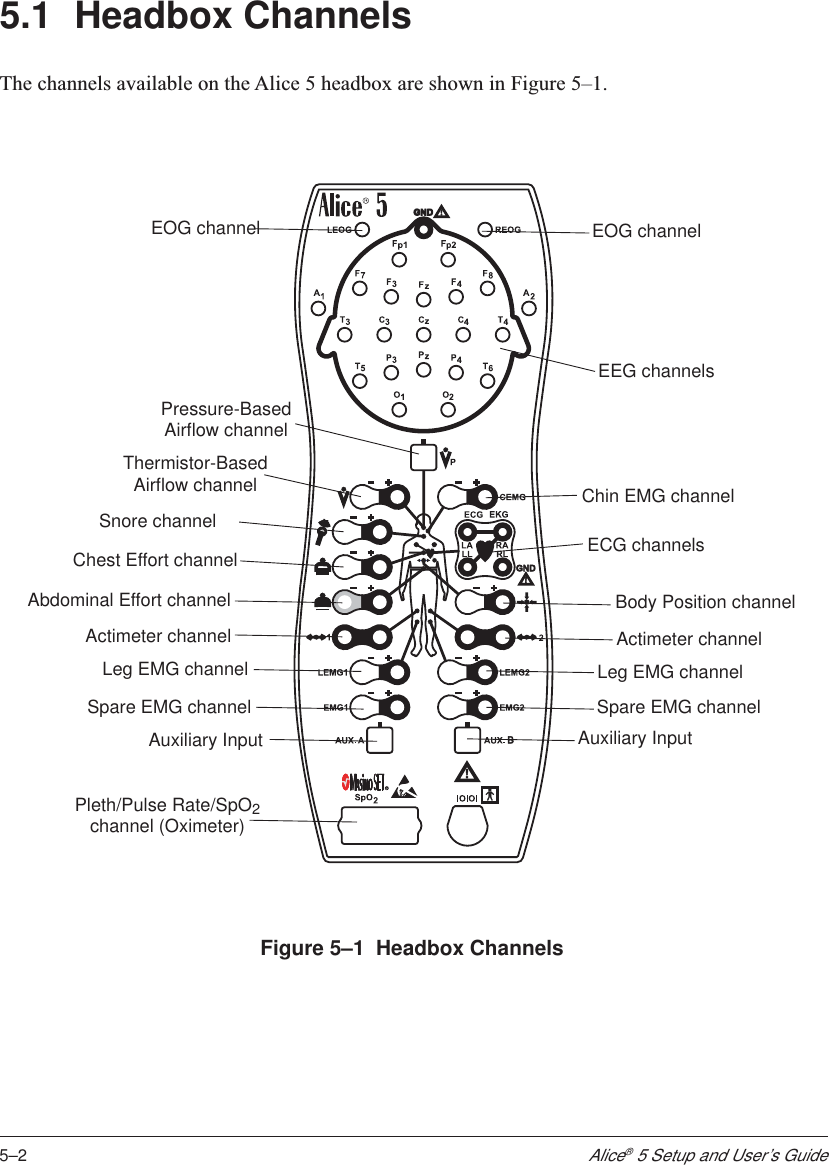
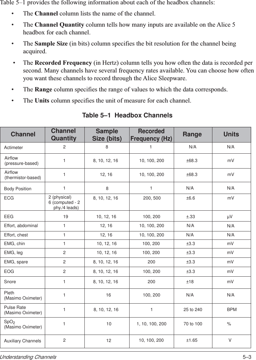
Respironics 1017226 Sleep Diagnosis System User Manual

Respironics Inc. Sleep Diagnosis System

User Manual

The Alice® 5 system is covered by the following patent: U.S. Patent No. 6,425,861.The information contained in this document is the property of Respironics, Inc. Except asspecifically authorized in writing by Respironics, the holder of this document (1) shall keep allinformation contained herein confidential and shall protect same in whole or in part from disclo-sure and dissemination to all third-parties, and (2) shall use same for operation and maintenancepurposes only.All information contained in this document is subject to change without notice. Respironicsreserves the right to make changes to equipment design or program components, as progress inengineering, manufacturing methods, or other circumstances may warrant.Alice®, Respironics®, and the Respironics logo are registered trademarks of Respironics, Inc.All other trademarks are owned by their respective companies.© 2004 Respironics, Inc. All rights reserved.
Table of ContentsiTable of ContentsChapter 1: Introduction...............................................................................................................1-11.1 Alice 5 System Contents ...............................................................................................1-21.2 Warnings and Cautions ..................................................................................................1-41.2.1 Warnings ..............................................................................................................1-41.2.2 Cautions ..............................................................................................................1-51.3 Intended Use ..................................................................................................................1-61.4 Hardware Component Overview ...................................................................................1-71.4.1 Data Flow through the Alice 5 Components .......................................................1-71.4.2 Alice 5 Base Station ............................................................................................ 1-91.4.2.1 Base Station Rear Panel ..........................................................................1-111.4.3 Headbox ..............................................................................................................1-141.5 Symbol Key ...................................................................................................................1-161.5.1 Headbox Symbols ...............................................................................................1-161.5.2 Base Station Back Panel Symbols ......................................................................1-171.5.3 Base Station Control Panel Symbols ..................................................................1-181.6 Acronyms and Definitions .............................................................................................1-181.7 Contacting Customer Service ........................................................................................1-21Chapter 2: Alice 5 Equipment Setup ..........................................................................................2-12.1 Before You Begin ..........................................................................................................2-22.2 Setting Up Your Network ..............................................................................................2-22.2.1 Network Setup Examples .................................................................................... 2-22.2.2 Using a Point-to-Point Setup ...............................................................................2-52.2.2.1 Map Your Facility’s Network Setup ........................................................2-62.2.3 Using a Wired Network Setup ............................................................................2-72.2.4 Using an Access Point Infrastructure Network ...................................................2-82.2.5 Connecting the Alice 5 Hardware Components ..................................................2-102.3 Integrating Alice 3 and Alice 4 Devices into your Alice 5 Network .............................2-162.4 Adding Accessories .......................................................................................................2-172.4.1 Installing Video Cameras and/or Video Servers .................................................2-17Chapter 3: Software Installation and Setup ................................................................................3-13.1 Alice Sleepware Software Installation ..........................................................................3-23.2 Adding Alice Devices ....................................................................................................3-63.2.1 Adding an Alice 5 Device ...................................................................................3-6
iiAlice® 5 Setup and User’s GuideChapter 4: Running Data Acquisitions .......................................................................................4-14.1 Overview .......................................................................................................................4-14.2 Patient Setup ..................................................................................................................4-24.2.1 Attaching EEG Electrodes ..................................................................................4-34.2.2 Attaching ECG Electrodes ..................................................................................4-64.2.3 Attaching Chest and Abdomen Effort Sensors ....................................................4-84.2.4 Attaching the EOG and EMG Electrodes ...........................................................4-94.2.4.1 EOG Electrodes .......................................................................................4-94.2.4.2 Leg EMG Electrodes ...............................................................................4-94.2.4.3 Chin EMG Electrodes .............................................................................4-94.2.5 Attaching the Airflow Sensor ..............................................................................4-104.3 Starting an Acquisition ..................................................................................................4-114.3.1 Check Your Cable Connections .......................................................................... 4-114.3.2 Check Your Equipment Performance .................................................................. 4-124.3.2.1 Check Impedance Using the Alice Sleepware ........................................4-124.3.2.2 Check Calibration ................................................................................... 4-134.3.3 Starting an Acquisition ........................................................................................4-154.2.4 Stopping an Acquisition ......................................................................................4-16Chapter 5: Understanding Channels ...........................................................................................5-15.1 Headbox Channels .........................................................................................................5-25.2 Base Station Auxiliary Channels ................................................................................... 5-105.2.1 Display Properties of Auxiliary Input Channels .................................................5-10Graphic Display Type .........................................................................................5-11Grapho-Numeric Display Type ...........................................................................5-11Numeric Display Type ........................................................................................5-125.2.2 Base Station Auxiliary Channel Descriptions .....................................................5-125.3 Therapy Device Channels ............................................................................................. 5-145.4 Derived Channels ..........................................................................................................5-17Chapter 6: Cleaning and Maintenance .......................................................................................6-16.1 Base Station, Headbox, and Patient Cable ....................................................................6-16.2 Sensors .......................................................................................................................... 6-26.2.1 EEG Electrodes ...................................................................................................6-26.2.2 ECG Sensors .......................................................................................................6-26.2.3 Airflow Sensors ...................................................................................................6-26.2.4 Snore, Actimeter, and Body Position Sensors .....................................................6-26.2.5 Effort Belts ..........................................................................................................6-2Chapter 7: Troubleshooting ........................................................................................................7-1Chapter 8: Specifications ............................................................................................................8-18.1 Device Size ....................................................................................................................8-18.2 Classifications and Ratings ........................................................................................... 8-28.3 Disposal .........................................................................................................................8-3Appendix A: EMC Information ..................................................................................................A-1Guidance and Manufacturer’s Declaration - Electromagnetic Emissions ................... A-1Guidance and Manufacturer’s Declaration - Electromagnetic Immunity ....................A-2
1–1IntroductionCHAPTER1IntroductionThe Alice® 5 Setup and User’s Guide contains instructions on how to set up your Alice 5 equip-ment so you can successfully run your sleep studies. It provides detailed information on:•Alice 5 equipment setup•Alice Sleepware software installation•Alice 5 equipment user instructionsRefer to the following Alice manuals for additional information:•The Alice® Sleepware™ User’s Guide contains information on how to use the diagnosticsoftware and describes the reporting features within Sleepware.•The Respironics Diagnostic Accessory Guide contains information about additionalaccessories you can use with your Alice system.Electronic copies of the user’s guides are available on the Alice Sleepware Software CD-ROM inPDF format.
1–2Alice® 5 Setup and User’s Guide1.1 Alice 5 System ContentsThe Alice 5 system contains the following hardware components, shown in Figure 1–1:Figure 1–1  Alice 5 Package ContentsBase StationHeadboxAC Power SupplyAC Power CordSpeakersMicrophone(Note: Style may vary from the one shown here.)Patient CableHeadbox Mounting BracketHeadboxShoulder StrapMouse PadAlice 5 Setup and User's GuideHeadbox Pouch(for use with the  Shoulder Strap)
1–3IntroductionYou may want to purchase additional accessories with your Alice 5 system. The following is ageneral list of accessories available. For a complete list, contact Respironics Customer Service oryour Respironics representative.• Computer workstations •     Computer monitors• Laptop computers •     Ethernet cards•     Computer speakers •     Network switches•Computer microphones •     Cables•Effort sensors •     Oximeter sensors• Oximeter probes •     Cannula•ECG Leads •     Video (web-server, cameras)•     Additional User GuidesNote: For more details on the accessories available, see the Respironics Diagnostic Acces-sory Guide.Note: It is recommended that you purchase the computer equipment you will use with theAlice system through Respironics to ensure the performance of the Alice Sleepwaresoftware. Customers do have the option of procuring their own equipment, butRespironics cannot guarantee the performance of Alice Sleepware on systems nottested by Respironics. For recommended computer specifications, see the AliceSleepware software packaging.Note: Computers used with the Alice 5 system must be UL 1950, IEC 60950, or EN 60950approved.Note: The style of the microphone, speakers, and some accessories such as the video cameramay differ from the ones shown in illustrations in this manual.
1–4Alice® 5 Setup and User’s Guide1.2 Warnings and CautionsCaution: US federal law restricts this device to sale by or on the order of a licensedhealthcare practitioner. This product should be used only under the supervision ofa physician.1.2.1 WarningsThe following warnings indicate the possibility of injury to the patient or the operator.•Be aware of signal interference, which can occur from external sources. Electronicsignals are required for the Alice 5 to function. Even though the system contains methodsand techniques that can provide protection from external sources of interference, youshould operate the system as follows:–Do not plug sensor lead wires into electrical outlets. Lead wire contact with electricaloutlets presents a serious shock hazard.–Place the system components on a sturdy and level surface. Do not place the basestation on carpeting.–Do not use the Alice 5 system within three feet of oxygen tanks or oxygen tents.–Do not operate the Alice 5 system in any explosive situation where flammable orexplosive sources are operational and in use.–If you suspect that the system is not working properly, do not attempt to service it.Contact your equipment provider or Respironics for assistance.–Always unplug the components from all electrical power sources (AC) whencleaning the system or any of its accessories. To remove AC power, unplug thepower supply cord from the mains outlet.–Do not connect telephone equipment to the auxiliary inputs.•If a patient has a cardiac pacemaker, consult with the patient’s physician prior to perform-ing the study.•The Alice 5 device and its accessories are not protected against the effect of cardiacdefibrillation. Remove all patient leads (applied parts) before performing cardiac defibril-lation.•Do not use the Alice 5 system in a Magnetic Resonance Imaging (MRI) environment orin close proximity to a high emissions source.•Do not touch the base station and the patient simultaneously, as this may create anelectrical shock hazard.•Periodically inspect the electrical cords, cables, and the power supply device for damageor signs of wear. Discard and replace any damaged parts before using.
1–5Introduction•Make sure that any wires attached to the patient are routed to reduce the likelihood ofstrangulation.•Pins of connectors identified with the ESD warning symbol should not be touched.Connections should not be made to these connectors unless ESD precautionary proce-dures are used. Precautionary procedures include methods to prevent buildup of electro-static discharge (e.g., air conditioning, humidification, conductive floor coverings, andnon-synthetic clothing), discharging one’s body to the frame of the equipment or systemor to earth or a large metal object, and bonding oneself by means of a wrist strap to theequipment or system, or to earth.•The conductive parts of electrodes and associated connectors, including the neutralelectrode, should not contact other conductive parts, including earth.•Do not use during high frequency surgical procedures or electrosurgery.1.2.2 CautionsThe following cautions indicate the possibility of damage to the device.•For all equipment used with the Alice 5 system, follow all of the manufacturer’s recom-mendations and instructions. Be sure to read, understand, and follow the instructions inthis manual and others that come with the system and its components. If you don’t have amanual, ask the equipment distributor or manufacturer for one.•Operation of the Alice system may be adversely affected by:–electromagnetic fields exceeding the level of 10 V/m in the test conditions of EN60601-1-2–the operation of high frequency (diathermy) equipment–defibrillators, or short wave therapy equipment–radiation (e.g., x-ray, CT)–magnetic fields (e.g., MRI)•Synthetic fabric from draperies or rugs can also cause interference due to static electric-ity. Touching an inanimate object (e.g., wall, crib) before handling the patient or thesystem often prevents static build-up problems.•Strong transmitter signals from TV, radio, airport, police, fire, and ambulance stationscould be received and interpreted as heart and/or breath signals. If you are located lessthan one mile from any of these sources, ask Respironics Customer Service to assist youin determining whether your system will operate properly.•Do not soak or immerse the base station or headbox in any liquid.•Never use an extension cord with the Alice 5 system. Always operate the device using aproperly grounded AC power outlet. If you are unsure whether a power outlet is properlygrounded, contact an electrician for assistance.
1–6Alice® 5 Setup and User’s Guide•Do not place liquids on or near the Alice 5 system. If liquids are spilled on the equipment,discontinue use until it can be determined that the device can be safely operated. ContactRespironics for assistance.•Do not operate the Alice 5 system during electrical storms. Information could be lost ordamaged.•Do not drop components of the Alice 5 system. If any of the devices are dropped,discontinue use until it can be determined that the device is fully operational. ContactRespironics for assistance.•Report problems with any of the components of the Alice 5 system. If the system is notworking properly, contact Respironics immediately for service.•Use only accessories that have been approved by Respironics.1.3 Intended UseThe Alice 5 system is a single-patient use, polysomnography system that is intended to record,display, and print physiological information for clinicians or physicians. These parameters arepresented graphically on a computer screen for diagnostic review, similar in application to theuse of a traditional paper-based polygraph recorder. The device will be used in hospitals, institu-tions, sleep center or clinics, or other test environments where adults or infant patients require thedocumentation of various sleep or other physiological disorders.This device does not provide alarms and is not intended for use as an automated apnea monitor. Itis not for continuous monitoring.The Alice 5 equipment collects the data from sensors placed on a patient and delivers the data toa computer running the Sleepware application. The Alice Sleepware application is a Windows-based software program designed to monitor, display, process, and download polysomnographicdata recorded with the Alice 5 equipment.Note: For information about using Microsoft Windows, refer to your Microsoft documenta-tion. For more information about Alice Sleepware, refer to the Alice Sleepware User’sGuide.
1–7Introduction1.4 Hardware Component OverviewThe Alice 5 equipment consists of the base station, headbox, polysomnographic sensors, andauxiliary input devices.The base station and headbox record, amplify, filter, and digitize various physiologic inputs. Itmay collect up to 55 channels of data. The base station stores the data locally on an internal harddisk until it is sent over a wired or wireless ethernet connection to a computer running the AliceSleepware application. Sleepware can display live or pre-recorded data in a resolution consistentwith the computer hardware specifications. Sound and video of the patient are available, and anintercom feature allows you to communicate with the patient remotely.The base station can also interface directly with several auxiliary input devices (e.g., EtCO2monitors, etc.).The two main components of your Alice 5 system are the base station and headbox. You can addadditional hardware components, such as video cameras, if needed. See Chapter 2 for informa-tion on how to set up video cameras. For information on additional Alice 5 accessories, refer tothe Respironics Diagnostic Accessory Guide.1.4.1 Data Flow through the Alice 5 ComponentsThe flow of the data through the Alice 5 system is as follows: From the patient, the sensors pickup physiologic events. Sensor cables carry the signal to the Alice 5 headbox or to an auxiliarydevice.If the data then gets carried to the Alice 5 base station via the headbox, the signal is amplifiedand treated before being transformed from analog to digital format. If the signal is sent to thebase station via an auxiliary input, it is not amplified by the base station because it was alreadyamplified and conditioned in the auxiliary unit.The signals are digitized and stored in the base station. If configured, they are then sent from thebase station to the computer running the Alice Sleepware diagnostic application.Figure 1–2 illustrates the flow of data during an Alice 5 acquisition.
1–8Alice® 5 Setup and User’s GuideBase StationHeadboxAuxiliary Device(optional)Computer RunningAlice SleepwarePatient withSensors AttachedEthernet ConnectionFigure 1–2  Data Flow During an Alice 5 Acquisition
1–9Introduction1.4.2 Alice 5 Base StationThe Alice 5 base station is a completely self-contained data collection device that is capable ofgathering and storing information without the use of an outside computer.The base station should be placed on a flat, stable surface close enough to allow for easy connec-tion to the headbox. The device should also be placed within easy access to an external AC powersource that is properly grounded.Figure 1–3 shows the base station and its control panel.Ready LEDRecord LEDAudio/Video LEDRecord Start/StopButtonInfraredTransceiverFigure 1–3  Alice 5 Base Station
1–10Alice® 5 Setup and User’s GuideThe control panel at the top of the base station has three LEDs:1. Ready – The top LED is the power indicator and has the following states:•Green – Indicates that power has been applied to the base station and it is ready foroperation.•Yellow – Indicates that power has been applied to the base station, but it is not ready foroperation.•Off – Indicates that power has not been supplied to the device.2. Record – The center LED is the acquisition indicator and has the following states:•Green – Indicates that a study is being recorded and there are no errors on the base stationor the headbox.•Flashing Yellow – Indicates that the headbox has been disconnected while a study is inprogress. In this state, the base station records zeros until the headbox is reconnected.•Off – Indicates that data is not being captured or recorded (i.e., a study is not in progress).3. Audio/Video – The bottom LED is the camera/microphone recording indicator and has thefollowing states:•Green – Indicates that video and/or sound is active or being recorded.•Off – Indicates that video and sound are not active or being recorded.In addition to the LEDs above, the control panel also includes the following button:•Record Start/Stop – You can use this button to start or stop a data acquisition directlyfrom the base station.  If you start an acquisition at the base station, the name and ID ofthe previous patient is used, and the default configuration is recorded. For more informa-tion on data acquisitions, see Chapter 4.Note: Data acquisitions can also be started from a computer running Alice Sleepware. Whenstarting acquisitions from a computer, you can enter specific patient information.The Infrared Transceiver on the front of the base station (shown in Figure 1–3) allows the basestation to communicate with a laptop computer. If you are using a laptop that does not have awireless card, the laptop can still communicate with the base station if it has infrared (IRDA)capability.
1–11Introduction1.4.2.1 Base Station Rear PanelFigure 1–4 shows the base station’s rear panel and its connections.Power SupplyHeadboxSpeakersMicrophoneAuxiliary InputsEthernetConnectionAntennaCOM 1 Serial Port (for Respironics  therapy devices)BNC Analog Signal ConnectorFigure 1–4  Base Station Rear PanelNote: All other connections on the rear panel, including USB ports ( ), the Accessory port,and the Com 2 Serial Connection port are not currently used.Note: Do not connect a video camera to the   port on the back of the base station. This isa BNC analog signal connector, not a video input connector.
1–12Alice® 5 Setup and User’s GuideOn the back of the base station, there are two LEDs located on the ethernet connection ( ):Network Present and Network Traffic. These LEDs function for both wired and wireless net-works.1. Network Traffic LED – The bottom LED has the following states:•Flashing Green – Indicates that there is traffic on the network.•Off – Indicates that there is no traffic on the network.2. Network Present LED – The top LED has the following states:•Flashing Yellow – Indicates that the only connection is to a wireless network.•Green – Indicates that the network is a wired network.•Off – Indicates that a network is not present.Auxiliary Input PortsYou can connect additional external medical devices using the auxiliary inputs on the back of thebase station. There are four ports available, but you can use a channel splitter to attach twodevices to each input. See the Respironics Diagnostic Accessory Guide for additional informationon using a channel splitter with the Alice 5.The following table contains the pin-out information for the auxiliary input ports. The table isspecific to auxiliary inputs 1 and 2, but you can use the same information for the remaininginputs (3/4, 5/6, etc.), respectively.Pin Number Pin Name Input/Output/Power1 Tip2 Ring 3 SleeveAux 2 Input (even)Aux 1 Input (odd)RtnInInGND 3.5 mm Plug(3)Sleeve(2)Ring (1)TipAuxiliary Ports 1 and 2
1–13IntroductionSerial Connection PortYou can connect Respironics CPAP or bi-level therapy devices to the Com 1 serial port on theback of the base station. The following table contains the proper pin-out information for the serialconnection port.Note: Contact Respironics Customer Service for a list of the therapy devices that arecompatible with Alice 5.123456789Pin Number Pin Name Input/Output/Power123456789CDRxDTxDDTRGNDDSRRTSCTSRIInInOutOutGNDInOutInIn
1–14Alice® 5 Setup and User’s Guide1.4.3 HeadboxThe Alice 5 headbox combines the neurological inputs and cardio-respiratory inputs into a singledevice. These signals are then sent to the Alice 5 base station. You can place the headbox inseveral different locations:•On a table or stand beside the patient’s head.•In the headbox mounting bracket attached to the wall behind the patient’s head.•Attached to a carrying strap that the patient can wear around the neck. This option isuseful if the patient needs to get up during the study so the connectors do not needremoved.•In the headbox pouch attached to a shoulder strap worn over the patient’s shoulder.Figure 1–5 illustrates the options for headbox placement.Figure 1–5  Headbox Placement Options
1–15IntroductionFigure 1–6 shows the Alice 5 headbox and defines the connections.Serial Connectionto the base stationOximeterConnectionAuxiliary Input Auxiliary InputSpare EMG Spare EMGLeg EMG Leg EMGActimeter ActimeterAbdominal Effort Belt Body Position SensorChest Effort BeltSnore SensorThermistor Flow SensorPressure-BasedFlow SensorChin EMGECG/EKGEEGA1 Reference ElectrodeLeft EOG Right EOGA2 Reference ElectrodeGround Connection*Ground Connection*Figure 1–6  Alice 5 Headbox* Note: Although there are two ground (GND) connections, you can only use one groundconnection at a time. You cannot use both simultaneously.Note: For EEG inputs, connect the left reference electrode to the A1 input jack on the leftside of the device. Connect the right reference electrode to the A2 input jack on theright side of the device.See Chapter 4 for more information on connecting sensors to the headbox.
1–16Alice® 5 Setup and User’s Guide1.5 Symbol KeyThe following symbols appear on the Alice 5 base station and headbox.1.5.1 Headbox SymbolsThermistor Flow SensorPressure Based Flow SensorChest Effort BeltAbdominal Effort BeltActimeter SensorLeg EMG SensorSpare EMG SensorAuxiliary Input SensorOximeter SensorSerial Connection to Base StationAuxiliary Input SensorSpare EMG SensorLeg EMG SensorActimeter SensorBody Position SensorRight EOG SensorLeft EOG SensorGroundLeft Arm SensorElectrocardiogram SensorLeft Leg SensorRight Arm SensorRight Leg SensorPositiveNegativeSnore Sensor (Vibration Sensor)Type BF Applied Part  Symbol Description!Attention, consult accompanying documentsBElectrostatic DischargeEuropean CE Declaration of ConformityNotified Body Approval for  Standards ComplianceCanadian/US Certification0123IPX1 Drip Proof EquipmentFront Symbol DescriptionBack
1–17Introduction1.5.2 Base Station Back Panel Symbols!Attention, consult accompanying documentsEuropean CE Declaration of ConformityNotified Body Approval for Standards ComplianceCanadian/US Certification0123Input Input/Output (on back panel) (connect to headbox)USB Port (connector)Connect Speaker (out)Serial Connection to PC or CPAPConnect Microphone (in)Ambient Sound Recording and /or IntercomAntenna NetworkOutput DC Power Type BF Applied Part  Symbol DescriptionIPX0Ordinary Equipment RatingClass II (Double Insulated)AC Power
1–18Alice® 5 Setup and User’s Guide1.5.3 Base Station Control Panel SymbolsReady (When green - Power is supplied, and the acquisition is ready to start)(When yellow - Power is supplied, but acquisition setup is not complete)Recording  (When green - Acquisition is proceeding without errors)(When flashing yellow - Acquisition setup is not complete)Record Start/Stop Button Audio/Video (When green - Video / Audio is being recorded and/or the intercom is active)Symbol Description1.6 Acronyms and DefinitionsThe following terms and acronyms appear in this manual:Acquisition A collection of polysomnographic data that has been acquiredduring a patient study.Ad-Hoc Network An Ad-hoc Wireless Local Area Network (WLAN) is a group ofdevices, each with a WLAN adaptor, connected as an independentwireless LAN.Alice Sleepware The Respironics software application that runs via the Windowsoperating system and that receives and analyzes physiologic datafrom Alice equipment.Alice Sleepware Starter Bar The component of the Alice Sleepware that appears at the top ofthe computer screen and is used during equipment setup forconfiguration and during data acquisitions to view settings orcontrol the optional microphone and camera.Base Station Part of the Alice system equipment used to storepolysomnographic data collected by the Alice headbox. This datacan then be copied/moved to a computer for use with the AliceSleepware software.BiPAP Bi-Level Positive Airway PressureCA Central apnea – A temporary cessation of airflow accompanying acessation of respiratory effort.
1–19IntroductionCPAP Continuous Positive Airway PressureConfiguration The set of channels used to acquire polysomnographic data.ECG Electrocardiogram – A recording of cardiac electrical activity. Insleep testing, this channel is used to assess heart rate and rhythm.EEG Electroencephalogram – A recording of electrical brain activity.With the EMG and EOG, the EEG is one of three basic variablesused to score wake and sleep and to identify sleep stages. The EEGis the primary variable for sleep staging.EMG Electromyelogram – A recording of muscle electrical activity. Thechin EMG is measured by surface electrodes, and along with theEEG and EOG, it is one of the three basic variables used to scorewake and sleep and to identify sleep stages.EOG Electrooculogram – A recording of voltage changes resulting fromshifts in position of the eye. Along with the EEG and EMG, theEOG is one of the three basic variables used to score wake andsleep and to identify sleep stages.EPAP Expiratory Positive Airway PressureEtCO2End tidal carbon dioxide, as detected by an end tidal CO2 monitor-ing device.Generic Channels Channels whose data the Alice 5 does not have an auto-scoringalgorithm for. Generic channels need definition regarding theirpresentation (display). Generic channels usually have as theirsource an auxiliary device connected to an auxiliary input on theAlice headbox. Generic channels may be displayed as numbers orgraphs. There are three display types for generic channels:Graphic, Grapho-Numeric, and Numeric.Graphic Display Type One of three display types for generic channels. A graphic displaytype is assigned when a channel’s data is most useful to theclinician when displayed as a graph (waveform) rather than anumber, and the data points of the curve are not clinically useful.In other words, the curve, not its data points, are important.Grapho-Numeric Display TypeOne of three display types for generic channels. A grapho-numericdisplay type is assigned when a channel’s data is most useful to theclinician when displayed as a graph (waveform) and the data pointsare also meaningful.Headbox A bedside remote amplifier that is part of the Alice system and isused to collect physiologic data from sensors placed on thepatient’s body.
1–20Alice® 5 Setup and User’s GuideInfrastructure Network An integrated wireless and wired LAN is called an infrastructureconfiguration.IPAP Inspiratory Positive Airway PressureIR InfraredLAN Local Area NetworkLED Light Emitting DiodeMAC Address Media Access Control address. This is a unique hardware addressthat identifies a device on a network. It is assigned by the manufac-turer and cannot be changed. This address can usually be found onthe device packaging.Montage A montage (as distinguished from an acquisition configuration) is away to display re-referenced EEG and EOG data during or after anacquisition. Each acquired EEG channel measures the difference inelectrical potential between a given (active) electrode and areference. The montage tool recombines EEG/EOG data in order todisplay the difference in potential between any two electrodes.Numeric Display Type One of the three display types for generic channels. A numericdisplay type is assigned when the data is most useful to theclinician when displayed as a number, rather than a waveform.OSA Obstructive Sleep Apnea – A temporary cessation of airflowwithout an accompanying cessation of respiratory effort.pH A measure of the acidity or alkalinity of a fluid. In sleep, thisgenerally refers to a measure of the acidity of fluid in the esopha-gus, detected by an esophageal pH probe.PLM Periodic limb movement, indicated by the change in leg muscletone as detected by the difference in electrical potential of two legEMG leads.Polysomnography Recording of  multiple channels of physiologic data during sleep.PSG PolysomnographyPTT Pulse Transit TimeREM Rapid Eye Movement – The stage of sleep with the highest brainactivity, characterized by enhanced brain metabolism and vividhallucinations, imagery, and dreams. During the REM stage,resting muscle activity is suppressed and there is a high awakeningthreshold to nonsignificant stimuli.SpO2Arterial oxygen saturation level via pulse oximetry.
1–21IntroductionWi-Fi Wireless Fidelity; generically refers to any type of 802.11 network.Any devices tested and approved as “Wi-Fi Certified” by the Wi-FiAlliance are certified as interoperable with each other.1.7 Contacting Customer ServiceIf you need product support, call the Respironics Customer Service department at 1-800-345-6443 (US or Canada only) and 1-724-387-4000.Additionally, you may contact Respironics Customer Service at the following email address:service@respironics.com
1–22Alice® 5 Setup and User’s Guide
2–1Alice 5 Equipment SetupCHAPTER2Alice 5 Equipment SetupThis chapter describes how to connect the hardware components included with the Alice 5system. It contains graphics illustrating the connections as well as detailed step-by-step instruc-tions.There are several possible ways to set up your Alice 5 system:•Wired point-to-point setup, where wired devices communicate directly with each other(e.g., base station to computer).•Wired network setup, where a switch is used to connect multiple devices to a LocalArea Network (LAN).•Wireless ad-hoc setup, a wireless networking framework in which devices communicatedirectly with each other, without the use of an access point.•Wireless Access Point Infrastructure network setup, where a device acts as a commu-nication hub for users of a wireless device to connect to a wired LAN.This chapter provides general instructions on how to set up each of these systems. The examplesprovided are suggested ways of positioning the equipment. You may alter the component setup asneeded.
2–2Alice® 5 Setup and User’s Guide2.1 Before You BeginBefore you set up your Alice 5 system, keep the following information in mind:•Map out your facility’s layout in advance so you know what type of equipment, cables,and accessories you will need.•Determine whether you will be setting up a wired or wireless network for Alice 5.  If youwill have a wired network with multiple devices connected, you will need a switch.•Respironics recommends that you set up the Alice system on its own network, indepen-dent of your facility’s network(s). System performance may be better on an independentnetwork.•Your cabling requirements will change depending on whether you use a point-to-pointsetup or a network setup. You will need a CAT-5 Crossover cable for a point-to-pointsetup, while a network setup requires a standard CAT-5 Patch cable.•The Alice 5 system does not support the Dynamic Host Configuration Protocol (DHCP),a protocol for assigning dynamic IP addresses to devices on a network. You must assignstatic IP addresses to your Alice 5 devices and to the computers you are running the AliceSleepware software on, as well as to any network video cameras or servers you use. SeeChapter 3, Software Installation and Setup, for additional information.2.2 Setting Up Your NetworkThis section describes how to install your system using wired or wireless networks.2.2.1 Network Setup ExamplesThis section provides example illustrations of various setups that are commonly used whenconfiguring Alice 5 networks. There are many possible configurations, but these will help youunderstand some of the basic connections and how the IP addresses are set up. The differentwired and wireless setups are described in greater detail in Sections 2.2.2 – 2.2.4.Note: It’s recommended that you first map your network setup before proceeding with theequipment installation instructions later in this chapter and the software installationdescribed in Chapter 3. You will need to determine what your network configuration isand what equipment you’ll be using (if you’ll need a switch, a video server, etc.) beforeyou start setting everything up.
2–3Alice 5 Equipment SetupExample 1192.168.1.1192.168.1.2Network SwitchAlice 5Base StationWorkstation192.168.1.1 192.168.1.2Alice 5Base StationWorkstation- CAT-5 Patch CableC5PC5PC5PC5X- CAT-5 Crossover CableC5XFigure 2–1 Basic Wired Network Setup Using a Switch or a Crossover CableNote: The IP addresses shown in Figures 2–1 through 2–4 are only examples. You will needto assign IP addresses that are appropriate for your facility’s network.Example 2Alice 5Base StationWorkstationVideo ServerVideo Camera192.168.1.1192.168.1.2192.168.1.3Network Switch- CAT-5 Patch CableC5PC5PC5PC5PFigure 2–2  Wired Network with Video Server and Camera
2–4Alice® 5 Setup and User’s GuideExample 3Alice 5Base StationWorkstationVideo ServerVideo Camera169.254.1.11192.168.1.2192.168.1.3169.254.1.2C5X- CAT-5 Crossover CableC5XFigure 2–3 Network Setup with Wireless DesktopExample 4Alice 5Base StationVideo ServerVideo Camera192.168.1.11192.168.1.2192.168.1.3LaptopWirelessAccess Point192.168.1.1192.168.1.100Workstation- CAT-5 Patch CableC5PC5P C5PC5PFigure 2–4  Access Point Infrastructure Network Setup
2–5Alice 5 Equipment Setup2.2.2 Using a Point-to-Point SetupIf you plan to connect the Alice 5 base station directly to the computer you will be using to viewdata, you may want to use a point-to-point wired setup or an ad-hoc wireless setup to install theequipment.Figures 2–5 and 2–6 show point-to-point and ad-hoc setup connections. In Figure 2–5, onedesktop computer is directly connected to an Alice 5 device using a CAT-5 crossover ethernetcable.Workstation Alice 5Base StationC5X- CAT-5 Crossover CableC5XFigure 2–5  Wired Point-to-Point SetupIn Figure 2–6, a laptop is connected to the Alice 5 device wirelessly via an ad-hoc setup.Alice 5Base StationWIFIConnectionLaptopw/WIFI CardFigure 2–6  Wireless Ad-Hoc Setup
2–6Alice® 5 Setup and User’s Guide2.2.2.1 Map Your Facility’s Network SetupYou can use the space on this page to map out your facility’s network configuration and the IPaddresses for each piece of equipment.
2–7Alice 5 Equipment Setup2.2.3 Using a Wired Network SetupIf you plan to have several patient rooms and several Alice 5 systems or computers, you maywant to set your equipment up using a wired network setup. Figure 2–7 provides an example.Note:Refer to IEC 60601-1-1 for definition of the patient environment.Control RoomBedroom 1Bedroom 2Bedroom 3NetworkSwitchWorkstation- CAT-5 Patch CableC5PC5PC5PC5PC5PC5PFigure 2–7  Wired Network Setup
2–8Alice® 5 Setup and User’s Guide2.2.4 Using an Access Point Infrastructure NetworkIf you plan to have multiple patient rooms with several Alice 5 systems and computers and youwant to connect a portion or all of your network wirelessly, you can use an Access Point Infra-structure network. Figures 2–8 and 2–9 show examples of possible setups.Figure 2–8 shows a network in which multiple computers are connected to multiple Alice 5devices through a wireless access point.Laptopw/WIFI CardAlice 5Base StationAlice 5Base StationWirelessAccess PointWorkstationw/WIFI CardFigure 2–8  Access Point Infrastructure Network Setup – Example 1Figure 2–9 shows a network in which multiple computers are connected to an Access Pointwirelessly, but the Alice 5 devices are connected to the network switch using ethernet cables, andthe switch is connected to the Access Point using an ethernet cable.
2–9Alice 5 Equipment SetupLaptopw/WIFI CardWirelessAccess PointBase StationBase StationNetworkWorkstationWorkstationSwitchBedroomsWireless Devices Control RoomsTablet PC- CAT-5 Patch CableC5PC5PC5P C5PC5P C5PFigure 2–9  Access Point Infrastructure Network Setup – Example 2
2–10Alice® 5 Setup and User’s GuidePower SupplyHeadboxSpeakersRespironicsTherapy Device*MicrophoneVideo Camera*Network Switch* Workstation** Additional equipment not included with your Alice 5 System2.2.5 Connecting the Alice 5 Hardware ComponentsOnce you have determined which type of setup you will be using (point-to-point, ad-hoc, wirednetwork, or access point infrastructure network), you can connect your Alice 5 equipment.Figure 2–10 provides a detailed illustration of how different devices and cables are connected tothe back panel of the base station. The steps that follow refer to many of the connectors shown inFigure 2–10.Figure 2–10  Base Station Back Panel
2–11Alice 5 Equipment SetupComplete the following steps to set up your Alice 5 hardware. Refer to Figure 2–12 for a detailedexample of how the final room setup might look.1. If you haven’t already done so, unpack your computer and set it up according to the instruc-tions supplied with it.2. Unpack your Alice 5 system and make sure that all of the components are included.3. Make sure that the base station is placed on a flat, stable surface close enough to allow foreasy connection to the headbox. The base station should also be placed within easy access toan external AC power supply that is properly grounded.4. Place the headbox on a table or stand above and behind the patient’s head, beside the patient’spillow, or on a nearby hook using the carrying strap supplied with your system. Or, use themounting bracket to mount the headbox on a wall.5. Connect the power cord to the AC power supply.6. Plug the pronged end of the power cord into a wall outlet.Caution: Never use an extension cord with the Alice 5 system. Always operate the deviceusing a properly grounded AC power outlet. If you are unsure whether a poweroutlet is properly grounded, contact an electrician for assistance.7. Connect the power supply’s cord into the Power Connector port (  ) on the back of thebase station.8. Plug one end of the Patient Cable into the headbox connector port (  ) on the back of thebase station.9. Plug the remaining end of the Patient Cable into the Serial Connection (  ) on the head-box (as shown in Figure 2–11).PatientCableFigure 2–11  Patient Cable Connection
2–12Alice® 5 Setup and User’s GuideNote: The ends of the Patient Cable are interchangeable. It does not matter which end youplug into the base station and which end you plug into the headbox.10. Follow Step A for point-to-point wired setups, Step B for wired network setups, or Step C forad-hoc or access point infrastructure setups.A. For Point-to-Point Wired Setups:–Plug a CAT-5 crossover cable into the Network port (  ) on the back of the basestation.–Then, plug the remaining end of the cable to your computer’s network interfaceconnector.B. For Wired Network Setups:–Plug a standard CAT-5 Patch cable into the Network port (  ) on the back of thebase station.–Then, plug the remaining end of the cable into an ethernet connection. For example,if you have set up your network switch in your control room, you can run the CAT-5Patch cables from the base stations in each patient room to the ethernet connectorson the switch, so that all base stations are plugged into the same network.–To connect your computer to the network, plug a CAT-5 Patch cable into yourcomputer’s network interface connector, and plug the other end of the cable into anethernet connection (e.g., a connector on a switch).C. For Wireless Ad-hoc or Access Point Infrastructure Setups:–Plug a standard CAT-5 Patch cable into the Network port (  ) on the back of thebase station.–Then, plug the remaining end of the cable into an ethernet connection.Note: In Step C, although you are configuring a wireless setup, you still need to perform thisstep when initially setting up your Alice 5 system. For network security reasons, thewireless feature is disabled when you first receive your Alice 5 device. In order toenable the wireless feature, you must first set up the device as a wired connection toallow your device to be seen on the network. Then, after you enable the wirelessfeature via the Sleepware software, remove the ethernet cable. Once the wirelessfeature is enabled, the system uses the wireless antenna attached to the Antennaconnector ( ) on the back of the base station to transmit data.11. If you are using a microphone for intercom/ambient sound recording, plug the male end of theMicrophone cable into the Microphone connector (  ) on the back of the base station. Plugthe remaining end of the Microphone cable into the microphone you are using on the patient.
2–13Alice 5 Equipment SetupNote: Once you install Sleepware and add your Alice devices (as described in Chapter 3),you can enable the audio feature by right-clicking on the Room button located on theStarter bar and selecting Audio/Video Settings from the  drop-down menu. See Section2.4, Adding Accessories, for instructions on setting the audio and video settings.12. If you are using speakers with your system, connect the green, male end of the Speaker cableinto the Speaker Connector ( ) on the back of the base station. Connect the other end ofthe cable directly into any basic-powered PC computer speaker.Note: If the technician is in a control room separate from the sleep lab, the speakers andmicrophone allow the technician to speak directly with the patient from the controlroom. The speakers and microphone work in the same one-way format as an intercom.Once you’ve installed the speakers, if you want to change the volume, you can adjust thevolume control on the speakers or you can use the volume control setting on your computer.13. To connect a Respironics therapy device (CPAP, Bi-Level, etc.) to the Alice 5 system, connectthe serial connector end of the therapy device’s Communications Cable into the Com 1 SerialConnection port (   ) on the back of the base station. Connect the remaining end of theCommunications Cable to the port on the back of the therapy device or to the Sleeplink card,if applicable. This allows you to control the therapy device directly through the Alice 5system. Refer to the therapy device’s manual for connection information.14. If desired, you can connect additional external medical devices, produced by other manufac-turers, using the Auxiliary Input connectors on the back of the base station. Refer to thesedevices’ manuals for additional information.Note: All other connectors on the base station (USB ports, Accessory ports, the Auxiliarychannel, and the Com 2 Serial Connection port) are not currently used.15. Install the Alice Sleepware software using the instructions found in Chapter 3.
2–14Alice® 5 Setup and User’s GuideFigures 2–12 and 2–13 provide a more detailed example of how a network setup may look.PowerSupplyHeadboxSpeakersMicrophoneBaseStationVideoCamera*NetworkSwitch*Workstation*RespironicsTherapy Device** Additional equipment not included with your Alice 5 SystemFigure 2–12  Detailed Wired Network Setup – Single Bedroom
2–15Alice 5 Equipment SetupWo rkstation*Wo rkstation HeadboxSpeakersMicrophoneHeadboxSpeakersMicrophoneBase Station 2Base Station 1BEDROOM 1BEDROOM 2CONTROL ROOMVideo Camera*NetworkSwitch*Video Server* Video Cameras** Additional equipment not included with your Alice 5 system.Figure 2–13  Detailed Wired Network Setup – Multiple Bedrooms
2–16Alice® 5 Setup and User’s Guide2.3 Integrating Alice 3 and Alice 4 Devicesinto your Alice 5 NetworkYou can connect Alice 3 and Alice 4 devices to your network and use them in combination withAlice 5 devices and Alice Sleepware.Figure 2–14 illustrates how these devices might be incorporated into your network.WorkstationWorkstationVideo ServerAlice 4 Base StationAlice 3 (Calvin) Base Station Video CamerasHeadboxSpeakersMicrophoneBase Station 2BEDROOMCONTROL ROOMVideo CameraNetworkSwitchFigure 2–14  Sample Network Containing Alice 3 and Alice 4 Devices
2–17Alice 5 Equipment Setup2.4 Adding AccessoriesThere are many additional accessories you can use with the Alice 5 system. See the RespironicsDiagnostic Accessory Guide for details on the many accessories available.This section provides instructions on how to set up video cameras and video servers with theAlice 5.2.4.1 Installing Video Cameras and/or Video ServersYou may want to install video cameras and/or video servers to use with your Alice system. Thereare a few setup options when using video cameras with the Alice 5 system:•Connect a video camera directly to the base station if your Alice 5 equipment is commu-nicating with your computer through a wireless interface.•Connect a video camera to a switch on your network.•Connect multiple video cameras (up to four) to a video server that is connected to yournetwork’s switch or hub. You must be using a network switch with your Alice 5 system touse a video server.Note: If your computer is wired to the base station, or if you are using a network switch thatis wired to the base station, you cannot connect a camera directly to the Alice 5device.Note: See the Respironics Diagnostic Accessory Guide to determine what video server iscompatible with the Alice 5 System and to order video cameras if needed. Refer to theinstructions included with your video server for more detailed product information.Decide which option you want to use, and then follow the installation instructions below.1. Connect your video equipment to the Alice 5 system using one of the following three configu-rations:a. If you are connecting a video camera directly to the base station, connect a CAT-5crossover cable to the network connector on the video camera, and connect the other endof the cable to the Network port (  ) on the back of the base station.b. If you are connecting a video camera to your network switch, connect a CAT-5 patchcable to the network connector on the video camera, and connect the other end of thecable to one of the ports on your switch.c. If you are connecting one or more video cameras to a video server:–Connect a CAT-5 patch cable to the network connector on the rear panel on the videoserver, and then connect the other end of the cable to an ethernet connection on yourswitch.
2–18Alice® 5 Setup and User’s Guide–If your camera has a BNC connector on it, connect a coaxial video cable to one ofthe video inputs (BNC connectors) on the front panel of the video server, andconnect the other end of the cable to the BNC connector on the camera. Repeat thisstep if you are adding more than one camera.Video Inputs(BNC Connectors)NetworkConnectorFigure 2–15  Video Server Front and Rear Panel ConnectionsNote: If your camera does not have a BNC connector and has a standard phono-type RCAconnector instead, you will need a BNC-to-RCA converter to connect the camera to thevideo server.2. Note the serial number on your video camera or on the bottom of the video server if you areusing the server. You need to know this to set the IP address.Note: If you are using a video server, you only need to assign the server an IP address, notthe cameras. However, if you are connecting a camera directly to the base station or toa switch, assign an IP address to the camera.Note: The serial number on the video equipment is the same as the MAC/Ethernet addressyou will enter in step 3 below (e.g., 00408c100086 = 00-40-8c-10-00-86).3. From a computer on your network, assign the video camera or video server (depending onyour setup) a unique IP address:•From your Windows operating system, start a DOS window by going to Start>Run andtyping cmd in the text box that appears. Click OK to access DOS.•Type the following command in the window that appears:
2–19Alice 5 Equipment SetupSyntax:arp -s <Video Camera or Server IP address> <MAC/Ethernet address>For example:arp -s 172.21.1.200 00-40-8c-10-00-86•Press Enter, and on the next line, type the following command:Syntax:ping -t <Video Camera or Server IP address>For example:ping -t 172.21.1.2004. You will now see “Request timed out” messages repeatedly appearing in the window.Note: If the “Request Timed Out” messages do not appear, and the message “DestinationHost Unreachable” appears instead, then the video equipment is not accessible onyour subnet. Refer to Chapter 7, Troubleshooting, for information on how to resolvethis problem.5. Connect the power supply to the video camera or server.Note: If you connected the power supply before entering the DOS commands, unplug it andreconnect it at this time.6. Approximately 25 seconds after connecting the power supply, the message“Reply from <Video Camera or Server IP address>” appears. If using the video server, makesure the power indicator on the front panel of the server is permanently lit and that thenetwork indicator flashes intermittently.Note: If you do not receive the “Reply from...” message, refer to Chapter 7, Troubleshooting,for information on how to correct the problem.7. Exit ping. The installation is complete, and you are ready to access the video camera(s) fromyour browser.Note: The remaining steps in this section explain how to enable video through Alice Sleep-ware once you have installed the software. For instructions on software installation,see Chapter 3.
2–20Alice® 5 Setup and User’s Guide8. To enable the video feature through Alice Sleepware, go to your Starter Bar, right-click on theRoom button, and select Audio/Video Settings from the drop-down menu, as shown in Figure2–16.Figure 2–16  Accessing the Audio/Video Settings9. Choose your multimedia and image settings in the screen shown in Figure 2–17.10. In the Camera/Server settings, type in the IP address of the video camera or video server andthe port number that the video camera is connected to (Port # 1-4 if using the video server).Note: The Camera/Server Port number will always be 80.Note: See the Alice Sleepware User’s Guide for more information on these settings and fordetails on how to view and save video, etc..Figure 2–17  Audio/Video Settings Screen
2–21Alice 5 Equipment SetupNote: After you have enabled the settings, the Audio/Video icon ( )will appear on yourRoom button, and you can right-click on it to access the screen shown in Figure 2–17if you want to modify your audio/video settings.The video will appear on your screen.Note: If the video does not appear after you have completed all of the steps above, refer toChapter 7, Troubleshooting, for information on how to resolve the problem.
2–22Alice® 5 Setup and User’s Guide
3–1Software Installation and SetupCHAPTER3Software Installation and SetupOnce you have installed your Alice 5 equipment, you will need to install the Alice Sleepwaresoftware on your computer(s). This chapter describes how to install the software and how to adda device so your computer can communicate with your Alice system. When adding a device, youcan specify whether you are connecting through a wired or wireless interface.Before installation, please note the following:1. You must be logged onto the computer as “administrator” to install the software.2. If one or more restricted users will be running Alice Sleepware, the permissions on theinstallation directory must be opened so that everyone has both read and write access toall applicable files.Note: When you change access permissions on a folder, Windows will prompt you with achoice between applying changes to “this folder only” or to “this folder, subfolders,and files.” Choose the second option to apply changes to all of the folders/files.3. If acquisition data will be shared by multiple restricted users, or if the user recording thedata and the user scoring the data are two different restricted users, then the permissionson all data locations must be opened so everyone has read and write access.After installation is complete, if multiple restricted users will be using the software, you will alsoneed to complete the following steps:4. Create all of the data locations needed (see the Alice Sleepware User’s Guide).5. As administrator, change the security rights attached to the following folders: c:\alice5 (orthe directory where the software has been installed), c:\al5_data, (and c:\al4_data orc:\al3_data if you have acquisition data in those locations) and any other data locationsyou’ve created, to allow all users full control of these directories.Note: After installation is complete, you can change the user type back to “restricted” on thecomputer if necessary.
3–2Alice® 5 Setup and User’s Guide3.1 Alice Sleepware Software InstallationComplete the following steps to install the Alice Sleepware software.Note: It is recommended that you close all other software programs before installing theAlice Sleepware software.1. Insert the Sleepware CD into your computer’s CD drive.2. In the first screen, shown in Figure 3–1, select Install Software.Note: The version numbers shown on the screens in this manual are for example only. Yoursoftware version may differ from the one shown here.Figure 3–1  Alice Sleepware Start-Up ScreenThe Installation Wizard automatically launches.Note: You can also select View Documentation on this screen to access a list of availableAlice Sleepware and Alice 5 manuals. These manuals are available in PDF format onthe CD. You must have Adobe® Acrobat® Reader to view the manuals.
3–3Software Installation and Setup3. In the next screen, select one or both of the following items if they apply to you, as shown inFigure 3–2.•Alice Sleepware (required) – This item must be selected (it is automatically checked).•Auto-launch Alice Starter – Check this box if you want the Alice Starter to automati-cally launch upon logging in. If you do not check this box, you will have to manuallyopen the Starter bar by either double-clicking the Alice Starter icon on your desktop, orright-clicking on the   icon in the lower right corner of your screen and then selectingLaunch Alice Starter from the menu options.Figure 3–2  Software Installation Startup Screen4. Click the Next button.
3–4Alice® 5 Setup and User’s Guide5. Specify the directory where you want the software program to be installed (or use the defaultdirectory shown), and click Install, as shown in Figure 3–3.Figure 3–3  Installation Directory ScreenA progress bar appears, indicating that the installation is in process, as shown in Figure 3–4.Figure 3–4  Installation Progress Screen
3–5Software Installation and SetupAfter the installation is complete, the following software shortcut icons are automaticallyplaced on your desktop for easy access to the software:Figure 3–5  Sleepware Shortcut IconsAdditionally, if you selected the option to automatically launch the Alice Starter, the AliceSleepware starter bar appears at the top of your screen, as shown in Figure 3–6. The Starterbar is a toolbar that you can use during equipment setup for configuration and during dataacquisitions to view settings or control the optional microphone and camera.Figure 3–6  Alice Sleepware Starter BarNote: If the Alice Sleepware software did not install properly, refer to Chapter 7, Trouble-shooting for help resolving this problem.
3–6Alice® 5 Setup and User’s Guide3.2 Adding Alice DevicesThrough the Alice Sleepware software, you can add Alice 3, 4, or 5 devices. This section de-scribes how to add Alice 5 devices. For instructions on how to add an Alice 3 or 4 device, refer tothe Alice Sleepware User’s Guide.3.2.1 Adding an Alice 5 DeviceNote: The Alice 5 system does not support the Dynamic Host Configuration Protocol(DHCP), a protocol for assigning dynamic IP addresses to devices on a network. Yo umust assign a static IP address to your Alice 5 device.To add an Alice 5 device, complete the following steps:1. Left-click on the Configure button on the Alice Sleepware starter bar, and select Add/ModifyDevice as shown in Figure 3–7.Figure 3–7  Add/Modify Device2. The Add/Modify Device menu appears, as shown in Figure 3–8. Select Alice 5.Figure 3–8  Add/Modify Device Menu
3–7Software Installation and Setup3. A list of Alice 5 devices that are configured to communicate with your computer appears. Ifthere are no Alice devices currently configured, the list will be empty, as shown inFigure 3–9.Figure 3–9  List of Configured Alice DevicesClick Add to configure an Alice 5 device.
3–8Alice® 5 Setup and User’s Guide4. The Alice 5 Configuration Wizard appears as shown in Figure 3–10. Click Next.Figure 3–10  Alice 5 Configuration Wizard – Main Screen5. The Preparing Your PC screen appears, as shown in Figure 3–11.Figure 3–11 Preparing Your PC Screen
3–9Software Installation and SetupNote: If you set up a device on your network with a specific IP address and then later changethe IP address of that same device, you must return to the Add/Modify screens andreconfigure the device using its new IP address; otherwise, the device will no longer befound on the network.If you want to update your settings, click the Edit buttons to the right of the fields and do thefollowing:•In the Computer Description field, type in a name for your computer so the AliceSleepware software can identify your computer on the network. You should choose aname that will help you easily identify the computer on the network when you are tryingto set up Alice devices to communicate with that particular computer.•The Select IP Address for Your PC field will already be filled in if the software hasdetected an IP address for your computer. If several IP addresses are included, choose theaddress that you want your computer to use to communicate with the Alice 5 device.If more than one address appears and you are not sure which address is correct, completethe steps below to find your computer’s IP address:a. On your computer, go to Start > Control Panel  and double-click on NetworkConnections.Note: If you are using Windows 2000 or the Windows Classic theme in Windows XP, you willneed to go to Start>Settings>Control Panel in the above step.b. Double-click on Local Area Connection (or Wireless Network Connection if youare on a wireless network) to access the following screen:Figure 3–12  Local Area Connection Status Screen
3–10Alice® 5 Setup and User’s Guidec. Select the Support tab to view your computer’s IP address, as shown in Figure 3–13.Figure 3–13  Local Area Connection Status – Support Tabd. Click Close and then select this address in the Select IP Address for Your PC fieldon the Preparing Your PC screen. Click Next.
3–11Software Installation and Setup6. The Alice 5 Connection Mode screen appears, as shown in Figure 3–14.  Specify whetheryour Alice 5 device is connected through its wired or wireless interface, and then click Next.Figure 3–14  Alice 5 Connection Mode ScreenAttention! On this screen, you are specifying the type of connection from the base station tothe network, not the connection from the computer to the network.To help determine if your network is wired or wireless, consider the following:•If your base station is wirelessly connected to the access point, is your access pointconnected to the network switch via an ethernet cable? If so, you must choose the wirednetwork option. Even though your base station is connected to the access pointwirelessly, the access point is then connected to the rest of the network via a wiredconnection.•If all of the devices in your network are wirelessly connected to the access point, choosethe wireless network option (see Figure 2–8 for an example illustrating this setup).Note: If you are still not sure whether your network is wired or wireless, contact yournetwork administrator.
3–12Alice® 5 Setup and User’s GuideNote: Refer to Chapter 2 for additional information on wired and wireless network setups.The Select an Alice 5 device screen appears, as shown in Figure 3–15.Figure 3–15  Search for Alice 5 devices Screen7. Select the Alice 5 device that you want to add. The list shows all devices that are available.Highlight the device and click Next to continue the installation process.Note: If you are installing a new device or are not sure which device to choose from the list,find the serial number on the back panel of your Alice 5 base station, and then choosethe device in the list that has that same serial number.What if My Device Isn’t Listed?If you cannot find your Alice 5 device in the list provided in Figure 3–15, you will need to placea check mark by the statement “I did not find the device I want to add, the serial number is notlisted in the above list,” and click Next.
3–13Software Installation and SetupThe screen shown in Figure 3–16 appears if you are connecting the Alice 5 device through awired interface.Alice 5 - Room 1192 168 12NextFigure 3–16  Alice 5 Device Network Settings Screen – Wired•Type in a unique name for the Alice 5 base station in the first field. This name will helpyou identify the base station on the network.•In the TCP/IP Address field, type in the unique IP address of the Alice 5 base station youare adding.•Click Next and go to Step 9.
3–14Alice® 5 Setup and User’s GuideIf you are connecting the Alice 5 device through a wireless interface, when you place a checkmark by the statement “I did not find the device I want to add, the serial number is not listed inthe above list,” in Figure 3–15 and click Next, the screen shown in Figure 3–17 appears.Figure 3–17 Alice 5 Device Network Settings Screen – Wireless•Type in a unique name for the Alice 5 base station in the first field. This name will helpyou identify the base station on the network.•Check the Enable Wireless Interface box to enable wireless. The wireless setting isdisabled by default when the base station is shipped, so you must check this box in orderto configure the base station’s wireless interface.•Select Ad-Hoc if you are using a direct, peer-to-peer network, or select Infrastructure(Via an Access Point) if your network is connected via a wireless access point.•In the Wireless General Settings, type in the Service Set Identifier (SSID). This is theunique name shared among all points in a wireless network. The SSID is required if yourAlice 5 base station is connected through a wireless interface. It is case sensitive andmust not exceed 32 characters. Make sure this setting is the same for all points in yourwireless network.
3–15Software Installation and Setup•If you selected Ad-Hoc for the wireless network mode, you will need to select theChannel you are using in the Wireless General Settings. All devices on the network mustshare the same channel in order to function correctly. There are 11 possible channels thatyou can choose from. Similar to channels on a telephone, you can choose a channel thatdoes not have much traffic on it to ensure that the wireless connection speed is as fast aspossible. Enter any number from 1-11. If you are not sure what channel to choose,contact your network administrator.Note: If you select Infrastructure for the wireless network mode, you will not need to selecta channel. The Channel field will be grayed out.•In the TCP/IP Address field, type in the unique IP address of the Alice 5 base station youare adding.•Select the desired Wireless Encryption setting. You can choose from three levels ofencryption: Off (no encryption), On (64 bits), or On (128 bits).Off means that there is no security for the data being transferred on the wireless networkbetween the base station and the computer.On (64-bit) encryption allows you to enter a 10-character key in the Key field. Thelonger or more complicated the key, the more security the encryption may achieve.On (128-bit) encryption allows you to enter a 26-character key in the Key field, whichprovides even greater network security.•If you’ve enabled encryption, type in the appropriate key (10 characters for 64-bitencryption or 26 characters for 128-bit encryption). The key can consist of any numberranging from 0 to 9 and/or any letter ranging from A to F.•Click Next and go to Step 9.
3–16Alice® 5 Setup and User’s Guide8. If your device appeared in the list of devices on the screen shown in Figure 3–15, after youhighlight the device you want to add and click Next, the screen shown in Figure 3–18appears. This screen will be different depending on whether you specified that you have awired or wireless network on the screen shown in Figure 3–14. If you specified that the Alice5 is connected through a wired interface, the screen shown in Figure 3–18 appears. If youspecified that the Alice 5 is connected through a wireless interface, the screen shown in Figure3–19 appears. Follow the instructions for the screen that applies to you.The screen in Figure 3–18 appears when you are configuring the Alice 5 device’s wiredinterface.Figure 3–18  Alice 5 Device Wired Network Settings•In the first field, type in a unique name for the Alice 5 base station. This name will helpyou identify the base station on the network.
3–17Software Installation and Setup•In the Alice 5 Network Settings fields, type in the TCP/IP address, subnet mask, andgateway information for the Alice 5 device so your computer will be able to fullycommunicate with the device on the network.a. In the TCP/IP Address field, type in the unique TCP/IP address for your Alice 5device. The Alice 5 device, like your computer, needs to be connected to yourlab or hospital’s computer network in order to exchange data with the computerson that network.Note: If you set up your Alice 5 network on its own subnet, you may not need to change thedevice’s IP address to a unique address. Each Alice 5 device has its own unique wiredand wireless IP address based on the serial number on the device, so changing thedevice’s IP address will not be necessary if you use this type of configuration.Note:If you do not know the TCP/IP address for your Alice 5 device, contact your networkadministrator.b. Type in the correct Subnet Mask for your Alice 5 device. A subnet mask is like afilter that is applied to a message’s destination IP address. Its objective is todetermine whether the local network is the destination network. On TCP/IPnetworks, subnets consist of all devices whose IP addresses have the sameprefix.Note: If you do not know what subnet you are on, contact your network administrator.c. If your Alice 5 device is not on the same subnet as your computer, you need toenter the correct Gateway address in the Gateway field. Enter the IP address ofyour network’s Gateway (such as a router), which is used to allow for contactbetween multiple networks. If your network does not have a Gateway, then leavethis field blank.Note: If you do not know the correct Gateway address, contact your network administrator.
3–18Alice® 5 Setup and User’s GuideThe screen in Figure 3–19 appears if you are configuring the Alice 5 device’s wirelessinterface.Figure 3–19  Alice 5 Device Wireless Network Settings•In the first field, type in a customized name for your Alice 5 device so you and yourcolleagues can easily identify the device on your network in the future.•If you want to connect your device through a wireless interface, check the EnableWireless Interface box. The wireless setting is disabled by default when the basestation is shipped, so you must check this box in order to configure the base station’swireless interface.•Select Ad-Hoc if you are using a direct, peer-to-peer network, or select Infrastruc-ture (Via an Access Point) if your network is connected via a wireless access point.•The Alice 5 device comes with default TCP/IP settings. You should change thesesettings to suit your network.a. In the TCP/IP Address field, type in the unique TCP/IP address for your Alice 5device. The Alice 5 device, like your computer, needs to be connected to yourlab or hospital’s computer network in order to exchange data with the computerson that network.
3–19Software Installation and SetupNote: If you set up your Alice 5 network on its own subnet, you may not need to change thedevice’s IP address to a unique address. Each Alice 5 device has its own unique wiredand wireless IP address based on the serial number on the device, so changing thedevice’s IP address will not be necessary if you use this type of configuration.Note:If you do not know the TCP/IP address for your Alice 5 device, contact your networkadministrator.b. Type in the correct Subnet Mask for your Alice 5 device. A subnet mask is like afilter that is applied to a message’s destination IP address. Its objective is todetermine whether the local network is the destination network. On TCP/IPnetworks, subnets consist of all devices whose IP addresses have the sameprefix.Note: If you do not know what subnet you are on, contact your network administrator.c. If your Alice 5 device is not on the same subnet as your computer, you need toenter the correct Gateway address in the Gateway field. Enter the IP address ofyour network’s Gateway (such as a router), which is used to allow for contactbetween multiple networks. If your network does not have a Gateway, then leavethis field blank.Note: If you do not know the correct Gateway address, contact your network administrator.•If you are using the device on a wireless network, set your Wireless Encryptionsettings and general settings.a. The Service Set Identifier (SSID) is the unique name shared among all points ina wireless network. The SSID is required if your Alice 5 base station is con-nected through a wireless interface. It is case sensitive and must not exceed 32characters. Make sure this setting is the same for all points in your wirelessnetwork.Note: Contact your network administrator if you do not know the correct SSID.b. If you selected Ad-Hoc for the wireless network mode, you will need to selectthe Channel you are using in the Wireless General Settings. All devices on thenetwork must share the same channel in order to function correctly. There are 11possible channels that you can choose from. Similar to channels on a telephone,you can choose a channel that does not have much traffic on it to ensure that thewireless connection speed is as fast as possible. Enter any number from 1-11. Ifyou are not sure what channel to choose, contact your network administrator.
3–20Alice® 5 Setup and User’s GuideNote: If you select Infrastructure for the wireless network mode, you will not need to selecta channel. The Channel field will be grayed out.c. You can choose from three levels of encryption: Off (no encryption), On (64bits), or On (128 bits).Off means that there is no security for the data being transferred on the wirelessnetwork between the base station and the computer.On (64-bit) encryption allows you to enter a 10-character key in the Key field.The longer or more complicated the key, the more security the encryption mayachieve.On (128-bit) encryption allows you to enter a 26-character key in the Key field,which provides even greater network security.d. If you’ve enabled encryption, type in the appropriate key (10 characters for 64-bit encryption or 26 characters for 128-bit encryption). The key can consist ofany number  ranging from 0 to 9 and/or any letter ranging from A to F.Note: All points in your wireless network must use the same key to utilize encryption.•Click Next once you are finished updating your settings.
3–21Software Installation and SetupThe Acquisition Data Recipient screen appears, as shown in Figure 3–20.Figure 3–20  Acquisition Data Recipient Screen9. Select where you want to store your data, and then click Next.•Select Option 1 to store the data on your computer.•Select Option 2 if you do not want the data stored on this computer. The data will bestored on the base station, unless you run this wizard again on a different computer anddesignate that computer as the data recipient.Note: If you want data from the Alice 5 device to be sent to another computer, you must runthis Wizard on another computer in the network and choose Option 1 for that com-puter.
3–22Alice® 5 Setup and User’s Guide10. If the wireless interface is disabled (because you did not check the Enable Wireless Interfacebox in Figure 3–19), the Wireless Interface Disabled screen appears, as shown in Figure 3–21.Figure 3–21  Wireless Interface Disabled ScreenThis screen indicates that the wireless interface on the Alice 5 device is currently disabled. Toenable the wireless interface, you will need to edit the device properties by clicking on theEdit button in the Alice 5 Add/Modify Device dialog box. See the Alice Sleepware User’sGuide for more information.Note: This screen will not appear if the wireless interface has been enabled.11. Click Finish to complete the process of adding a device.12. The Alice 5 Device List screen appears, displaying the devices that are configured on yourcomputer. The device you just added should appear in the list, as shown in Figure 3–22.
3–23Software Installation and SetupFigure 3–22  Alice 5 Device List ScreenAdditionally, once the device is successfully added, a Room button appears in your AliceSleepware starter bar, indicating the device’s status, as shown in Figure 3–23.Figure 3–23  Alice 5 Device Status IndicatorNote: You can also edit devices through the Alice 5 Configuration Wizard and delete or viewdevice properties through the Add/Modify Device screens. For more information, referto the Alice Sleepware User’s Guide.
3–24Alice® 5 Setup and User’s Guide
4–1Data AcquisitionCHAPTER4Running Data AcquisitionsThis chapter describes how to set up the patient so the data you need will be properly recorded,and instructs you on how to start and stop an acquisition. See Chapter 5 for information on thechannels that can be recorded, and see the Alice Sleepware User’s Guide for detailed instructionson using the software.4.1 OverviewThe Alice Sleepware software allows you to view and score data acquisitions while an acquisi-tion is in progress. It can also download and organize the data after an acquisition has beenrecorded. Data acquisitions are sorted by patient identity (e.g., name and ID number), thusproviding tracking of patient recording history. Multiple acquisitions performed on one patientmay be easily located within the database.Using Alice Sleepware, you can view raw waveform data in various time and montage formats. Adetailed view of the recording can be seen by scrolling through the data. You may select thechannels displayed on the screen and the color of the raw data, and print any raw data screen orgroups of screens. Global patterns or trends for the recording may be viewed via the use of1-hour or 10-hour summary screens. You can view video of the patient while they sleep, and youcan save streaming video or snapshots along with the sleep data.Alice Sleepware automatically detects physiologic events such as apnea, hypopnea, snoring,periodic limb movements, heart rate, arrhythmia, pH, and arousal. Events may also be distin-guished according to their context (e.g., an apnea with an associated heart rate or saturationdecrease). Alice Sleepware also recognizes a number of neurological events for staging adultsleep and cardio-respiratory patterns or activity for staging infant sleep.
4–2Alice® 5 Setup and User’s GuideYou can validate detected events, add additional events, remove events, or change the event type,duration, or position of a detected event. Based upon the validation, Alice Sleepware computesrelevant statistical values. The values may be displayed in a report format that is user-configurable. You can print the reports immediately or display them for on-screen review. Youcan also design custom report formats using the custom report feature.4.2 Patient SetupNote:Only trained personnel should use the Alice 5 system.Once you have installed your Alice 5 equipment and the Alice Sleepware software, you are readyto begin collecting data. You will need to attach the appropriate patient sensors from the headboxto the patient to acquire the data you need.Note: The Alice system supports the placement of EEG sensors using 10-20 ElectrodePlacement standards only. The 10-20 Electrode Placement standards were developedto provide consistent application of EEG sensors for recording brain wave data. Thissystem is based on measurements from four standard points on the head: the nasion,the inion, and the left and right periauricular points. You should mark and prepareeach position before actually applying the electrodes.The age of the patient determines the acquisition type and the type of data collected. There aretwo acquisition types:•Infant – The patient age for this acquisition type is less than six months. During record-ing of an Infant acquisition, the base station scores sleep using cardio-respiratory stabilityand actimetry. Likewise, after recording, Alice Sleepware scores sleep using cardio-respiratory stability and actimetry.•Adult – The patient age for this acquisition type is six months or older. During recordingof an Adult acquisition, the base station doesn’t score sleep. After the recording, AliceSleepware scores sleep using EEG and EMG data (by default).You can collect EEG data for Infant acquisition types, but Alice Sleepware does not use it toscore Pneumo sleep stages because EEG patterns are not fully developed until after humans reachthe age of six months.The acquisition type is different from the sleep scoring method. After the recording, you candetermine (using Alice Sleepware) whether sleep is scored using Neuro or Pneumo sleep stages.By default, the Alice Sleepware software associates adult acquisitions with Neuro sleep stagesand infant acquisitions with Pneumo sleep stages.See Chapter 5, Understanding Channels, for information about the channels that the Alice 5equipment supports. See Figures 1–4 and 1–6 for the locations to attach devices to the Alice 5equipment. You can attach sensors to the patient in any order.
4–3Data AcquisitionLeft Frontal Polar EEGRight Central EEGLeft Temporal EEGRight Parietal EEGLeft Parietal EEGRight Frontal Polar EEG Right Frontal EEGLeft Anterior Temporal EEG  Site DescriptionLeft Central EEGRight Anterior Temporal EEGLeft Frontal EEGFp1Fp2F3F4F7F8C3*C4*P3P4T3T4 Right Temporal EEGT5 Left Posterior Temporal EEGT6 Right Posterior Temporal EEGA2* Right Reference (right ear)A1* Left Reference (left ear)IsogroundGroundO1* Left Occipital EEGO2* Right Occipital EEG* Recommended by Rechtschaffen and KalesFz Frontal Zero EEG (mid-line)Cz Central Zero EEG (mid-line)Pz Parietal Zero EEG (mid-line)Note: If you have sensors from auxiliary devices such a pH machines, oximeters, apneamonitors, etc., follow the manufacturer’s instructions for attaching the sensors to thepatient.4.2.1 Attaching EEG ElectrodesYou should attach the EEG electrodes specified by your facility’s protocol and based on theconfiguration you choose. Table 4–1 lists the typical EEG sites from which data is collectedduring a sleep study.Table 4–1  Typical EEG Sites for Collecting Data
4–4Alice® 5 Setup and User’s GuideComplete the following steps to attach the EEG sensors to the patient:1. Following the manufacturer’s recommendations, attach the EEG leads to the patient’s scalpaccording to your facility’s procedures.Note: Respironics recommends that you use standard gold-cup electrodes for all EEGconnections.2. Decide whether you want to set the sensors up contralaterally or ipsilaterally. In the U.S.,adult studies use a contralateral setup, while infant studies always use an ipsilateral setup. InEurope, an ipsilateral setup is used.•Ipsilateral setups: Plug the A1 reference electrode lead (on the left side of the patient’shead) into the A1 input on the left side of the headbox, and plug the A2 referenceelectrode lead (on the right side of the patient’s head) into the A2 input on the right sideof the headbox.•Contralateral setups: Plug the A1 reference electrode lead (on the left side of the patient’shead) into the A2 input on the right side of the headbox, and plug the A2 referenceelectrode lead (on the right side of the patient’s head) into the A1 input on the right sideof the headbox.3. Plug the main EEG electrode leads into the appropriate connectors on the Alice 5 headbox.4. Place the Isoground electrode on the center of the patient’s forehead, and plug the lead intothe Isoground input on the Alice 5 headbox.Caution: If you use an EEG Isoground, do not use the left ECG lead.
4–5Data AcquisitionFigure 4–1 shows the locations of the EEG inputs on the Alice 5 headbox.These are the inputsfor the main EEGelectrodes(see Table 4–1for details)A2 Reference ElectrodeIsogroundattaches hereA1 Reference ElectrodeIsogroundattaches hereFigure 4–1  EEG Inputs on the Alice 5 Headbox
4–6Alice® 5 Setup and User’s Guide4.2.2 Attaching ECG ElectrodesThe Alice 5 system supports a single lead ECG or a 6-lead ECG. The single lead ECG uses twoor three wires from the headbox (the right leg is optional, depending on whether an EEGIsoground is also used with the patient). The 6-lead ECG uses three or four wires from theheadbox (right leg optional), and Alice calculates the six channels by cross-referencing thesignals.Table 4–2 lists the wire colors.Table 4–2  ECG Standard ProtocolsLead IILead IIType Lead NumberLead IRA (right arm) = WhiteLA (left arm) = BlackRL (right leg) = GreenNote: Do not connect the RL lead if youare using an EEG Isoground.Single Lead ECG6-Lead ECGColorsNorth American Headbox (according to AAMI, AHA-Code, or US Code)RA (right arm) = WhiteLA (left arm) = BlackRL (right leg) = GreenNote: Do not connect the RL lead if youare using an EEG Isoground.RA (right arm) = WhiteLL (left leg) = RedInternational Headbox (according to IEC-Code or EU-Code)Lead II RA (right arm) = RedLA (left arm) = YellowRL (right leg) = BlackNote: Do not connect the RL lead if youare using an EEG Isoground.Single Lead ECGLead IILead I6-Lead ECG RA (right arm) = RedLA (left arm) = YellowRL (right leg) = BlackNote: Do not connect the RL lead if youare using an EEG Isoground.RA (right arm) = RedLL (left leg) = Green
4–7Data AcquisitionComplete the following steps to attach the ECG electrodes to the patient:1. Refer to Table 4–2 and choose the standard protocol for your area.2. Snap the ECG leads onto adhesive electrode patches.3. Attach the patch for the right arm to the top right side of the patient’s chest, approximatelyone inch (2.54 cm) below the collarbone.4. Attach the patch for the left arm to the top left side of the patient’s chest, approximately oneinch (2.54 cm) below the collarbone. The green lead is for the ECG Ground. For a single-leadECG, you are finished with this procedure. If you are doing a 6-lead ECG, proceed to Step 5.5. Attach the patch for the right leg on the patient’s right side at the lowest rib. Do not place thepatch forward toward the patient’s stomach; it should be placed directly on the patient’s side.6. Attach the patch for the left leg on the patient’s left side at the lowest rib. Do not place thepatch forward toward the patient’s stomach; it should be placed directly on the patient’s side.Caution: If you use an EEG Isoground, do not use the left ECG lead.7. Plug the other ends of the ECG leads into the appropriate locations on the Alice 5 headbox,shown in Figure 4–2.ECG/EKGFigure 4–2  ECG Inputs on the Alice 5 Headbox
4–8Alice® 5 Setup and User’s Guide4.2.3 Attaching Chest and Abdomen Effort SensorsComplete the following steps to attach the chest and abdomen sensors to the patient:Note: If you want to use another method for monitoring an infant’s breathing effort (forexample, an apnea monitor), follow the manufacturer’s guidelines for attaching thesensors.1. Place the chest effort belt around the patient’s chest so that the Velcro® is in the center of thechest and the black fasteners are evenly aligned with the patient’s nipples. The connectorshould hang straight in front of the patient.2. Plug the lead into the Alice 5 headbox.3. Place the abdominal belt around the patient’s stomach so that the vinyl part of the sensor isdirectly over the navel and does not rotate around the torso. The fasteners on the belt shouldbe aligned with the patient’s hips. The connector should hang straight in front of the patient.Warning: For infants, do not tighten the belt to the point of impeding the infant’s breathing.Also, check the tension of the effort belts before and after feedings. As the infanteats, his or her belly may expand and the belts may become uncomfortably tight.4. Plug the lead into the Alice 5 headbox.Figure 4–3 shows the chest and abdomen sensor locations on the headbox.AbdominalEffort BeltChest Effort BeltFigure 4–3  Chest and Abdomen Sensor Inputs on the Alice 5 Headbox
4–9Data Acquisition4.2.4 Attaching the EOG and EMG Electrodes4.2.4.1 EOG ElectrodesComplete the following steps to attach the EOG electrodes to the patient.1. Attach the EOG leads to the patient.2. Plug the leads into the appropriate inputs on the headbox, as shown in Figure 4–4.4.2.4.2 Leg EMG Electrodes1. Place the Leg EMG leads on the patient according to your facility’s specifications. Thereshould be two leads on each limb to be monitored. Using only one lead per limb can result ina faulty signal.2. Plug the pair of leads for each limb into the appropriate inputs on the headbox, as shown inFigure 4–4.4.2.4.3 Chin EMG Electrodes1. Attach the Chin EMG to the patient.2. Plug the lead into the Chin EMG input on the headbox, as shown in Figure 4–4.Spare EMG Spare EMGLeg EMG Leg EMGLeft EOGattaches here Right EOGattaches hereChin EMGattaches hereFigure 4–4  EOG and EMG Inputs on the Alice 5 Headbox
4–10Alice® 5 Setup and User’s Guide4.2.5 Attaching the Airflow SensorComplete the following steps to attach the airflow sensor to the patient:1. Make sure you have the proper size sensor for your patient; both adult and infant sizes areavailable.2. For the pressure-based sensor, position the nasal pressure cannula above the upper lip with thecannula protruding slightly into the nostrils. Trim if necessary per the manufacturer’s guide-lines.3. For the thermistor sensor, position the sensor so that the flexible tabs fit under the nostrils.Pinch the tabs back 90° so that they are comfortable, yet not touching the skin and notprotruding into the nares. The tabs bend out, away from the patient’s face. The logo on thethermistor sensor is readable to the technician if the sensor is applied properly.Caution: Use caution when placing the sensor on the patient. To avoid cuts or irritation tothe skin, do not place the sensor too close to the nares.4. Drape the leads over the patient’s ears and connect the input to the Alice 5 headbox.5. If desired, tape the leads to the patient’s cheeks to help hold the sensor in place.Figure 4–5 shows the location of the airflow sensor inputs on the headbox.Thermistor Flow SensorPressure-BasedFlow SensorFigure 4–5  Airflow Sensor Inputs on the Alice 5 Headbox
4–11Data AcquisitionNote: You may have additional sensors from auxiliary devices such as pH machines,oximeters, apnea monitors, etc. These can be connected to the auxiliary input ports onthe back of the Alice 5 base station. See Chapter 1 for more information about theauxiliary input ports. Follow the manufacturer’s instructions for attaching thesesensors to the patient.4.3 Starting an AcquisitionBefore you start running an acquisition, you should review your cable connections and checkyour equipment as specified below.4.3.1 Check Your Cable ConnectionsReview your cable connections as described below before starting an acquisition.1. Check the sensor connections.Verify that each sensor is plugged into the appropriate connector on the Alice 5 headbox.Refer to Figure 1–6 and Section 4.2, Patient Setup, for more information.Verify that the Patient Cable is connected properly from the headbox to the base station. SeeFigures 2–10 and 2–11.2. Check the auxiliary device connections (if applicable).Verify that each auxiliary device is connected to the base station using the auxiliary inputspecified during the channel setup. See Chapter 5, Understanding Channels, for moreinformation.3. Check the base station connections.If you are using a wired network connection, make sure the ethernet cable is inserted into theethernet port on the back of the base station, as described in Chapter 2, Alice 5 HardwareSetup. Use one of the following cables:•CAT-5 Crossover Cable – Connects the base station directly to the computer runningAlice Sleepware software•CAT-5 Patch Cable – Connects the base station to a switch or ethernet connector
4–12Alice® 5 Setup and User’s Guide4.3.2 Check Your Equipment PerformanceYou should verify that the Alice 5 equipment is operating properly before starting an acquisition.Check impedance and calibration by completing the following procedures.4.3.2.1 Check Impedance Using the Alice SleepwareThe Alice 5 allows you to view impedance values at anytime during your study without impact-ing the physiological data that is being recorded. You won’t lose any physiological signals whenviewing impedance. To check impedance, complete the following steps:1. Set up the appropriate sensors.Note: The impedance feature works for the EEG, EOG, ECG, and EMG channels.2. Check all of the required cable connections as described in Section 4.3.1.3. Start an acquisition as described in Section 4.3.3.The Alice equipment begins capturing data from the sensors.4.  Click on the Imped. button while viewing the acquisition through Sleepware.The Sleepware software continuously displays the impedance value for each channel. Thechannel tabs to the left of each channel displayed indicate the impedance value by color:•A red tab indicates a high impedance value (a poor connection).•A dark green tab indicates a moderate impedance value (a fair connection).•A light green tab indicates a low impedance value (a good connection).Note: The channel label tab always indicates the impedance status, regardless of whether ornot you have pressed the Imped button. The actual impedance value is displayed whenyou press Imped.Note: The threshold values for impedance are user-configurable.Note: The impedance values are also available for review after the acquisition is recorded.
4–13Data Acquisition5. Use the information in Table 4–3 to determine whether further action is needed.Table 4–3  Electrode ImpedanceReplace the electrode using your lab's procedures.Consider changing the electrode using your lab'sprocedures.Impedance Recommended ActionNone. The sensor has a good connection.> 10 OhmsBetween 5k Ohmsand 10k Ohms< 5k Ohms4.3.2.2 Check Calibration1. Set up the sensors as described in Section 4.2.2. Connect all of the required cables and check the connections as described in Section 4.3.1.3. Start an acquisition as described in Section 4.3.3.The Alice equipment begins capturing data.4. In the On-line View window that appears, click on the Calib. button in the toolbar to generatea 100 mV signal on the ECG, EEG, EMG, and EOG channels. The Alice Sleepware displaysthe calibration signal in the waveform.5. Let the process run for at least 30 seconds, then click the button again.
4–14Alice® 5 Setup and User’s GuideCheck Bio-Calibration1. Set up the sensors as described in Section 4.2.2. Connect all of the required cables and check the connections as described in Section 4.3.1.3. Start an acquisition, as described in Section 4.3.3.The Alice 5 equipment begins capturing data.4. Ask the patient to lie on his or her back with arms along the body, eyes closed, and breathingregularly and gently. Test the sensors by asking the patient to follow the instructions in Table4–4 below.Table 4–4  Checking the SensorsWithout moving their head, have the patient close the eyelids and slowly move the eyes right and left repeatedly for ten seconds. Next, have the patient close the eyelids and slowly move the eyes up and down for ten seconds.Have the patient relax the jaw for five seconds, then contract the jaw by biting for three seconds, then relax again. Repeat thisthree or four times.Sensor ActionHave the patient breathe at a steady rhythm for 15 secondswhile making a snoring sound during inspiration, or have the patient count from 1 to 10.EOGChin EMGMicrophoneAbdominal and chesteffort, thermistor orpressure cannulaairflow.Have the patient breathe through the nose at a steady rhythm forfive seconds, then repeat by breathing through the mouth.Next, have the patient hold their breath for five seconds and then release.Leg EMG Have the patient contract a calf muscle for one second, then relax for one second; repeat five times. Repeat for the other calf.Have the patient point their toes, bend forward, hover, andrepeat.EEGs Have the patient open the eyelids, relax, and look straightahead for ten seconds. Then, have the patient close the eyelids,relax, and keep eyes facing straight ahead for ten seconds.
4–15Data Acquisition4.3.3 Starting an AcquisitionTo start the data acquisition, complete the following steps:1. Configure the Communication Settings for connection to the Alice 5 device you are using (seethe Alice Sleepware User’s Guide for instructions on configuration).2. If the Alice Starter module is not already running on your computer, double-click on the AliceStarter icon (  ) .The name of your device appears in the Starter bar at the top of the computer screen, alongwith the words “Awaiting Acquisition” as shown in Figure 4–6.Figure 4–6  Starter Bar and Device Awaiting Acquisition3. Click on the name of the device.The Acquisition Launch screen appears as shown in Figure 4–7.Figure 4–7  Acquisition Launch Screen4. Click on Start to begin the acquisition.The On-Line View screen appears, displaying all of the acquisition data. Green on the AliceStarter bar and the On-Line View screen indicates that the connection is successful and theacquisition is recording.
4–16Alice® 5 Setup and User’s GuideNote: It is recommended that you start an acquisition through the Sleepware software.However, if this is not available, you can press the Record Start/Stop button on thebase station. The Record LED is green while the base station records data.Refer to the Alice Sleepware User’s Guide for additional information on starting acquisitions.4.2.4 Stopping an AcquisitionTo stop an acquisition, click the Stop button on the On-Line View screen in Sleepware.Note: It is recommended that you stop an acquisition through the Sleepware software.However, if this is not available, you can press the Record Start/Stop button on thebase station twice to stop the acquisition. The Record LED turns off when the basestation stops recording data.
5–1Understanding ChannelsCHAPTER5Understanding ChannelsChannels refer to the different types of data collected by the auxiliary devices and sensorsconnected to the patient. The set of channels used in any particular sleep study is referred to as aconfiguration.You can configure the channels based on the type of information you need to collect for thestudy. Once you set up the patient and have the data coming in from the channels you configured,you can use the Alice Sleepware to filter channels, create a montage, etc. Refer to the AliceSleepware User’s Guide for information on how to build configurations and create montages.There are four types of Alice 5 channels:•Headbox channels•Base Station auxiliary channels•Therapy device channels•Derived channelsThese are discussed in the sections that follow.
5–2Alice® 5 Setup and User’s Guide5.1 Headbox ChannelsThe channels available on the Alice 5 headbox are shown in Figure 5–1.Pleth/Pulse Rate/SpO2channel (Oximeter)Auxiliary Input Auxiliary InputSpare EMG channel Spare EMG channelLeg EMG channel Leg EMG channelActimeter channel Actimeter channelAbdominal Effort channel Body Position channelChest Effort channelSnore channelThermistor-BasedAirflow channelPressure-BasedAirflow channelChin EMG channelECG channelsEEG channelsEOG channel EOG channelFigure 5–1  Headbox Channels
5–3Understanding ChannelsTable 5–1 provides the following information about each of the headbox channels:•The Channel column lists the name of the channel.•The Channel Quantity column tells how many inputs are available on the Alice 5headbox for each channel.•The Sample Size (in bits) column specifies the bit resolution for the channel beingacquired. • The Recorded Frequency (in Hertz) column tells you how often the data is recorded persecond. Many channels have several frequency rates available. You can choose how oftenyou want these channels to record through the Alice Sleepware.•The Range column specifies the range of values to which the data corresponds.•The Units column specifies the unit of measure for each channel.Table 5–1  Headbox Channels2Channel ChannelQuantityActimeterAirflow (pressure-based)SampleSize (bits)RecordedFrequency (Hz)Range Units811 8, 10, 12, 16 10, 100, 200 ±68.3 mVAirflow (thermistor-based) 112, 16 10, 100, 200 ±68.3 mVBody Position 181 N/A N/AECG 2 (physical)6 (computed - 2      phy./4 leads)8, 10, 12, 16 200, 500 ±6.6 mVEEG 19 10, 12, 16 100, 200 ±.33 µVEffort, abdominal 1 12, 16 10, 100, 200 N/A N/AEffort, chest 1 12, 16 10, 100, 200 N/A N/AEMG, chin 1 10, 12, 16 100, 200 ±3.3 mVEMG, leg 2 10, 12, 16 100, 200 ±3.3 mVEMG, spare 2 8, 10, 12, 16 200 ±3.3 mVEOG 2 8, 10, 12, 16 100, 200 ±3.3 mVSnore 1 8, 10, 12, 16 200 ±18 mVPleth(Masimo Oximeter) 116 100, 200 N/A N/APulse Rate(Masimo Oximeter) 1 8, 10, 12, 16 1 25 to 240 BPMSpO2(Masimo Oximeter) 1101, 10, 100, 200 70 to 100 %N/A N/AAuxiliary Channels 212 10, 100, 200 ±1.65 V
5–4Alice® 5 Setup and User’s GuideEach physical input channel is described in more detail below:1ActimetryThe actimetry channel type is used to sense motion signals from the patient. Actimetry is oneof the channels by which the Alice Sleepware scores sleep in infant configurations, so it is anecessary channel in an infant configuration. The channel may also be used in adult configu-rations, but is usually not as important because EEG is available for scoring sleep.With Alice 5, you can set customized parameters for this channel using the Alice Sleepware.Please refer to Table 5–1 for a detailed description of actimetry channel features. Aftercustomizing your configuration, you can use the Label function to enter a text description foryour configuration of up to eight characters.2Airflow (Pressure-based or Thermistor-based)The airflow channels are used to display data from a device that measures the patient’sairflow. You can use the airflow sensor channel type by connecting a Respironics thermistoror pressure cannula airflow sensor to the headbox.Note: If you label this channel “Flow,” the Alice Sleepware can scan the data and automati-cally score apneas and hypopneas. Refer to the Alice Sleepware User’s Guide for moreinformation.You can customize parameters for this channel. Refer to Table 5–1 for a detailed descriptionof airflow channel features. After customizing your configuration, you can use the Labelfunction to enter a text description for your configuration of up to eight characters.Note: Therapy device or auxiliary airflow channels are also available when you connect aRespironics therapy device to the COM 1 serial port on the back of the base station, orwhen you connect a third-party airflow sensor to an auxiliary input on the basestation. See Sections 5.2 and 5.3 for more information.
5–5Understanding Channels3Body PositionThe body position channel tells you the orientation of the patient’s body in the bed. The bodyposition sensor can report five possible positions:•Supine (patient is sleeping on their back)•Prone (patient is sleeping on their stomach, facedown)•Right side•Left side•UprightYou can select customized parameters for this channel.  Please refer to Table 5–1 for adetailed description of Body Position channel features. After customizing your configuration,you can use the Label function to enter a text description for your configuration of up to eightcharacters.4ECGThe ECG channel type is used to display data from an electrocardiogram channel. To use thischannel, connect an ECG electrode to the ECG inputs on the headbox as needed. See Chapter4 for additional information.You can set customized parameters for this channel. Please refer to Table 5–1 for a detaileddescription of ECG channel features. After customizing your configuration, you can use theLabel function to enter a text description for your configuration of up to eight characters.Note: An auxiliary ECG channel is also available when connecting an ECG monitoringdevice to one of the auxiliary inputs on the back of the base station. See Section 5.2 formore information.Note: The RR channel is used to display R-wave to R-wave data that Alice computes from theECG input signal. See Section 5.4 for more information about the RR channel.
5–6Alice® 5 Setup and User’s Guide5EEGThe EEG channel type is used to display data from an electroencephalogram channel.Note: The Alice system supports the placement of EEG sensors using 10-20 ElectrodePlacement Standards only. For more information, see Chapter 4.You can select customized parameters for this channel. Please refer to Table 5–1 for a detaileddescription of EEG channel features. After customizing your configuration, you can use theLabel function to enter a text description for your configuration of up to eight characters.Selecting the Reference Specification:In the Alice Sleepware, you can specify whether you want to set the sensors up contralaterallyor ipsilaterally. In the U.S., adult studies use a contralateral setup, while infant studies alwaysuse an ipsilateral setup. In Europe, an ipsilateral setup is used.•Ipsilateral setups: Plug the A1 reference electrode lead (on the left side of the patient’shead) into the A1 input on the left side of the headbox, and plug the A2 referenceelectrode lead (on the right side of the patient’s head) into the A2 input on the right sideof the headbox. In Sleepware, for configurations referenced ipsilaterally (on the sameside of the head), you would specify A1 for the left channel’s reference electrode and A2for the right channel’s reference electrode.•Contralateral setups: Plug the A1 reference electrode lead (on the left side of thepatient’s head) into the A1 input on the right side of the headbox, and plug the A2reference electrode lead (on the right side of the patient’s head) into the A2 input on theright side of the headbox. In Sleepware, for configurations referenced contralaterally(across the head), you would specify A1 for the right channel’s reference electrode andA2 for the left channel’s reference electrode, thus producing channels like C3A2, O1A2,etc.Note: The Alice 5 base station defaults to a contralateral configuration.
5–7Understanding Channels6Effort – Abdominal and Chest (Respiration)The respiration channel type is used to display chest and abdomen effort signals and trans-thoracic impedance signals.The Alice system provides two effort channels: thoracic effort and abdominal effort. Addi-tional effort channels must be input using the auxiliary inputs. The Alice Sleepware scans alleffort channels to detect apneas on the airflow channel. The Alice system also allows you tomonitor trans-thoracic impedance, which can be acquired from an infant monitor or otherauxiliary device.You can use the effort channel type by connecting the chest and abdominal effort belts to theinputs on the headbox.Note: Abdominal and chest effort auxiliary channels are also available if you connect athird-party respiration measuring device to an auxiliary input on the rear of the basestation. See Section 5.2 for more information.You can set customized parameters for this channel. After customizing your configuration,you can use the Label function to enter a text description for your configuration of up to eightcharacters.7EMG (Chin and Spare)The EMG channel type is typically used to display data for the chin EMG and the two spareEMGs, but it can be used for any electromyogram channel.Note: The Leg EMG channel type is described in #8, below.You can select customized parameters for this channel.  Please refer to Table 5–1 for adetailed description of EMG channel features. After customizing your configuration, you canuse the Label function to enter a text description for your configuration of up to eight charac-ters.8EMG (Leg)The leg EMG channel type is used to display data from limb movement detection channels.If you use both leg EMG inputs, note that the single leg EMG channel combines the data fromboth inputs.You can select customized parameters for this channel. Please refer to Table 5–1 for a detaileddescription of leg EMG channel features. After customizing your configuration, you can usethe Label function to enter a text description for your configuration of up to eight characters.
5–8Alice® 5 Setup and User’s Guide9EOGThe EOG channel type is used to display data from an electrooculogram channel. You canselect customized parameters for this channel. After customizing your configuration, youcan use the Label function to enter a text description for your configuration of up to eightcharacters.10 SnoreThe snore channel type is used to display data from a tracheal vibration sensor. This isnot a sound sensor. A typical use of this channel in sleep studies is to measure snoring.The snore input is not calibrated.You can select customized parameters for this channel. Please refer to Table 5–1 for adetailed description of snore channel features. After customizing your configuration, youcan use the Label function to enter a text description for your configuration of up to eightcharacters.11 PlethThe pleth channel type is used to display (as a waveform) changes in arterial blood flowdetected by the Masimo sensor.You can select customized parameters for this channel. Please refer to Table 5–1 for adetailed description of pulse channel features. After customizing your configuration, youcan use the Label function to enter a text description for your configuration of up to eightcharacters.12 Pulse RateThe pulse rate channel type is used to display numerical data from the Masimo pulseoximeter. To use the pulse rate channel type, connect a finger probe through a patientinterface cable to the oximeter connection on the headbox.You can set customized parameters for this channel. Please refer to Table 5–1 for adetailed description of pulse rate channel features. After customizing your configuration,you can use the Label function to enter a text description for your configuration of up toeight characters.
5–9Understanding Channels13 SpO2The SpO2 channel type is used to display blood oxygen saturation data from the internaloximeter or from an external device.You can use the SpO2 channel type by connecting the Masimo oximeter sensor to theoximeter connection on the headbox (see Figure 1–6).Note: An SpO2 auxiliary channel is also available when you connect a third-party oximeterto an auxiliary input on the back of the base station. See Section 5.2 for more informa-tion.You can set customized parameters for this channel. After customizing your configura-tion, you can use the Label function to enter a text description for your configuration ofup to eight characters.Conversion:You can configure parameters for this channel type so that the input signal is displayedcorrectly in the Alice Sleepware. See the Alice Sleepware User’s Guide for more informa-tion.
5–10Alice® 5 Setup and User’s Guide5.2 Base Station Auxiliary ChannelsThere are eight auxiliary input ports on the base station. You can use these ports to connect third-party therapy or monitoring devices to the Alice 5. Depending on the auxiliary devices you use,there are many possible auxiliary input channels available. Some of the key channels that you canreport on are described later in this section. See the instructions that came with your auxiliarydevice for information on specific channels available for that device.5.2.1 Display Properties of Auxiliary Input ChannelsThere are three display types for auxiliary input channels: Numeric, Graphic, or Grapho-Numeric. These are used to display a signal from any device that has an analog output. Table 5.2describes these generic display types. In the Sleepware software, you can choose which displaytype you want to use depending on your channel configuration. Use this table to help you decidewhich display type to use with a particular signal.Table 5–2  Display Properties of Auxiliary Input ChannelsUse This Channel Type... When...NumericAppearance of ChannelThe unit's measurements make the most sense when viewed as a number.Number: The line of numbers moves up and down as the valuesincrease or decrease.GraphicThe unit's measurements make the most sense when viewed as a waveform. The points thatdefine the wave are representativeof the numerical value received.Waveform: Use the referenceline tool in the Alice Sleepware todisplay data values.Note: The input signal cannot becalibrated.Grapho-NumericThe unit's measurements make the most sense when viewed as a waveform, but each point thatdefines the wave is a usable,meaningful value.Waveform, but the input signalcan be calibrated.Use the reference line tool in the Alice Sleepware to display datavalues.
5–11Understanding ChannelsEach auxiliary channel display property is described in greater detail below.Graphic Display TypeThe graphic display type allows you to display any signal as a waveform. Examples of suchsignals are airflow, effort, plethysmograph, etc. Generally, the graphic display type is designed toproduce a waveform for signals whose sample values are not given in meaningful units.Because the graphic display type is multi-purpose, the Alice Sleepware cannot analyze the datarecorded on a channel using this display type. This differentiates the graphic display type fromstandard channel types, such as the airflow channel. Both provide waveforms, but Alice can onlyscan the standard channel type, not the channel using the graphic display.See the Alice Sleepware User’s Guide for information on how to select the graphic display typewhen viewing auxiliary channel data.Grapho-Numeric Display TypeThe grapho-numeric display type allows you to display any signal as a waveform, and alsoallows you to calibrate the input signal by converting it to a specific number of units over adefined voltage range.Because the grapho-numeric display type is multipurpose, the Alice Sleepware cannot analyzethe data recorded on a channel using this display type. This differentiates the grapho-numericdisplay type from standard channel types, such as the airflow channel. Both provide waveforms,but Alice can only scan the standard channel type, not the channel using the grapho-numericdisplay.See the Alice Sleepware User’s Guide for information on how to select the grapho-numericdisplay type when viewing auxiliary channel data.Conversion:You can configure parameters for this display type so that the input signal is displayed correctlyin the Alice Sleepware. See the Alice Sleepware User’s Guide for more information.
5–12Alice® 5 Setup and User’s GuideNumeric Display TypeThe numeric display type allows you to display a signal from an auxiliary device as a series ofnumerical values. Examples of such devices are oximeters, EtCO2 monitors, pH units, CPAP orbi-level devices, etc. Any device that has an analog output can be viewed using the numericdisplay type, though some signals are better viewed as graphs.Because the numeric display type is multipurpose, the Alice Sleepware cannot analyze the datarecorded on it. This differentiates the numeric display type from standard channel types, such asthe SpO2 channel. Both provide numerical data, but Alice can only scan the standard channeltype, not the channel using the numeric display type.See the Alice Sleepware User’s Guide for information on how to select the numeric display typewhen viewing auxiliary channel data.Note: The default frequency for numerical data is 1 Hz, as this is the maximum frequency atwhich the screen in the Alice Sleepware can display numerical data.Conversion:You can configure parameters for the numeric display type so that the input signal is displayedcorrectly in the Alice Sleepware. See the Alice Sleepware User’s Guide for more information.5.2.2 Base Station Auxiliary Channel DescriptionsTable 5.3 provides the following information about the auxiliary input channels available on thebase station:•The Channel column lists the name of the channel.•The Channel Quantity column tells how many inputs are available on the Alice 5headbox for each channel.•The Sample Size (in bits) column specifies the bit resolution for the channel beingacquired. • The Recorded Frequency (in Hertz) column tells you how often the data is recorded persecond. Many channels have several frequency rates available. You can choose how oftenyou want these channels to record through the Alice Sleepware.•The Range column specifies the range of values to which the data corresponds.•The Units column specifies the unit of measure for each channel.Table 5–3  Auxiliary Input Channels8Channel ChannelQuantityAuxiliary AnalogInputsSampleSize (bits)RecordedFrequency (Hz)Range Units12 grapho-numeric   10, 100, 200numeric 1, 10, 100, 200± 1.25 V
5–13Understanding ChannelsWith the Alice 5, you have the capability to generate reports on several auxiliary channels,including SpO2, CPAP, EPAP, IPAP, EtCO2, and pH. For information about the SpO2 channel, seeSection 5.1. For information about the CPAP, EPAP, and IPAP channels, see Section 5.3.The EtCO2 and pH channels are described below.Note: There are many other auxiliary channels available with the Alice 5 system, dependingon the auxiliary device you are using. Refer to the instructions packaged with theauxiliary device for further information.1EtCO2 (End Tidal CO2)The EtCO2 channel is used to display an end tidal carbon dioxide signal from an EtCO2monitor.An EtCO2 monitor is an auxiliary device for the Alice system. Therefore, the signal mustbe input via an auxiliary input on the rear of the base station (see Figure 1–4).Note: In order to connect to Alice 5 equipment, an EtCO2 monitor must have an analogoutput.You can select customized parameters for this channel. After customizing your configura-tion, you can use the Label function to enter a text description for your configuration ofup to eight characters.Conversion:You can configure parameters for this channel type so that the input signal is displayedcorrectly in the Alice Sleepware. See the Alice Sleepware User’s Guide for more informa-tion.2pHThe pH channel type is used to display data from a pH measuring device.Connect the pH channel signal to an auxiliary input on the back of the base station (seeFigure 1–4).You can select customized parameters for this channel. After customizing your configura-tion, you can use the Label function to enter a text description for your configuration ofup to eight characters.Conversion:You can configure parameters for this channel type so that the input signal is displayedcorrectly in the Alice Sleepware. See the Alice Sleepware User’s Guide for more informa-tion.
5–14Alice® 5 Setup and User’s Guide5.3 Therapy Device ChannelsIf you are connecting a Respironics therapy device to the COM 1 serial port on the back of thebase station or a third-party therapy device to one of the auxiliary input ports on the base station,several therapy device channels are available. This section describes the therapy device channelsthat are available for reporting. Depending on the therapy device you are using, other channelswill be available as well. Refer to the instructions packaged with your therapy device for furtherinformation.The Alice 5 system is compatible with the following Respironics therapy devices:•Aria LX•BiPAP Pro•Duet LX•Harmony•HeartPAP•REMstar Auto•REMstar Pro•REMstar Pro with C-Flex•Synchrony•Virtuoso LXNote: If your therapy device is not listed here, contact Respironics Customer Servicedepartment to determine if it is compatible with the Alice 5 system.The therapy device channels that are available for reporting are described below.1CPAPThe CPAP channel type is used to display pressure signals from CPAP machines or Bi-levelpressure devices in CPAP mode. You can customize the CPAP channel type to accommodatemost CPAP machines. Although a generic Numeric display type can be used to record CPAPpressure, using the CPAP channel type allows the Alice Sleepware to analyze the channeland produce a CPAP summary report.You can select customized parameters for this channel. After customizing your configuration,you can use the Label function to enter a text description for your configuration of up to eightcharacters.
5–15Understanding ChannelsYou can use the CPAP channel type with either of the following configurations:•Where a Respironics therapy device is connected to a serial port on the rear of the basestation (see Figure 1–4 for serial port location).•Where a third party CPAP device is connected to an auxiliary input on the rear of the basestation (see Figure 1–4 for auxiliary port location).Conversion:When the base station receives the CPAP channel type through an auxiliary input, you canconfigure parameters for the channel type so that the input signal is displayed correctly in theAlice Sleepware. See the Alice Sleepware User’s Guide for more information.2EPAPThe EPAP channel type is used to display bi-level positive airway pressure signals from bi-level pressure devices. These devices sense, through the use of an integral transducer, if thepatient is either inhaling or exhaling. If the patient is exhaling, the bi-level pressure unitsupplies less airway pressure. The low pressure is called Expiratory Positive Airway Pressure(EPAP). If the patient is inhaling, the bi-level pressure unit supplies more airway pressure.The high pressure is called Inspiratory Positive Airway Pressure (IPAP).You can use the EPAP channel type with either of the following configurations:•Where a Respironics therapy device is connected to a serial port on the rear of the basestation (see Figure 1–4).•Where a third-party bi-level pressure device is connected to an auxiliary input on the rearof the base station (see Figure 1–4).You can select customized parameters for this channel.  After customizing your configuration,you can use the Label function to enter a text description for your configuration of up to eightcharacters.Conversion:When the base station receives this channel type through an auxiliary input, you can configureparameters for the channel so that the input signal is displayed correctly in the Alice Sleep-ware. See the Alice Sleepware User’s Guide for more information.
5–16Alice® 5 Setup and User’s Guide3  IPAPThe IPAP channel type is used to display bi-level positive airway pressure signals from bi-level pressure devices. These devices sense, through the use of an integral transducer, if thepatient is either inhaling or exhaling. If the patient is exhaling, the bi-level pressure devicesupplies less airway pressure. The low pressure is called Expiratory Positive Airway Pressure(EPAP). If the patient is inhaling, the bi-level pressure device supplies more airway pressure.The high pressure is called Inspiratory Positive Airway Pressure (IPAP).You can use the IPAP channel type with either of the following configurations:•Connect a Respironics therapy device to a serial port on the back of the base station (seeFigure 1–4).•Connect a third-party bi-level pressure device to an auxiliary input on the back of thebase station (see Figure 1–4).You can select customized parameters for this channel. After customizing your configuration,you can use the Label function to enter a text description for your configuration of up to eightcharacters.Conversion:When the base station receives the IPAP channel type through an auxiliary input, you canconfigure parameters for the channel so that the input signal is displayed correctly in the AliceSleepware. See the Alice Sleepware User’s Guide for more information.
5–17Understanding Channels5.4 Derived ChannelsThere are a few channels that can also be derived from the physical inputs and the auxiliaryinputs on the headbox and base station. These derived channels are described below.1PTT (Pulse Transit Time)The PTT channel uses the ECG channel and the Pleth waveform to measure the time it takesbetween the R pulse on your ECG signal and the actual peak of the flow in your Plethwaveform. It determines the time it takes between the heartbeat and the flow of blood at thefinger, as determined by  the pulse oximeter.There are three PTT channels:•PTT (instantaneous value) – A calculation of the measured Pulse Transit Time.•PTT mean – The average PTT measurement over a specified number of seconds.•PTT variance – The difference between the current PTT measurement and the PTT mean.2RR (RR Interval)The RR channel measures the period of time between two consecutive R waves on the ECG.An example of an RR Interval is shown in Figure 5–2.Figure 5–2  RR Interval Example
5–18Alice® 5 Setup and User’s Guide
6–1Cleaning and MaintenanceCHAPTER6Cleaning and MaintenanceThis chapter describes how to clean the Alice 5 system equipment and sensors.Follow these general guidelines when cleaning the sensors:•Always unplug the components from all electrical power sources when cleaning thesystem or any of its accessories.•Follow the manufacturer’s instructions for cleaning and disinfecting any monitoring anddetecting equipment used with the Alice system.•Unplug all sensors and cables from the Alice system equipment before cleaning.The sections below provide specific instructions for cleaning the equipment.6.1 Base Station, Headbox, and Patient CableClean the Alice 5 base station, headbox, and patient cable with a soft, damp cloth betweenpatients. Make sure all parts are thoroughly dry before using.Caution: Do not autoclave, gas, or pressure sterilize Alice 5 equipment. Do not soak orimmerse the equipment in any liquid.
6–2Alice® 5 Setup and User’s Guide6.2 SensorsWhen the sleep study is finished, you should clean the sensors after removing them from thepatient. Some sensors require special cleaning.Note: Equipment purchased from other manufacturer’s may require different methods ofcleaning and disinfecting.6.2.1 EEG ElectrodesClean the EEG electrodes following the procedures used by your facility, in accordance with theelectrode manufacturer’s guidelines.6.2.2 ECG SensorsAfter one use, dispose of the stick-on ECG electrode patches. Clean the electrode lead wires witha non-alcohol based disinfectant. Clean the ECG leads with a non-alcohol based cleaner.6.2.3 Airflow SensorsAfter one use, dispose of the cannula, but keep the pressure transducer. Clean the sensor and thesensor cable with a non-alcohol based cleaner.If using a thermistor airflow sensor, clean the sensor and the sensor cable with a non-alcoholbased cleaner.6.2.4 Snore, Actimeter, and Body Position SensorsClean each of the sensors with a damp alcohol cloth or wipe.Caution: Do not allow liquid to flow into the snore sensor.6.2.5 Effort BeltsThe effort sensors may be wiped clean with a mild disinfectant. The belts may be washed in lightdetergent and water.Note: Follow the manufacturer’s guidelines for cleaning sensors for any auxiliary devicesused with the Alice 5 system.
7–1TroubleshootingCHAPTER7TroubleshootingThis chapter describes problems you may experience with your Alice system and providespossible solutions.Refer to the following tables for help in dealing with hardware equipment and software installa-tion problems you may experience, as well as issues with setting up accessories such as the videocameras and video servers.If your problem is still not resolved after following the solutions described in this section, contactRespironics’ Customer Service for further assistance.
7–2Alice® 5 Setup and User’s GuideProblem SolutionBase Station and Computer Equipment Issues2.  The base station's Ready LED is a  continuous yellow light and will not change to green.When you first plug in the device, the Ready LED will light up as yellow. Thisindicates that power has been supplied to the device, but it's not yet readyfor use. Within 8 minutes, the light should change from yellow to green toindicate that it's ready to use. If this does not occur, the Alice 5 will automatically reboot and try again.Unplug the base station and plug it back in. If the light still does not changefrom yellow to green within 8 minutes, contact Respironics' Customer Serviceto have the Alice 5 serviced.3.  I was running an acquisition when power to my Alice 5 base station was lost due to a poweroutage. What do I do? Will I lose any data?The base station will automatically power up again when power is restored.The only data you will lose is a maximum of 90 seconds of data prior to the power loss plus the time during the power outage. The study automaticallyresumes as soon as power is restored. However, the Audio/Video will notautomatically resume. You may temporarily lose your computed channels andspectral analysis data, but these can be regenerated at the end of the studythrough Sleepware.4.  The computer designated as the datarecipient lost power or crashed. If the data recipient computer crashes or loses power, you have a coupleoptions. If you have another computer on the same network, simply accessthe Add/Modify Device menu in Sleepware from that computer and designate itas your new data recipient.Another option is to change the IP address of another computer on your network to the same address that was used by the data recipient computer that's no longer functioning. Once you give the new computer thissame IP address, the base station will recognize it as the data recipient andwill start sending data to the new computer.5.  The base station does not appear on the network when I try to add a new device throughthe Alice Sleepware.There could be several causes for this. Check the following:• Verify that the computer's network interface is running and that the computerand base station are connected to the same network.• Make sure the base station is plugged in and receiving power, and checkthat the Ready LED on the base station is green.• Check your network cabling to make sure you are using the correct cablefor your configuration. See Chapter 2 for details on what cable to use (CAT-5 Crossover or CAT-5 Patch).• If you are using a network router with your system, make sure the Alice 5and the computer are on the same side of the router when you are adding thedevice. If a network router is between the base station and the computer, theprotocol used between the two will not traverse the router. Another way to resolve this is to temporarily connect the base station directly to the computer,add the device, and then disconnect and set up your network as needed. Or,if you know the IP address information for the device, you can manually enterit in the Add Device wizard.If the problem still occurs, contact Respironics' Customer Service for further assistance.1.  I have connected my Alice 5 system asinstructed, but the base station's Ready LED(which is the power indicator) does not light up.Check your power cord and power supply connections to make sure they areproperly plugged in. If the problem persists, try plugging the device into a different wall outlet. If the LED still doesn't light, you may have a faulty powersupply or power cord. Contact Respironics' Customer Service for additional help.6.  In Alice Sleepware, an error messageappears saying "The page cannot be displayed"when you try to open a new page in the software.Make sure your network is active. If so, check your computer's proxysettings. The proxy server settings should be disabled on your computer.To disable your proxy server settings, go to Control Panel>Internet Options and click on the Connections tab. Click the LAN Settings button, and make sure the Proxy server option is deselected.
7–3TroubleshootingProblem SolutionSoftware Installation and Wizard Issues8.  The software will not install on my computer.Make sure your computer meets the specifications required to run the AliceSleepware software. If you do not have enough memory on your computer orif the computer is not compatible, the software will not properly install. Refer tothe Alice Sleepware CD packaging for a list of required specifications, or contact Respironics Customer Service for more information.If your computer meets all specifications and you are still having trouble installing the software, you may not be logged onto your computer as anadministrator.  A screen resembling the following may appear:9.  When I try to select the Add/Modify Deviceoption from the Alice Starter Bar, the menuitem is grayed out and cannot be selected.If you currently have an acquisition running, you cannot select the Add/ModifyDevice option. To add or modify a device, stop the acquisition you are running,or wait until the acquisition is complete.Restricted users cannot install the Alice Sleepware software. Log back ontoyour computer as an administrator, install the software, and then change theprivileges back to restricted, as described in Chapter 3 of this manual.  10.  My computer is unable to communicate with my wireless device, or I can't enable wireless onmy device.You may have multiple interfaces on your computer or your interface may bedisabled. Make sure all interfaces are active on your computer.Check your device settings, including the IP address, channel, encryption, etc.If the wireless device settings do not match what you entered when addingthe device in Sleepware, you won't be able to communicate.11.  My computer is not receiving patient data at the end of my acquisition. Did you specify that the computer be the data recipient when you addedthe Alice 5 device? If not, go into the Add/Modify Device wizard and whenyou get to the screen where you designate the data recipient, chooseOption 1 to specify that data be automatically sent to your computer.7.  The Alice 5 devices in my Starter Bar indicateno signal.Check all of the items mentioned in Troubleshooting Item #5. If the problem is still not resolved, check to see if any new firewall software has been added to the computer. If so, this may be causing a conflict with the Alice Sleepware. Contact Respironics' Customer Service if the problem persists.
7–4Alice® 5 Setup and User’s GuideProblem SolutionVideo Camera /Video Server Issues12.  The video camera or server cannot beaccessed from the browser.Refer to the instructions supplied with your video camera or video  server for information on how to troubleshoot these problems.If the problem continues, contact Respironics' Customer Service foradditional assistance.13.  The power indicator on the video server isnot constantly lit.14.  The network indicator on the video serverdisplays red.15.  The status indicator on the video server isflashing red rapidly.16.  I am getting video of the wrong room whenviewing video through Sleepware.Check your Audio/Video settings in the Alice Sleepware. You mayhave the wrong video camera port number specified. Select the portnumber that the camera you want is connected to.The Alice 5 system is only compatible with the Axis 2420 cameraand the Axis 2400/2401 video server with an analog camera. If you are using the 2420 camera, the port number specified should be port 1. If you are using the video server, port numbers 1-4 are possible, depending on which port your camera is connected to on the server.
8–1SpecificationsCHAPTER8Specifications8.1 Device SizeBase Station:Dimensions – 13.5” L x 4.5” W x 12” HWeight – Approximately 9 lbs.Headbox:Dimensions – 9.25” L x 4” W x 1.75” HWeight – Approximately 3 lbs.
8–2Alice® 5 Setup and User’s Guide8.2 Classifications and RatingsNote: Auxiliary channels do not provide isolated inputs. Medical devices which are con-nected to the auxiliary inputs on the base station must be Type BF applied parts andmust provide any necessary additional isolation from the base station.Standards ComplianceThe Alice 5 system is designed to conform to the following standards: IEC 60601-1, EN 60601-1,UL 60601-1, CSA 22.2 No. 601.1, and AS 3200.1.0.ClassificationsThe Alice 5 hardware is classified as follows:•Type of Protection Against Electric Shock:  Class I Equipment•Degree of Protection Against Electric Shock:  Type BF Applied part•Degree of protection against harmful ingress of water:–Base Station - IPX0 (Ordinary protection against the ingress of liquids)–Headbox - IPX1 (Drip proof equipment)•Mode of Operation:  Continuous operation•Not suitable for use in the presence of a flammable anaesthetic mixture with air, oxygen,or nitrous oxidePower RequirementsThe base station is powered from a single external medical grade power supply unit:  Model MW116 Power Supply (Respironics Reorder Number 1019280)•MW116 Input: 100 to 240 VAC, 50/60 Hz 1.0 AOutput: 6.3 VDC, 5.0 A•Base Station Input: 6.3 VDC, 5.0 AThe headbox receives its power from the base station via a cable.•Headbox Input: 8 VDC, 600 mACaution: Do not use any other power supply with the Alice 5 base station.
8–3SpecificationsSignal Input/OutputDo not connect any devices to the base station auxiliary inputs that have signal voltages greaterthan ± 1.25 V. Also, do not connect any equipment to the base station that violates the unitleakage current requirements.Do not connect stereo equipment to the auxiliary inputs on the base station. These inputs are forphysiological information only.Temperature and Storage InformationOperation StorageTemperature:41° F (5° C) to 95° F (35° C) -4° F (-20 ° C) to 140° F (60° C)Humidity:15% to 95% RH non-condensing 15% to 95% RH non-condensingAtmosphericPressure: 70 to 102 kPa 70 to 102 kPaSpO2 Range and AccuracyDisplay: 1-100% (SpO2 display is functional saturation.)Calibration: 70-100%  ± 3% (±1 Std Dev)Saturation (% SpO2)•During No Motion Conditions – Neonates: 70% - 100%  ±3 digits (± 1 Std Dev)0 - 69% unspecified•During Motion Conditions – Neonates: 70% - 100%  ±3 digits (± 1 Std Dev)0 - 69% unspecifiedRecommended application time at a single site for SpO2 probes: 8 hoursPulse Rate Accuracy: ± 4 beatsPulse Rate Calibration: 25-240 BPMNote: For additional information concerning the material of the Masimo probe and furtherspecifications, refer to the Masimo packaging and documentation supplied with theprobe.8.3 DisposalWhen necessary, dispose of the system components in accordance with local regulations.
A–1EMC InformationAPPENDIXAEMC InformationGuidance and Manufacturer’s Declaration -Electromagnetic EmissionsThis device is intended for use in the electromagnetic environment specified below. The user ofthis device should make sure it is used in such an environment.Emissions TestRF emissionsCISPR 11RF emissionsCISPR 11Harmonic emissionsIEC 61000-3-2Voltage fluctuations/Flicker emissionsIEC 61000-3-3Electromagnetic Environment -GuidanceThis device uses RF energy only forits internal function. Therefore, its RFemissions are very low and are notlikely to cause any interference innearby electronic equipment.This device is suitable for use in allestablishments, including domesticestablishments and those directlyconnected to the public low-voltagepower supply network.ComplianceGroup 1Class BClass AComplies
A–2Alice® 5 Setup and User’s GuideGuidance and Manufacturer’s Declaration -Electromagnetic ImmunityThis device is intended for use in the electromagnetic environment specified below. The userof this device should make sure it is used in such an environment.Immunity TestElectrostaticDischarge (ESD)IEC61000-4-2Electrical fastTransient/burstIEC 61000-4-4SurgeIEC 61000-4-5Voltage dips,short interrup-tions and voltagevariations onpower supplyinput linesIEC 61000-4-11IEC 60601 TestLevel+6 kV contact+8 kV air+2 kV for powersupply lines+1 kV for input-output lines+1 kV differentialmode+2 kV commonmode<5% UT(>95% dip in UT) for0.5 cycle40% UT(60% dip in UT) for 5cycles70% UT (30% dip inUT) for 25 cycles<5% UT (>95% dip inUT) for 5 secCompliance Level+6 kV contact+8 kV air+2 kV for supplymains+1 kV for input/output lines+1 kV differentialmode+2 kV for commonmode<5% UT(>95% dip in UT) for0.5 cycle40% UT(60% dip in UT) for 5cycles70% UT (30% dip inUT) for 25 cycles<5% UT (>95% dip inUT) for 5 secElectromagneticEnvironment -GuidanceFloors should be wood,concrete or ceramictile. If floors are cov-ered with syntheticmaterial, the relativehumidity should be atleast 30%.Mains power qualityshould be that of atypical home or hospitalenvironment.Mains power qualityshould be that of atypical home or hospitalenvironment.Mains power qualityshould be that of atypical home or hospitalenvironment. If the userof the device requirescontinued operationduring power mainsinterruptions, it isrecommended that thedevice be poweredfrom an uninterruptiblepower supply or abattery.NOTE: UT is the a.c. mains voltage prior to application of the test level.
A–3EMC InformationImmunity Test IEC 60601Test Level ComplianceLevel Electromagnetic Environment -GuidancePower frequency magnetic fields should be atlevels characteristic of a typical location in atypical home or hospital environment.Portable and mobile RF communicationsequipment should be used no closer to any partof the device, including cables, than therecommended separation distance calculatedfrom the equation applicable to the frequency ofthe transmitter.Recommended separation distanced = 1.2   Pd = 1.2   P         80 MHz to 800 MHzd = 2.3   P         800 MHz to 2.5 GHzwhere P is the maximum output power rating ofthe transmitter in watts (W) according to thetransmitter manufacturer and d is the recom-mended separation distance in meters (m).Field strengths from fixed RF transmitters, asdetermined by an electromagnetic site survey,ashould be less than the compliance level in eachfrequency range.bInterference may occur in the vicinity ofequipment marked with the following symbol:3 A/m3 Vrms3 V/mPower frequency(50/60 Hz)magnetic fieldIEC 61000-4-8Conducted RFIEC 61000-4-6Radiated RFIEC 61000-4-33 A/m3 Vrms150 kHz to 80 MHz3 V/m80 MHz to 2.5 GHzGuidance and Manufacturer’s Declaration -Electromagnetic ImmunityThis device is intended for use in the electromagnetic environment specified below. The userof this device should make sure it is used in such an environment.NOTE 1  At 80 MHz and 800 MHz, the higher frequency range applies.NOTE 2  These guidelines may not apply in all situations. Electromagnetic propagation is affected by absorption andreflection from structures, objects, and people. aField strengths from fixed transmitters, such as base stations for radio (cellular/cordless) telephones and land mobileradios, amateur radio, AM and FM radio broadcast and TV broadcast cannot be predicted theoretically withaccuracy. To assess the electromagnetic environment due to fixed RF transmitters, an electromagnetic site surveyshould be considered. If the measured field strength in the location in which the device is used exceeds theapplicable RF compliance level above, the device should be observed to verify normal operation. If abnormalperformance is observed, additional measures may be necessary, such as re-orienting or relocating the device. b Over the frequency range 150 kHz to 80 MHz, the field strengths should be less than 3 V/m.
A–4Alice® 5 Setup and User’s GuideRated MaximumPower Output ofTransmitterWSeparation Distance According to Frequency of Transmitterm0.01Recommended Separation Distances between Portableand Mobile RF Communications Equipment and ThisDeviceThis device is intended for use in an electromagnetic environment in which radiated RFdisturbances are controlled. The customer or the user of this device can help prevent electro-magnetic interference by maintaining a minimum distance between portable and mobile RFcommunications equipment (transmitters) and this device as recommended below, accordingto the maximum output power of the communications equipment.0.1110100150 kHz to 80 MHzd = 1.2   P80 MHz to 800 MHzd = 1.2   P800 MHz to 2.5 GHzd = 2.3   P0.120.381.23.8120.120.381.23.8120.230.732.37.32.3For transmitters rated at a maximum output power not listed above, the recommended separa-tion distance d in meters (m) can be estimated using the equation applicable to the frequencyof the transmitter, where P is the maximum output power rating of the transmitter in watts (W)according to the transmitter manufacturer.Note 1: At 80 MHz and 800 MHz, the separation distance for the higher frequency rangeapplies.Note 2: These guidelines may not apply in all situations. Electromagnetic propagation isaffected by absorption and reflection from structures, objects, and people.
Limited WarrantyRespironics, Inc. warrants that the system shall be free from defects of workmanship andmaterials and will perform in accordance with the product specifications for a period of two (2)years from the date of sale by Respironics, Inc. to the dealer. If the product fails to perform inaccordance with the product specifications, Respironics, Inc. will repair or replace – at its option– the defective material or part. Respironics, Inc. will pay customary freight charges fromRespironics, Inc. to the dealer location only. This warranty does not cover damage caused byaccident, misuse, abuse, alteration, and other defects not related to material or workmanship.Respironics, Inc. disclaims all liability for economic loss, loss of profits, overhead, or consequen-tial damages which may be claimed to arise from any sale or use of this product. Some states donot allow the exclusion or limitation of incidental or consequential damages, so the abovelimitation or exclusion may not apply to you.This warranty is given in lieu of all other express warranties. In addition, any implied warranties– including any warranty of merchantability or fitness for the particular purpose – are limited totwo years. Some states do not allow limitations on how long an implied warranty lasts, so theabove limitation may not apply to you. This warranty gives you specific legal rights, and youmay also have other rights which vary from state to state.To exercise your rights under this warranty, contact your local authorized Respironics, Inc. dealeror contact Respironics, Inc. at:1001 Murry Ridge LaneMurrysville, Pennsylvania 15668-85501-724-387-4000

Navigation menu