Rinnai America RWM101B Smart home gateway User Manual Rinnai PRD Rev 2 2x
Rinnai America Corporation Smart home gateway Rinnai PRD Rev 2 2x
UserManual.wiki
>
Rinnai America
>
RWM101B User Manual
User manual
Navigation menu
Upload a User Manual
Namespaces
Wiki Guide
HTML
PDF
Info
Views
User Manual
Discussion / Help
Navigation
![3 of 21 TABLE OF CONTENTS 1. DOCUMENTATION CONVENTIONS AND APPROVALS ........................................................................................................................... 5 1.1. APPROVALS ................................................................................................................................................................................................. 5 1.2. DOCUMENTATION CONTROL AND REVISIONS ..................................................................................................................................................... 6 1.2.1. The document will undergo revision for the following reasons: ................................................................................................... 6 1.2.2. Document Revision Process: ......................................................................................................................................................... 6 1.3. PRODUCT REQUIREMENT CONVENTIONS USED IN THIS DOCUMENT ....................................................................................................................... 6 1.4. LIST OF APPLICABLE DOCUMENTS .................................................................................................................................................................... 6 2. SCOPE AND PURPOSE ......................................................................................................................................................................... 7 2.1. GLOSSARY OF TERMS AND ACRONYMS ............................................................................................................................................................. 7 3. TECHNICAL OVERVIEW .......... ................................................................................................................. 8 3.1. MAIN PCB .................................................................................................................................................................................................. 8 3.1.1. Processor and Memory ................................................................................................................................................................ 8 3.1.2. Radios .......................................................................................................................................................................................... 8 4. DETAILED PRODUCT SPECIFICATIONS .............................................. ...................................................... 9 4.1. DESIGN PRACTICES ....................................................................................................................................................................................... 9 4.2. POWER SUPPLY ............................................................................................................................................................................................ 9 4.3. HOST PROCESSOR CHIPSET AND MEMORY ........................................................................................................................................................ 9 4.3.1. Processor.................................................................................................................................................................................... 10 4.3.2. Chipset DRAM ............................................................................................................................................................................ 10 4.3.3. Chipset Flash .............................................................................................................................................................................. 10 4.4. PROGRAMMING ......................................................................................................................................................................................... 10 4.5. EXTERNALLY ACCESSIBLE CONNECTORS, SWITCHES AND INDICATORS .................................................................................................................... 10 4.5.1. 2-wire terminal block ................................................................................................................................................................. 10 4.5.2. LED Indicators ............................................................................................................................................................................ 10 4.5.3. WPS Button ................................................................................................................................................................................ 10 4.5.4. Reset Button .............................................................................................................................................................................. 11 5. ANTENNA SYSTEM DESIGN AND RF PERFORMANCE ...........................................................................................................................11 5.1.1. Simulation .................................................................................................................................................................................. 11 6. MECHANICAL REQUIREMENTS ...........................................................................................................................................................11 6.1. MECHANICAL DESIGN FEATURES ................................................................................................................................................................... 11 6.1.1. Enclosure .................................................................................................................................................................................... 11 6.1.2. Chemical Resistance ................................................................................................................................................................... 14 6.1.3. UV Stability ................................................................................................................................................................................ 14 6.2. ENCLOSURE DESIGN SPECIFICATIONS .............................................................................................................................................................. 14 6.3. REAR PANEL DESIGN SPECIFICATIONS ............................................................................................................................................................. 14 6.4. ENCLOSURE MECHANICAL DESIGN DETAILS ..................................................................................................................................................... 14 6.5. THERMAL SPECIFICATIONS ........................................................................................................................................................................... 14 6.6. LABEL SPECIFICATIONS ................................................................................................................................................................................ 15 6.7. LOGO SPECIFICATIONS ................................................................................................................................................................................. 15 6.8. BOARD DIMENSIONS & MOUNTING [PR-026] ................................................................................................................................................. 15 7. INDUSTRIAL DESIGN ..........................................................................................................................................................................15 8. ENVIRONMENTAL SPECIFICATIONS AND PARAMETERS ......................................................................................................................15 8.1. OPERATIONAL ENVIRONMENTAL ENVELOPE [PR-028] ...................................................................................................................................... 15 8.2. NON-OPERATIONAL ENVIRONMENTAL ENVELOPE [PR-029] ............................................................................................................................... 16 8.3. VERTICAL DROP CHASSIS ENDURANCE [PR-030] ............................................................................................................................................. 16 8.4. CHASSIS IMPACT [PR-031] ......................................................................................................................................................................... 16 8.5. CHASSIS STATIC LOAD [PR-032] .................................................................................................................................................................. 17 8.6. SHIPPING VIBRATION [PR-033] ................................................................................................................................................................... 17 9. SYSTEM PERFORMANCE METRICS AND RELIABILITY ...........................................................................................................................17 9.1. LONG-TERM STABILITY ................................................................................................................................................................................ 17 ............................................................................................](https://usermanual.wiki/Rinnai-America/RWM101B/User-Guide-3074797-Page-3.png)
![8 of 21 3. TECHNICAL OVERVIEW The Smart home gateway consists of the following major assemblies: 1. Main PCB 2. Enclosure (Housing) 3.1. MAIN PCB The main PCB is a multi-layer epoxy FR4 board (dimensions TBD) that contains all of the circuitry, including WiFi and ZigBee radios. A functional description of each circuit block is provided in the following sections. Refer to the following block diagram which defines each included circuit block. Figure 1 Module Hardware Block Diagram 3.1.1. PROCESSOR AND MEMORY The Host Processor shall be a MIPS24KEc embedded within the MediaTek MT7620A SoC [PR-001]. It will support 256MB of DDR RAM and 256MB of NAND Flash. 3.1.2. RADIOS The following radios will be used in the Smart home gateway: [PR-002] Type Freq. Vendors Interface Comments WiFi 2.4GHz MediaTek UART MT7620A ZigBee 2.4GHz Silicon Labs SPI EM357 Table 2 Module Radio Murata H8D3317 DC Power Section ZigBee HA 1.2 SiLabs Heater MCU Renesas R5F101JEDFA Button 1 Button 2 GPIO GPIO UART RGB LED GPIO x 3 Linux WiFi SoC MTK SPI](https://usermanual.wiki/Rinnai-America/RWM101B/User-Guide-3074797-Page-8.png)
![9 of 21 3.1.2.1. WIFI MODULE The WiFi module shall be an 802.11n module in 1x1 antenna configuration embedded within the MediaTek MT7620A SoC [PR-003] 3.1.2.2. ZIGBEE / RADIO The ZigBee radio will utilize the Silicon Labs EM357 [PR-004] 3.1.3. COMMUNICATION PROPRIETARY INTERCONNECT The water heater communication interconnect uses a 2-wire physical interface which shall be using the Murata H8D3317 custom IC. (See example schematic in Appendix-1) 3.1.4. POWER CONNECTION 12 volt DC power for this module will be provided from the water heater on the two wires used for the water heater communication (See example schematic in Appendix-1). Surge suppressors must be incorporated on the input power lines for protection from conducted power surges. 3.1.5. HOST PROCESSOR The Host Processor shall be a MIPS24KEc (580 MHz) with 64 KB I-Cache and 32 KB D-Cache embedded in the MediaTek MT7620A SoC 3.1.6. APPLICATION PROCESSOR The Application Processor shall be the Renesas R5F101JEDFA 4. DETAILED PRODUCT SPECIFICATIONS This section provides more detailed information for the Smart home gateway design. 4.1. DESIGN PRACTICES Industry standard design practices shall be used for this design consistent with a commercial consumer product. [PR-005] 4.2. POWER SUPPLY The Smart home gateway shall receive power via the power/interconnect cable connecting this module with the water heater. The custom Murata chip (H8D3317) will be used to split the DC power and the serial communications signals provided by the water heater over the power/interconnect cable. The incoming DC power shall be appropriately regulated in the DC Power section for use by this module. [PR-006] 4.3. HOST PROCESSOR CHIPSET AND MEMORY The description of the host processor and associated memory is defined in the following subsections.](https://usermanual.wiki/Rinnai-America/RWM101B/User-Guide-3074797-Page-9.png)
![10 of 21 4.3.1. PROCESSOR The processor shall be the MIPS24KEc operating at a clock speed of 580MHz, embedded in the MediaTek chipset. This processor has 64 KB I-Cache and 32 KB D-Cache. In addition this processor supports multiple IO interfaces, including GPIO, I2C, I2S, SPI, PCM, UART, etc. [PR-007] 4.3.2. CHIPSET DRAM The Smart home gateway shall be designed to support 256MB of 16-bit DDR-2 memory, which must be compatible for operation with the host processor. Final production boards may use 64MB or 128MB of DDR-2 memory if the software image is compatible with the smaller memory size. [PR-008] 4.3.3. CHIPSET FLASH The Smart home gateway design will incorporate 128MB of NAND Flash to maintain the code image and bootloader. [PR-009] 4.4. PROGRAMMING The main board shall include the capacity to download code into any programmable parts. Headers for JTAG, UART, and/or equivalent shall be included for this purpose. Programming headers may or may not be populated for production. [PR-010] 4.5. EXTERNALLY ACCESSIBLE CONNECTORS, SWITCHES AND INDICATORS The Smart home gateway must provide a terminal block for a 2-wire connection. The Module must provide the following external accessible switches and indicators: [PR-011] 1. 1 Tri-color status indicator LED 2. WiFi Configuration button 3. System Reset button 4.5.1. 2-WIRE TERMINAL BLOCK The 2-wire terminal block will be used for power/communication connection to the water heater. 4.5.2. LED INDICATORS The Tri-color LED indicator will be used to designate the following functions: [PR-012] Color Function Description Red Error condition Error condition Blue Connected Blinking = WiFi connection; Solid = Internet connection Green Pairing mode active Pairing mode active Table 3 LED definitions 4.5.3. WIFI CONFIGURATION BUTTON The App Enablement Module shall incorporate a GPIO-connected WiFi Configuration button to assist the user in the wireless set-up process. [PR-013] TheSmart home gateway shall incorporate a GPIO-](https://usermanual.wiki/Rinnai-America/RWM101B/User-Guide-3074797-Page-10.png)
![11 of 21 4.5.4. SYSTEM RESET BUTTON The Module shall provide a RESET button connected to the system reset lines for the MediaTek, Silicon Labs and Renesas SoCs to reset all application processes. [PR-014] 5. ANTENNA SYSTEM DESIGN AND RF PERFORMANCE Since the Smart home gateway contains two 2.4GHz radios, coexistence between the radios is a critical performance issue. Most of the coexistence issues are due to the antenna design. For this reason, commercially available chip antennas shall be utilized, with suitable placement/positioning to maximize antenna isolation. A full simulation and analysis must be done to optimize the design and placement of the antennas to provide optimum performance and reduce degradation due to insufficient antenna isolation. [PR-015] 5.1.1. SIMULATION As part of the design process, each of the proposed antenna placements shall be simulated, and modified as required to optimize the performance of the system. The simulation shall measure the radiation pattern and isolation of each antenna. If design changes are necessary, this specification will be revised. The simulation must also calculate the in-band and the out-of-band energy into each receiver, to ensure that the maximum input levels (as specified by the transceiver manufacturer) are not exceeded (exceeding the maximum input can result in receiver damage). It shall be up to the discretion of the design team to include band pass filters into the design to protect the receivers from excessive input level. [PR-016] 6. MECHANICAL REQUIREMENTS The industrial and mechanical design of theSmart home gateway will be developed in conjunction with the ME team, to optimize aesthetics, cost and manufacturability. The design will follow the Rinnai guidelines and requirements. Specific mechanical design features and attributes are the decision of the implementation team, but the final design must be reviewed and approved by the customer. 6.1. MECHANICAL DESIGN FEATURES The mechanical design shall consist of: 6.1.1. ENCLOSURE The Smart home gateway enclosure shall consist of a base and a cover made of injection molded plastic (ABS or PC-ABS). The Industrial Design shall adhere to the following enclosure concept design examples and guidelines shown below.](https://usermanual.wiki/Rinnai-America/RWM101B/User-Guide-3074797-Page-11.png)
![12 of 21 The unit is expected to be mounted on the wall or on the water heater. The base of the unit shall incorporate keyhole slots and magnets for ease of mounting. [PR-017] 93.6mm 93.6mm 93.6mm 93.6mm Screw Terminal Block: Input for 12VDC Power & Serial Communication Reset Button WiFi Provisioning Button](https://usermanual.wiki/Rinnai-America/RWM101B/User-Guide-3074797-Page-12.png)
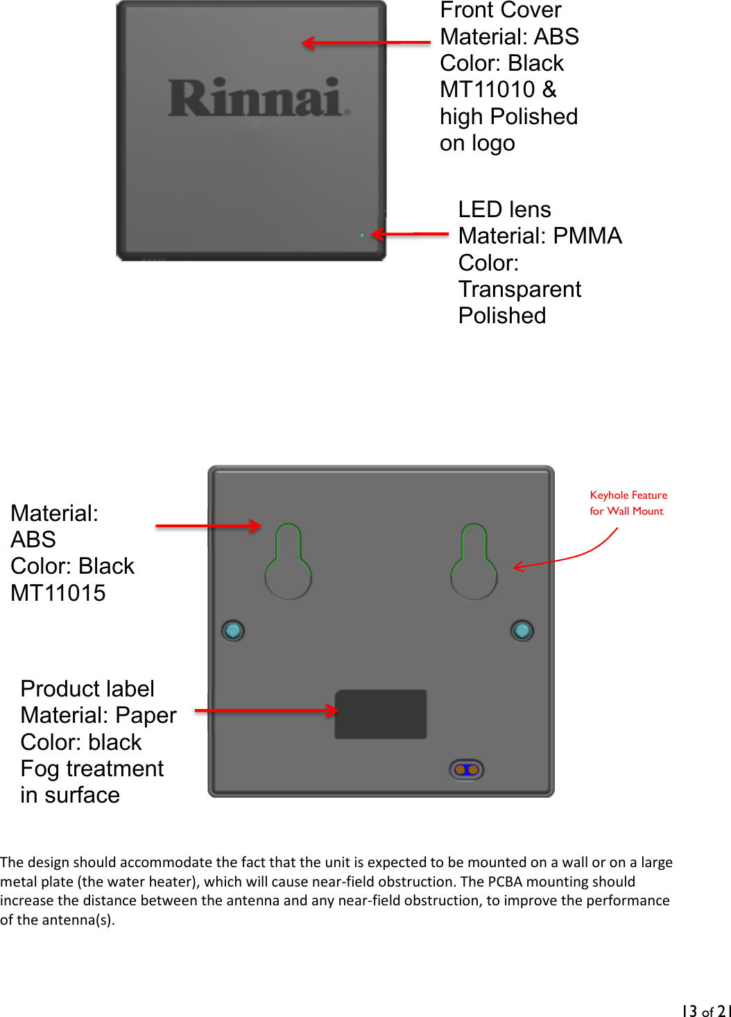
![14 of 21 6.1.2. CHEMICAL RESISTANCE The mechanical design shall demonstrate chemical resistance to short-term exposure to common household cleaning agents applied to the exterior of the product, as well as any substance commonly found on the human hand. [PR-018] 6.1.3. UV STABILITY UV resistance per ASTM 4674 Method 1: Delta E<1.4: Irradiance level of 2806 W-h/m2. No degradation of the material is allowed, but color changes are acceptable. In the event of a color change, the change shall result in a delta-E of 1.4 or less for HB for ABS material or 1.7 or less for PC material. [PR-019] 6.2. ENCLOSURE DESIGN SPECIFICATIONS The enclosure is a simple box structure consisting of a rear panel or base and a top or front cover with front face and side walls. The front face shall accommodate the Rinnai logo, as shown in the example ID, and the status LED as defined in section # 4.5.2 [PR-020] The top cover shall have holes/cutouts, as shown in the example ID, to accommodate the terminal block and the two buttons (Reset & WPS) defined in section # 4.5 6.3. REAR PANEL DESIGN SPECIFICATIONS The rear panel shall be designed with two key-hole slots for wall mounting, according to the keyhole dimensions shown below. The depth of the slot shall be 5mm and shall accommodate a screw head thickness of 3mm. The plastic design shall block direct access into the enclosure through the keyhole slot. The rear panel design shall also have design features to install one or more magnets, to enable the unit to be magnetically mounted on the water heater. [PR-021] 6.4. ENCLOSURE MECHANICAL DESIGN DETAILS The maximum enclosure dimensions and approximate weight shall be: [PR-022] • Width: 100 mm MAX • Length : 100 mm MAX • Thickness: 35 mm MAX • Weight: TBD lbs. MAX Note: all dimensions are approximate 6.5. THERMAL SPECIFICATIONS The operating and storage temperature ranges shall be: [PR-023] 8mm 4mm 14mm](https://usermanual.wiki/Rinnai-America/RWM101B/User-Guide-3074797-Page-14.png)
![15 of 21 • The Smart home gatewayshall be designed to operate without any performance degradation throughout the temperature range of the device. (0 to 40 deg. C) • Storage temperature shall be -10 to +60 deg. C 6.6. LABEL SPECIFICATIONS The mechanical design shall provide labeling areas as follows: [PR-024] • Product identification o Serial Number o MAC Address o Ayla DSN • Warnings o “Class-2 Low Voltage connection only” • Agency-required labels o FCC o IC 7. INDUSTRIAL DESIGN The industrial design of the S mart home gateway(ID) shall follow the example provided in section # 6.1.1 [PR-027] 8. ENVIRONMENTAL SPECIFICATIONS AND PARAMETERS This section describes the operational and non-operational environment the Smart home gateway shall be designed to operate in. For the purposes of this section, the following definitions apply: • Functional failure: Permanent loss of functionality or degradation in performance below specified limits, not including cosmetic failures. 8.1. OPERATIONAL ENVIRONMENTAL ENVELOPE [PR-028] Table 4 - Operational Environmental Envelope](https://usermanual.wiki/Rinnai-America/RWM101B/User-Guide-3074797-Page-15.png)
![16 of 21 Parameter Min Typical Max Unit Operating Temperature @ sea level1 @ max altitude 0 40 35 ⁰C Operating Humidity2 8 95 %RH Operating Altitude, relative to Mean Sea Level (MSL) 3100 M Operational Temperature Ramp 20 ⁰C/hr Notes: 1. Sea-level testing is performed at a nominal altitude of 0-300 m. 2. Non-condensing. Table 5 Operational Environment Envelope 8.2. NON-OPERATIONAL ENVIRONMENTAL ENVELOPE [PR-029] These specifications cover the product after it has been removed from its retail packaging. Table 6 - Storage Environment Specifications Parameter Min Max Unit Temperature (External ambient)1 -10 60 °C Temperature Ramp Rate2 10 °C/minute Relative Humidity3, 8 5 95 % Relative Humidity Ramp Rate4 30 %/hour Wet-Bulb Temperature5 40 °C Altitude, relative to Mean Sea Level (MSL)6 -382 (106) 13600 (15.0) m (kPa) Pressure Ramp Rate7 10 kPa/minute Notes: 1. These limits were derived from ETSI 300 019-2-7, T7.3 & SAE J1455. 2. This limit comes from ESTI 300 019-2-7, T7.3. 3. This limit comes from guidance found in IEC 60068-2-30 & previous testing experience. 4. This limit comes from information gathered in other electronic devices’ specifications. 5. This specification comes from ETSI 300 019-2-7, T7.3 and IEC 60068-2-13. 6. This limit is based upon guidance found in IEC 60068-2-13. Condensation is not permitted under any circumstances. Table 7 Non-Operational Environment Envelope 8.3. VERTICAL DROP CHASSIS ENDURANCE [PR-030] The Smart home gateway MUST be operational within specifications after being dropped once on any side without its shipping carton from a height of 75 cm onto a concrete floor. The Smart home gateway MUST NOT develop any openings or other deformations that could introduce the risk of an electrical shock. 8.4. CHASSIS IMPACT [PR-031]](https://usermanual.wiki/Rinnai-America/RWM101B/User-Guide-3074797-Page-16.png)
![17 of 21 The Smart home gateway MUST withstand a 1.3 meter (51 in) free-fall drop of a 51 mm (2 in) sphere weighing 535 grams (1.18 lb) resulting in an absence of distortion in the chassis that would create any contact between the chassis and an electrically active circuit, or expose any openings that would create a risk of electrical shock or high energy current levels. 8.5. CHASSIS STATIC LOAD [PR-032] The Smart home gateway chassis MUST NOT incur any damage or visible deformation after the Smart home gateway has been subjected to a static load of 45 kg for 1 minute without its shipping carton. 8.6. SHIPPING VIBRATION [PR-033] The Smart home gateway MUST be fully operational within specifications after exposure without its shipping carton to a swept frequency vibration applied in each of the three (3) mutually perpendicular planes with a peak displacement of 2.5 mm (5 mm total excursion) each side of resting point, in each plane. Note: The frequency of vibration will be varied uniformly from seven (7) to thirty (30) cycles and back to seven (7) cycles per second three (3) times over a period of thirty (30) minutes. 9. SYSTEM PERFORMANCE METRICS AND RELIABILITY 9.1. LONG-TERM STABILITY The Smart home gateway incorporates digital logic and multiple radio subsystems. As with any machine with similar performance, each piece of logic and each digital bus has a small, but finite probability of an error occurring. Since not all errors are trapped, there exists a small but finite probability that the system will crash if it runs long enough. This is a soft failure, since the user can reboot the device and it will operate normally, hence this metric is expressed as a Mean Time Between Failures or MTBF. Long-term stability is defined as the capability of Smart home gateway to operate continuously, without crashing, for extended periods of time. Since crashes are probabilistic by nature, this metric shall be defined as the reciprocal of the number of random crashes occurring per device hour of operation. For purposes of this test, an application that taxes all major subsystems of the device shall be run continuously on a population of devices for an extended period of time. In service MTBF calculations MUST be in hours as per the following formula: MH = TT / TF Where: MH = Mean Time Between Failures in Hours TT = Cumulative service hours TF = Total Failures during TT](https://usermanual.wiki/Rinnai-America/RWM101B/User-Guide-3074797-Page-17.png)
![18 of 21 The Smart home gateway Annualized Failure Rate ( AFR) MUST NOT exceed 2% of the installed units per current year. • MTBF of 438,000 hours @ 25 °C [PR-034] • MTBF of 100,000 hours @ 50 °C. [PR-035] The Smart home gateway MUST NOT exceed 2% failure rate over the projected service life of the products of 5 years during any period and quantity of units over any interval analyzed. [PR-036] 9.2. LIST OF CRITICAL COMPONENTS In order to maintain high levels of product reliability, the quality and function of certain components is critical. In addition, some components impact safety and EMI certifications. Deviation from the AML for critical components cannot be made without engineering approval. The list of components is as follows: 1. Main Processor and WiFi Module 2. ZigBee Transceiver 3. Rinnai custom Murata chip H8D3317 4. Rinnai customized Renesas microprocessor R5F101JEDFA 5. DDR Memory 6. Flash Memory 7. Power Supply Regulators 8. Connector 10. AGENCY AND INDUSTRY CONFORMANCE REQUIREMENTS 10.1. SAFETY COMPLIANCE The external power supply in the water heater used to power the App Enablement Module shall comply with the agency requirements of: (as a minimum) [PR-037] 1. ANSI Z21.10.3CSA 4.3 10.2. SYSTEM IMMUNITY The App Enablement Module shall comply with ESD immunity test per ETSI /ESD standard. [PR-038] 10.3. EMI COMPLIANCE The App Enablement Module shall be designed to comply with the EMI standards listed below, for unintentional emissions. [PR-039] The device shall fulfill the requirements of: • (IC) Industry Canada Interference-Causing Equipment Standard ICES-003 • FCC part 15 class B for unintentional emissions (Residential)](https://usermanual.wiki/Rinnai-America/RWM101B/User-Guide-3074797-Page-18.png)
![19 of 21 • (FCC) 47 CFR 15, ‘Title 47 – Telecommunication. Chapter I – Federal Communications Commission. Part 15 - Radio frequency devices’, Class B for ZigBee and WiFi intentional emissions. 10.4. ROHS COMPLIANCE The Smart home gateway shall meet the EU directive for removal of hazardous substances (RoHS) as shown in the following table: [PR-040] Item Region Requirement Standard 1 EU NA Environmental Materials & Process RoHS Certificates of Compliance Reduction of Hazardous Substances Directive 2002/95/EC of the European Parliament and Council of 27-Jan-2003 2 EU NA Materials Recycling Documented WEEE System and Processes Waste Electrical & Electronic Equipment Directive 2002/96/EC, Table 8 RoHS Compliance 11. SUMMARY OF TECHNICAL HARDWARE SPECIFICATIONS The following tables provide a convenient summary of the product technical specifications for the Smart home gateway and a compliance matrix to validate specifications have been met. 11.1. UNIT ARCHITECTURE COMPLIANCE MATRIX PRD. Number Specification MRD Compliance [PR-001] The main processor shall be a MIPS 24KEc embedded within the MediaTek MT7620A SoC [PR-002] The following radios Shown in table 3.1.2 will be used in the Smart home gateway [PR-003] WiFi module shall be based on the MediaTek MT7620A integrated radio chipset [PR-004] The Zigbee radio shall utilize the Silicon Labs EM357 transceiver [PR-005] PCB design practices compliant with section 4.1 [PR-006] Onboard power supply design compliant with section 4.2 [PR-007] Processor must support clock speed up to 580MHz [PR-008] Unit designed for 256MB / 128MB / 64MB of DDR2 RAM [PR-009] Unit designed for 128MB of NAND flash [PR-010] Headers / other mechanisms provided to program all programmable parts](https://usermanual.wiki/Rinnai-America/RWM101B/User-Guide-3074797-Page-19.png)
![20 of 21 [PR-011] External connectors, buttons & indicators provided per table 4.5 [PR-012] LED indicators provided and function per table 4.5.2 [PR-013] User button for WiFi setup per 4.5.3 [PR-014] User button for input to SoC per 4.5.4 [PR-015] Antenna types compliant with section 5 [PR-016] Antenna performance will be optimized by simulation [PR-017] Both wall and heater mounting supported [PR-018] Unit enclosure resistant to household chemicals [PR-019] Unit enclosure is UV stable per section specifications [PR-020] Front panel will accommodate LEDs [PR-021] Enclosure shall have keyhole slots and magnetic mounting features per section 6.3 [PR-022] Enclosure dimensions shall comply with section 6.4 [PR-023] Unit meets thermal specifications in section 6.5 [PR-024] Labels will be provided per section 6.6 [PR-025] Enclosure logos provided per section 6.7 [PR-026] Board dimensions compliant with section 6.8 [PR-027] Industrial design per section 6.1.1 [PR-028] Operational environmental envelope compliant with section 8.1 [PR-029] Storage environmental envelope compliant with section 8.2 [PR-030] Vertical Drop Chassis Endurance specifications in Section 8.3 [PR-031] Chassis Impact specifications in Section 8.4 [PR-032] Chassis Static Load specifications in Section 8.5 [PR-033] Shipping Vibration specification in Section 8.6 [PR-034] MTBF of 438,000 hours @ 25 °C in Section 9.1 [PR-035] MTBF of 100,000 hours @ 50 °C in Section 9.1 [PR-036] Failure Rate MUST NOT exceed 2% failure rate over 5 years in Section 9.1 [PR-037] External power supply will meet UL and CSA safety standards [PR-038] Unit will meet ESD immunity per ETSI specifications [PR-039] Unit will meet applicable FCC and CSA EMI standards [PR-040] Unit will be designed for RoHS compliance Table 9 Requirement Compliance Matrix](https://usermanual.wiki/Rinnai-America/RWM101B/User-Guide-3074797-Page-20.png)