Rockwell Collins 8221468 Dual Channel Spacing Aeronautical Transceiver User Manual Production Test Requirements
Rockwell Collins Inc Dual Channel Spacing Aeronautical Transceiver Production Test Requirements
Contents
- 1. Users Manual
- 2. Production Test Requirements
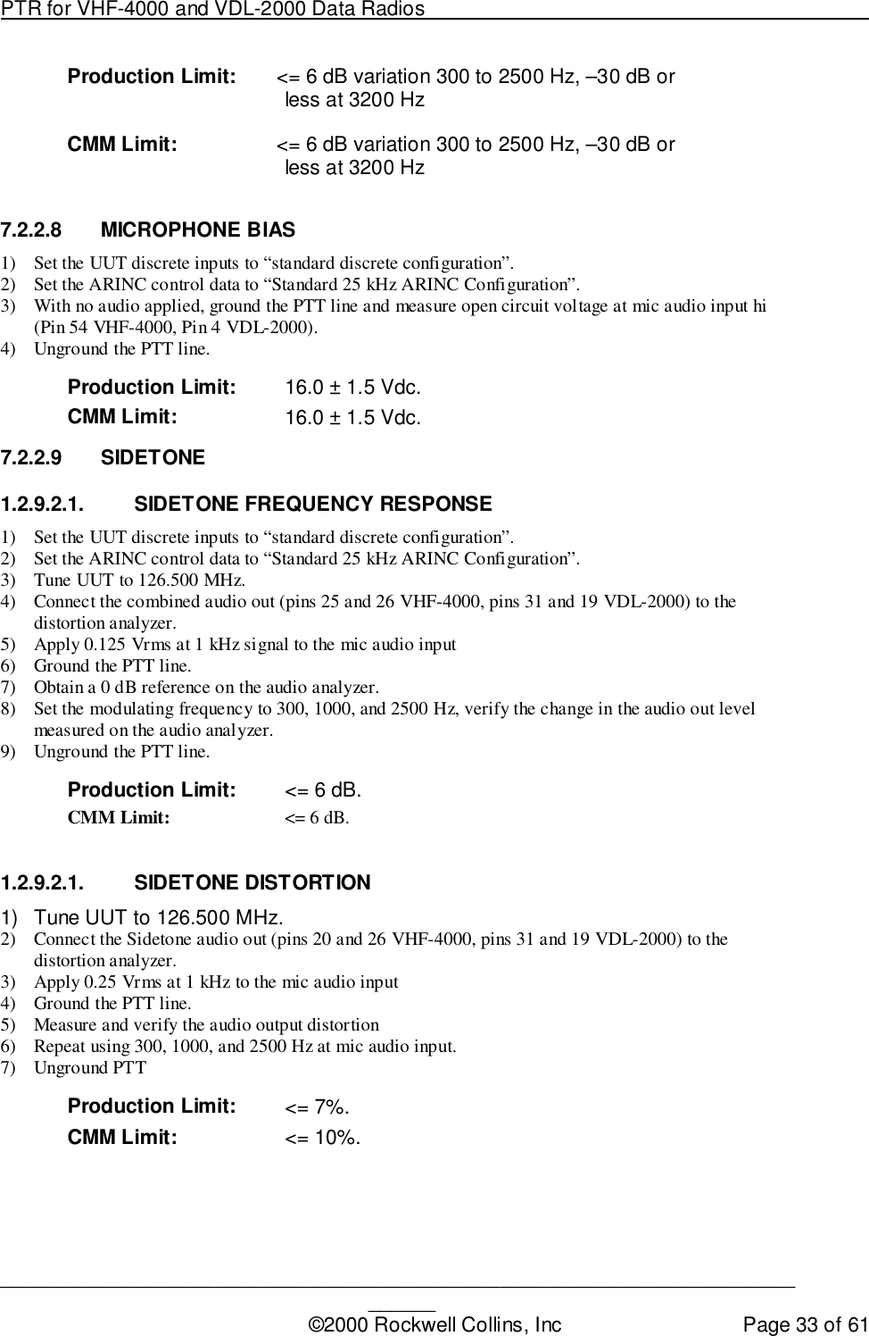
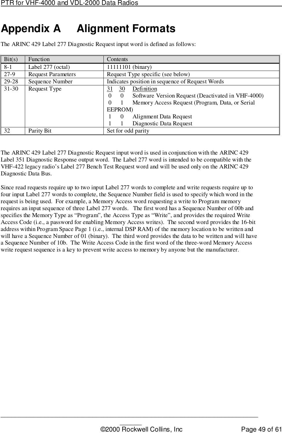
Production Test Requirements
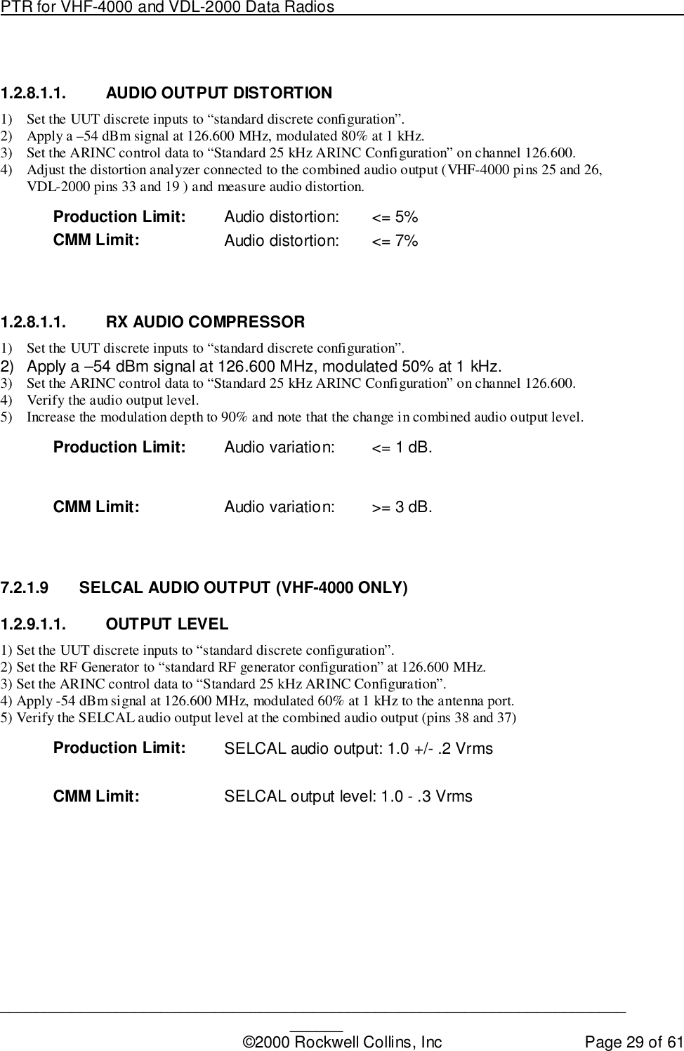
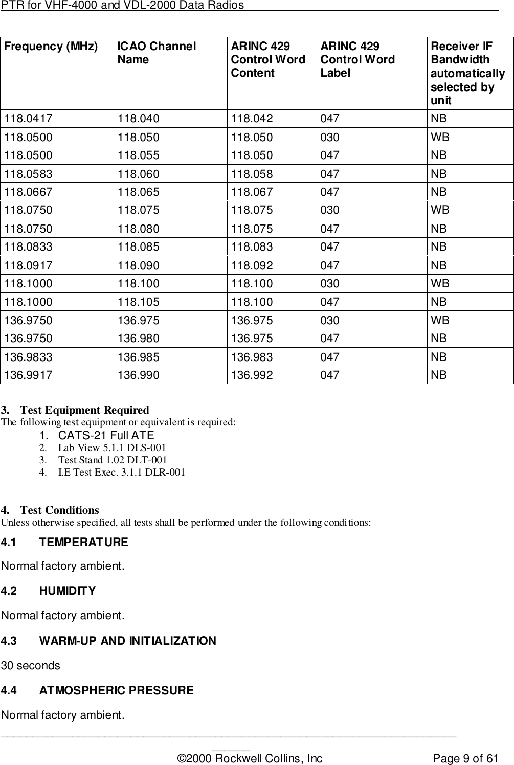
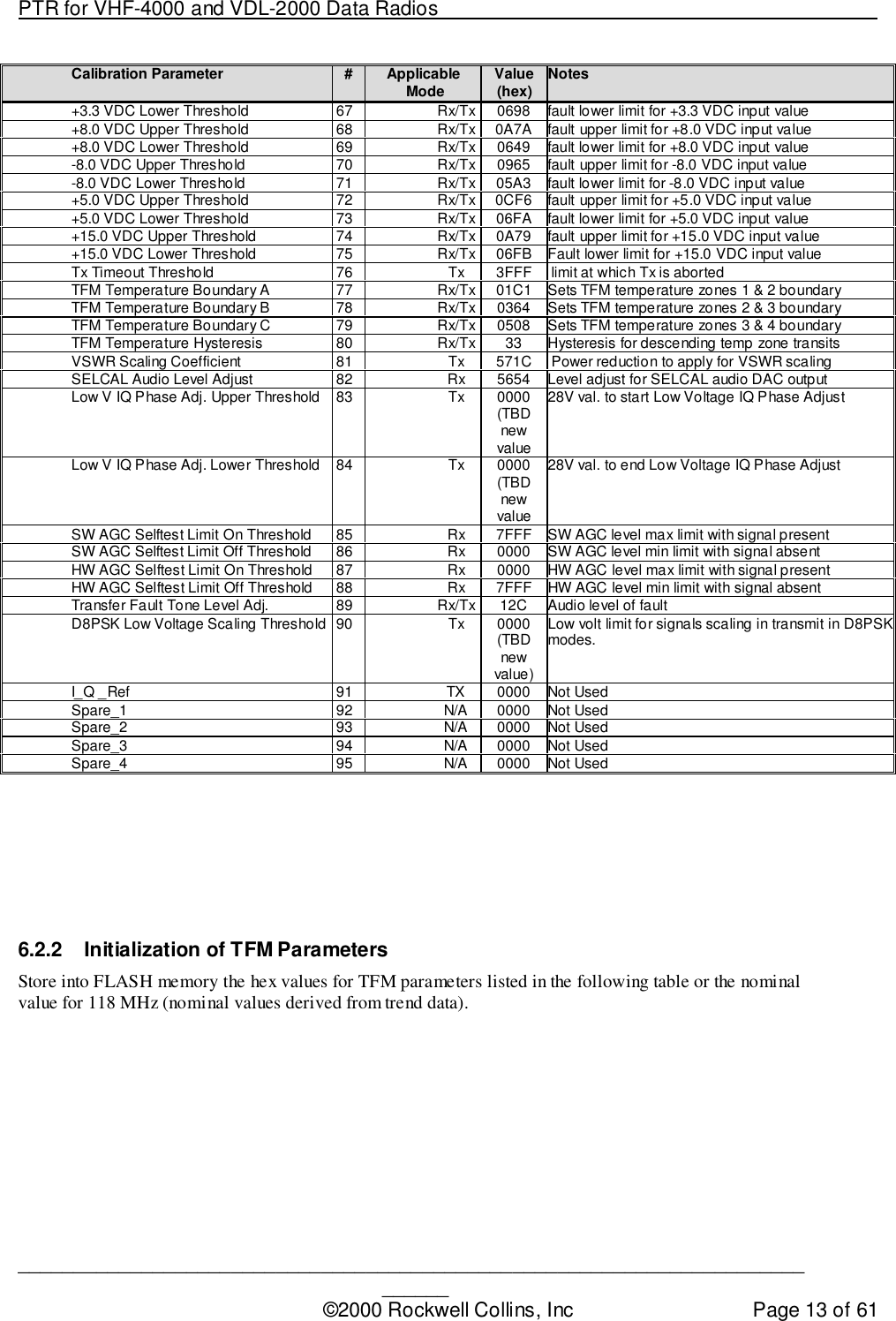
![PTR for VHF-4000 and VDL-2000 Data Radios ____________________________________________________________________________©2000 Rockwell Collins, Inc Page 5 of 61TABLE OF CONTENTSNotices and Signatures ................................................................................................................... 2Revision History .............................................................................................................................. 3Review History................................................................................................................................. 4TABLE OF CONTENTS.................................................................................................................. 51. Scope........................................................................................................................................ 82. Reference Information.............................................................................................................. 82.1 Specifications..................................................................................................................... 82.2 Drawings ............................................................................................................................ 82.2.1 VHF-4000 .................................................................................................................... 82.2.2 VDL-2000..................................................................................................................... 82.3 Operating Frequencies VS ICAO Channel Designators ................................................... 83. Test Equipment Required......................................................................................................... 94. Test Conditions......................................................................................................................... 94.1 Temperature....................................................................................................................... 94.2 Humidity ............................................................................................................................. 94.3 Warm-up and Initialization ................................................................................................. 94.4 Atmospheric Pressure........................................................................................................ 94.5 Transmit Duty Cycle......................................................................................................... 105. Test Definitions and Information............................................................................................. 105.1 Standard Discrete Configuration...................................................................................... 105.2 Standard RF Generator Configuration............................................................................. 105.3 Standard ARINC 429 Bus/Data Configurations............................................................... 115.3.1 Standard Control Data Configurations...................................................................... 115.3.2 Standard Data Configurations................................................................................... 115.4 Test Sequence................................................................................................................. 116. Alignment................................................................................................................................ 126.1 Software Load Procedure ................................................................................................ 126.2 Calibration and TFM Parameters..................................................................................... 126.2.1 Initialization of Calibration Parameters ..................................................................... 126.2.2 Initialization of TFM Parameters ............................................................................... 136.3 Alignment Procedures...................................................................................................... 146.3.1 Receiver Analog Audio Output Level (VHF4000 Only) [Rx Cal] .............................. 146.3.2 Selcal Audio Output Level (VHF4000 Only) [Rx Cal] ............................................... 156.3.3 Voice Carrier Null [Tx TFM]....................................................................................... 156.3.4 Voice/Analog Data Bias Adjustment [Tx TFM] ......................................................... 156.3.5 +28 V Transmitter Phasing Adjustment [Tx TFM] .................................................... 156.3.6 +20 V Transmitter Phasing Adjustment [Tx TFM] .................................................... 166.3.7 Preselector Adjustments [Rx Cal] ............................................................................. 166.3.8 Analog Voice/Data Unmodulated Transmitter RF Power [Tx TFM] ......................... 166.3.9 Simulcomm 0 Adjustment (-20 dBm threshold) [Rx TFM]........................................ 176.3.10 Simulcomm 1 Adjustment (-10 dBm threshold) [Rx TFM]........................................ 176.3.11 Analog Voice/Data Transmitter Modulation [Tx TFM] .............................................. 176.3.12 Simulcomm 2 Adjustment ( 0 dBm threshold) [Rx TFM].......................................... 176.3.13 Analog and Digital Sidetone Levels [Tx Cal]............................................................. 18](https://usermanual.wiki/Rockwell-Collins/8221468.Production-Test-Requirements/User-Guide-183937-Page-5.png)
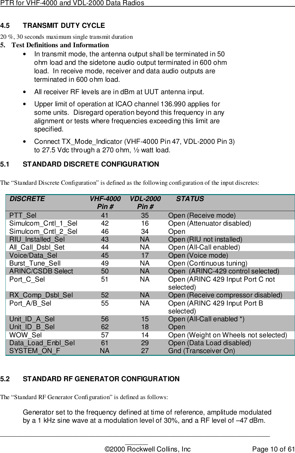
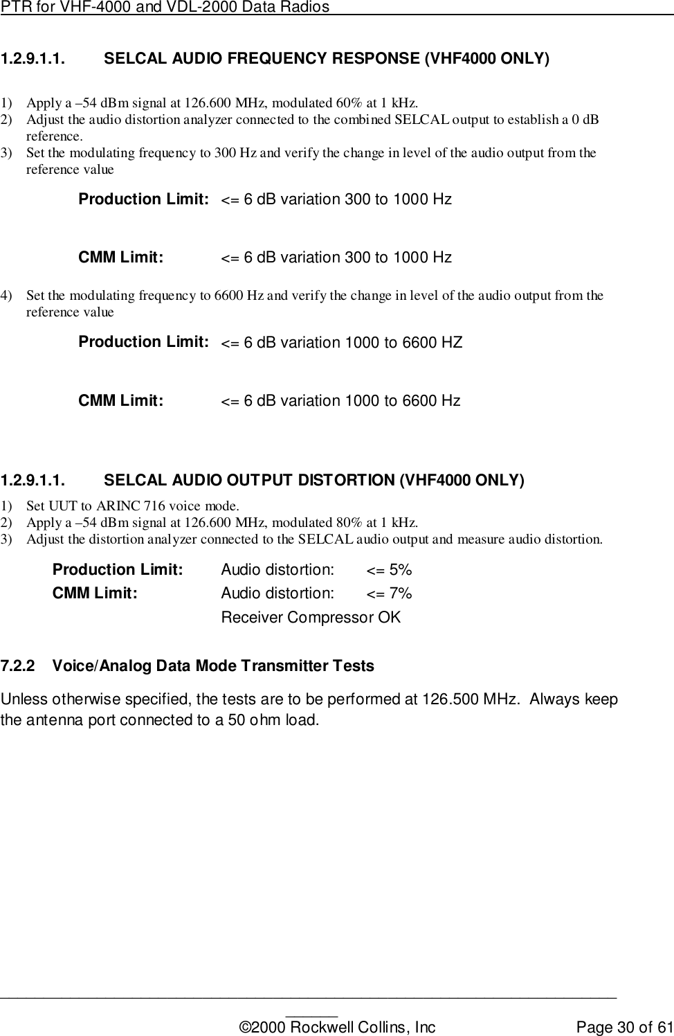
![PTR for VHF-4000 and VDL-2000 Data Radios ____________________________________________________________________________©2000 Rockwell Collins, Inc Page 14 of 61TFM Parameter #Applicable Mode Value(hex) NotesI Phase Adjust 1 Tx 0000 normal setting for I phase adjustment DACsQ Phase Adjust 2 Tx 2048 normal setting for Q phase adjustment DACsSimulcomm 0 3 Rx FF sets SCOM Thresh DAC when Simulcomm discretes= 00Simulcomm 1 4 Rx FF sets SCOM Thresh DAC when Simulcomm discretes= 01Simulcomm 2 5 Rx FF sets SCOM Thresh DAC when Simulcomm discretes= 10Simulcomm 3 6 Rx FF sets SCOM Thresh DAC when Simulcomm discretes= 11Preselector 1 7 Rx/Tx 0000 sets Presel_1 DACPreselector 2 8 Rx/Tx 0000 sets Presel_2 DACPreselector 3 9 Rx/Tx 0000 sets Presel_3 DACPreselector 4 10 Rx/Tx 0000 sets Presel_4 DACPA Drive Bias for D8PSK 11 Rx/Tx 0000 sets PA Drive Bias DAC when in ARINC 750 Mode 2PA Drive Bias for all but D8PSK 12 Rx/Tx 0000 sets PA Drive Bias DAC when not in ARINC 750Mode 2PA Final Bias for D8PSK 13 Rx/Tx 0000 sets PA Final Bias DAC when in ARINC 750 Mode 2PA Final Bias for all but D8PSK 14 Rx/Tx 0000 sets PA Final Bias DAC when not in ARINC 750Mode 2D8PSK I Channel Gain 15 Tx 0000 sets I channel gain for D8PSK transmissionsD8PSK Q Channel Gain 16 Tx 0000 sets Q channel gain for D8PSK transmissionsAM I Channel Carrier Power 17 Tx 0000 sets I channel offset (carrier power) for AMtransmissionsAM Q Channel Carrier Power 18 Tx 0000 sets Q channel offset (carrier power) for AMtransmissionsD8PSK I Channel Carrier Null (offset) 19 Tx 0000 sets I channel offset (carrier null) for D8PSKtransmissionsD8PSK Q Channel Carrier Null (offset) 20 Tx 0000 sets Q channel offset (carrier null) for D8PSKtransmissionsMode A I Channel Carrier Power(offset) 21 Tx 0000 sets I channel offset (carrier power) for Mode Atransmissions Mode A Q Channel Carrier Power(offset) 22 Tx 0000 sets Q channel offset (carrier power) for Mode AtransmissionsAM I Channel Mod % (gain) 23 Tx 0000 Sets I channel mod % (gain) for AM TxAM Q Channel Mod % (gain) 24 Tx 0000 Sets Q channel mod % (gain) for AM transmissionsMode A I Channel Mod % (gain) 25 Tx 0000 Sets I channel mod % (gain) for Mode AtransmissionsMode A Q Channel Mod % (gain) 26 Tx 0000 Sets Q channel mod % (gain) for Mode AtransmissionsAM Voice Rx Audio Phase Shift 27 Rx 0000 Adjusts phase of Rx audio output relative to input RFmodulationD8PSK Quadrature Mismatch 28 Tx 0000 compensates transmit signal for feedback modulatormismatchRx Synthesizer Adjust 29 Rx 55 CN count for receiver synthesizer tuningTx Synthesizer Adjust 30 Tx 8C CN count for transmitter synthesizer tuningI Low Voltage Phase Adjust 31 Tx 0000 normal setting for I phase adjustment DACsQ Low Voltage Phase Adjust 32 Tx 07FF normal setting for Q phase adjustment DACsMode 2 –90.5 dBm Level 33 Rx normal setting for –90.5 dBm Mode 2 Rx levelMode 2 –91.5 dBm Level 34 Rx normal setting for –91.5 dBm Mode 2 Rx levelAM I Channel Carrier Null (offset) 35 Tx 07FF sets I channel offset null for AM transmissionsAM Q Channel Carrier Null (offset) 36 Tx 07FF sets Q channel offset null for AM transmissionsSpur Suppression Noise Level 37 Tx 8.3 kHz synthesizer spur adj.Spare 6 38 N/ASpare 7 39 N/ASpare 8 40 N/ASpare 9 41 N/ASpare 10 42 N/A6.3 ALIGNMENT PROCEDURES6.3.1 Receiver Analog Audio Output Level (VHF4000 Only) [Rx Cal]1) Set Standard ARINC Configuration at 118.5 MHz.](https://usermanual.wiki/Rockwell-Collins/8221468.Production-Test-Requirements/User-Guide-183937-Page-14.png)
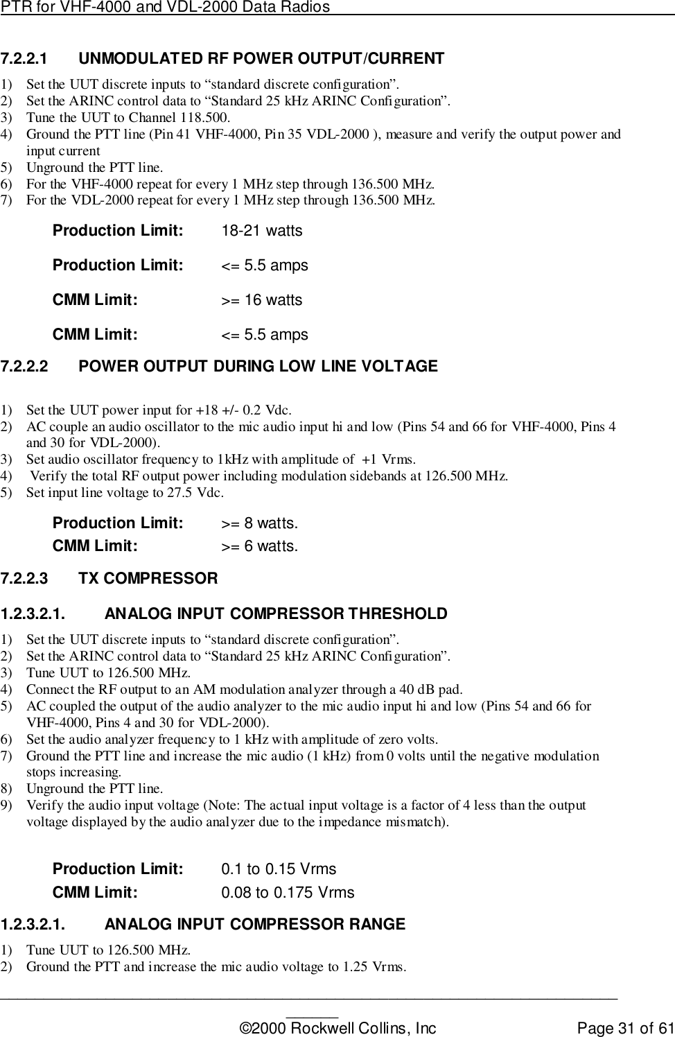
![PTR for VHF-4000 and VDL-2000 Data Radios ____________________________________________________________________________©2000 Rockwell Collins, Inc Page 15 of 612) Set Standard RF Generator Setting at 118.5 MHz.3) Set Standard Discrete Configuration.4) Set the generator to 85% modulation and -40 dBm RF level.5) Monitor the receiver audio output and adjust calibration parameter #1 (Combinedaudio level adjust) for 7.75 Vrms ± 0.1 Vrms.6) Store the values used for calibration parameters #1, 2, and 40 in Flash memory.6.3.2 Selcal Audio Output Level (VHF4000 Only) [Rx Cal]1) Set Standard ARINC Configuration at current frequency.2) Set Standard RF Generator setting at current frequency.3) Set Standard Discrete Configuration.4) Set the generator to 60% modulation and -40 dBm RF level.5) Monitor the SELCAL audio output and adjust calibration parameter #40 (SELCALaudio) for 500 mVrms ± 25 mVrms.6) Store the values used for calibration parameters #1, 2, and 40 in Flash memory.6.3.3 Voice Carrier Null [Tx TFM]1) Set Standard ARINC Configuration at current frequency.2) Set Standard Discrete Configuration.3) Set the ARINC data to “Standard 25 kHz ARINC Configuration” on channel 118.500.4) Connect 50 ohm load to antenna cable.5) Ground the PTT (Pin 41), Monitor RF Transmitter power.6) Simultaneously vary TFM parameters # 35 and # 36 (AM I and Q channel offset) toget lowest possible power output. The null power out must be less than 4 dBm.7) Unground the PTT.6.3.4 Voice/Analog Data Bias Adjustment [Tx TFM]1) Set Standard ARINC Configuration at current frequency.2) Set Standard Discrete Configuration.3) Set the ARINC data to “Standard 25 kHz ARINC Configuration” on channel 118.500.4) Connect 50 ohm load to antenna cable.5) Set TFM parameters #12 and #14 (PA drive bias and final driver bias) to $0000.6) Ground the PTT (Pin 41), and monitor the input current to the UUT.7) Adjust TFM parameter #14 until the current increases by 1500 ma ± 50 ma over theoriginal value.8) Adjust TFM parameter #12 until the current increases by an additional 500 ma ± 50ma over the value in step 8.9) Unground the PTT.10) Store the values used for TFM parameters #12 and #14 in the Flash memorylocation for all temperature zones and channels.11) Find values only at 118 MHz channel, use that value for all other channels.6.3.5 +28 V Transmitter Phasing Adjustment [Tx TFM]1) Set Standard ARINC Configuration at current frequency.2) Set Standard Discrete Configuration.3) Verify power supply input voltage is 27.5 +/- 0.2 Vdc.4) Apply 0.7 Vrms, 1 kHz tone to Microphone Audio input.5) Set I & Q channel carrier offset to 06) Set Q Channel Gain to 0.7) Set I Channel Gain to get 4 – 6 watts RF output power8) Monitor the Q_Detector Output of the RF Card](https://usermanual.wiki/Rockwell-Collins/8221468.Production-Test-Requirements/User-Guide-183937-Page-15.png)
![PTR for VHF-4000 and VDL-2000 Data Radios ____________________________________________________________________________©2000 Rockwell Collins, Inc Page 16 of 619) Ground the PTT and vary TFM parameter #1 & #2 (Q phase & I adjust) up or downfrom initial value as necessary to null the Q detector voltmeter reading. Final valuemust be less than TBD.Note: The I& Q Phase Adjust values are calculated as a function of the phase angleusing the following formula:Q bits = ((1.25 x sine (Angle) + 1.25)) / (2.5/4095)I bits = ((1.25 x cos (Angle) + 1.25)) / (2.5/4095)10) Unground the PTT.11) Store the values for TFM parameter #1 and #2 in Flash memory.6.3.6 +20 V Transmitter Phasing Adjustment [Tx TFM]1) Set Standard ARINC Configuration at current frequency.2) Set Standard Discrete Configuration.3) Verify power supply input voltage is 20.0 +/- 0.2 Vdc.4) Apply 0.7 Vrms, 1 kHz tone to Microphone Audio input.5) Set I & Q channel carrier offset to 06) Set Q Channel Gain to 0.7) Set I Channel Gain to get 4 – 6 watts RF output power8) Monitor the Q_Detector Output of the RF Card9) Ground the PTT and vary TFM parameter #30 & #31 (LV Q phase & I adjust) up ordown from initial value as necessary to null the Q detector voltmeter reading. Finalvalue must be less than TBD.Note: The I& Q Phase Adjust values are calculated as a function of the phase angleusing the following formula:Q bits = ((1.25 x sine (Angle) + 1.25)) / (2.5/4095)I bits = ((1.25 x cos (Angle) + 1.25)) / (2.5/4095)10) Unground the PTT.11) Store the values for TFM parameter #1 and #2 in Flash memory.6.3.7 Preselector Adjustments [Rx Cal]1) Set Standard ARINC Configuration at current frequency.2) Set Standard RF Generator setting at current frequency.3) Set Standard Discrete Configuration.4) Monitor the combined audio output.5) Adjust the generator RF level to give approximately 12 dB SINAD ratio.6) Iteratively adjust TFM parameters #7 –10 from initial values for the best SINAD while reducing theRF level to maintain 12 dB SINAD. The final SINAD after adjustment must be at least 8 dB with –103 dBm input RF level.7) Store the values used for TFM parameters #7 - #10 in Flash memory.6.3.8 Analog Voice/Data Unmodulated Transmitter RF Power [Tx TFM]1) Set Standard ARINC Configuration at current frequency.2) Set Standard Discrete Configuration.3) Set TFM parameters #17 & #18 (AM I and Q channel carrier power) to 2048 (Dec).4) Ground the PTT and increment TFM parameters # 17 until the RF wattmeterindicates 10 watts +/- 1 watt.](https://usermanual.wiki/Rockwell-Collins/8221468.Production-Test-Requirements/User-Guide-183937-Page-16.png)
![PTR for VHF-4000 and VDL-2000 Data Radios ____________________________________________________________________________©2000 Rockwell Collins, Inc Page 17 of 615) Increment TFM parameters # 18 until the RF wattmeter indicates 19.5 watts +/- 1watt.6) Unground the PTT.7) Store the values for TFM parameters #17 and 18 in Flash memory.6.3.9 Simulcomm 0 Adjustment (-20 dBm threshold) [Rx TFM]1) Set Standard ARINC Configuration at current frequency.2) Set Standard RF Generator setting at current frequency.3) Set Standard Discrete Configuration.4) Set rear connector simulcomm discretes to 00 (VHF4000 Pins 42 and 46 open, VDLPins 16 and 34 open).5) Set the generator RF level to -20 dBm and 90% modulation.6) Monitor the AGC_Level output of the RF Card.7) Decrease TFM parameter # 3 until the AGC_Level decreases at least 2% - 4% fromthe reading in step 6.8) Store the value used for TFM variable #3 in the Flash memory.9) Find value at 118 MHz channel and use value for 119-125 MHz channels.10) Find value at 126 MHz channel and use value for 127-136 MHz channels.6.3.10 Simulcomm 1 Adjustment (-10 dBm threshold) [Rx TFM]1) Set Standard ARINC Configuration at current frequency.2) Set Standard RF Generator setting at current frequency.3) Set Standard Discrete Configuration.4) Set rear connector simulcomm discretes to 01(VHF4000 Pins 42 open and 46ground, VDL Pins 16 open and 34 ground).5) Set the generator RF level to -10 dBm and 90% modulation.6) Monitor the AGC_Level output of the RF Card.7) Decrease TFM parameter # 4 until the AGC_Level decreases at least 2% - 4% fromthe reading in step 6.8) Store the value used for TFM variable #4 in the Flash memory.9) Find value at 118 MHz channel and use value for 119-125 MHz channels.10) Find value at 126 MHz channel and use value for 127-136 MHz channels.6.3.11 Analog Voice/Data Transmitter Modulation [Tx TFM]1) Set Standard ARINC Configuration at current frequency.2) Set Standard Discrete Configuration.3) Apply a 0.4 Vrms audio signal at 1.0 kHz to the microphone input.4) Ground the PTT and simultaneously increment TFM parameters #23 and 24 (AM Iand Q Channel Mod) to obtain modulation of the negative peaks at 90 +/- 3 %.5) Unground the PTT.6) Store the value used for TFM parameters #23 and #24 in the Flash memory.6.3.12 Simulcomm 2 Adjustment ( 0 dBm threshold) [Rx TFM]1) Set Standard ARINC Configuration at current frequency.2) Set Standard RF Generator Setting at current frequency.3) Set Standard Discrete Configuration.4) Set rear connector simulcomm discretes to 10 (VHF4000 Pins 42 ground and 46open, VDL Pins 16 open and 34 ground).5) Set the generator RF level to 0 dBm and 90% modulation.6) Monitor the AGC_Level output of the RF Card.](https://usermanual.wiki/Rockwell-Collins/8221468.Production-Test-Requirements/User-Guide-183937-Page-17.png)
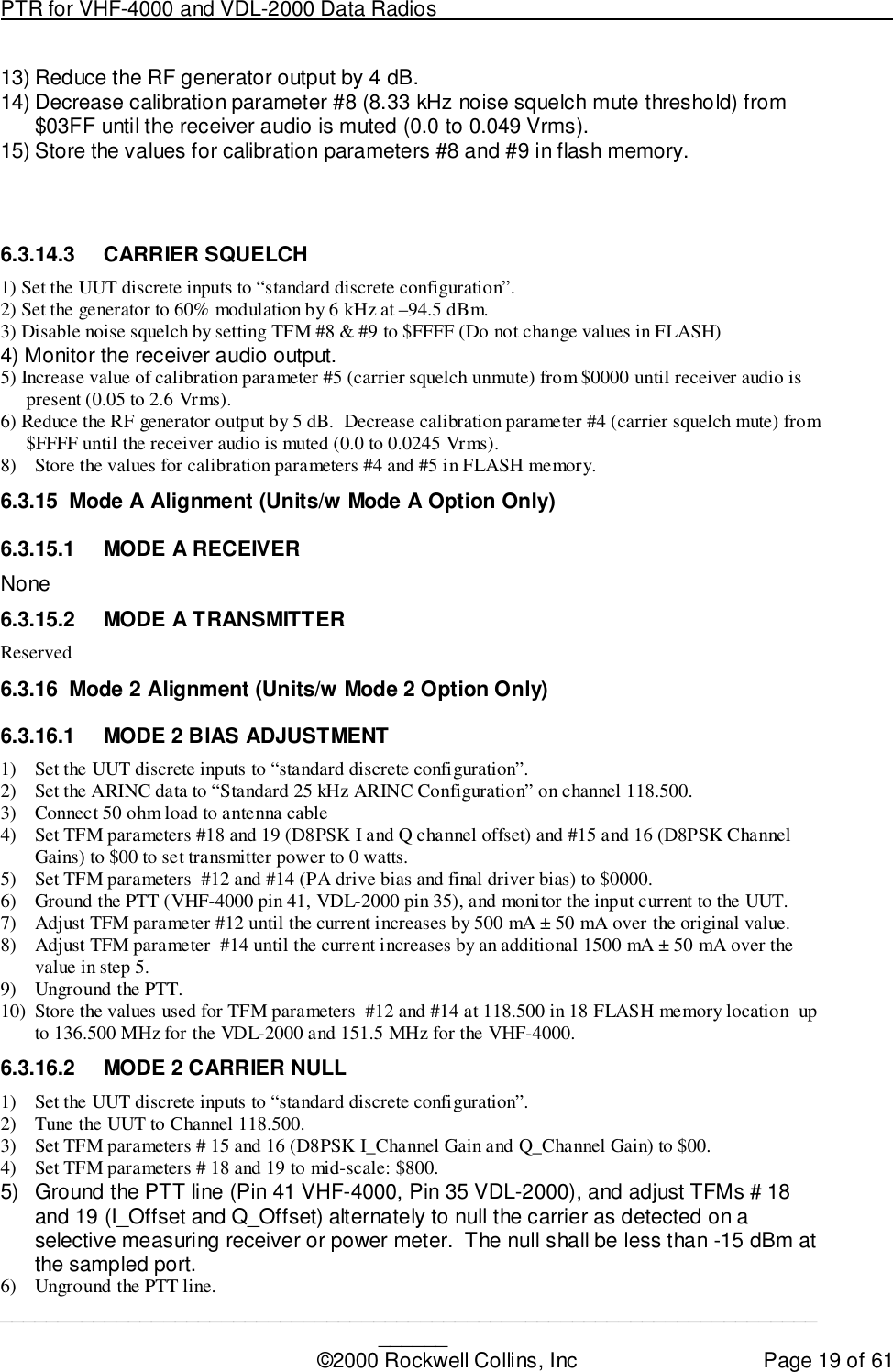
![PTR for VHF-4000 and VDL-2000 Data Radios ____________________________________________________________________________©2000 Rockwell Collins, Inc Page 18 of 617) Decrease TFM parameter # 5 until the AGC_Level decreases at least 2% - 4% fromthe reading in step 6.8) Store the value used for TFM variable #5 in the Flash memory.9) Find value at 118 MHz channel and use value for 119-125 MHz channels.10) Find value at 126 MHz channel and use value for 127-136 MHz channels.6.3.13 Analog and Digital Sidetone Levels [Tx Cal]1) Set Standard ARINC Configuration at 126.500 MHz.2) Set Standard Discrete Configuration.3) Apply a 0.4 Vrms audio signal to the microphone input.4) Ground the PTT and monitor the combined receiver audio output.5) Adjust calibration parameter #13 (combined sidetone level adjust) for 3.87 ± 0.1Vrms.6) Unground the PTT.7) Store the value calibration parameter # 12 and 13 in Flash memory.6.3.14 Squelch Adjustment6.3.14.1 25 KHZ NOISE QUIETING SQUELCH [RX CAL]1) Set Standard ARINC Configuration at current frequency.2) Set Standard RF Generator Setting at current frequency.3) Set Standard Discrete Configuration.4) Enable squelch on the ARINC tune word.5) Set Cal Parameter #4 (Carrier Squelch Mute Threshold) to 4000.6) Set Cal Parameter #5 (Carrier Squelch Unmute Threshold) to 0.7) Set Cal Parameter #6 (25kHz Noise Squelch Mute Threshold) to 0.8) Set Cal Parameter #7 (25kHz Noise Squelch Unmute Threshold) to 0.9) Set Cal Parameter #6 (25kHz Noise Squelch Mute Threshold) to 4000.10) Set the generator RF level to –103.5 dBm.11) Monitor the receiver audio output.12) Increase the value of calibration parameter #7 (25 kHz noise squelch unmute) from$0000 until receiver audio is present (0.05 to 2.6 Vrms).13) Reduce the RF generator output by 3 dB.14) Decrease calibration parameter #6 (25 kHz noise squelch mute) from $03FF until thereceiver audio is muted (0.0 to 0.0245 Vrms).15) Store the values for calibration parameters #6 and #7 in flash memory.6.3.14.2 8.33 KHZ NOISE QUIETING SQUELCH [RX CAL]1) Set Standard ARINC Configuration at current frequency.2) Set Standard RF Generator Setting at current frequency.3) Set Standard Discrete Configuration.4) Enable squelch on the ARINC tune word.5) Set Cal Parameter #4 (Carrier Squelch Mute Threshold) to 4000.6) Set Cal Parameter #5 (Carrier Squelch Unmute Threshold) to 0.7) Set Cal Parameter #8 (8.33kHz Noise Squelch Mute Threshold) to 0.8) Set Cal Parameter #9 (8.33kHz Noise Squelch Unmute Threshold) to 0.9) Set Cal Parameter #8 (8.33kHz Noise Squelch Mute Threshold) to 4000.10) Set the generator RF level to -104 dBm.11) Monitor the receiver audio output.12) Increase value of calibration parameter #9 (8.33 kHz noise squelch unmute) from$0000 until receiver audio is present (0.05 to 2.6 Vrms).](https://usermanual.wiki/Rockwell-Collins/8221468.Production-Test-Requirements/User-Guide-183937-Page-18.png)
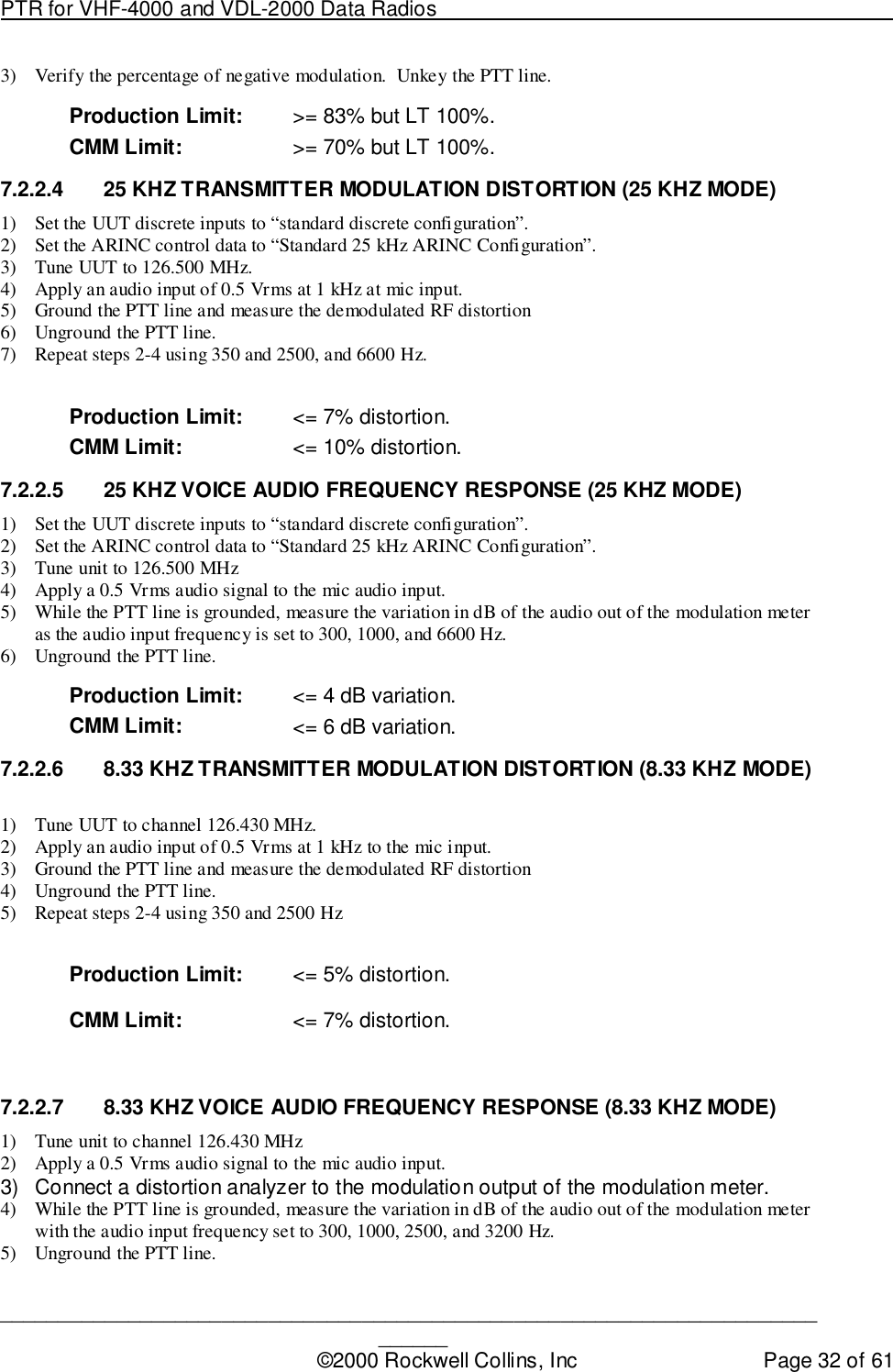
![PTR for VHF-4000 and VDL-2000 Data Radios ____________________________________________________________________________©2000 Rockwell Collins, Inc Page 24 of 611.2.2.1.1. SENSITIVITY 8.3 KHZ MODE CHANNEL 126.0051) Set the RF Generator frequency to 126.000 MHz.2) Set the ARINC control data to “Standard 8.33 kHz ARINC Configuration” on channel 126.005.3) Verify the S+N/N ratio at the combined audio output.Production Limit: 14.25 +/- 5.75 dB7.2.1.3 SENSITIVITY DURING LOW LINE VOLTAGE [ENTRY]1.2.3.1.1. SENSITIVITY DURING LOW LINE VOLTAGE CHANNEL 118.0001) Set the UUT power input for +18 ± 0.2 Vdc.2) Set the UUT discrete inputs to “standard discrete configuration”.3) Set the RF Generator to “standard RF generator configuration” at 118.000 MHz.4) Set the ARINC control data to “Standard 25 kHz ARINC Configuration” on channel 118.000 MHz.5) Set the RF generator output level to –103.5 dBm.6) Verify the S+N/N ratio at the combined audio output.Production Limit: >= 8.5 dB1.2.3.1.1. SENSITIVITY DURING LOW LINE VOLTAGE CHANNEL 136.9751) Set the RF Generator frequency to 136.975 MHz.2) Set the ARINC control data to channel 136.975.3) Verify the S+N/N ratio at the combined audio output.4) Reset the UUT power input to +27.5 ± 0.1 Vdc.Production Limit: >= 8.5 dB7.2.1.4 RECEIVER QUIETING1) Set the RF generator to “standard RF generator configuration” at 126.000 MHz.2) Set the ARINC control data to channel 126.000.3) Set the RF generator output level to -53 dBm.4) Establish a 0 dB reference for the combined audio output level.5) Remove the modulation from the RF generator.6) Verify the change in the level of the combined audio output signal.Production Limit: >= 45 dB7.2.1.5 IMAGE REJECTION1) Channel the receiver to 135.975 MHz.2) Set the RF Generator to “standard RF generator configuration” at 135.975 MHz.3) Record the RSSI level for an input of –103.5 dBm.4) Set the RF Generator to 193.725 MHz.5) Increase the level out of the RF Generator until the RSSI level is the same as obtained in step 3.Production Limit: >= 60 dB](https://usermanual.wiki/Rockwell-Collins/8221468.Production-Test-Requirements/User-Guide-183937-Page-24.png)