Roseman Engineering 2288 Hardwire FIA User Manual
Roseman Engineering Ltd. Hardwire FIA
UserManual.wiki
>
Roseman Engineering
>
2288 User Manual
User Manual
Navigation menu
Upload a User Manual
Namespaces
Wiki Guide
HTML
PDF
Info
Views
User Manual
Discussion / Help
Navigation

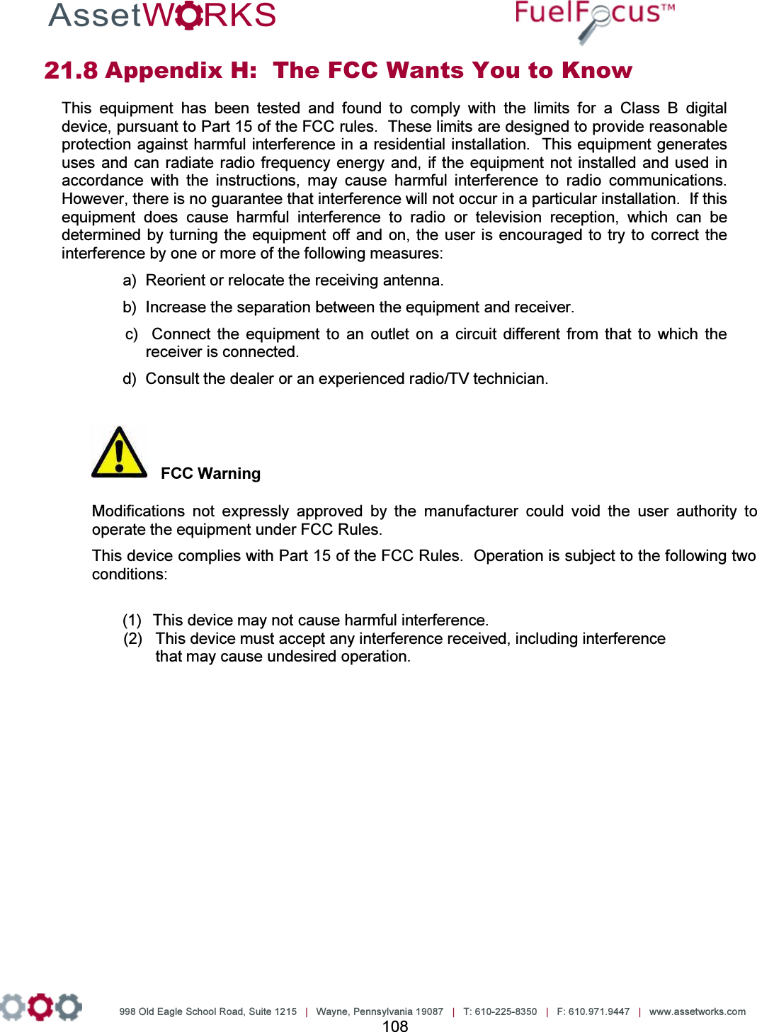
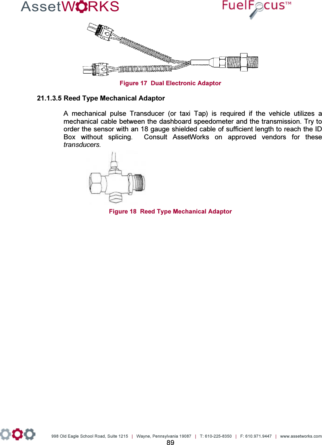
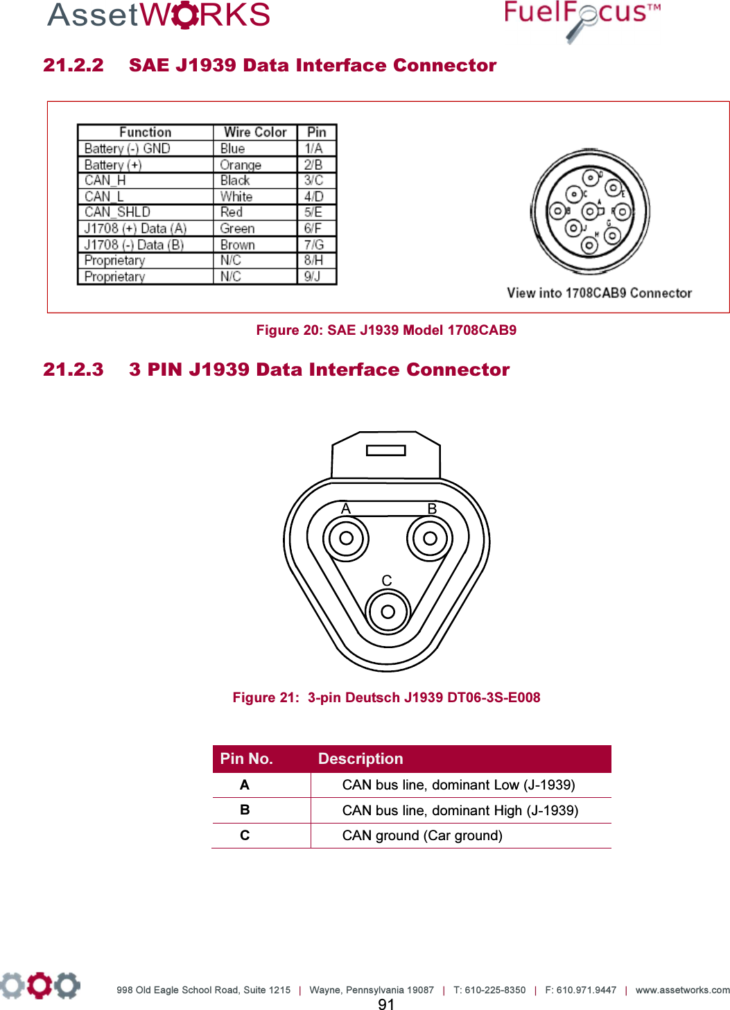
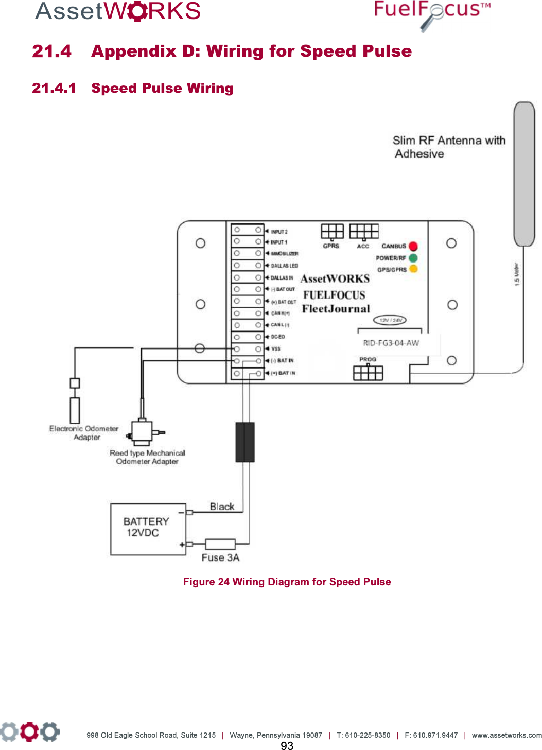
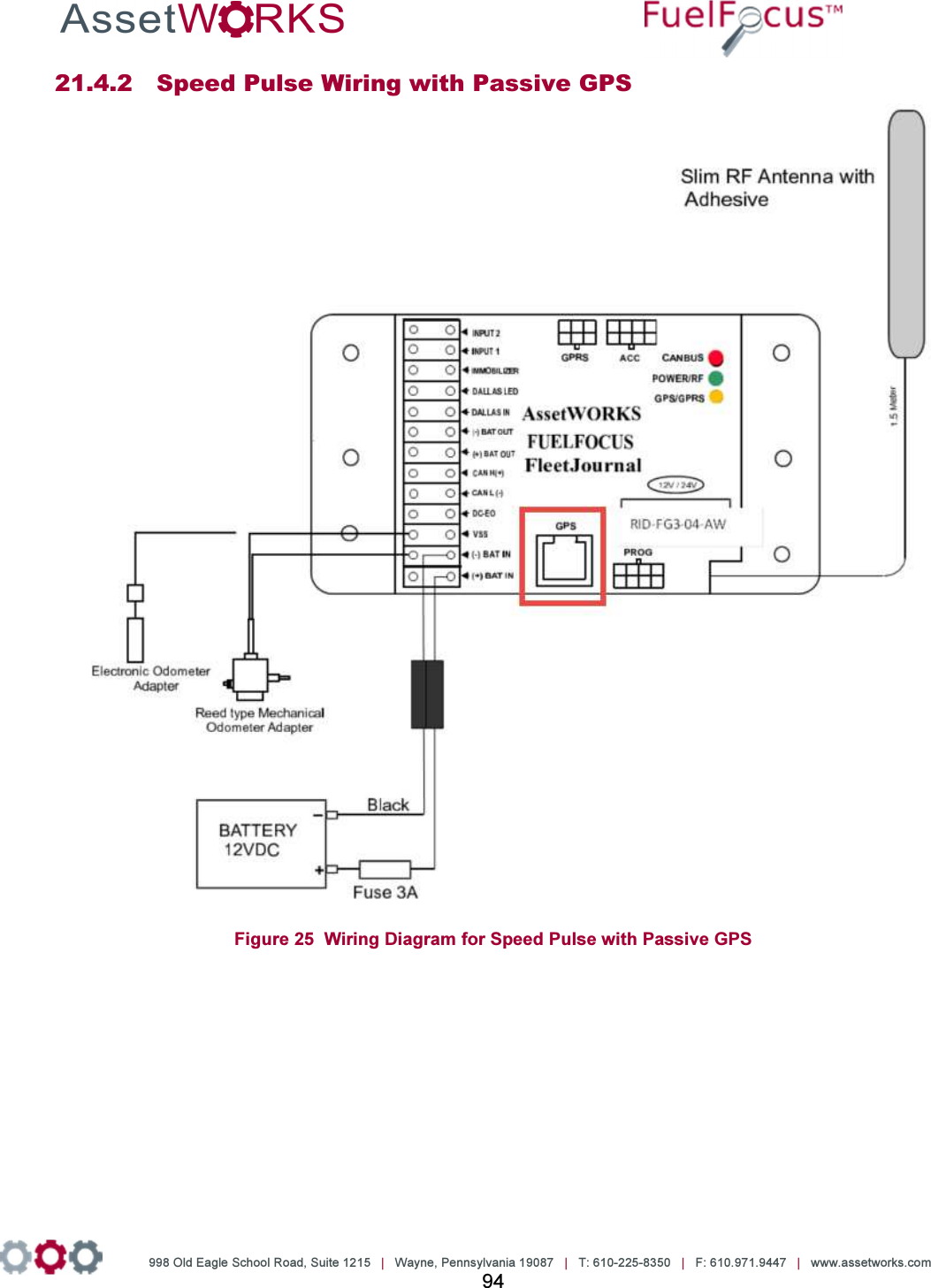
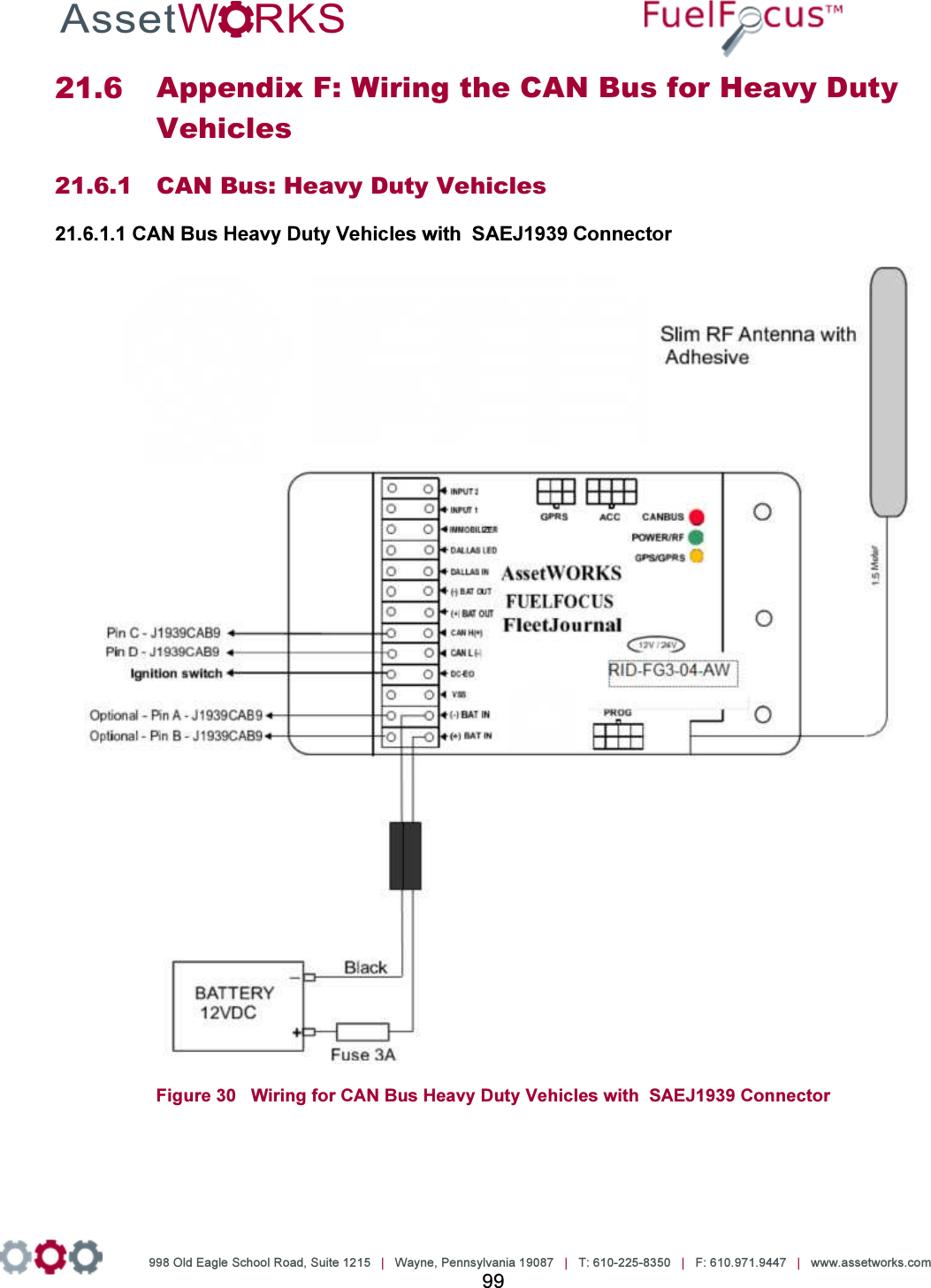
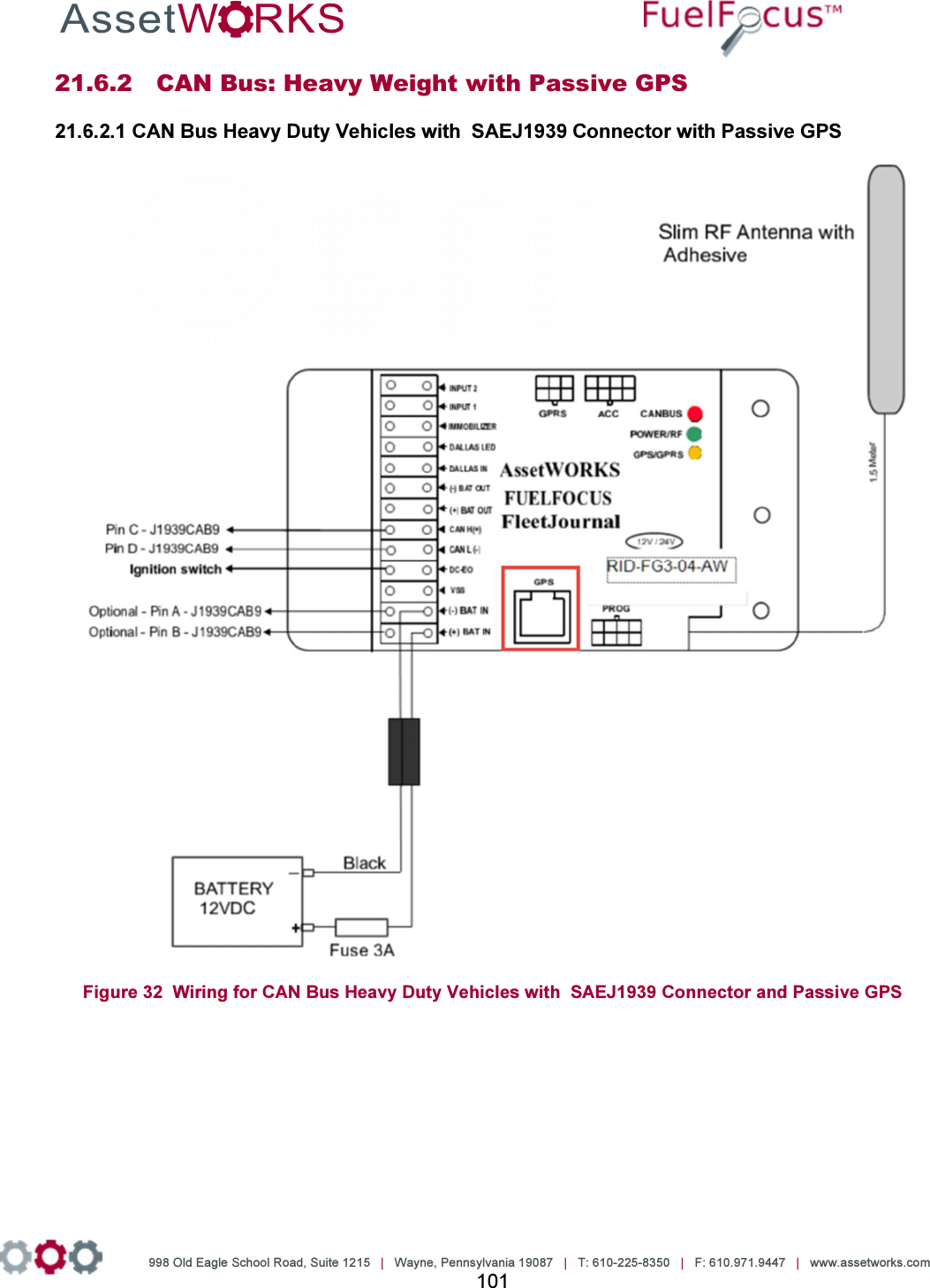
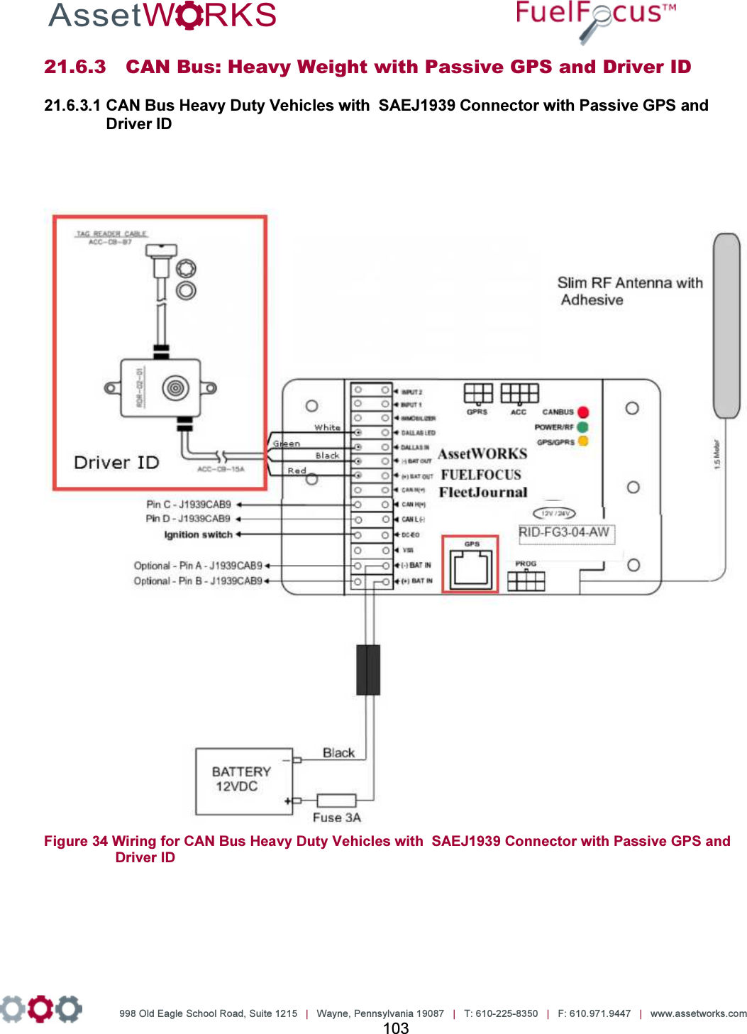
![998 Old Eagle School Road, Suite 1215 | Wayne, Pennsylvania 19087 | T: 610-225-8350 | F: 610.971.9447 | www.assetworks.com 3 9.2.1 Troubleshooting ......................................................................................................... 81 10 Connecting the FJ3 to the GPS Tracking Device [Optional] ................................................... 82 11 Driver ID [Optional] ................................................................................................................ 84 Connecting the Driver ID ................................................................................................... 84 Installing the Driver ID Reader [Tag Reader] ..................................................................... 85 12 Appendices ............................................................................................................................ 87 Appendix A: Capturing Vehicle Data ................................................................................. 87 12.1.1 Capturing Odometer and Engine Hours Information................................................... 87 12.1.2 Vehicle Data Collection (VDC) - Option...................................................................... 87 12.1.3 Vehicle Speed Sensor (VSS) ..................................................................................... 87 Appendix B: CAN Bus Data Connectors .......................................................................... 90 12.2.1 Vehicle OBD-II Connector J1962 ............................................................................... 90 12.2.2 SAE J1939 Data Interface Connector ........................................................................ 91 12.2.3 3 PIN J1939 Data Interface Connector....................................................................... 91 Appendix C: J1708 Data Connectors ................................................................................ 92 12.3.1 SAE J1708 Data Interface Cables .............................................................................. 92 Option 1: SAE J1708 Model 1708CAB9 ................................................................................... 92 Option 2: SAE J1708 Model 1708CAB ..................................................................................... 92 Appendix D: Wiring for Speed Pulse ................................................................................. 93 12.4.1 Speed Pulse Wiring ................................................................................................... 93 12.4.2 Speed Pulse Wiring with Passive GPS ...................................................................... 94 12.4.3 Speed Pulse Wiring with Passive GPS and Driver ID ................................................. 95 Appendix E: CAN Bus Wiring for Light Duty Vehicles ........................................................ 96 12.5.1 CAN Bus: Light Duty Vehicles .................................................................................... 96 12.5.2 CAN Bus: Light Duty with Passive GPS ..................................................................... 97 12.5.3 CAN Bus: Light Duty with Passive GPS and Driver ID ............................................... 98 Appendix F: CAN Bus Wiring for Heavy Duty Vehicles ..................................................... 99 12.6.1 CAN Bus: Heavy Duty Vehicles ................................................................................. 99 12.6.2 CAN Bus: Heavy Weight with Passive GPS ............................................................. 101 12.6.3 CAN Bus: Heavy Weight with Passive GPS and Driver ID ....................................... 103 Appendix G: J1708CAB [6-pin] Connector Wiring ........................................................... 105 12.7.1 Wiring for the J1708CAB [6-pin] Connector ............................................................. 105 12.7.2 Wiring for the J1708CAB [6-pin] Connector with Passive GPS ................................ 106 12.7.3 Wiring for the J1708CAB [6-pin] Connector with Passive GPS and Driver ID ........... 107 Appendix H: The FCC Wants You to Know .................................................................... 108](https://usermanual.wiki/Roseman-Engineering/2288/User-Guide-3265186-Page-3.png)

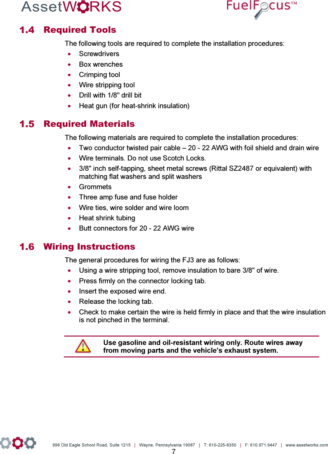

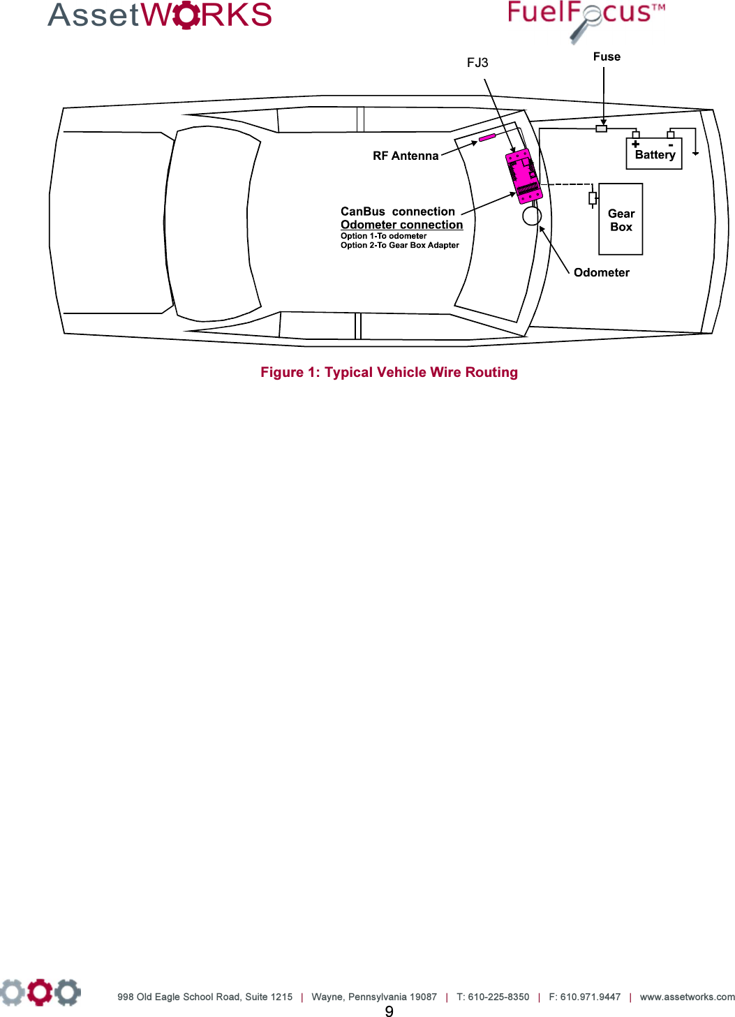

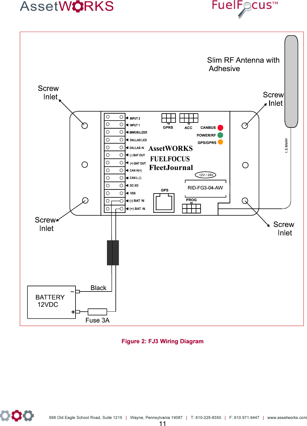

![998 Old Eagle School Road, Suite 1215 | Wayne, Pennsylvania 19087 | T: 610-225-8350 | F: 610.971.9447 | www.assetworks.com 13 4 Wiring VSS or Pulse Vehicles Locating the Vehicle Speed Sensor (VSS) The VSS usually originates near the rear of the transmission case. From there it usually travels to the engine control computer, speedometer and the cruise control computer. Pick a location to tap the circuit near the engine control computer interface, reducing risk of incorrect data due to ignition noise. Also, as with any electronic accessory, a good ground connection is necessary. Improper grounding could result in a ground loop condition, which may affect the accuracy of the unit. Note AssetWorks can provide you with an aftermarket catalog for VSS+ wire, its color, and how many pulses per mile the vehicle has. Connect the Data Interface to the FJ3 The instructions for this procedure depend on the type of vehicle To view how to capture vehicle data, refer to the Fueling Options Either SVID [Fuel Inlet Antenna Connector P/N RID-IN-54] Or Hardwire [Fuel Intel Antenna Connector P/N RID-EM-02] Both options also require a Fuel Intel Antenna [P/N RVC-XX –XX] SVID Mounting and Installation 4.3.1 Mounting the Fuel Inlet Antenna (FIA) Note Use shielded cable type Olympic part # 2886 or equivalent, polypropylene insulated, twisted pair, aluminum Mylar shield, 20 – 22 AWG stranded tinned copper drain wire, chrome vinyl jacket. Temperature rating: -20ºC to 60ºC. Connect the FIA coil before mounting, to avoid using the heat gun near the fuel tank. Before making this connection, plan on where you are going to mount the SVID. Then make sure you have clearance to pass the SVID from the filler neck to the mounting location. If you do not have enough clearance, first position the FIA coil on the vehicle. Then pull the wire out to a safe distance (at least three feet from the fuel filler neck) to heat the shrink-wrap insulation. Then pull the wire back for final mounting. Select a Fuel Inlet Antenna (FIA) with an internal diameter that allows it to fit snugly over the](https://usermanual.wiki/Roseman-Engineering/2288/User-Guide-3265186-Page-13.png)

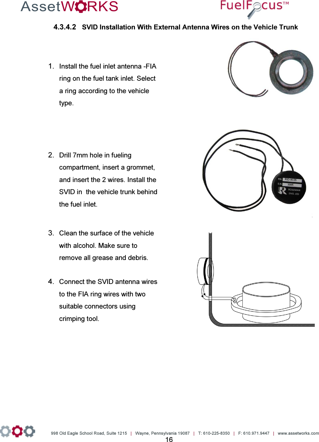


![998 Old Eagle School Road, Suite 1215 | Wayne, Pennsylvania 19087 | T: 610-225-8350 | F: 610.971.9447 | www.assetworks.com 20 To install the Hardwire FIA: 1. Select a fuel inlet antenna diameter to fit the vehicle’s fuel tank inlet [one size larger]. 2. Install it using the dedicated snaps provided. 3. Make sure the fuel inlet antenna cable is long enough to reach the location where the FleetJournal 3 will be installed. Note If necessary the cable may be extended. Use shielded cable type Olympic part # 2886 or equivalent, polypropylene insulated, twisted pair, aluminum Mylar shield, 20 – 22 AWG stranded tinned copper drain wire, chrome vinyl jacket. Temperature rating: -20ºC to 60ºC. 4. Solder and/or use moisture. To prevent connection problems in the future, proof the connections and if necessary shrink the tubing. 5. Install the FleetJournal 3. See Chapter 3 FJ3 Installation. 6. Connect the hardwire FIA connector to the FleetJournal 3 [FJ3] ACC connector. 7. Install the hardwire FIA on the FJ3 wall utilizing the magnetic base. 8. Plug the fuel inlet antenna wires into the green connection points next to each other.](https://usermanual.wiki/Roseman-Engineering/2288/User-Guide-3265186-Page-20.png)
![998 Old Eagle School Road, Suite 1215 | Wayne, Pennsylvania 19087 | T: 610-225-8350 | F: 610.971.9447 | www.assetworks.com 21 4.4.1 Troubleshooting If the Hardwire FIA connection does not work [no proper signal], do the following: 1. Ensure that you are using a correct FIA and have a signal of at least 10 cm. If not replace the FIA. 2. If there is still no proper signal, replace the FIA wire connection. Note The Fuel Inlet Antenna Connector is a sealed unit and cannot be repaired in the field. Please return the defective units. Download an RMA from the AssetWorks PartWorks website.](https://usermanual.wiki/Roseman-Engineering/2288/User-Guide-3265186-Page-21.png)
![998 Old Eagle School Road, Suite 1215 | Wayne, Pennsylvania 19087 | T: 610-225-8350 | F: 610.971.9447 | www.assetworks.com 22 5 Connecting the FJ3 to the GPS Tracking Device [Optional] The GPS device tracks the location of vehicles in the field. Figure 12 GPS Antenna Cable](https://usermanual.wiki/Roseman-Engineering/2288/User-Guide-3265186-Page-22.png)

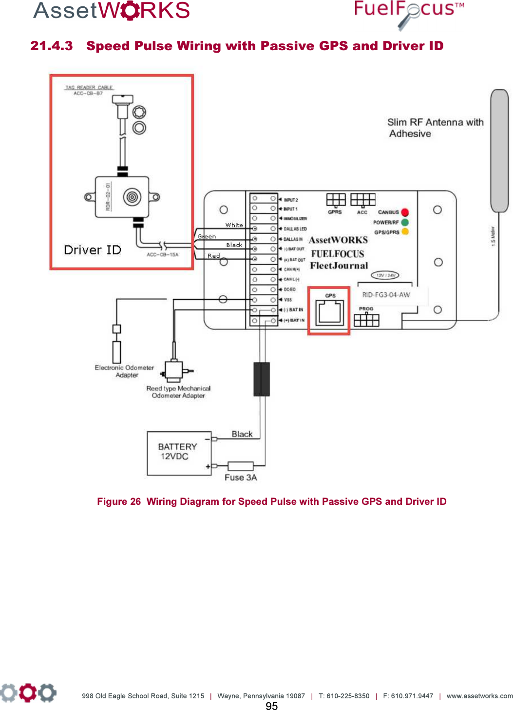
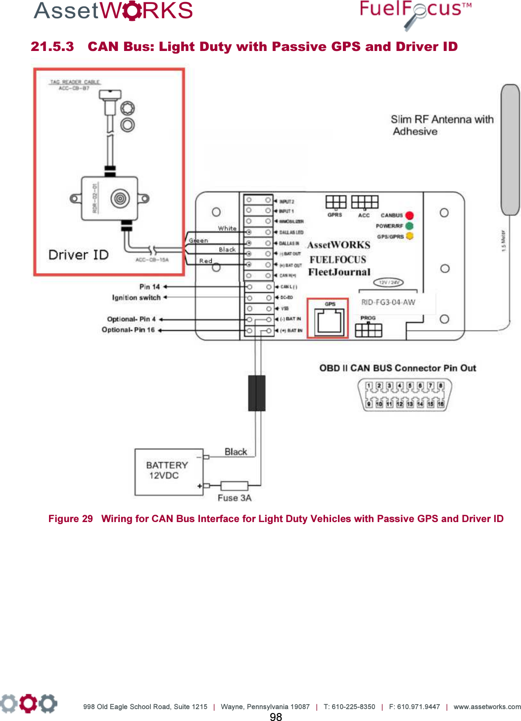
![998 Old Eagle School Road, Suite 1215 | Wayne, Pennsylvania 19087 | T: 610-225-8350 | F: 610.971.9447 | www.assetworks.com 24 6 Driver ID [Optional] Connecting the Driver ID To identify the driver of the vehicle, connect the Tag Reader wires to the FJ3 as follows: Wire Color Connect to: White Dallas LED Green Dallas In Black (-) Bat Out Red (+) Bat In See Figure 13 Figure 13: Connecting the Driver ID reader to the FJ3](https://usermanual.wiki/Roseman-Engineering/2288/User-Guide-3265186-Page-24.png)
![998 Old Eagle School Road, Suite 1215 | Wayne, Pennsylvania 19087 | T: 610-225-8350 | F: 610.971.9447 | www.assetworks.com 25 Installing the Driver ID Reader [Tag Reader] Note: Place the Tag reader on the dashboard so that the Dallas key can be easily read. 1. Wire the Tag Reader cables to the FJ3 – see section Error! Reference source not found. Error! Reference source not found.. 2. Make a ½” hole on the dashboard for the Tag Reader. 3. Pull the Tag Reader through the hole. 4. Connect the Com. Cable ACC-CB-15A cable to the FJ3. Figure 14 COM Cable ACC-CB-15A 5. Connect the Reader Cable ACC-CB-B7 to the Driver ID Reader. Figure 15 Reader Cable ACC-CB-B7](https://usermanual.wiki/Roseman-Engineering/2288/User-Guide-3265186-Page-25.png)

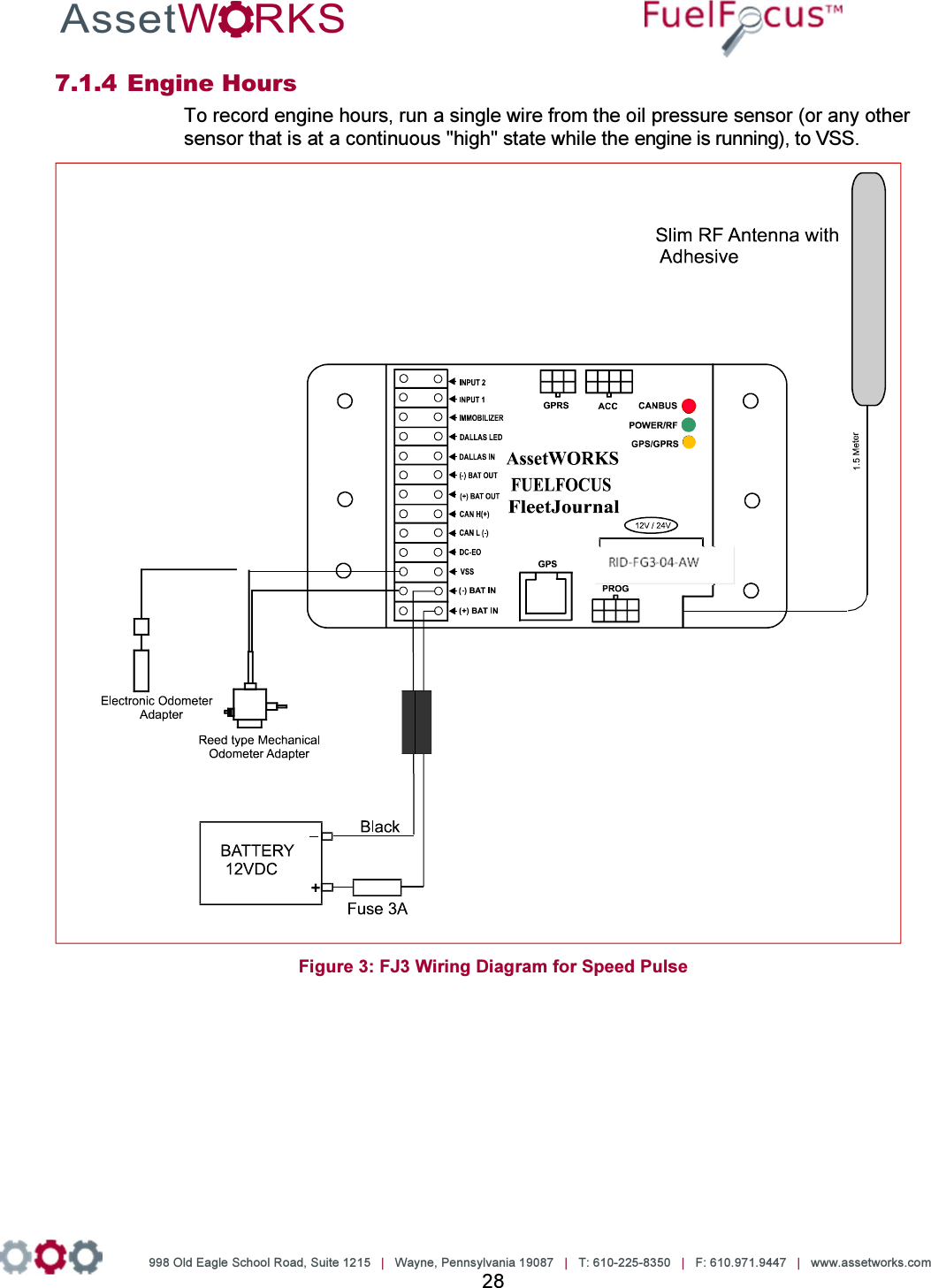
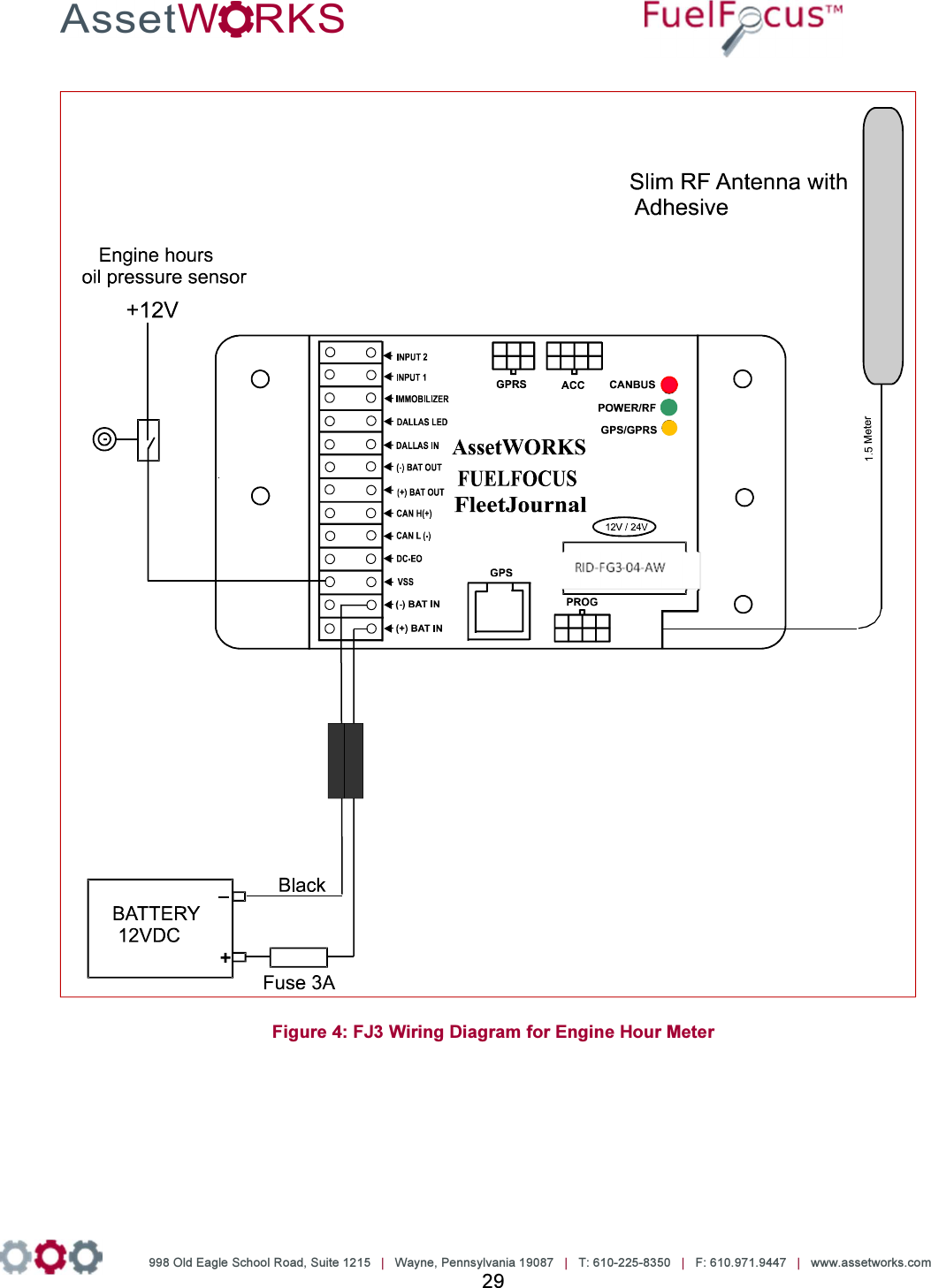
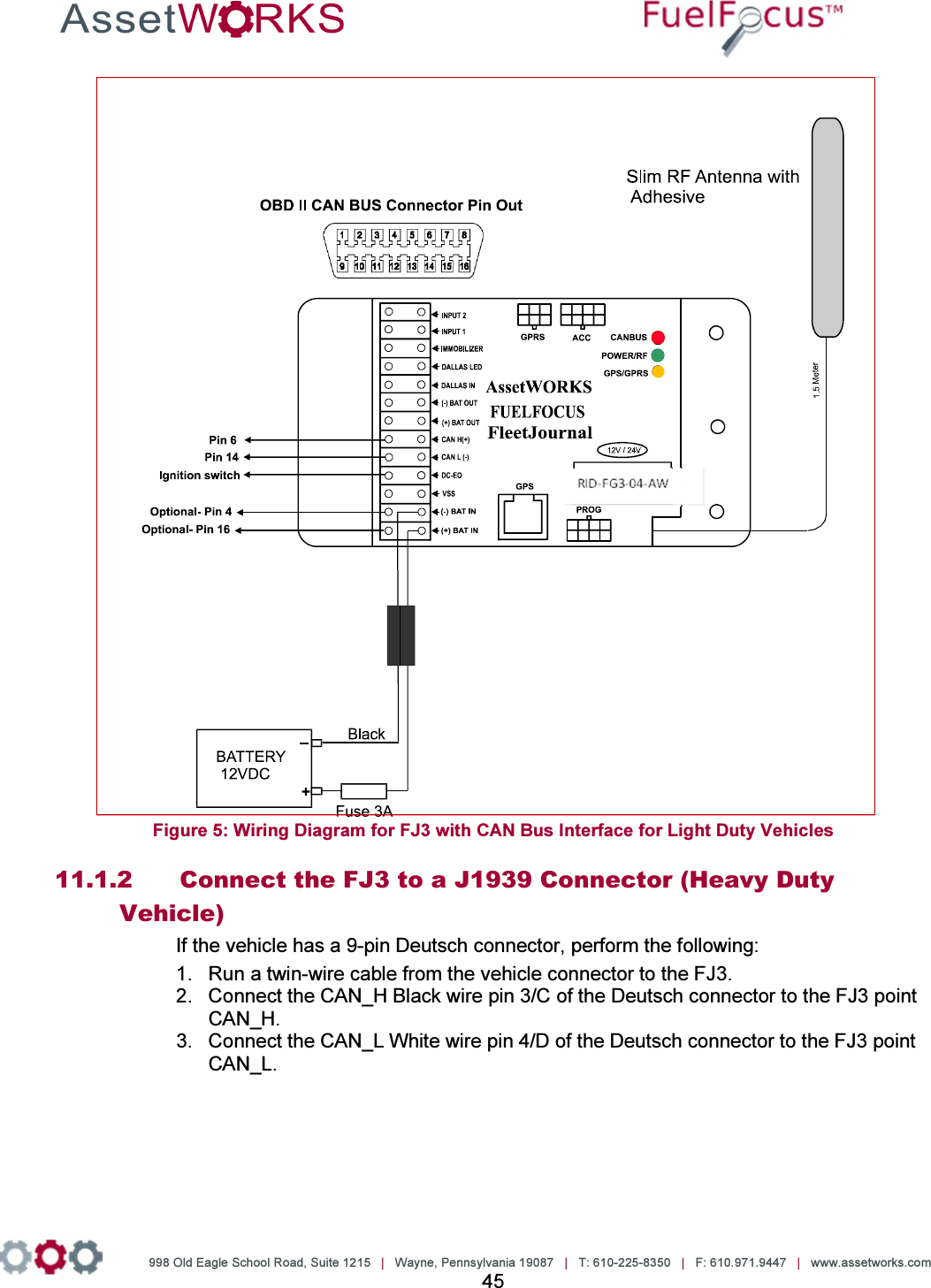
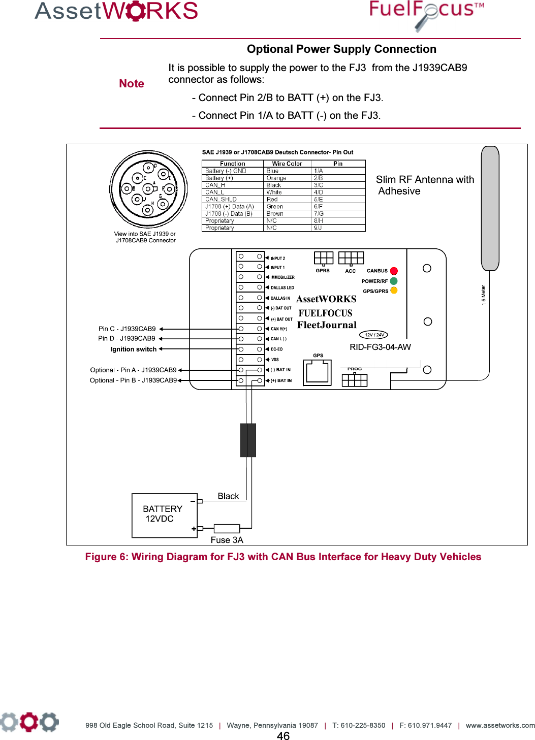
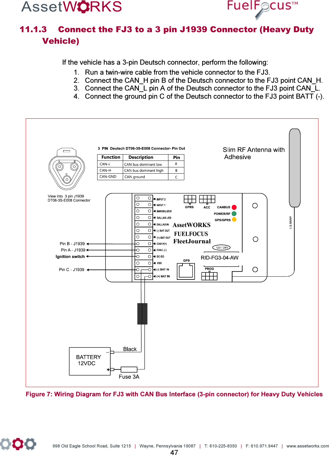
![998 Old Eagle School Road, Suite 1215 | Wayne, Pennsylvania 19087 | T: 610-225-8350 | F: 610.971.9447 | www.assetworks.com 30 8 Wiring the CAN Bus Vehicles Connect the Ignition Switch to the FJ3 1. Run a wire from the vehicle ignition switch (or start/stop button on some hybrid models) to the DC-EO terminal on the FJ3 (refer to Figure 5: Wiring Diagram for FJ3 with CAN Bus Interface for Light Duty Vehicles and Figure 6: Wiring Diagram for FJ3 with CAN Bus Interface for Heavy Duty Vehicles or Figure 7: Wiring Diagram for FJ3 with CAN Bus Interface (3-pin connector) for Heavy Duty Vehicles) 2. The FJ3 needs constant 12 or 24 volt power at the BAT+ and BAT- terminals Note FJ3 will not function properly if an ignition On/Off wire is not connected to the DC-EO terminal. FJ3 goes into Sleep mode (Power Save) 30 minutes after turning off the ignition. Connect the Data Interface to the FJ3 The instructions for this procedure depend on the type of vehicle, whether it is a heavy duty vehicle or a light duty vehicle. Light duty vehicles have an OBD II connector, while heavy duty vehicles have a SAE J1939 connector. The following sections provide instructions for both types of vehicles. To view the connectors’ pin out information, refer to Fueling Options Either SVID [Fuel Inlet Antenna Connector P/N RID-IN-54] Or Hardwire [Fuel Intel Antenna Connector P/N RID-EM-02] Both options also require a Fuel Intel Antenna [P/N RVC-XX –XX] SVID Mounting and Installation 8.3.1 Mounting the Fuel Inlet Antenna (FIA) Note Use shielded cable type Olympic part # 2886 or equivalent, polypropylene insulated, twisted pair, aluminum Mylar shield, 20 – 22 AWG stranded tinned copper drain wire, chrome vinyl jacket. Temperature rating: -20ºC to 60ºC. Connect the FIA coil before mounting, to avoid using the heat gun near the fuel tank. Before making this connection, plan on where you are going to mount the SVID. Then make sure you have clearance to pass the SVID from the filler neck to the mounting location. If you do not have enough clearance, first position the FIA coil on the vehicle. Then pull the wire out to a safe distance (at least three feet from the fuel filler neck) to heat the shrink-wrap insulation. Then pull the wire back for final mounting.](https://usermanual.wiki/Roseman-Engineering/2288/User-Guide-3265186-Page-30.png)


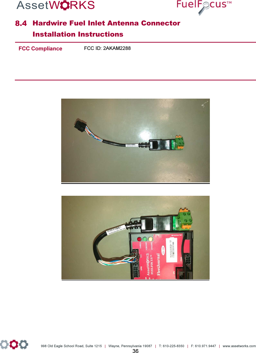
![998 Old Eagle School Road, Suite 1215 | Wayne, Pennsylvania 19087 | T: 610-225-8350 | F: 610.971.9447 | www.assetworks.com 37 To install the Hardwire FIA: 9. Select a fuel inlet antenna diameter to fit the vehicle’s fuel tank inlet [one size larger]. 10. Install it using the dedicated snaps provided. 11. Make sure the fuel inlet antenna cable is long enough to reach the location where the FleetJournal 3 will be installed. Note If necessary the cable may be extended. Use shielded cable type Olympic part # 2886 or equivalent, polypropylene insulated, twisted pair, aluminum Mylar shield, 20 – 22 AWG stranded tinned copper drain wire, chrome vinyl jacket. Temperature rating: -20ºC to 60ºC. 12. Solder and/or use moisture. To prevent connection problems in the future, proof the connections and if necessary shrink the tubing. 13. Install the FleetJournal 3. See Chapter 3 FJ3 Installation. 14. Connect the hardwire FIA connector to the FleetJournal 3 [FJ3] ACC connector. 15. Install the hardwire FIA on the FJ3 wall utilizing the magnetic base. 16. Plug the fuel inlet antenna wires into the green connection points next to each other.](https://usermanual.wiki/Roseman-Engineering/2288/User-Guide-3265186-Page-37.png)
![998 Old Eagle School Road, Suite 1215 | Wayne, Pennsylvania 19087 | T: 610-225-8350 | F: 610.971.9447 | www.assetworks.com 38 8.4.1 Troubleshooting If the Hardwire FIA connection does not work [no proper signal], do the following: 3. Ensure that you are using a correct FIA and have a signal of at least 10 cm. If not replace the FIA. 4. If there is still no proper signal, replace the FIA wire connection. Note The Fuel Inlet Antenna Connector is a sealed unit and cannot be repaired in the field. Please return the defective units. Download an RMA from the AssetWorks PartWorks website.](https://usermanual.wiki/Roseman-Engineering/2288/User-Guide-3265186-Page-38.png)
![998 Old Eagle School Road, Suite 1215 | Wayne, Pennsylvania 19087 | T: 610-225-8350 | F: 610.971.9447 | www.assetworks.com 39 9 Connecting the FJ3 to the GPS Tracking Device [Optional] The GPS device tracks the location of vehicles in the field. Figure 12 GPS Antenna Cable](https://usermanual.wiki/Roseman-Engineering/2288/User-Guide-3265186-Page-39.png)

![998 Old Eagle School Road, Suite 1215 | Wayne, Pennsylvania 19087 | T: 610-225-8350 | F: 610.971.9447 | www.assetworks.com 41 10 Driver ID [Optional] Connecting the Driver ID To identify the driver of the vehicle, connect the Tag Reader wires to the FJ3 as follows: Wire Color Connect to: White Dallas LED Green Dallas In Black (-) Bat Out Red (+) Bat In See Figure 13 Figure 13: Connecting the Driver ID reader to the FJ3](https://usermanual.wiki/Roseman-Engineering/2288/User-Guide-3265186-Page-41.png)
![998 Old Eagle School Road, Suite 1215 | Wayne, Pennsylvania 19087 | T: 610-225-8350 | F: 610.971.9447 | www.assetworks.com 42 Installing the Driver ID Reader [Tag Reader] Note: Place the Tag reader on the dashboard so that the Dallas key can be easily read. 6. Wire the Tag Reader cables to the FJ3 – see section Error! Reference source not found. Error! Reference source not found.. 7. Make a ½” hole on the dashboard for the Tag Reader. 8. Pull the Tag Reader through the hole. 9. Connect the Com. Cable ACC-CB-15A cable to the FJ3. Figure 14 COM Cable ACC-CB-15A 10. Connect the Reader Cable ACC-CB-B7 to the Driver ID Reader. Figure 15 Reader Cable ACC-CB-B7](https://usermanual.wiki/Roseman-Engineering/2288/User-Guide-3265186-Page-42.png)


![998 Old Eagle School Road, Suite 1215 | Wayne, Pennsylvania 19087 | T: 610-225-8350 | F: 610.971.9447 | www.assetworks.com 48 12 Wiring J1708 Vehicles Connect the Ignition Switch to the FJ3 Run a wire from the vehicle ignition switch to the DC-EO terminal on the FJ3 (see Figure 2). Note FJ3 does not function properly if an ignition On/Off wire is not connected. FJ3 goes into Sleep mode 30 min after turning off the ignition. Connect the Data Interface to the FJ3 The instructions for this procedure depend on the type of the connector equipped with the vehicle – whether it is a J1708 CAB9 (9 pin) connector or a J1708 CAB (6 pin) connector. The following sections provide instructions for both types of vehicles. To view the connectors’ pin-out information, refer to the Fueling Options Either SVID [Fuel Inlet Antenna Connector P/N RID-IN-54] Or Hardwire [Fuel Intel Antenna Connector P/N RID-EM-02] Both options also require a Fuel Intel Antenna [P/N RVC-XX –XX] SVID Mounting and Installation 12.3.1 Mounting the Fuel Inlet Antenna (FIA) Note Use shielded cable type Olympic part # 2886 or equivalent, polypropylene insulated, twisted pair, aluminum Mylar shield, 20 – 22 AWG stranded tinned copper drain wire, chrome vinyl jacket. Temperature rating: -20ºC to 60ºC. Connect the FIA coil before mounting, to avoid using the heat gun near the fuel tank. Before making this connection, plan on where you are going to mount the SVID. Then make sure you have clearance to pass the SVID from the filler neck to the mounting location. If you do not have enough clearance, first position the FIA coil on the vehicle. Then pull the wire out to a safe distance (at least three feet from the fuel filler neck) to heat the shrink-wrap insulation. Then pull the wire back for final mounting. Select a Fuel Inlet Antenna (FIA) with an internal diameter that allows it to fit snugly over the](https://usermanual.wiki/Roseman-Engineering/2288/User-Guide-3265186-Page-48.png)


![998 Old Eagle School Road, Suite 1215 | Wayne, Pennsylvania 19087 | T: 610-225-8350 | F: 610.971.9447 | www.assetworks.com 55 To install the Hardwire FIA: 17. Select a fuel inlet antenna diameter to fit the vehicle’s fuel tank inlet [one size larger]. 18. Install it using the dedicated snaps provided. 19. Make sure the fuel inlet antenna cable is long enough to reach the location where the FleetJournal 3 will be installed. Note If necessary the cable may be extended. Use shielded cable type Olympic part # 2886 or equivalent, polypropylene insulated, twisted pair, aluminum Mylar shield, 20 – 22 AWG stranded tinned copper drain wire, chrome vinyl jacket. Temperature rating: -20ºC to 60ºC. 20. Solder and/or use moisture. To prevent connection problems in the future, proof the connections and if necessary shrink the tubing. 21. Install the FleetJournal 3. See Chapter 3 FJ3 Installation. 22. Connect the hardwire FIA connector to the FleetJournal 3 [FJ3] ACC connector. 23. Install the hardwire FIA on the FJ3 wall utilizing the magnetic base. 24. Plug the fuel inlet antenna wires into the green connection points next to each other.](https://usermanual.wiki/Roseman-Engineering/2288/User-Guide-3265186-Page-55.png)
![998 Old Eagle School Road, Suite 1215 | Wayne, Pennsylvania 19087 | T: 610-225-8350 | F: 610.971.9447 | www.assetworks.com 56 12.4.1 Troubleshooting If the Hardwire FIA connection does not work [no proper signal], do the following: 5. Ensure that you are using a correct FIA and have a signal of at least 10 cm. If not replace the FIA. 6. If there is still no proper signal, replace the FIA wire connection. Note The Fuel Inlet Antenna Connector is a sealed unit and cannot be repaired in the field. Please return the defective units. Download an RMA from the AssetWorks PartWorks website.](https://usermanual.wiki/Roseman-Engineering/2288/User-Guide-3265186-Page-56.png)
![998 Old Eagle School Road, Suite 1215 | Wayne, Pennsylvania 19087 | T: 610-225-8350 | F: 610.971.9447 | www.assetworks.com 57 13 Connecting the FJ3 to the GPS Tracking Device [Optional] The GPS device tracks the location of vehicles in the field. Figure 12 GPS Antenna Cable](https://usermanual.wiki/Roseman-Engineering/2288/User-Guide-3265186-Page-57.png)

![998 Old Eagle School Road, Suite 1215 | Wayne, Pennsylvania 19087 | T: 610-225-8350 | F: 610.971.9447 | www.assetworks.com 59 14 Driver ID [Optional] Connecting the Driver ID To identify the driver of the vehicle, connect the Tag Reader wires to the FJ3 as follows: Wire Color Connect to: White Dallas LED Green Dallas In Black (-) Bat Out Red (+) Bat In See Figure 13 Figure 13: Connecting the Driver ID reader to the FJ3](https://usermanual.wiki/Roseman-Engineering/2288/User-Guide-3265186-Page-59.png)
![998 Old Eagle School Road, Suite 1215 | Wayne, Pennsylvania 19087 | T: 610-225-8350 | F: 610.971.9447 | www.assetworks.com 60 Installing the Driver ID Reader [Tag Reader] Note: Place the Tag reader on the dashboard so that the Dallas key can be easily read. 11. Wire the Tag Reader cables to the FJ3 – see section Error! Reference source not found. Error! Reference source not found.. 12. Make a ½” hole on the dashboard for the Tag Reader. 13. Pull the Tag Reader through the hole. 14. Connect the Com. Cable ACC-CB-15A cable to the FJ3. Figure 14 COM Cable ACC-CB-15A 15. Connect the Reader Cable ACC-CB-B7 to the Driver ID Reader. Figure 15 Reader Cable ACC-CB-B7](https://usermanual.wiki/Roseman-Engineering/2288/User-Guide-3265186-Page-60.png)


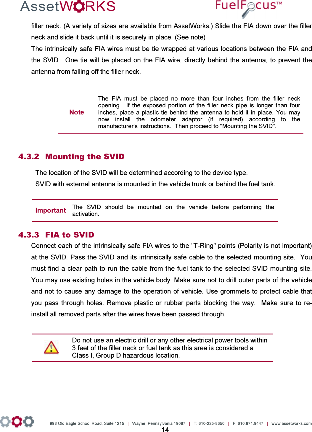
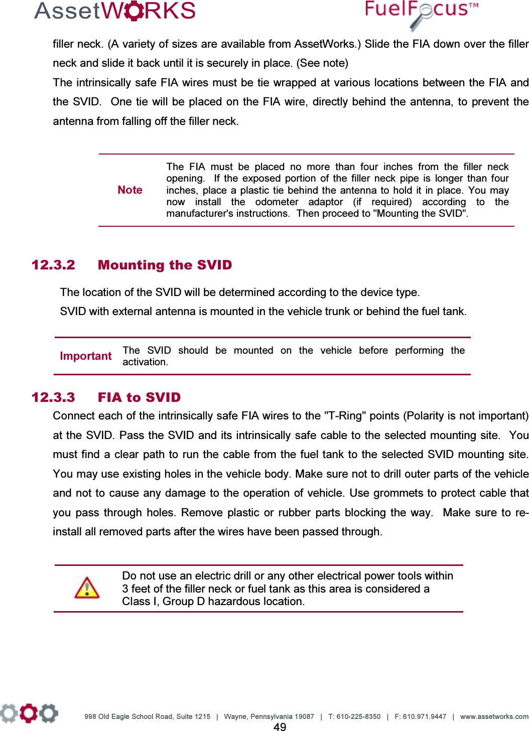
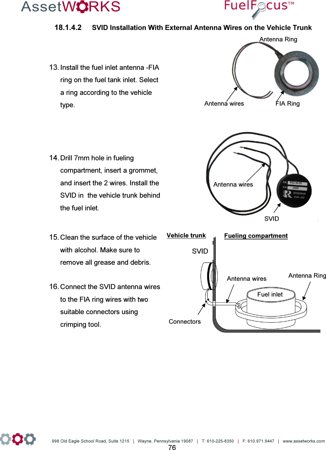
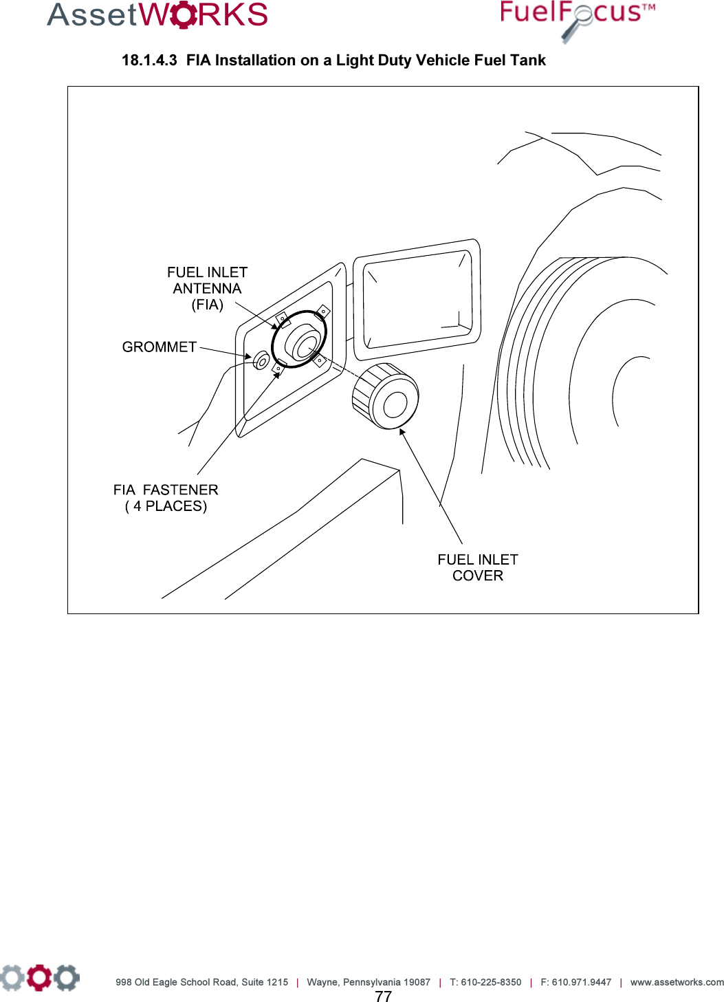
![998 Old Eagle School Road, Suite 1215 | Wayne, Pennsylvania 19087 | T: 610-225-8350 | F: 610.971.9447 | www.assetworks.com 73 18 Fueling Options • Either SVID [Fuel Inlet Antenna Connector P/N RID-IN-54] • Or Hardwire [Fuel Intel Antenna Connector P/N RID-EM-02] Both options also require a Fuel Intel Antenna [P/N RVC-XX –XX] SVID Mounting and Installation 18.1.1 Mounting the Fuel Inlet Antenna (FIA) Note Use shielded cable type Olympic part # 2886 or equivalent, polypropylene insulated, twisted pair, aluminum Mylar shield, 20 – 22 AWG stranded tinned copper drain wire, chrome vinyl jacket. Temperature rating: -20ºC to 60ºC. Connect the FIA coil before mounting, to avoid using the heat gun near the fuel tank. Before making this connection, plan on where you are going to mount the SVID. Then make sure you have clearance to pass the SVID from the filler neck to the mounting location. If you do not have enough clearance, first position the FIA coil on the vehicle. Then pull the wire out to a safe distance (at least three feet from the fuel filler neck) to heat the shrink-wrap insulation. Then pull the wire back for final mounting. Select a Fuel Inlet Antenna (FIA) with an internal diameter that allows it to fit snugly over the filler neck. (A variety of sizes are available from AssetWorks.) Slide the FIA down over the filler neck and slide it back until it is securely in place. (See note) The intrinsically safe FIA wires must be tie wrapped at various locations between the FIA and the SVID. One tie will be placed on the FIA wire, directly behind the antenna, to prevent the antenna from falling off the filler neck. Note The FIA must be placed no more than four inches from the filler neck opening. If the exposed portion of the filler neck pipe is longer than four inches, place a plastic tie behind the antenna to hold it in place. You may now install the odometer adaptor (if required) according to the manufacturer's instructions. Then proceed to "Mounting the SVID".](https://usermanual.wiki/Roseman-Engineering/2288/User-Guide-3265186-Page-73.png)


![998 Old Eagle School Road, Suite 1215 | Wayne, Pennsylvania 19087 | T: 610-225-8350 | F: 610.971.9447 | www.assetworks.com 80 To install the Hardwire FIA: 25. Select a fuel inlet antenna diameter to fit the vehicle’s fuel tank inlet [one size larger]. 26. Install it using the dedicated snaps provided. 27. Make sure the fuel inlet antenna cable is long enough to reach the location where the FleetJournal 3 will be installed. Note If necessary the cable may be extended. Use shielded cable type Olympic part # 2886 or equivalent, polypropylene insulated, twisted pair, aluminum Mylar shield, 20 – 22 AWG stranded tinned copper drain wire, chrome vinyl jacket. Temperature rating: -20ºC to 60ºC. 28. Solder and/or use moisture. To prevent connection problems in the future, proof the connections and if necessary shrink the tubing. 29. Install the FleetJournal 3. See Chapter 3 FJ3 Installation. 30. Connect the hardwire FIA connector to the FleetJournal 3 [FJ3] ACC connector. 31. Install the hardwire FIA on the FJ3 wall utilizing the magnetic base. 32. Plug the fuel inlet antenna wires into the green connection points next to each other. Hardwire FIA connector plus and ACC connector FIA wire connection points](https://usermanual.wiki/Roseman-Engineering/2288/User-Guide-3265186-Page-80.png)
![998 Old Eagle School Road, Suite 1215 | Wayne, Pennsylvania 19087 | T: 610-225-8350 | F: 610.971.9447 | www.assetworks.com 81 18.2.1 Troubleshooting If the Hardwire FIA connection does not work [no proper signal], do the following: 7. Ensure that you are using a correct FIA and have a signal of at least 10 cm. If not replace the FIA. 8. If there is still no proper signal, replace the FIA wire connection. Note The Fuel Inlet Antenna Connector is a sealed unit and cannot be repaired in the field. Please return the defective units. Download an RMA from the AssetWorks PartWorks website. Magnets FIA Wire Connections](https://usermanual.wiki/Roseman-Engineering/2288/User-Guide-3265186-Page-81.png)
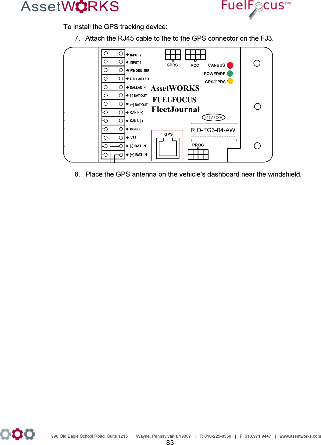
![998 Old Eagle School Road, Suite 1215 | Wayne, Pennsylvania 19087 | T: 610-225-8350 | F: 610.971.9447 | www.assetworks.com 82 19 Connecting the FJ3 to the GPS Tracking Device [Optional] The GPS device tracks the location of vehicles in the field. Figure 12 GPS Antenna Cable](https://usermanual.wiki/Roseman-Engineering/2288/User-Guide-3265186-Page-82.png)
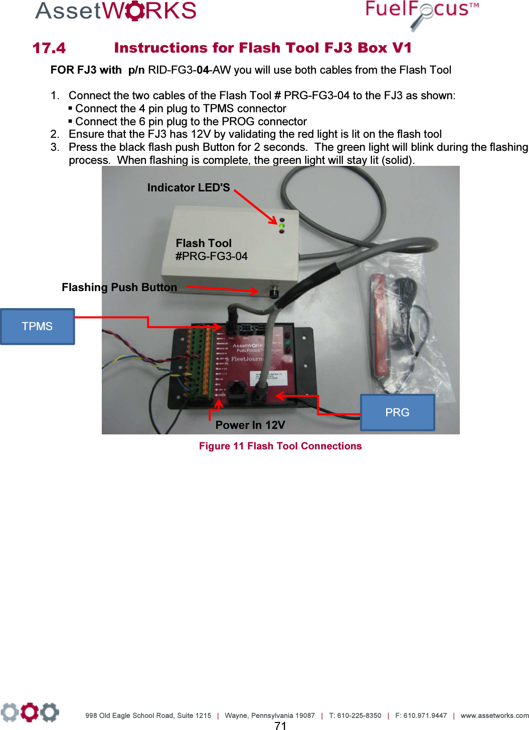
![998 Old Eagle School Road, Suite 1215 | Wayne, Pennsylvania 19087 | T: 610-225-8350 | F: 610.971.9447 | www.assetworks.com 84 20 Driver ID [Optional] Connecting the Driver ID To identify the driver of the vehicle, connect the Tag Reader wires to the FJ3 as follows: Wire Color Connect to: White Dallas LED Green Dallas In Black (-) Bat Out Red (+) Bat In See Figure 13 Figure 13: Connecting the Driver ID reader to the FJ3 RID-FG3-04-AW](https://usermanual.wiki/Roseman-Engineering/2288/User-Guide-3265186-Page-84.png)
![998 Old Eagle School Road, Suite 1215 | Wayne, Pennsylvania 19087 | T: 610-225-8350 | F: 610.971.9447 | www.assetworks.com 85 Installing the Driver ID Reader [Tag Reader] Note: Place the Tag reader on the dashboard so that the Dallas key can be easily read. 16. Wire the Tag Reader cables to the FJ3 – see section Error! Reference source not found. Error! Reference source not found.. 17. Make a ½” hole on the dashboard for the Tag Reader. 18. Pull the Tag Reader through the hole. 19. Connect the Com. Cable ACC-CB-15A cable to the FJ3. Figure 14 COM Cable ACC-CB-15A 20. Connect the Reader Cable ACC-CB-B7 to the Driver ID Reader. Figure 15 Reader Cable ACC-CB-B7](https://usermanual.wiki/Roseman-Engineering/2288/User-Guide-3265186-Page-85.png)


![998 Old Eagle School Road, Suite 1215 | Wayne, Pennsylvania 19087 | T: 610-225-8350 | F: 610.971.9447 | www.assetworks.com 100 21.6.1.2 CAN Bus Heavy Duty Vehicles with [Triangular] 3-pin Deutsch Connector Figure 31 Wiring for the CAN Bus Heavy Duty Vehicles with [Triangular] 3-pin Deutsch Connector](https://usermanual.wiki/Roseman-Engineering/2288/User-Guide-3265186-Page-100.png)
![998 Old Eagle School Road, Suite 1215 | Wayne, Pennsylvania 19087 | T: 610-225-8350 | F: 610.971.9447 | www.assetworks.com 102 21.6.2.2 CAN Bus Heavy Duty Vehicles with [Triangular] 3-pin Deutsch Connector with Passive GPS Figure 33 Wiring for the CAN Bus Heavy Duty Vehicles with [Triangular] 3-pin Deutsch Connector with Passive GPS](https://usermanual.wiki/Roseman-Engineering/2288/User-Guide-3265186-Page-102.png)
![998 Old Eagle School Road, Suite 1215 | Wayne, Pennsylvania 19087 | T: 610-225-8350 | F: 610.971.9447 | www.assetworks.com 104 21.6.3.2 CAN Bus Heavy Duty Vehicles with [Triangular] 3-pin Deutsch Connector with Passive GPS and Driver ID Figure 35 Wiring for the CAN Bus Heavy Duty Vehicles with [Triangular] 3-pin Deutsch Connector with Passive GPS and Driver ID](https://usermanual.wiki/Roseman-Engineering/2288/User-Guide-3265186-Page-104.png)
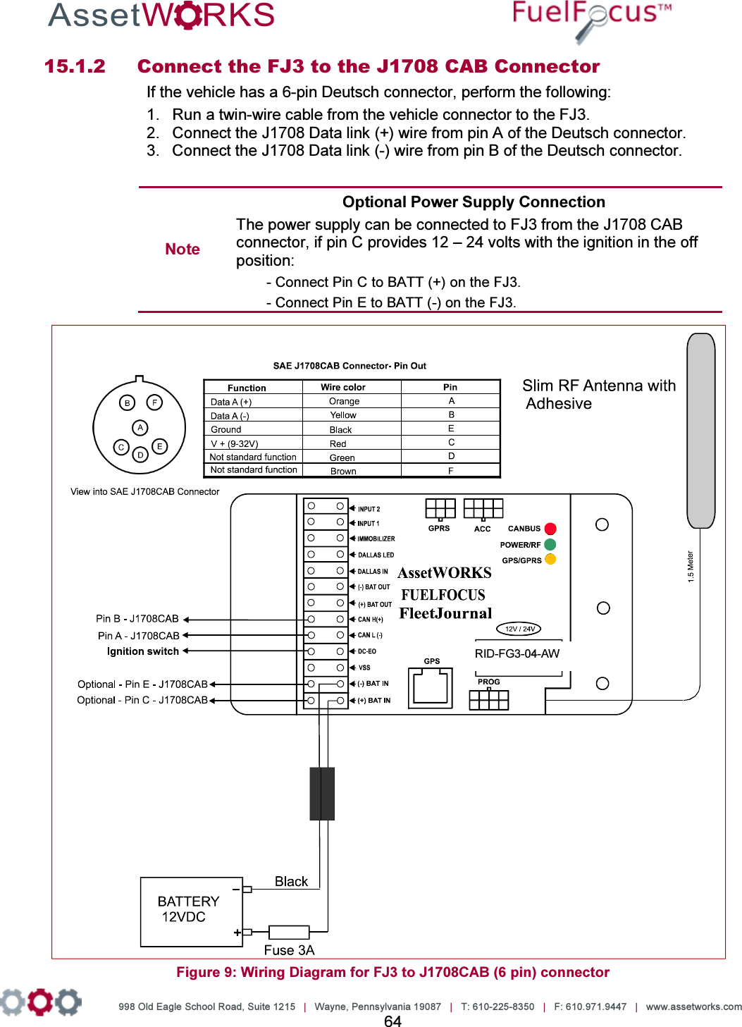
![998 Old Eagle School Road, Suite 1215 | Wayne, Pennsylvania 19087 | T: 610-225-8350 | F: 610.971.9447 | www.assetworks.com 105 Appendix G: Wiring the J1708CAB [6-pin] Connector 21.7.1 Wiring for the J1708CAB [6-pin] Connector Figure 36 Wiring for the J1708CAB [6-pin] Connector](https://usermanual.wiki/Roseman-Engineering/2288/User-Guide-3265186-Page-105.png)
![998 Old Eagle School Road, Suite 1215 | Wayne, Pennsylvania 19087 | T: 610-225-8350 | F: 610.971.9447 | www.assetworks.com 106 21.7.2 Wiring for the J1708CAB [6-pin] Connector with Passive GPS Figure 37 Wiring for the J1708CAB [6-pin] Connector with Passive GPS](https://usermanual.wiki/Roseman-Engineering/2288/User-Guide-3265186-Page-106.png)
![998 Old Eagle School Road, Suite 1215 | Wayne, Pennsylvania 19087 | T: 610-225-8350 | F: 610.971.9447 | www.assetworks.com 107 21.7.3 Wiring for the J1708CAB [6-pin] Connector with Passive GPS and Driver ID Figure 38 Wiring for the J1708CAB [6-pin] Connector with Passive GPS and Driver ID](https://usermanual.wiki/Roseman-Engineering/2288/User-Guide-3265186-Page-107.png)