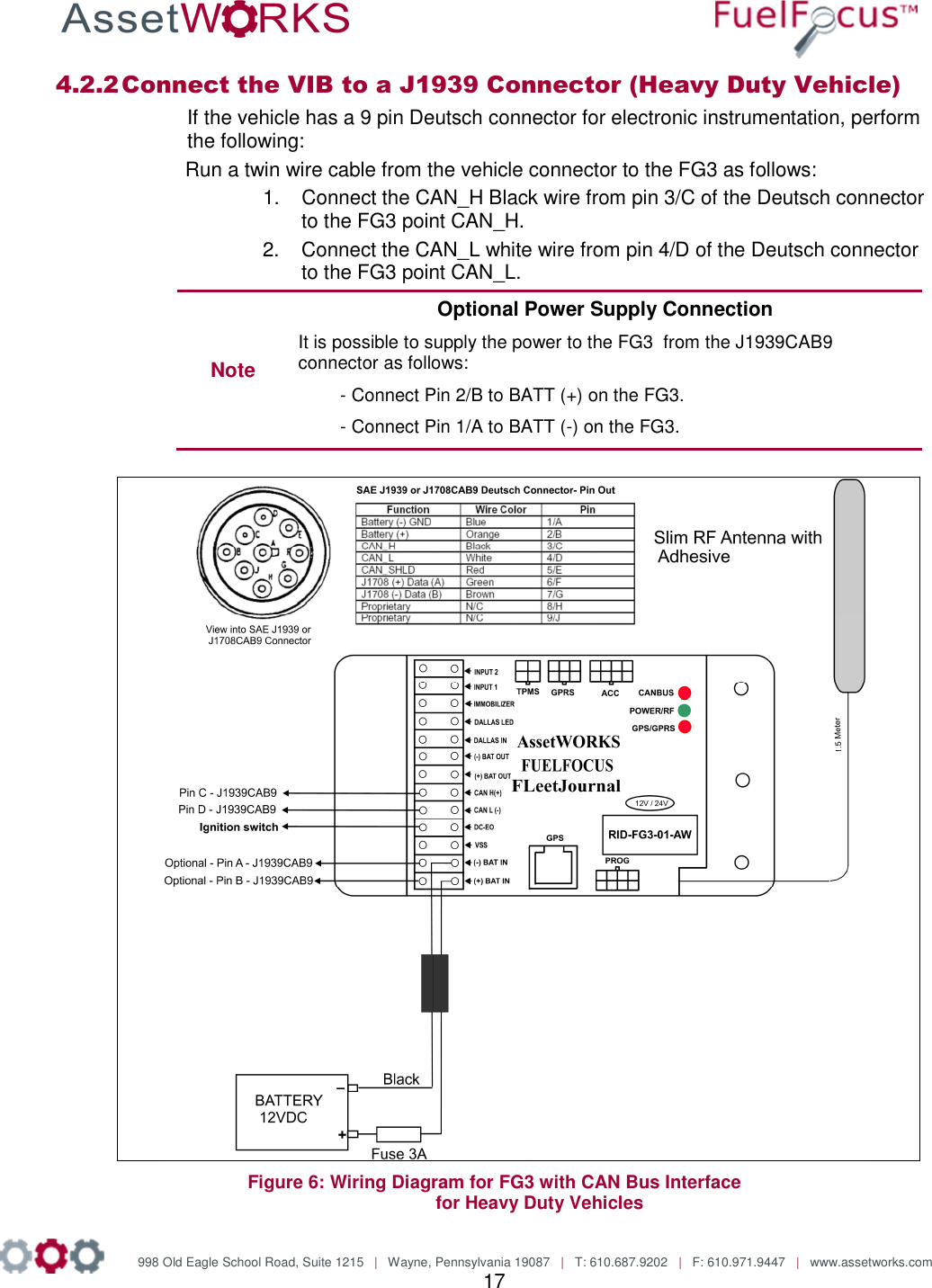
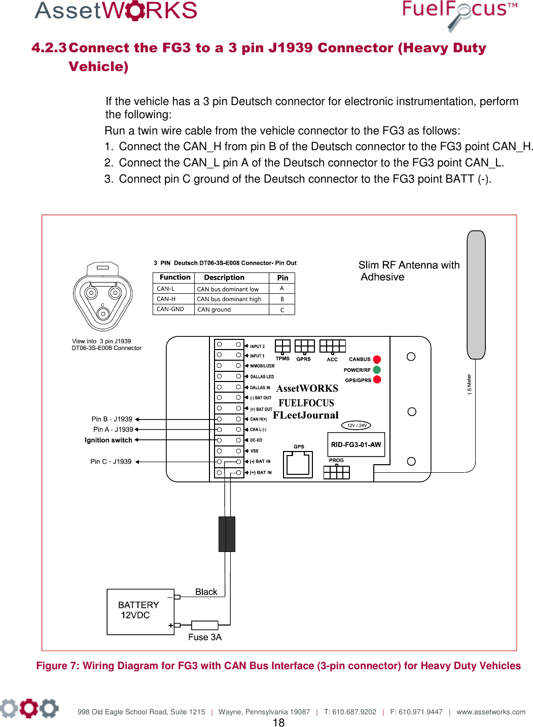
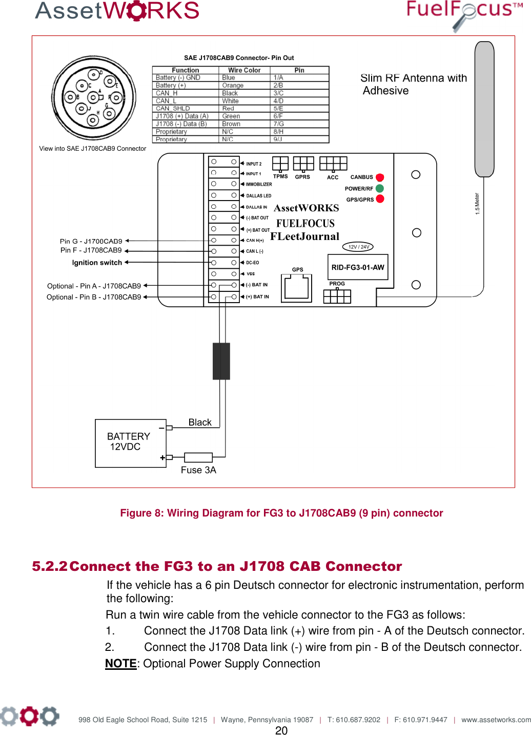
Roseman Engineering FG3 CAR DATA LOGGER-MODULAR FLEET GATE User Manual FG3 Installation 20 10 13

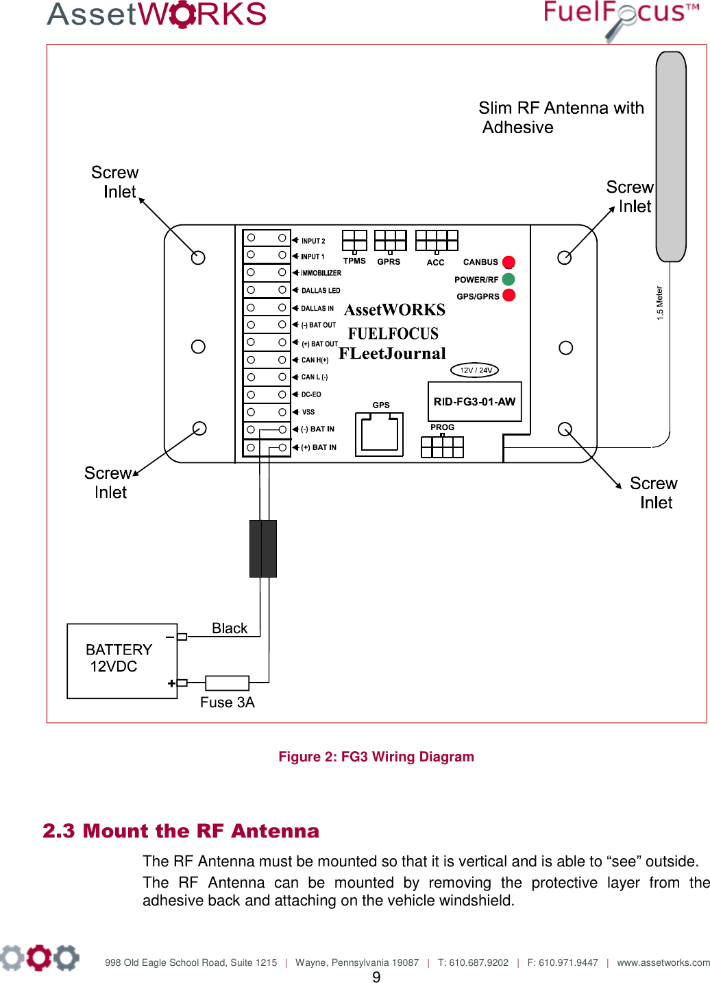
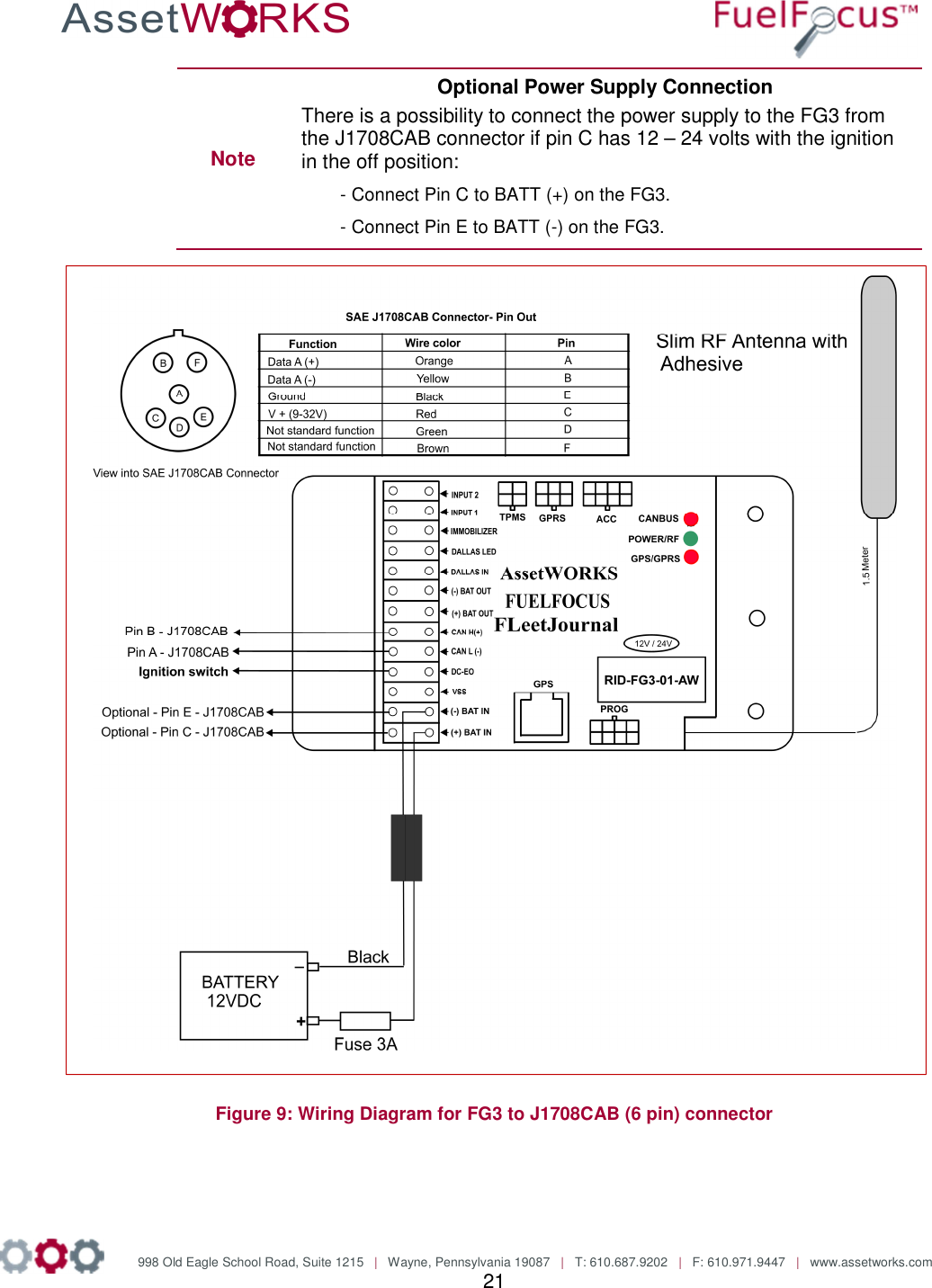
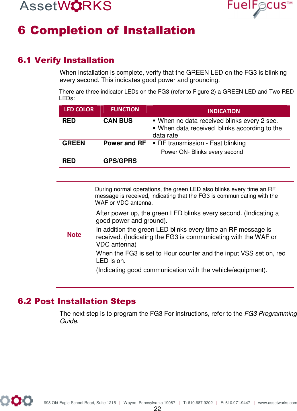
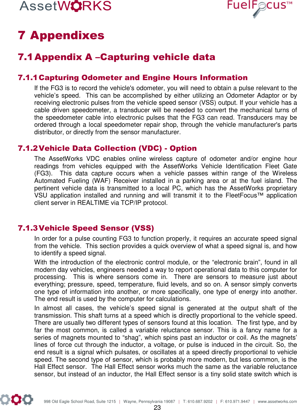
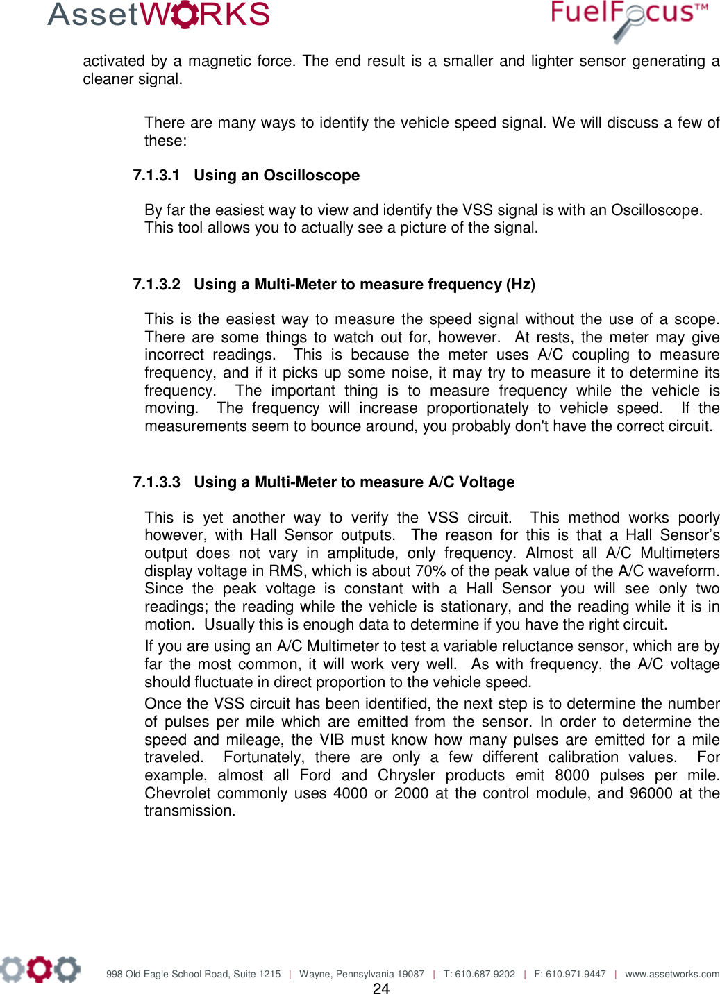
Roseman Engineering Ltd. CAR DATA LOGGER-MODULAR FLEET GATE FG3 Installation 20 10 13

User Manual

     FuelFocus® FMS System Diary Vehicle Subsystem  Modular Fleet Journal Type 3 (FG3) #RID-FG3-01-AW Installation Manual Version 1.0   October   2013 AssetWorks, Inc. 998 Old Eagle School Road, Suite 1215 Wayne, PA 19087  Telephone: 610.225.8350 Facsimile: 610.971.9447  www.assetworks.com Copyright © 2012, AssetWorks, Inc.  All Rights Reserved.
              998 Old Eagle School Road, Suite 1215   |   Wayne, Pennsylvania 19087   |   T: 610.687.9202   |   F: 610.971.9447   |   www.assetworks.com 2  Table of Contents Table of Contents ..................................................................................................................... 2 1 Introduction .............................................................................................................................. 4 1.1 Purpose ............................................................................................................................ 4 1.2 System Overview .............................................................................................................. 4 1.3 Components Overview ...................................................................................................... 4 1.4 Required Tools ................................................................................................................. 6 1.5 Required Materials ............................................................................................................ 6 1.6 Wiring Instructions ............................................................................................................ 6 2 Installation ................................................................................................................................ 7 2.1 FG3 Mounting Location Considerations ............................................................................ 7 2.2 Mount the FG3 .................................................................................................................. 8 2.3 Mount the RF Antenna ...................................................................................................... 9 2.4 Connect the FG3 to the Battery or Power Source ........................................................... 10 2.5 Connect the FG3 to Ground ............................................................................................ 10 3 Wiring the Dual Input Pulse Vehicles ..................................................................................... 11 3.1 Locating the Vehicle Speed Sensor (VSS) ...................................................................... 11 3.2 Connect the Data Interface to the FG3 ............................................................................ 11 4 Wiring the CAN Bus Vehicles ................................................................................................. 15 4.1 Connect the Ignition Switch to the FG3 ........................................................................... 15 4.2 Connect the Data Interface to the FG3 ............................................................................ 15 5 Wiring the J1708 Vehicles ...................................................................................................... 19 5.1 Connect the Ignition Switch to the FG3 ........................................................................... 19 5.2 Connect the Data Interface to the FG3 ............................................................................ 19 6 Completion of Installation ....................................................................................................... 22 6.1 Verify Installation ............................................................................................................ 22 6.2 Post Installation Steps .................................................................................................... 22 7 Appendixes ............................................................................................................................ 23 7.1 Appendix A –Capturing vehicle data ............................................................................... 23 7.2 Appendix B – CAN Bus Data Connectors ....................................................................... 26 7.3 Appendix C – J1708 Data Connectors ............................................................................ 29 7.3.1 SAE J1708 Data Interface Cables ............................................................................ 29 Option 1: SAE J1708 Model 1708CAB9 ................................................................................. 29 Option 2: SAE J1708 Model 1708CAB ................................................................................... 29 7.4 The FCC Wants You to Know ......................................................................................... 30
              998 Old Eagle School Road, Suite 1215   |   Wayne, Pennsylvania 19087   |   T: 610.687.9202   |   F: 610.971.9447   |   www.assetworks.com 3  AssetWorks  Inc.  cannot  guarantee  the  RF  Vehicle  ID  Box  installation  techniques discussed herein are complete and effective on every make, model and year of vehicle and  equipment  now  in  the  marketplace  or  coming  in  the  future.    At  times  vehicle manufacturers make changes to the engine computer, wiring and/or electronics with new model years and in fact also during mid-year production.  After market accessories may also  impact  the installation of  the RF Vehicle  ID  Box. AssetWorks provides  updates  as soon  possible  after  discovering  installation  challenges,  new  OBD  types  or  anything effecting  proper  operation.      We  request  feedback  from  the  many  very  knowledgeable Automotive Technicians working with this technology.   If installation issues arise with new model  years  or  unique  equipment  we  request  immediate  and  detailed  feedback  so corrections and enhancement may be made in a timely fashion.  Working together we can assure that the FuelFocus system remains the finest available. Information on updates and new  programs  or  procedures  will  be  made  available  via  the  Fuel  Focus  installation trainers,  the  newsletter  and  the  customer  support  desk.    AssetWorks  urges  all  trained Technicians  ,  Supervisors  and  Managers  to  avail  themselves  of  the  newsletter  by contacting  " AssetWorks Fuel Support" <fuelsupport@assetworks.com> to be included on the subscription list.    FCC Warning To comply with FCC requirements, a distance of at least 20cm between the equipment and all persons should be maintained during the operation of the equipment.
              998 Old Eagle School Road, Suite 1215   |   Wayne, Pennsylvania 19087   |   T: 610.687.9202   |   F: 610.971.9447   |   www.assetworks.com 4  1 Introduction 1.1 Purpose This FuelFocus® Vehicle Subsystem Installation Manual is provided to assist you in installing the Modular Fleet Journal Type 3 (FG3). Review this manual prior to the installation of the FG3 to ensure proper installation practices. Incorrect installations are the major cause of system malfunctions.  The FG3 must be installed as described in this manual to ensure the reliability and proper operation of the system.  Please read this entire manual before starting your first installation. 1.2 System Overview The AssetWorks FG3 is the integral component of the vehicle subsystem of the AssetWorks FuelFocus® FMS System. To properly install and utilize the FuelFocus® FG3  the following is required: • AssetWorks FuelFocus® Fuel Management System Island Controllers • Pumps/dispensers modified using FuelFocus nozzle tags • WAF Receiver Upgrade Kit installed in the FuelFocus Island Controller   Failure to use a shielded cable as described in this manual will void the warranty.  1.3 Components Overview This section describes the various components that operate as part of the AssetWorks FuelFocus® System. Use this information to determine the equipment needed for your particular fleet of vehicles. Each Vehicle Unit includes the following components: • Modular Fleet Journal Type 3 (FG3)
              998 Old Eagle School Road, Suite 1215   |   Wayne, Pennsylvania 19087   |   T: 610.687.9202   |   F: 610.971.9447   |   www.assetworks.com 5  1.3.1 Modular Fleet Gate (FG3) The FG3 is a main component of the Fleet Journal system installed in the vehicle and stores the vehicle usage data, including each ride start and end times, initial and final odometer reading, maximum speed, and ride participants etc, provides the fleet manager full supervision and control over the use of all fleet vehicles. The FG3 stores the vehicle usage data, this data is automatically transferred via the WAF unit to Fleet Journal application. The FG3 process the data and generates required reports for the use of the fleet manager.  The FG3 can be configured to record either odometer or engine hour readings;   and gets its power from the vehicle's battery. The Vehicle data is uploaded in one of the following methods: • 2.4GHz Wireless connection with fuel station controller. • 2.4GHz Wireless connection at parking lot garage etc. • On line connection via cellular Modem.  All the data is collected into a central data base server.  This document describes the installation procedures for the FG3 (2.4 GHz). Description  Part No. Modular Fleet Gate Type 3   RID-FG3-01-AW The FG3’s power is supplied from the vehicle’s battery. It requires either a 12 VDC or a 24 VDC system, and draws a maximum 150mA of current. Note If you experience battery drain difficulties, we recommend the use of the Battery Brain, or similar devices, available via the automotive after-market. More information is available from http://www.batterybrain.com/batterybrain.pl.
              998 Old Eagle School Road, Suite 1215   |   Wayne, Pennsylvania 19087   |   T: 610.687.9202   |   F: 610.971.9447   |   www.assetworks.com 6   1.4 Required Tools The following tools are required to complete the installation procedures: • Screwdrivers • Box wrenches • Crimping tool • Wire stripping tool • Drill with a 1/8" drill bit • Heat gun (for heat-shrink insulation) 1.5 Required Materials The following materials are required to complete the installation procedures: • Two conductor twisted pair (with foil shield and drain wire) cable (18 gauge min) • Wire terminals. Do not use Scotch Locks. • 3/8" inch self-tapping, sheet metal screws (Rittal SZ2487 or equivalent) with matching flat washers and split washers • Grommets • Three amp fuse and fuse holder 1.6 Wiring Instructions The general procedures for wiring the FG3 as follows: • Using a wire stripping tool, remove insulation to bare 3/8" of wire. • Press firmly on the connector locking tab. • Insert the exposed wire end. • Release the locking tab. • Check to make certain the wire is held firmly in place and that the wire insulation is not pinched in the terminal.   Use gasoline and oil-resistant wiring only. Route wires away from moving parts and the vehicle’s exhaust system.
              998 Old Eagle School Road, Suite 1215   |   Wayne, Pennsylvania 19087   |   T: 610.687.9202   |   F: 610.971.9447   |   www.assetworks.com 7  2 Installation Follow the installation instructions detailed in the following sections. Note When performing wiring procedures, follow the instructions in Wiring Instructions on page 6.  2.1 FG3 Mounting Location Considerations Before mounting the FG3, give thought to where best to place it. Consider the following four basic points: • Weather Protection – Select a weather-protected location. The FG3 is not watertight. Water and/or moisture can seep in through the connectors causing permanent damage! Consider an area where it will not be exposed to water during vehicle operation or cleaning.  • Cable Runs – The Fuel Inlet Antenna is mounted in a Class I, Division I, and hazardous location. The wiring is intrinsically safe and therefore must not come within two inches of any existing wires or cable harness. Mounting the FG3 to minimize the FIA cable length makes it easier to adhere to this safety rule. The VIB also requires connections to power and ground, so it should be located in an area where you can tap into these sources easily.  • Cable Routing – It is important to keep cables from coming in contact with moving parts, and away from parts that generate excessive heat, electrical noise, or areas that may impede safety. Examples of these areas are the drive shaft, fan blades, belts, adjustable steering column, alternators, fluorescent lighting, foot pedals, radiator, and engine and exhaust systems. Attempt to gather all conductors at a common point when routing cables, allowing the cables to travel to the FG3 in a group. The FG3 must be kept at least three feet from the fill pipe opening. This includes cases where the FG3 is mounted in the trunk, as that is not a vapor-sealed area. Wire loom is recommended for protection of the wiring.  • Cable Clearance – Maintain a minimum of six (6) inches from devices with a strong magnetic field such as fan motors or speakers.  Do not use an electric drill or any other electrically-powered tools within three feet of the filler neck or fuel tank, as this area is considered a Class I, Group D hazardous location. Do not use a heat gun or any other heating device within three feet of the filler neck or fuel tank as this area is considered a Class I, Group D hazardous location. The Fuel Inlet Antenna and its wiring are intrinsically safe. You must therefore ensure that there is complete separation between the transmitter wiring and any existing auto wiring. You must also avoid routing wires near the auto exhaust systems or fuel lines. Mount the FG3 at least three running feet from the filler neck.
              998 Old Eagle School Road, Suite 1215   |   Wayne, Pennsylvania 19087   |   T: 610.687.9202   |   F: 610.971.9447   |   www.assetworks.com 8   Figure 1: Typical Vehicle Wire Routing  2.2 Mount the FG3 1.  After taking into account the considerations listed in FG3 Mounting Location Considerations, mount the FG3 as follows: • If possible, mount it on the same side of the vehicle as the filler neck.  • For a passenger car, the FG3 can be mounted under the dashboard or in the trunk, provided that the unit is at least three running feet from the filler neck. • For a truck or bus, the FG3 can be mounted inside the vehicle's electric enclosure. 2.  Drill at least two 1/8" holes for the FG3 mounting. Use the FG3 to mark the holes (refer to Figure 2: FG3 Wiring Diagram) 3.  Figure 2The FG3 should be mounted on vehicle chassis, or any other metal portion of the vehicle whenever possible.  Do not use an electric drill or any other electrically-powered tool within three feet of the filler neck or fuel tank. This area is considered a Class I Group D hazardous location. 4.  Using the two 3/8" self-tapping mounting screws and two lock washers, mount the FG3 to the vehicle frame. You must use two self-tapping sheet metal screws.
              998 Old Eagle School Road, Suite 1215   |   Wayne, Pennsylvania 19087   |   T: 610.687.9202   |   F: 610.971.9447   |   www.assetworks.com 9    Figure 2: FG3 Wiring Diagram  2.3 Mount the RF Antenna The RF Antenna must be mounted so that it is vertical and is able to “see” outside.  The  RF  Antenna  can  be  mounted  by  removing  the  protective  layer  from  the adhesive back and attaching on the vehicle windshield.
              998 Old Eagle School Road, Suite 1215   |   Wayne, Pennsylvania 19087   |   T: 610.687.9202   |   F: 610.971.9447   |   www.assetworks.com 10  In passenger cars, it is can usually be concealed behind the pillar molding on the side of the windshield. The same location can be used near the rear window if desired.  In busses, the RF Antenna can be mounted in the sign compartment area, provided that it is manufactured of fiberglass.  The antenna cannot be concealed on all sides by metal. Note The RF Antenna should be fastened and secured appropriately. Do not coil the antenna wire. 2.4 Connect the FG3 to the Battery or Power Source Positive (+) connection can be from any 12 or 24 volt source.  1.  If your power source is the battery, run a wire from the battery to the FG3 and connect it to BATT (+). This wire requires a 3 amp fuse to protect the FG3. 2.5 Connect the FG3 to Ground To connect the FG3 to ground, you can connect it to the vehicle metal chassis, or to the negative (-) post on the vehicle's battery. • If you are connecting to the vehicle battery:  Prepare a black auto wire with a terminal on each end. Connect the black (-) cable from BATT (-) on the FG3 to the negative (-) terminal on the battery. Tie the wire to the vehicle frame. • If you are connecting to the vehicle metal chassis: Connect a black ground cable from BATT (-) on the FG3 to one of the FG3’s mounting screws. Loop the cable end around the screw, between the screw head and the FG3 plate, and tighten the screw. Note this will connect the FG3 to ground only if the FG3 is affixed to the metal chassis of the car.
              998 Old Eagle School Road, Suite 1215   |   Wayne, Pennsylvania 19087   |   T: 610.687.9202   |   F: 610.971.9447   |   www.assetworks.com 11  3 Wiring the Dual Input Pulse Vehicles 3.1 Locating the Vehicle Speed Sensor (VSS) The VSS usually originates near the rear of the transmission case.  From there it usually travels to the engine control computer, speedometer and the cruise control computer.    Pick  a  location  to  tap  the  circuit  near  the  engine  control  computer interface as this will usually reduce risk of incorrect data due to ignition noise. Also, as  with  any  electronic  accessory,  a  good  ground  is  imperative.  Lack  of  proper ground could result in a ground loop condition which could affect the accuracy of the unit. Note  AssetWorks can provide you with an aftermarket catalog that details where to find the VSS+ wire, what color it is and how many pulses per mile the vehicle has. This is a good reference to use.  3.2 Connect the Data Interface to the FG3 The instructions for this procedure depend on the type of vehicle –  To view how to capture vehicle data, refer to Appendixes Appendix A –Capturing vehicle data   on page 23. 3.2.1  Connect the FG3 to odometer There are two possible odometer connections:   Direct from either an electronic odometer or speedometer.   From a mechanical odometer via a Reed type odometer adaptor. Also known as a pulse transducer or “taxi tap”  Note  If you are recording the vehicle's engine hours, you may skip this section and go on to "Engine Hours".   3.2.2  Electronic Odometer or Speedometer If the vehicle has electronic instrumentation, run a single wire from the vehicle speed sensor output VSS+ signal to the FG3 and connect to "VSS".  3.2.3  Reed Type Mechanical Adaptor If the vehicle has a mechanical odometer, and you are using a Reed type adaptor, run two wires to the FG3 and connect to "BATT(+)" and "VSS".
              998 Old Eagle School Road, Suite 1215   |   Wayne, Pennsylvania 19087   |   T: 610.687.9202   |   F: 610.971.9447   |   www.assetworks.com 12   3.2.4  Engine Hours To record engine hours, run a single wire from the oil pressure sensor or any other sensor which is at a continuous "high" state while the engine is running.  If you are using a single meter FG3, connect one wire to FG3 point VSS. If you are using Dual input FG3 and only capturing hours, connect to FG3 point VSS.   Note If you are using Dual input Vehicle and capturing hours by counter 2, connect the engine running signal wire to FG3 terminal VSS or the wire from the ignition switch. In this case the FG3 will Power Off after the turning off the engine even if the ignition switch is On. You  have  completed  the  FG3  installation.  Please  go  to  the instructions for programming the FG3.
              998 Old Eagle School Road, Suite 1215   |   Wayne, Pennsylvania 19087   |   T: 610.687.9202   |   F: 610.971.9447   |   www.assetworks.com 13    Figure 3: FG3 wiring diagram for speed pulse
              998 Old Eagle School Road, Suite 1215   |   Wayne, Pennsylvania 19087   |   T: 610.687.9202   |   F: 610.971.9447   |   www.assetworks.com 14       Figure 4: FG3 wiring diagram for engine hour meter
              998 Old Eagle School Road, Suite 1215   |   Wayne, Pennsylvania 19087   |   T: 610.687.9202   |   F: 610.971.9447   |   www.assetworks.com 15  4 Wiring the CAN Bus Vehicles 4.1 Connect the Ignition Switch to the FG3 1.  Run a wire from the vehicle ignition switch (or start/stop button on some hybrid models) to the DC-EO terminal on the FG3 (refer to Figure 5: Wiring Diagram for FG3 with CAN Bus Interface  for Light Duty Vehicles, Figure 6: Wiring Diagram for FG3 with CAN Bus Interface for Heavy Duty Vehicles Figure 7: Wiring Diagram for FG3 with CAN Bus Interface (3-pin connector) for Heavy Duty Vehicles) 2.  The FG3 needs a constant 12-24 volt signal at the BAT+ and BAT- terminals when the vehicle is on and 0 volts when the vehicle is off. Note If the ignition wire is not connected, the FG3 will not function properly. If the wire is connected, and the FG3 is functioning properly, the FG3 will go into Sleep mode after turning off the ignition. There is a 30-minute delay between the Off state of the ignition and Sleep mode.  The FG3 consumes ~20 mA in Sleep mode. 4.2 Connect the Data Interface to the FG3 The instructions for this procedure depend on the type of vehicle – whether it is a heavy duty vehicle or a light duty vehicle. Light duty vehicles have an OBD II connector for electronic instrumentation, while heavy duty vehicles have an SAE J1939 connector. The following sections provide instructions for both types of vehicles.  To view the connectors’ pin out information, refer to  Appendix B – CAN Bus Data Connectors on page 23. 4.2.1 Connect the FG3 to an OBD II Connector (Light Duty Vehicle) If the vehicle has OBD II connector for electronic instrumentation, perform the following: 3.  Run a twin wire cable from the vehicle connector to the FG3 as follows: 4.  Connect the FG3 CAN-H to pin - 6 of the OBD II connector. 5.  Connect the FG3 CAN-L to pin -14 of the OBD II connector. Note Optional Power Supply Connection It is possible to supply the power to the VIB from the OBD II connector as follows: - Connect Pin 16 to BATT (+) on the FG3. - Connect Pin 4 to BATT (-) on the FG3.
              998 Old Eagle School Road, Suite 1215   |   Wayne, Pennsylvania 19087   |   T: 610.687.9202   |   F: 610.971.9447   |   www.assetworks.com 16       Figure 5: Wiring Diagram for FG3 with CAN Bus Interface  for Light Duty Vehicles
              998 Old Eagle School Road, Suite 1215   |   Wayne, Pennsylvania 19087   |   T: 610.687.9202   |   F: 610.971.9447   |   www.assetworks.com 17  4.2.2 Connect the VIB to a J1939 Connector (Heavy Duty Vehicle) If the vehicle has a 9 pin Deutsch connector for electronic instrumentation, perform the following: Run a twin wire cable from the vehicle connector to the FG3 as follows:  1.  Connect the CAN_H Black wire from pin 3/C of the Deutsch connector to the FG3 point CAN_H.  2.  Connect the CAN_L white wire from pin 4/D of the Deutsch connector to the FG3 point CAN_L.  Note Optional Power Supply Connection It is possible to supply the power to the FG3  from the J1939CAB9 connector as follows: - Connect Pin 2/B to BATT (+) on the FG3. - Connect Pin 1/A to BATT (-) on the FG3.  Figure 6: Wiring Diagram for FG3 with CAN Bus Interface for Heavy Duty Vehicles
              998 Old Eagle School Road, Suite 1215   |   Wayne, Pennsylvania 19087   |   T: 610.687.9202   |   F: 610.971.9447   |   www.assetworks.com 18  4.2.3 Connect the FG3 to a 3 pin J1939 Connector (Heavy Duty Vehicle)  If the vehicle has a 3 pin Deutsch connector for electronic instrumentation, perform the following: Run a twin wire cable from the vehicle connector to the FG3 as follows:  1.  Connect the CAN_H from pin B of the Deutsch connector to the FG3 point CAN_H.  2.  Connect the CAN_L pin A of the Deutsch connector to the FG3 point CAN_L.  3.  Connect pin C ground of the Deutsch connector to the FG3 point BATT (-).       Figure 7: Wiring Diagram for FG3 with CAN Bus Interface (3-pin connector) for Heavy Duty Vehicles
              998 Old Eagle School Road, Suite 1215   |   Wayne, Pennsylvania 19087   |   T: 610.687.9202   |   F: 610.971.9447   |   www.assetworks.com 19  5 Wiring the J1708 Vehicles 5.1 Connect the Ignition Switch to the FG3 Run a wire from the vehicle ignition switch (or start/stop button on some hybrid models) to the DC-EO terminal on the FG3 (refer to  Figure 2).   Note If the ignition wire is not connected, the FG3 will not function properly. If the wire is connected, and the FG3 is functioning properly, the FG3 will go into Sleep mode after turning off the ignition. There is a 30-minute delay between the Off state of the ignition and Sleep mode.  The FG3 consumes ~20 mA in Sleep mode. 5.2 Connect the Data Interface to the FG3 The instructions for this procedure depend on the type of the connector equipped with the vehicle – whether it is a J1708 CAB9 (9 pin) connector or a J1708 CAB (6 pin) connector. The following sections provide instructions for both types of vehicles.  To view the connectors’ pin-out information, refer to the Appendixes Appendix A –Capturing vehicle data   on page 23.  5.2.1 Connect the FG3 to an J1708 CAB9 Connector   If the vehicle has 9 pin Deutsch connector for electronic instrumentation, perform the following: Run a twin wire cable from the vehicle connector to the FG3 as follows: 1.  Connect the J1708 Data link (+) wire from pin - F of the Deutsch connector. 2.  Connect the J1708 Data link (-) wire from pin - G of the Deutsch connector.   Note Optional Power Supply Connection It is possible to supply the power to the FG3 from the J1708CAB9 if pin 2/B has 12-24 volts with  the ignition in the off position: - Connect Pin 2/B to BATT (+) on the FG3. - Connect Pin 1/A to BATT (-) on the FG3.
              998 Old Eagle School Road, Suite 1215   |   Wayne, Pennsylvania 19087   |   T: 610.687.9202   |   F: 610.971.9447   |   www.assetworks.com 20     Figure 8: Wiring Diagram for FG3 to J1708CAB9 (9 pin) connector   5.2.2 Connect the FG3 to an J1708 CAB Connector   If the vehicle has a 6 pin Deutsch connector for electronic instrumentation, perform the following: Run a twin wire cable from the vehicle connector to the FG3 as follows:  1.  Connect the J1708 Data link (+) wire from pin - A of the Deutsch connector. 2.  Connect the J1708 Data link (-) wire from pin - B of the Deutsch connector. NOTE: Optional Power Supply Connection
              998 Old Eagle School Road, Suite 1215   |   Wayne, Pennsylvania 19087   |   T: 610.687.9202   |   F: 610.971.9447   |   www.assetworks.com 21  Note Optional Power Supply Connection There is a possibility to connect the power supply to the FG3 from the J1708CAB connector if pin C has 12 – 24 volts with the ignition in the off position: - Connect Pin C to BATT (+) on the FG3. - Connect Pin E to BATT (-) on the FG3.   Figure 9: Wiring Diagram for FG3 to J1708CAB (6 pin) connector
              998 Old Eagle School Road, Suite 1215   |   Wayne, Pennsylvania 19087   |   T: 610.687.9202   |   F: 610.971.9447   |   www.assetworks.com 22  6 Completion of Installation   6.1 Verify Installation When installation is complete, verify that the GREEN LED on the FG3 is blinking every second. This indicates good power and grounding.  There are three indicator LEDs on the FG3 (refer to Figure 2) a GREEN LED and Two RED LEDs: LED COLOR  FUNCTION    INDICATION RED CAN BUS    When no data received blinks every 2 sec.   When data received  blinks according to the data rate GREEN Power and RF  RF transmission - Fast blinking Power ON- Blinks every second RED   GPS/GPRS   Note During normal operations, the green LED also blinks every time an RF message is received, indicating that the FG3 is communicating with the WAF or VDC antenna. After power up, the green LED blinks every second. (Indicating a good power and ground). In addition the green LED blinks every time an RF message is received. (Indicating the FG3 is communicating with the WAF or VDC antenna) When the FG3 is set to Hour counter and the input VSS set on, red LED is on. (Indicating good communication with the vehicle/equipment).  6.2 Post Installation Steps The next step is to program the FG3 For instructions, refer to the FG3 Programming Guide.
              998 Old Eagle School Road, Suite 1215   |   Wayne, Pennsylvania 19087   |   T: 610.687.9202   |   F: 610.971.9447   |   www.assetworks.com 23  7 Appendixes 7.1 Appendix A –Capturing vehicle data  7.1.1 Capturing Odometer and Engine Hours Information If the FG3 is to record the vehicle's odometer, you will need to obtain a pulse relevant to the vehicle’s speed.  This can be accomplished by either utilizing an Odometer Adaptor or by receiving electronic pulses from the vehicle speed sensor (VSS) output. If your vehicle has a cable driven speedometer, a transducer will be needed to convert the mechanical turns of the speedometer cable into electronic pulses that the FG3 can read. Transducers may be ordered through a local speedometer repair shop, through the vehicle manufacturer's parts distributor, or directly from the sensor manufacturer.  7.1.2 Vehicle Data Collection (VDC) - Option The  AssetWorks  VDC  enables  online  wireless  capture  of  odometer  and/or  engine  hour readings  from  vehicles  equipped  with  the  AssetWorks  Vehicle  Identification  Fleet  Gate  (FG3).    This  data  capture  occurs  when  a  vehicle  passes  within  range  of  the  Wireless Automated  Fueling  (WAF)  Receiver  installed  in  a  parking  area  or  at  the  fuel  island.  The pertinent  vehicle  data is  transmitted  to a  local PC,  which has  the  AssetWorks proprietary VSU  application  installed  and  running  and  will  transmit  it  to  the FleetFocus™  application client server in REALTIME via TCP/IP protocol.  7.1.3 Vehicle Speed Sensor (VSS) In order for a pulse counting FG3 to function properly, it requires an accurate speed signal from the vehicle.  This section provides a quick overview of what a speed signal is, and how to identify a speed signal.  With the introduction of the electronic control module, or the “electronic brain”, found in all modern day vehicles, engineers needed a way to report operational data to this computer for processing.    This  is  where  sensors  come  in.    There  are  sensors  to  measure  just  about everything; pressure, speed, temperature, fluid levels, and so on. A sensor simply converts one type of information into another, or more specifically, one type of energy into another.  The end result is used by the computer for calculations.  In  almost  all  cases,  the  vehicle’s  speed  signal  is  generated  at  the  output  shaft  of  the transmission. This shaft turns at a speed which is directly proportional to the vehicle speed. There are usually two different types of sensors found at this location.  The first type, and by far  the  most  common,  is  called  a  variable  reluctance  sensor.  This  is  a  fancy  name  for a series of magnets mounted to “shag”, which spins past an inductor or coil. As the magnets’ lines of force cut through the inductor, a voltage, or pulse is induced in the circuit. So, the end result is a signal which pulsates, or oscillates at a speed directly proportional to vehicle speed. The second type of sensor, which is probably more modern, but less common, is the Hall Effect sensor.  The Hall Effect sensor works much the same as the variable reluctance sensor, but instead of an inductor, the Hall Effect sensor is a tiny solid state switch which is
              998 Old Eagle School Road, Suite 1215   |   Wayne, Pennsylvania 19087   |   T: 610.687.9202   |   F: 610.971.9447   |   www.assetworks.com 24  activated by a magnetic force. The end result is a smaller and lighter sensor generating a cleaner signal.   There are many ways to identify the vehicle speed signal. We will discuss a few of these:  7.1.3.1  Using an Oscilloscope  By far the easiest way to view and identify the VSS signal is with an Oscilloscope. This tool allows you to actually see a picture of the signal.   7.1.3.2  Using a Multi-Meter to measure frequency (Hz) This is the easiest way to measure the speed signal without the use of a scope.  There are  some  things to  watch out  for,  however.   At  rests,  the meter may  give incorrect  readings.    This  is  because  the  meter  uses  A/C  coupling  to  measure frequency, and if it picks up some noise, it may try to measure it to determine its frequency.    The  important  thing  is  to  measure  frequency  while  the  vehicle  is moving.    The  frequency  will  increase  proportionately  to  vehicle  speed.    If  the measurements seem to bounce around, you probably don't have the correct circuit.  7.1.3.3  Using a Multi-Meter to measure A/C Voltage This  is  yet  another  way  to  verify  the  VSS  circuit.    This  method  works  poorly however,  with  Hall  Sensor  outputs.    The  reason  for  this  is  that  a  Hall  Sensor’s output  does  not  vary  in  amplitude,  only  frequency.  Almost  all  A/C  Multimeters display voltage in RMS, which is about 70% of the peak value of the A/C waveform.  Since  the  peak  voltage  is  constant  with  a  Hall  Sensor  you  will  see  only  two readings; the reading while the vehicle is stationary, and the reading while it is in motion.  Usually this is enough data to determine if you have the right circuit. If you are using an A/C Multimeter to test a variable reluctance sensor, which are by far the  most common, it  will  work very  well.   As  with frequency,  the A/C  voltage should fluctuate in direct proportion to the vehicle speed.  Once the VSS circuit has been identified, the next step is to determine the number of  pulses  per  mile  which  are  emitted  from  the sensor.  In  order  to  determine  the speed and  mileage, the VIB  must know how  many pulses  are  emitted for  a mile traveled.    Fortunately,  there  are  only  a  few  different  calibration  values.    For example,  almost  all  Ford  and  Chrysler  products  emit  8000  pulses  per  mile. Chevrolet commonly uses 4000 or 2000 at the control module, and 96000 at the transmission.
              998 Old Eagle School Road, Suite 1215   |   Wayne, Pennsylvania 19087   |   T: 610.687.9202   |   F: 610.971.9447   |   www.assetworks.com 25  7.1.3.4  Electronic Odometer Adapter If the vehicle is equipped with an electronic sending unit controlling the dashboard speedometer, you need to simply connect a wire between the signal line and the FG3.  If the vehicle's electronic odometer line is also driving additional equipment, such as a cruise control module or trip computer, there might not be enough signal strength to add the FG3 to this line.  In this case, you will need to replace the single sensor with a dual-output sender, or add an additional single sender to the unused sender port that is provided on some vehicles.   For connection instructions please refer to vehicle manufacturer.   Single Electronic Adaptor     Dual Electronic Adaptor   7.1.3.5  Reed Type Mechanical Adaptor    If the vehicle utilizes a mechanical cable between the dashboard speedometers to the transmission, on a mechanical pulse Transducer (or taxi Tap) is required. Try to order the sensor with 18 gauge shielded cable of sufficient length to reach the ID Box  without  splicing.    Consult  AssetWorks  on  approved  vendors  for  these transducers.
              998 Old Eagle School Road, Suite 1215   |   Wayne, Pennsylvania 19087   |   T: 610.687.9202   |   F: 610.971.9447   |   www.assetworks.com 26  7.2  Appendix B – CAN Bus Data Connectors 7.2.1 Vehicle OBD-II Connector J1962  Figure 10: Car Diagnostic Connector (female) Pin No.  Description 1  Manufacturer mandated 2  J1850 Bus+ 3  Manufacturer mandated 4  Car ground 5  Signal ground 6  CAN High (J-2284) 7  ISO 9149-2 K output 8  Manufacturer mandated 9  Manufacturer mandated 10  J1850 Bus 11  Manufacturer mandated 12  Manufacturer mandated 13  Manufacturer mandated 14  CAN Low (J-2284) 15  ISO 9149-2 L output 16  Battery (+) voltage Table 1: OBD-II Connector J1962 – Pin Description
              998 Old Eagle School Road, Suite 1215   |   Wayne, Pennsylvania 19087   |   T: 610.687.9202   |   F: 610.971.9447   |   www.assetworks.com 27  7.2.2  SAE J1939 Data Interface Connector   Figure 11: SAE J1939 Model 1708CAB9
              998 Old Eagle School Road, Suite 1215   |   Wayne, Pennsylvania 19087   |   T: 610.687.9202   |   F: 610.971.9447   |   www.assetworks.com 28   7.2.3  3 PIN J1939 Data Interface Connector     Figure 12:  3-pin Deutsch J1939 DT06-3S-E008   Pin No.  Description A   CAN bus line, dominant Low (J-1939) B   CAN bus line, dominant High (J-1939) C   CAN ground (Car ground)
              998 Old Eagle School Road, Suite 1215   |   Wayne, Pennsylvania 19087   |   T: 610.687.9202   |   F: 610.971.9447   |   www.assetworks.com 29  7.3  Appendix C – J1708 Data Connectors 7.3.1 SAE J1708 Data Interface Cables   Option 1: SAE J1708 Model 1708CAB9    Figure 13: SAE J1708 Model 1708CAB9   Option 2: SAE J1708 Model 1708CAB    Figure 14: SAE J1708 Model 1708CAB
              998 Old Eagle School Road, Suite 1215   |   Wayne, Pennsylvania 19087   |   T: 610.687.9202   |   F: 610.971.9447   |   www.assetworks.com 30   7.4  The FCC Wants You to Know This  equipment  has  been  tested  and  found to  comply  with  the  limits for  a  Class  B  digital device,  pursuant  to  Part  15  of  the  FCC  rules.    These  limits  are  designed  to  provide reasonable  protection  against  harmful  interference  in  a  residential  installation.    This equipment generates uses and can radiate radio frequency energy and, if the equipment not installed  and  used  in  accordance  with  the instructions,  may  cause  harmful  interference  to radio communications.  However, there is no guarantee that interference will not occur in a particular installation.  If this equipment does cause harmful interference to radio or television reception,  which  can  be  determined  by  turning  the  equipment  off  and  on,  the  user  is encouraged to try to correct the interference by one or more of the following measures: a)  Reorient or relocate the receiving antenna. b)  Increase the separation between the equipment and receiver. c)  Connect the equipment to an outlet on a circuit different from that to which the receiver is connected. d)  Consult the dealer or an experienced radio/TV technician. FCC Warning To comply with FCC requirements, a distance of at least 20cm between the equipment and all persons should be maintained during the operation of the equipment.  Modifications not expressly approved  by the manufacturer could void the user authority to operate the equipment under FCC Rules. This device complies with Part 15 of the FCC Rules.  Operation is subject to the following two conditions: (1)  This device may not cause harmful interference.   (2)  This device must accept any interference received, including interference that may cause undesired operation.

Navigation menu