Rosslare HLX24G Wireless Security Panel User Manual
Rosslare Enterprises Ltd Wireless Security Panel
UserManual.wiki
>
Rosslare
>
HLX24G User Manual
User manual
Navigation menu
Upload a User Manual
Namespaces
Wiki Guide
HTML
PDF
Info
Views
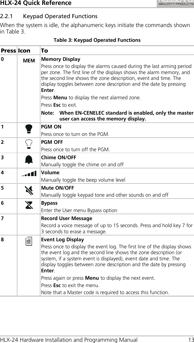
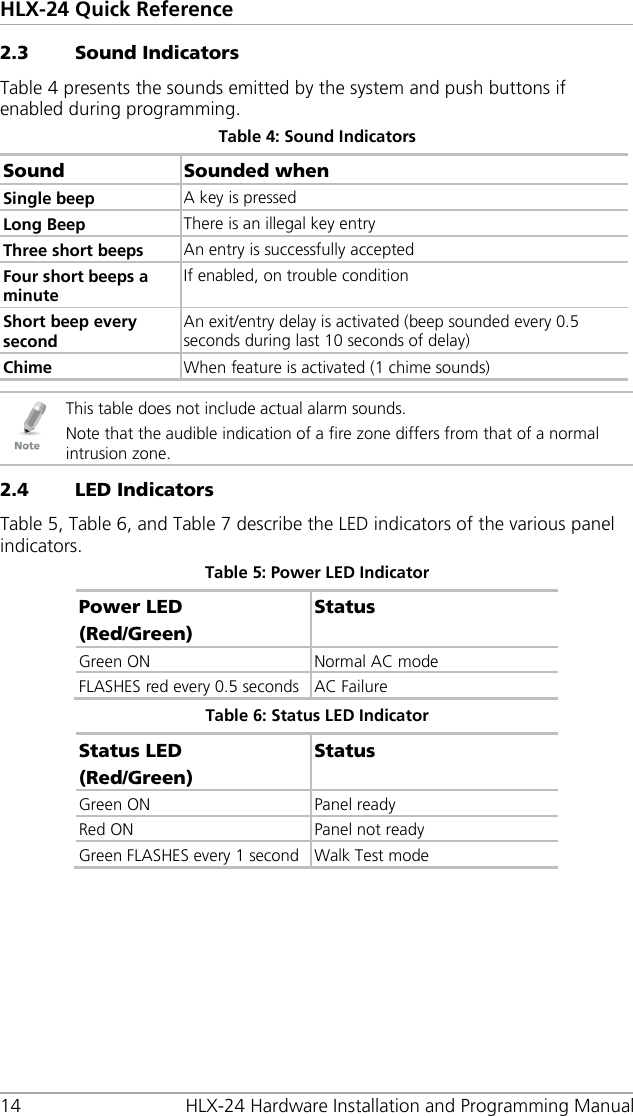
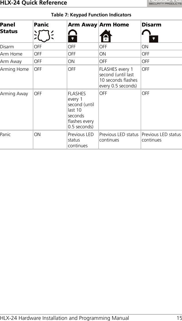
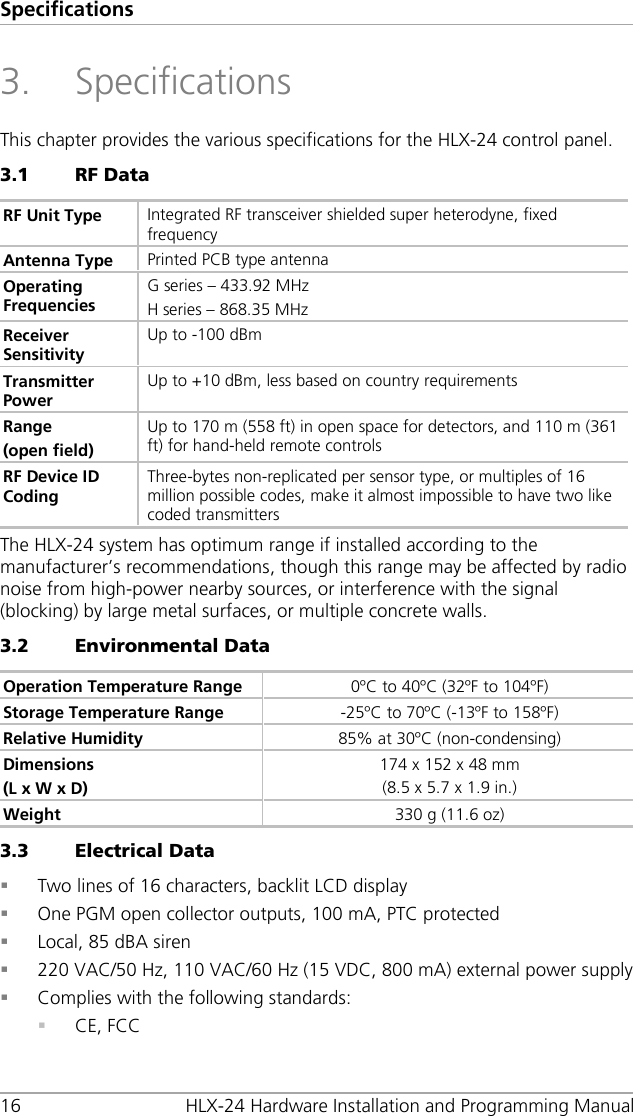
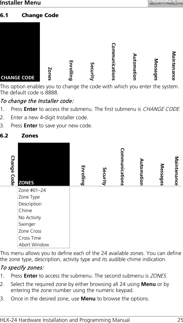
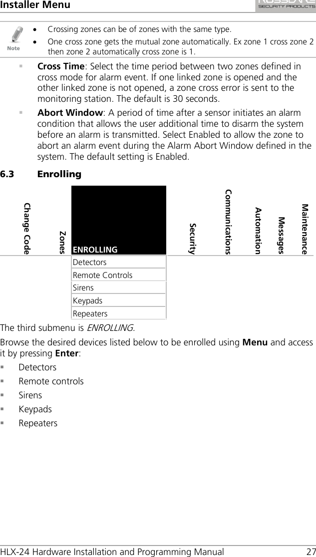
User Manual
Discussion / Help
Navigation