SAFRAN Identity and Security MAVPDUAL Biometric Recognition Terminal User Manual DRAFT MA VP User Guide
SAFRAN MORPHO Biometric Recognition Terminal DRAFT MA VP User Guide
UserManual.wiki
>
SAFRAN Identity and Security
>
MAVPDUAL User Manual
User Manual
Navigation menu
Upload a User Manual
Namespaces
Wiki Guide
HTML
PDF
Info
Views
User Manual
Discussion / Help
Navigation

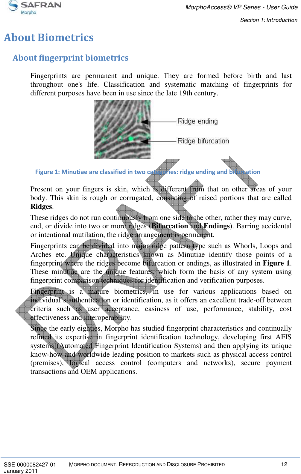
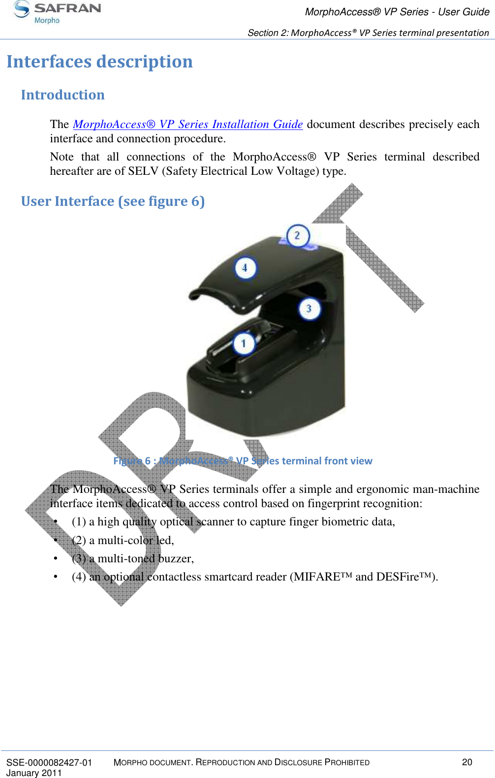
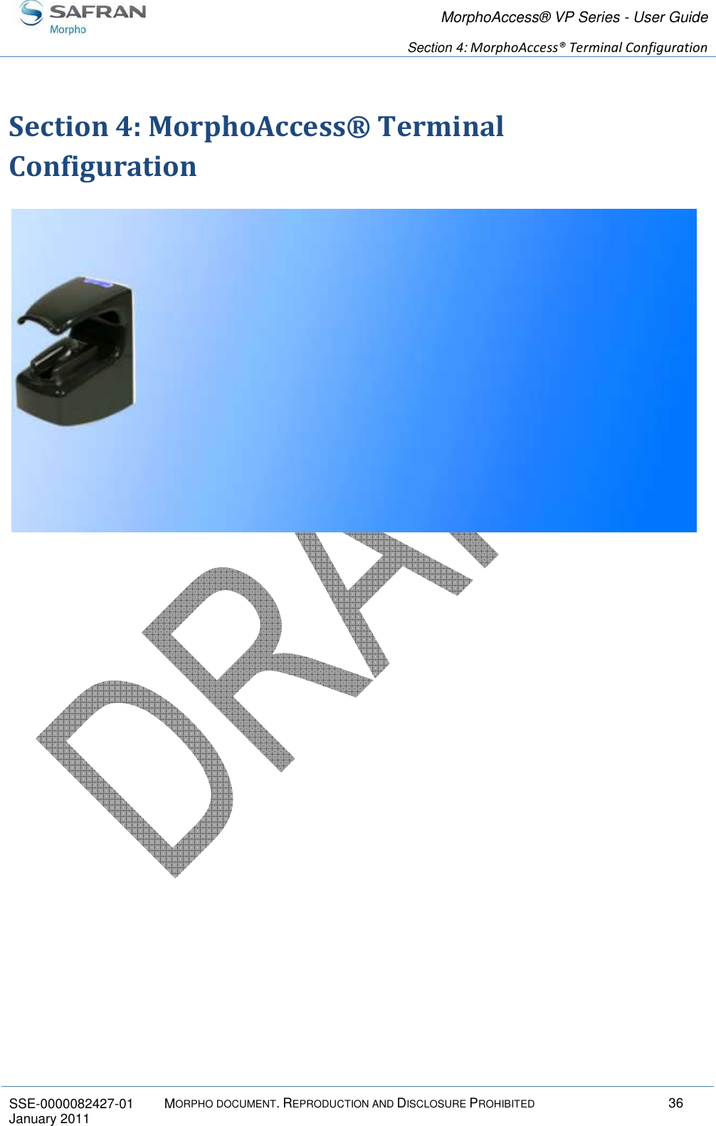
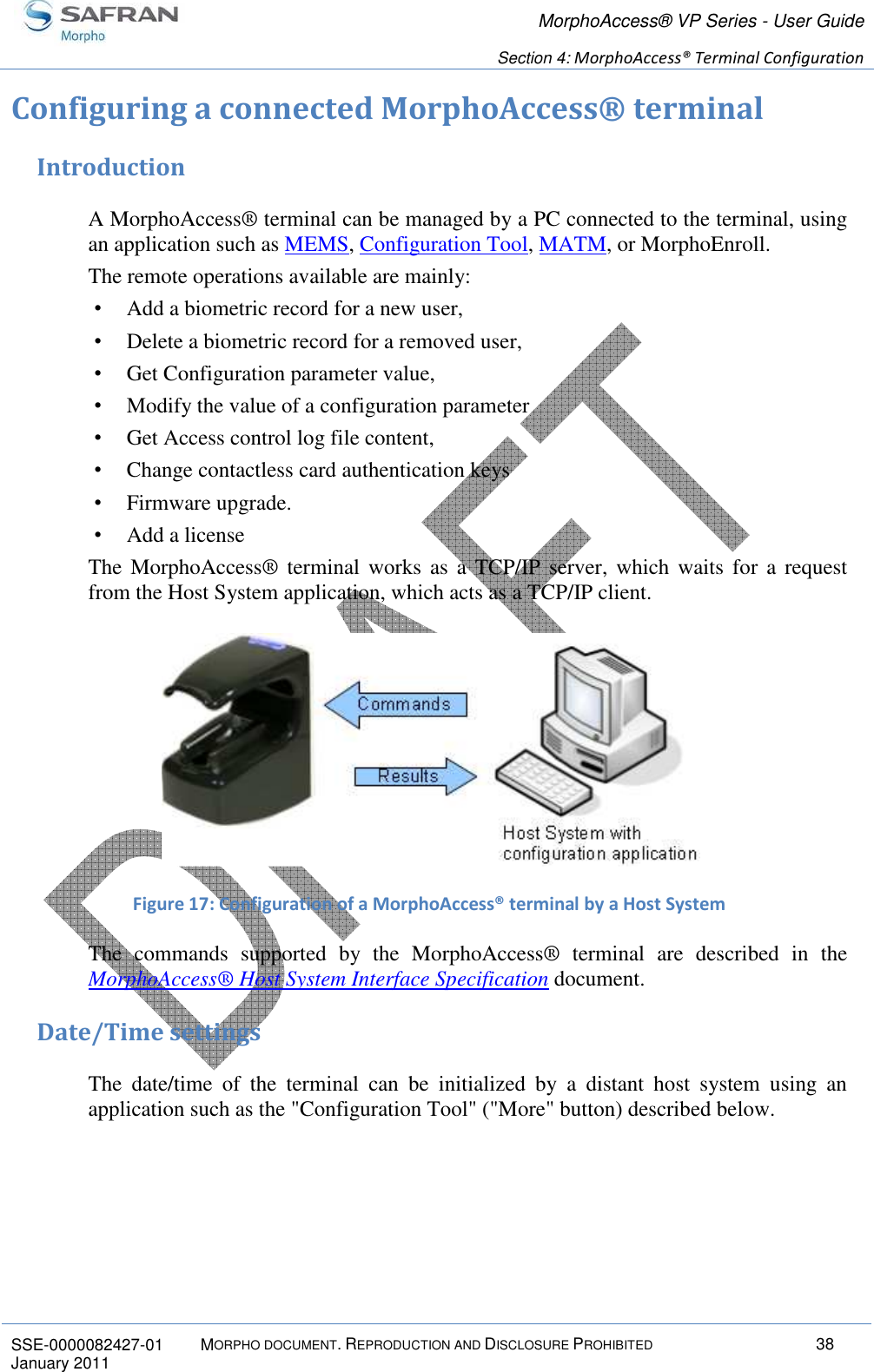

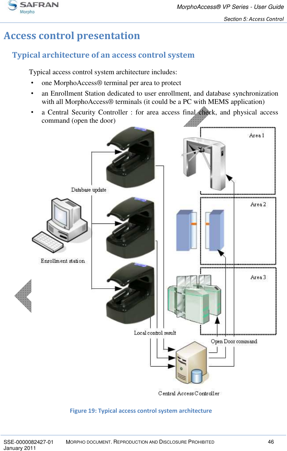
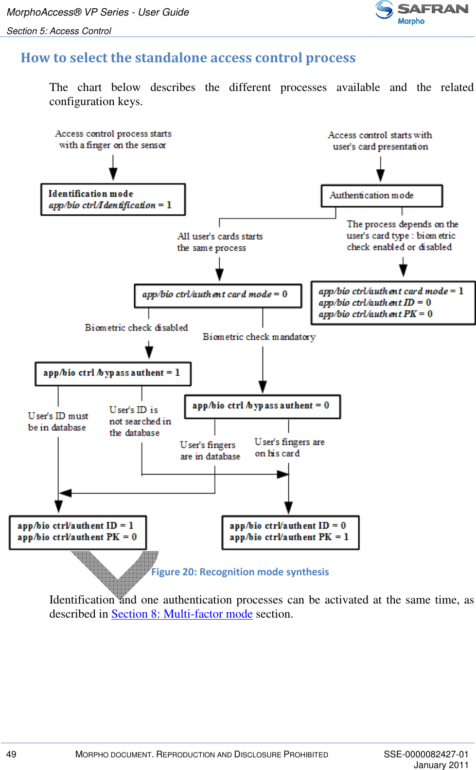

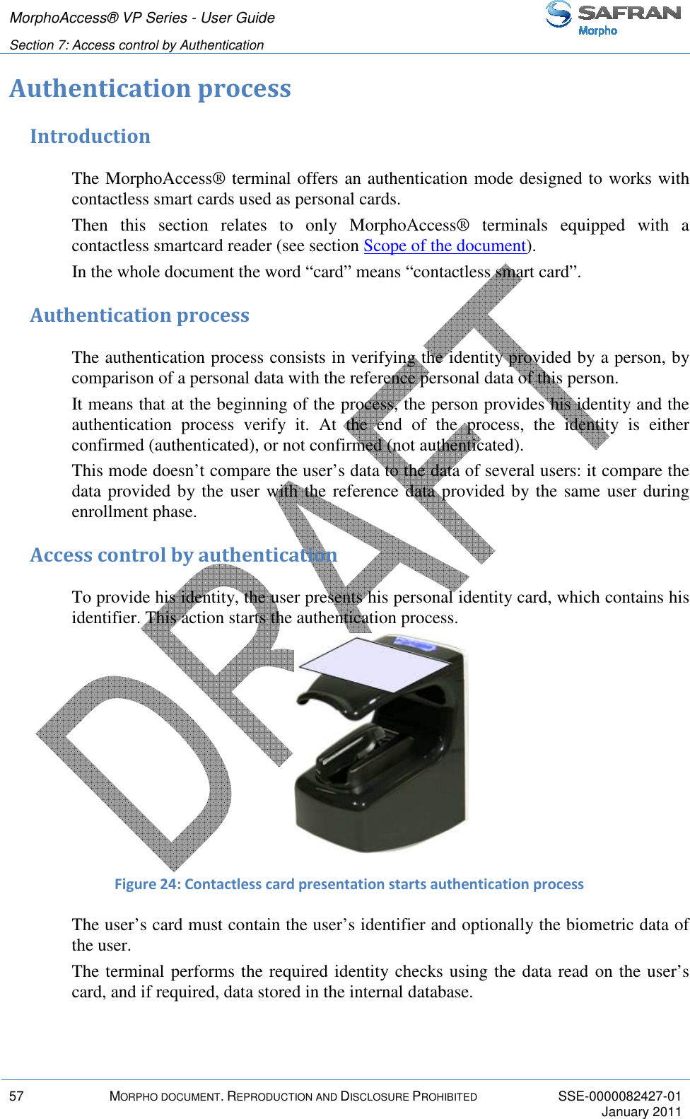
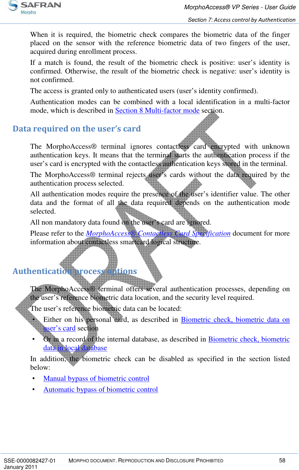
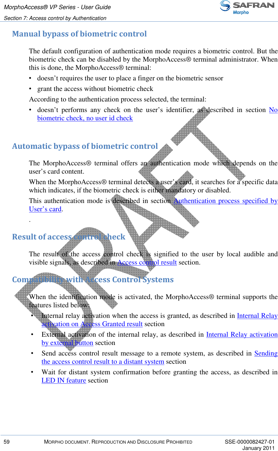
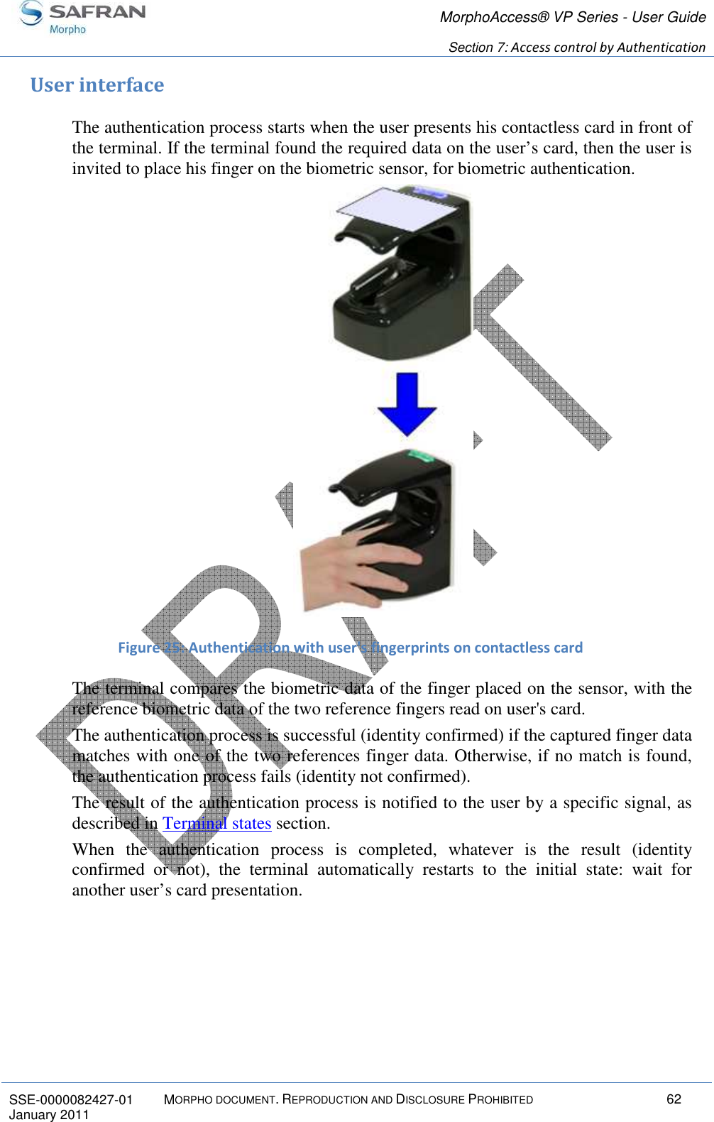
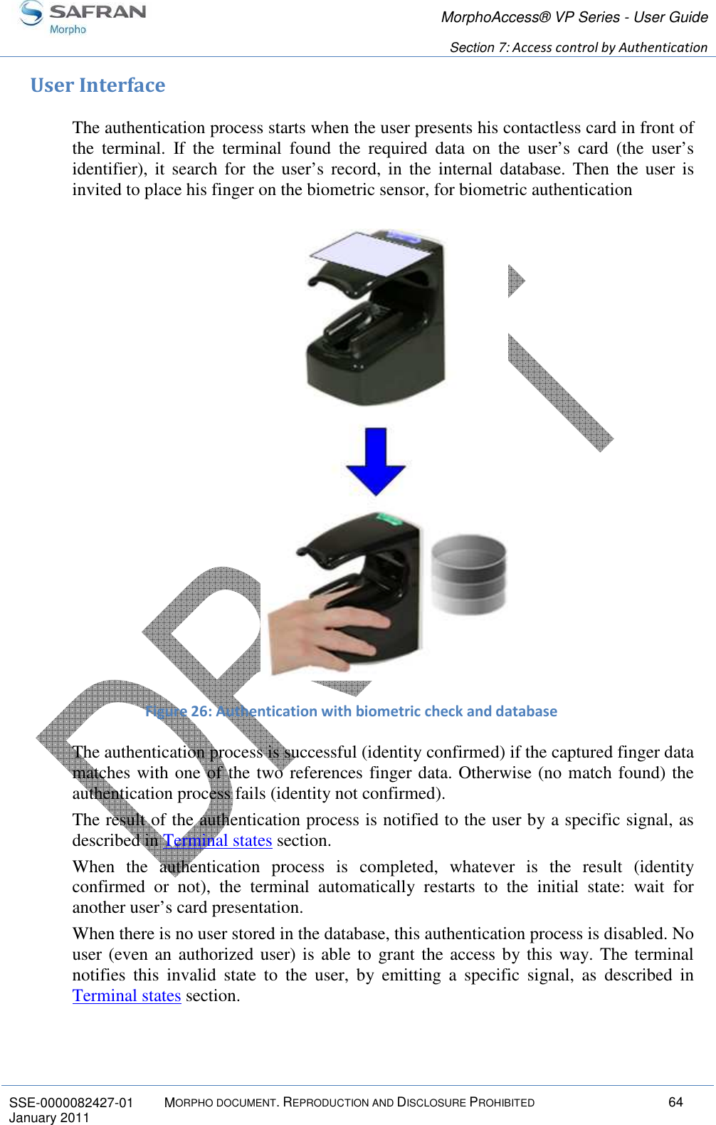
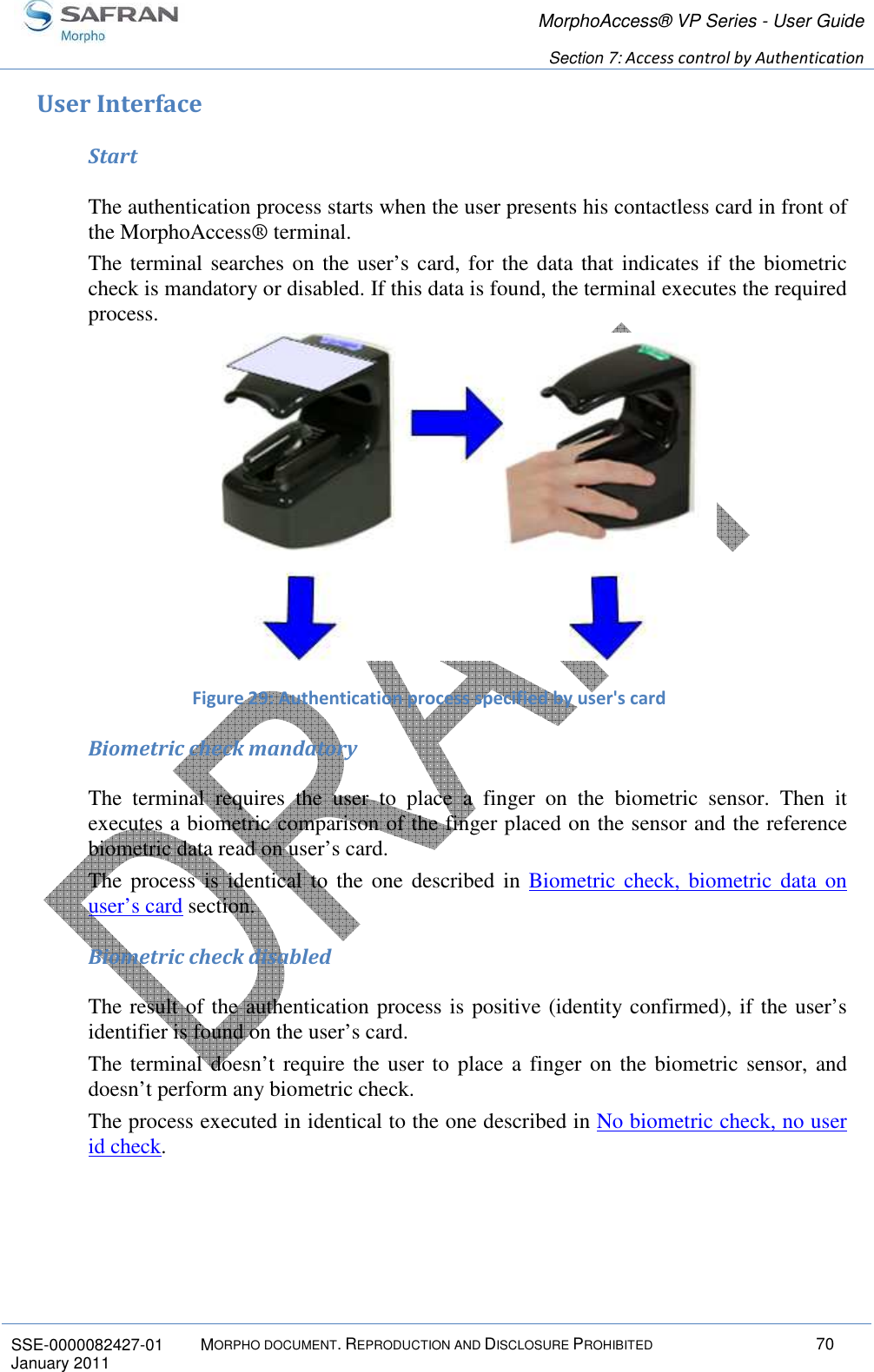
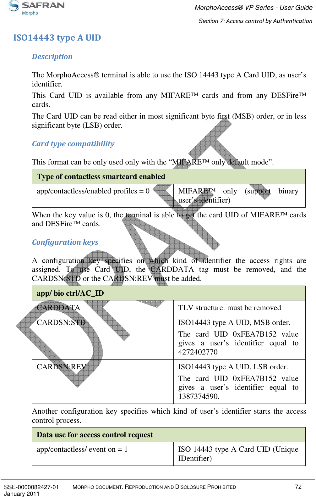
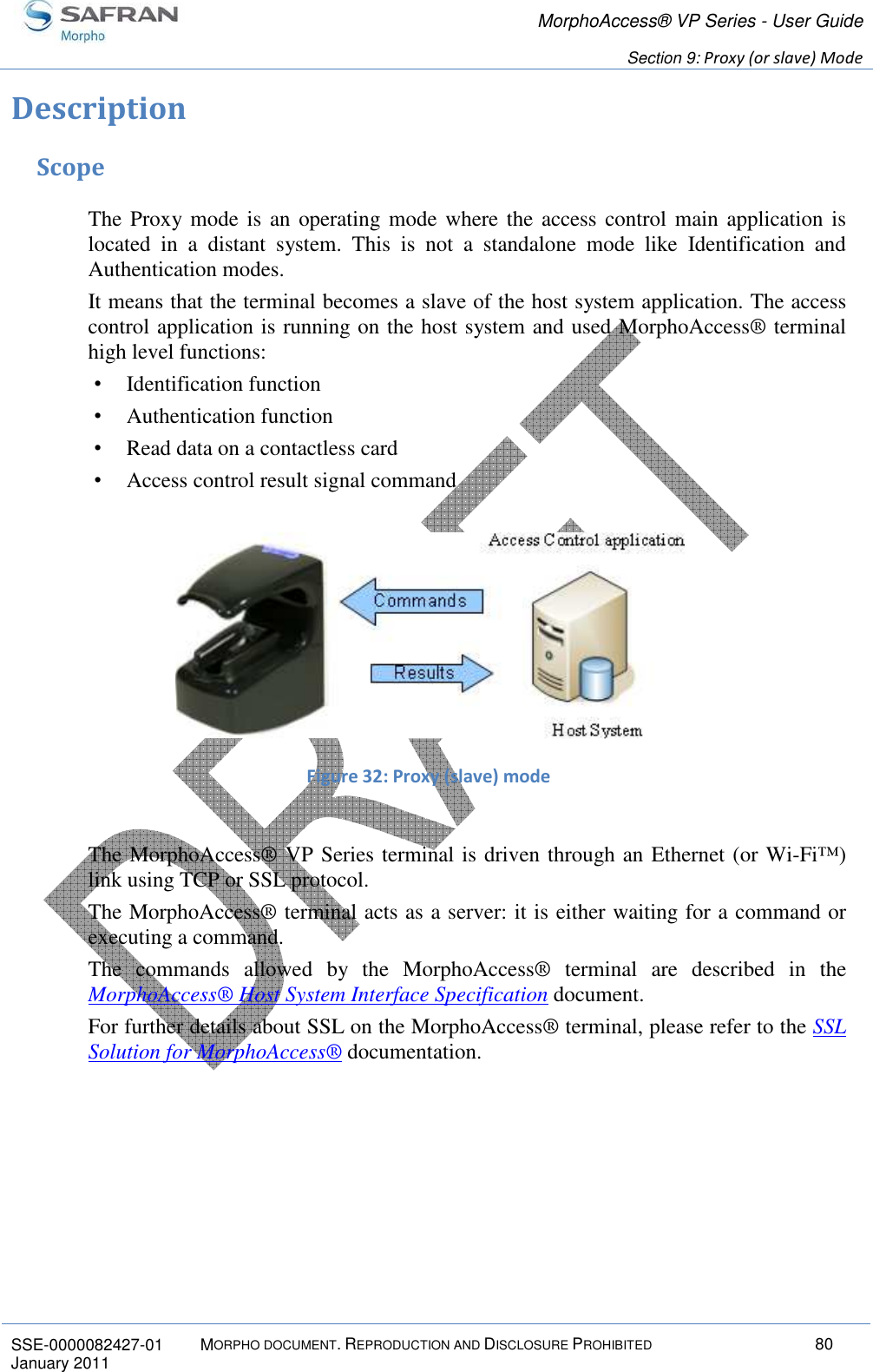
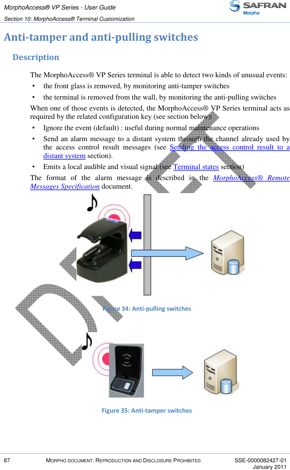
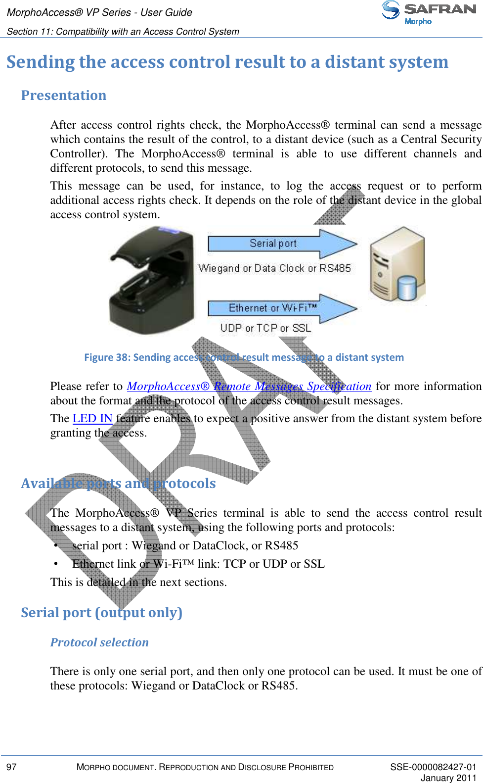
![MorphoAccess® VP Series - User Guide Section 7: Access control by Authentication 73 MORPHO DOCUMENT. REPRODUCTION AND DISCLOSURE PROHIBITED SSE-0000082427-01 January 2011 Binary data Description The MorphoAccess® terminal is able to use as user’s identified, a binary value to read on specific location on user’s card. This binary value could be the serial number of the card, as explained in the Example: MIFARE™ card Serial Number used as user’s identifier section. The MorphoAccess® terminal is able to read a binary value which is not aligned on complete bytes. This ability is useful to extract the user’s identifier from a Wiegand frame written on the user’s card. A sample is described in Example: 32 bits user’s identifier within a 37-bits Wiegand frame section. No TLV structure is required on user’s card: the MorphoAccess® terminal is able to use user’s cards written by other systems. Card type compatibility This format can be only used only with the “MIFARE™ only default mode”. Type of contactless smartcard enabled app/contactless/enabled profiles = 0 MIFARE™ only (support binary user’s identifier) Configuration keys The binary data to read is data defined by: • The offset of the first block which contains the data • The offset of the first byte/bit of the data, within the sector (15 bytes maximum). The terminal is able to read a user’s identifier which offset is different from a multiple of 8 bits. • The length (in bytes and bits) of the data (8 bytes maximum). The terminal is able to read a user’s identifier which length is different from a multiple of 8 bits. • The read direction (MSB or LSB) User’s identifier stored in ASCII format app/contactless/dataformat = 1 Binary format app/contactless/B [1-215] First block to read on card app/contactless/data length [number of bytes].[additional bits] User ID length in bytes and additional bits (8 bytes maximum) app/contactless/data offset [number of Location of first byte/bit of the user’s](https://usermanual.wiki/SAFRAN-Identity-and-Security/MAVPDUAL/User-Guide-1445307-Page-73.png)
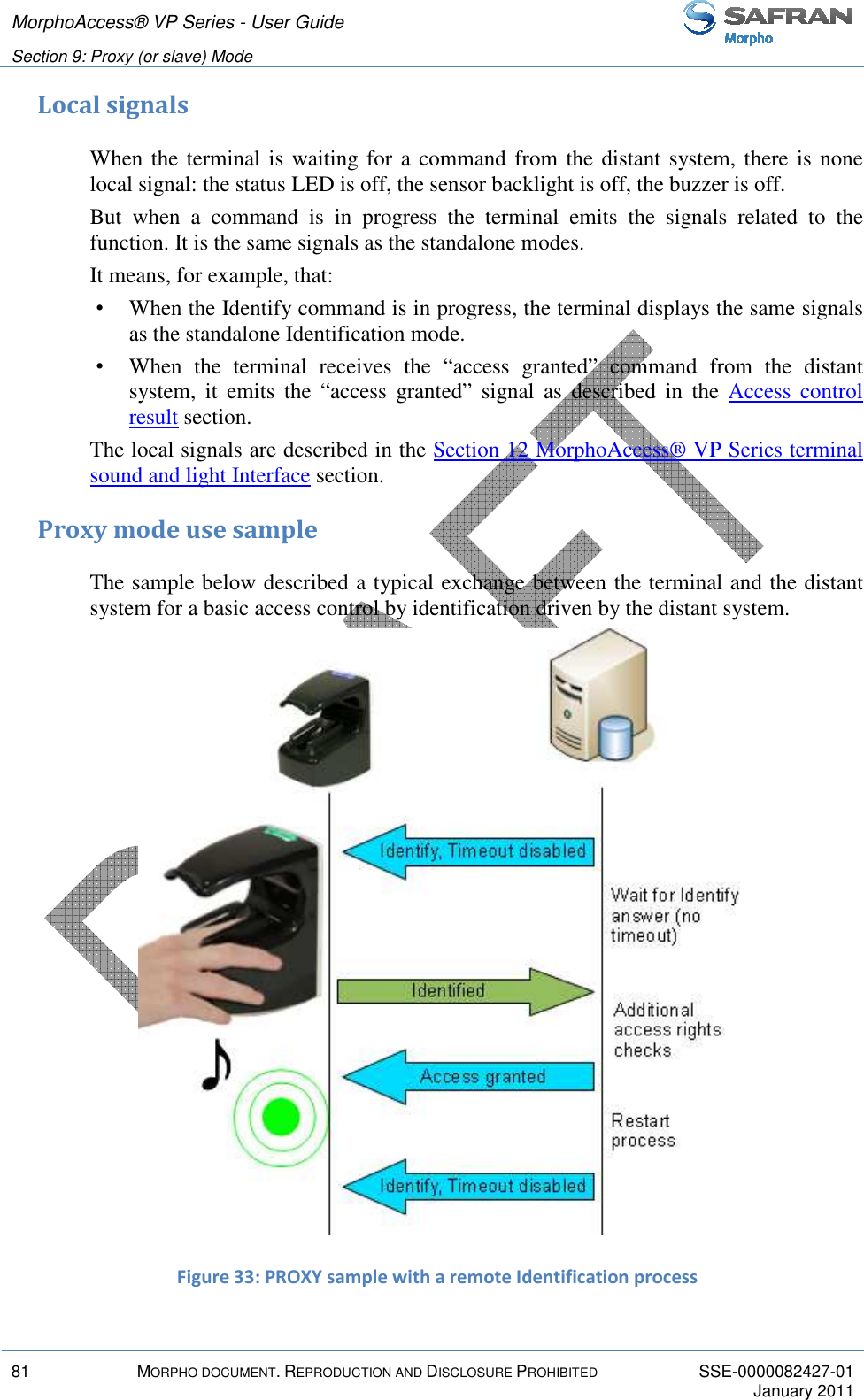
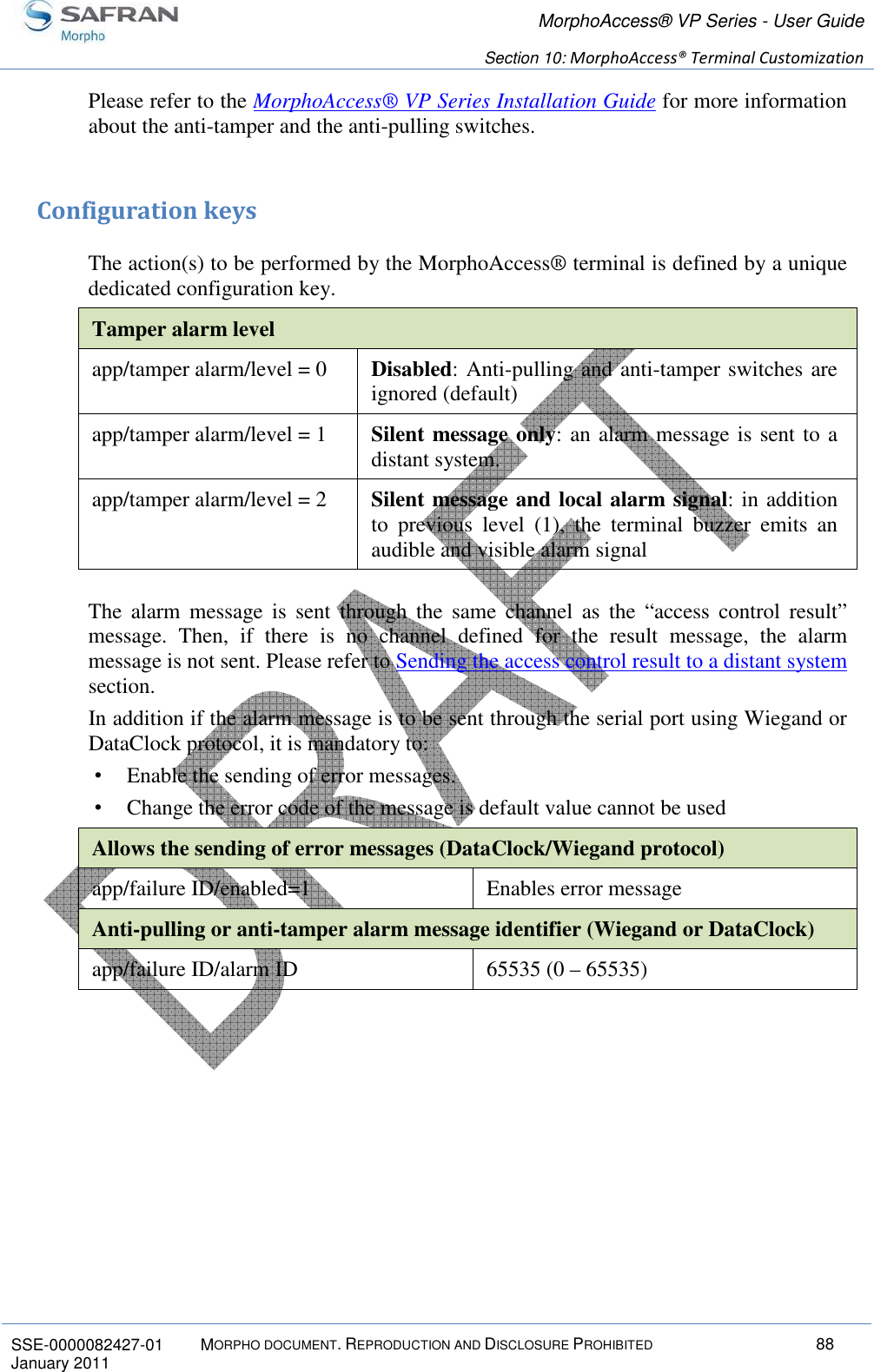
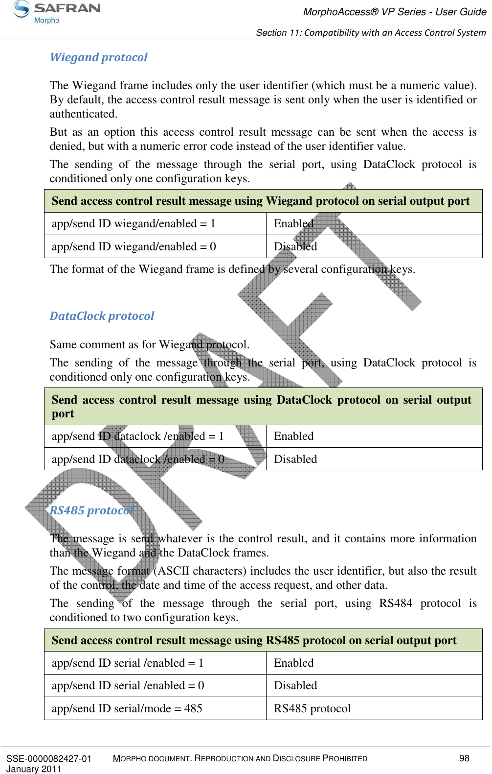
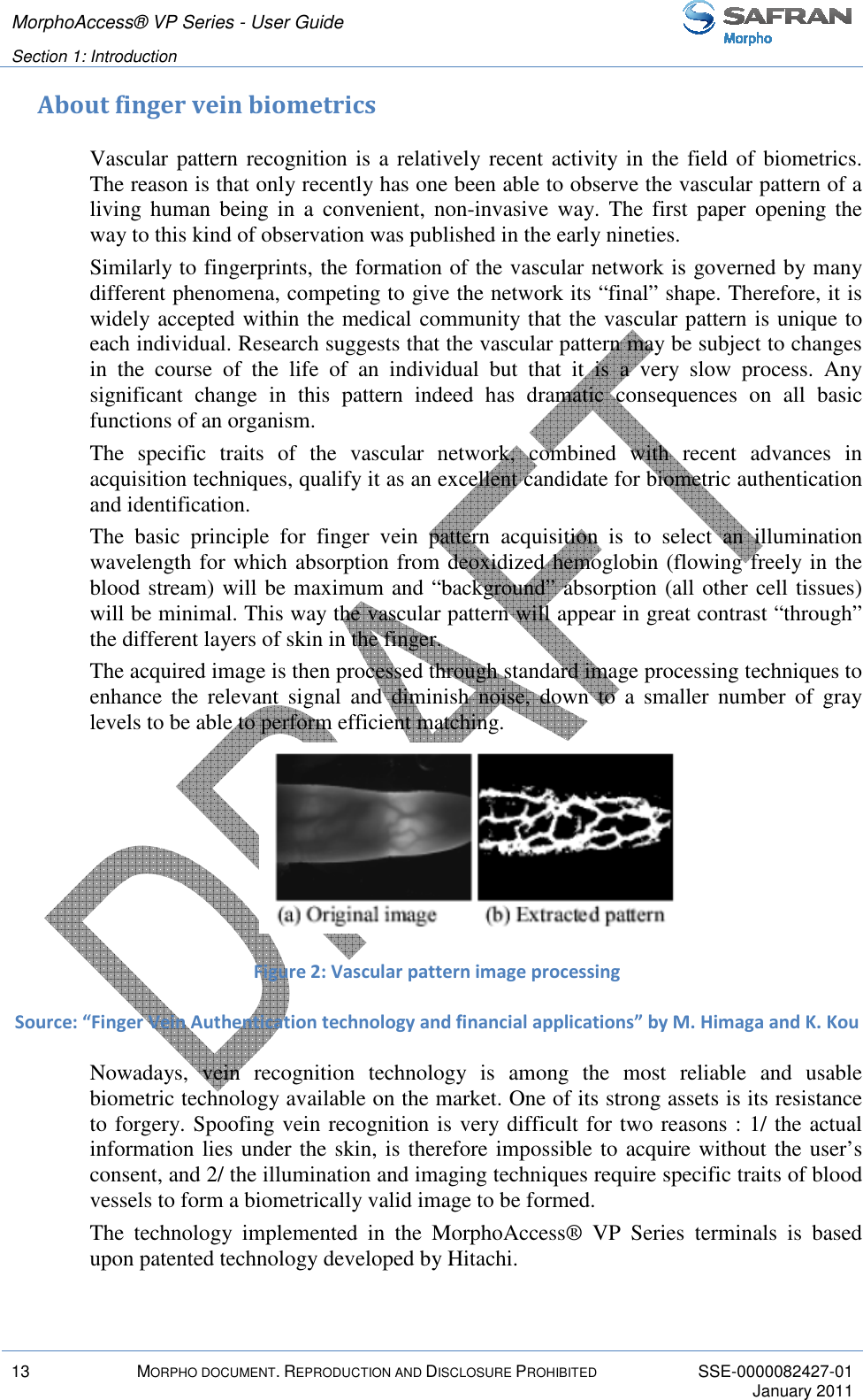
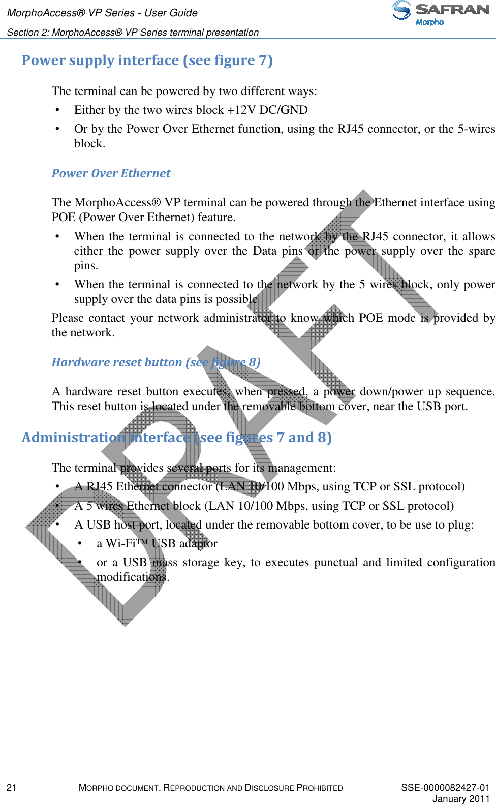
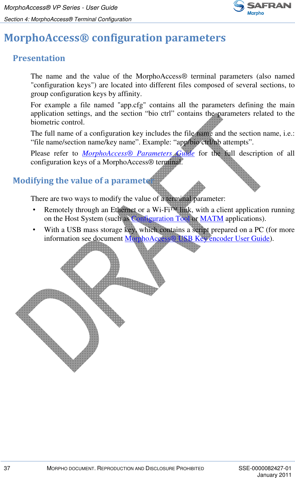
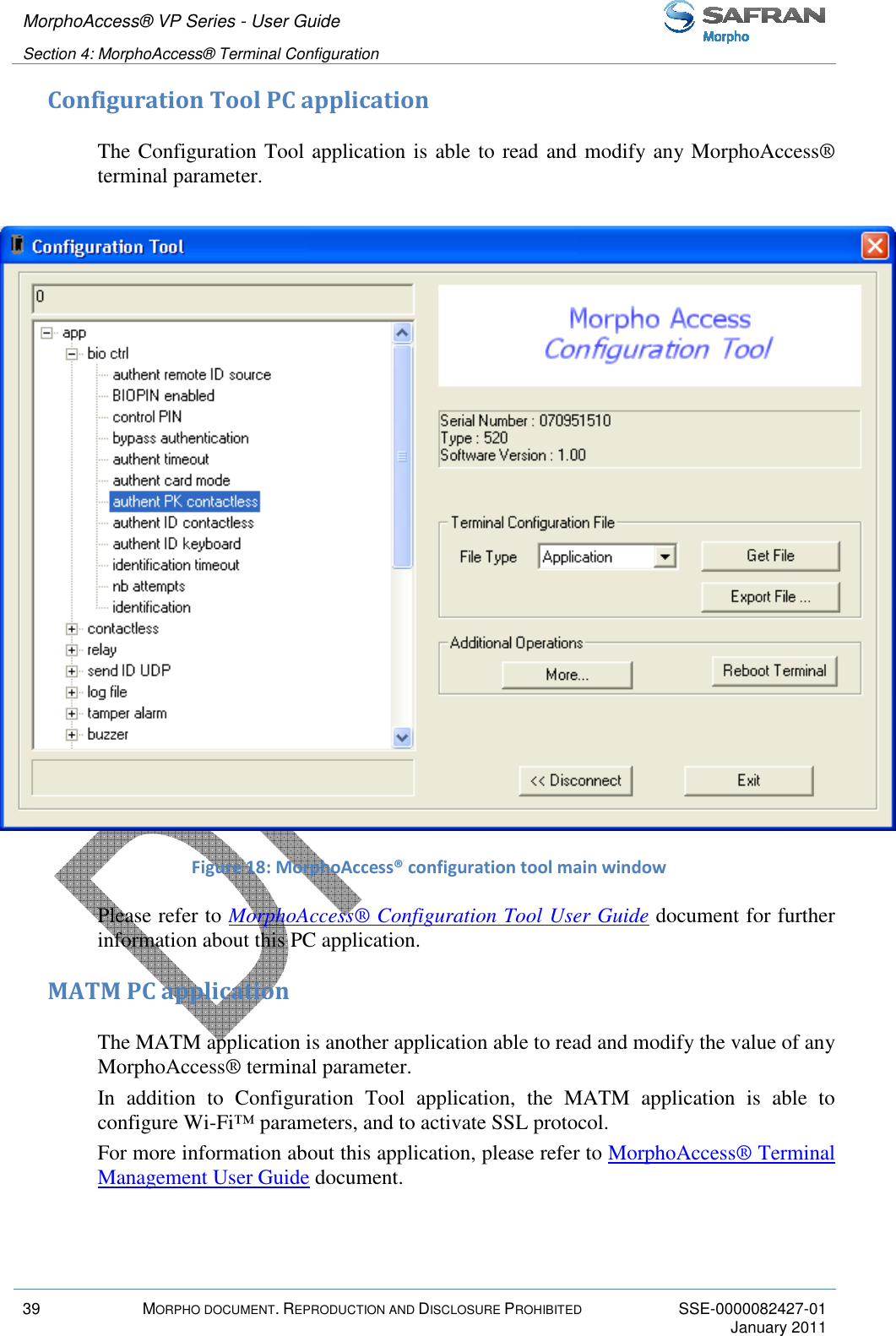
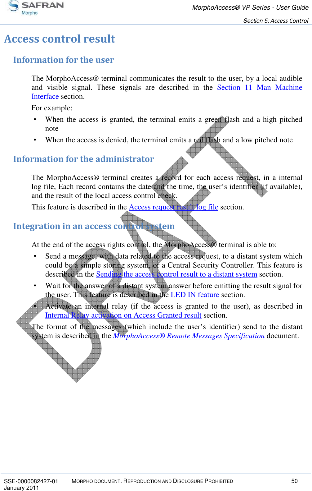
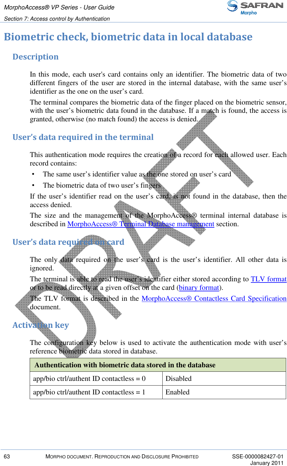
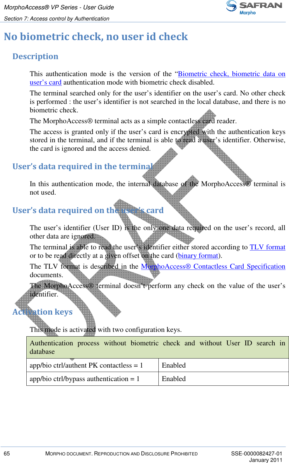
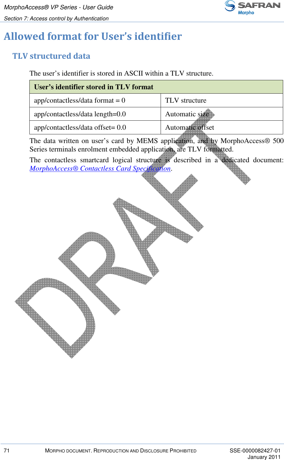
![SSE-0000082427-01 MORPHO DOCUMENTJanuary 2011 bytes].[additional bits] app/contactless/data type Example: MIFARE™ card Serial Number used as user’s identifierIn this sample the terminal read the first four byte, in MSB direction, of the first sector of the MIFARE™ card which contains the serial number of the card.If bytes to read are (ASCII). Activation of identification modeapp/contactless/data format= 1app/contactless/data type= 0.1app/contactless/data length = 4.0app/contactless/data offset= 0.0app/contactless/B= 1Example: 32 bits user’s identifier The user’s card contains(which includes start and stopFigure 30 : Sample of user’s identifier which is The 32 bits identifier begins at bit four. It is located after the start bit (bit0) and the site code (bit1-2-3). The first block of sector #15 is block #46.Acquisition of a 32 bits user’s identifier inside a 37 bits Wiegand frameapp/contactless/data format= 1app/contactless/data type= 0.1MorphoAccess® VP Series Section 7: Access control by AuthenticationDOCUMENT. REPRODUCTION AND DISCLOSURE PROHIBITED bytes].[additional bits] identifier (15 bytes maximum)app/contactless/data type Byte read acquisition little or big endian. 0.1 (binary data, MSB first)0.0 (binary data, LSB first)MIFARE™ card Serial Number used as user’s identifierIn this sample the terminal read the first four byte, in MSB direction, of the first sector of the MIFARE™ card which contains the serial number of the card.are F4 E1 65 34, then the user identifier value Activation of identification mode app/contactless/data format= 1 Binary format app/contactless/data type= 0.1 Binary MSB format app/contactless/data length = 4.0 Size = 4 bytes, no additional bitapp/contactless/data offset= 0.0 First byte of the blockapp/contactless/B= 1 First block of the card32 bits user’s identifier within a 37-bits Wiegand framecard contains, at the first block of sector 15 a full 37 bits Wiegand frame start and stop bits, the site code of the sender, and user’s identifierample of user’s identifier which is included in a Wiegand frameidentifier begins at bit four. It is located after the start bit (bit0) and the site 3). The first block of sector #15 is block #46. Acquisition of a 32 bits user’s identifier inside a 37 bits Wiegand frameapp/contactless/data format= 1 Binary format app/contactless/data type= 0.1 Binary identifier, MSB formatMorphoAccess® VP Series - User Guide Access control by Authentication 74 identifier (15 bytes maximum) acquisition method: either 0.1 (binary data, MSB first) LSB first) MIFARE™ card Serial Number used as user’s identifier In this sample the terminal read the first four byte, in MSB direction, of the first sector of the MIFARE™ card which contains the serial number of the card. value is "4108412212" additional bit First byte of the block First block of the card Wiegand frame 37 bits Wiegand frame , and user’s identifier). Wiegand frame identifier begins at bit four. It is located after the start bit (bit0) and the site Acquisition of a 32 bits user’s identifier inside a 37 bits Wiegand frame. Binary identifier, MSB format](https://usermanual.wiki/SAFRAN-Identity-and-Security/MAVPDUAL/User-Guide-1445307-Page-74.png)