SEA of Delaware SEA157 VHF Marine Radiotelephone/DSC Controller User Manual April 5 2000 FIRST DRAFT
SEA Inc of Delaware VHF Marine Radiotelephone/DSC Controller April 5 2000 FIRST DRAFT
UserManual.wiki
>
SEA of Delaware
>
SEA157 User Manual
ta8man users manual theory of operation and tuneup procedures
Navigation menu
Upload a User Manual
Namespaces
Wiki Guide
HTML
PDF
Info
Views
User Manual
Discussion / Help
Navigation
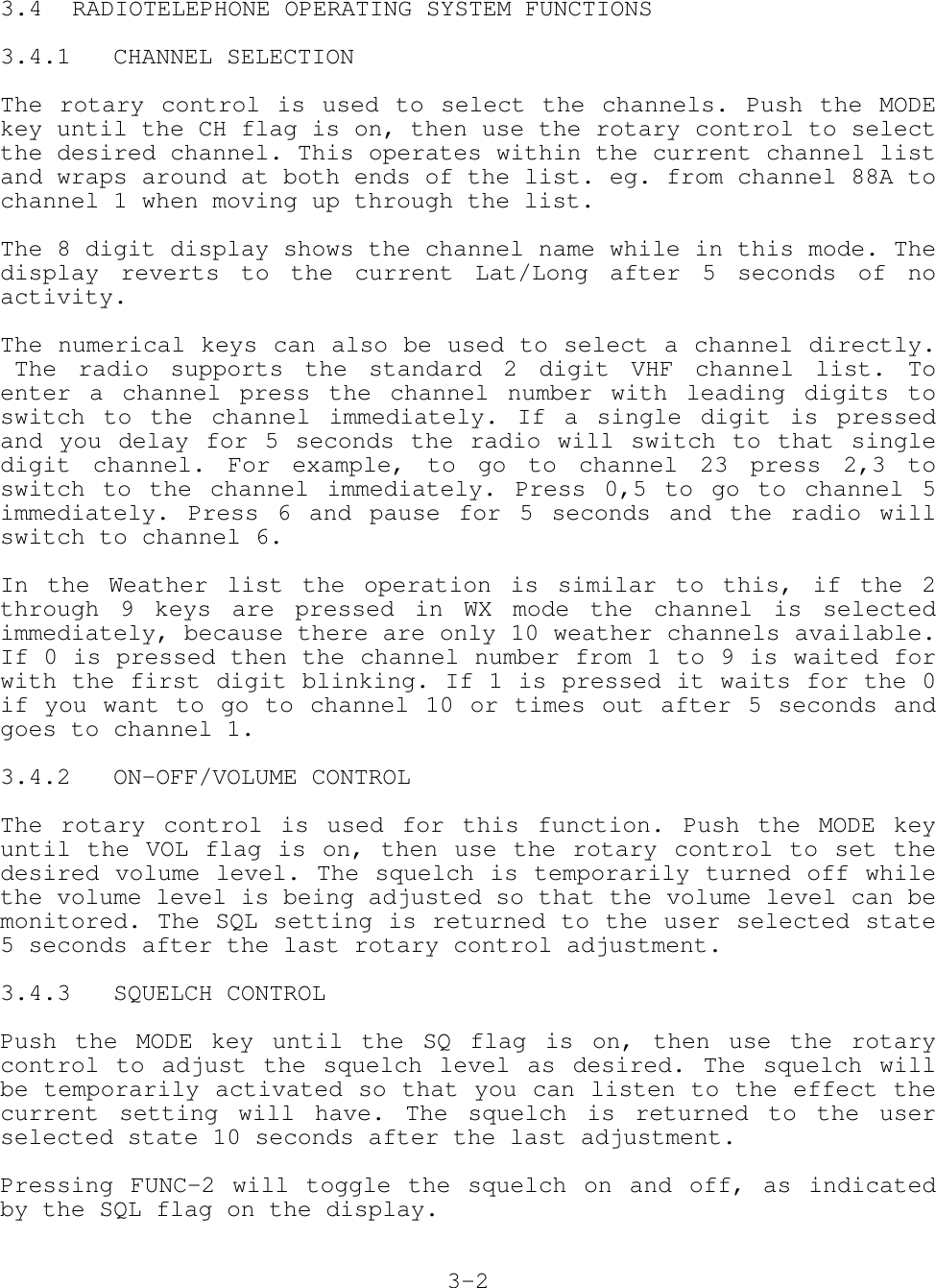
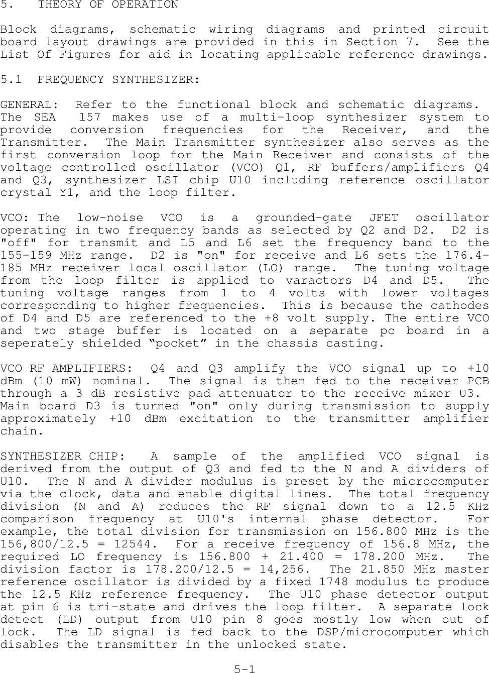
![3.4.4 CHANNEL LIST SELECTIONPressing FUNC-8 will toggle the radio between the USA and INTchannel lists. The radio will go to the last used channel in theselected list. If it is pressed while in the Weather list it willreturn to the previous list.Pressing FUNC-3 will switch the radio to the weather list,remembering the current list and channel. Pressing FUNC-3 againwill return the radio to the previous channel list and channel.3.4.5 EMERGENCY CHANNEL SELECTIONPushing the CH16 key at any time, in any state of radio operation,will go to CH16 in the current list, or in the case of pressing itwhile in the Weather list it will go to CH 16 in the last usedlist.3.4.6 TRANSMITTER POWER CONTROLPressing FUNC-1 toggles the transmitter power level on channelsthat allow 25W transmission. On channels that only allow 1W thisfunction does nothing. When transmitting on a 1W only channel theFUNC key can be held down while transmitting to temporarily switchto 25W. The display will show the 1W flag when in the 1W mode andthe 1W flag will be off when 25W is active.3.4.7 DUAL WATCHThe SEA 157 has two watch modes available. Dual watch is initiatedby pressing FUNC-6 briefly while on the primary channel you wantto monitor. The 8 character display will say 'DUAL 16' and channel16 will be checked every 2 seconds while there is no activity oneither channel. If there is activity on the primary channel or onchannel 16 the radio will hold on that channel until there is noactivity for [hangtime] seconds. This behavior can be changed sothat channel 16 always has priority by using the Dual Watch setupmenu option.The channel number display will indicate which channel it isoperating on. Pressing PTT will exit dual watch and switch to thecurrent channel.If Dual Watch is selected while on channel 16 it will not start adual watch.The Triple Watch function is started by pressing FUNC-6 for longerthan 1 second on the primary channel that you want to monitor. Thedisplay will show 'TRIPL 16' and will check channel 16 and thePriority channel every 2 seconds. By default channel 16 haspriority, but this behavior can be changed using the Triple Watchsetup menu option.3-3](https://usermanual.wiki/SEA-of-Delaware/SEA157/User-Guide-96111-Page-13.png)
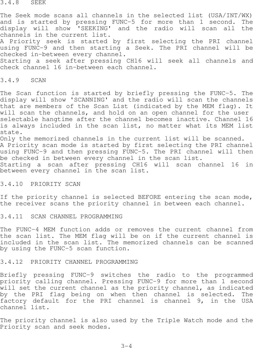
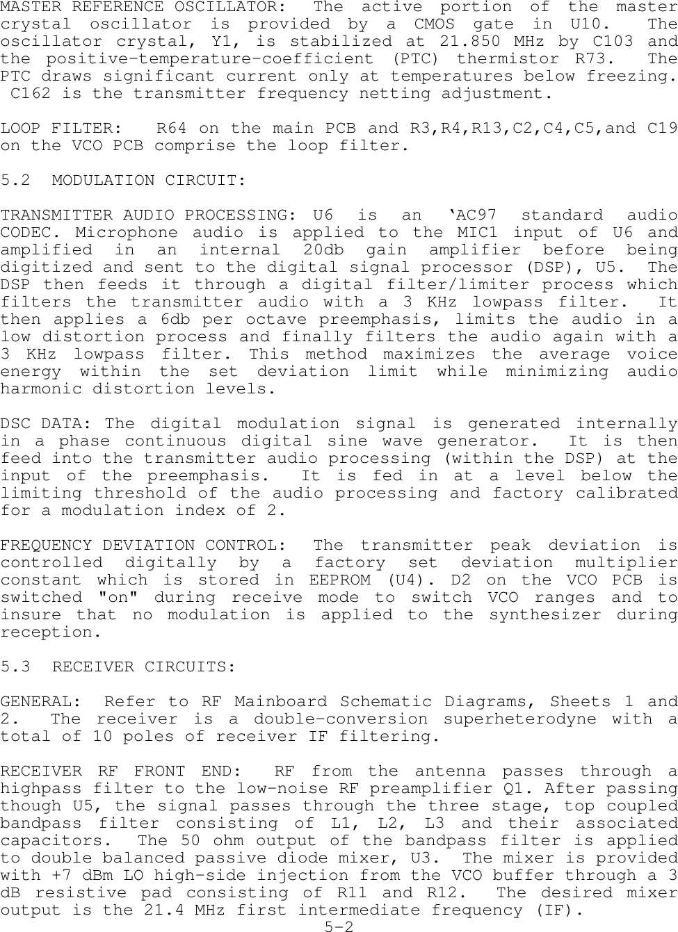
![3.4.13 SEARCH MODE PROGRAMMINGEnter the setup menu using FUNC-MODE and then select the ‘SEARCH’function with the rotary control. Press MODE to adjust the searchmode operation. Use the rotary control to select from 2 styles ofsearch mode operation for Seek and Scan modes:[ACt]1 - Stop on the active channel until squelch closes[ gO]2 - Stop on the active channel for 2.5 seconds and thencontinue the search.3.4.16 PRIORITY/DUAL SCAN MODE PROGRAMMINGEnter the setup menu using FUNC-MODE and then select the‘DUALWTCH’ function with the rotary control. Press MODE to adjustthe Dual Watch mode operation. Use the rotary control to selectfrom 2 styles of dual watch:[ACt]1 - Stop on first active channel[C16]2 - CH 16 always has priority, and is checked even when thereis activity on other channels3.4.17 SCAN HANG TIME PROGRAMMINGEnter the setup menu using FUNC-MODE and then select the‘HANGTIME’ function with the rotary control. Press MODE to adjustthe hangtime. Use the rotary control to select the amount of timefor the radio to stay on a channel after the squelch closes, in0.5 second increments from 0 to 20 on the display (0 to 10seconds).3.4.18 ADJUSTING THE BACKLIGHTING LEVELPush the MODE key until the DIM flag is on, then use the rotarycontrol to adjust the brightness level. The display will show thebrightness level.3.4.19 KEY BEEP CONTROLEnter the setup menu using FUNC-MODE and then select the ‘BEEPLVL’ function with the rotary control. Press MODE to adjust thebeep level. Use the rotary control to select the beep volumelevel, 0-15. The radio will emit a short test beep for every turnof the rotary control.3.4.21 MODIFYING CHANNEL NAMESSelect the channel to be edited using the rotary control or directchannel entry. The channel’s current ASCII tag will be displayedfor 3 seconds. Select the channel editing function by pressingFUNC-MODE and selecting the ‘CHANNAME’ option. Press MODE to editthe ASCII tag for the channel. The display shows the current radio3-5](https://usermanual.wiki/SEA-of-Delaware/SEA157/User-Guide-96111-Page-15.png)