SUZHOU FOIF RTS102 Total Station User Manual RTS100RTS100R V1 1
SUZHOU FOIF CO.,LTD Total Station RTS100RTS100R V1 1
UserManual.wiki
>
SUZHOU FOIF
>
RTS102 User Manual
Users Manual
Navigation menu
Upload a User Manual
Namespaces
Wiki Guide
HTML
PDF
Info
Views
User Manual
Discussion / Help
Navigation
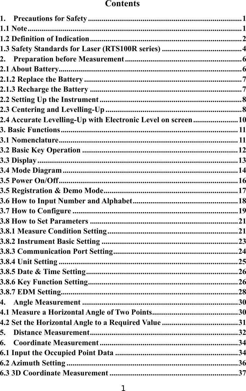
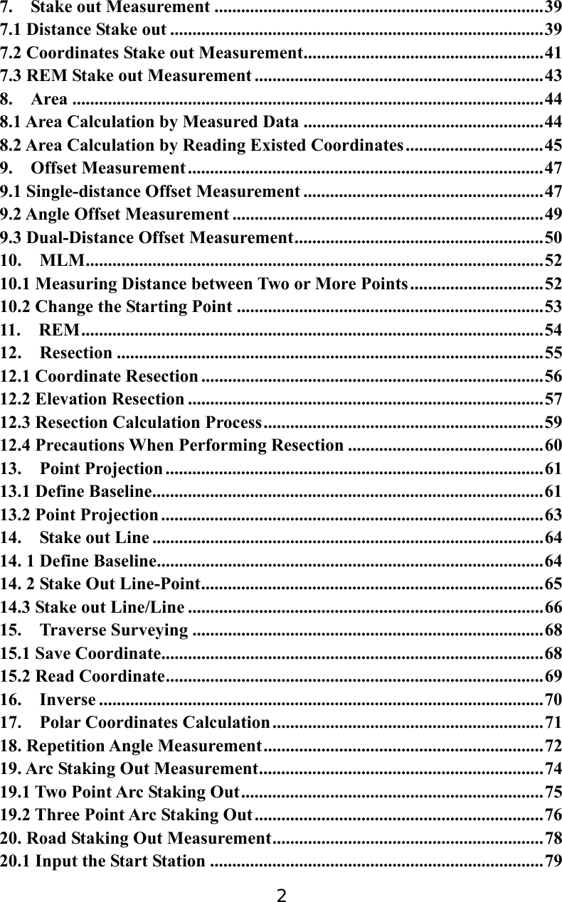

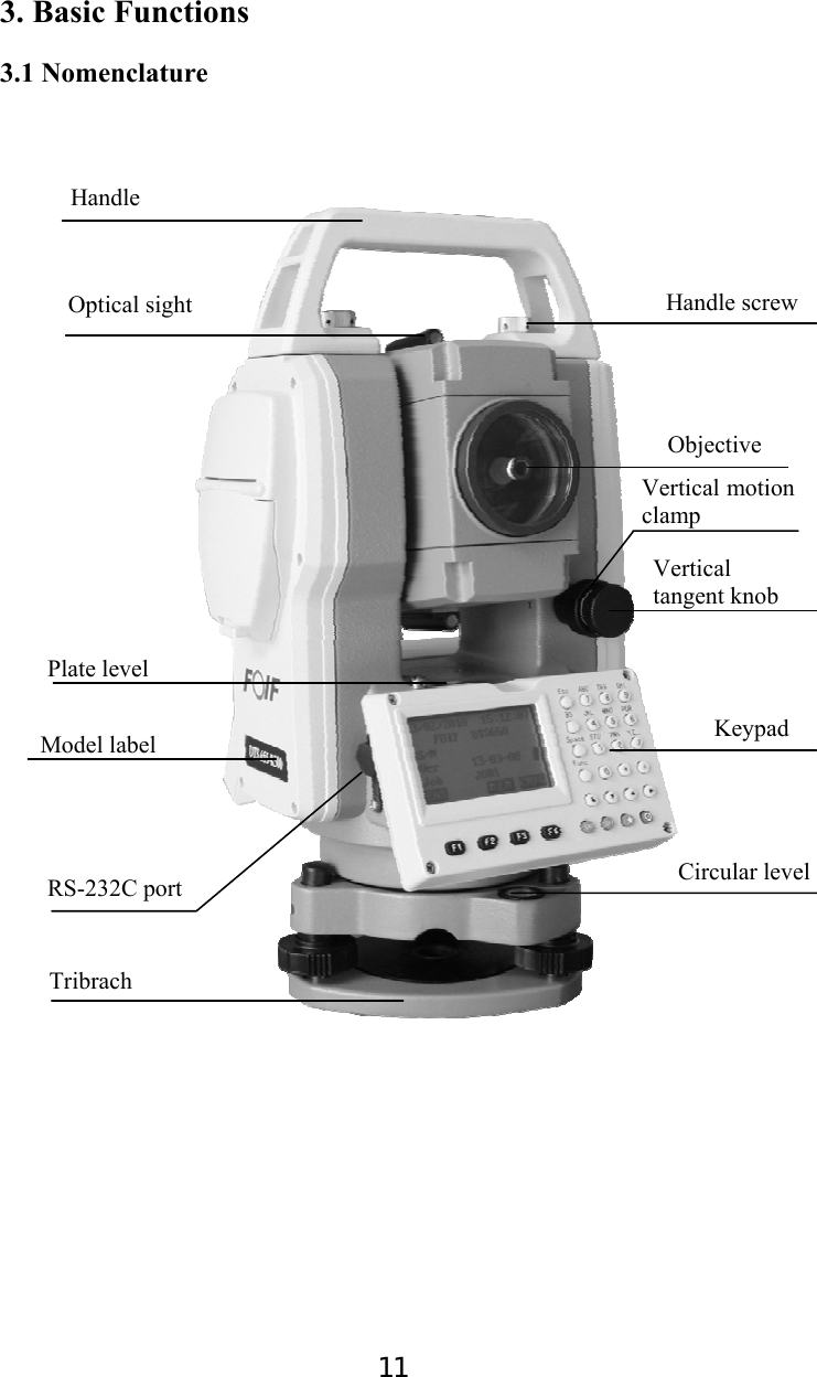
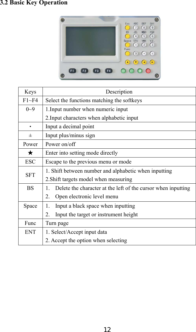
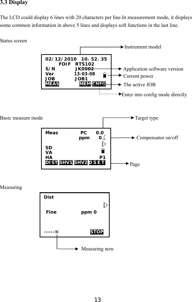
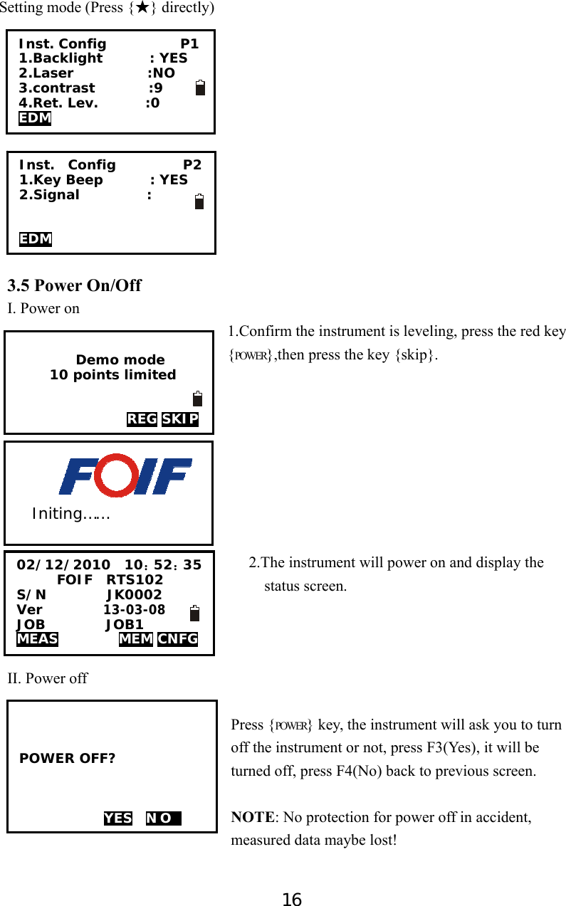
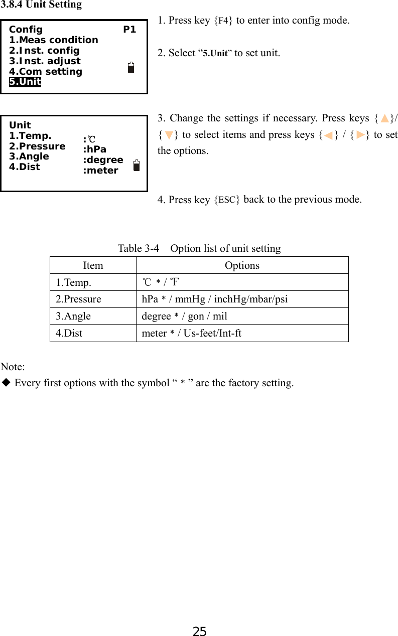
![14 [MENU] [REC] 3.4 Mode Diagram Meas mode [Func] [Func] [Func] JOB P2 1.File copy {2} {1} JOB P1 1.JOB select 2.JOB rename 3.JOB delete 4.Download 5.Com setting {ESC} [MEAS] REC JOB1 P1 1.Occ. data 2.Angle data 3.Coord data 4.dist data 5.Note EDM OCC OFST REC [MEM] {ESC} Memory 1.JOB 2.Known data 3.Code 4.Storage Media 5.USB Menu P2 1.REM 2.Resection 3.Point Projection 4.Line stake out 5.Traverse 02/12/2010 10:52:35 FOIF RTS102 S/N JK0002 Ver 13-03-08 JOB JOB1 MEAS MEM CNFG CORD MENU HOLD H S E T Known data JOB 1 1.Key input 2.Com input 3.Delete 4.View 5.Clear Meas PC 0.0 ppm 0⊥ SD VA HA P1 DIST SHV1 SHV2 0 S E T +Known data JOB 1 6.Com setting REC JOB1 P2 1.View 2.JOB select [Func] [Func] Menu P1 1.Coordinate 2.Stake out 3.Area 4.Offset 5.MLM](https://usermanual.wiki/SUZHOU-FOIF/RTS102/User-Guide-2520405-Page-20.png)
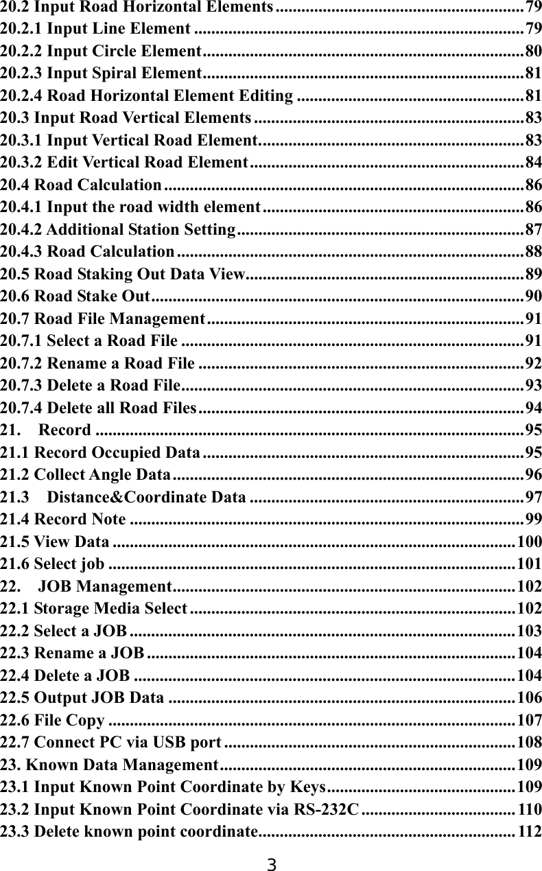
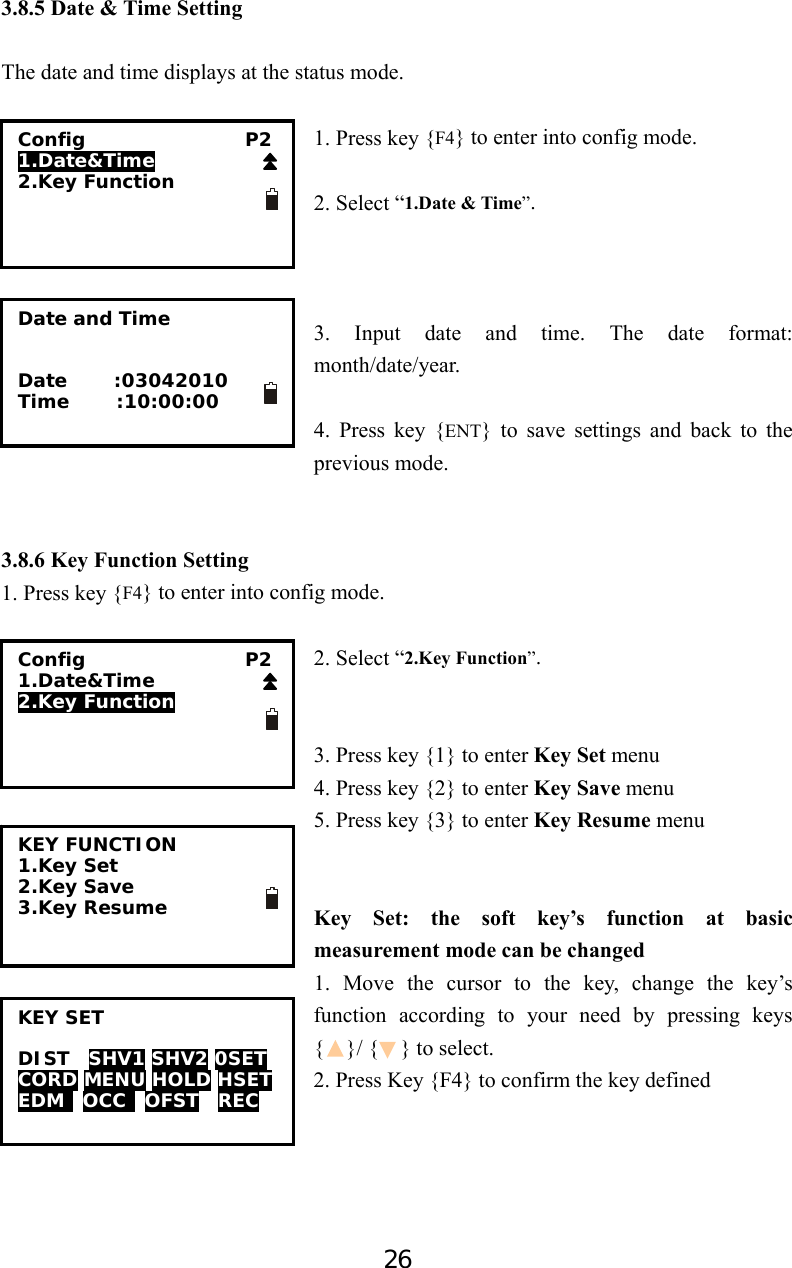
![15 Cnfg mode [Func] Config P1 1.Meas condition 2.Inst.config 3.Inst.adjust 4.Com setting 5.Unit 02/12/2010 10:52:35 FOIF RTS102 S/N JK0002 Ver 13-03-08 JOB JOB1 MEAS MEM CNFG [CNFG] {ESC} Config P2 1.Date&Time 2.Key Function Menu P3 1.Inverse 2.Polarize 3.Repeat Measure 4.Arc staking out 5.Road Calculation {3} Code 1.Code Edit 2.Clear List](https://usermanual.wiki/SUZHOU-FOIF/RTS102/User-Guide-2520405-Page-21.png)
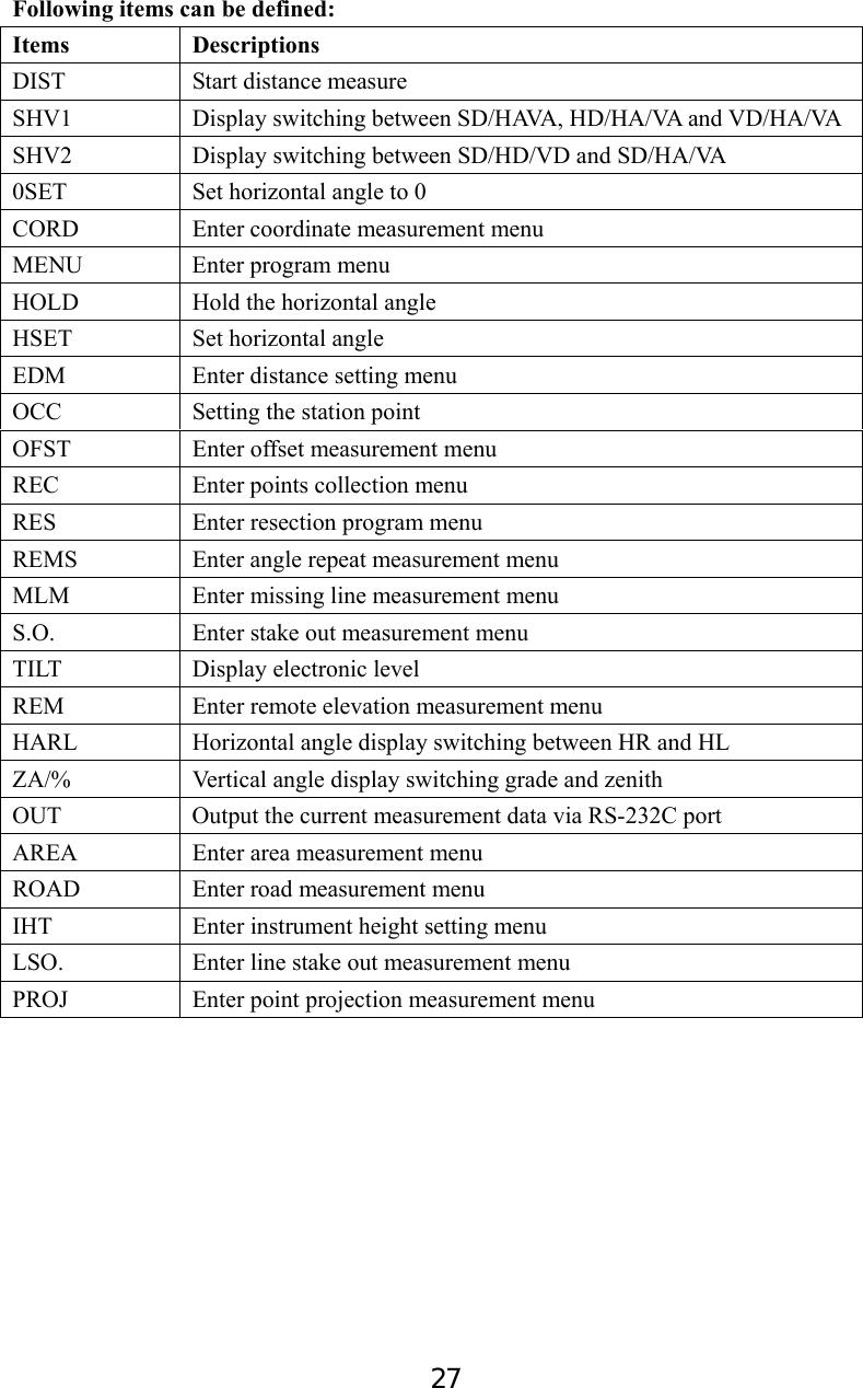
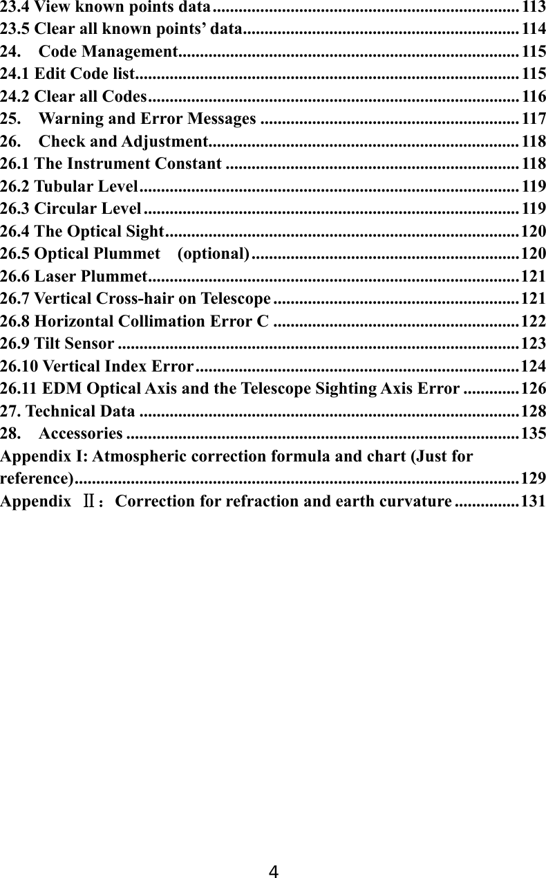
![28 Key Save 1. Press key {1} to save the current key setting in User Define 1 2. Press key {2} to save the current key setting in User Define 2 Key Resume 1. Press key {1} to resume the User Define 1 as the current Key setting 2. Press key {2} to resume the User Define 2 as the current Key setting 3. Press key {3} to resume the Default Define as the current Key setting 3.8.7 EDM Setting 1. Press F1: [MEAS] in the status mode or select to enter into measure mode. Press key {Func} to turn to page P3. 2. Press F1: [EDM] to enter into EDM setting. 3. Change the settings if necessary. Press keys { }/ { } to select the first three items and press keys { } / { } to set the options. 4. Press Func key to turn to page 2. 5. Press key {ESC} back to the previous mode. :Fine “r” :Prism :0.0 KEY FUNCTION SAVE 1.User Define 1 2.User Define 2 KEY FUNCTION RESUME 1.User Define 1 2.User Define 2 3.Default Define Meas PC 0.0 ppm 0⊥ SD VA HA P3 EDM OCC OFST R E C +:20℃ :1013hPa :0 EDM P1 Mode Ref lector Pri. const EDM P2 Temp. Pressure ppm 0PPM](https://usermanual.wiki/SUZHOU-FOIF/RTS102/User-Guide-2520405-Page-34.png)
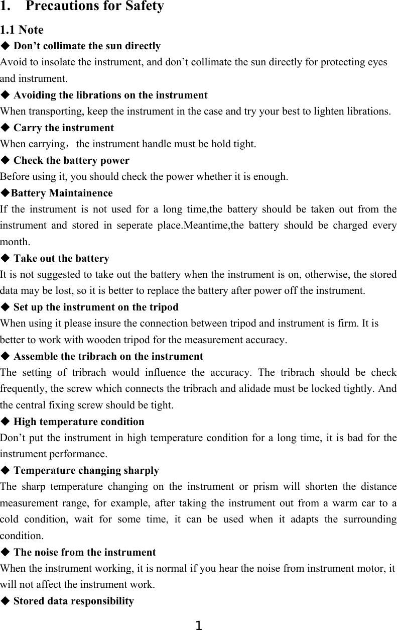
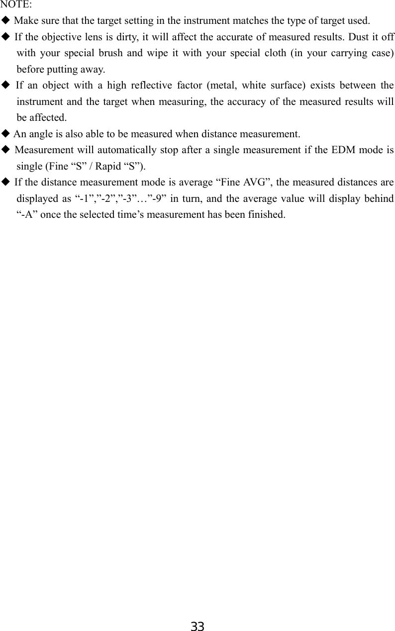
![29 Table 3-5 EDM setting Note: Options with the symbol “◆﹡” are the factory setting. ppm value could be calculated by inputted temperature and pressure, or input directly. ◆If the option of “ppm correct” is set as “Yes”, the temperature, pressure and ppm can not be inputted by hand. ◆ This operation is also available in stake out mode. You can press star{ }/F1[◆★EDM] key to enter EDM setting menu directly. Item Options 1.Mode Fine “r”﹡/ FineAVG 3 / Fine “s” / Rapid “s” / Tracking 2.Ref lector Prism﹡/ Sheet/ No prism 3.Pri. const -99~99 4.Temp. -30~60 (20℃℃﹡)/-22~140℉ 5.Pressure 500~1400hPa(1013hPa﹡); 375~1050mmHg(760mmHg﹡); 14.8~41.3 inchHg (29.9inchHg﹡) 500~1400mbar(1013mbar﹡); 7.2~20.3Psi(14.7Psi﹡) 6.ppm -499~499(0﹡), Press F1: [0PPM] to set temperature, pressure and ppm as factory setting.](https://usermanual.wiki/SUZHOU-FOIF/RTS102/User-Guide-2520405-Page-35.png)
![30 4. Angle Measurement 4.1 Measure a Horizontal Angle of Two Points 1. Sight the 1st target. Press F4: [0SET] twice to set the 1st target as 0°at P1 in the measure mode. Press [SHV1] or [SHV2] to change display status firstly if in distance mode. 2. Sight the 2nd target. The displayed value is the included angle between two points. 2nd target 1st target Meas PC 0.0 ppm 0 VD VA 85°55′50″ HA 0°00′00″ P1 DIST SHV1 SHV2 0 S E T Meas PC 0.0 ppm 0 VD VA 85°55′50″ HA 156°13′14″ P1 DIST SHV1 SHV2 0 S E T](https://usermanual.wiki/SUZHOU-FOIF/RTS102/User-Guide-2520405-Page-36.png)
![31 4.2 Set the Horizontal Angle to a Required Value 1. Take your instrument sight the 1st target. Press F4: [HSET] at P2 in the measure mode. 2. Select the first item 1.Azimuth, and input the required value in Azimuth filed, then press {ENT} to save the value. And it displays as the horizontal angle. The range and format of the input value: gon: 0~399.9999 degree: 0 ~359.5959 mil: 0~6399.990 3. Sight the 2nd target. The horizontal angle from the 2nd target to the value set as the horizontal angle is displayed. NOTE: Pressing [HOLD] performs the same function as above. The horizontal angle is in hold status when [HOLD] is flashing, press [HOLD] again to releasse the hold status. Set H Angle 1. Azimuth 2. Back sight Azimuth -399.9998 Tgt.H 0.000m PT# Observe point! OK Meas PC 0.0 ppm 0 VD VA 302.5432gon HA 0.0000gon P2 CORD MENU HOLD H S E T Meas PC 0 ppm 0 VD VA 302.5432gon HA 399.9998gon P2 CORD MENU HOLD H S E T](https://usermanual.wiki/SUZHOU-FOIF/RTS102/User-Guide-2520405-Page-37.png)
![32 5. Distance Measurement Please set the following items before distance measurement: ● Measurement condition ( See §3.8.1 Measure Condition Setting) ● EDM (See §3.8.6 EDM setting ) 【Procedure of distance measurement】 1. Aim at the target, press F3:[SHV2], the display mode of basic measurement will change to SD/HD/VD mode, and then press F1:[DIST] to start measure distance. 2. The symbol “*” moves continually when measuring distance. Distance measuring mode, prism const and ppm value are also presented. 3. Press F4: [STOP] to finish measurement. The “SD”,”HD”, and”VD” will display as shown left. 4. Press F3: [SHV2], SD/HD/VD and SD/VA/HA are displayed alternatively. Meas PC 0 ppm 0 SD 10.329m HD 7.009m VD 7.586m P1 DIST S H V 1 SHV2 0SET Meas PC 0 ppm 0 SD HD VD P1 DIST S H V 1 SHV2 0SET Meas PC 0 ppm 0 SD 10.329m HD 7.009m VD 7.586m P1 DIST S H V 1 SHV2 0SET Dist Fine ppm 0 -----※ STOP](https://usermanual.wiki/SUZHOU-FOIF/RTS102/User-Guide-2520405-Page-38.png)
![34 Occiped point Inst. Ht 6. Coordinate Measurement It is possible to find the 3D coordinates of a target by coordinate measurement. Please input the occupied coordinate, instrument height, target height, backsight coordinate (or azimuth angle) and azimuth before coordinate measurement. ○ N Target Ht Z Target point E 6.1 Input the Occupied Point Data 【Procedure of inputting occupied point data】 1. Measure the height of target and instrument with a tape, etc. 2. Press F1: [CORD] at P2 in the measurement mode. 3. Select “1. Occ. orientation”. 4. Select “1. Occ. coordinate” to input the occupied coordinates, instrument height and target height in corresponding field. Meas PC 0.0 ppm 0 SD VA HA P2 CORD MENU HOLD H S E T Coordinate 1. Occ. orientation 2. Measure 3. EDM 4. JOB select Coord 1. Occ. coordinate 2. Set H angle](https://usermanual.wiki/SUZHOU-FOIF/RTS102/User-Guide-2520405-Page-40.png)
![35 5. Press F3: [REC] to record the data in active occupied data list, see “§18.1 Record Occupied Data”. You could press F1: [READ] to read the existed data for occupied point from memory. You could also press F2: [RES] to enter Resection program to get the station point coordinate, see “§12. Resection”. Press F4: [OK] to confirm your setting. How to read the existed data: Known point data, coordinate data and instrument occupied data in the current JOB and coordinate search JOB can be read. Confirm that the JOB containing the coordinates you wanna read is already selected in coordinate search JOB, see “§22.2 Select a JOB ”. 1. Press F1: [READ] when inputting the coordinate. 2. The list of existed coordinate displays as shown left: Occ. : Occupied data saved in the current JOB or in the coordinate search JOB. Coord: Measured coordiante data saved in the current JOB or in the coordinate search JOB Pt# : Known point data saved in the current JOB or in the coordinate search JOB. ◆ [↑↓.P] : Press keys { }/ { } to move one by one. ◆ [↑↓.P]: Press keys { ▲ }/ {▼ } to turn the previous/next page. Press F1 to switch between [↑↓.P] status and [↑↓.P] status. ◆ [TOP]: Press it and the first point on the first page will display. ◆ [LAST]: Press it and the last point on the last page will display. ◆ [SRCH]: Press it to enter into “coordinate data search” mode. Input the required point number to search. 3. Select the required data and press the key {ENT}. The corresponding data will display. You could re-edit the data and it won’t affect the original coordinate data. 4. Press F4: [OK] to save the setting. PT# Inst.H 1.500m A N0: 0.000 E0: 0.000 Z0: 0.000 READ R E S R E C 0O K0 PT# Inst.H 1.500m A N0: 0.000 E0: 0.000 Z0: 0.000 READ R E S R E C 0O K0 Occ. Coord Coord PT# Coord ↑↓.P T O P LAST SRCH 15 56 20 50 45 PT# 5 Inst.H: 1.500m 1 N0: 100.000 E0: 100.000 Z0: 010.000 READ R E S R E C 0O K0](https://usermanual.wiki/SUZHOU-FOIF/RTS102/User-Guide-2520405-Page-41.png)
![36 NOTE: The point number that was read is displayed until the current JOB is changed or a new ◆point number is selected. If more than two points with the same point name exist in the current JOB, the ◆instrument finds the first recorded data only. 6.2 Azimuth Setting The azimuth of backsight could be inverse calculated by the coordinates of occupied and backsight. 1. Select “2. Set H angle”, see “§6.1 Input the occupied point data”. Then select “2. Backsight”. 2. Input the coordinate of backsight. You could also press F1: [READ] to select existed point data. If you input the same coordinates with the occupied point, a message “Same coordinates” will appear and disappear in 5sec,please re-input the data. 3. Press F4: [OK] to accept the inputted occupied and backsight coordinates, the calculated azimuth angle will display. 4. Aim at the backsight point, and then press F1:[MEAS] to check the backsight, or press F3: [REC] to record and set the station, then back to the previous mode. You could also press F4: [OK] to set the station, but the data will not be recorded. 0N Azimuth Angle Instrument StationESet H angle 1.Azimuth 2.Backsight Pt# P20 Tgt.H 0.000m 1 NBS: 20.000 EBS: 20.000 ZBS: 20.000 READ 0O K0 Azimuth 450000 Tgt.H 0.000m Pt# MEAS REC OK](https://usermanual.wiki/SUZHOU-FOIF/RTS102/User-Guide-2520405-Page-42.png)
![37 Note: You can select “◆1. Azimuth” to input the azimuth angle directly. After input the◆ coordinate of backsight, you can press F1:[MEAS] to check for backsight checking, HD between station and backsight, dHD and dVD between calculated backsight and measured backsight will be display. press F3: [REC] to record and set the station, then back to the previous mode.You could also press F4: [OK] to set the station,but the data will not be recorded. 6.3 3D Coordinate Measurement The target coordinate could be measured after the setting of occupied point and backsight azimuth. The formular used to calculate: N1=N0+S×sinZ×cosAz E1=E0+S×sinZ×sinAz Z1=Z0+S×cosZ+IH-TH Where: N0-E0-Z0: occupied point coordinates S:SD Z:Zenith angle Az:Azimuth angle IH:Instrument height TH:Target height SDIH Azimuth angle N E ZN0-E0-Z0 HDZenith angle Target (N-E-Z)Target heightAzimuth 45°00′00″ Tgt.H 1.000m Pt# HD 0.163m P1 REC OK II dHD 0.051m dVD 0.163m P2 REC OK](https://usermanual.wiki/SUZHOU-FOIF/RTS102/User-Guide-2520405-Page-43.png)
![38 【Procedure of 3D coordinates measurement】 1. Aim at the target point. 2. Select “2. Measure” to start. The coordinate value of the target is displayed. 3. Press F2: [TAGT] to re-input the occupied data if necessary, see “§6.1 Input the occupied point data”. You can press F4: [REC] to record the data. 4. Aim at the next target, press F2: [TAGT] to re-input the target height if necessary, and press F1: [MEAS] to continue. Follow this operation till all targets have been measured. 5. Press key {ESC} back to the coordinate mode. Coordinate 1. Occ. Orientation 2. Measure 3. EDM 4. JOB select N 1000.000 E 1000.000 Z 10.466 VA 132.3648gon HA 150.3536gon MEAS TAGT REC](https://usermanual.wiki/SUZHOU-FOIF/RTS102/User-Guide-2520405-Page-44.png)
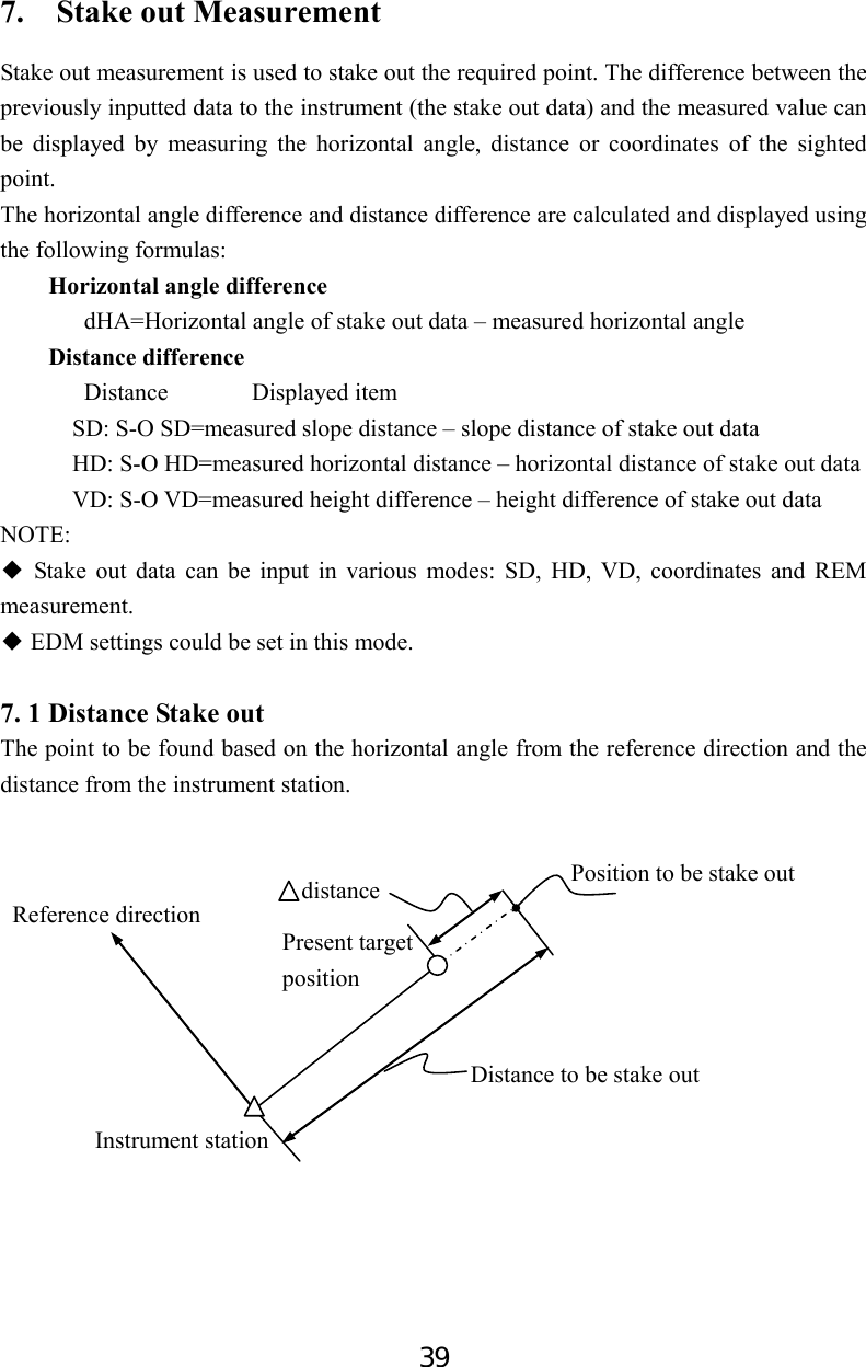
![40 【Procedure of distance stake out measurement】 1. Press F2: [MENU] at P2 in the measure mode. Select “2. Stake out”. 2. Select “1. Occ. Orientation”. Select “1. Occ. Orientation” ,Input the occupied orientation data, see “§6.1 Input the occupied point data ”. Then set the azimuth angle of the backsight point, see “§6.2 Azimuth setting”. 3. Select “2. S-O data”. 4. Select “2. Angle & Dist”. Press F2: [SHV] to shift between S-O SD, S-O HD, S-O VD. Input the following items: SD/HD/VD: distance from the instrument station to the position to be stake out; Ang.: included angle between the direction of the reference and the point to be stake out. See “§ 4.2 Set the Horizontal Angle to a Required value”. Press F4: [OK] to set the input values. S-O SD SD 5.000m Ang. 20.0000gon Tgt.H 0.000m SHV MOKS Menu P1 1.Coordinate 2.Stake out 3.Area 4.Offset 5.MLM S-O 1. Occ. Orientation 2. S-O data 3. EDM 4. JOB select S-O 1. Occ. Orientation 2. Set H angle S-O 1. Occ. Orientation 2. S-O data 3. EDM 4. JOB select Stake out 1.Height 2.Angle & Dist 3.Coord](https://usermanual.wiki/SUZHOU-FOIF/RTS102/User-Guide-2520405-Page-46.png)
![41 6. Horizontally rotate the instrument until “dHA” is near 0 and set the target on the sight line. Press F1: [MEAS] to start distance measurement. 7. The difference of measured and stake out value ”S-O dSD” is displayed. Move the prism forward and backward until “S-O dSD” is 0m. ←: Move the prism left →: Move the prism right ↓: Move the prism forward ↑: Move the prism backward Press F4: [OK] back to stake out mode. 7.2 Coordinates Stake out Measurement After setting coordinates for the point to be stake out, the instrument calculates the stake out HA and HD. By selecting the HA and then the HD stake out functions, the required coordinate location can be stake out. To get the Z coordinate, attach the target to a pole etc, with the same target height. 【Procedure of coordinate stake out measurement】 1. Press F2: [MENU] at P2 in the measure mode. Select “2. Stake out”. 2. Select “1. Occ. Orientation”. Input the occupied orientation data, see “§6.1 Input the occupied point data ”. Then set the azimuth angle of the backsight point, see “§6.2 Azimuth setting”. Point to be stake out Back sight station Instrumentstation DistancAngle 0EN S-O dSD↓ 0.000m dHA← 0.0000gon SD VD 149.3610gon HA 334.9916gon MEAS NEXT MOKS Stake out 1.Height 2.Angle & Dist 3.Coord Menu P1 1.Coordinate 2.Stake out 3.Area 4.Offset 5.MLM S-O 1. Occ. Orientation 2. S-O data 3. EDM 4. JOB select](https://usermanual.wiki/SUZHOU-FOIF/RTS102/User-Guide-2520405-Page-47.png)
![42 3. Press Esc, then Select “2. S-O data”, then select “3.Coord”. 4. Input the coordinates of the stake out point. Press F1: [READ] to read the existed coordinates as stake out coordinate. Press F4: [OK] to set the data. 5. Press F1: [MEAS] begin coordinate stake out measurement. Move the prism to find the point to be stake out. : Move the prism upward : Move the prism downward Press key {ESC} back to stake out mode. Pt# Tgt.H 1.500m 1 Np: 157.000 Ep: 0.178 Zp: 0.000 READ REC MOKS ↓ -147.328m → 0.000m 19.310m S-O dHD ↑ -147.328 dHA→ 146.7194gon P1 MEAS NEXT MRECS Stake out 1.Height 2.Angle & Dist 3.Coord VA 296.1184gon HA 249.0324gon P2 MEAS NEXT MRECS](https://usermanual.wiki/SUZHOU-FOIF/RTS102/User-Guide-2520405-Page-48.png)
![43 7.3 REM Stake out Measurement Perform this operation to find a point where a target cannot be directly installed, see “§11 REM”. 【Procedure of REM stake out measurement】 1. Set a target directly below or directly above the point to be found, then use a measuring tape etc. to measure the target height (height from the surveying point to the target). Press F2: [MENU] at P2 in the measure mode, then select “2. Stake out”. 2. Select “2. S-O data”, then select “1. Height”. 3. Input height from the surveying point to the position to be stake out. Then press F4: [OK] to set the data. 4. Press F2: [REM] to begin REM stake out measurement. Move telescope to find the point to be stake out. : Move the telescope near the zenith : Move the telescope near the nadir Press key {ESC} back to stake out mode. I SD 10.251m VA 79.6986gon HA 249.0404gon MEAS R E M NEXT S-O 1. Occ. Orientation 2. S-O data 3. EDM 4. JOB select Stake out 1.Height 2.Angle & Dist 3.Coord Ht. 2.000m Tgt.H 0.000m MOKS](https://usermanual.wiki/SUZHOU-FOIF/RTS102/User-Guide-2520405-Page-49.png)
![44 8. Area Calculate an area shaped with several points. The coordinate data of the points could be either measured or input by hand. Input: Output: Coordinates: P1 (N1, E1) Area:S P2 (N2, E2) P3 (N3, E3) … NOTE: ◆ The number of points: 3 ~ 30. ◆ Make sure these points must be measured or listed clockwise or anticlockwise, or mistake will result. 8.1 Area Calculation by Measured Data 【Procedure of area calculation】 1. Select F2: [MENU]/ 3. Area /2.Area. 2. Aim at the first point, and then press F4: [MEAS]. SP1P2P3P4P5E0NArea 1.Occ.Orientation 2.Area 01: 02: 03: 04: 05: READ MEAS](https://usermanual.wiki/SUZHOU-FOIF/RTS102/User-Guide-2520405-Page-50.png)
![45 3. Press F4: [MEAS] to re-measure distance or press F1: [OK], the measured data is set as“Pt-01”. 4. Repeat steps 2 and 3 till all points are measured one by one. Make sure measure them clockwise or anticlockwise. Press F2: [CALC] and the calculated area will display. 5. Press F4: [OK] back to menu mode. 8.2 Area Calculation by Reading Existed Coordinates 【Procedure of area calculation】 1. Select F2: [MENU]/ 3. Area /2.Area. . 2. Press F1: [READ] to display existed coordinates data list. N 10.000 I E 5.000 Z 53.493 VA 152.6296gon HA 62.1314gon 0OK0 MEAS 01:Pt_01 02:Pt_02 03:Pt_03 04:Pt_04 05: CALC MEAS Area Calculation Pt: 4 PArea m2 ha 0OK0 01: 02: 03: 04: 05: READ MEAS Menu P1 1.Coordinate 2.Stake out 3.Area 4.Offset 5.MLM](https://usermanual.wiki/SUZHOU-FOIF/RTS102/User-Guide-2520405-Page-51.png)
![46 3. Pt#: Known point data saved in the active JOB or in the coordinate search JOB. Occ./Coord: Coordinate data saved in the active JOB or in the coordinate search JOB. 4. Select the first point in the list and press key {ENT} to set. The selected point is set as “Pt-01”. 5. Repeat steps 2 and 4 till all points are selected. Make sure read the points clockwise or anticlockwise. 6. Press F2: [CALC], and the calculated area will display. Press F4: [OK] to escape. O1 Pt1 C1 Pt2 Pt3 Area Calculation Pt: 4 Area m2 ha 0OK0 01:O1 02:Pt1 03:C1 04:Pt2 05: READ CALC Occ. Pt# Coord Pt# Pt# ↑↓.P T O P LAST SRCH](https://usermanual.wiki/SUZHOU-FOIF/RTS102/User-Guide-2520405-Page-52.png)
![47 9. Offset Measurement Offset measurement are performed in order to find a point where a target cannot be installed directly or to find the distance and angle to a point which cannot be sighted. It is possible to find the distance and angle to a point you wish to measure (target point) by installing the target at a location (offset point) a little distance from the target point and measuring the distance and angle from the surveying point to the offset point. The target point could be found in the following three ways. 9.1 Single-distance Offset Measurement Finding a point by entering the horizontal distance from the target point to the offset point. When the offset point is positioned to the left or right of the target point, make sure the angle formed by lines connecting the offset point to the target point and to the instrument station is almost 90°. When the offset point is positioned in front of or behind the target point, installs the offset point on a line linking the instrument station with the target point. 【Procedure of single-distance offset measurement】 1. Set the offset point close to the target point and measure the distance between them, then set up a prism on the offset point. 2. Aim at the offset point and press F1: [MEAS] to Target pointOffset point(Target) Instrument stationMenu P1 1.Coordinate 2.Stake out 3.Area 4.Offset 5.MLM](https://usermanual.wiki/SUZHOU-FOIF/RTS102/User-Guide-2520405-Page-53.png)
![48 measure the distance at P1 in measure mode. 3. Select [MENU]/4. Offset, or press F3: [OFST] at P3 of basic measurement menu. 4. Select “1. Occ. orientation” to input the instrument occupied data, see “§6.1 Input the occupied point data”. 5. Select “2. Offset/Dist”. 6. User could press F1: [MEAS] to re-measure the offset point or press F4: [OK] to the next step. 7. Input distance and direction of offset point:. Dist: horizontal distance from the target point to ①the offset point. Direc: direction of the offset point.② ←: on the left of the target point →: on the right of the target point ↓: in front of the target point ↑: at back of the target point 8. Press F4: [OK] to calculate and display the distance and angle of the target point. 9. Press F1: [REC] to save; Press F2: [NEZ] to display NEZ coordinate; Press F3: [NO] back to step 6; Press F4: [YES] back to offset mode. I SD 10.186m VA 90.0000gon HA 64.5154gon MEAS MOKS Offset 1.Occ. Orientation 2.Offset/Dist 3.Offset/Angle 4.Offset/2Dist Offset 1.Occ. Orientation 2.Offset/Dist 3.Offset/Angle 4.Offset/2Dist Dist 10.000m Direc ↓ MOKS SD 13.511m VA 346.9636gon HA 249.0298gon REC NEZ M NOS YES](https://usermanual.wiki/SUZHOU-FOIF/RTS102/User-Guide-2520405-Page-54.png)
![49 9.2 Angle Offset Measurement Sighting the direction of the target point to find it from the included angle. Set offset points for the target point on the right or left sides of and as close as possible to the target point and measure the distance to the offset points and the horizontal angle of the target point. 【Procedure of angle offset measurement】 1. Set the offset points close to the target point (making sure the distance from the instrument station to the target point and distance to the offset point are same, the height of the offset points and the target point are the same), then use the offset points as the target. 2. Aim at the offset point and press F1: [MEAS] to measure the distance at P1 in measure mode. 3. Select [MENU] at P2 in measure mode, and then select “4. Offset”, or press F3: [OFST] at P3 directly. 4. Select “3. Offset/Angle” after inputting instrument occupied data, see “§6.1 Input the occupied point data”. 5. Accurately sight the direction of the target point and press F4: [OK], the distance and angle of the target point are displayed. 6. After finishing measurement: Press F1: [REC] to save; Press F2: [NEZ] to display NEZ coordinate; Press F3: [NO] back to step 6; Press F4: [YES] back to offset mode. Target pointInstrument stationOffset point (Target) Offset point(Target) Menu P1 1.Coordinate 2.Stake out 3.Area 4.Offset 5.MLM I SD 10.186m VA 90.0000gon HA 64.5154gon Aim at target? MEAS MOKS Offset 1.Occ. Orientation 2.Offset/Dist 3.Offset/Angle 4.Offset/2Dist I SD 13.511m VA 346.9636gon HA 249.0298gon Aim at target? REC NEZ M NOS YES](https://usermanual.wiki/SUZHOU-FOIF/RTS102/User-Guide-2520405-Page-55.png)
![50 9.3 Dual-Distance Offset Measurement By measuring the distance between the target point and the two offset points. Set two offset points (1st target and 2nd target) on a straight line from the target point, measure the 1st and 2nd target, then input the distance between the 2nd target and the target point to find the target point. 【Procedure of dual-distance offset measurement】 1. Set two offset points (1st target, 2nd target) on a straight line from the target point and use the offset points as target. 2. Select [MENU] at P2 in measure mode, and then select “4. Offset”, or press F3: [OFST] at P3 directly. 3. Select “4. Offset/2Dist” after inputting the instrument occupied data, see “§6.1 Input the occupied point data”. 4. Aim at the 1st target and press F1: [MEAS] and measured data will display. Press F4: [OK] to accept this value. Target pointInstrument stationOffset point(Target) Offset point (Target) Menu P1 1.Coordinate 2.Stake out 3.Area 4.Offset 5.MLM Observe 1st offset N 10.186 E 10.000 Z 10.000 P1 MEAS MOKS Offset 1.Occ. Orientation 2.Offset/Dist 3.Offset/Angle 4.Offset/2Dist](https://usermanual.wiki/SUZHOU-FOIF/RTS102/User-Guide-2520405-Page-56.png)
![51 5. Sight the 2nd target, press F1: [MEAS] and measured data will display, press F4: [OK] to accept this value. 6. Input the distance from 2nd point to the target point and press key {ENT}, the angle and distance of the target point are displayed. 7. Press F1: [REC] to save; Press F2: [NEZ] to display NEZ coordinate; Press F3: [NO] back to step 6; Press F4: [YES] back to offset mode. Observe 2nd offset N 10.186 E 10.000 Z 10.000 P1 MEAS MOKS Dist 123456789m Offset/2Dist SD 13.511m VA 346.9636gon HA 249.0298gon REC NEZ M NOS YES](https://usermanual.wiki/SUZHOU-FOIF/RTS102/User-Guide-2520405-Page-57.png)
![52 10. MLM MLM is used to directly measure slope distance, horizontal distance and the height difference from one base point to other points without moving the instrument. NOTE: ◆ The last measured data could be set as the base point for the next starting operation. ◆ The height difference between one point and the base point could be displayed as grade mode. 10.1 Measuring Distance between Two or More Points 【Procedure of measuring】 1. Press F2: [MENU] at P2 in the measure mode. Select “5. MLM”. 2. Aim at the start point P1, then press F4: [MEAS] and the measured data will display. 3. Aim at the target point P2 and press F1: [MLM] to begin measure, SD, HD, VD will display. H2 H1 S2S1 %1%2V2 V1 Target (P2)Start point (P1) Target (P3)Occupied point I SD 33.421ft HD 155.6594gon VD 355.9246gon MLM MOVE MEAS Menu P1 1.Coordinate 2.Stakeout 3.Area 4.Offset 5.MLM](https://usermanual.wiki/SUZHOU-FOIF/RTS102/User-Guide-2520405-Page-58.png)
![53 4. Aim at the next point P3 and press F1: [MLM] to begin measure. Repeat this operation to measure other target points. 5. Press F2: [MOVE], the last target measured becomes the new starting position to perform MLM of next target. Press F4: [MEAS] to re-measure the starting position. 6. Press key {ESC} back to menu mode. Note: Once “S/%” is displayed, the distance between two points is displayed as the gradient◆ 10.2 Change the Starting Point The previous measured data could be set as the base point for the next operation. 【Procedure of changing the starting point】 1. Measure the start point P1 and the first target P2 following above steps 1, 2 and 3. 2. After measuring the two points, press F2: [MOVE], and press F4: [YES] to set the last measured point as new starting point, or press F3: [NO] to give up. H2H1S2S1 %1%2V2 V1 Start point (P1) Point (P2) Point (P3) Move base point? SD -0.001m VA 368.3854gon HA 243.4068gon MNOS YES I S/% % SD HD MLM MOVE MEAS](https://usermanual.wiki/SUZHOU-FOIF/RTS102/User-Guide-2520405-Page-59.png)
![54 11. REM REM is a function used to measure the coordinate and height to a point where a target cannot be directly installed such as power lines, overhead cables or bridges, etc. Here is the equation used to calculate the data presented in above figure: Ht=H1+Scosα1tgα2-Ssinα1 【Procedure of REM】 1. Set a target directly under or directly over the object and measure the target height with a tape measure etc. 2. Press F2: [MENU] on P2 of the basic measurement mode, then press Func key to turn to page 2, then select “1.REM” on P2 to enter into REM status. 3. Reference point measurement. Aim at the prism accurately, and press F4: [MEAS] to measure distance. Press F4: [STOP] and the measured data are displayed. Press F4: [MEAS] to re-measure. 4. Aim at the target accurately and press F2: [REM]. The height from ground to the target is displayed in “Ht”. Press F4: [MEAS] to repeat and press key {ESC} back to menu mode. α1 Ht H2 H1 B’ STarget point B α2 I SD HD VD REM MEAS Menu P2 1.REM 2. Resection 3. Point Projection 4. Line stake out 5. Traverse I SD HD VD REM MEAS](https://usermanual.wiki/SUZHOU-FOIF/RTS102/User-Guide-2520405-Page-60.png)
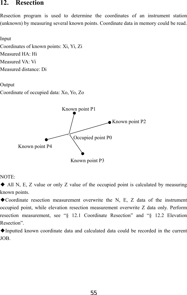
![56 12.1 Coordinate Resection Between 2 and 5 known points can be measured by distance measurement and angle measurement. 【Procedure of coordinate resection】 1. Select [MENU] at P2 of basic measurement mode, then press Func key to turn to page 2, and then select “2. Resection”, or select [RES] at P3 directly. 2. Select “1.NEZ” and input known point data. After inputting the data of the first known point, press F3: [NEXT] to input the second point data. 3. After all known points data have been set, press F4: [MEAS]. Press F1: [READ] to read existed coordinate data. 4. Sight the first known point and press F1: [DIST] to begin measurement. If known points number is more than two, F2: [ANG] will display, you can confirm the known point by angle measurement. 5. Press F4: [YES] to use the measured data of the first known point. Press F3: [NO] to re-measure this point. You can also input target height here. Resection No.1Pt I SD 10.188m VA 189.9284gon HA 47.2432gon Tgt.H 000000m TNOT YES Resection 1.NEZ 2.Elevation Resection No.1PT N E Z Pt# DIST ANG Menu P2 1.REM 2. Resection 3. Point Projection 4. Line stake out 5. Traverse Pt# Tgt.H m 1 Np: Ep: Zp: READ R E C NEXT MEAS](https://usermanual.wiki/SUZHOU-FOIF/RTS102/User-Guide-2520405-Page-62.png)
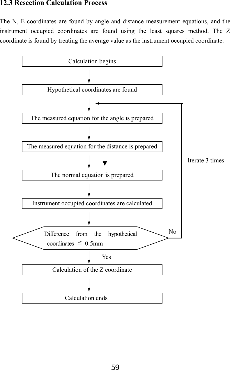
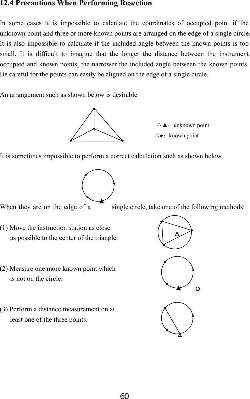
![57 6. Repeat procedures 4 and 5 of other points. When the minimum quantity of measured data required for the calculation is present, [CALC] will be displayed. Press F1: [CALC] to calculate. Instrument occupied coordinate and standard deviation are displayed. Press F3: [NO] to re-measure the point. 7. Press F1: [NEXT] to add other known points. Press F2:[DISP] to view the tolerance of measured known points Press F3: [REC] to record the calculated result. Press F4: [OK] to finish coordinate resection. The instrument occupied coordinate setting is finished. 8. In this <Set Azimuth> screen, aim the first point then press F4: [YES] to set the first known point as backsight point and azimuth, press F3: [NO] to back to measure mode. 12.2 Elevation Resection Only Z (elevation) of an instrument station is dertermined by this measurement. Between 1 and 5 known points can be measured by distance measurement only. 【Procedure of elevation resection】 1. Press F2: [MENU] on P2 of the basic measurement mode, then press Func key to turn to page 2, and then select “7. Resection”, or press F4: [RES] at P3 directly. 2. Select “2. Elevation” and input the known point. Resection Set Azimuth TNOT YES N E Z dN dE NEXT DISP REC TOKT Menu P2 1.REM 2. Resection 3. Point Projection 4. Line stake out 5. Traverse Resection No.2Pt I SD 10.188m VA 189.9284gon HA 47.2432gon Tgt.H 000000m CALC TNOT YES Resection 1.NEZ 2.Elevation](https://usermanual.wiki/SUZHOU-FOIF/RTS102/User-Guide-2520405-Page-63.png)
![58 3. After setting the elevation for the first known point, press F3: [NEXT] to set the second point data. 4. After all known points data have been set, press F4: [MEAS]. Press F1: [READ] to read existed coordinate data. 5. Sight the first known point and press F1: [DIST] to begin measurement. The measured data are displayed. 6. Press F4: [YES] to use the measured data of the first known point data. Press F3: [NO] to re-measure the point. You can also input target height here. After finishing two measurements, [CALC] will be displayed. 6. Press F1: [CALC] to calculate. Instrument occupied elevation and standard deviation are displayed. 7. Press F1: [NEXT] to add other known points. Press F3: [REC] to record the calculated result. Press F4: [OK] to finish elevation resection. Only Z (elevation) of the instrument occupied coordinate is set. N and E values would not be overwritten. No. 1Pt# 1 Pt# Tgt.H m Z READ R E C NEXT MEAS Resection No.1PT Z Pt# DIST Resection No.1Pt I SD 10.188m VA 189.9284gon HA 47.2432gon Tgt.H 000000m CALC TNOT YES Occ.Coord Z dZ NEXT REC TOKT](https://usermanual.wiki/SUZHOU-FOIF/RTS102/User-Guide-2520405-Page-64.png)
![61 13. Point Projection Point projection is used for projecting a point to an established baseline. The point to project can be either measured or input. Displays the distances from the first point and point to project to the position at which a line extending from point to project intersects the baseline at right angles. Length: Distance along the baseline from 1st point to 2nd point (X direction). Offset: Distance from point to project to the position at which a line extending from point of project intersects the baseline at right angles (Y direction). 13.1 Define Baseline 【Procedure of defining baseline】 1. Press F2: [MENU] at P2 of basic measurement mode. 2. Turn to P2, select “3. Point projection”. Menu P2 1.REM 2.Resection 3.Point projection 4.Line stake out 5.Traverse X direction Length 1st Pt 2nd Pt Offset BaselinePoint to projectY direction](https://usermanual.wiki/SUZHOU-FOIF/RTS102/User-Guide-2520405-Page-67.png)
![62 3. Input the instrument occupied data, see “§6.1 Input the occupied point data”. 4. Select “2. Define baseline”. 5. Input the first point data, or press F1: [READ] to use existed coordinates data, or press F3:[MEAS] to measure the point. 6. Press F4: [OK] to input the second point data. 7. Press F4: [OK] to finish defining baseline. The grade of the baseline will display. 8. Press F2: [1:**] or F3: [%] to change the grade display mode. NOTE: Defined baseline could be used in both stake out line measurement and point ◆projection. Define 1st Pt. Pt#: 1 Np: Ep: Zp: READ R E C M E A S OK Point projection 1.Occ. Orientation 2.Define baseline 3.Point projection Point projection 1.Occ. Orientation 2.Define baseline 3.Point projection Define 2st Pt. Pt#: 1 Np: Ep: Zp: READ R E C M E A S OK Azimuth 300gon HD 10.412m Grade 1:150 1:** 0 %0 HOKD 0.000 0.000 0.000 0.000 0.000 0.000](https://usermanual.wiki/SUZHOU-FOIF/RTS102/User-Guide-2520405-Page-68.png)
![63 13.2 Point Projection The baseline must be defined before performing point projection. 【Procedure of point projection】 1. Select “3. Point projection” after finishing defining baseline. 2. Input the point coordinate. Press F2: [MEAS] to measure the point to project. When recording the data as a known point, press key {Func}, and press F2: [REC] on P2. Record method, see “§ 23.1 Input Known Point Coordinate by Keys”. 3. Press F4: [OK] to calculate Length, Offset and dVD will display. Length: Distance along the baseline from 1st point to 2nd point (X direction). Offset: Distance from point to project to the position at which a line extending from point of project intersects the baseline at right angles (Y direction) dVD: Elevation between the baseline and the projected point. Press F1: [NEZ] to display switching between coordinate and distance data. Press F2: [REC] to record the coordinate as a known data. Press F4: [S-O] to switch to stake out measurement of the projected point. See “6 Stake out measurement”. Press key {ESC} to continue point projection of a new point. Length Offset dVD NEZ REC S-O Point projection 1.Occ. Orientation 2.Define baseline 3.Point projection Pt#: Np: A Ep: Zp: P1 READ MEAS HOKD 1385.260m -203.107m 2.212m](https://usermanual.wiki/SUZHOU-FOIF/RTS102/User-Guide-2520405-Page-69.png)
![64 14. Stake out Line Stake out line is used for stake out a required point at a designed distance from the base line and for finding the distance from the baseline to a measured point. 14. 1 Define Baseline 【Procedure of defining baseline】 To perform stake out line, please define a baseline first. The baseline can be defined by inputting coordinates of the two points. 1. Press F2: [MENU] on P2 of the basic measurement mode. 2. Turn to P2, select “4. Stake out line”. 3. Input the instrument occupied data, see “§6.1 Input the occupied point data”. 4. Select “2. Define baseline”, following operations see “§13.1 Define baseline” procedures 5, 6 and 7. Menu P2 1.REM 2.Resection 3.Point projection 4.Line stake out 5.Traverse Stake out line 1.Occ. Orientation 2.Define baseline 3.Stake out line OffsetLengthFillGrade2ndPt1st PtBaselineAzimuthZ N E Cut](https://usermanual.wiki/SUZHOU-FOIF/RTS102/User-Guide-2520405-Page-70.png)
![65 14. 2 Stake Out Line-Point This measurement can be used to find the required point coordinates by inputting the length and offset based on baseline. Length: Distance along the baseline from 1st point to the position at which a line extending from the required point intersects the baseline at right angles (X direction) Offset: Distance from the required point to the position at which a line extending from the required point intersects the baseline at right angles (Y direction). 【Procedure of stake out】 1. Select “3. Stake out line” after defining a baseline. 2. Select “1. Point” 3. Input values of length and offset, then press F4: [OK], the coordinate of the required point is calculated and displayed. Stake out line 1.Occ. Orientation 2.Define baseline 3.Stake out line Stake out line 1.Point 2.Line Stake out line Length Offset HOKD Required pointLength X direction 1st Pt 2nd Pt Offset BaselineY direction](https://usermanual.wiki/SUZHOU-FOIF/RTS102/User-Guide-2520405-Page-71.png)
![66 4. Press F2: [REC] to record the value as a known point, see “§20.1 Input Known Point Coordinate by Keys”. Press F4: [S-O] to stake out the required point, see “§7. Stake out Measurement”. Press key {ESC} to continue. 14.3 Stake out Line/Line Stake out line-line tells how far horizontally the measured point is from the baseline and how far vertically the measured point is from the connected line. Make sure to define a baseline before this operation. Offline: A positive value indicates the point is on the right of the baseline and a negative value indicates it is on the left. Cut: indicates that the point is below the baseline. Fill: indicates that the point is above the baseline. Length: distance along the baseline from 1st point to the measured point. Stake out line Np: Ep: Zp: REC S-O Offset (horizontal direction)LengthMeasured pointOffline (-)1st Pt Cut2nd Pt Measured point0.000 0.000 0.000 Profile view](https://usermanual.wiki/SUZHOU-FOIF/RTS102/User-Guide-2520405-Page-72.png)
![67 【Procedure of stake out line/line】 1. Select “3. Stake out line” after defining a baseline. 2. Select “2.Line”. 3. Input offset value: the horizontal move distance of baseline, right side indicates positive value and left side indicates negative value. Go to step 4 without inputting. 4. Aim at the target and press F4: [MEAS] to measure. The measured results are displayed. 5. Press F3: [NO] to re-measure the target. Press F4: [YES] to use the measured values. The difference between the measured data and the baseline displays: Ofline: A positive value indicates the point is on the right of the baseline and a negative value indicates it is on the left. “Cut” indicates that the point is below the baseline. “Fill” indicates that the point is above the baseline. Length: Distance along the baseline from the first point to the measured point. 6. Aim at the next target and press F4: [MEAS] to continue the measurement. Stake out line 1.Occ. Orientation 2.Define baseline 3.Stake out line Stake out line 1.Point 2.Line Stake out line Offset MEAS Stake out line I SD 33.417ft VA 300.9994gon HA 44.6568gon Tgt.H HNOT YES Stake out line Ofline -0.995m Fill 14.401m Length 3.993m REC MEAS](https://usermanual.wiki/SUZHOU-FOIF/RTS102/User-Guide-2520405-Page-73.png)
![68 15. Traverse Surveying Measure the coordinate of foresight point and save it in the list, this point would be taken as the occupied point after transferring to point 2, and the previous occupied point will be taken as the backsight point, the azimuth angle will be calculated and set. 15.1 Save Coordinate Here is the operation of how to measure the foresight point and save it in the list. 【Procedure of saving coordinate】 1. Press F2: [MENU] on P2 of the basic measurement mode. 2. Turn to P2, select “3.Traverse”. 3. Press “1.Save coord”. (0,0,0) N EOccupied point P0Azimuth Known point A P1 P2 P3 Meas PC 0.0 ppm 0 SD VA HA P2 CORD MENU HOLD H S E T Menu P2 1.REM 2.Resection 3.Point projection 4.Line stake out 5.Traverse Traverse 1.Save coord 2.Read coord](https://usermanual.wiki/SUZHOU-FOIF/RTS102/User-Guide-2520405-Page-74.png)
![69 3. Aim at the target point and then press F1: [DIST]. You can press F4: [I.HT] to re-input instrument height or target height here. 4. Press F4: [SET] to save the data, or press F3: [REC] to record it in the list. 5. Press F3: [NO] back to the previous mode and press F4: [YES] to set the data. 15.2 Read Coordinate Set the measured foresight point in the saved coordinates list as the occupied point, and the previous occupied point becomes the back point. 1. Move the instrument to the measured forsight point. 2. Select “2. Read coord”. 3. First aim the previous occupied point, then press F4: [YES] to set the previous foresight point coordinate as the occupied point coordinate or press F3: [NO] to give up. I VD 29.183ft VA 315.3212gon HA 64.5876gon DIST I.HT I VD 19.682ft VA 159.9150gon HA 68.0594gon MEAS REC SET N 5.000 E 5.000 Z 29.877 > Set? 0NO0 YES Traverse 1.Save coord 2.Read coord HA -0.0002gon > Set? 0NO0 YES](https://usermanual.wiki/SUZHOU-FOIF/RTS102/User-Guide-2520405-Page-75.png)
![70 16. Inverse The distance and azimuth from a start point to an end point could be calculated according to input their coordinates. Input: Output: Coordinate of start point: N0,E0,Z0 Distance: D Coordinate of end point : N1,E1,Z1 Azimuth: Az 【Procedure of Inversing】 1. Press F2: [MENU] on P2 of the basic measurement mode. 2. Turn to P3, select “1.Inverse”. 3. Input coordinates of the start point, and press F3: [REC] to record the data in the list if necessary. You could press F1: [READ] to read the existed data. Press F4: [OK] to set. 4. Input coordinates of the end point. See the previous step. 5. The inversed value will display. Press F3: [NEXT] to continue, press F4: [OK] back to menu mode. Menu P3 1.Inverse 2.Polarize 3.Repeat Measure 4.Arc staking out 5.Road Calculation Start point Pt# A N 1000.000 E 1000.000 Z 39.383 READ REC 0OK0 End point Pt# A N 1000.000 E 1000.000 Z 39.383 READ REC 0OK0 Azimuth -0.0002gon HD 0.000ft VD -29.383ft NEXT 0OK0](https://usermanual.wiki/SUZHOU-FOIF/RTS102/User-Guide-2520405-Page-76.png)
![71 17. Polar Coordinates Calculation The coordinates of the end point could be calculated according to input azimuth, distance and the NEZ coordinates of start point. Input: Coordinate of start point: N0,E0,Z0 Azimuth: Az Distance: Dist Output: Coordinate of end point:N1,E1,Z1 【Procedure of Polarize】 1. Press F2: [MENU] on P2 of the basic measurement mode. 2. Turn to P3, select “2.Polarize”. 3. Input the data in corresponding items. You could press F1: [READ] to read the existed coordinate data for start point. Press F4: [OK] to enter. 4. The calculated data displays. Press F3: [REC] to record it in the list, and press F1: [OK] back to menu mode. NStart pointEnd point DAzMenu P3 1.Inverse 2.Polarize 3.Repeat Measure 4.Arc staking out 5.Road Calculation P1 Pt# A N 1000.000 E 1000.000 Z 39.383 READ 0OK0 N 1000.000 E 1000.000 Z 0.000 0OK0 REC](https://usermanual.wiki/SUZHOU-FOIF/RTS102/User-Guide-2520405-Page-77.png)
![72 18. Repetition Angle Measurement Repetition angle measurement can be done by horizontal angle right measurement mode. 1. Press F2: [MENU] on P2 of the basic measurement mode. 2. Turn to P3, select 3.Repeat Measure. 3. Press the F3:[Yes] key. 4. Collimate the target A and press the F1[0SET] key. 5. Press the F3:[Yes] key. 6. Collimate the target B using the horizontal clamp and tangent screw. Press the F4:[HOLD] key. 7.Recollimate the target A using the horizontal clamp and tangent screw, and press the F3:[FREE] key. 8. Recollimate the target B using the horizontal clamp and tangent screw, press the F4:[HOLD] key. 9. Repeat 7 to 8 to measure the desired number of repetition. Menu P3 1.Inverse 2.Polarize 3.Repeat Measure 4.Arc staking out 5.Road Calculation Angle ReMeasure >OK? ---- ---- YES N O Angle Remeasure [0] Ht: 0°00′00″ Hm: 0SET MEAS FREE H O L D Angle Remeasure [1] Ht: 45°10′00″ Hm: 45°10′00″ 0SET MEAS FREE H O L D Angle Remeasure [1] Ht: 45°10′00″ Hm: 45°10′00″ 0SET MEAS FREE H O L D Angle Remeasure [2] Ht: 45°10′00″ Hm: 45°10′00″ 0SET MEAS FREE H O L D](https://usermanual.wiki/SUZHOU-FOIF/RTS102/User-Guide-2520405-Page-78.png)
![73 10. Press F2: [Meas] or [ESC] key to return to the normal mode. 11. Press the F3:[YES] key. NOTE: ● Horizontal angle can be accumulated up to (3600°00'00" – minimum reading) (horizontal angle right). In case of 5 second reading, horizontal angle can be accumulated up to +3599°59'55". ● Error will be displayed when the results differ from first measurement by more than ±30". Angle Remeasure [4] Ht: 45°10′00″ Hm: 45°10′00″ 0SET MEAS FREE H O L D Angle ReMeasure Exit >OK? ---- ---- YES N O](https://usermanual.wiki/SUZHOU-FOIF/RTS102/User-Guide-2520405-Page-79.png)
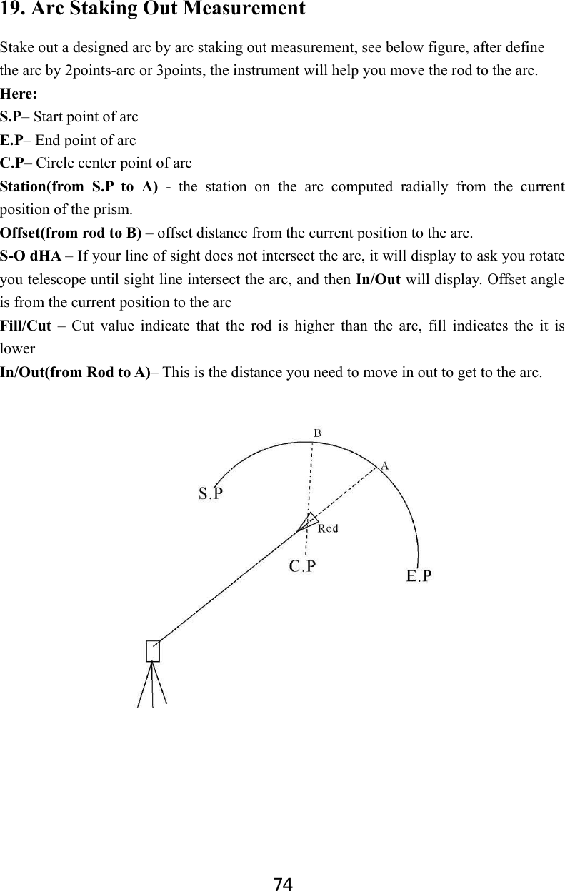
![75 19.1 Two Point Arc Staking Out 1. Press F2: [MENU] on P2 of the basic measurement mode, select 4.Arc Staking out to enter arc staking out menu, select 1.Occ.Orientation to set the station. And then select 2. 2pt+radius arc to start 2-point arc staking out measurement. 2. Input the coordinate of arc start point. Press F1[READ] to read the existed coordinate as stake out coordinate Press F4:[OK] to set the data. 3. Input the coordinate of arc end point. Press F1[READ] to read the existed coordinate as stake out coordinate Press F4:[OK] to set the data. 4. Input the radius of arc, press F4:[OK] to set the data. 5. Press F1:[MEAS] to measure current rod, the staking date will display. Length - the station on the arc computed radially from the current position of the prism OfLine– offset distance from the current position to the arc dHA – offset angle from the current position to the arc – Cut value indicate that the rod is higher than the arc, fill indicates the it is lower ↑– This is the distance you need to move in out to get to the arc. Arc Stakeout 1.Occ.Orientation 2.2pt+radius arc 3.Three point arc Define/Start PT Pt# A Np: 11.829 Ep: 0.000 Zp: 1.846 READ R E C MEAS OK Arc define/Rad Input Rad 100.000 OK ↑ 21.172m 9.603m dHA ← 12°27’49” P1 Length 8.304m OfLine 4.928m MEAS OK Define/End PT Pt# A Np: 11.829 Ep: 0.000 Zp: 1.846 READ R E C MEAS OK](https://usermanual.wiki/SUZHOU-FOIF/RTS102/User-Guide-2520405-Page-81.png)
![76 6. According the S-O dHA angle to move the rod until the telescope sight intersect the arc. 7. Repeat moving and measuring the rod until all the stake data are accepted. Press F4: [ESC] to escape this program. 19.2 Three Point Arc Staking Out 1. Press F2: [MENU] on P2 of the basic measurement mode, select 4.Arc Staking out to enter arc staking out menu, select 1.Occ.Orientation to set the station. And then select 3.Three point arc to start three-point arc staking out measurement. 2. Input the coordinate of arc start point. Press F1[READ] to read the existed coordinate as stake out coordinate Press F4:[OK] to set the data. 3. Input the coordinate of arc end point. Press F1[READ] to read the existed coordinate as stake out coordinate Press F4:[OK] to set the data. ↑ 0.003m 0.006m dHA ← 0°00’05” P1 Length 1.109m OfLine 0.003m MEAS OK Arc Stakeout 1.Occ.Orientation 2.2pt+radius arc 3.Three point arc Define/Start PT Pt# A Np: 11.829 Ep: 0.000 Zp: 1.846 READ R E C MEAS OK Define/End PT Pt# A Np: 11.829 Ep: 0.000 Zp: 1.846 READ R E C MEAS OK](https://usermanual.wiki/SUZHOU-FOIF/RTS102/User-Guide-2520405-Page-82.png)
![77 4. Input the coordinate of arc middle point. Press F1[READ] to read the existed coordinate as stake out coordinate Press F4:[OK] to set the data. 5. Press F1:[MEAS] to measure current rod, the staking date will display. Length - the station on the arc computed radially from the current position of the prism. OfLine – offset distance from the current position to the arc. dHA – offset angle from the current position to the arc – Cut value indicate that the rod is higher than the arc, fill indicates the it is lower ↑(from Rod to A)– This is the distance you need to move in out to get to the arc. 6. According the S-O dHA angle to move the rod until the telescope sight intersect the arc. 7. Repeat moving and measuring the rod until all the stake data are accepted. Press F4: [ESC] to escape this program. Arc define/Rad Input Rad 100.000 OK ↑ 21.172m 9.603m dHA ← 12°27’49” P1 Length 8.304m OfLine 4.928m MEAS OK Arc define/Mid PT Pt# A Np: 11.829 Ep: 0.000 Zp: 1.846 READ R E C MEAS OK](https://usermanual.wiki/SUZHOU-FOIF/RTS102/User-Guide-2520405-Page-83.png)
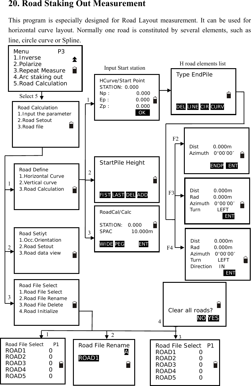
![79 20.1 Input the Start Station 1. Press F2: [MENU] on P2 of the basic measurement mode, on the page 3 select 5.Road Calculation enter road menu. 2. Select 1.Input the parameter to enter road design menu. And then select 1.Horizontal Curve, start point entering menu will display. 3. Enter the start point station and coordinate, press F4:[OK] key. Road horizontal elements editing menu will display. 20.2 Input Road Horizontal Elements Three types elements can be input, including line, curve and spiral. 20.2.1 Input Line Element 1. Make sure the instrument is in horizontal elements editing menu, press F2 to display line element inputting menu. Input the line length and azimuth in the Dist and Azimuth filed. Press F4:[ENT] key to confirm. Road Calculation 1.Input the parameter 2.Road Setout 3.Road file Road Define 1.Horizontal Curve 2.Vertical curve 3.Road Calculation HCurve/Start Point STATION: 0.000 Np : 0.000 Ep : 0.000 Zp : 0.000 0OK0 Type EndPile DELv LINEv CIR CURV Dist 100m Azimuth 0°00′00″ ENDP ENT](https://usermanual.wiki/SUZHOU-FOIF/RTS102/User-Guide-2520405-Page-85.png)
![80 NOTE: You can press F3:[ENDP] to enter the end point inputting menu. Input the end point coordinate directly, or press F1:[READ] to recall from memory. Press F3:[LINE] to back to the LENGTH menu Press F4:[ENT] to confirm, you will see the line element in the list menu. Here EndPile means the end station of this element. 20.2.2 Input Circle Element 1. Make sure the instrument is in horizontal elements editing menu, press F3 to display curve element inputting menu. Input the curve parameters, including length[Dist], radius[Rad], azimuth[Azimuth] and turn [Turn]. 2. Press F4:[ENT] key to confirm, back to the horizontal elements menu. Here EndPile means the end station of this element. NOTE: 1. Normally the azimuth will calculate and display following previous element. 2. When you set the turn, move the cursor to [Turn] item, press ◄ or ► key to shift between Left and Right. Line Input/END POINT Pt# A N 100m E 0.000m Z 0.000m READ LEN ENT Type EndPile Line 100.000 DEL LINE CIR CURV Dist 100.000m Rad 100.000m Azimut 0°00′00″ Turn: RIGHT ENT Type EndPile Line 100.000 Circle 200.000 DEL LINE CIR CURV](https://usermanual.wiki/SUZHOU-FOIF/RTS102/User-Guide-2520405-Page-86.png)
![81 20.2.3 Input Spiral Element 1. Make sure the instrument is in horizontal elements editing menu, press F4 to display spiral element inputting menu. Input the curve parameters, including length[Dist], radius[Rad], azimuth[Azimuth], turn [Turn] and direction[Direction]. 2. Press F4:[ENT] key to confirm, back to the horizontal elements menu. Here EndPile means the end station of this element. NOTE: 1. Normally the azimuth will calculate and display following previous element. 2. When you set the turn or direction, move the cursor to [Turn] or [Direction]item, press ◄ or ► key to shift the options. 3. If you set the Direction is IN, here the inputted Rad is End radius of spiral, its start radius is default as ∞; if you set the direction is OUT, here the inputted is start radius of spiral, its end radius is default as ∞. 20.2.4 Road Horizontal Element Editing In the horizontal element editing menu, the inputted element can be edited. ● Delete horizontal element 1. Move ▲ or ▼ key, the cursor will move to different element. 2. Press F1:[DEL] to delete the selected element, the two elements adjacent with deleted one will connect automatically. Dist 100.000m Rad 100.000m Azimuth 57°17′44″ Turn RIGHT Direction IN ENT Type EndPile Line 100.000 Circle 200.000 Spiral 300.000 DEL LINE CIR CURV Type EndPile Line 100.000 Circle 200.000 Spiral 300.000 Circle 400.000 DEL LINE CIR CURV Type EndPile Line 100.000 Circle 200.000 Spiral 300.000 Circle 400.000 DEL LINE CIR CURV](https://usermanual.wiki/SUZHOU-FOIF/RTS102/User-Guide-2520405-Page-87.png)
![82 ● Edit horizontal element 1. Move ▲ or ▼ key, the cursor will move to different element. 2. Press ENT key to edit the selected element. 3. Press F4:[ENT] key to confirm, other elements following the edited one will upgrade automatically. 4. After all the horizontal elements are confirmed, press [ESC] key back to previous menu. Type EndPile Line 100.000 Spiral 200.000 Circle 300.000 Spiral 400.000 DEL LINE CIR CURV Type EndPile Line 100.000 Spiral 200.000 Circle 300.000 Spiral 400.000 DEL LINE CIR CURV Dist 200.000m Rad 100.000m Azimuth 0°00′00″ Turn RIGHT Direction IN ENT Type EndPile Line 100.000 Spiral 300.000 Circle 400.000 Spiral 500.000 DEL LINE CIR CURV Road Define 1.Horizontal Curve 2.Vertical curve 3.Road Calculation](https://usermanual.wiki/SUZHOU-FOIF/RTS102/User-Guide-2520405-Page-88.png)
![83 20.3 Input Road Vertical Elements Road vertical elements is confirmed by some intersection points, you should input same parameters for the intersection points, including station, height, and length from this intersection point to next intersection point. 20.3.1 Input Vertical Road Element. 1. Make sure the instrument is in Road Define menu, select 2.Vertical Curve to vertical elements editing menu. Here: Press F1:[FIST] key, the cursor will move to the first element. Press F2:[LAST] key, the cursor will move to the last element. Press F3:[Del] key to delete the selected element. Press F4:[ADD] key to add a new vertical element. 2. Press F4 to display Vertical road element inputting menu. Input the parameter for vertical element. Press F4:[ENT] key to confirm. Road Define 1.Horizontal Curve 2.Vertical curve 3.Road Calculation StartPile Height FIST LAST DEL ADD VCurve/Element 1 STATION: 0.000 Ht. 600.000m Length 200m ENT](https://usermanual.wiki/SUZHOU-FOIF/RTS102/User-Guide-2520405-Page-89.png)
![84 3. You will see the just inputted element in the vertical element editing menu. 4. Press F4:[ADD] to input next one. Here the STATION is displayed automatically, it comes from the previous element’s length. Press F4: key to confirm. 5. Repeat step 4 to input all the vertical elements for the road. 20.3.2 Edit Vertical Road Element In the horizontal element editing menu, the inputted element can be edited. ● Delete vertical element 1. Move F1:[FIST], F2:[LAST], ▲ or ▼ key, the cursor will move to different element. 2. Press F3:[DEL] to delete the selected element, the two elements adjacent with deleted one will connect automatically. For example, after delete the second element, the vertical road curve figure is shown below: VCurve/Element STATION 200.000 Ht. 625.000 Lengh 250 ENT StartPile Height 0.000 600.000 FIST LAST DEL ADD StartPile Height 0.000 600.000 200.000 625.000 400.000 570.000 550.000 700.000 FIST LAST DEL ADD StartPile Height 0.000 600.000 200.000 625.000 400.000 570.000 500.000 685.000 FIST LAST DEL ADD StartPile Height 0.000 600.000 200.000 570.000 300.000 685.000 FIST LAST DEL ADD](https://usermanual.wiki/SUZHOU-FOIF/RTS102/User-Guide-2520405-Page-90.png)
![85 ● Edit horizontal element 1. Move ▲ or ▼ key, the cursor will move to different element. 2. Press ENT key to edit the selected element. 3. Press F4:[ENT] key to confirm, other elements following the edited one will upgrade automatically. 4. After all the horizontal elements are confirmed, press [ESC] key back to previous menu. For example, after edit the second element, the vertical road curve figure is shown below: StartPile Height 0.000 600.000 200.000 625.000 400.000 570.000 500.000 685.000 FIST LAST DEL ADD VCurve/Element STATION: 200.000 Ht. 625.000 Length 180 m ENT StartPile Height 0.000 600.000 200.000 625.000 380.000 570.000 480.000 685.000 FIST LAST DEL ADD](https://usermanual.wiki/SUZHOU-FOIF/RTS102/User-Guide-2520405-Page-91.png)
![86 20.4 Road Calculation 20.4.1 Input the road width element 1. Make sure the instrument is in Road Define menu, select 3.Road Calculation 2. Press F1:[WIDE] to road width setting menu. Press F1:[FIST] key, the cursor will move to the first element. Press F2:[LAST] key, the cursor will move to the last element. Press F3:[Del] key to delete the selected element. Press F4:[ADD] key to add a new vertical element. 3. Press F4:[ADD] to enter road wide inputting menu. 4. Input the parameters of road width. STATION: the road will take this width begin from this point to next road width element Lwide: left width Rwide: right width Press F4:[ENT] key to confirm. 5.Repeat step 4 to input other road width. 6. Press [ESC] back to road calculation menu. Road Define 1.Horizontal Curve 2.Vertical curve 3.Road Calculation RoadCal/Calc STATION:0.000 SPAC 0.000 m WIDE PEG ENT SPile LW FIST LAST DEL ADD Wide Input 1 STATION: 0.000m Lwide 3.000m Rwide 4.000m ENT SPile LW 0.000 3.000 100.000 5.000 300.000 6.000 FIST LAST DEL ADD RoadCal/Calc STATION:0.000 SPAC 0.000 m WIDE PEG ENT](https://usermanual.wiki/SUZHOU-FOIF/RTS102/User-Guide-2520405-Page-92.png)
![87 20.4.2 Additional Station Setting Some special stations can be calculated and stake out, the setting procedures are same with road width element inputting, but their result are different; for road width element, the inputted parameters are available from setting station to next element, but for additional station setting, the inputted parameters are available only for setting station. 1. Make sure the instrument is in Road Define menu, select 3.Road Calculation 2. Press F2:[PEG] to enter additional station setting menu. Press F1:[FIST] key, the cursor will move to the first element. Press F2:[LAST] key, the cursor will move to the last element. Press F3:[Del] key to delete the selected element. Press F4:[ADD] key to add a new vertical element. 3. Press F4:[ADD] to enter road wide inputting menu. 4. Input the parameters of road width. STATION: the road will take this width begin from this point to next road width element Lwide: left width Rwide: right width Press F4:[ENT] key to confirm. 5.Repeat step 4 to input other road width. 6. Press [ESC] back to road calculation menu. Road Define 1.Horizontal Curve 2.Vertical curve 3.Road Calculation RoadCal/Calc STATION:0.000 SPAC 0.000 m WIDE PEG ENT SPile LW FIST LAST DEL ADD SPile LW 155.500 10.000 FIST LAST DEL ADD Wide Input STATION: 155.500 Lwide 10.000m Rwide 10.000m ENT](https://usermanual.wiki/SUZHOU-FOIF/RTS102/User-Guide-2520405-Page-93.png)
![88 20.4.3 Road Calculation After design the road, input the interval to calculate the staking points. 1. Input the interval of staking points on the road. 2. Press F4:[ENT] to calculate, “calculating” will display until “Cal complete” appear, the program go back to previous menu automatically. NOTE: If following display, it means there are some staked points exist in this file already. Press F3:[YES] key to cover these points, or press F4:[NO] back to previous screen. Road Define 1.Horizontal Curve 2.Vertical curve 3.Road Calculation RoadCal/Calc STATION:0.000 SPAC 20.000 m WIDE PEG ENT OVERLAP YES NO](https://usermanual.wiki/SUZHOU-FOIF/RTS102/User-Guide-2520405-Page-94.png)
![89 20.5 Road Staking Out Data View After design and calculate the road, all the staking points can be view. 1. Press F2: [MENU] on P2 of the basic measurement mode, on the page 3 select 5.Road Calculation enter road menu. 2. Select 2.Road Setout to road setout menu. 3. Select 3.Road data view to view the staking station data, the station list will display. Here: STAKE: Center station serial number RSTAKE: Right station serial number LSTAKE: Left station serial number Press F1:[ ↑↓.P] key to change the function of ▲ and ▼ keys, if it is light, press ▲ or▼ to move cursor between adjacent points. If it is backlight display, press▲ or ▼ key to move cursor to display adjacent pages. Press F2:[TOP] key to move cursor to first station. Press F3:[LAST] key to move cursor to last station Press F4:[SRCH] key to enter the serial number(PT#) to look for the station. 4. Press F4:[ENT] to display the coordinate of selected station. PT#: Station serial number Code: Station mileage, “C” means center station, “R” means right station, “L” means left station. Press F1:[NEXT] key to display next station. Press F2:[PREV] key to display previous station. Road Calculation 1.Input the parameter 2.Road Setout 3.Road file Road Setout 1.Occ.Orientation 2.Road Setout 3.Road data view STAKE 1 STAKE 2 STAKE 3 STAKE 4 STAKE 5 ↑↓.P TOP LAST SRCH Pt# 1 Code 0.000C 1 Np : 0.000 Ep : 0.000 Zp : 600.000 READ PREV NEXT ENT Np : 0.000 Ep : 0.000 Zp : 600.000 Pt# 1 Code 0.000C NEXT PREV](https://usermanual.wiki/SUZHOU-FOIF/RTS102/User-Guide-2520405-Page-95.png)
![90 20.6 Road Stake Out 1. Press F2: [MENU] on P2 of the basic measurement mode, on the page 3 select 5.Road Calculation enter road menu. 2. Select 2.Road Setout to road setout menu. At road setout menu select 2.Road file to road setout menu, select 1.Occ.Orientation to set the station and backsight. 3. Select 2.RoadSetout to stake out road, the first center station of road will display. Here: PT#: Station serial number Code: Station mileage, “C” means center station, “R” means right station, “L” means left station. Press F1:[READ] key to open the station list. Press F2:[PREV] key to display previous station.. Press F2:[NEXT] key to display next station. 4. Press F4:[ENT] to enter coordinate staking out screen, see chapter “7.2 Coordinates Stake out Measurement” to do that. Road Calculation 1.Input the parameter 2.Road Setout 3.Road file Road Setout 1.Occ.Orientation 2.Road Setout 3.Road data view Pt# 1 Code 0.000C 1 Np : 0.000 Ep : 0.000 Zp : 600.000 READ PREV NEXT ENT Pt# 1 Code 0.000C 1 Np : 0.000 Ep : 0.000 Zp : 600.000 READ PREV NEXT ENT](https://usermanual.wiki/SUZHOU-FOIF/RTS102/User-Guide-2520405-Page-96.png)
![91 20.7 Road File Management 20.7.1 Select a Road File All the elements you inputted and the staking data you calculated are recorded in the current road file. You can select other file to define other road, normally one file includes one road. NOTE: ◆ There are 10 road files in total, the factory default setting is “ROAD1”. ◆ The default names are “ROAD1”,”ROAD2”…”ROAD10”, you can rename them if necessary. Procedures: 1. Press F2: [MENU] on P2 of the basic measurement mode, on the page 3 select 5.Road Calculation enter road menu. 2. Select 3.Road file to road file management menu. 3. Select 1.Road File Select to display road file list, the cursor will stay on current Job file. 4. Press ▼ or ▲ arrow key to move cursor, after reach to the job you want to select, press [ENT] key to confirm. The program will back to road file management menu automatically. Road Calculation 1.Input the parameter 2.Road Setout 3.Road file Road file 1.Road File Select 2.Road File Rename 3.Road File Delete 4.Road Initialize Road File Select P1 ROAD1 96 ROAD2 55 ROAD3 0 ROAD4 0 ROAD5 0 Road File Select P1 ROAD1 96 ROAD2 55 ROAD3 0 ROAD4 0 ROAD5 0](https://usermanual.wiki/SUZHOU-FOIF/RTS102/User-Guide-2520405-Page-97.png)
![92 20.7.2 Rename a Road File Procedures: 1. Press F2: [MENU] on P2 of the basic measurement mode, on the page 3 select 5.Road Calculation enter road menu. 2. Select 3.Road file to road file management menu. 3. Select 2.Road File Rename, current road file will display. 4. Input new name, press [ENT] key to confirm. The program will back to road file management menu automatically. NOTE: The max length of road file name is 8 characters, special symbols can not be accepted, such as “#, ? /……”Road Calculation 1.Input the parameter 2.Road Setout 3.Road file Road file 1.Road File Select 2.Road File Rename 3.Road File Delete 4.Road Initialize Road File Rename 1 Road4 Road File Rename 1 FOIFMA](https://usermanual.wiki/SUZHOU-FOIF/RTS102/User-Guide-2520405-Page-98.png)
![93 20.7.3 Delete a Road File Procedures: 1. Press F2: [MENU] on P2 of the basic measurement mode, on the page 3 select 5.Road Calculation enter road menu. 2. Select 3.Road file to road file management menu. 3. Select 3.Road File Delete, road file list will display. 4. Press ▼ or ▲ arrow key to move cursor, after reach to the job you want to delete, press [ENT] key, it will ask you to confirm to delete, press F3:[NO] back to file list, the file will not be deleted. 5. Press F4:[YES] to delete this file, all the inputted and calculated data in this file will be cleared, and the file name change to initial status. Road Calculation 1.Input the parameter 2.Road Setout 3.Road file Road file 1.Road File Select 2.Road File Rename 3.Road File Delete 4.Road Initialize FOIFMA Confirm to delete? NO YES Road File Select P1 ROAD1 96 ROAD2 55 ROAD3 0 FOIFMA 100 ROAD5 0 Road File Select P1 ROAD1 96 ROAD2 55 ROAD3 0 ROAD4 0 ROAD5 0](https://usermanual.wiki/SUZHOU-FOIF/RTS102/User-Guide-2520405-Page-99.png)
![94 20.7.4 Delete all Road Files Procedures: 1. Press F2: [MENU] on P2 of the basic measurement mode, on the page 3 select 5.Road Calculation enter road menu. 2. Select 3.Road file to road file management menu. 3. Select 4.Road Initialize. it will ask you to confirm to clear all roads, press F3:[NO] back to road file management menu, no file is deleted. 4. Press F4:[YES] to delete all road files, Initing will display, at last it will back to road file management menu automatically. NOTE: Pay more attention to this operation, after initialization, all the files back to initial status, the deleted elements and data can not be resumed. Road File Select P1 ROAD1 0 ROAD2 0 ROAD3 0 ROAD4 0 ROAD5 0 Road Calculation 1.Input the parameter 2.Road Setout 3.Road file Road file 1.Road File Select 2.Road File Rename 3.Road File Delete 4.Road Initialize Clear all roads? NO YES Initing](https://usermanual.wiki/SUZHOU-FOIF/RTS102/User-Guide-2520405-Page-100.png)
![95 21. Record You can record measured data, occupied data and notes into the active JOB. The memory is 60000 points in total. 21.1 Record Occupied Data You can input occupied data into the active JOB. The record items include: occupied coordinates, point number, instrument height, code, user, date, time, weather, wind, temperature, air pressure and ppm. If the current occupied data have not been recorded in the active JOB, the previous occupied data will be used as the active one. 【Procedure of recording occupied data】 1. Press F4: [REC] on P3 in basic measurement mode to enter into record mode. The active JOB will display. 2. Select “1. Occ. data” to set occupied station. 3. You can input the following items by hand: PT#, instrument heigt(Inst.H), code, N0-E0-Z0, , user, date, time, weather, wind, temperature, pressure, and ppm. Press key “▲”/ “▼” to select item or press [FUNC] to turn page. Press F1:[READ] to read coordinate from memory. See “§6.1 Input the occupied point data”. Press F2:[RES] to enter resection program and get the station coordinate Press F3:[REC] to record the station coordinate into memory. At the page 2 of station setting screen, press F1: [0PPM] to set ppm value as 0 directly. 4. Press F1: [OK] to set the station coordinate. Meas PC 0.0 ppm 0 SD VA 302.5432gon HA 0.0000gon P3 EDM OCC OFST REC REC JOB1 P1 1.Occ. data 2.Angle data 3.Coord data 4.Dist data 5.Note Pt# J2 Inst.H 0.000m N0: 0.000 E0: 0.000 Z0: 0.000 READ 0RES0 REC 0OK0 REC JOB1 P2 1.View 2.JOB select Code ROAD User MA Date :08/08/2006 Time :10:00:00 Weather :Fine 0RES0 REC 0OK0](https://usermanual.wiki/SUZHOU-FOIF/RTS102/User-Guide-2520405-Page-101.png)
![96 5. Set the backsight information, and back to Rec menu. NOTE ◆ The max length of Pt# is 14 characters. ◆ The instrument height range: -9999.999~9999.999. ◆ The max length of code and user is 16 characters. ◆ Date and time are not allowed to change here. ◆ Weather options: Fine, Cloudy, Flurry, Rain, Snow. ◆ Wind options: Calm, Gentle, Light, Strong, Gust. ◆ The temperature range: -30 ~ 60 .℃ ◆ The pressure range: 500 ~ 1400 hPa(mbar)/ 375 ~ 1050 mmHg /14.8~41.3 inch Hg/ 7.3~20.3 Psi. ◆ The ppm range: -499 ~ 499 ppm. 21.2 Collect Angle Data 1. Enter into record mode. The active JOB will display. 2. Select “2. Angle data”, then aim at the target, the angle will display in real time. 3. Press F4: [REC] to input the following items: point number, target height and code, press F1: [OK] to save data. You could press F1: [AUTO] to perform this process directly if PT#, code and tgt.H are unnecessary to re-set. Press F2:[0SET] to set horizontal angle as 0 4. Repeat step 3 to collimate and collect other points angle data.. Wind :Calm Temp :15℃ Pressure :760mmHg Ppm :0 0PPM 0RES0 REC 0OK0 Meas PC 0.0 ppm 0 SD VA 302.5432gon HA 0.0000gon P3 EDM OCC OFST REC REC JOB1 P1 1.Occ. data 2.Angle data 3.Coord data 4.Dist data 5.Note REC Free 44000 II VA 148.7080gon HA 352.4228gon Pt# PP01 P1 AUTO 0SET REC REC Free 44000 Tgt.H 1.45ft Code NO P2 AUTO 0SET REC](https://usermanual.wiki/SUZHOU-FOIF/RTS102/User-Guide-2520405-Page-102.png)
![97 21.3 Distance&Coordinate Data 【Procedure of recording coordinate data 】 1. Press F4: [REC] on P3 in basic measurement mode to enter into record mode. The active JOB will display. 2. Select “3. Coord data”. 3. Aim at the target and press F2: [DIST] to measure distance, and then [REC] will display at the last line, press F4: [REC] to input the following items: point number, target height and code, press F1: [OK] to save data. You could press F1: [AUTO] to perform this process directly if PT#, code and tgt.H are unnecessary to re-set. 4. Aim at other targets, repeat step 3 to collect other points. NOTE: After performing the process once, both distance measurement data and coordinate ◆data are recorded into memory as the same Pt#. Distance measured data is recorded firstly, and then coordinate data is recorded.◆ Press [FUNC] key, the screen will switch◆ between coordinate mode and distance mode. REC JOB1 P1 1.Occ. data 2.Angle data 3.Coord data 4.Dist data 5.Note REC Free 43997 N 5.000 E 5.000 Z 5.000 Pt# D10 P1 AUTO DIST OFST R E C REC Free 43997 Code S Tgt.H 45.000m P2 AUTO DIST OFST R E C Meas PC 0.0 ppm 0 SD VA 302.5432gon HA 0.0000gon P3 EDM OCC OFST REC](https://usermanual.wiki/SUZHOU-FOIF/RTS102/User-Guide-2520405-Page-103.png)
![98 【Procedure of recording distance data 】 1. Press F4: [REC] on P3 in basic measurement mode to enter into record mode. The active JOB will display. 2. Select “3. Dist data”. 3. Aim at the target and press F2: [DIST] to measure distance, and then [REC] will display at the last line, press F4: [REC] to input the following items: point number, target height and code, press F1: [OK] to save data. You could press F1: [AUTO] to perform this process directly if PT#, code and tgt.H are unnecessary to re-set. 4. Aim at other targets, repeat step 3 to collect other points. NOTE: After performing the process once, both distance measurement data and coordinate ◆data are recorded into memory as the same Pt#. Distance measured data is recorded firstly, and then coordinate data is recorded.◆ Press [FUNC] key, the screen will switc◆h between coordinate mode and distance mode. Meas PC 0.0 ppm 0 SD VA 302.5432gon HA 0.0000gon P3 EDM OCC OFST REC REC JOB1 P1 1.Occ. data 2.Angle data 3.Coord data 4.Dist data 5.Note REC Free 43997 I N 5.000 E 5.000 Z 5.000 Pt# D10 P1 AUTO DIST OFST R E C REC Free 43997 Code S Tgt.H 45.000m P2 AUTO DIST OFST R E C](https://usermanual.wiki/SUZHOU-FOIF/RTS102/User-Guide-2520405-Page-104.png)
![99 21.4 Record Note 【Procedure of recording note】 1. Press F3: [REC] on P3 in measure mode to enter into record mode. The active JOB will display. 2. Select “5. Note”. 3. Input note and press F1: [OK] to save. The max length is 60 characters. NOTE: Max note length is 60 characters.◆ Meas PC 0.0 ppm 0 SD VA 302.5432gon HA 0.0000gon P3 EDM OCC OFST REC REC JOB1 P1 1.Occ. data 2.Angle data 3.Coord data 4.Dist data 5.Note REC/Note Free 13996 ROAD100 A 0OK0](https://usermanual.wiki/SUZHOU-FOIF/RTS102/User-Guide-2520405-Page-105.png)
![100 21.5 View Data 【Procedure of view data 】 1. Press F3: [REC] on P3 in measure mode to enter into record mode. The active JOB will display. 2. Press Func key to turn to page 2,Select “1. View”. 3. All recorded data of the active JOB will display, Press F1:[ ↑↓.P] key to change the function of ▲ and ▼ keys, if it is light, press ▲ or▼ to move cursor between adjacent points. If it is back light, press▲ or ▼ key to move cursor to display adjacent pages. Press F2:[TOP] key to move cursor to first point.. Press F3:[LAST] key to move cursor to last point Press F4:[SRCH] key to enter the serial number(PT#) to look for the point. 4.Select one and press key {ENT} to view, press [ESC] back to list. NOTE: ◆ If the point number is the same, only the newer recorded data could be viewed. ◆ The data inputted beforehand could be viewed here. Meas PC 0.0 ppm 0 SD VA 302.5432gon HA 0.0000gon P3 EDM OCC OFST REC REC JOB1 P2 1.View 2.JOB select Stn J2 Dist J3 Coord J3 Dist J4 Coord J4 ↑↓.P T O P LAST SRCH SD 3.133m VA 84°39′42″ HA 352°28′59″ Pt# J4 Tgt.H 1.45ft NEXT PREV](https://usermanual.wiki/SUZHOU-FOIF/RTS102/User-Guide-2520405-Page-106.png)
![101 21.6 Select job 【Procedure of job select 】 1. Press F3: [REC] on P3 in measure mode to enter into record mode. The active JOB will display. 2. Press Func key to turn to page 2,Select 2.JOB select to set job, see “22.1 Select a JOB” to operate. Meas PC 0.0 ppm 0 SD VA 302.5432gon HA 0.0000gon P3 EDM OCC OFST REC REC JOB1 P2 1.View 2.JOB select JOB selection : JOB2 0 S.F. =1.000000 Coord search JOB :JOB3 LIST S.F.](https://usermanual.wiki/SUZHOU-FOIF/RTS102/User-Guide-2520405-Page-107.png)
![102 22. JOB Management 22.1 Storage Media Select For RTS100/RTS100R series, SD card slot is an standard equipment, user can record the measured data in internal memory or SD card directly. Before your work, it is necessary select appropriate storage media. For both memory, the file management procedures are same. 【Procedure of storage select】 1. Select [MEM] in the status mode to enter into memory management. 2. Select “4. Storage Media Select” to enter storage media setting screen. 3. Press F1:Internal MSD to set the internal card as current storage media. Or press F2:External SD to set the external SD card as current storage media. If the internal card is current storage media, will display on screen right. If the external SD card is current storage media, will display on screen right. NOTE 1. If the SD card is first using on the total station, when select it as storage media, “Initialing” will take about 30s. Storage Media Slect [F1:Internal MSD] F2:External SD Meas PC 0.0 ppm 0 SD VA 302.5432gon II HA 0.0000gon P3 EDM OCC OFST rec Meas PC 0.0 ppm 0 SD VA 302.5432gon II HA 0.0000gon P3 EDM OCC OFST REC Memory 1.JOB 2.Known data 3.Code 4.Storage Media 5.USB](https://usermanual.wiki/SUZHOU-FOIF/RTS102/User-Guide-2520405-Page-108.png)
![103 2. If there is no SD card in the card slot, if you select F2:External SD, <NO SD CARD> will display. 3.At power on mode, if you insert or pull out the SD card, <SD INSERT> or <SD is pulled out> will display, but these operations are not recommended. 4. All the menu for internal memory or external SD card are same. 22.2 Select a JOB The active JOB or coordinate search JOB could be selected. The data (known data, measured data, occupied data, coordinates, note, etc) are recorded in the active JOB, and user is able to search and read coordinate in the coordinate search JOB when coordinate measuring, resection or stake out. NOTE: ◆ There are 20 JOBs in total, the factory default setting is “JOB1”. ◆ The default names are “JOB1”,”JOB2”…”JOB20”, you can rename them if necessary. ◆ Scale factor could be set for every JOB, but only the one of the active JOB could be modified. Here is the equation used to calculate the data: HD2=HD1×S.F. Where, HD2: corrected horizontal distance HD1: measured horizontal distance S.F. : scale factor 【Procedure of JOB selection and scale factor setting 】 1. Press F3: [MEM] in the status mode to enter into memory management. 2. Select “1. JOB” to enter JOB management. 3. Select “1. JOB select” to set an active JOB and a coordinate search JOB. 4. Press F1: [LIST] to display all JOBs on three pages. Press F4: [S.F.] to modify the scale factor. Memory 1.JOB 2.Known data 3.Code 4.Storage Media Select 5.USB JOB P1 1.JOB select 2.JOB rename 3.JOB delete 4.Download 5.Com setting JOB selection : JOB2 0 S.F. =1.000000 Coord search JOB :JOB3 LIST S.F.](https://usermanual.wiki/SUZHOU-FOIF/RTS102/User-Guide-2520405-Page-109.png)
![104 5. Select an active JOB. The numbers to the right represent the number of data items in each JOB. Press key {ENT} to save the setting. 6. Input the scale factor if necessary. The range: 0.5000000 ~ 2.000000, and the factory setting is 1.000000. 7. Select a coord search JOB following above steps 4 and 5. 22.3 Rename a JOB 1. Press F3: [MEM] in the status mode to enter into memory management. 2. Select “1. JOB” to enter JOB management. 3. Select “2. JOB rename” to rename the active JOB. 4. Input a new name and press key {ENT} to save the setting. The maximum length of a JOB name is 12 characters.JOB selection P1 JOBA JOB1 JOB-MY MYJOB JOB-B 15 56 20 50 45 JOB-MY S.F.=0.999998 JOB selection :JOB-MY S.F.=0.999998 Coord search JOB :CORD1 LIST S.F. Memory 1.JOB 2.Known data 3.Code 4.Storage Media Select 5.USB JOB P1 1.JOB select 2.JOB rename 3.JOB delete 4.Download 5.Com setting JOB rename A JOB-Paul0100](https://usermanual.wiki/SUZHOU-FOIF/RTS102/User-Guide-2520405-Page-110.png)
![105 22.4 Delete a JOB It is possible to delete an existed JOB. Once the JOB has been deleted with the recorded data cleared, the JOB name returns to the default one. 【Procedure of JOB deletion】 1. Press F3: [MEM] in the status mode to enter into memory management. 2. Select “1. JOB” to enter JOB management. 3. Select “3. JOB delete” . 4. 20 JOBs display on three pages. The numbers to the right represent the points quantity recorded in each JOB. Select the useless JOB that you wanna deleteand press key {ENT}. 5. Press F3: [NO] to give up or press F4: [YES] to delete the JOB. Memory 1.JOB 2.Known data 3.Code 4.Storage Media Select 5.USB JOB P1 1.JOB select 2.JOB rename 3.JOB delete 4.Download 5.Com setting JOB deletion P1 JOBA JOB1 JOB-Paul01 MYJOB JOB-B 15 56 20 50 45 JOBA Confirm to delete? 0N O0 YES](https://usermanual.wiki/SUZHOU-FOIF/RTS102/User-Guide-2520405-Page-111.png)
![106 22.5 Output JOB Data Measured data, occupied data, known point data, note and coordinates data existed in all JOBs could be outputted to PC via serial port. NOTE: The software ◆FOIF exchange is available in your CD-ROM Be sure the communication port setting of instrument and PC is the same, see “§3.8.3 ◆Communication Port Setting”, you can select MEM/1.JOB/5.Com setting to set the communication parameters also. 【Procedure of download】 1. Select [MEM] in the status mode to enter into memory management. 2. Select “1. JOB” to enter JOB management. 3. Connect your instrument and computer via communication cable (standard component). 4. Select “4. Download” to enter into com output mode and all JOBs display. 5. Select the JOB to be output. 6. Press key {ENT} to start to send out via RS-232C port, it will back to JOB list mode after finishing. More details see the Help file of FOIF Exchange, see chapter “2.1 Data transfer via RS-232C port”. Com output Searching 1 Sending 0 15 56 20 50 45 Memory 1.JOB 2.Known data 3.Code 4.Storage Media Select 5.USB JOB P1 1.JOB select 2.JOB rename 3.JOB delete 4.Download 5.Com setting Com output P1 JOBA JOB1 JOB-Paul01 MYJOB000000 JOB-B](https://usermanual.wiki/SUZHOU-FOIF/RTS102/User-Guide-2520405-Page-112.png)
![107 22.6 File Copy It is possible to copy the job from current internal memory to SD card, or copy known data from SD card to internal memory. 【Procedure of JOB copy】 1. Select MEM/1.JOB/6.File Copy. 2. Press Func key to turn to page 2,Select “1. File Copy”, the job list for current memory will display. 3. 20 JOBs display on three pages, select one job you want to copy. And press [ENT] key to confirm. 4. Press F3: [NO] to give up or press F4: [YES] to copy. 5. For more information, please read the Help file of FOIF Exhange on chapter “2.3 Data transfer via SD card”. 15 56 20 50 45 Memory 1.JOB 2.Known data 3.Code 4.Storage Media Select 5.USB JOB P2 1.File Copy JOB Copy P1 JOBA JOBCDD JOB-Paul01 MYJOB JOB-B JOBCDD Confirm to Copy? 0N O0 YES](https://usermanual.wiki/SUZHOU-FOIF/RTS102/User-Guide-2520405-Page-113.png)
![108 22.7 Connect PC via USB port RTS100/RTS100R series is equipped with USB port, you can connect it with PC for data transferring. 【Procedure of USB port connecting】 1. Select [MEM] in the status mode to enter into memory management. 2. Select “5.USB” to enter USB port connecting screen. 3. Connect instrument and PC via USB cable,RTS100/RTS100R series will display “U FUNCTION Stop Press ESC”.It means the RTS100/RTS100R is connected with PC already. Press [ESC] to disconnect them, and the instrument bact to previous menu. For more information to see the Help file of FOIF Exchane on chapter “2.2 Data transfer via USB slave port”. U FUNCTION Plug the USB Exit Press ESC U FUNCTION Stop Press ESC Memory 1.JOB 2.Known data 3.Code 4.Storage Media Select 5.USB Memory 1.JOB 2.Known data 3.Code 4.Storage Media Select 5.USB](https://usermanual.wiki/SUZHOU-FOIF/RTS102/User-Guide-2520405-Page-114.png)
![109 23. Known Data Management There are 6 items in known data management. 23.1 Input Known Point Coordinate by Keys You could input or delete coordinates of known point in the active JOB by key entry or entry from PC. The existed data you have input beforehand could be used as occupied point, backsight point, coordinates of known point or stakeout point. The memory is 60000 points in total. 【Procedure of Inputting known points coordinate】 1. Press F3: [MEM] in the status mode to enter into memory management. 2. Select “2.Known data” , job list will display. Select one Job you want to operate, press [ENT] key to confirm, known data menu will display, you can see the active JOB on the second line.. 3. Select 1.Key Input. 4. Input point number and coordinates. The active job and free memory is displayed at the top right corner. Press F4: [OK] to save settings and continue to input other points. Press key {ESC} back to the known data mode. Memory 1.JOB 2.Known data 3.Code 4.Storage Media Select 5.USB JOB selection P1 DAFENG 10 JOBFF 3000 WOMENSHI 1256 FATELU 100 JOB6 0 JOB JOB6 1.Key input 2.Com input 3.Delete 4.View 5.Clear Free 45912 Pt# S1 A N 10.500 E 11.544 Z 100.000 0OK0](https://usermanual.wiki/SUZHOU-FOIF/RTS102/User-Guide-2520405-Page-115.png)
![110 5. Once the Pt# is the same as an existed one, it will display as shown left: Press F3: [NO] to re-input; Press F4: [YES] to overwrite; Press F1: [ADD] to save, and the original one will not be deleted. 23.2 Input Known Point Coordinate via RS-232C 【Procedure of Inputting known points coordinate】 1. Connect instrument and PC via RS-232C communication cable. Press F3: [MEM] in the status mode to enter into memory management. 2. Select “2.Known data” , job list will display. Select one Job you want to operate, press [ENT] key to confirm, known data menu will display, you can see the active JOB on the second line.. 3. Select “2.Com input”. 4. Run FOIF Exchange software PC, see the help file of FOIF Exchagne to upload known data to current JOB, the chapter is “2.1.2 Upload Known data from PC to RTS100/RTS100R internal memory”. When data transferring, the number following Receiving will upgrade continually, at last it will back to known data mode after finishing. Com input Receiving 0 Free 45911 Pt# S1 A N 10.500 E 11.544 Overwrite? ADD 0NO0 YES Memory 1.JOB 2.Known data 3.Code 4.Storage Media Select 5.USB JOB selection P1 DAFENG 10 JOBFF 3000 WOMENSHI 1256 FATELU 100 JOB6 0 JOB JOB6 1.Key input 2.Com input 3.Delete 4.View 5.Clear](https://usermanual.wiki/SUZHOU-FOIF/RTS102/User-Guide-2520405-Page-116.png)
![112 23.3 Delete known point coordinate 【Procedure of known points deletion】 1. Press F3: [MEM] in the status mode to enter into memory management. 2. Select “2.Known data” , job list will display. Select one Job you want to operate, press [ENT] key to confirm, known data menu will display, you can see the active JOB on the second line.. 3. Select “3.Delete” and all known points in current JOB will display. 4. Select a point you want to delete, the point coordinate will display. 5. Press F1: [NEXT] to display the next point data; Press F2: [PREV] to display the previous point data; Press F4: [DEL] to delete it and continue to delete other points; Press key {ESC} back to known data management mode. 0.000 0.000 010.919 Memory 1.JOB 2.Known data 3.Code 4.Storage Media Select 5.USB JOB selection P1 DAFENG 10 JOBFF 3000 WOMENSHI 1256 FATELU 100 JOB6 0 JOB JOB6 1.Key input 2.Com input 3.Delete 4.View 5.Clear Pt# 1 Pt# 2 Pt# 3 Pt# S1 Pt# S1 ↑↓.P T O P LAST SRCH N E Z Pt# S1 NEXT PREV DEL](https://usermanual.wiki/SUZHOU-FOIF/RTS102/User-Guide-2520405-Page-117.png)
![113 23.4 View known points data 【Procedure of known points view】 1. Press F3: [MEM] in the status mode to enter into memory management. 2. Select “2.Known data” , job list will display. Select one Job you want to operate, press [ENT] key to confirm, known data menu will display, you can see the active JOB on the second line.. 3. Select “4.View” and all known points of the current JOB will display. 4. Select a required point. Here: Press F1:[ ↑↓.P] key to change the function of ▲ and ▼ keys, if it is light, press ▲ or▼ to move cursor between adjacent points. If it is back light, press▲ or ▼ key to move cursor to display adjacent pages. Press F2:[TOP] key to move cursor to first point.. Press F3:[LAST] key to move cursor to last point Press F4:[SRCH] key to enter the serial number(PT#) to look for the point. 5. The coordinate and point number will display. Press F1: [NEXT] to display the next point data; Press F2: [PREV] to display the previous point data. 0.000 0.000 010.919 Memory 1.JOB 2.Known data 3.Code 4.Storage Media Select 5.USB JOB selection P1 DAFENG 10 JOBFF 3000 WOMENSHI 1256 FATELU 100 JOB6 0 JOB JOB6 1.Key input 2.Com input 3.Delete 4.View 5.Clear Pt# 1 Pt# 2 Pt# 3 Pt# S1 Pt# S1 ↑↓.P T O P LAST SRCH N E Z Pt# S1 NEXT PREV DEL](https://usermanual.wiki/SUZHOU-FOIF/RTS102/User-Guide-2520405-Page-118.png)
![114 23.5 Clear all known points’ data 【Procedure of clearing all known points】 1. Press F3: [MEM] in the status mode to enter into memory management. 2. Select “2.Known data” , job list will display. Select one Job you want to operate, press [ENT] key to confirm, known data menu will display, you can see the active JOB on the second line.. 3. Select “5.Clear”. 4. Press F3: [NO] back to known data management. Press F4: [YES] to delete all known points data of the active JOB completely. Memory 1.JOB 2.Known data 3.Code 4.Storage Media Select 5.USB JOB selection P1 DAFENG 10 JOBFF 3000 WOMENSHI 1256 FATELU 100 JOB6 0 JOB JOB6 1.Key input 2.Com input 3.Delete 4.View 5.Clear Clear Confirm to delete? 0NO0 YES](https://usermanual.wiki/SUZHOU-FOIF/RTS102/User-Guide-2520405-Page-119.png)
![115 24. Code Management You could edit codes in this mode. All existed codes in memory could be read for all jobs, and the selected code could be recorded together with occupied data or measured data. 24.1 Edit Code list 【Procedure of inputting a code】 1. Select [MEM] in the status mode to enter into memory management. 2. Select “3.Code” to enter into code management. 3. Select “1.Code Edit”, the code will display. 4. Press ▲ or ▼ key to move the cursor, and input or correct code. Here: Press F1:[ ↑↓.P] key to change the function of ▲ and ▼ keys, if it is light, press ▲ or▼ to move cursor between adjacent codes. If it is back light, press▲ or ▼ key to move cursor to display adjacent pages. Press F2:[TOP] key to move cursor to first code Press F3:[LAST] key to move cursor to last code Press F4:[DEL] key to selected code. NOTE: ◆ The codes recorded in memory could be read for all JOBs. ◆ 50 codes can be inputted. Memory 1.JOB 2.Known data 3.Code 4.Storage Media Select 5.USB Code 1.Code Edit 4.Clear list 001:CODE 002:CODEA A 003:CODEB 004:CODEBCD 005:CODEBDEG ↑↓.P TOP LAST DEL](https://usermanual.wiki/SUZHOU-FOIF/RTS102/User-Guide-2520405-Page-120.png)
![116 24.2 Clear all Codes 【Procedure of clearing all codes】 1. Press F3: [MEM] in the status mode to enter into memory management. 2. Select “3.Code” to enter into code management. 3. Select “2.Clear list”. 4. Press F3: [NO] back to previous mode; Press F4: [YES] to delete all codes recorded in memory of all JOBs completely. 5.If you select “1.Code Edit”, you will find no code inside. Memory 1.JOB 2.Known data 3.Code 4.Storage Media Select 5.USB Code 1.Code Edit 4.Clear list Clear all codes, Confirm to delete? 0NO0 YES 001: 002: A 003: 004: 005: ↑↓.P T O P LAST DEL](https://usermanual.wiki/SUZHOU-FOIF/RTS102/User-Guide-2520405-Page-121.png)
![117 25. Warning and Error Messages “Low Signal !” Please accurately re-sight the target. “Same coordinates” The coordinates of the backsights are the same, please re-define or re-input. “Out of value” The difference value of coordinates is over range “Out of range” The stake out height is over range. “Need 1st obs” During missing line measurement, the observation of the starting position was not completed normally. Sight the starting position accurately and press [OBS] to perform the measurement again. “Change 1st obs?” During missing line measurement, the observation of the target was not completed normally. Sight the target accurately and press [MLM] to perform the measurement again. “Need prism obs” During REM measuring, the observation of the target was not completed normally. Sight the offset point accurately and press [MEAS] to perform the measurement again. “No Free Space!” There is no more space to enter data. Record the data again after deleting unnecessary data from the JOB or coordinate data from memory. “No data” When searching for coordinate data or searching for code data, the search stopped either because the item in question does not exist or the data volume is large.](https://usermanual.wiki/SUZHOU-FOIF/RTS102/User-Guide-2520405-Page-122.png)
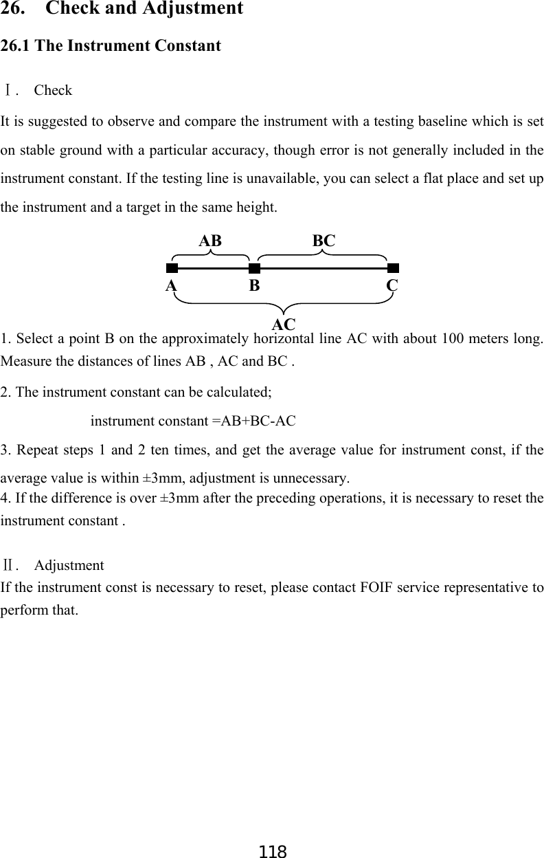
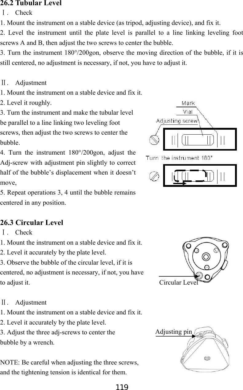
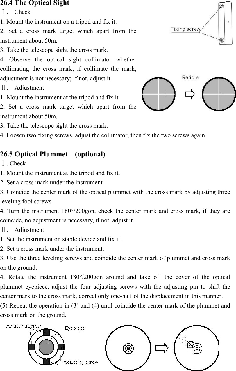
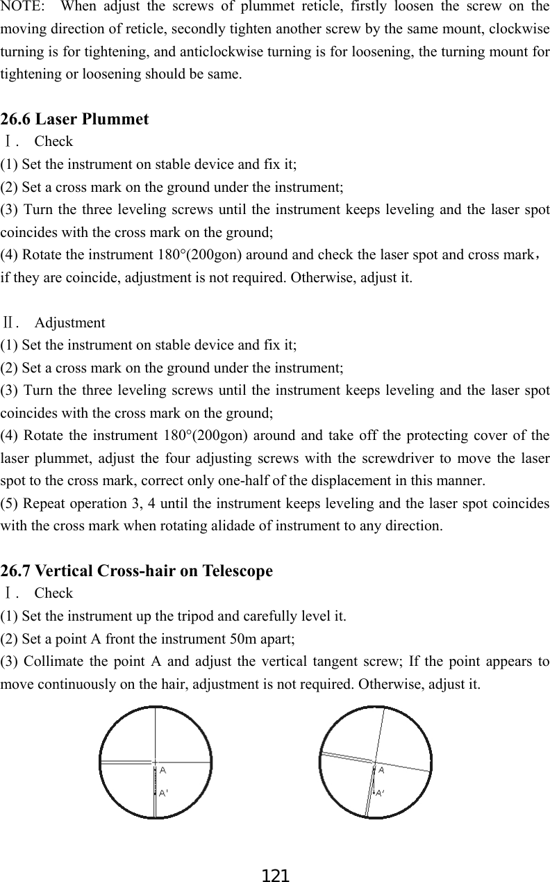
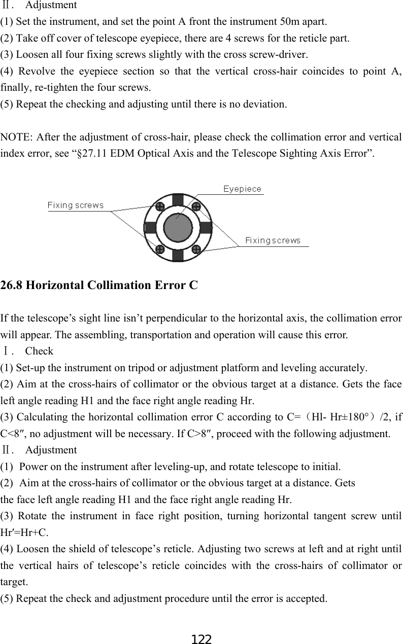
![123 NOTE: 1. When adjusting the screws of reticle, firstly loosen the screw on the moving direction of reticle, secondly tighten another screw by the same mount, clockwise turning is for tightening, and anticlockwise turning is for loosening, the turning mount for tightening or loosening should be same. 2. After the reticle adjustment, it is necessary to adjust the vertical index error by program, see “§23.10 Vertical Index Error”. 26.9 Tilt Sensor If the tilt angle shown on the display shifts from tilt angle 0°(zero point), the instrument is not correctly leveled. This will adversely affect angle measurement. Perform the following procedures to cancel the tilt zero point error. . CheckⅠ Set-up the instrument on tripod or adjustment platform, and level it accurately. 1. Press F4: [0SET] twice to set HA to 0°on P1 in measure mode. Press ESC then press F4: [CNFG] to enter into config mode. 2. Select “3.Inst adjust” to set instrument basic parameters, two items display. 3. Select “1. Tilt correct”. 4. Wait a few seconds for this display to stabilize, then read the automatically compensated angles X1 and Y1. X -0.0020gon HA 127.1202gon Take F1 0OK0 Config P1 1.Meas condition 2.Inst. config 3.Inst. adjust 4.Com setting 5.Unit Inst. adjust 1.Tilt correct 2.Collimation corre](https://usermanual.wiki/SUZHOU-FOIF/RTS102/User-Guide-2520405-Page-128.png)
![124 5. Rotate the instrument 180°/200gon. Loosen the horizontal clamp and turn the instrument 180°/200gon while referring to the displayed horizontal angle, then re-tighten the clamp. Wait a few seconds for the display to stabilize, then read the automatically compensated angles X2 and Y2. Calculate the following offset values (tilt zero point error): Xoffset= (X1+X2)/2 Yoffset= (Y1+Y2)/2 When the offset value falls within the range ±20″, adjustment is not necessary. If one of the offset values (Xoffset, Yoffset) exceeds ±20″, adjust the value as follows. . AdjustmentⅡ 6. Press F3: [OK] to set the horizontal angle to 0°, “Take F2” is displayed. 7. Rotate the top of instrument 180°/200gon. Wait a few seconds for the display to stabilize, then press F3: [OK]. 8. If both correction constant are in the range, press F3: [YES] to renew the correction angle, or press F4: [NO] to give up this adjustment, 26.10 Vertical Index Error The deviation between vertical circle zero position and horizontal direction is vertical index (i), it is necessary to concern this error when measure vertical angle. The instrument program applied a formula to correct this error. Warning: Before starting this operation, be sure to read this manual carefully, otherwise it may cause data faulty. Because of the close relationship between vertical index and compensator zero position, it is necessary to check and adjust compensator zero position before adjusting vertical circle, the value should be stable when reading. I X -0.0008gon HA 127.1202gon Take F2 0OK0 X -0.0008gon HA 127.1202gon Take F2 0OK0 X Old 0.0020gon X New 0.0006gon Set ? YES NO0](https://usermanual.wiki/SUZHOU-FOIF/RTS102/User-Guide-2520405-Page-129.png)
![125 . Check:Ⅰ Please adjust the reticle of telescope and correct the collimation error before this operation. (1) Mount the instrument at the tripod or a stable device and level it accurately, then turn on the instrument. (2) Aim at the cross-hairs of collimator or the obvious target at a distance, VA should be about ±10°. Read the face left angle Vl and face right angle Vr. (3) Calculate the index error according to the formula below: i = ( Vl+Vr-360°)/2 (4)If I<10〞 , no adjustment is necessary , or you have to adjust it . . Adjustment by program:Ⅱ Set-up the instrument on tripod or adjustment platform, and level it accurately. 1. press F4: [CNFG] to enter into config mode. 2. Select “3.Inst adjust” to set instrument basic parameters. Two items display. 3. Select “2.Index error correct”. 4. Sight a reference point in face I and press F3: [OK]. 5. Sight the reference point in face II. Rotate the instrument 180°/200gon and sight the same point, then press F3: [OK]. Config P1 1.Meas condition 2.Inst. config 3.Inst. adjust 4.Com setting 5.Unit Inst. adjust 1.Tilt correct 2.Collimation corre I VA 95.8860gon HA 115.4506gon Take F1 0OK0 II VA 295.8860gon HA 115.4506gon Take F2 0OK0](https://usermanual.wiki/SUZHOU-FOIF/RTS102/User-Guide-2520405-Page-130.png)
![126 6. Press F3: [YES] to set the correction, and press F4: [NO] to give up. 26.11 EDM Optical Axis and the Telescope Sighting Axis Error It is necessary to check this error after the adjustment of telescope reticle error. . Check (For ⅠRTS100 series) (1)Install the instrument at the tripod or a stable device and level it accurately, then turn on the instrument’s power on. (2) Set a prism about 2m far away from the instrument. (3) Aim at the prism center with telescope reticle (4) Enter EDM signal testing screen, see “§4.7 Setting Mode”. (5) Observe through eyepiece, turn the focusing knob until the read mark is clear, if the deviation between mark and cross-hair is not over 1/5 of red mark diameter, adjustment is unnecessary. . Check (For ⅡRTS100R series) (1) Install the instrument at the tripod or a stable device and level it accurately, then power on the instrument. (2) Set a reflective sheet about 5m-20m far away from the instrument. (3) Aim at the sheet cross-mark with telescope reticle. Index Error Old 0.0048gon New 0.0012gon Set ? YES NO0](https://usermanual.wiki/SUZHOU-FOIF/RTS102/User-Guide-2520405-Page-131.png)