Saab TransponderTech R5-AIS R5 SUPREME AIS User Manual Manual
Saab TransponderTech AB R5 SUPREME AIS Manual
UserManual.wiki
>
Saab TransponderTech
>
R5-AIS User Manual
>
Manual
Contents
1.
manual
2.
Manual
Manual
Navigation menu
Upload a User Manual
Namespaces
Wiki Guide
HTML
PDF
Info
Views
User Manual
Discussion / Help
Navigation

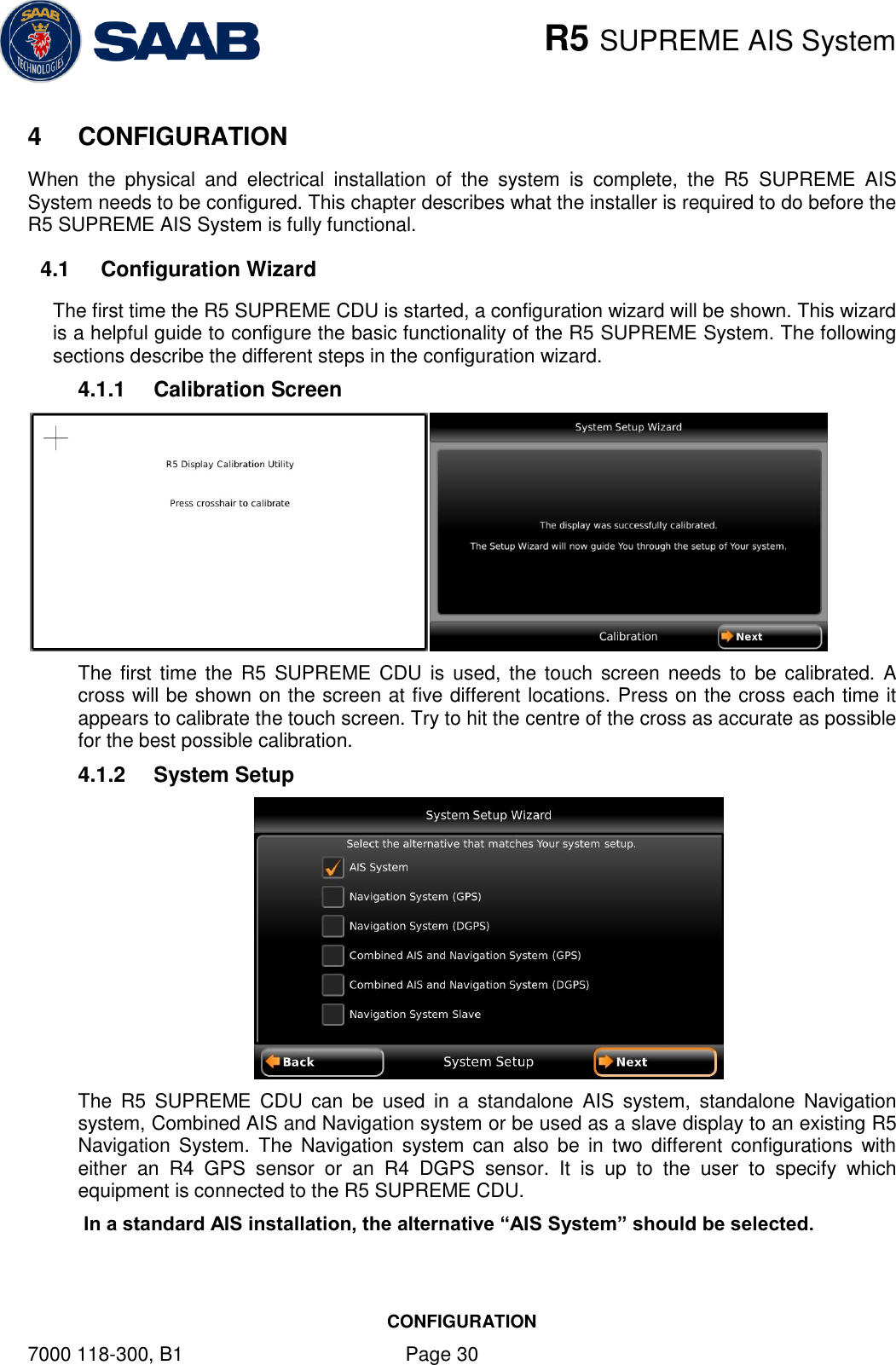
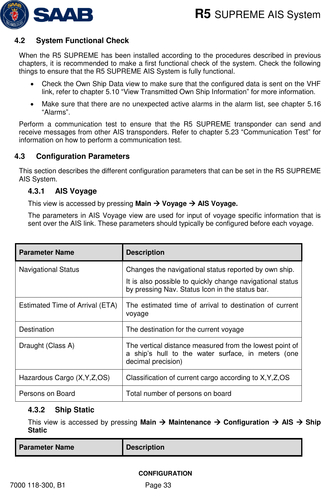
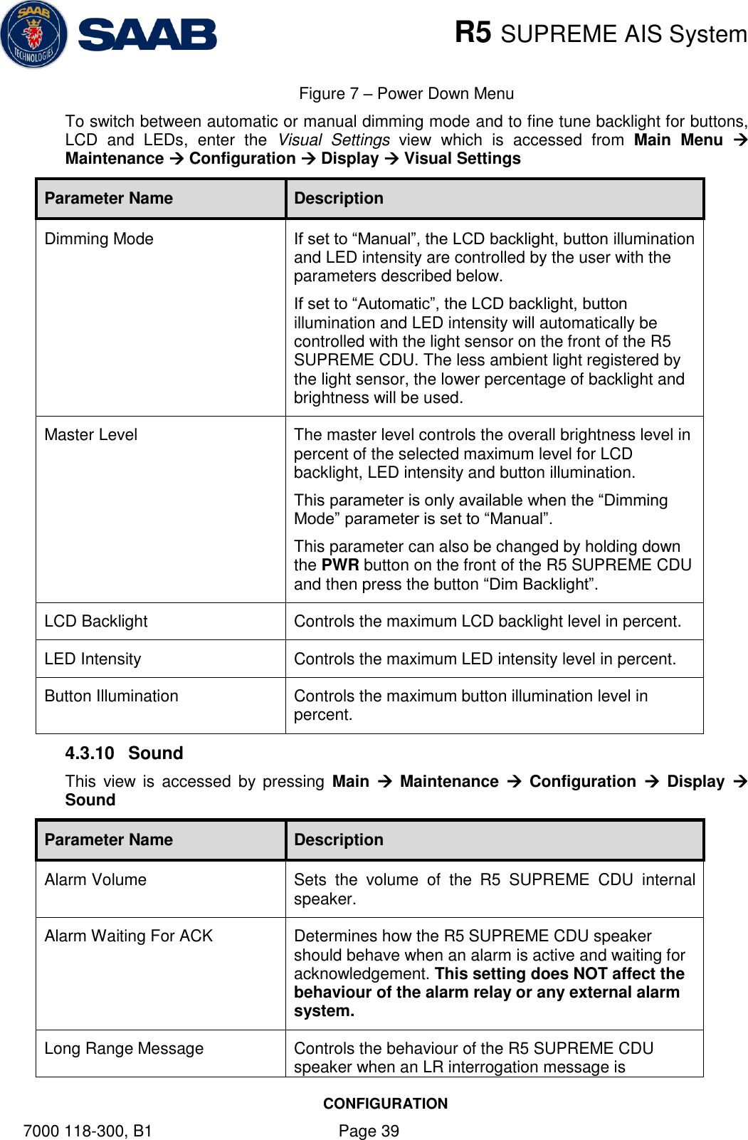
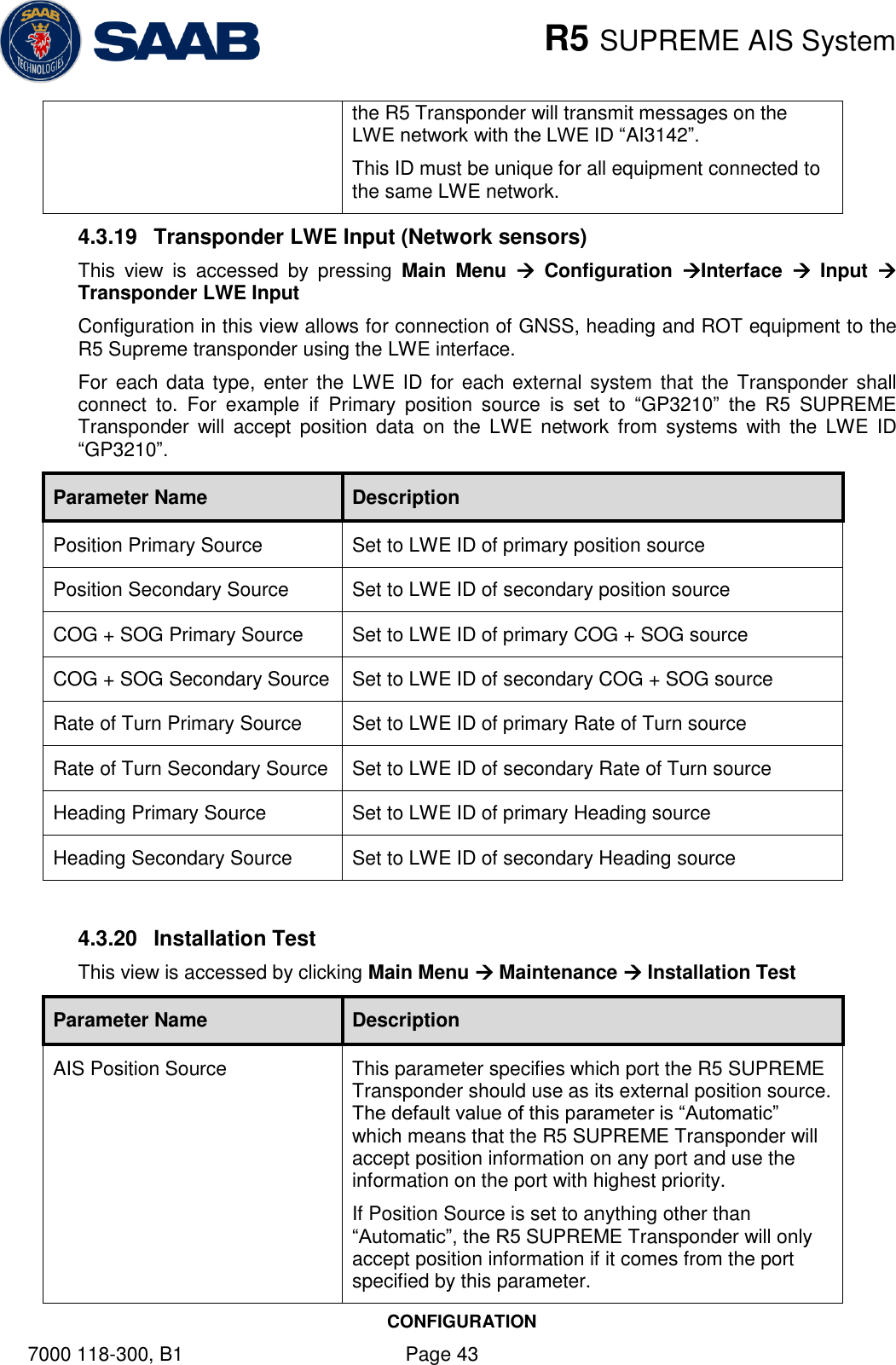
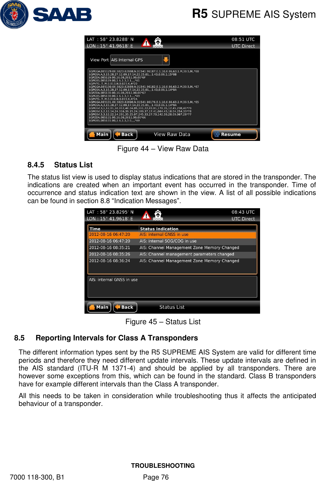
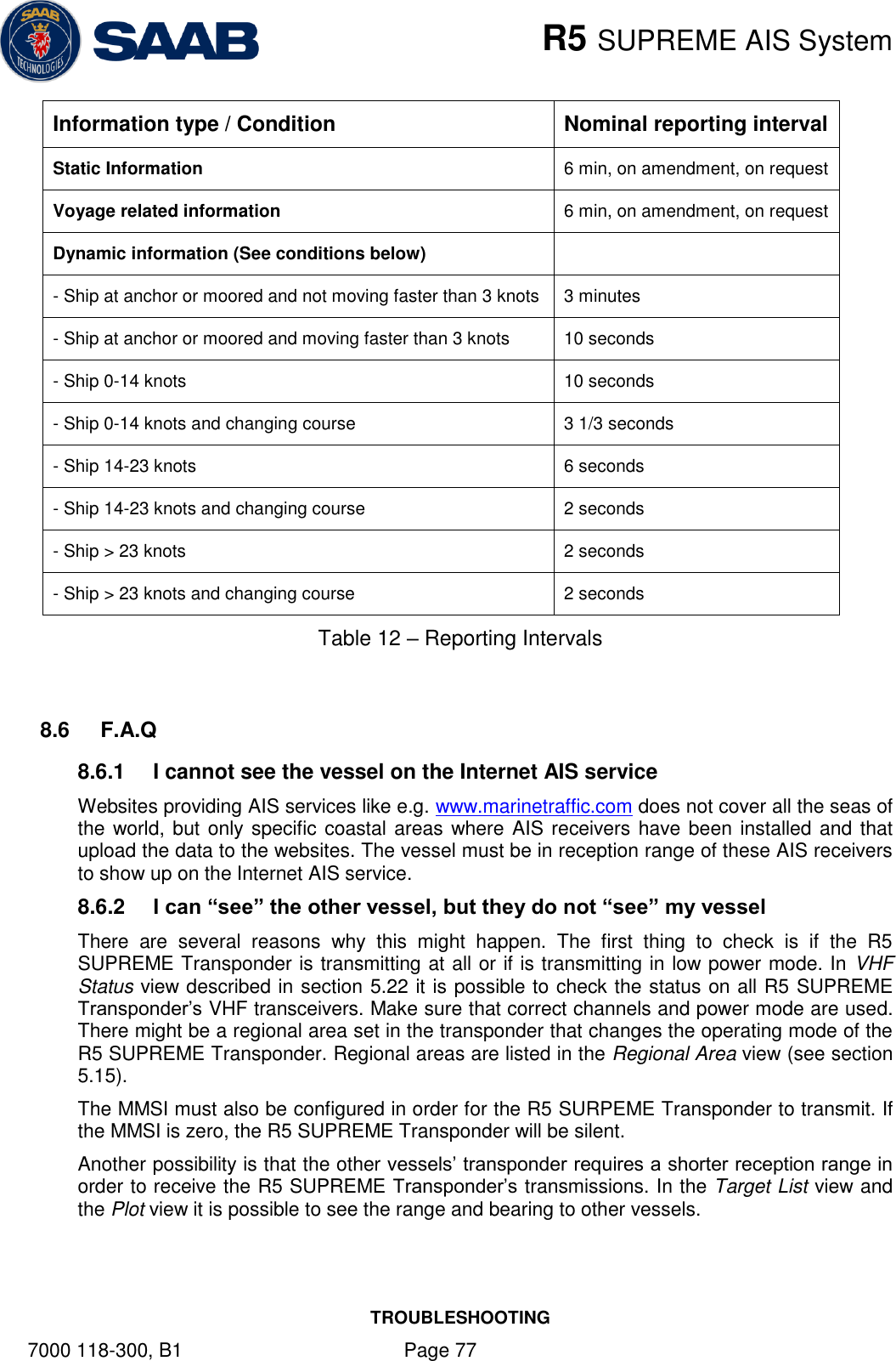
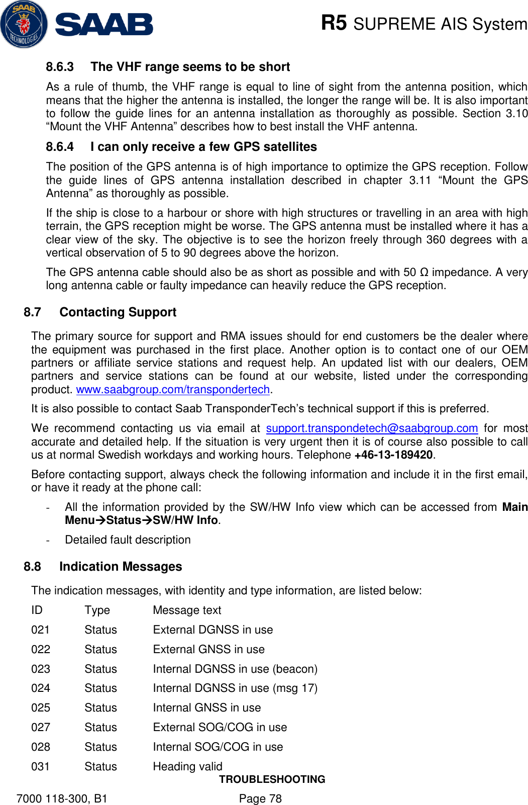
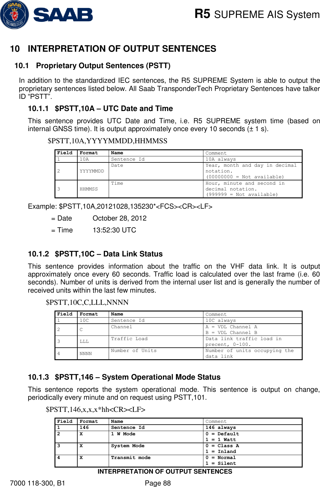
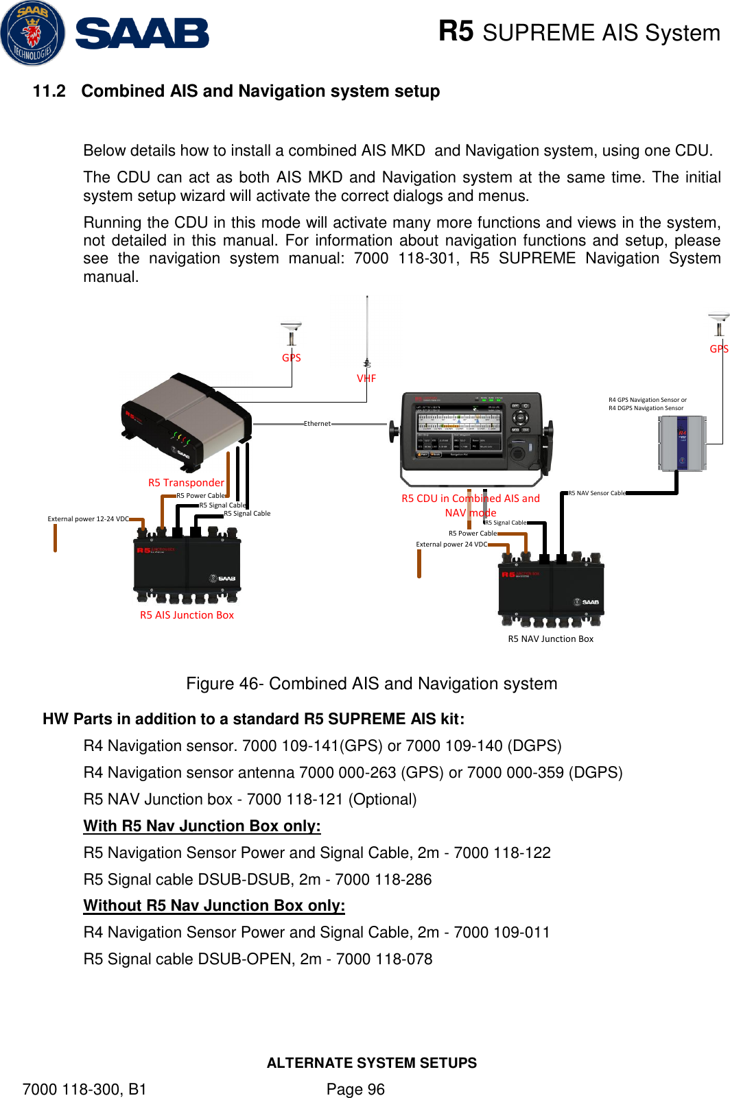
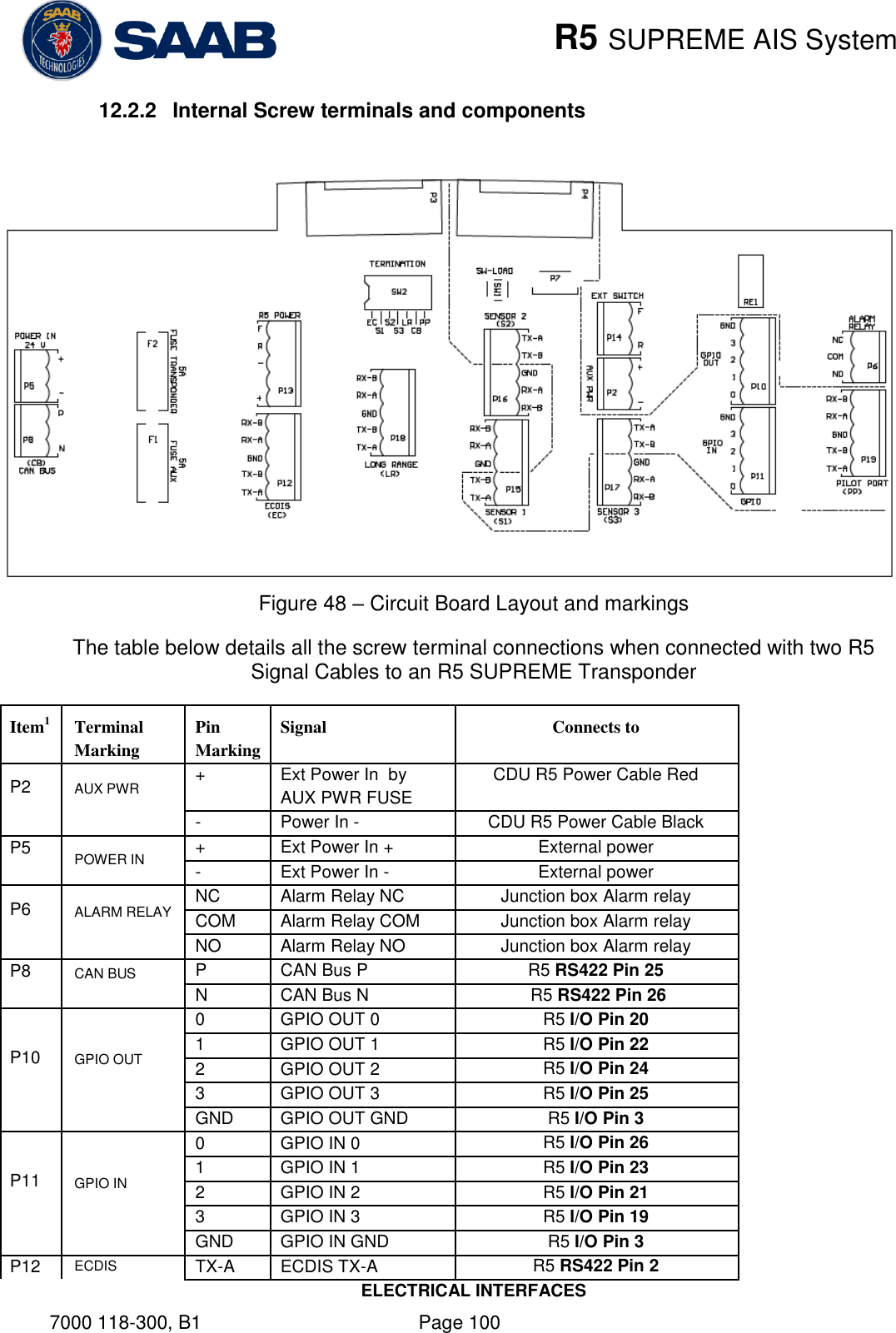
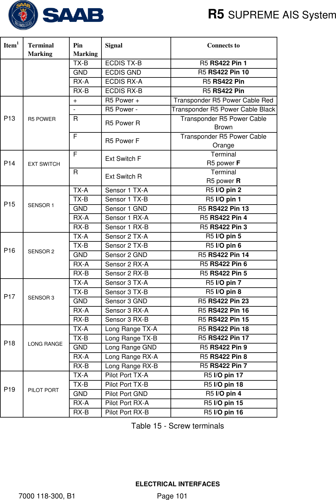
![R5 SUPREME AIS System CONFIGURATION 7000 118-300, B1 Page 34 MMSI Maritime Mobile Service Identity reported by own ship IMO International Maritime Organization number reported by own ship Ship Name Ship name reported by own ship Call Sign Call sign reported by own ship Height over Keel Height over keel in meters (one decimal precision). Height over Keel information is sent as a response to an “Extended Ship Static and Voyage Related Data” request message. Ship Type (IMO) Type of Ship according to ITU 1371-4. Both numerical input and selection from list is possible. 4.3.3 Ship Dimensions This view is accessed by pressing Main Maintenance Configuration AIS Ship Dimensions The parameters in the Ship Dimensions view depends on the configuration parameter “Ship Size Mode” in the Misc. Interfaces view. The Ship Size Mode parameter can be set to either Standard or Simplified (default). The Ship Size Mode affects how the user should input ship size and antenna position information and how it is interpreted. Standard Mode In this mode the user must input: A, B, C, D for internal antenna [m] A, B, C, D for external antenna [m] Simplified Mode (default) In this mode there is no way for the user to input mismatching data, all parameters uses the same precision and each measurement is entered only once (in standard mode it is for example possible to enter three different length of ship: Convoy/ship length, internal A+B and external A+B). In simplified mode the transponder will automatically calculate and correctly round the A, B, C and D values reported on the VHF link.](https://usermanual.wiki/Saab-TransponderTech/R5-AIS.Manual/User-Guide-1980818-Page-34.png)
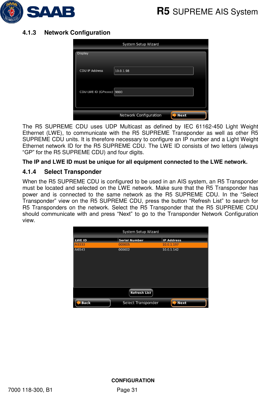
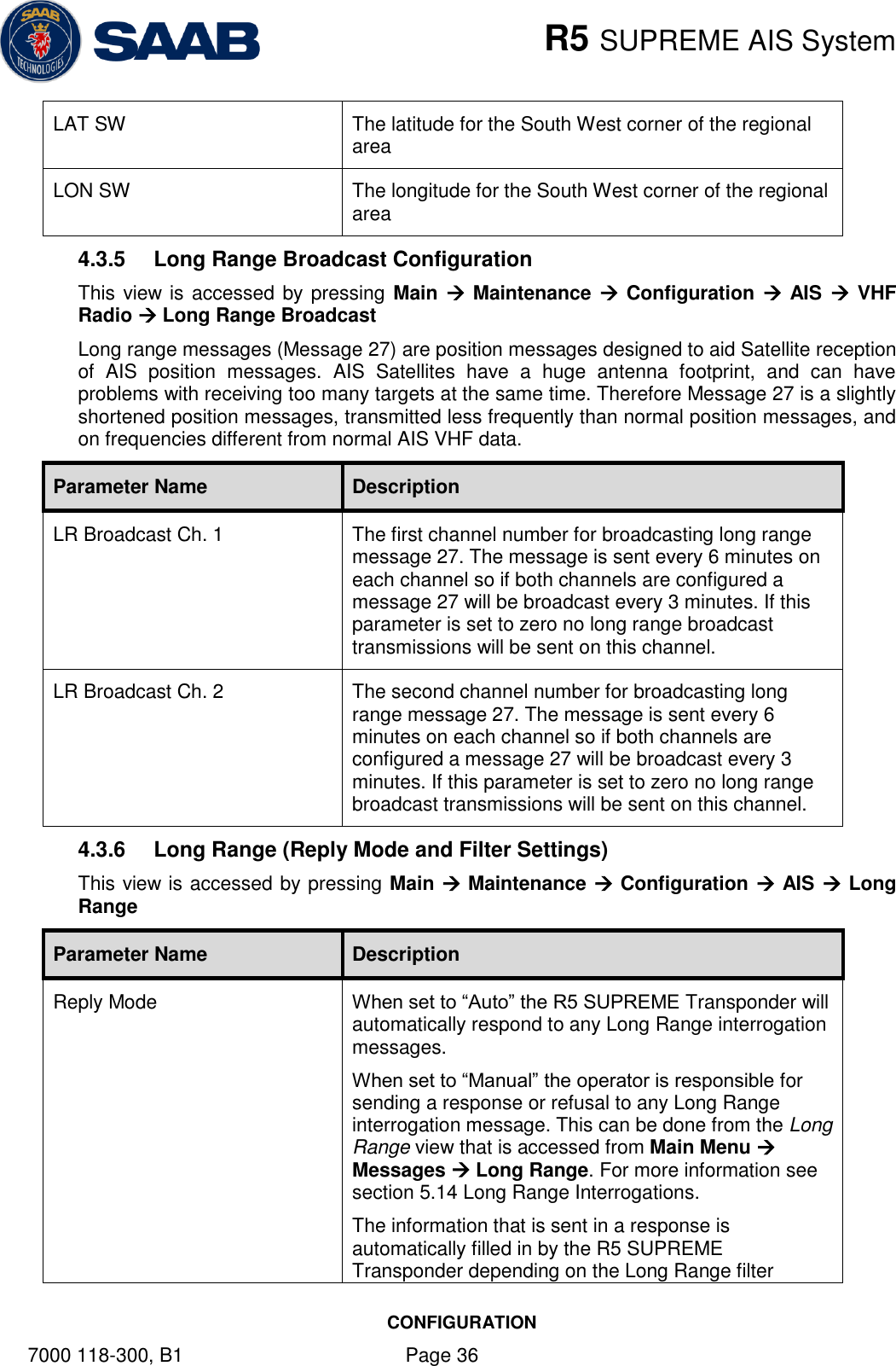
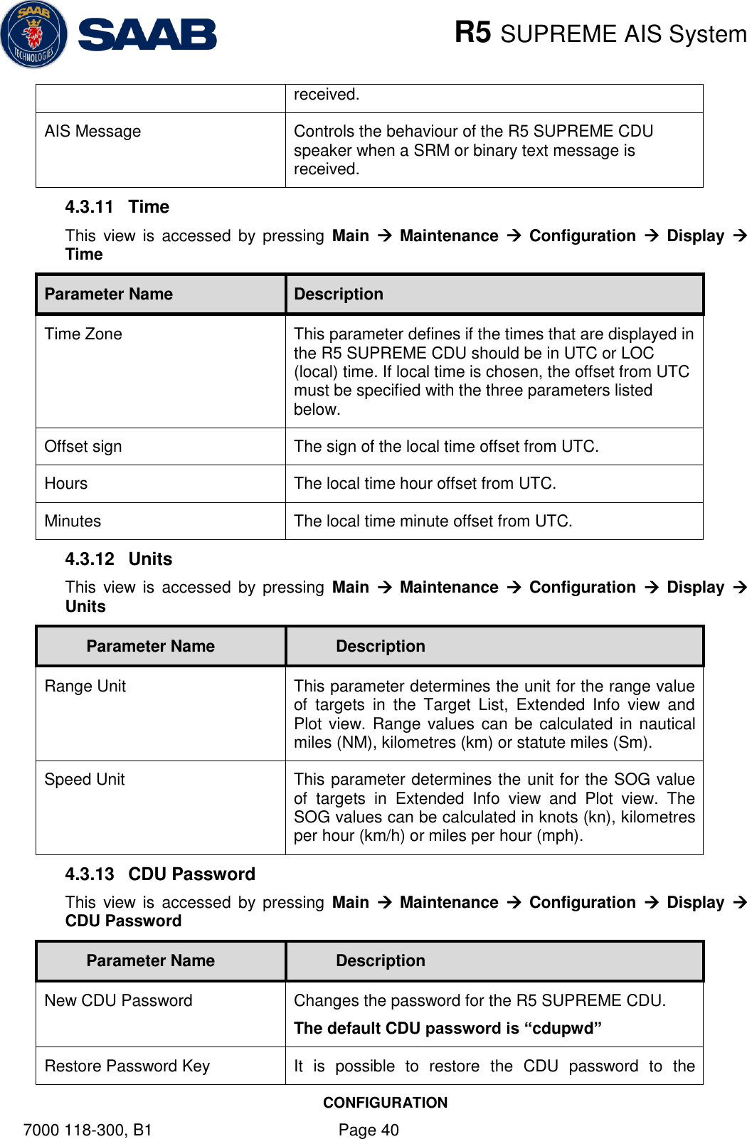
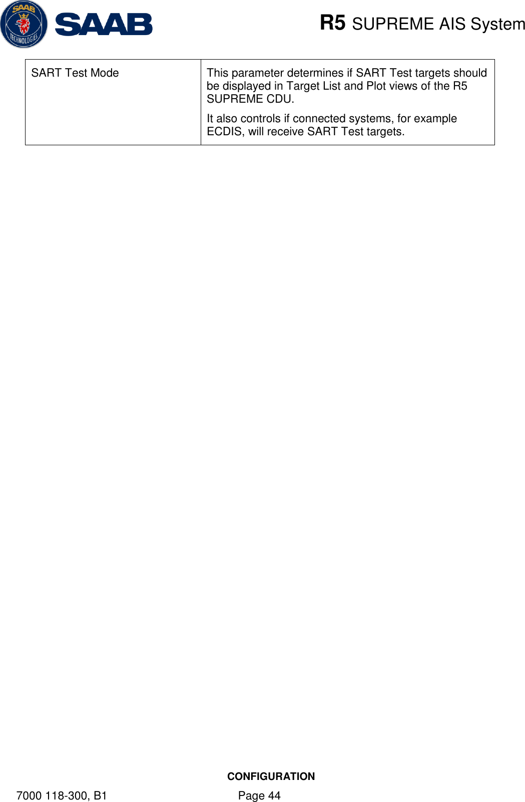
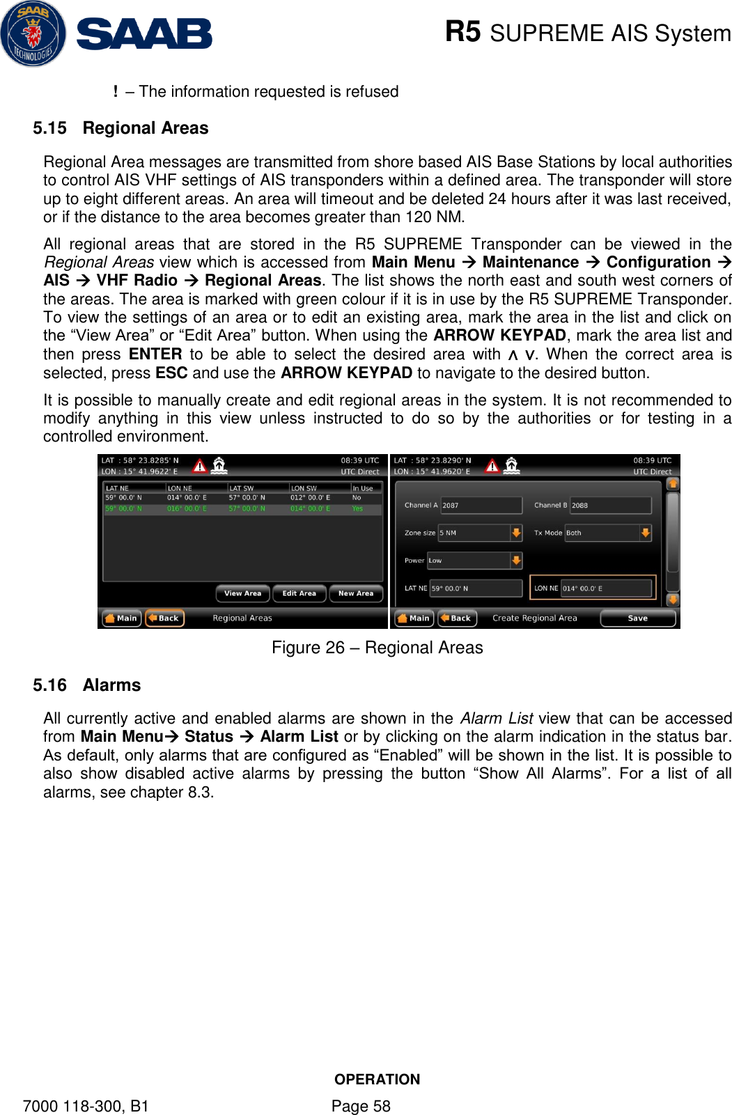
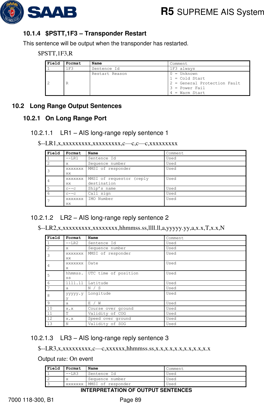
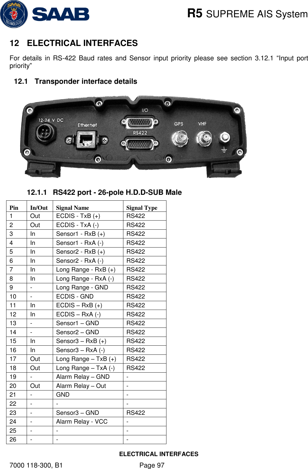
![R5 SUPREME AIS System CONFIGURATION 7000 118-300, B1 Page 35 In this mode the user inputs: Ship length [m] (one decimal precision) Ship beam [m] (one decimal precision) X, Y for internal antenna relative to ship [m] (one decimal precision) X, Y for external antenna relative to ship [m] (one decimal precision) 4.3.4 Regional Areas This view is accessed by pressing Main Maintenance Configuration AIS VHF Radio Regional Areas The view shows the regional areas set in the transponder. These are normally transmitted by an AIS base station to change AIS VHF nominal power level and/or frequencies in a specific area. When editing an area or creating a new area the following parameters can be configured: Parameter Name Description Channel A The channel number for AIS channel A (2087 = default) that should be used in the regional area Channel B The channel number for AIS channel B (2088 = default) that should be used in the regional area Zone Size The transitional zone size of the regional area in nautical miles (NM) Tx Mode Decides on which channels the transponder will use when transmitting in the regional area. When set to “Silent”, the transponder will stop automatic transmissions on AIS channels A and B. Power Output power for the transponder in the regional area. High = 12.5 W, Low = 1 W. LAT NE The latitude for the North East corner of the regional area LON NE The longitude for the North East corner of the regional area](https://usermanual.wiki/Saab-TransponderTech/R5-AIS.Manual/User-Guide-1980818-Page-35.png)
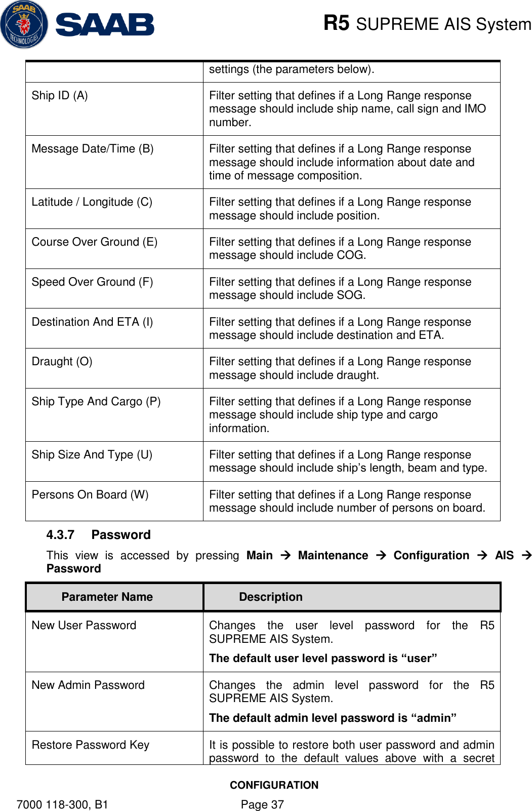
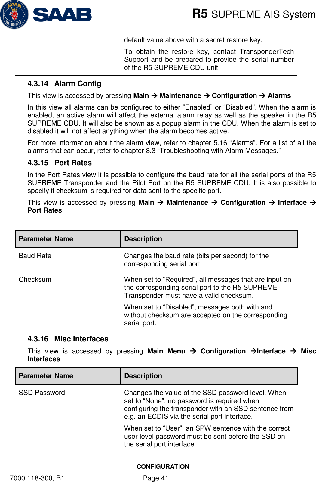
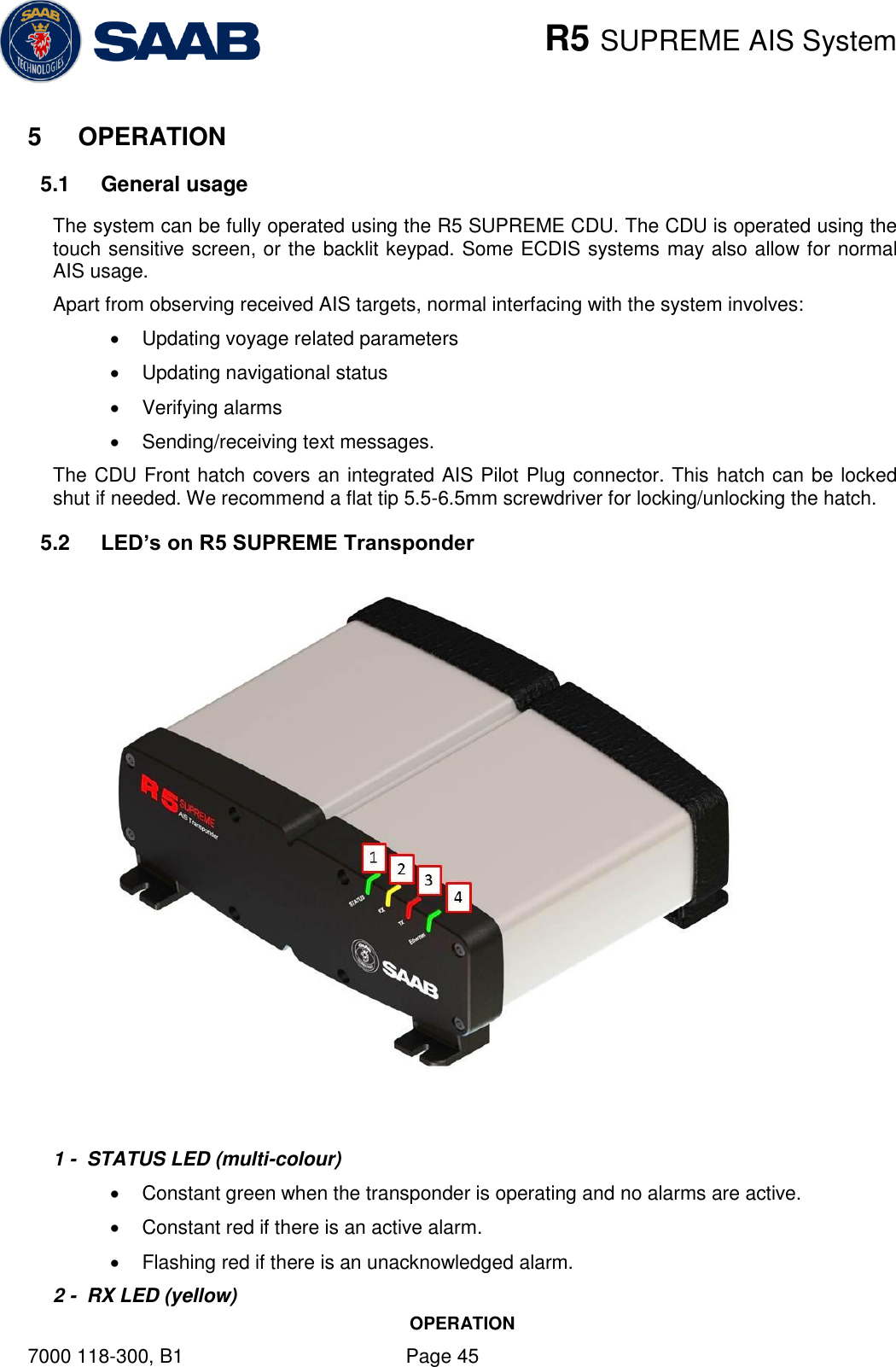
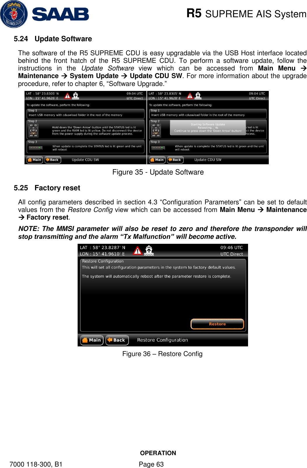
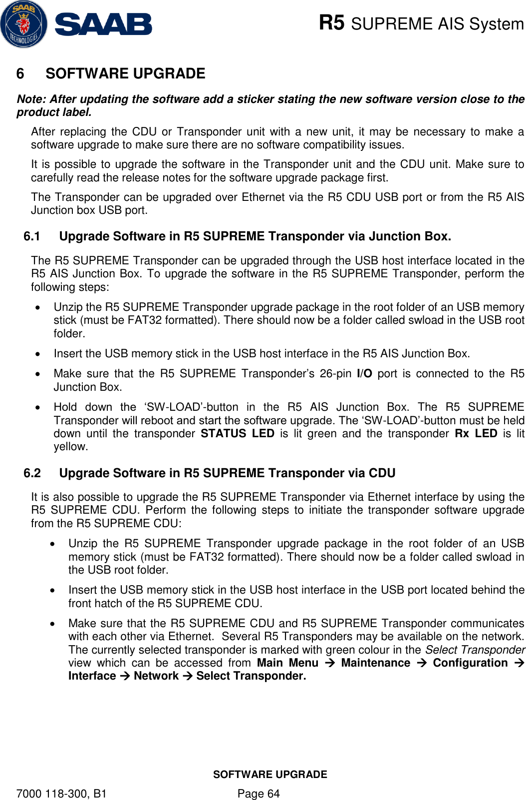
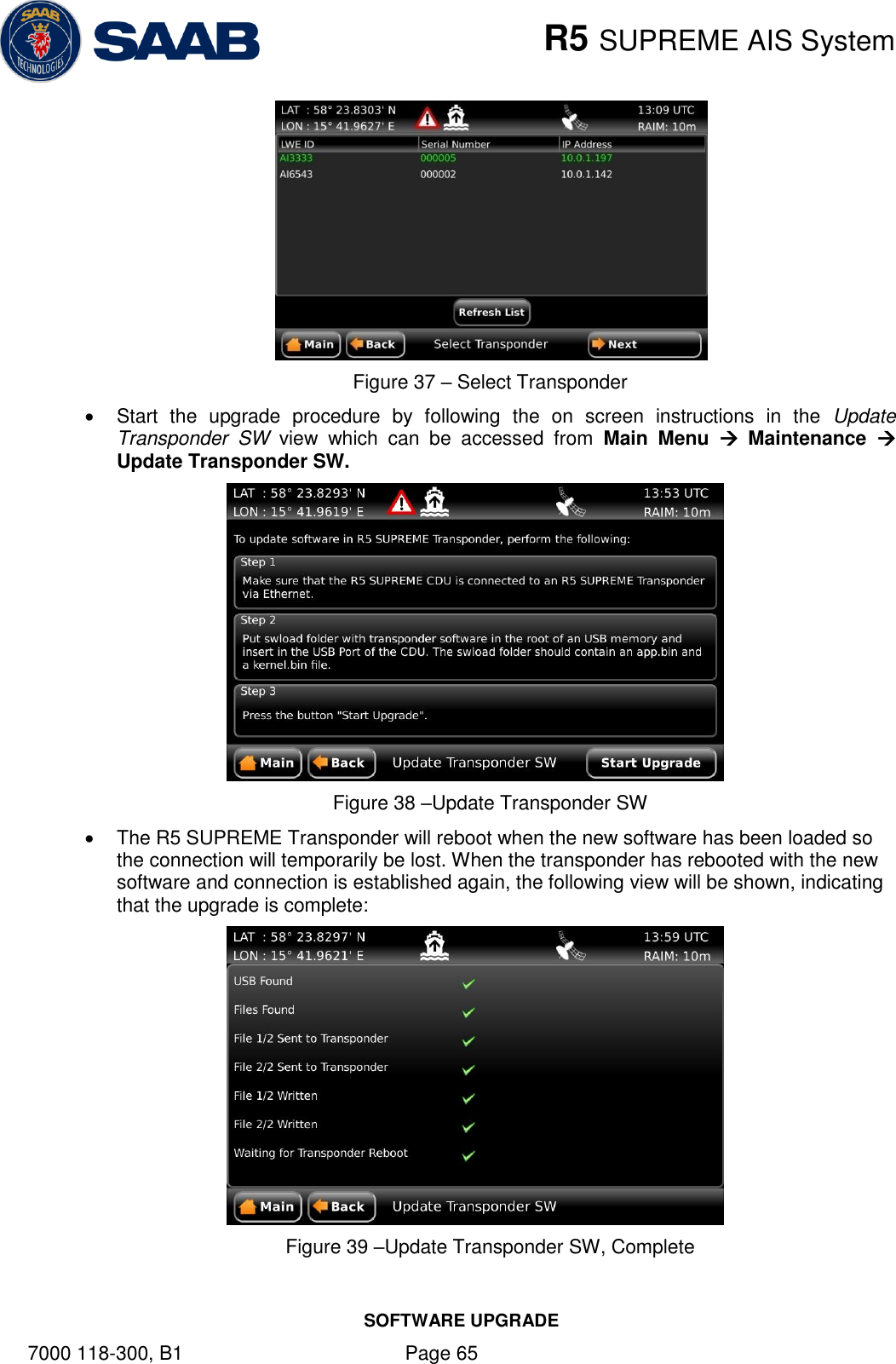
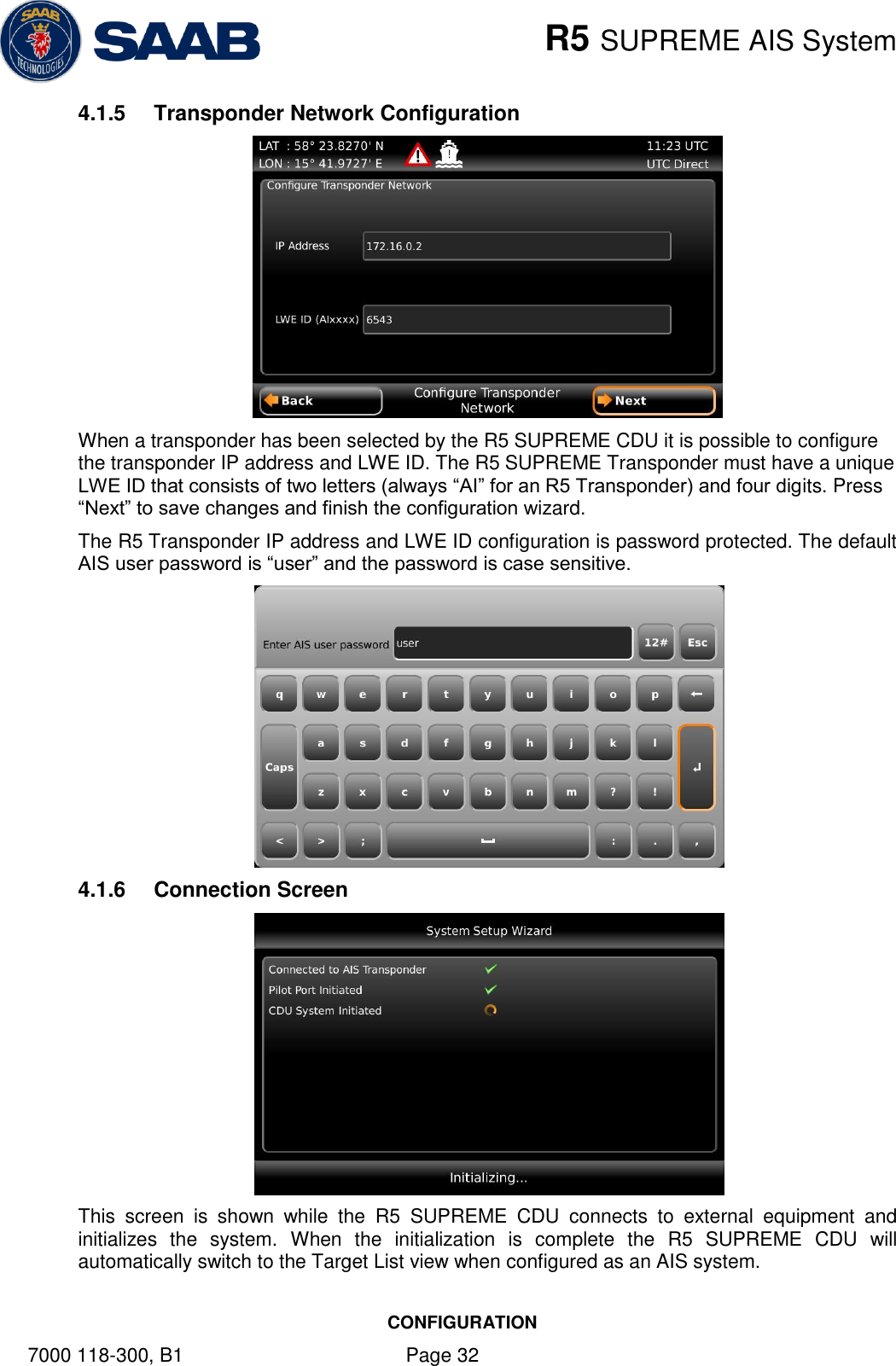
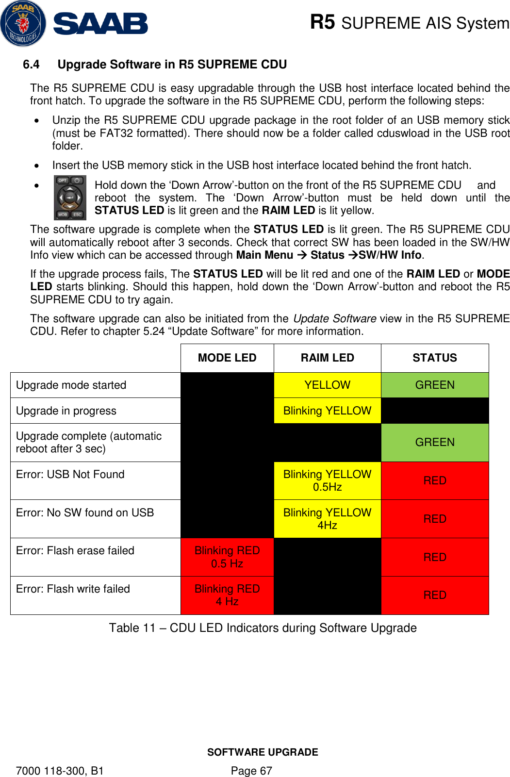
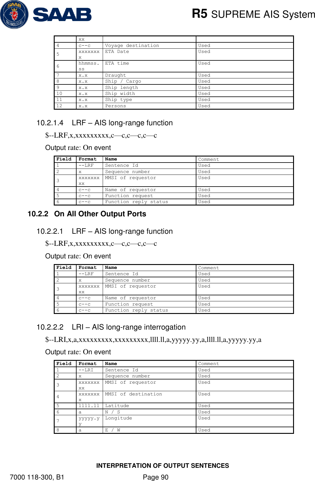
![R5 SUPREME AIS System SOFTWARE UPGRADE 7000 118-300, B1 Page 66 6.3 License Upgrade Some features in the R5 SUPREME AIS System are license controlled and needs to be unlocked by a special license file. A license file is unique for each single R5 SUPREME Transponder. The license file name has the following structure; 200001 - 7000 118-611 [Secure W-AIS].lic In this example: 200001 – The serial number of the R5 SUPREME Transponder unit this key works with. 7000 118-611 – The part number of this license key. To upgrade the license in the R5 SUPREME AIS System, perform the following: Place the license file in the root of a FAT32 formatted USB memory. It is possible to put many license files on the same USB memory if upgrading several units. Make sure that the R5 SUPREME CDU and R5 SUPREME Transponder communicates with each other via Ethernet. Several R5 Transponders may be available on the network. The currently selected transponder is marked with green colour in the Select Transponder view which can be accessed from Main Menu Maintenance Configuration Interface Network Select Transponder. Insert the USB memory in the USB host interface located behind the front hatch of the R5 SUPREME CDU. Enter the view Main Menu Maintenance System Update License and press the button “Update License”. If the license is successfully set, a number of unlocked modules will appear: Figure 40 –License Upgrade Successful If a correct license file cannot be found on the USB memory, the following will appear: Figure 41 – No License File Found](https://usermanual.wiki/Saab-TransponderTech/R5-AIS.Manual/User-Guide-1980818-Page-66.png)
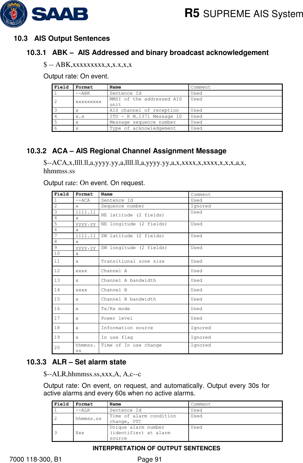
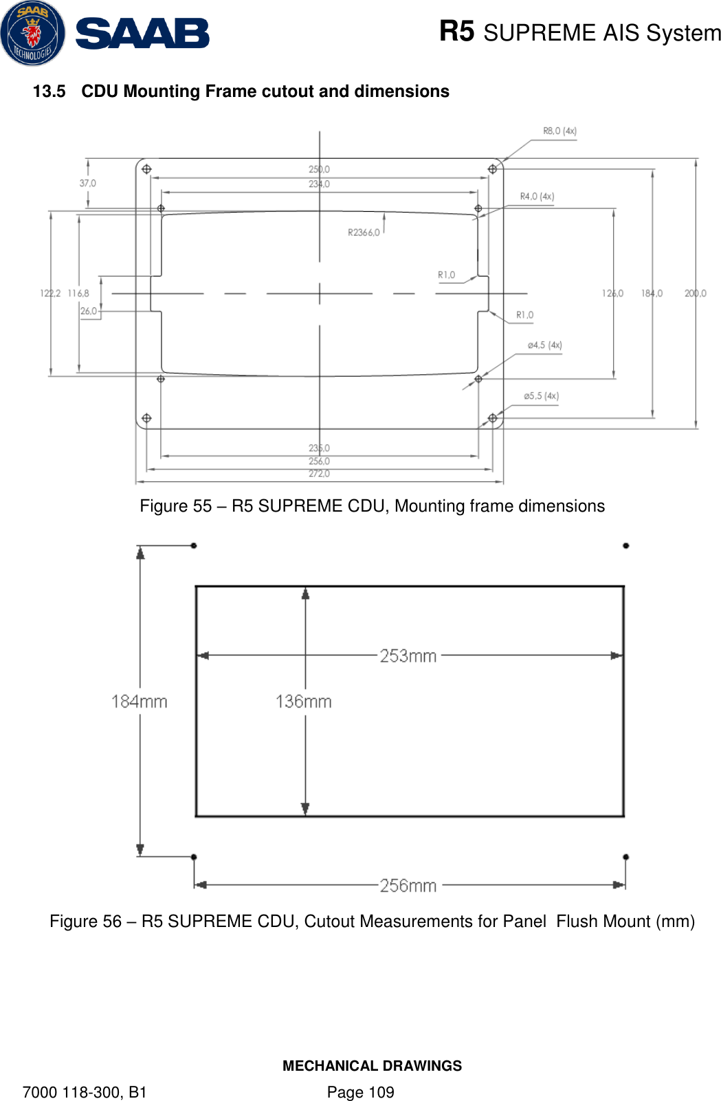
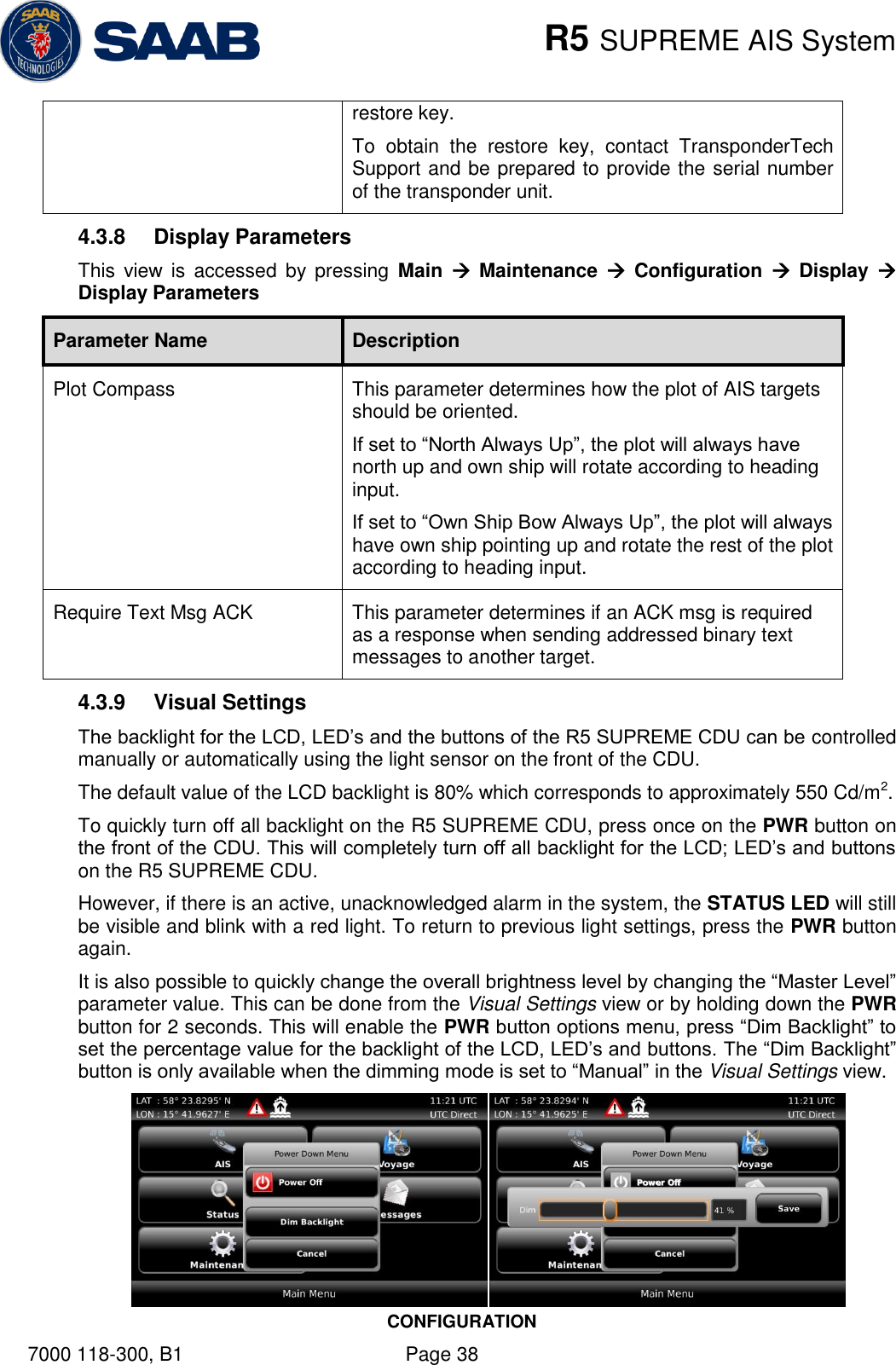
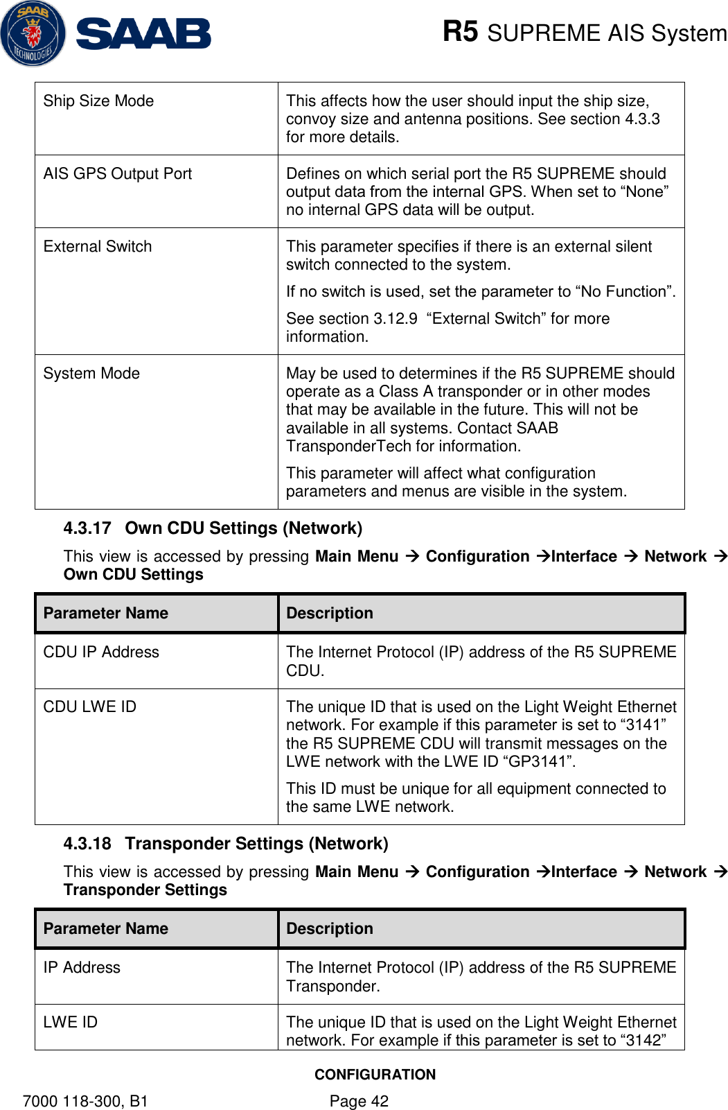
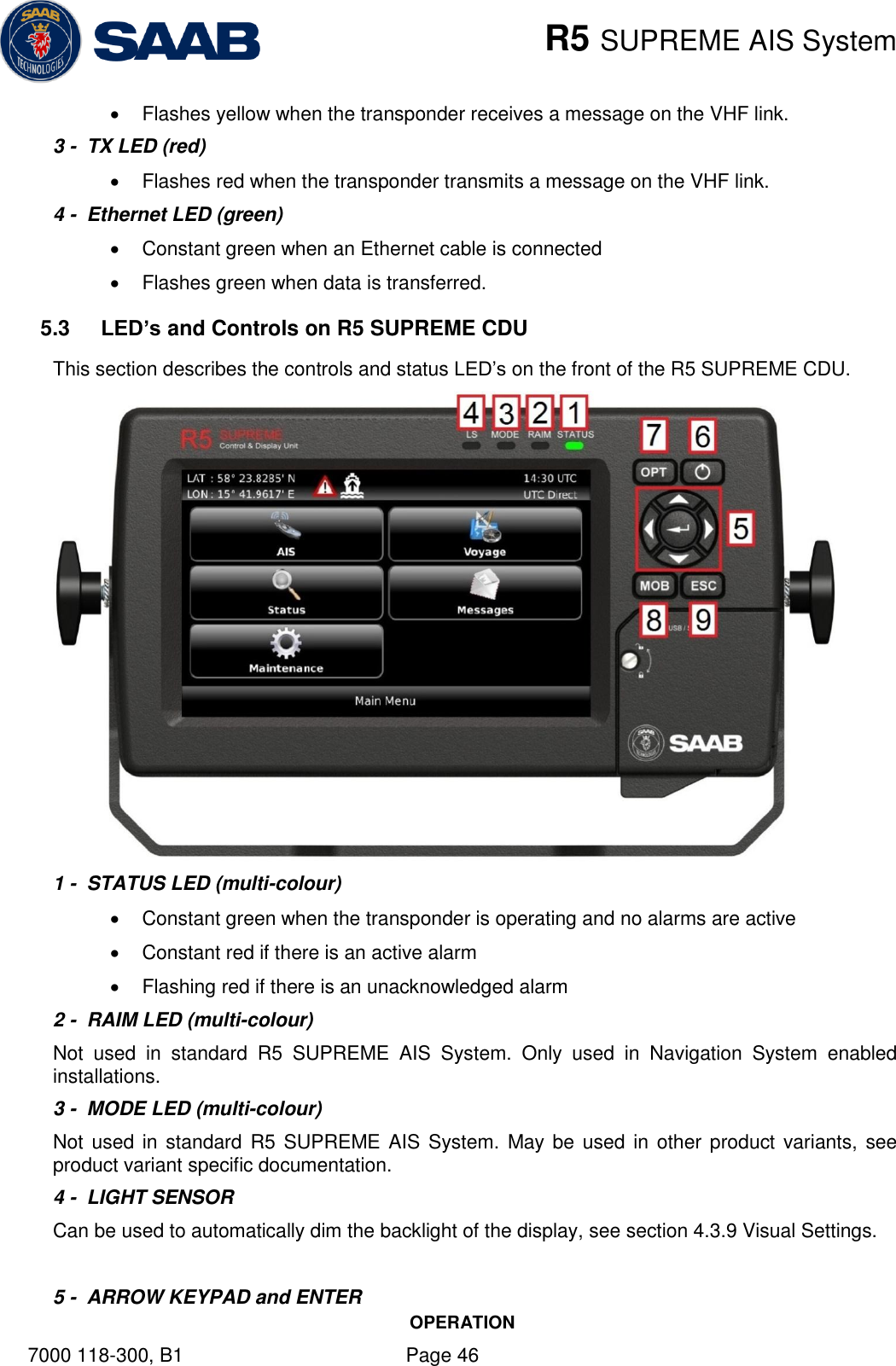
![R5 SUPREME AIS System MECHANICAL DRAWINGS 7000 118-300, B1 Page 108 13.4 CDU Cutout Measurements for Panel Mount Figure 54 – R5 SUPREME CDU, Cutout Measurements for Panel Mount [mm]](https://usermanual.wiki/Saab-TransponderTech/R5-AIS.Manual/User-Guide-1980818-Page-108.png)