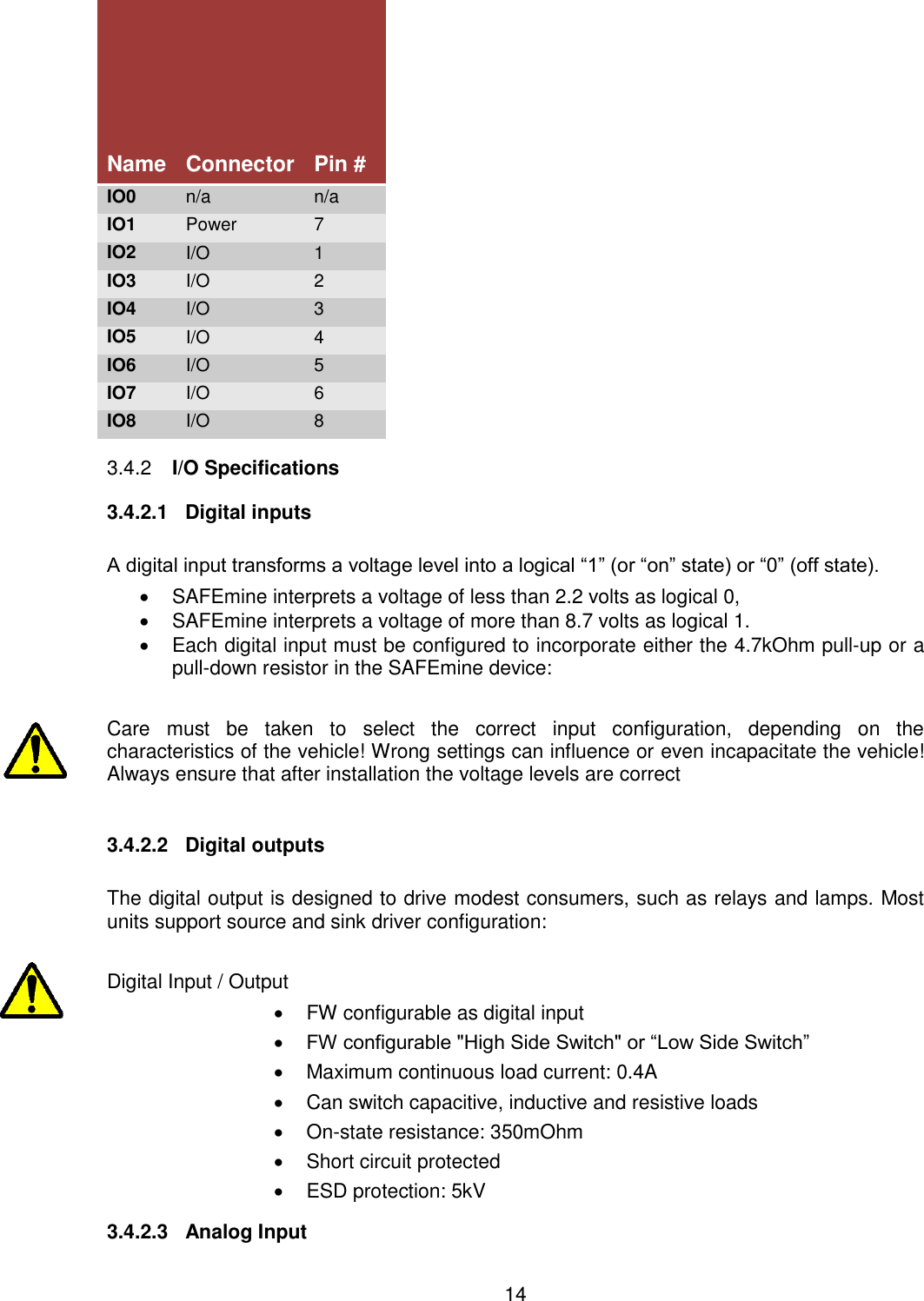
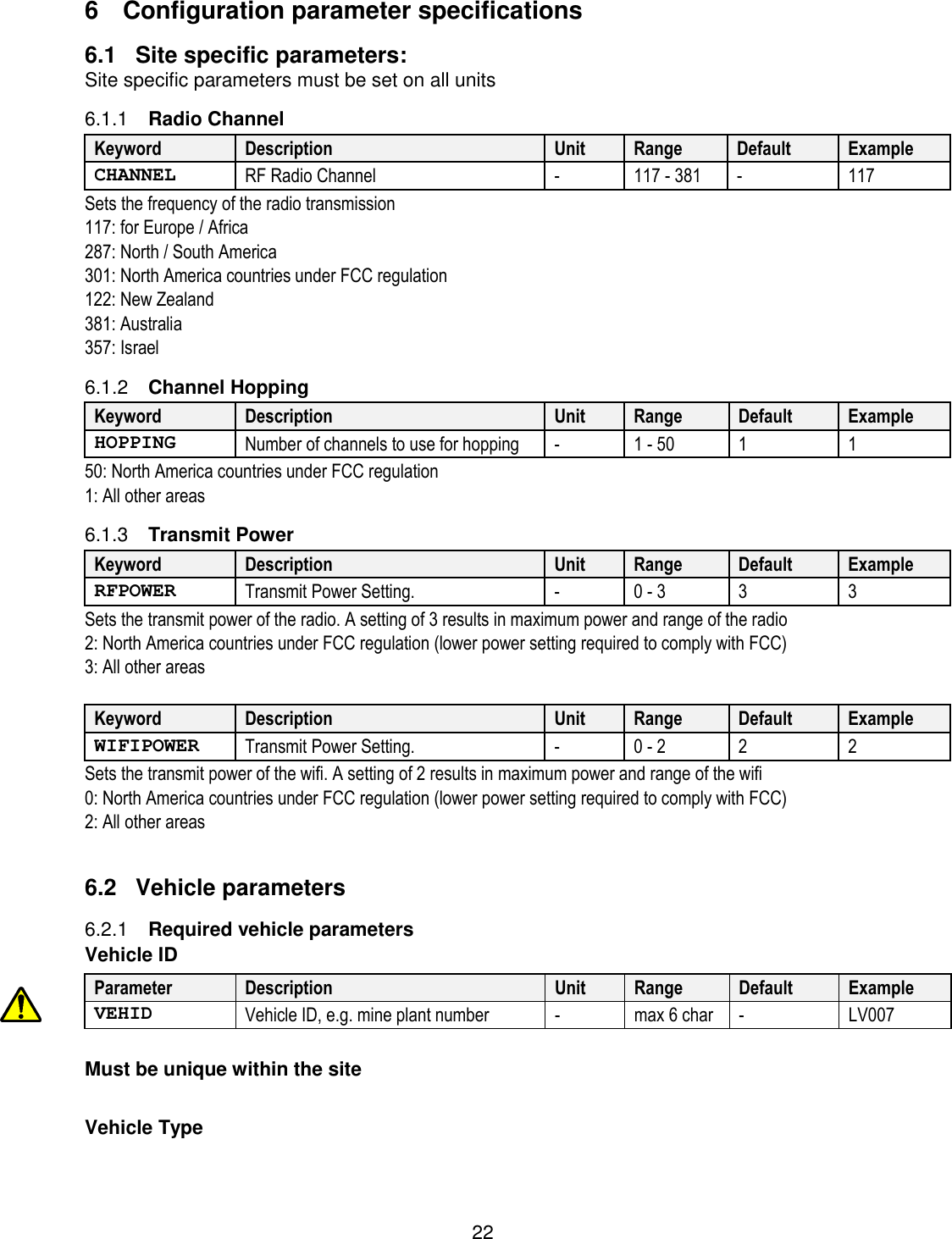
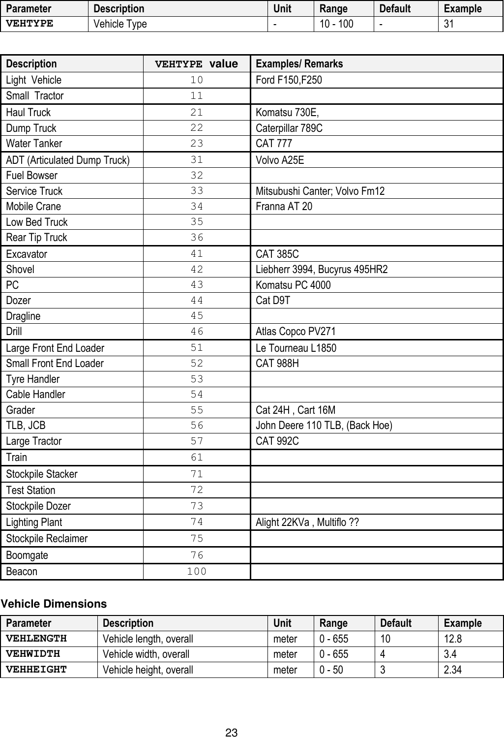
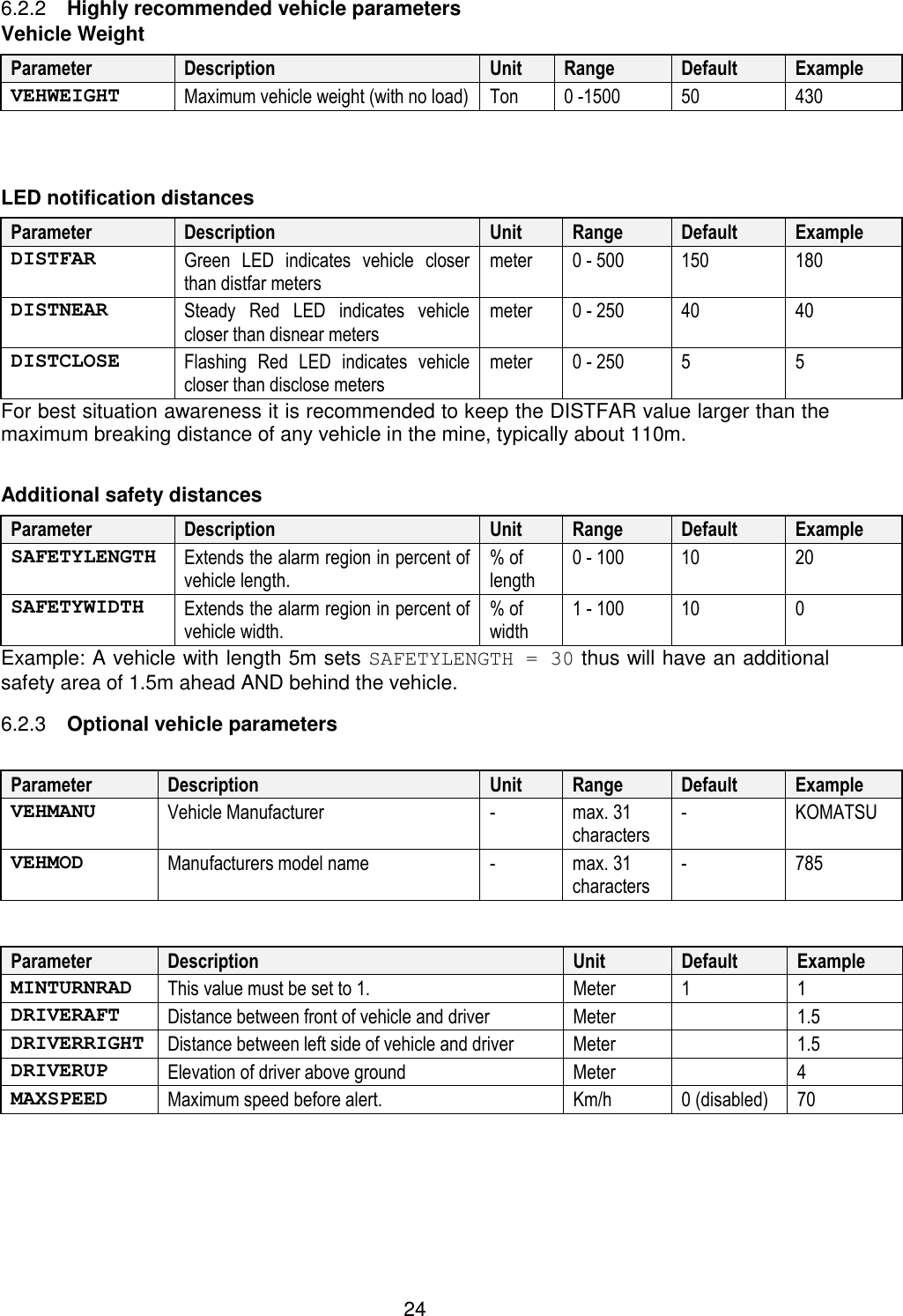
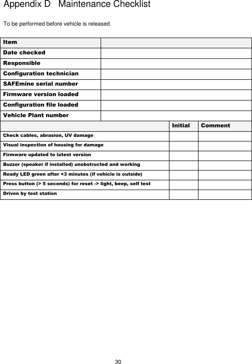
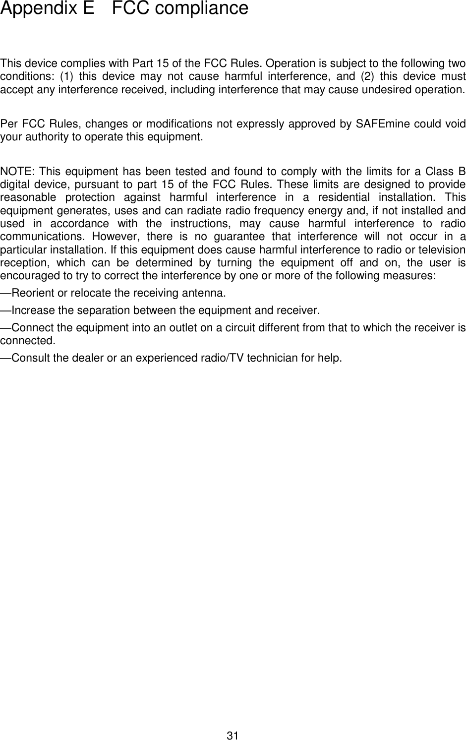
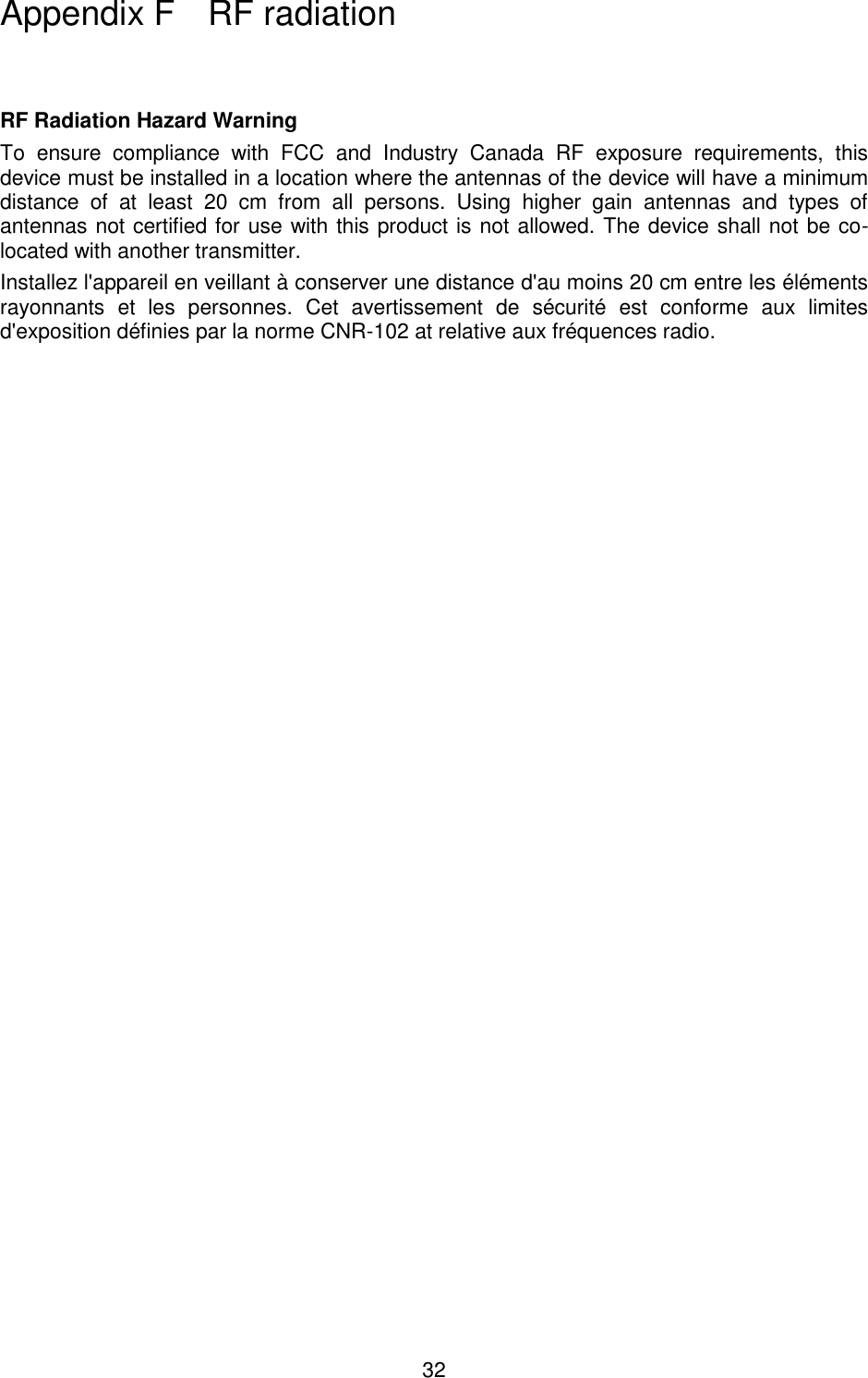
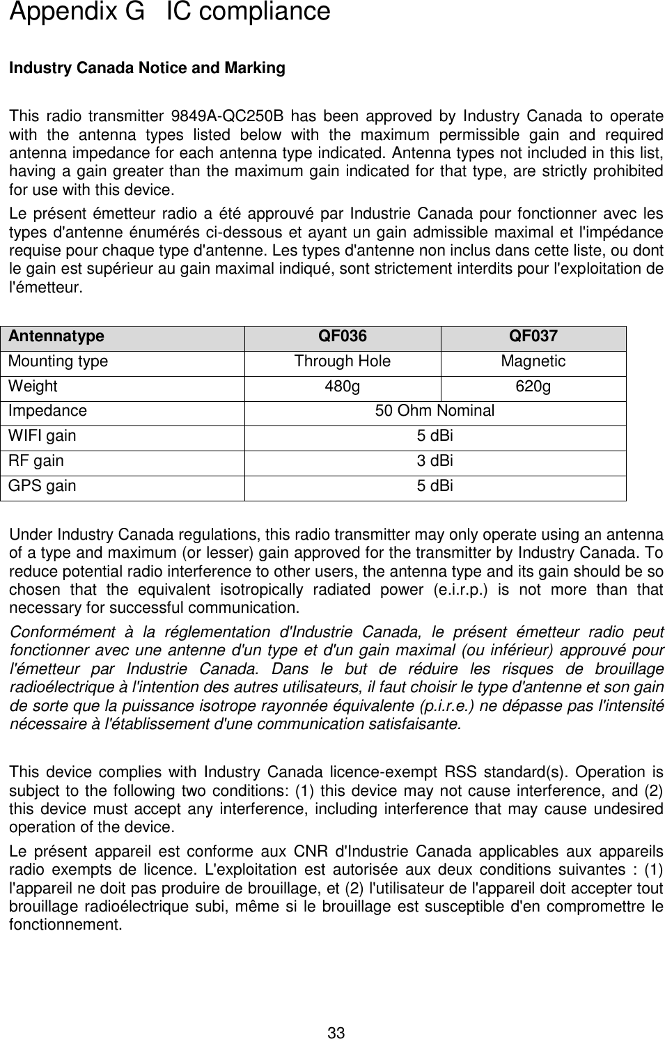
Safemine QC250B Collision Avoidance System User Manual UserManual

Safemine Ltd Collision Avoidance System UserManual

UserManual

1   ®  INSTALLATION AND MAINTENANCE GUIDE  for  SAFEmine COLLISION AVOIDANCE SYSTEMS   Firmware Version 2.61 SMTool version 2.0.7 July 31 , 2014 © 2009-2014 SAFEmine Ltd. Switzerland
2   Topic: This document is the reference manual for the installation,  configuration and operation of SAFEmine units and tools. Document  Nr: PRO_CAS_QC2_130207   Date: May 23, 2016   Disclaimer This  document  and  the  use  of  any  information  contained  therein,  is subject to the acceptance of the  SAFEmine terms and  conditions. They can be downloaded from www.SAFE-mine.com  SAFEmine makes no warranties based on the accuracy or completeness of the contents of this document and reserves the right to make changes to specifications and product descriptions at any time without notice.  SAFEmine  reserves  all  rights  to  this  document  and  the  information contained herein. Reproduction, use or disclosure to third parties without express permission is strictly prohibited. Copyright © 2012, SAFEmine. SAFEmine ® is a registered trademark   Version Control  Version Modifications PRO_CAS_QC2_101010 August 29th 2011   Original document  PRO_CAS_QC2_130207    Removed Appendix: Troubleshooting guide. Created a separate document   Added : the main unit enclosure and the metal shrouds of all connectors need to be electrically isolated from the vehicle  Added ‘To assist during installation the ‘Mode’ LED will turn  Red to indicate that the digital  output has gone high’ to Test Station and Boom gate chapters   SMTool manual was removed. A separate document was added   All features and changes introduced by FW 2.61 were added   Added QC250 specifications (no Wifi configuration)
3   1 SAFEmine device presentation ...................................................... 5 1.1 Objective .................................................................................................................... 5 1.2 Technology ................................................................................................................. 5 1.3 Limitations.................................................................................................................. 5 2 Safety ............................................................................................... 7 2.1 Operating precautions ............................................................................................... 7 2.2 Installation precautions ............................................................................................. 7 3 Hardware .......................................................................................... 9 3.1 Main units ................................................................................................................... 9 3.2 GPS & RF Antenna ..................................................................................................... 9 3.3 Technical specifications and interfaces ..................................................................10 3.4 I/O Connections ........................................................................................................13 4 Installation and operation ............................................................. 16 4.1 General advice ..........................................................................................................16 4.2 Main unit ....................................................................................................................16 4.3 Antennas ...................................................................................................................17 4.4 Antenna cables .........................................................................................................18 5 SAFEmine programming tool (SMTool ) ...................................... 21 5.1 Installation .................................................................................................................21 5.2 Firmware and Configuration File upload .................................................................21 6 Configuration parameter specifications ...................................... 22 6.1 Site specific parameters: ..........................................................................................22 6.2 Vehicle parameters ...................................................................................................22 7 Advanced Troubleshooting .......................................................... 26 7.1 Error codes................................................................................................................26 Appendix A Declaration of conformity.......................................... 27 Appendix B Specifications (QC250) .............................................. 28 Appendix C Additional figures and drawings............................... 29 Appendix D Maintenance Checklist .............................................. 30 Appendix E FCC compliance ......................................................... 31 Appendix F RF radiation ................................................................ 32 Appendix G IC compliance ............................................................ 33 Appendix H Legal statement ......................................................... 34
4     SECTION A Introduction
5  1  SAFEmine device presentation 1.1  Objective The  main  task for  SAFEmine  QC250  series  products  is  to  support  the  operator  while  he scans the space ahead and around the vehicle with his own eyes, cameras and other aids. SAFEmine products are simple to use and are designed not to distract the  operator from operating the vehicle. 1.2 Technology The SAFEmine system – based on technology widely used in aviation – consists of a main unit, an operator's interface (both output and input) and a dual antenna (one for GPS, one for  radio  communication).  Depending  on  the  product  selected,  the  operator's  interface  is either  integrated  into the main  unit or  mounted  as  a  separate display unit. The  main unit contains  all  main  sensors  (GPS  engine,  radio  transceiver,  micro-controller,  memory,  data interfaces and a series of sensors), The operator interface provides both a directional display of nearby traffic and danger, the beeper/loudspeaker for acoustical warnings and one button for input. SAFEmine  QC250  series  products  receive  position  and  movement  information  from  an internal  high-sensitivity  50  channel  GPS  receiver  with  an  external  antenna.  Additional sensors and logic further enhance the accuracy  of  position  measurements. The predicted driving  path  of  the  vehicle,  in  which  a  SAFEmine  QC250  series  product  is  installed,  is calculated by the main unit  and  the  obtained information is transmitted by radio as a  low power  digital  burst  signal  at  frequent  intervals.  Provided  they  are  within  receiving  range, these signals are received by other vehicles also equipped with SAFEmine QC250 series products. The incoming signal is compared with the driving path calculated and predicted for the second vehicle, taking into account configuration parameters like maximum acceleration or  vehicle  dimension.  At  the  same  time,  SAFEmine  QC250  series  products  optionally compare the predicted driving path with known static obstacle data, e.g. electric power lines. If a SAFEmine QC250 series product determines the risk of dangerous proximity to another vehicle or to an obstacle equipped with a SAFEmine QC250 series product, the unit gives the operator a warning of the greatest danger at that moment. This warning is given by a buzzing  sound  (beep)  and  bright  light  emitting  diodes  (LED).  The  display  also  gives indication of the threat level, plus the horizontal bearing to the threat. The  operating  range  is  very  dependent  upon  the  antenna  installation  in  or  outside  the vehicle. The normal range is about 500m for line-of-sight operations, but up to 2 km may be achieved in individual cases. For their radio communication, SAFEmine QC250 series products use a proprietary patent- and  copyright-protected  protocol.  Any  non-licensed  use,  dissemination,  copying, implementation or reverse engineering of the SAFEmine QC250 series radio communication protocol,  their  hardware  and  software  or  parts  of  it  is  forbidden  by  law  and  will  be prosecuted. SAFEmine is a registered trademark and may not be used without license. 1.3 Limitations SAFEmine is not designed for use    in deep or narrow open pit mines where availability of GPS satellites is not sufficient  in any other application than open pit mining   on vehicles with excessive vibration  SAFEmine  units  are  only  to  be  used  with  other  SAFEmine  units,  otherwise  inconsistent function may occur. SAFEmine Ltd. cannot assume any liability from correct or incorrect use
6  of above specified products other than regular warranty according to SAFEmine Ltd. General Terms and Conditions.
7  2  Safety 2.1 Operating precautions Operating any type of vehicle inside a mine at any time of the day is an inherently dangerous activity  which  is  associated  with  considerable  risks  for  crew,  passengers,  third  parties, pedestrians, other vehicles and any object in its vicinity. In order to make full and safe use of SAFEmine QC250 series products, it is absolutely essential to be fully aware of the risks, operating  conditions,  restrictions  and  limitations  associated  with  their  use,  including  to ensure a proper installation and to perform regular software updates. This includes familiarity with and strict adherence to the Operating Manual and the Installation Manual.   2.2 Installation precautions All  work  done  to  install  the  SAFEmine  Collision  Avoidance  System  shall  be  done  in accordance with safe work standards and shall comply with the latest Health, Safety, and Reclamation Code for mines in the local jurisdiction.      A vehicle equipped with the SAFEmine System must be operated in the same safe manner  as  if  the  SAFEmine  System  was  not  installed.  The  system  is  not  a substitute for normal safe driving procedures and may never be relied upon. The  SAFEmine  System  will  provide  no  warning  for  some  hazards,  such  as vehicles,  obstacles,  and  other  objects  not  equipped  with  properly  operating SAFEmine devices. SAFEmine  products  are  intended  as  an  additional  tool  in  determining  potential  traffic threats, supporting an alert and conscientious driver. SAFEmine products are never to be used in any application where failure of the products could result in personal injury or material damage. Before using, the latest versions of the respective manuals are to be consulted for familiarization with product operation and limitations.  SAFEmine makes no warranties with respect to the product. In no event will SAFEmine Ltd be liable for lost use, profits, revenue, cost of procurement of substitute goods, or any damages.   SAFEmine products may not be used in the USA and Canada unless the  operator or customer has been authorized to do so in writing by SAFEmine Ltd.  Customers agree to indemnify and hold harmless SAFEmine Ltd., its subsidiaries, and affiliates, and their respective successors and assigns, from and against all third party claims, loss,  damage  or  expense, and  any  other  liabilities  whatsoever,  which may  be incurred by SAFEmine Ltd. with respect to any of the SAFEmine products.  In addition, SAFEmine Ltd.'s current "General Terms and Conditions of Sale" apply.
8         SECTION B Hardware and Installation
9  3  Hardware 3.1  Main units  Main unit overview 3.1.1The  main  unit  houses  the  GPS  receiver, radio  transceiver,  processor,  interface logic  and additional sensors. The housing is made of aluminum with plastic end-bezels. All connectors are on the backside of the unit.   QC250 WiFi integrated for AVL / IVMS CAS    Integrated display  Digital IO 6 Analog Input 2 GSM tracking  WiFi tracking    Comment   The QC250 model has an WiFi connector and has no integrated display. The QC250 model supports Vehicle tracking via WiFi. In addition to  the vehicle’s position,  the following  status information can be tracked and or recorded:   Vehicle-ID,  Serial  number,  Firmware  version  and  Build  number  (sent  once  after system reset)   Supply Voltage   Digital inputs (e.g. seatbelt, handbrake, idling)   Analog inputs (e.g. connected to fuel gauge)  The digital IOs of the device can be used to monitor and record vehicle parameters such as: door open, seatbelt clicked, handbrake set, etc. Another use of this functionality is the switching of cameras based on movement direction or surrounding vehicles and obstacles. Please contact SAFEmine if you plan to use this option. The QC250 have two analog inputs. They can be used to monitor fuel gauges, tire gauges or other analog data. 3.2  GPS & RF Antenna The  antenna  provided  by  SAFEmine  is  a  customized  GPS  and  RF  combined  antenna especially designed for harsh environments like mines. The antenna must be professionally installed by trained personnel only and only the antenna supplied with the equipment by SAFEmine may be used!
10    Through Hole Mount Antenna (QF036) 3.2.1The screw mount antenna comes with 10/15cm of cable.  The  advantage  of  using  short  cables  on  the  antenna  and  then  connecting  and  running extension cables is that in case of damage to either the antenna or the cables the defective part  can  be  replaced  separately.  Furthermore,  testing  of  the  cable  and  antenna independently  is  possible  with  an  SWR  meter  (Contact  SAFEmine  for  SWR recommendations). The Through Hole Mount Antenna is ideal for cars with high vibrations (Haul Trucks) where the antenna and cable must be attached firmly.    Through Hole Mount Antenna (QF036) Magnetic Mount Antenna (QF037)  Magnetic Mount Antenna (QF037) 3.2.2The magnetic mount antenna comes with 3.5m of cable for GPS & RF & WIFI. It can be magnetically  attached  to  any  roof  top.  It  allows  an  easy  installation.  It  is  ideal  for  light vehicles or other vehicles with little vibration.       3.3  Technical specifications and interfaces  QC250 main unit specifications 3.3.1See Appendix B : Specifications (QC250)
11    Main unit interfaces and connectors 3.3.23.3.2.1  Power / Interface connector (All devices) The connector is type M12 male, with 8 contacts.         QC250  This interface is connected to the vehicle or add-on modules.  Power / Interface connector (All devices)  QC250 Cable color Pin function Pin type Pin #  Ground Power 2 brown Power    (+9  to  +28VDC)    overvoltage  and  polarity protected Power in 1 white Digital I/O (IO1 in chapter 3.4 I/O Connections)   Input  / Output 7 blue Audio (voice) out (may be left NC) Output 8 red RS485 (may be left NC) for GPS augmentation input, Modbus for IO modules Allows interfacing to a wide range of commercially available input / output modules, such as switches to control cameras on haul trucks Input (RX) Output (TX) - - grey pink RS 232 (data to display and for updates) Firmware can be updated through this interface. Input (RX) Output (TX) 5 6 grey pink CAN  listener  (may  be  left  NC)  (typically  J1939,  ISO 11898) IO    H L 3 4 green yellow
12     3.3.2.2  GPS antenna connector SAFEmine  devices  use  a  50  channel  GPS  L1  receiver  with  SBAS  (WAAS,  EGNOS) capability, integrated RAIM (Receiver Autonomous Integrity Monitoring) and active multipath detection and elimination algorithms. The receiver is GALILEO ready. The connector is a SMA female for 3.3V active GPS antenna. Only antennas supplied by SAFEmine may be used. 3.3.2.3  RF antenna connector SAFEmine  devices  use  an  RF  transceiver  with  typically  less  than  1%  Duty  Cycle,  Peak Pulse Power below 15 mW (ERP). The license free ISM / SRD bands are software selectable depending on country of use   Europe, Africa:    868.2 and 868.4 MHz, others   Australia:      921MHz    North America:    Frequency hopping around 920MHz   South America:    Frequency hopping around 920 to 951MHz   Asia:        various The  country  of  Origin  is  Switzerland  (Harmonized  System  Customs  Code  852610).  The connector for the RF transceiver is a SMA female for 50 Ohm RF antenna Only antennas supplied by SAFEmine may be used. 3.3.2.4  Wifi antenna connector (QC250) The  QC250 SAFEmine devices  include a  self-contained WLAN  module. The  module is  a complete IEE 802.11 b/g/n based wireless device. The module supports WPA2-PSK, WEP (64 and 128 bit) TKIP security. The connector is a SMA Reverse Polarity female. Only antennas supplied by SAFEmine may be used.  GPS/RF Antenna Specifications 3.3.3 Parameter QF036 QF037 Mounting type Through Hole Magnetic Weight 480g 620g Dimensions ø107 x 91 mm Power Supply from main unit Connector 3 * SMA Operating temperature -40°C to +85°C Storage temperature -40°C to +85°C Protection rating IP 67 Cable 3 * 20cm, coaxial 3 * 3.5m, coaxial WIFI gain  5 dBi 5 dBi RF gain 3 dBi 3 dBi
13   3.4 I/O Connections  Hardware capabilities 3.4.1SAFEmine devices all have extended GPIO (General purpose Input/Output) functionalities.   An IO is available on pin 7 of the Power/Interface connector. It is the blue wire on the Power Connector (see pictures below).   Power connector on QC250  On the QC250s up to 7 additional IOs can be configured as Input/Output. 7 are available on the I/O connector (see picture below). The I/O connector is type M12 male, with 8 contacts.           I/O connector on QC250  The  I/O  connector  can  be  used  to monitor  vehicle statuses  such  as  seatbelt,  emergency break, and voltages like the fuel gauge.  The following table lists the GPIO capabilities of each device type.
14  Name Connector Pin # IO0 n/a n/a IO1 Power 7 IO2 I/O 1 IO3 I/O 2 IO4 I/O 3 IO5 I/O 4 IO6 I/O 5 IO7 I/O 6 IO8 I/O 8  I/O Specifications 3.4.23.4.2.1  Digital inputs   A digital input transforms a voltage level into a logical “1” (or “on” state) or “0” (off state).    SAFEmine interprets a voltage of less than 2.2 volts as logical 0,    SAFEmine interprets a voltage of more than 8.7 volts as logical 1.    Each digital input must be configured to incorporate either the 4.7kOhm pull-up or a pull-down resistor in the SAFEmine device:   Care  must  be  taken  to  select  the  correct  input  configuration,  depending  on  the characteristics of the vehicle! Wrong settings can influence or even incapacitate the vehicle! Always ensure that after installation the voltage levels are correct  3.4.2.2  Digital outputs  The digital output is designed to drive modest consumers, such as relays and lamps. Most units support source and sink driver configuration:  Digital Input / Output    FW configurable as digital input  FW configurable "High Side Switch" or “Low Side Switch”   Maximum continuous load current: 0.4A   Can switch capacitive, inductive and resistive loads  On-state resistance: 350mOhm   Short circuit protected   ESD protection: 5kV 3.4.2.3  Analog Input
15    Input voltage range:  0..24V   Input Resistance:  300k Ohm
16  4  Installation and operation 4.1  General advice Unless certified, installation and operation must be on the basis of non-interference with and no hazard to the existing equipment installed for safe operation. When certified, installation and operation must  be done  according to  certification procedures  in  order to comply with official regulations and requirements.  After installation, an appropriate entry should be made in the vehicle’s technical logs and a check  is  to  be  made  that  the  installation  is  in  no  way  detrimental  to  the  mechanical  or electrical  performance  of  other  vehicle’s  systems  (e.g.  radio).  The  unit  serial  number  and software version is to be recorded in the vehicle’s technical log. SAFEmine  highly  recommends  establishing  a  “Radio  Map”,  containing  all  intentional transmitters  on  the  mine  and  their  operating  frequencies.  This  map  will  help  to  minimize radio interference. 4.2  Main unit  General recommendations 4.2.1The main unit must be secured in such a position that:  The operator has the front panel display with the LEDs in direct view, can hear the acoustic warning tone and can operate the control button.  The  front  panel  display  may  not  be  obstructed  at  any time.  It  must  not  impede  the  operation  of  the  vehicle  (incl. emergency  procedures)  and  in  particular  it  must  not reduce the operator’s field of view.   The  connectors  at  the  back  of  the  main  unit  must remain  accessible  to  allow  the  upload  of  firmware and maintenance from a PC with an extension cable.  The  connectors  are  tied  with  a  spanner  and  can’t  be removed by hand.  Power supply 4.2.2The power supply must be installed such that  The voltage is above 9.6 V at all times. At voltages below 9V the operation of the SAFEmine unit is no longer guaranteed.   The main unit must be connected directly to battery power to ensure continued operation in case of vehicle stopping or breakdown  A 2A fuse must be installed near the vehicles battery on both power and ground.  If  supply  voltage  is  below 9.6V  at  startup,  a  ‘low  supply  power’  error  is  displayed  and  the device will not power up. If voltages below 9.6V are observed at any time during operation, the ‘Power’ LED will turn red. If the voice option is enabled ‘Error Power’ is announced every 30 seconds on the voice output as long as there is sufficient voltage to do so.  A  sealable fuse  holder is  highly  recommended.  Furthermore,  the fuse  should  be  secured with a cable tie to make any tampering obvious   51mm 70mm Main unit bottom view
17  4.3  Antennas The external combined GPS & RF antenna supplied with the main unit must be connected.  The main unit will not operate without the antennas.  Follow  the  recommendations  regarding  antenna  cables  in  chapter  ‘4.4  Antenna cables’  The GPS/RF antennas must be mounted such that:   It is mounted on the highest point of the vehicle, with 360° unobstructed view of the sky and at least 100cm away from any other transmitting antenna.  The position of the antenna is the same for all the vehicles of the same model. As an example  all  the  Toyota  Hilux  Single  Cabs  must  have  the  antenna  at  the  same position.  The antennas are connected to the correct inputs.   On tracked type vehicles, the antenna must be mounted as close as possible to the axis of rotation, unless the two-antenna (SAFEmine devices) setup is used.  On  haul  trucks  it  may  not  be  possible  to  install  the  antenna  at  the  height  of  the bucket. In such a case place the antenna in one of the front corners of the vehicle i.e not in the center front. Other information regarding antenna installation  Improper  installation  of  the  antenna  and  its  cables  is  the  prominent  cause  for malfunction.  The antenna must be professionally installed by trained personal only.  Only antennas supplied by SAFEmine may be attached to the antenna connectors!  Mounting  brackets  for  various  vehicles  (Haul  Trucks  etc.)  are  available  from  your local SAFEmine distributor.  Snow and ice buildup reduce the performance of the antenna and must be removed prior to operation.  Through Hole Mount QF036 4.3.1The screw mount antenna comes with 10/15cm of cable. To mount the antenna:   The  antenna  must  be  mounted  on  a  horizontal  metal  surface  of  diameter  1-2cm larger than the diameter of the  antenna.  For  smaller vehicles the diameter can be larger.  A hole must be drilled or punched into the surface. The diameter of the hole must be at  least  22mm  (0.866")  for  the  antenna  and  the  compulsory  insulating  washer. (Without the washer at least 19mm (3/4"))   The surface should also not be thicker than 12mm (1/2")   In  order  to  secure  the  antenna  mounting  it  is  necessary  to  have  access  to  the underside of the hole.  To attach the antenna:  After  removing  the  nut  feed  the  cables  through  the  hole  seat  the  antenna  on  the surface  Add the insulating washer  Attach the nut. The nut should be tight (Torque: 5 ft-lb, ~6.8 nm) in order to properly seal the gasket. Tighten the nut with a wrench.   Finally, feed the cables to the receiver thru additional jumper cables. The mounting screw of the antenna must be isolated from the vehicle to avoid ground loops. Suitable insulating washers are available from SAFEmine. The attached gasket provides a sealant to prevent moisture from entering.
18   Vertical cut of a QF036 after installation    Magnetic Mount QF037 4.3.2The magnetic mount antenna comes with 3.5m of cables, both GPS & RF. It can be quickly mounted  on  vehicles  such  as  light  vehicles.  For  vehicles  with  a  lot  of  vibration  like  Haul Trucks it is recommended to use the through hole mount antenna. The GPS/RF antenna (QF037) must be mounted such that:  The antenna should not have any electrically conducting surfaces (e.g. metal, carbon fiber) above or immediately alongside.  If the roof  is made  out  of  non-metallic material, a ground  plane of minimum 18cm diameter must be mounted underneath the antenna.    Wifi Antenna (QC250 only) 4.3.3The  Wifi  antenna  length  must  not  exceed  5  meters.  For  further  information  contact SAFEmine.  4.4  Antenna cables  The choice of antenna cables and installers must be done carefully. SAFEmine recommends to source cables with SMA connectors already installed:   It is recommended to source cables from a professional local supplier.   Any  work  on  radio  RF  cabling  must  be  done  professionally  by  trained  personnel according to SAFEmine specifications.  Coaxial low loss cables as well as connectors of proper length and high quality must be used.  Respect the maximum cable length (see below) The RF and GPS cables must follow the following rules:   The maximum acceptable attenuation rate for the RF cable is 3dB at 900MHz at 10 meters.   Inner conductor must be solid core Below is the typical maximum cable length between antenna and main unit per cable type recommended by SAFEmine.  These values are indications and vary between manufacturers. Please see the datasheet and send it to SAFEmine prior to the installation. Use of other coaxial cable types must be approved in writing by SAFEmine!
19  Coaxial cable type Max. length RF Max. length GPS RG174 / RG58 Do not use 5m HDF-195/CFD-195 LMR -195/ RF 195 LMR-200 8m 15m LMR 400 15m 15m To calculate the attenuation rate, sum up the attenuation of all segments as specified by the cable manufacturer. Add 0.3dB for any connection  If  the  SMA  connectors  need  to  be  attached,  strictly  follow  the  recommendations  of  the manufacturer as well as the following rules:   Use 3 blade coax strippers (no knife)   Adjust the coax stripper blades as recommended by the SMA connector manufacturer. See below for an example :      Always solder the center pin (or crimp when not possible)   Only use appropriate crimping tool   Protect the connection with insulating tape. Contact  SAFEmine  with  the  datasheets  of  the  cables  and  SMA  connectors  prior  to installation
20  SECTION C Software and Programming     The SAFEmine devices are controlled by a configurable firmware. The firmware as well as its configuration will be explained in the following chapters. Configuration is not only compulsory for the firmware to run but  it will also allow the  best usage of the device. The SAFEmine device needs a unique configuration file created and/or modified by the installer.  Please contact SAFEmine for any question relative to configuration files.  The following chapters will present    The software and its features   How to configure the software and the special features  Vehicles requiring special configurations as well as  additional functionalities of the  device are also presented.
21  5  SAFEmine programming tool (SMTool ) 5.1 Installation For  the  installation  and  configuration  of  the  Collision  Avoidance  System  firmware  the following is needed: Hardware: 1)  PC or Laptop running Windows 2000 or later. 2)  M8 to USB Cable (QL019) or M8 to serial port cable (QL014) and RS232 to USB converter if PC has no serial port. (A QM109 Y cable must be added for  QC250) 3)  Power Supply or Battery (12 or 24 volts) Software: 4) SMTool (SAFEmine Software Utility) 5)  Microsoft Office 6)  Latest Firmware  7)  Configuration File generated by a vehicle register 8)  USB Driver (if USB port used). 9)  Net 3.0 or higher  Notes:   All necessary programs and files referred to above can be obtained on-line through www.safe-mine.com/support/partners. Enter your user name and password and then select the corresponding directory. Contact SAFEmine if you don’t have a username and password.   The  SMTool  guide  (SMTool  2.0User_Manual(PRO_SMT_120601).pdf)  is  available upon request or on www.safe-mine.com/support/partners. 5.2  Firmware and Configuration File upload Both the firmware and configuration file need to be uploaded to the SAFEmine device for the system to function properly. Firmware  is  periodically  updated  by  SAFEmine.  Many  features  and  improvements  are available by uploading the latest released version. As a helpful feature, the firmware version is displayed during start-up. Three green LEDs are lit sequentially for one second, according to  the  firmware  revision  (“2”,  “6”,  “1”),  where  “2”  is  2  o’clock,  and  numbers  increment clockwise.
22  6  Configuration parameter specifications 6.1 Site specific parameters: Site specific parameters must be set on all units  Radio Channel 6.1.1Keyword Description Unit Range Default Example CHANNEL RF Radio Channel - 117 - 381 - 117 Sets the frequency of the radio transmission 117: for Europe / Africa 287: North / South America 301: North America countries under FCC regulation 122: New Zealand 381: Australia 357: Israel  Channel Hopping 6.1.2Keyword Description Unit Range Default Example HOPPING Number of channels to use for hopping - 1 - 50 1 1 50: North America countries under FCC regulation 1: All other areas  Transmit Power 6.1.3Keyword Description Unit Range Default Example RFPOWER Transmit Power Setting. - 0 - 3 3 3 Sets the transmit power of the radio. A setting of 3 results in maximum power and range of the radio 2: North America countries under FCC regulation (lower power setting required to comply with FCC) 3: All other areas  Keyword Description Unit Range Default Example WIFIPOWER Transmit Power Setting. - 0 - 2 2 2 Sets the transmit power of the wifi. A setting of 2 results in maximum power and range of the wifi 0: North America countries under FCC regulation (lower power setting required to comply with FCC) 2: All other areas  6.2 Vehicle parameters   Required vehicle parameters 6.2.1Vehicle ID Parameter Description Unit Range Default Example VEHID Vehicle ID, e.g. mine plant number - max 6 char - LV007  Must be unique within the site  Vehicle Type
23  Parameter Description Unit Range Default Example VEHTYPE Vehicle Type - 10 - 100 - 31   Vehicle Dimensions Parameter Description Unit Range Default Example VEHLENGTH Vehicle length, overall meter 0 - 655 10 12.8 VEHWIDTH Vehicle width, overall meter 0 - 655 4 3.4 VEHHEIGHT Vehicle height, overall meter 0 - 50  3 2.34  Description VEHTYPE value Examples/ Remarks  Light  Vehicle 10 Ford F150,F250 Small  Tractor 11  Haul Truck 21 Komatsu 730E,  Dump Truck 22 Caterpillar 789C Water Tanker 23 CAT 777 ADT (Articulated Dump Truck) 31 Volvo A25E Fuel Bowser 32  Service Truck 33 Mitsubushi Canter; Volvo Fm12 Mobile Crane 34 Franna AT 20 Low Bed Truck 35  Rear Tip Truck 36  Excavator 41 CAT 385C Shovel 42 Liebherr 3994, Bucyrus 495HR2 PC 43 Komatsu PC 4000 Dozer 44 Cat D9T  Dragline 45  Drill 46 Atlas Copco PV271 Large Front End Loader 51 Le Tourneau L1850  Small Front End Loader 52 CAT 988H  Tyre Handler 53  Cable Handler 54  Grader 55 Cat 24H , Cart 16M TLB, JCB 56 John Deere 110 TLB, (Back Hoe) Large Tractor 57 CAT 992C Train 61  Stockpile Stacker 71  Test Station 72  Stockpile Dozer 73  Lighting Plant 74 Alight 22KVa , Multiflo ?? Stockpile Reclaimer 75  Boomgate 76  Beacon 100
24   Highly recommended vehicle parameters 6.2.2Vehicle Weight Parameter Description Unit Range Default Example VEHWEIGHT Maximum vehicle weight (with no load) Ton 0 -1500 50 430   LED notification distances Parameter Description Unit Range Default Example DISTFAR Green  LED  indicates  vehicle  closer than distfar meters meter 0 - 500 150 180 DISTNEAR Steady  Red  LED  indicates  vehicle closer than disnear meters meter 0 - 250 40 40 DISTCLOSE Flashing  Red  LED  indicates  vehicle closer than disclose meters meter 0 - 250 5 5 For best situation awareness it is recommended to keep the DISTFAR value larger than the maximum breaking distance of any vehicle in the mine, typically about 110m.  Additional safety distances Parameter Description Unit Range Default Example SAFETYLENGTH Extends the alarm region in percent of vehicle length. % of length 0 - 100 10 20 SAFETYWIDTH Extends the alarm region in percent of vehicle width. % of width 1 - 100 10 0 Example: A vehicle with length 5m sets SAFETYLENGTH = 30 thus will have an additional safety area of 1.5m ahead AND behind the vehicle.  Optional vehicle parameters 6.2.3 Parameter Description Unit Range Default Example VEHMANU Vehicle Manufacturer - max. 31 characters - KOMATSU VEHMOD Manufacturers model name - max. 31 characters - 785      Parameter Description Unit Default Example MINTURNRAD This value must be set to 1. Meter 1 1 DRIVERAFT Distance between front of vehicle and driver Meter  1.5 DRIVERRIGHT Distance between left side of vehicle and driver Meter  1.5 DRIVERUP Elevation of driver above ground Meter  4 MAXSPEED Maximum speed before alert. Km/h 0 (disabled) 70
25      SECTION D Software maintenance
26  7  Advanced Troubleshooting  A complete troubleshooting guide (Troubleshooting_Guide(PRO_CAS_QC2_111025).pdf) is available upon request. 7.1 Error codes The unit performs a self-test upon power up. Errors are indicated by all 4 status LEDs (left side  of the  display)  glowing  red,  while  the  circular  display  shows the  error  code(s).  More detailed error messages are sent to the serial port. Debugging of error codes is best done with a PC running a terminal program (e.g. HTerm) connected to the serial port.  On first restart after updating a "non-fatal" error may be displayed for 30 seconds due to the additional  configuration  options  (green  flashing  status  lights  and  one  green  light  on  the compass display). Troubleshooting guide explains how to react to an error code.  Error code LED # Subsystem Severity Cause/Comment 01 1 Flash Memory (Fatal) Flash memory failure; non-fatal if operational, but data lost. Fatal if operation is not possible. 02 2 Serial Fatal Serial number invalid, contact support 03 2&1 Dataport error Alert Sending of Dataport Heartbeat message failed. 04 3 GPS receiver Fatal Unable to communicate with or configure GPS module 05 1 & 3 GPS Antenna Fatal GPS antenna defective or bad connection 08 4 Power Fatal Power supply defective or low/high voltage 16 5 User Interface Fatal No user interface connected. 32 6 Config (Fatal) Configuration file contains errors, or is not present. 64 7 Firmware Fatal Firmware corrupt, upload new firmware 128 8 Generic Various Generic error, currently not used 256 9 GPIO error Fatal GPIO configuration or hardware problem. See Terminal output for details. 4095 All Unknown Various Not used.
27   SAFEmine Ltd., CH-6340 Baar, Switzerland, declares that  in typical configuration the Hardware Version 1 meets the requirements of the CE Mark. The  radio  conforms  with  the  requirements  of  EN  300  220-3:2000  (Power  Class  9).  The  EMC conforms with EN 301 489-3:2002-08 for a Class 3 SRD Device (equipment type I). It is a Class 1 item of radio equipment as defined by R&TTE Directive. The necessary tests and certification were undertaken by TRAC-KTL, Unit E, South Orbital Trading Park, Hedon Road, Hull, HU9 1NJ, UK. These documents may be inspected at the premises of SAFEmine Ltd. by arrangement through: info@safe-mine.com  Schwyz, September 2008     Appendix A   Declaration of conformity
28   Parameter Conditions1  Dimensions excl. connectors 81 x 30 x 126 mm3 (3.2 x 1.2 x 5.0 in3) Weight excl cables 260 g (0.57lb) Power Supply Nominal 12 to 28 VDC Power Consumption (@ 12 V) typical  < 80 mA  Max peak < 150 mA Max standby < 40 mA Input/Output Digital 3x, configurable Input Digital 2x, low < 2.2V, high > 8.7V Input Analog 2x, 0 to 24V GPS  50 channel GPS L1, ISO/TS 16949 qualified, GALILEO ready WiFi Network standard IEEE 802.11 b/g/n Frequency band 2.412 GHz – 2.484 GHz  Security 802.11i (AES, TKIP, WPA, WPA 2)  Typ. Transmit power 10 dBm (Europe) 7 dBm (North America)  Sensitivity -97dBm @ 1 Mbps to -71 dBm @ 65 Mbps  Data rates 802.11n: 65 Mbps; OFDM: 6,9,12,18,24,36,48,54 Mbps Traffic alert range Typical 500m (1/3 mile) Refresh Rate Typical 4 Hz Traffic alert range Typical 500m Operating temperature  -40°C to +60°C2 Humidity  95%, non condensing Protection rating IEC 60529 IP54   1   All specification are at an ambient temperature of 25°C. 2   SAFEmine devices are designed to run at 85°C. For operator safety reasons the device must not be run at temperatures above 60°C       Appendix B   Specifications (QC250)
29  Typical installation   Appendix C   Additional figures and drawings
30   To be performed before vehicle is released   Item  Date checked  Responsible  Configuration technician  SAFEmine serial number  Firmware version loaded  Configuration file loaded  Vehicle Plant number   Initial Comment Check cables, abrasion, UV damage   Visual inspection of housing for damage   Firmware updated to latest version   Buzzer (speaker if installed) unobstructed and working   Ready LED green after <3 minutes (if vehicle is outside)   Press button (> 5 seconds) for reset -> light, beep, self test   Driven by test station        Appendix D   Maintenance Checklist
31                                                                                                         This device complies with Part 15 of the FCC Rules. Operation is subject to the following two conditions:  (1)  this  device  may  not  cause  harmful  interference,  and  (2)  this  device  must accept any interference received, including interference that may cause undesired operation.   Per FCC Rules, changes or modifications not expressly approved by SAFEmine could void your authority to operate this equipment.  NOTE: This equipment has been tested and found to comply with the limits for a Class B digital device, pursuant to part 15 of the FCC Rules. These limits are designed to provide reasonable  protection  against  harmful  interference  in  a  residential  installation.  This equipment generates, uses and can radiate radio frequency energy and, if not installed and used  in  accordance  with  the  instructions,  may  cause  harmful  interference  to  radio communications.  However,  there  is  no  guarantee  that  interference  will  not  occur  in  a particular installation. If this equipment does cause harmful interference to radio or television reception,  which  can  be  determined  by  turning  the  equipment  off  and  on,  the  user  is encouraged to try to correct the interference by one or more of the following measures: —Reorient or relocate the receiving antenna. —Increase the separation between the equipment and receiver. —Connect the equipment into an outlet on a circuit different from that to which the receiver is connected. —Consult the dealer or an experienced radio/TV technician for help.           Appendix E   FCC compliance
32    RF Radiation Hazard Warning  To  ensure  compliance  with  FCC  and  Industry  Canada  RF  exposure  requirements,  this device must be installed in a location where the antennas of the device will have a minimum distance  of  at  least  20  cm  from  all  persons.  Using  higher  gain  antennas  and  types  of antennas not certified for use with this product is not allowed. The device shall not be co-located with another transmitter. Installez l'appareil en veillant à conserver une distance d'au moins 20 cm entre les éléments rayonnants  et  les  personnes.  Cet  avertissement  de  sécurité  est  conforme  aux  limites d'exposition définies par la norme CNR-102 at relative aux fréquences radio.  Appendix F   RF radiation
33   Industry Canada Notice and Marking   This  radio transmitter  9849A-QC250B has  been approved by Industry Canada  to  operate with  the  antenna  types  listed  below  with  the  maximum  permissible  gain  and  required antenna impedance for each antenna type indicated. Antenna types not included in this list, having a gain greater than the maximum gain indicated for that type, are strictly prohibited for use with this device. Le présent émetteur radio a été approuvé par Industrie Canada pour fonctionner avec les types d'antenne énumérés ci-dessous et ayant un gain admissible maximal et l'impédance requise pour chaque type d'antenne. Les types d'antenne non inclus dans cette liste, ou dont le gain est supérieur au gain maximal indiqué, sont strictement interdits pour l'exploitation de l'émetteur.  Antennatype QF036 QF037 Mounting type Through Hole Magnetic Weight 480g 620g Impedance 50 Ohm Nominal WIFI gain 5 dBi RF gain 3 dBi GPS gain 5 dBi  Under Industry Canada regulations, this radio transmitter may only operate using an antenna of a type and maximum (or lesser) gain approved for the transmitter by Industry Canada. To reduce potential radio interference to other users, the antenna type and its gain should be so chosen  that  the  equivalent  isotropically  radiated  power  (e.i.r.p.)  is  not  more  than  that necessary for successful communication. Conformément  à  la  réglementation  d'Industrie  Canada,  le  présent  émetteur  radio  peut fonctionner avec une antenne d'un type et d'un gain maximal (ou inférieur) approuvé pour l'émetteur  par  Industrie  Canada.  Dans  le  but  de  réduire  les  risques  de  brouillage radioélectrique à l'intention des autres utilisateurs, il faut choisir le type d'antenne et son gain de sorte que la puissance isotrope rayonnée équivalente (p.i.r.e.) ne dépasse pas l'intensité nécessaire à l'établissement d'une communication satisfaisante.  This device complies  with  Industry Canada licence-exempt RSS standard(s). Operation is subject to the following two conditions: (1) this device may not cause interference, and (2) this device must accept any interference, including interference that may cause undesired operation of the device. Le  présent  appareil  est  conforme  aux  CNR  d'Industrie  Canada  applicables  aux  appareils radio  exempts  de  licence.  L'exploitation  est  autorisée  aux deux  conditions suivantes :  (1) l'appareil ne doit pas produire de brouillage, et (2) l'utilisateur de l'appareil doit accepter tout brouillage radioélectrique subi, même si le brouillage est susceptible d'en compromettre le fonctionnement. Appendix G   IC compliance
34  WARNING OF PERSONAL INJURY As with all traffic awareness and collision avoidance devices, SAFEmine products may not detect  all  threats  within  the  detection  window.  SAFEmine  products  are  intended  as  an additional tool in determining potential traffic threats, supporting an alert and conscientious driver. SAFEmine products are not designed as a substitute for proper safe driving and visual  traffic  scanning  procedures;  a  vigilant  effective  lookout  is  required  at  all  times. SAFEmine products only warn the operator of the presence of other vehicles that are also fitted  with  SAFEmine  products  or  warn  of  obstacles  that  are  stored  in  the  internal database. SAFEmine products do not give any guidance on avoiding action. The operator of the vehicle remains fully responsible for operating the vehicle and ensuring the safety of passengers, pedestrians and other traffic. Never use SAFEmine products for applications other  than  their  intended  and  authorized  use.  Never  use  SAFEmine  products  as emergency  stop  device  or  in  any  other  application  where  failure  of  the  products  could result in personal injury. Before installing, handling, using or servicing SAFEmine products, consult  the  data  sheet,  manuals  and  application  notes  and  make  yourself  thoroughly familiar with the operations and limitations. Failure to comply with these instructions could result in serious injury or death.   LIMITED WARRANTY  EXCEPT  FOR  THE  WARRANTIES  EXPRESSLY  SET  FORTH  HEREIN,  SAFEMINE MAKES NO WARRANTIES, EITHER EXPRESS OR IMPLIED, WITH RESPECT TO THE PRODUCT.  ANY  AND  ALL  WARRANTIES,  INCLUDING  WITHOUT  LIMITATION, WARRANTIES OF MERCHANTABILITY OR FITNESS FOR A PARTICULAR PURPOSE, ARE EXPRESSLY EXCLUDED AND DECLINED. SAFEMINE is only liable for defects of this product arising under the conditions of operation provided for in the data sheet and proper use of the goods. SAFEMINE explicitly disclaims all warranties, express or implied, for any period during which the goods are operated or stored not in accordance with the data  sheet.  The  warranty  voids  in  the  case  of  the  following  cases:  any  opening  of  the housing,  inappropriate  operations  or  installation  (see  the  restrictions  in  the  respective manuals) and intellectual property violations.  SAFEmine Ltd.’s  entire  liability  and  customer’s  exclusive  remedy  for  SAFEmine  products that fail to conform to SAFEmine Ltd.’s limited warranty, shall be, at SAFEmine Ltd.’s sole option,  either  repair  or  replacement  of  the  nonconforming  products,  or,  if  neither  is practicable, a refund of the fees paid by customer to SAFEmine Ltd. for such products. The warranty for the repaired or replaced product is limited to the scope and remaining duration of the original warranty for the nonconforming product.   LIMITED LIABILITY  SAFEmine Ltd.  does  not  accept  any  liability arising  out  of  any  application  or  use  of  any product or circuit and specifically disclaims any and all liability, including without limitation consequential or incidental damages. All operating parameters, including without limitation recommended  parameters,  must  be  validated  for  each  customer’s  applications  by customer’s  technical  experts.  Recommended  parameters  can  and  do  vary  in  different applications.  SAFEMINE  LTD.’S  LIABILITY  TO  CUSTOMER  ARISING  OUT  OF  OR RELATING TO  ANY SAFEMINE PRODUCTS SHALL NOT  EXCEED THE  AGGREGATE AMOUNTS PAID BY CUSTOMER TO SAFEMINE FOR SUCH SAFEMINE PRODUCTS. IN NO  EVENT WILL SAFEMINE LTD.  BE  LIABLE  FOR  LOST  USE, PROFITS, REVENUE, COST  OF  PROCUREMENT  OF  SUBSTITUTE  GOODS,  OR  ANY  OTHER  SPECIAL, INDIRECT,  RELIANCE,  INCIDENTAL,  OR  CONSEQUENTIAL  DAMAGES,  HOWEVER CAUSED  AND  UNDER  ANY  THEORY OF  LIABILITY  RELATING  HERETO.  Radio  band frequency  allocation  and  licensing  conditions  may  vary  from  country  to  country.  The operator  is  solely  responsible  for  ensuring  that  SAFEmine  products  are  operated  in Appendix H   Legal statement
35  conformity with the applicable telecommunication laws.  If the customers uses SAFEmine products for any unintended or unauthorized application, the  customer  shall  defend,  indemnify  and  hold  harmless  SAFEmine  Ltd.  and  its  officers, employees, subsidiaries, affiliates and distributors against all claims, costs, damages and expenses, and reasonable attorney fees arising out  of, directly or indirectly, any claim of personal  injury  or  death  associated  with  such  unintended  or  unauthorized  use,  even  if SAFEmine Ltd. shall be allegedly negligent with respect to the design or the manufacture of the product.   INDEMNIFICATION  Customers  agree  to  indemnify  and  hold  harmless  SAFEmine  Ltd.,  its  subsidiaries,  and affiliates,  and  their  respective  successors  and  assigns,  from  and  against  all  third  party claims,  loss,  damage  or  expense,  and  any  other  liabilities  whatsoever,  including  without limitation,  reasonable  counsel  fees,  arising  from  or  by  reason  of  any  actual  or  claimed damages,  and/or  injuries,  or  any  litigation  based  thereon,  which  may  be  incurred  by SAFEmine  Ltd.  with  respect  to  any  of  the  SAFEmine  products  covered  by  the  order, including use, and such obligation shall survive acceptance of the SAFEmine products and payment therefore by the customer.   INFRINGEMENT  SAFEmine  Ltd.  does  not  warrant  that  products  and  its  use  will  not  infringe  any  patent, copyright  or  trademark.  No  specification  shall  constitute  a  warranty,  express  or  implied, against  any  claims for  infringement  of  patents,  copyrights  or  trademarks.  Customer shall indemnify  and  hold  SAFEmine  Ltd.,  its  subsidiaries  and  affiliates,  and  their  respective successors and assigns, and its customers harmless from any and all third party liability for such  infringement,  including  without  limitation  damages,  costs,  expenses  (including reasonable counsel fees), and lost profits arising from any claim that the use of any goods supplied under the invoice infringe any patent, copyright or trademark rights.

Navigation menu