Samsung Electronics Co SMM-BMR004 Remote Radio Head User Manual Smart MBS System Description
Samsung Electronics Co Ltd Remote Radio Head Smart MBS System Description
UserManual.wiki
>
Samsung Electronics Co
>
SMM-BMR004 User Manual
>
User's Manual
Contents
1.
User's Manual
2.
User Manual
User's Manual
Navigation menu
Upload a User Manual
Namespaces
Wiki Guide
HTML
PDF
Info
Views
User Manual
Discussion / Help
Navigation
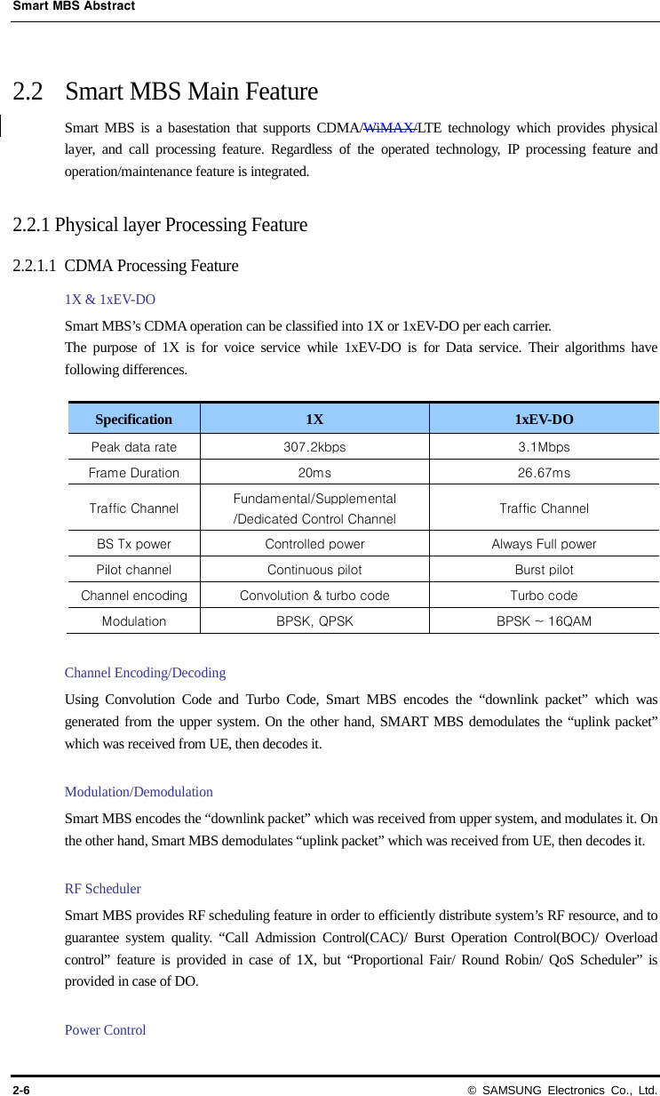
![Smart MBS System Description © SAMSUNG Electronics Co., Ltd. 2-15 Power Input Following is the power specification for Smart MBS. Type Standard Board and Module Input Voltage a) -48 VDC (Voltage Variation Range: -40~-56 VDC) a) UADU(Digital Unit) and RRH(Remote Radio Head) are supplied with -48VDC power from DU cabinet’s rectifier. Rack Dimension and Weight Following is dimension and weight of the Smart MBS. Type Standard Dimension DU(Digital Unit) 434(W) x 385(D) x 88 (H) mm RRH (Remote Radio Head) RRH-C2 : 280(W) x 390(D) x 460(H) mm (Ext. Filter : 268(W) x 75(D) 291(H) mm) RRH-P4 : 227.5(W) x 350(D) x 604(H) mm Weight DU(Digital Unit) Approximately. 12kg RRH (Remote Radio Head) RRH-C2 : 27kg (Ext. Filter 4kg) RRH-P4 : 27kg [Note] Smart MBS’s Outdoor DU cabinet has following dimension and weight. - Dimension : 700(W) × 1035(D) × 1800(H) - Weight : 251kg or less(Except DU) Environmental Requirements Following indicates temperature, humidity, and other environmental requirements where Smart MBS can be operated on. (1) DU (Digital Unit) Type Range Temperature a) 0~50°C(32~122°F) Humidity a) 5~90% Assuming 1kg of air contains water vapor NOT exceeding 0.024 kg. Altitude -60~1,800 m(-197~6,000 ft) Vibration GR-63-CORE Sec.4.4 - Earthquake - Office Vibration - Transportation Vibration Zone 3 Zone 4 (After installing guide rail at the bottom)](https://usermanual.wiki/Samsung-Electronics-Co/SMM-BMR004.User-s-Manual/User-Guide-1804283-Page-37.png)
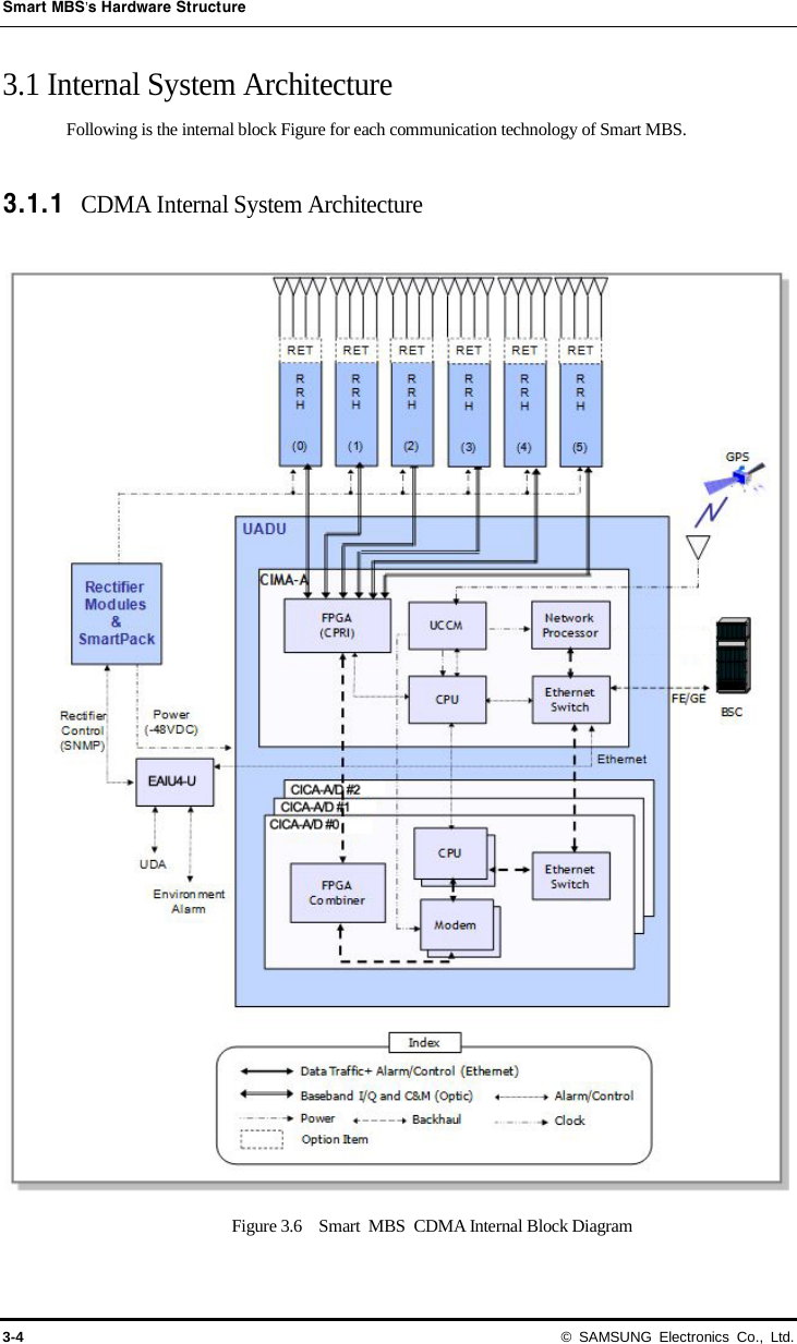
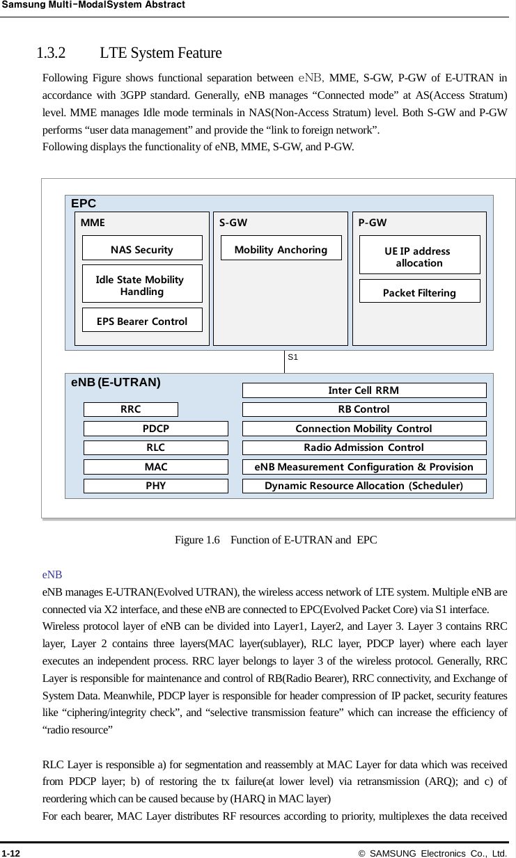
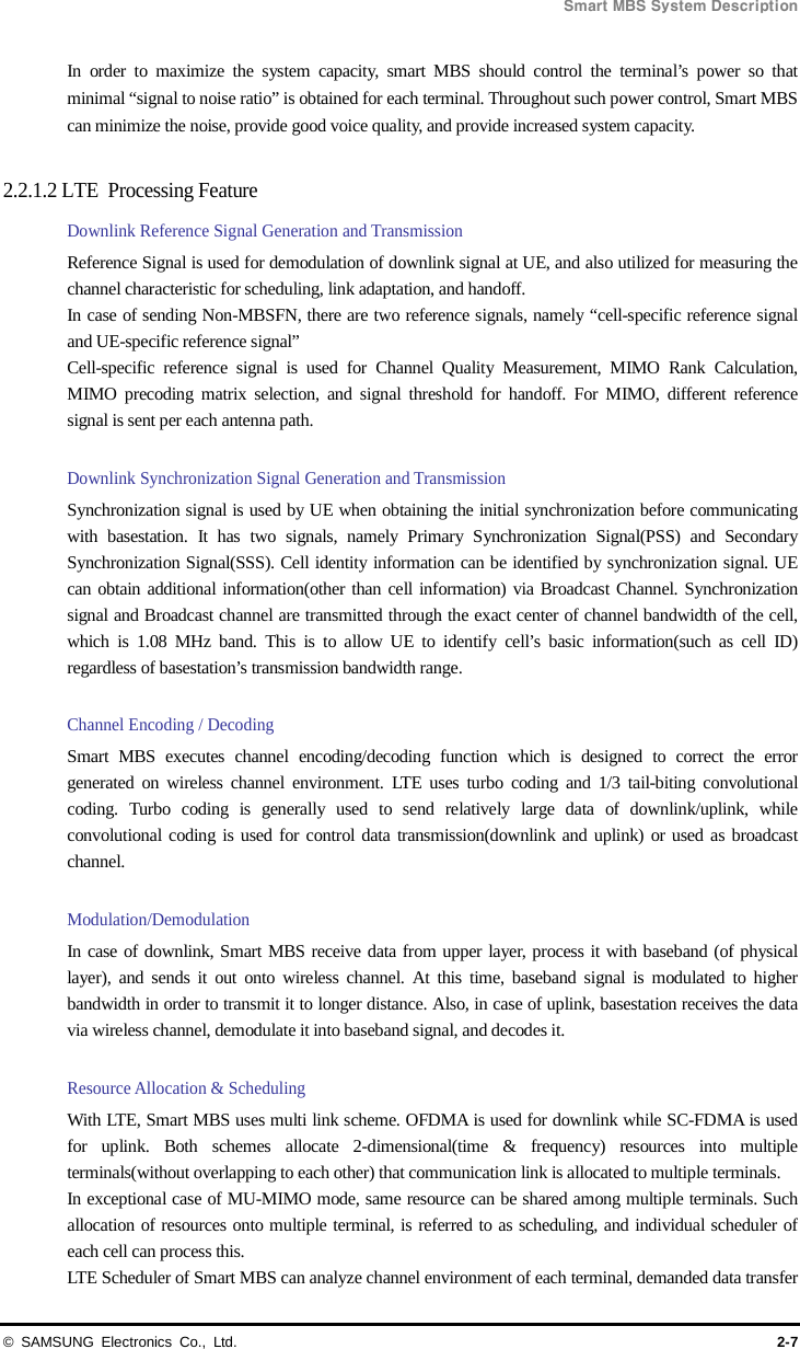
![Smart MBS System Description © SAMSUNG Electronics Co., Ltd. 3-5 A. CDMA Traffic Architecture Transmit path When User Data is received from BSC via Public Network, it goes through Network Synchronization Module, and sent out to CICA via Ethernet Switch of CIMA(Main board). The transmitted data goes through Digital Processing of the Baseband level, then converted to E/O(Electrical to Optic) in form of [Baseband I/Q and C&M interface] which is based on CPRI interface in CIMA. The converted signal is then sent out to remote RRH. RRH converts the received optic signal via O/E(Optic to Electrical) process. The converted broadband baseband signal is then converted to analog signal, and goes through amplifier for amplification. The amplified signal is then filtered through the band pass filter of the operating frequency, and transmitted. Receive Path The RF signal that was transmitted from Antenna is filtered by RRH, and amplified via LNA. This signal then goes through “RF Down-Conversion” and “Digital Down-Conversion” to be converted into baseband signal. This signal is in form of [Baseband I/Q and C&M interface] which is based on CPRI interface, and goes through E/O(Electrical to Optic) conversion once again. The converted signal is then sent to CIMA-A via fiber optic cable, it is converted into Ethernet frame by CDMA baseband signal processor of CICA, and sent to CIMA-A(main board). Finally, it goes through network synchronization module to be sent out to BSC. B. CDMA Clock Architecture UCCM of CIMA-A receives GPS signal from external GPS Antenna, and create the necessary synchronization clock, and distributes it into system’s hardware blocks. When CIMA-A is operated with LTE, CIMA-A provides clock to LTE digital boards. CIMA-A provides 10MHz, PP2S, and SFN(System frame number) to each slot via backboard. CICA and LTE Digital boards use this to generate the required clock. C. CDMA Alarm Architecture CDMA Alarm is based on CIMA-A. CIMA-A collects the alarm from Smart MBS, and reports it to upper layer, and can provide Board Reset. SmartPack collects the outdoor cabinet’s environmental alarm and battery monitoring information, and report to CIMA-A via EAIU4-U. EAIU4-U is mounted inside the Outdoor DU cabinet to synchronize SmartPack, and collect UDA. RRH uses CPRI interface to exchange alarm and control signal with CIMA-A.](https://usermanual.wiki/Samsung-Electronics-Co/SMM-BMR004.User-s-Manual/User-Guide-1804283-Page-47.png)
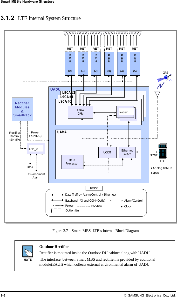
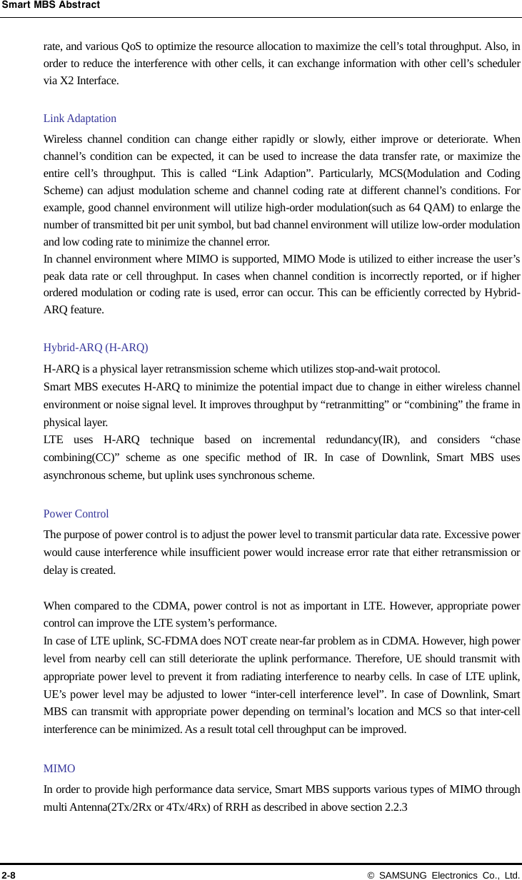
![Smart MBS System Description © SAMSUNG Electronics Co., Ltd. 3-7 A. LTE Traffic Architecture Transmit Path When User Data is received from EPC via Public Network, it goes through Network Synchronization Module, and sent out to L9CA via Ethernet Switch. The transmitted data goes through Digital Processing of the Baseband level, then converted to E/O(Electrical to Optic) in form of [Baseband I/Q and C&M interface] which is based on CPRI interface. The converted signal is then sent out to remote RRH. RRH converts the received optic signal via O/E(Optic to Electrical) process. The converted broadband baseband signal is then converted to analog signal, and goes through amplifier for amplification. The amplified signal is then filtered through the band pass filter of the operating frequency, and transmitted from Antenna. Receive Path The RF signal that was transmitted from Antenna is filtered by RRH, and amplified via LNA. This signal then goes through “RF Down-Conversion” and “Digital Down-Conversion” to be converted into baseband signal. This signal is in form of [Baseband I/Q and C&M interface] which is based on CPRI interface, and goes through E/O(Electrical to Optic) conversion once again. The converted signal is then sent to remote L9CA via fiber optic cable. After the data goes through OFDMA signal processing in L9CA, it is converted into Gigabit Ethernet frame, and sent to EPC via network synchronization module B. LTE Clock Architecture UCCM of UAMA receives reference signal from external GPS Antenna, and generate PP2S, Digital 10 MHz, SFN(System Frame Number), and distribute them into L9CA in the system. L9CA then receives PP2s, Digital 10 MHz clock. It should use its own PLL to generate system clock (30.72MHz), CPRI Reference Clock(122.88MHz), and 10msec clock to distribute it to RRH. At synchronization of UADU and RRH, RRH receives the necessary system clock and sync clock that are required for CPRI interface, from L9CA. If LTE system is mounted DU Shelf identical to CDMA, it is supplied the clock for operation from CIMA-A C. LTE Alarm Architecture LTE Alarm is based on UAMA. UAMA collects the alarm from Smart MBS, and reports it to upper layer, and can provide Board Reset. SmartPack collects the outdoor cabinet’s environmental alarm and battery monitoring information, and report to UAMA via EAIU4-U. EAIU4-U is mounted inside the Outdoor DU cabinet to synchronize with SmartPack, and collect UDA. RRH uses CPRI interface to exchange alarm and control signal with UAMA.](https://usermanual.wiki/Samsung-Electronics-Co/SMM-BMR004.User-s-Manual/User-Guide-1804283-Page-49.png)