Samsung Electronics Co SMM-BMR004 Remote Radio Head User Manual
Samsung Electronics Co Ltd Remote Radio Head
UserManual.wiki
>
Samsung Electronics Co
>
SMM-BMR004 User Manual
>
User Manual
Contents
1.
User's Manual
2.
User Manual
User Manual
Navigation menu
Upload a User Manual
Namespaces
Wiki Guide
HTML
PDF
Info
Views
User Manual
Discussion / Help
Navigation

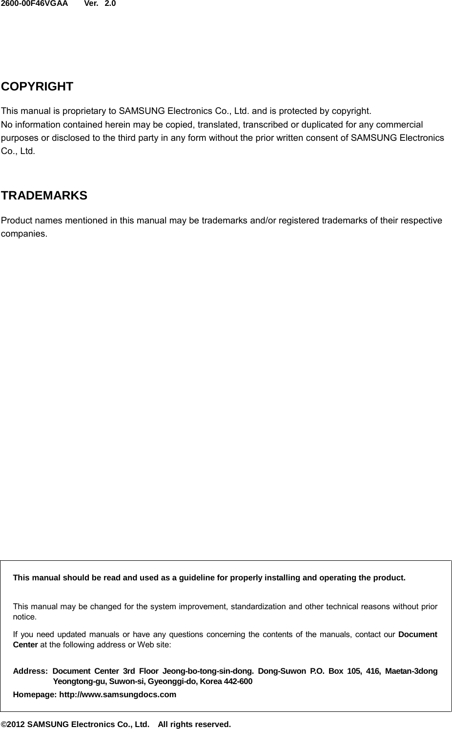

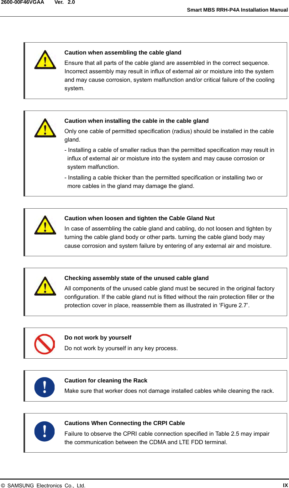
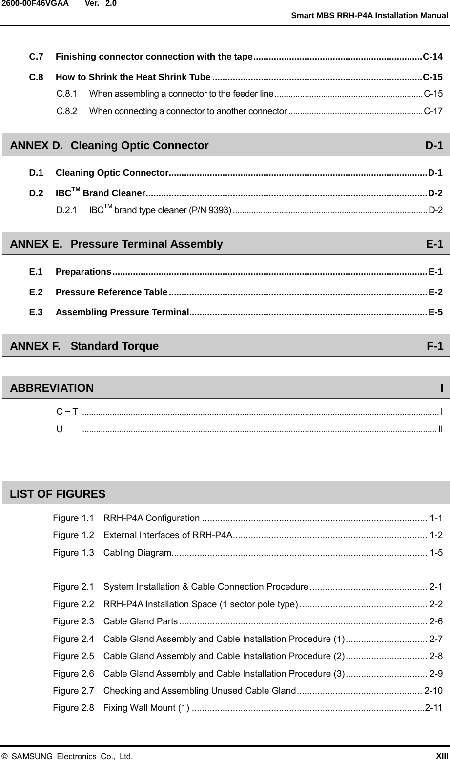
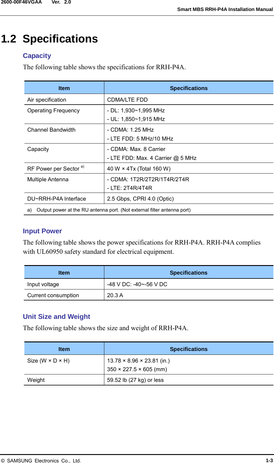
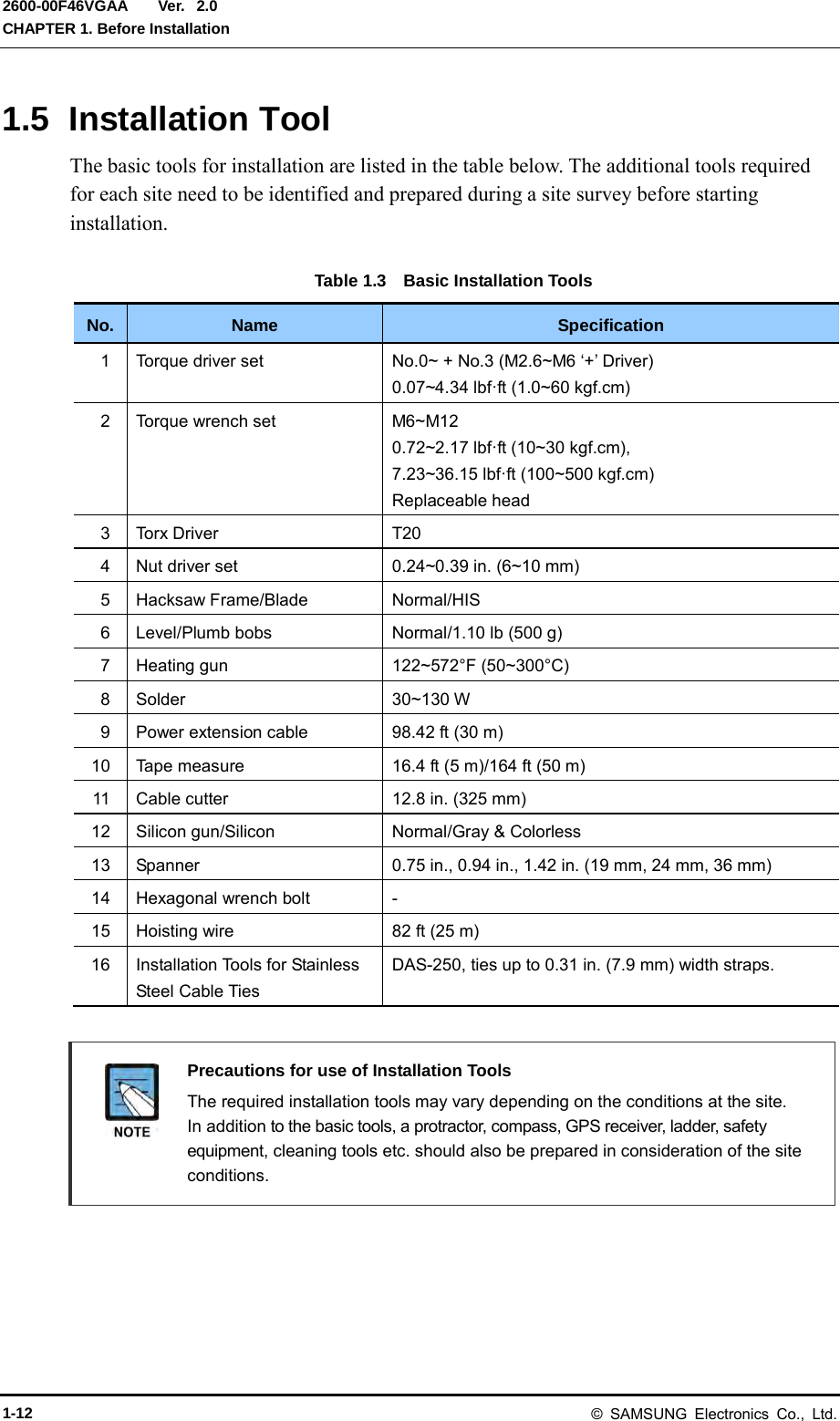
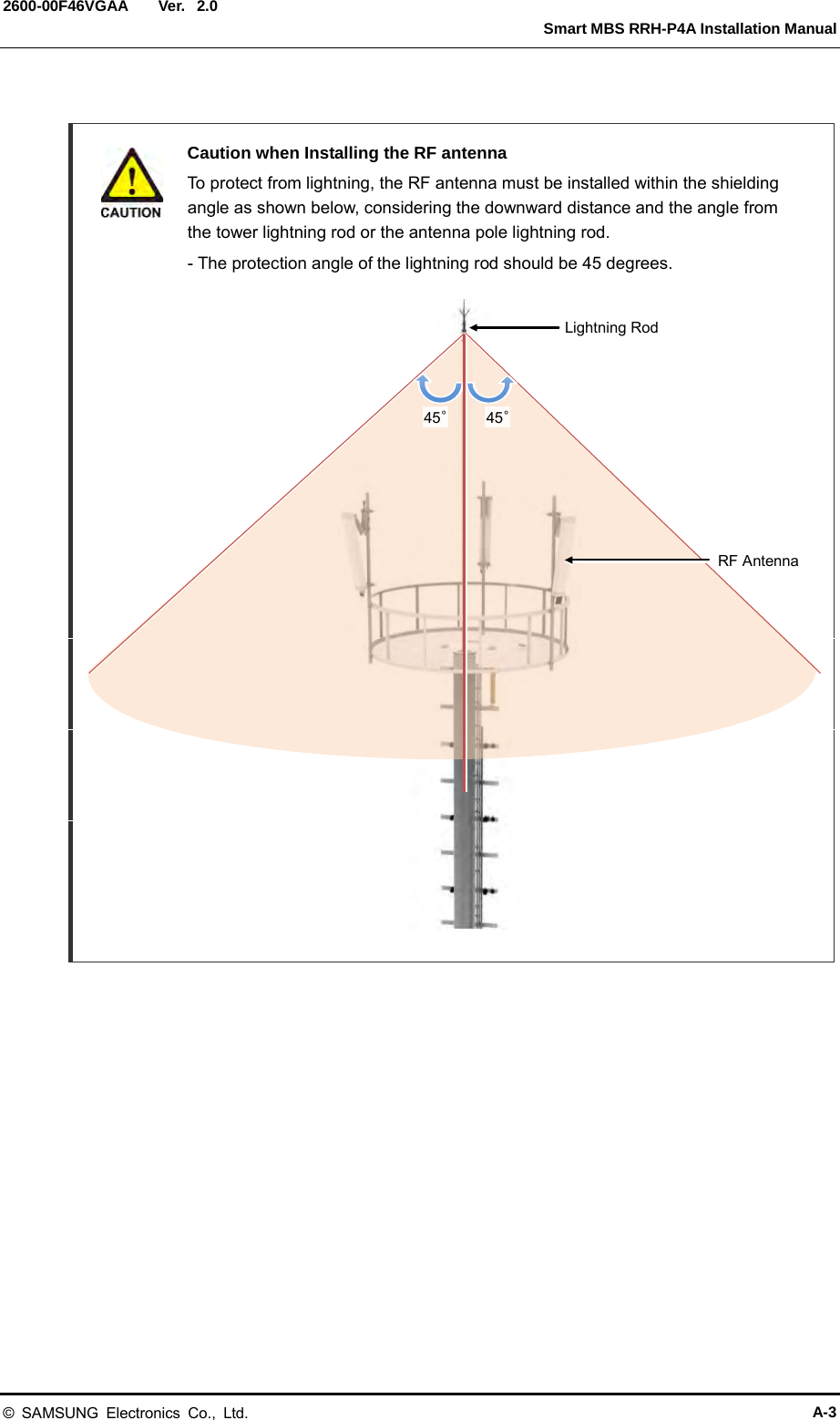
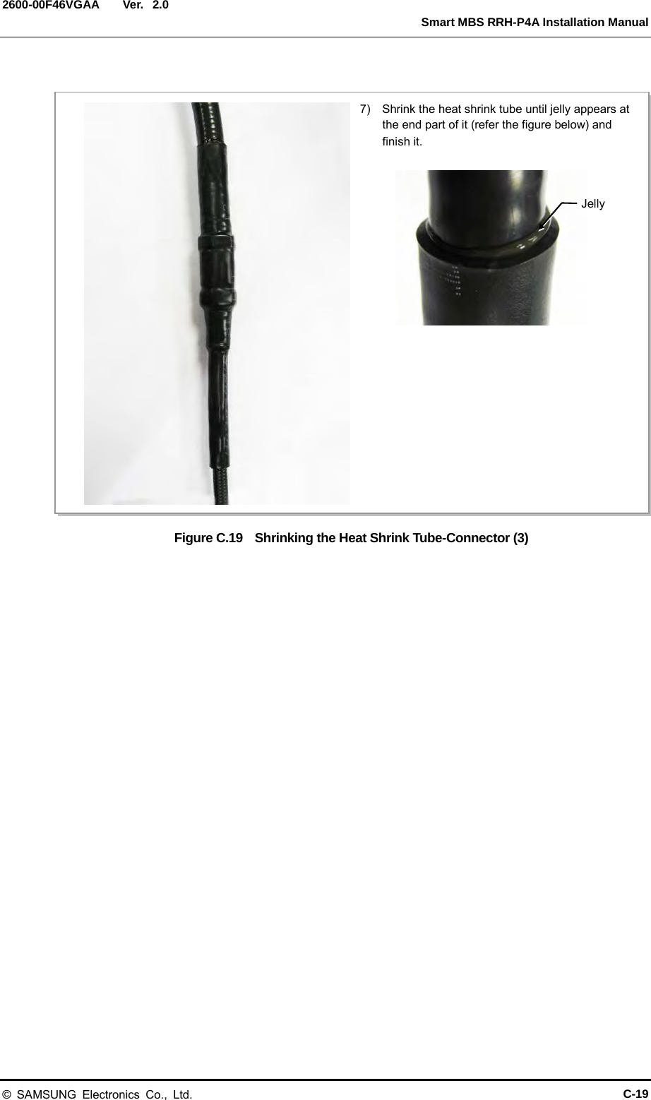
![Ver. Smart MBS RRH-P4A Installation Manual 2600-00F46VGAA 2.0 CHAPTER 1. Before Installation 1.1 System Configuration RRH-P4A Configuration The following shows the configuration of RRH-P4A. Figure 1.1 RRH-P4A Configuration [Top View] [Front View] [Bottom View] [Right View] [Left View] [Rear View] 23.81 (605) 8.96 (227.5) 13.78 (350) Unit: in. (mm) © SAMSUNG Electronics Co., Ltd. 1-1](https://usermanual.wiki/Samsung-Electronics-Co/SMM-BMR004.User-Manual/User-Guide-1983926-Page-19.png)
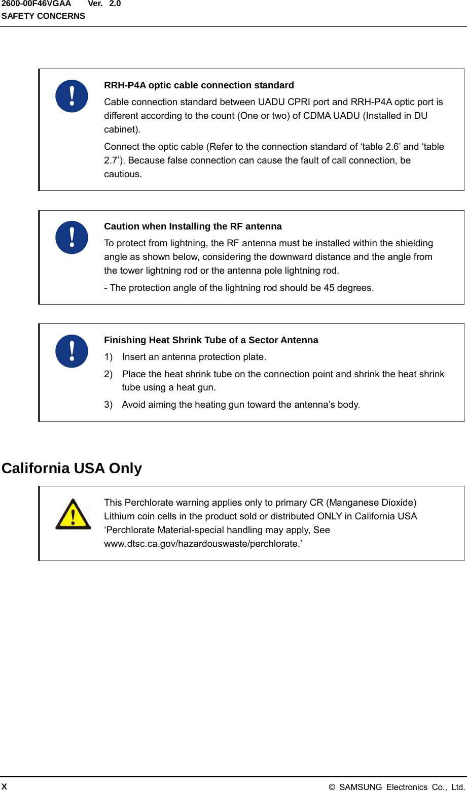
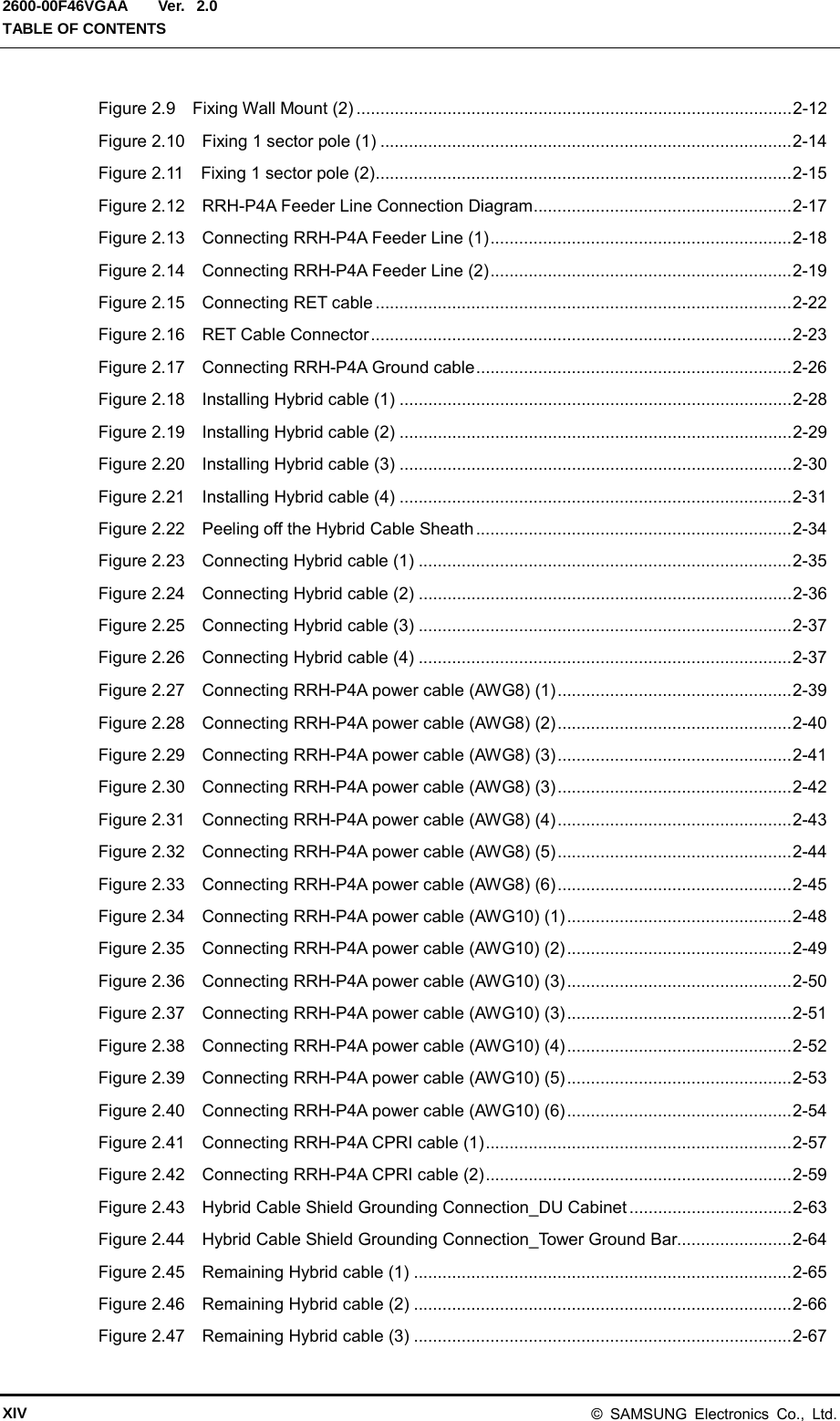
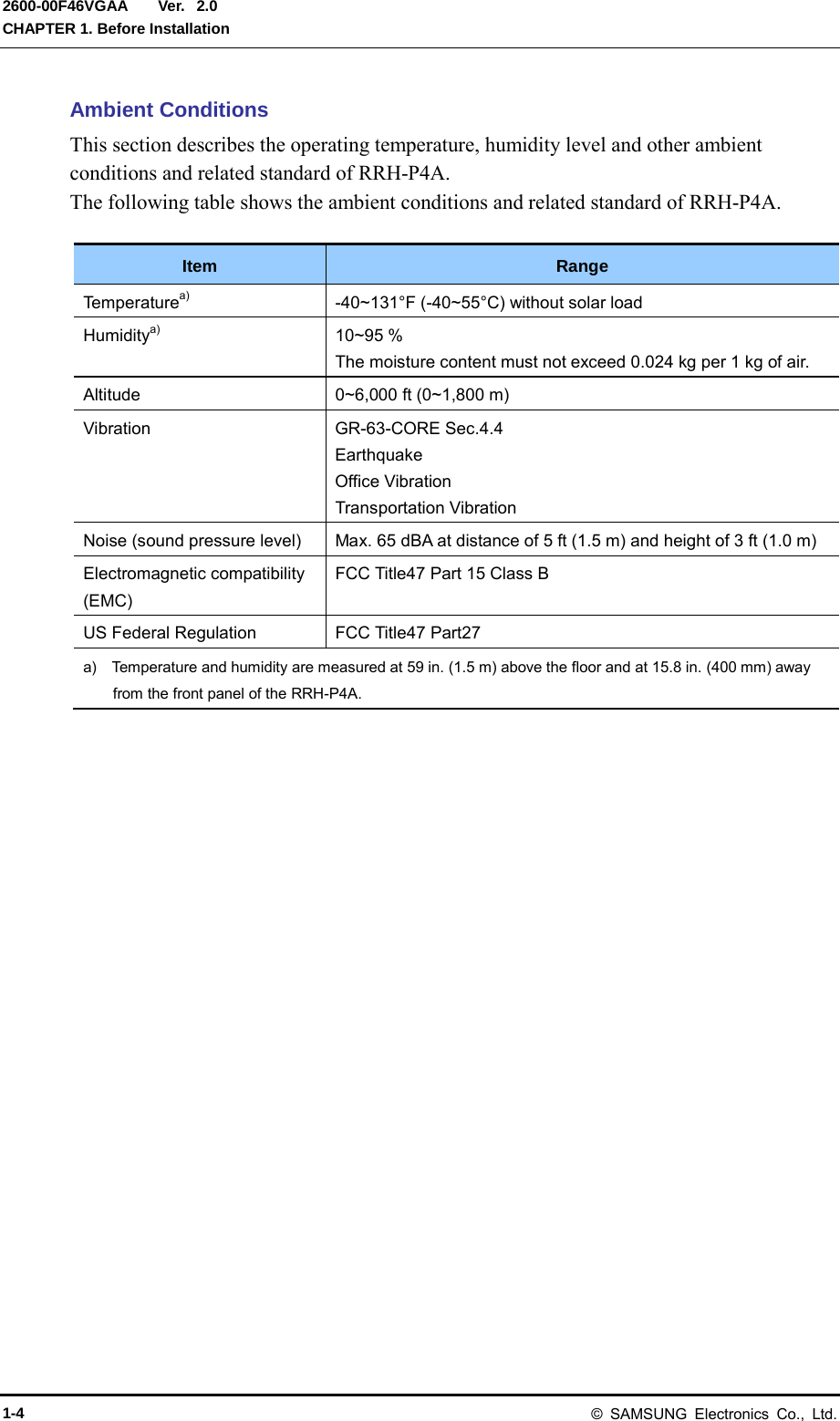
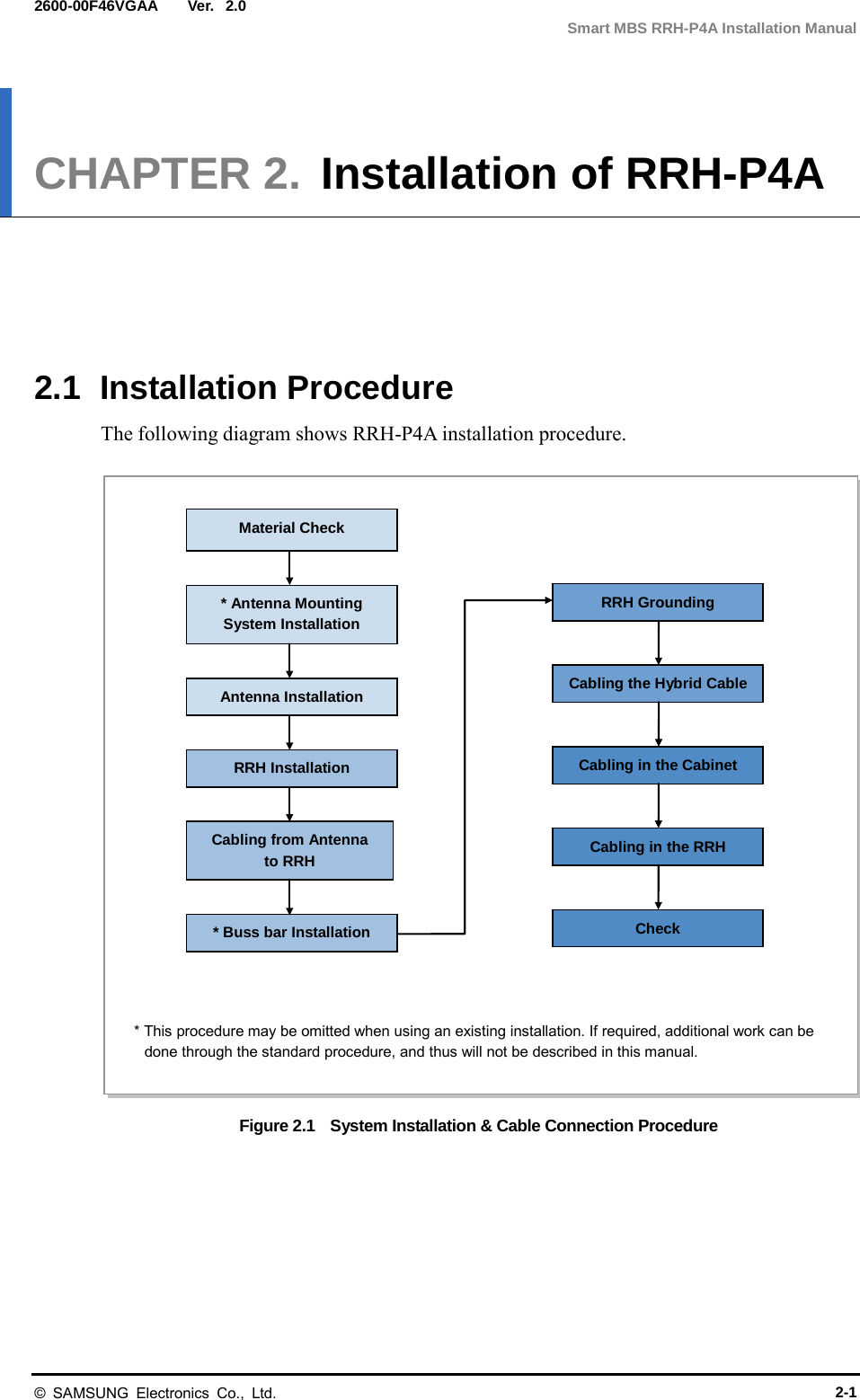
![Ver. CHAPTER 1. Before Installation 2600-00F46VGAA 2.0 External Interfaces of RRH-P4A The following shows the external interfaces of RRH-P4A. Figure 1.2 External Interfaces of RRH-P4A [Bottom View] POWER [-48 V] ANT 3 OPTIC RET Ground ANT 2 ANT 1 ANT 0 1-2 © SAMSUNG Electronics Co., Ltd.](https://usermanual.wiki/Samsung-Electronics-Co/SMM-BMR004.User-Manual/User-Guide-1983926-Page-20.png)
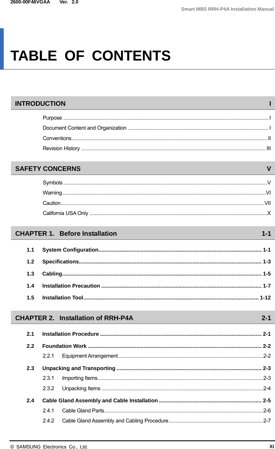
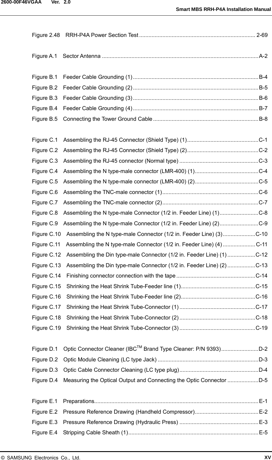
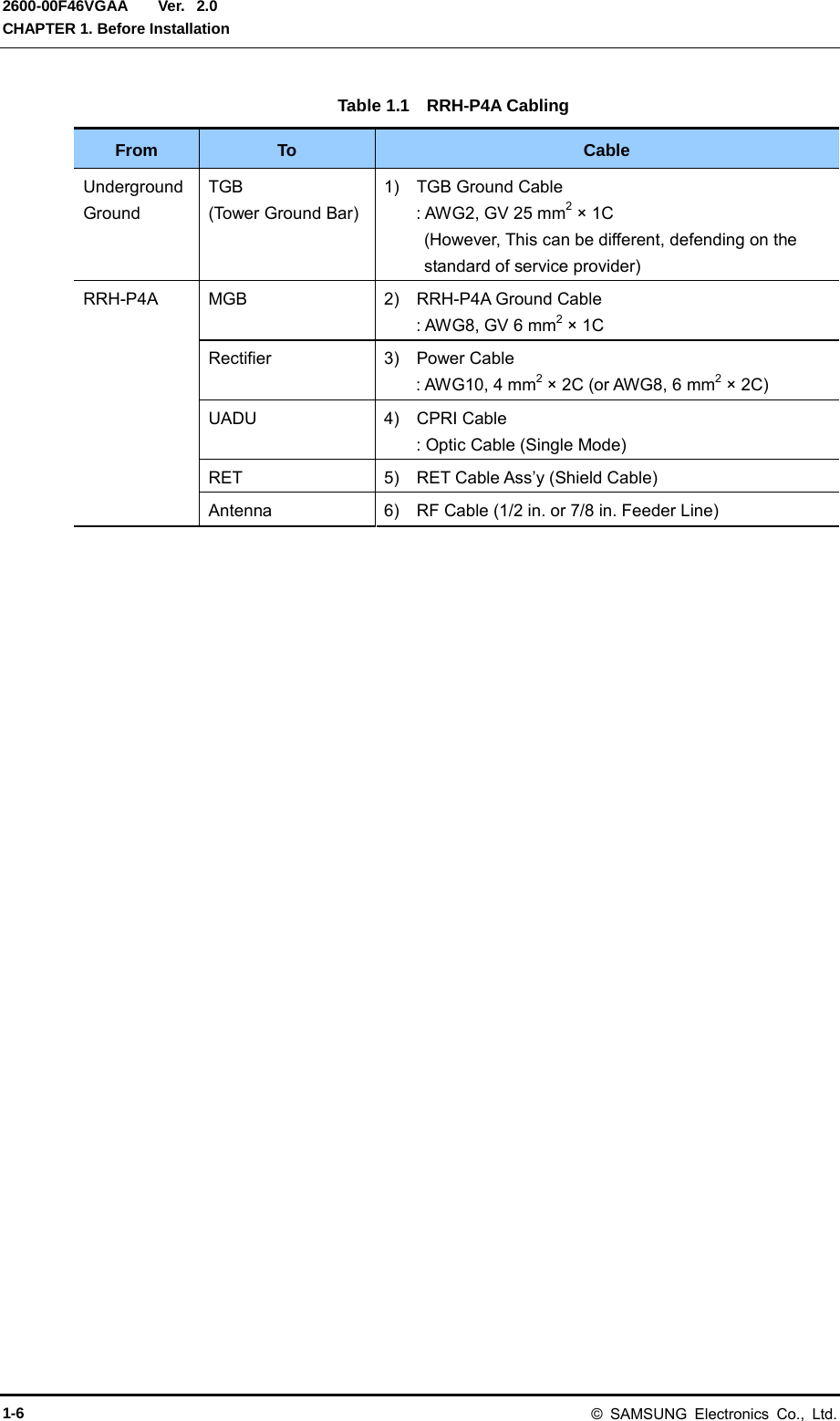
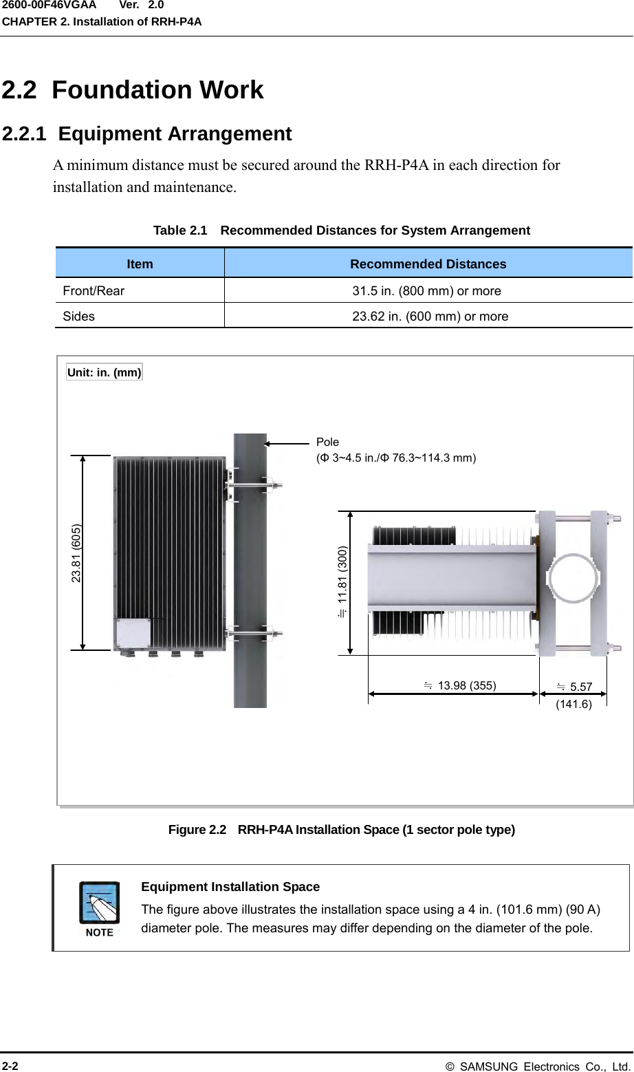
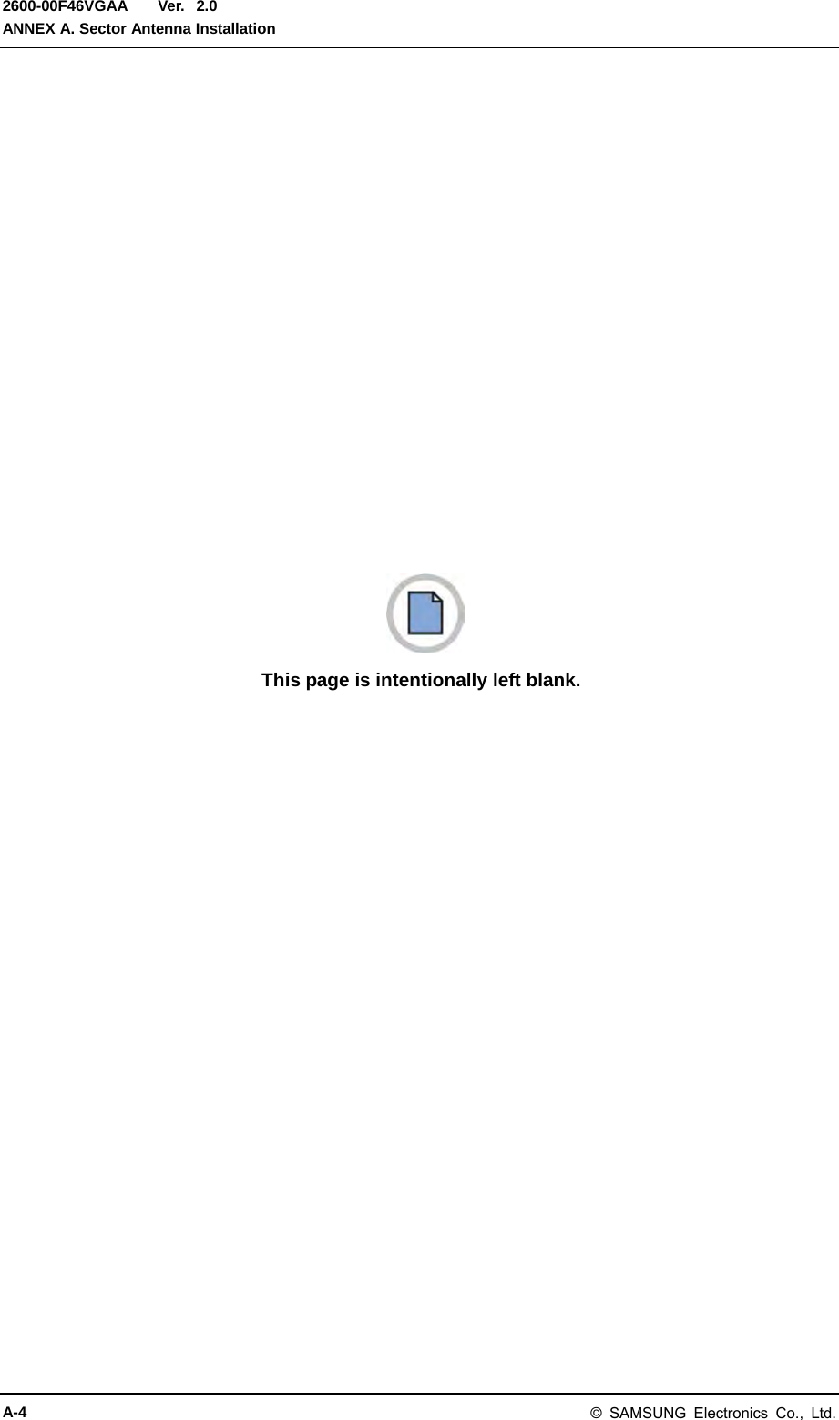
![Ver. Smart MBS RRH-P4A Installation Manual 2600-00F46VGAA 2.0 1.3 Cabling The following shows the cables connected to RRH-P4A. Figure 1.3 Cabling Diagram [RF Antenna] 1) TGB Ground Cable [TGB] Feeder Line Ground Cable (Ground Kit/7/8 in. Feeder Line or more) ※ TGB and Ground Kit are used in case of the 7/8 in. feeder line or more. [Rectifier] [UADU] 3) Power Cable 4) CPRI Cable 5) RET Cable 6) RF Cable 2) RRH-P4A Ground Cable © SAMSUNG Electronics Co., Ltd. 1-5](https://usermanual.wiki/Samsung-Electronics-Co/SMM-BMR004.User-Manual/User-Guide-1983926-Page-23.png)
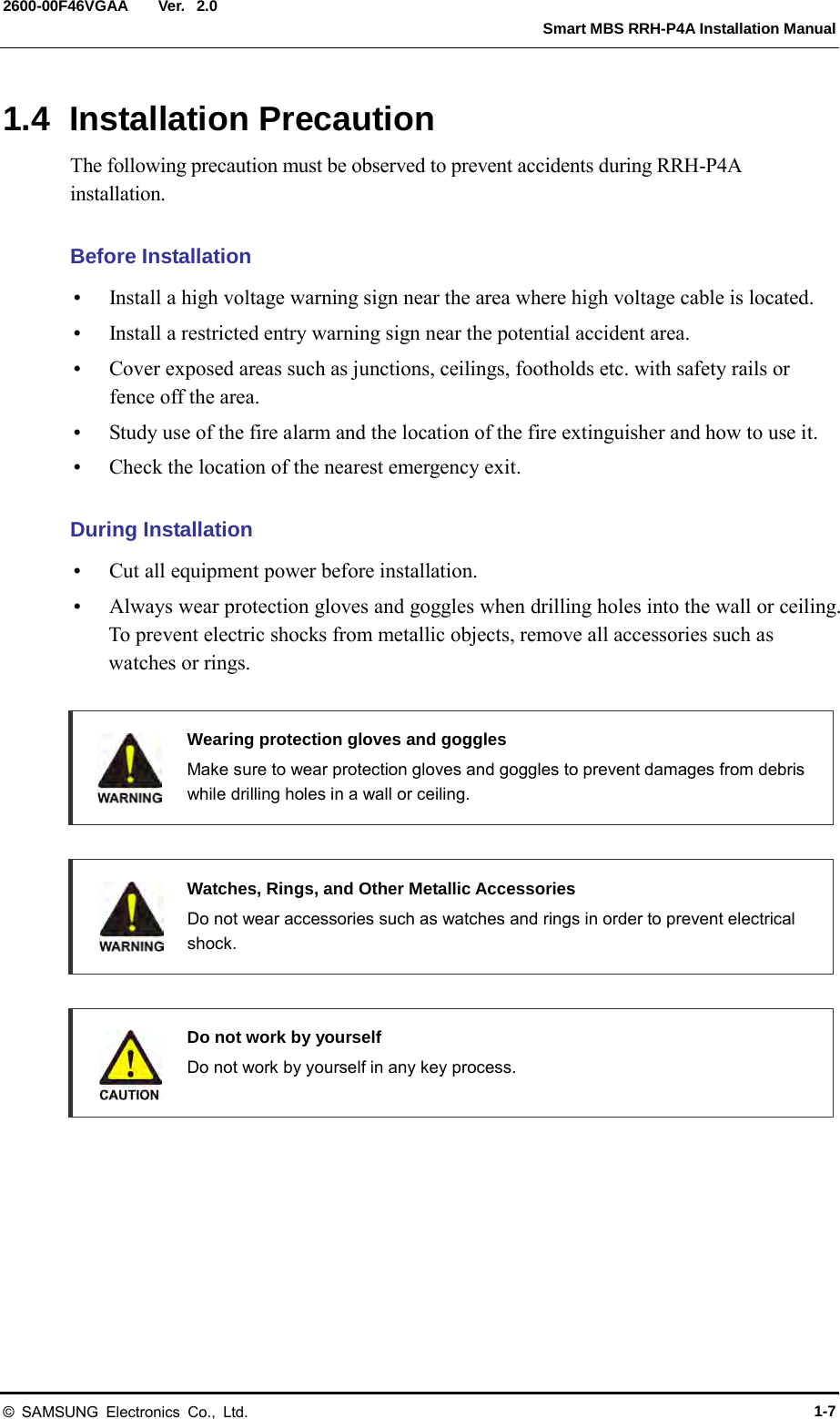
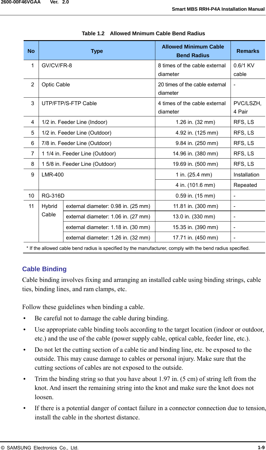
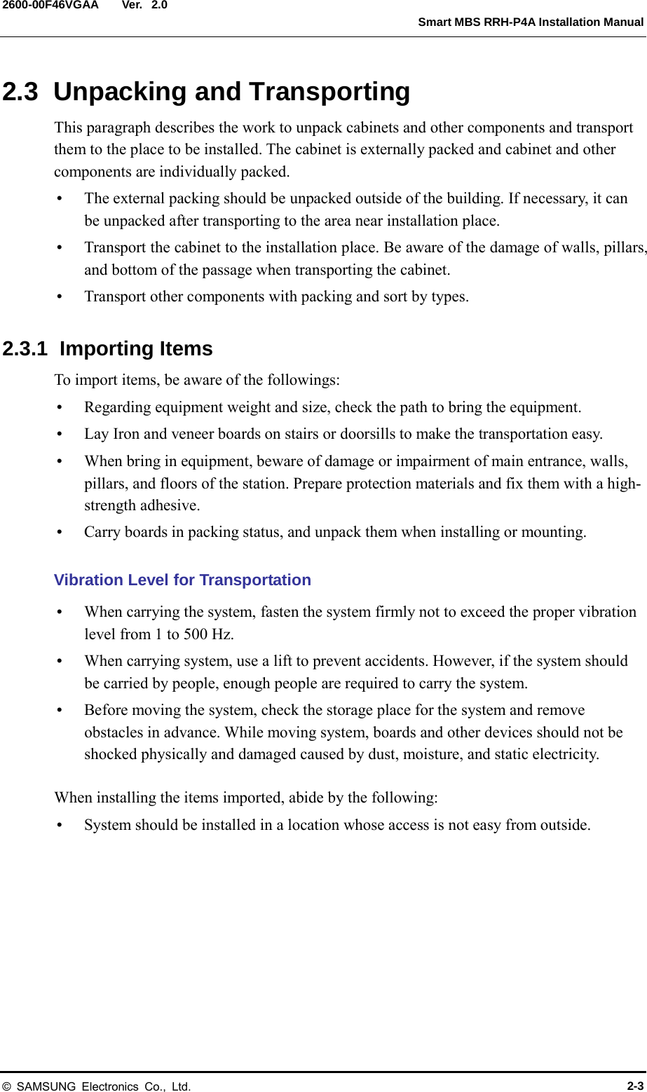
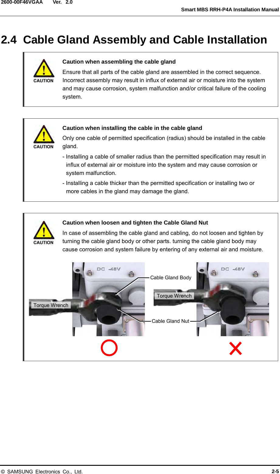
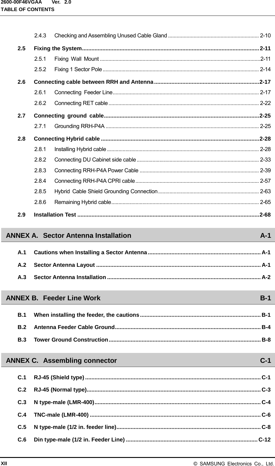
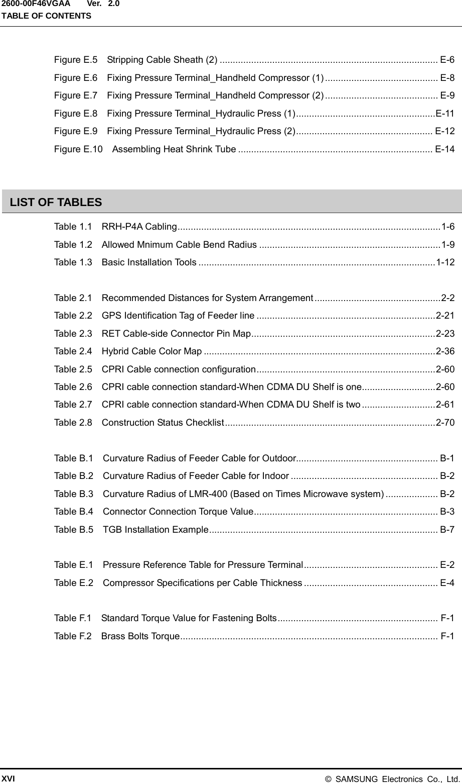
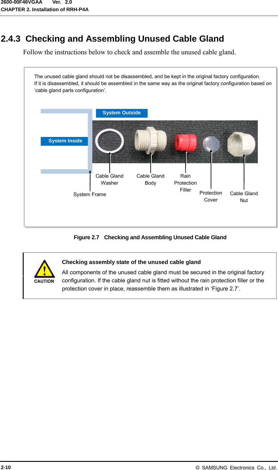
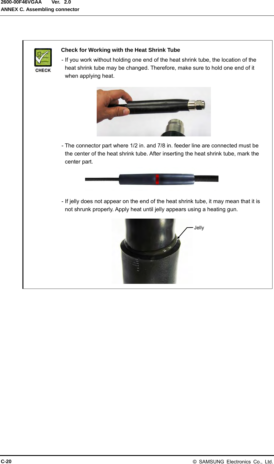
![Ver. Smart MBS RRH-P4A Installation Manual 2600-00F46VGAA 2.0 2.4.2 Cable Gland Assembly and Cabling Procedure Follow the cable gland assembly instructions below to prevent influx of moisture and foreign substances. Figure 2.4 Cable Gland Assembly and Cable Installation Procedure (1) 1) Check the cable gland built on the unit whether it has the protection cover inside the cable gland nut as shown in the picture below (cross-section picture of outer wall of the unit), the same as the original factory configuration. 3) Remove the protection cover (circular transparent plate) and keep it separately. [Cross-section] Protection Cover Cable Gland Nut 2) Separate the cable gland nut by loosening counterclockwise. Here, check the protection cover (circular transparent plate). Protection Cover Cable Gland Nut [Loosened Cable Gland Nut] Protection Cover [Removed Protection Cover] © SAMSUNG Electronics Co., Ltd. 2-7](https://usermanual.wiki/Samsung-Electronics-Co/SMM-BMR004.User-Manual/User-Guide-1983926-Page-37.png)
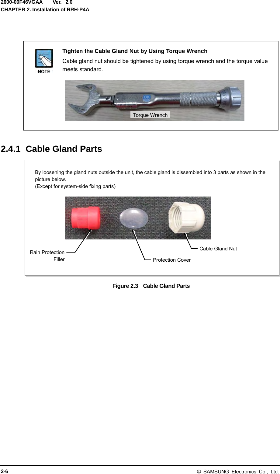
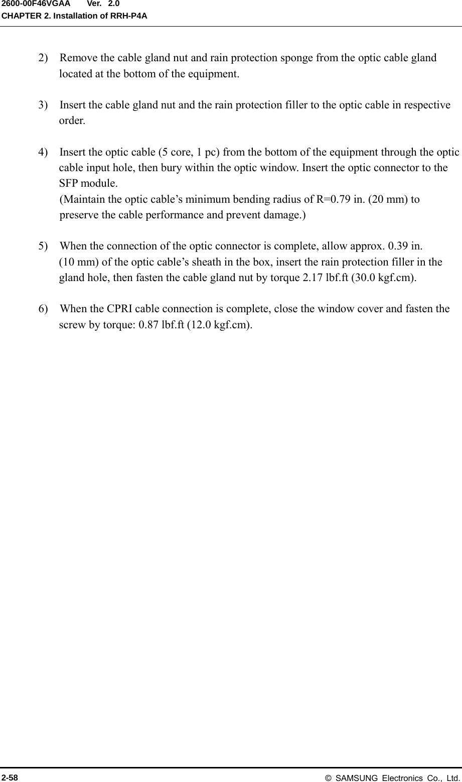
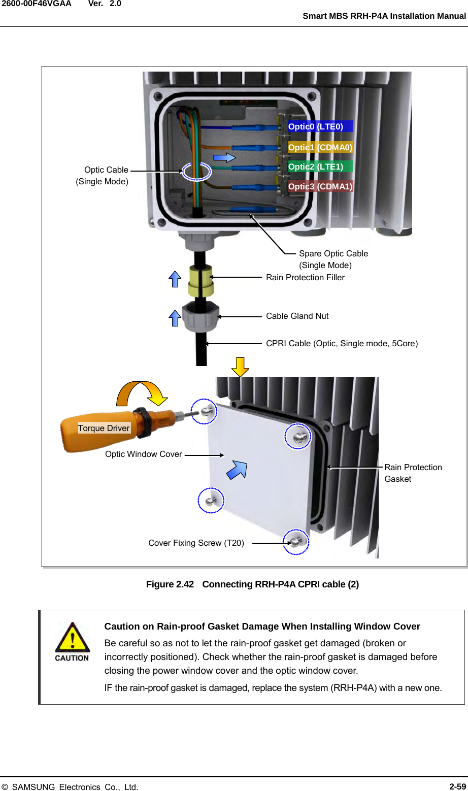
![Ver. CHAPTER 2. Installation of RRH-P4A 2600-00F46VGAA 2.0 Figure 2.5 Cable Gland Assembly and Cable Installation Procedure (2) Inside Outside 4) Separate the rain protection filler from the cable gland body. 6) After installing the cable through the cable gland body, connect it to the system according to assembling standard and clean up the rest of the cable. 5) Install the cable by passing it through the cable gland nut from outside to inside. Rain Protection Filler [Separated rain protection filler] Cable Gland Nut Cable Inside Outside 7) Put the rain protection filler on the cable inside the cable gland nut. At this time, widen the split groove of rain protection filler and wrap the cable around. Rain Protection Filler Cable Cable Gland Nut Split groove of Rain Protection Filler 2-8 © SAMSUNG Electronics Co., Ltd.](https://usermanual.wiki/Samsung-Electronics-Co/SMM-BMR004.User-Manual/User-Guide-1983926-Page-38.png)
![Ver. CHAPTER 2. Installation of RRH-P4A 2600-00F46VGAA 2.0 Mounting Protection Cap on RRH-P4A Output Port Make sure to mount a protection cap on the output ports (ANT 0-3) when you putting up or down the RRH-P4A. If you use the RRH-P4A without mounting a protection cap, it may cause damage to or scratches on the output port and affect the output performance of the RRH-P4A. How to lift up RRH-P4A After fixing the bracket of RRH-P4A side, bind the rope to the heat sink of RRH-P4A and a space between top bracket and RRH-P4A, lift up using a hoist lift as shown below. For the safety, maintain the status of lifting up by completing RRH-P4A installation. Unbind the rope after the installation is complete. Rope Hoist Line RRH-P4A Top Bracket Protection Cap Not Mounted [Good: Protection Cap Mounted] [Bad: Protection Cap Not Mounted] 2-16 © SAMSUNG Electronics Co., Ltd.](https://usermanual.wiki/Samsung-Electronics-Co/SMM-BMR004.User-Manual/User-Guide-1983926-Page-46.png)
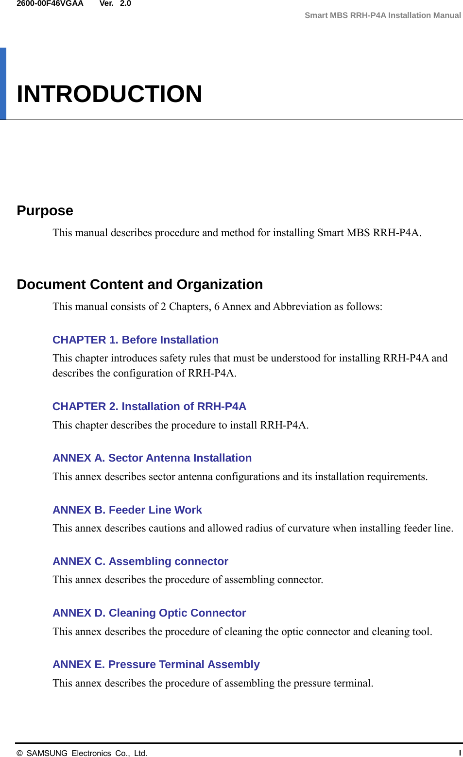
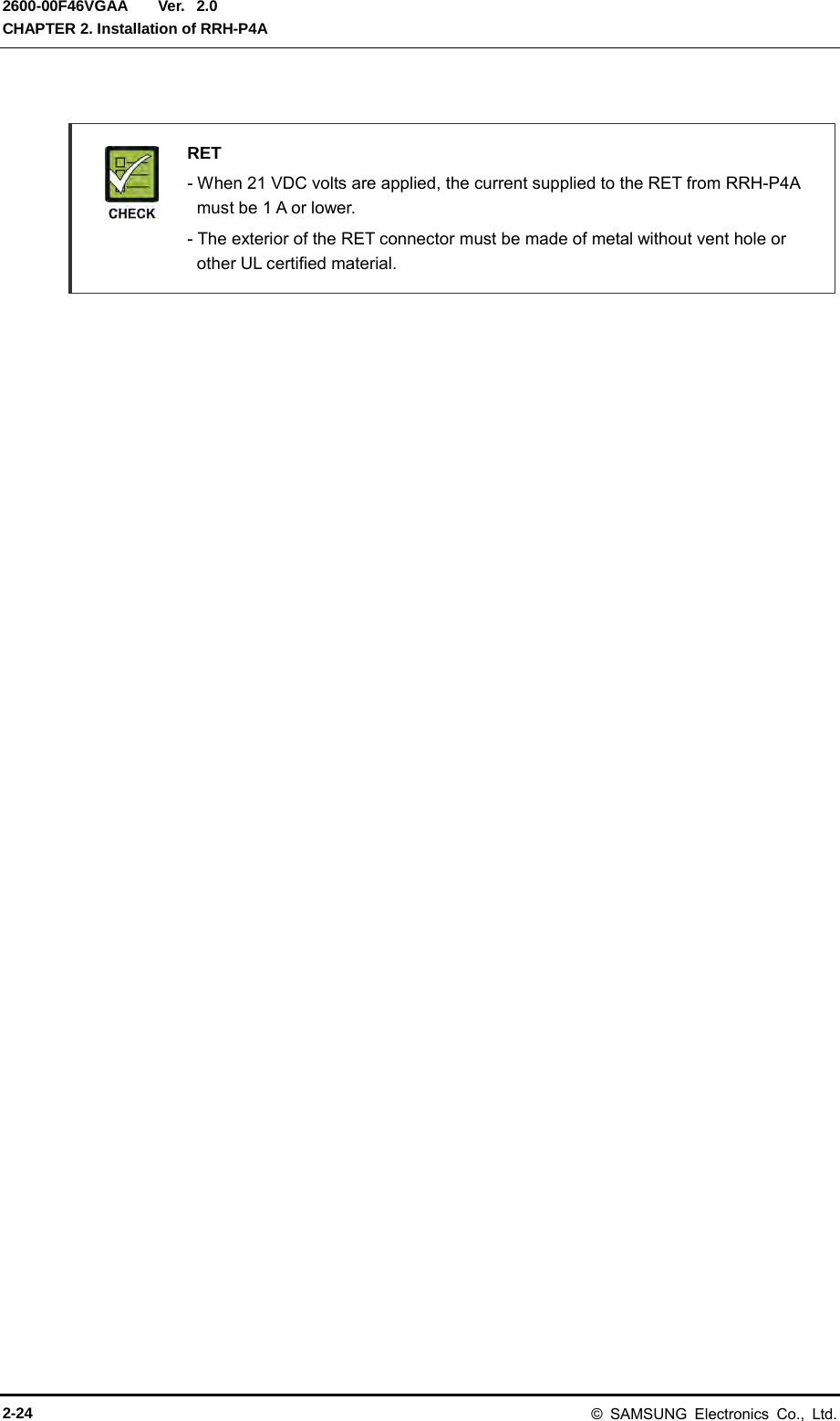
![Ver. Smart MBS RRH-P4A Installation Manual 2600-00F46VGAA 2.0 Figure 2.16 RET Cable Connector Table 2.3 RET Cable-side Connector Pin Map Amphenol AISG Connector Male Function Female 1 +12 V Optional (N.C) 1 2 N.C 2 3 RS485 B 3 4 RS485 GND 4 5 RS485 A 5 6 +21 V 6 7 +21 V RTN 7 8 N.C 8 Caution When Connecting RET Cable Make sure to turn off the breaker connected to the RRH-P4A power of the DU cabinet before connecting the RET cable between the antenna RET port and the RRH-P4A RET port. If you connect or disconnect the RET cable while the breaker is turned on, it may cause an electric short circuit resulting in damage to the RET function. [RRH-P4A-side Connector: AISG Male] [Antenna-side Connector: AISG Female] 1 6 8 4 2 5 3 7 8 6 1 4 2 7 3 5 © SAMSUNG Electronics Co., Ltd. 2-23](https://usermanual.wiki/Samsung-Electronics-Co/SMM-BMR004.User-Manual/User-Guide-1983926-Page-53.png)
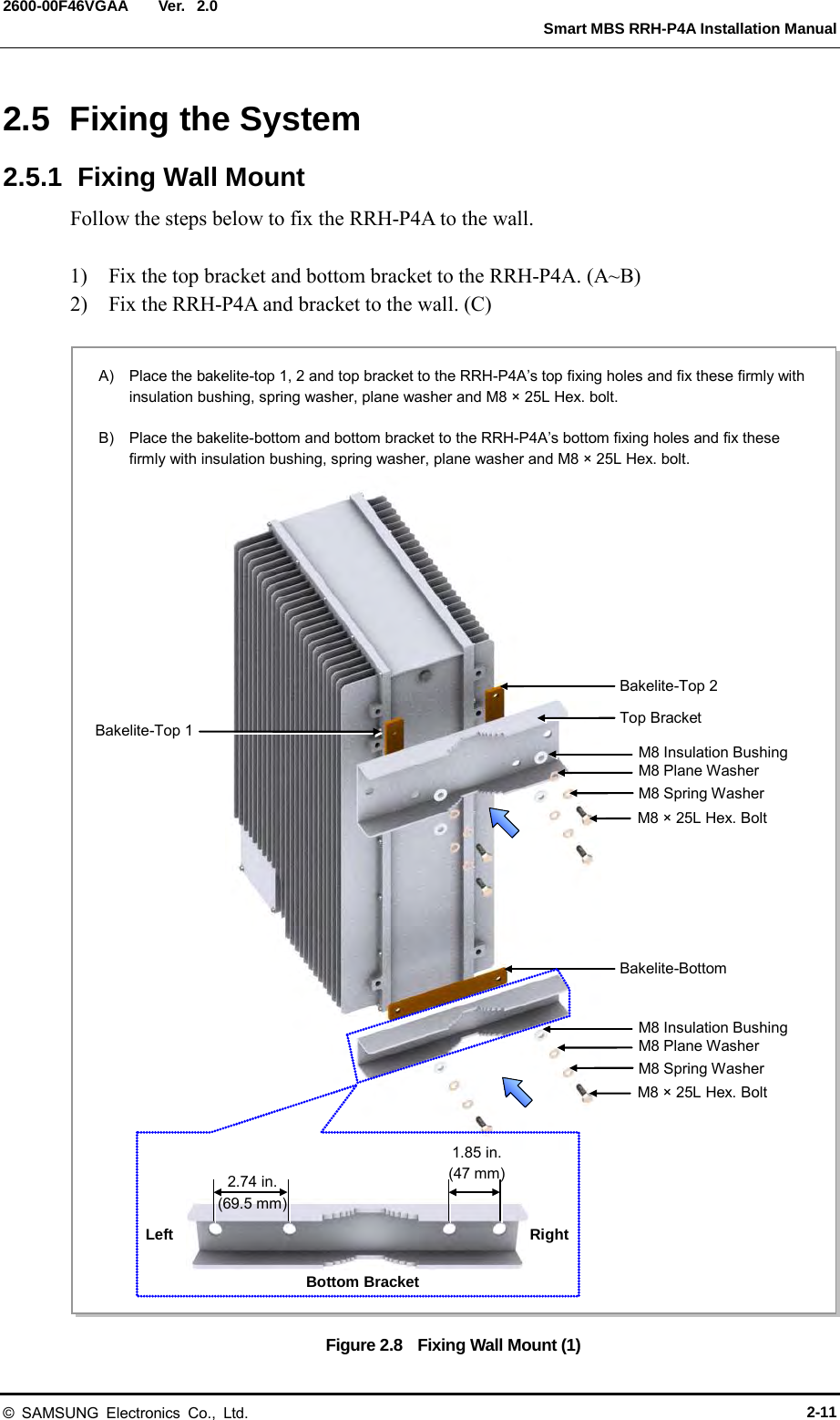
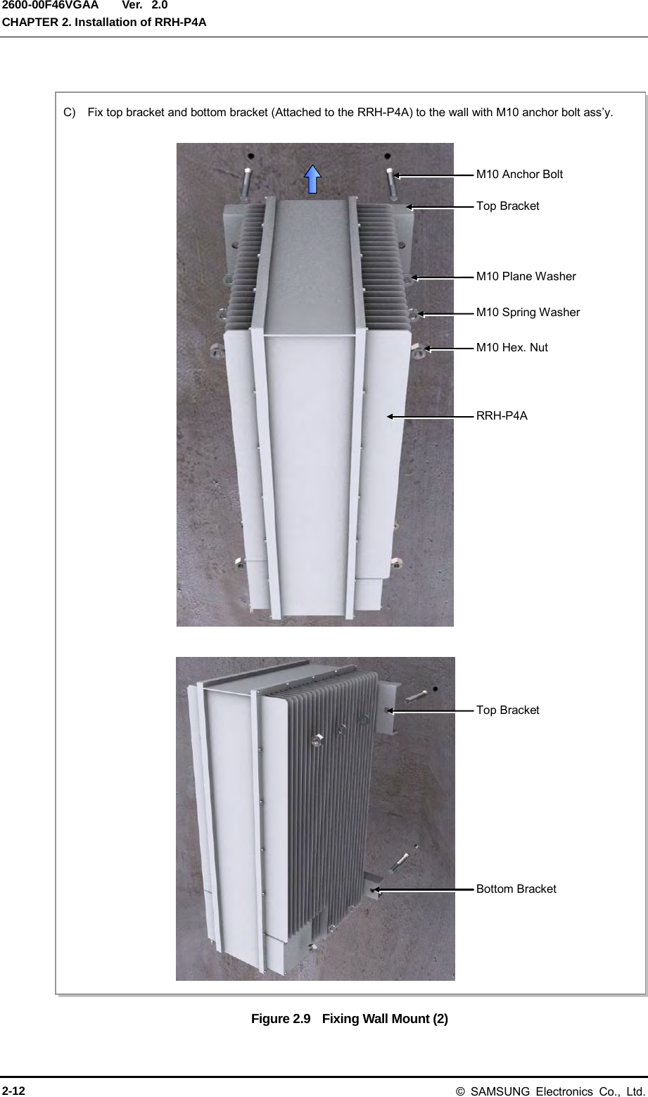
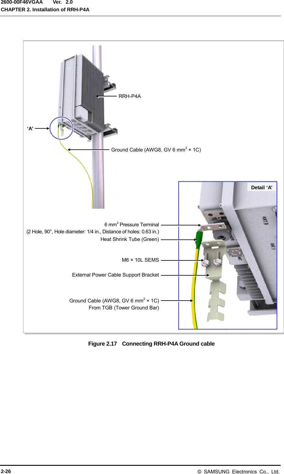
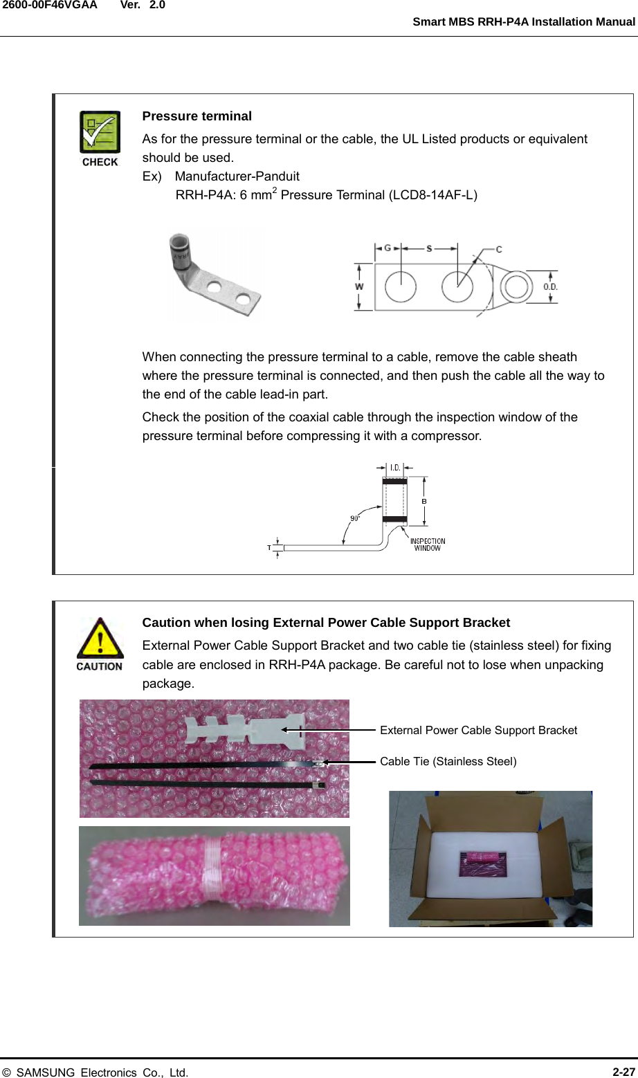
![Ver. Smart MBS RRH-P4A Installation Manual 2600-00F46VGAA 2.0 2.7 Connecting ground cable 2.7.1 Grounding RRH-P4A Follow the steps below to connect the RRH-P4A ground cable. 1) Install one ground cable (AWG8, GV 6 mm2 × 1 C) from TGB to the ground terminal at the bottom of RRH-P4A. 2) Install the pressure terminal and the heat shrink tube at the end of the cable. - Pressure terminal: GV 6 mm2, 2 hole, 90°, hole diameter: 1.4 in. (6.3 mm), distance of holes: 0.63 in. (16 mm) 3) Place the pressure terminal at one end of the ground cable of RRH-P4A aligning with the fixing holes and fix it using M6 SEMS. [When being tighten by screw, apply 2.76~3.37 lbf.ft (38.16~46.64 kgf.cm torque.)] © SAMSUNG Electronics Co., Ltd. 2-25](https://usermanual.wiki/Samsung-Electronics-Co/SMM-BMR004.User-Manual/User-Guide-1983926-Page-55.png)
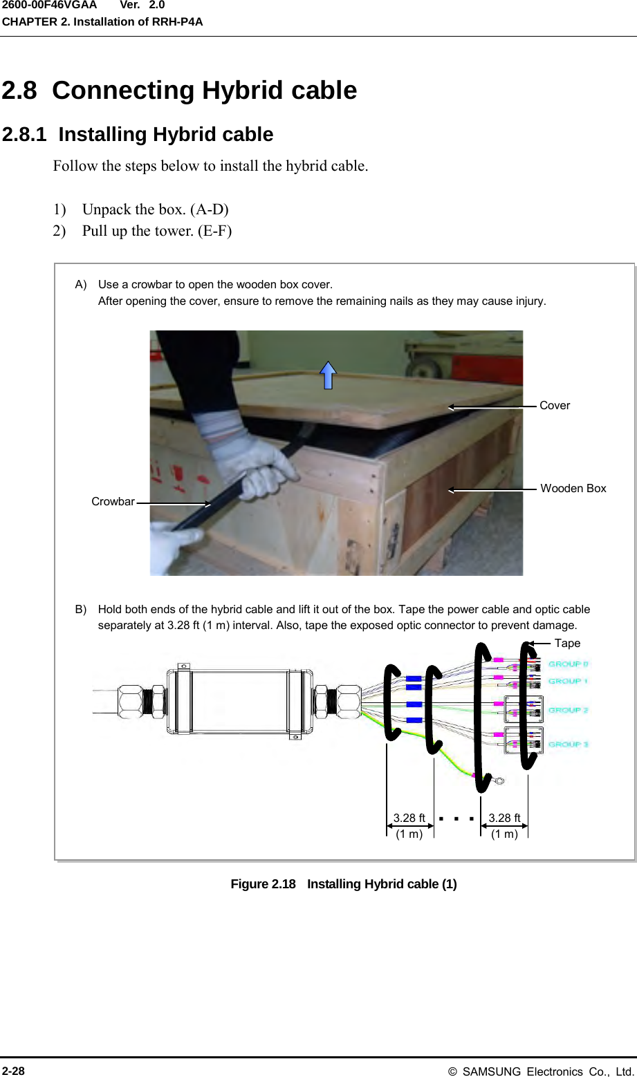
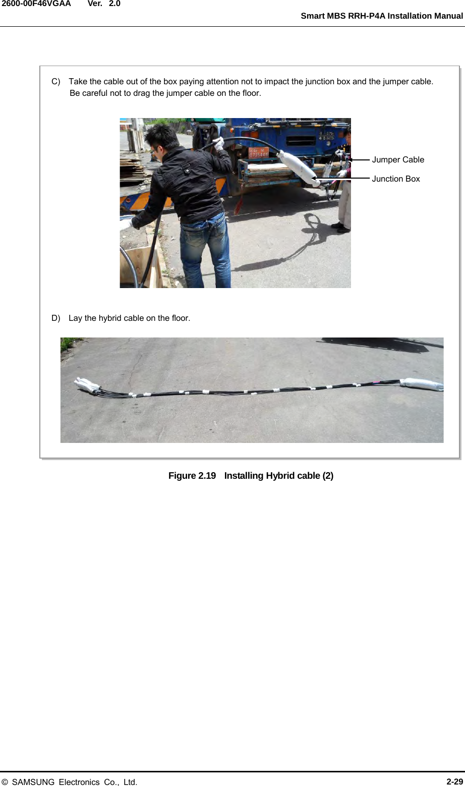
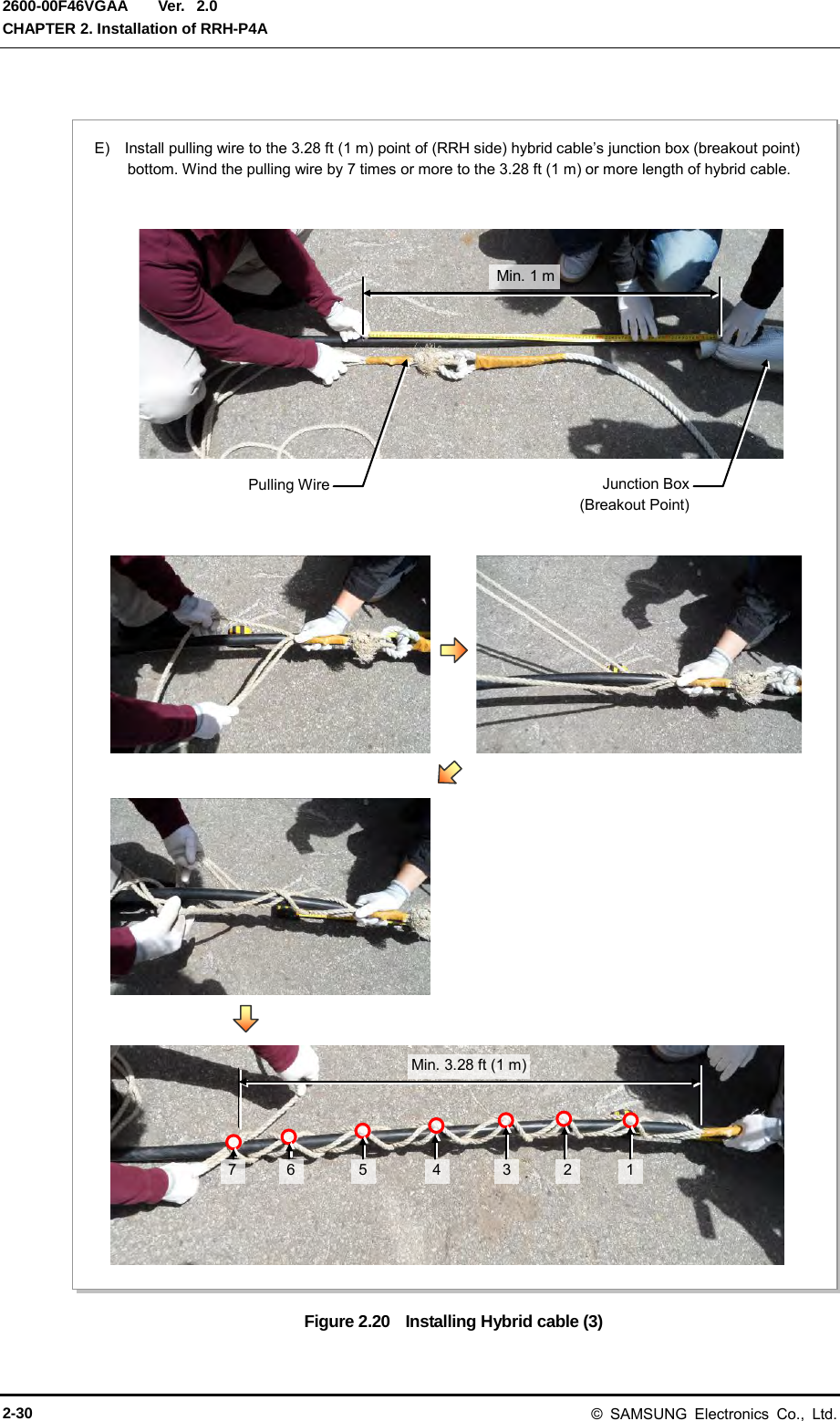
![Ver. Smart MBS RRH-P4A Installation Manual 2600-00F46VGAA 2.0 Figure 2.21 Installing Hybrid cable (4) F) Fix the cable to the hoisting wire with a cable tie at regular intervals [within 3.28 ft (1 m)] to prevent impact or tension to the upper side of the junction box when lifting the hoist. Maintain hoisting wire in a straight line, separate the RRH-side cable’s curve from the hoisting wire with 5.9 in. (150 mm) or more distance. And fix cable and wire with cable tie. (When lifting the hoist, be careful not to apply tension to other areas of the hybrid cable except where the pulling wire is attached.) Max. 3.28 ft (1 m) Junction Box (Breakout Point) Pulling Wire Hoisting Wire Max. 3.28 ft (1 m) Max. 3.28 ft (1 m) Hoisting Wire Hybrid Cable More than 5.9 in. (150 mm) © SAMSUNG Electronics Co., Ltd. 2-31](https://usermanual.wiki/Samsung-Electronics-Co/SMM-BMR004.User-Manual/User-Guide-1983926-Page-61.png)
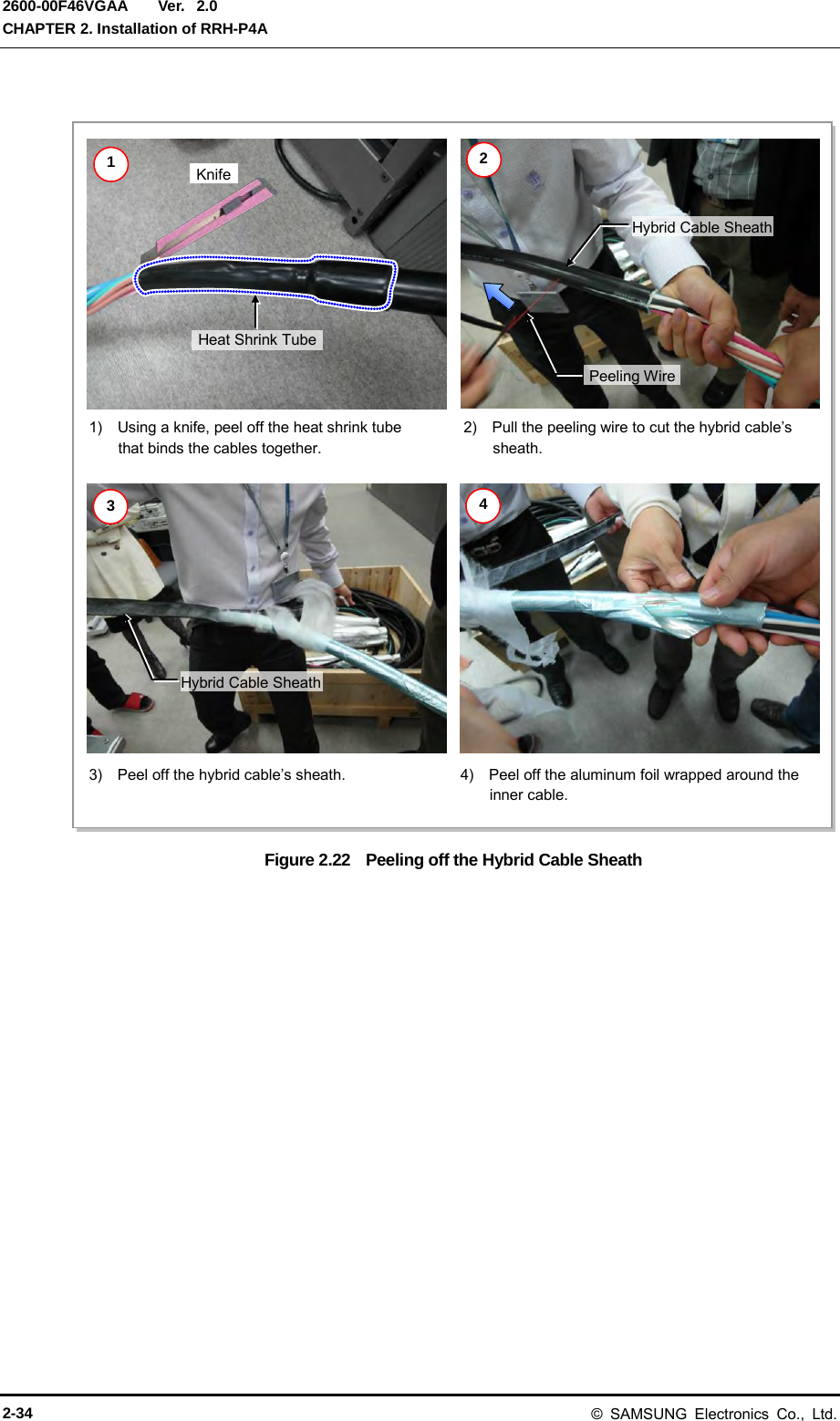
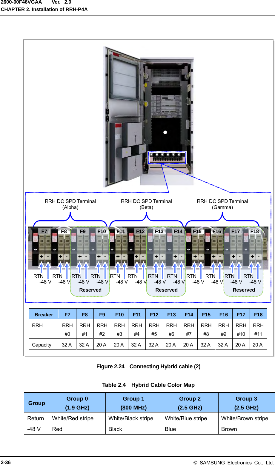
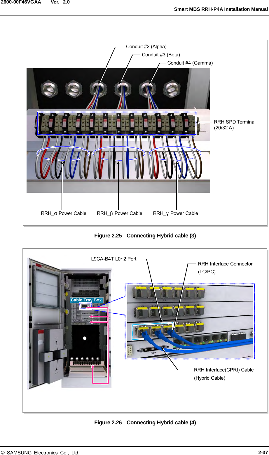
![Ver. Smart MBS RRH-P4A Installation Manual 2600-00F46VGAA 2.0 2.8.2 Connecting DU Cabinet side cable If the length of the hybrid cable is inadequate for the installation: 1) Measure the hybrid cable’s excess length. (With a white marker pen, mark the area of the cable where the double-layer sheath will be peeled when positioned in the conduit fitting.) 2) Using a knife, peel off the heat shrink tube that binds the cables together. 3) Pull the peeling wire in the inside of the hybrid cable’s double-layer sheath down to the previously marked area. 4) Peel off the hybrid cable’s sheath. 5) Peel off the aluminum foil wrapped around the inner cable. 6) For all power cables, leave 23.62 in. (600 mm) from where the double-layer sheath has been peeled off and cut the excess length off. 7) Unsheathe the end of the power cable wire at 0.59 in. (15 mm). 8) Using a conduit, insert the hybrid cable’s power cable and optic cable together into the cabinet. Be careful not to damage the optic cable’s connector. 9) From the inside of the cabinet, pull the optic cable to the right side of the system and attach temporarily with a cable tie. 10) Using a flat-head screwdriver (-, 1x100), turn the RRH power terminal’s screw counter-clockwise twice to 3 times. 11) Insert the power cable to the terminal according to its use and polarity, then fasten the screw with torque 1.3~1.59 lbf.ft (18~22 kgf.cm). 12) Bind two cables (-48 V, RTN) at 3.94 in. (100 mm) from the terminal using a cable tie. 13) Bury the optic cable following the system’s inner-right wall up to the UADU #0 side and bind using a cable tie. 14) Connect the connector of the optic cable to UADU’s designated port. (Loop the optic cable’s excess length respecting the bending radius [R=4.33 in. (110 mm)], and arrange it in the cable tray box. Be careful not to damage the optic cable during other works.) © SAMSUNG Electronics Co., Ltd. 2-33](https://usermanual.wiki/Samsung-Electronics-Co/SMM-BMR004.User-Manual/User-Guide-1983926-Page-63.png)
![Ver. Smart MBS RRH-P4A Installation Manual 2600-00F46VGAA 2.0 If the length of the hybrid cable is adequate for the installation: 1) For all power cables, leave 23.62 in. (600 mm) from where the double-layer sheath has been peeled off and cut the excess length off. 2) Unsheathe the end of the power cable wire at 0.59 in. (15 mm) length. 3) Using a conduit, insert the hybrid cable’s power cable and optic cable together into the cabinet. Be careful not to damage the optic cable’s connector. 4) From the inside of the cabinet, pull the optic cable to the right side of the system and attach temporarily with a cable tie. 5) Using a flat-head screwdriver (-, 1x100), turn the RRH power terminal’s screw counter-clockwise 2 to 3 times. 6) Insert the power cable to the terminal according to its usage and polarity, then fasten the screw with torque 1.3~1.59 lbf.ft (18~22 kgf.cm). 7) Bind two cables (-48 V, RTN) at 3.94 in. (100 mm) from the terminal using a cable tie. 8) Bury the optic cable following the system’s inner-right wall up to the UADU #0 side and bind using a cable tie. 9) Connect the connector of the optic cable to UADU’s designated port. (Loop the optic cable’s excess length respecting the bending radius [R=4.33 in. (110 mm)], and arrange it in the cable tray box. Be careful not to damage the optic cable during other works.) Figure 2.23 Connecting Hybrid cable (1) [Baseband Rack Right View] RRH Power Terminal Double-layer Sheath Peel-off Point 23.62 in. (600 mm) RRH CPRI Cable (Optic Cable) Flexible Pipe (2 in.) Max. 39.37 in. (1000 mm) Butyl Rubber Tape Hybrid Cable DC Power Cable © SAMSUNG Electronics Co., Ltd. 2-35](https://usermanual.wiki/Samsung-Electronics-Co/SMM-BMR004.User-Manual/User-Guide-1983926-Page-65.png)
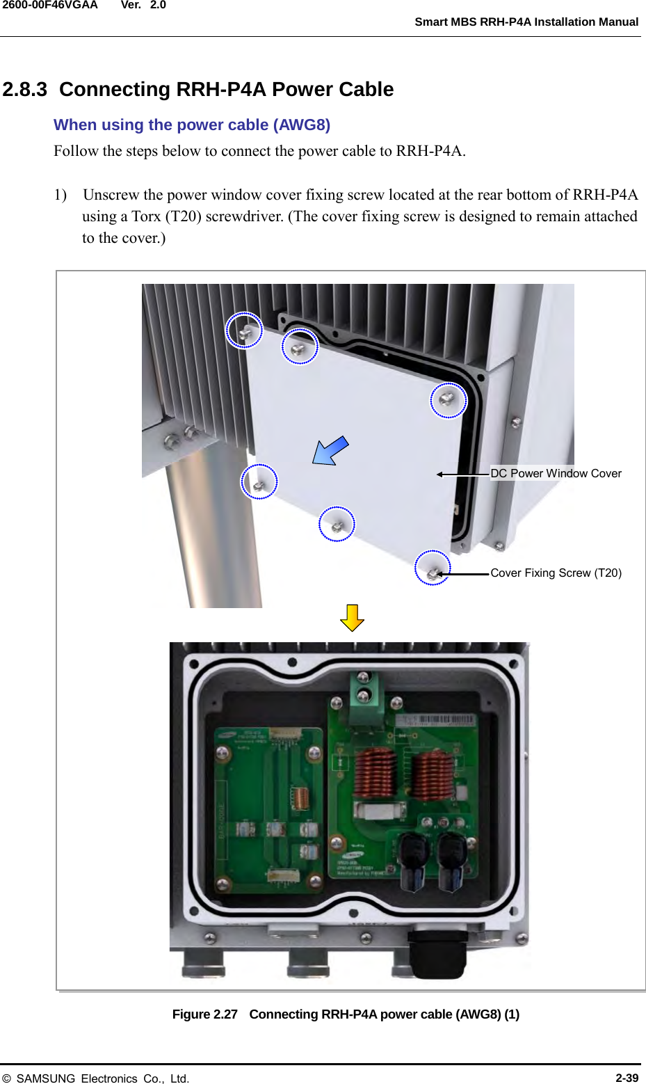
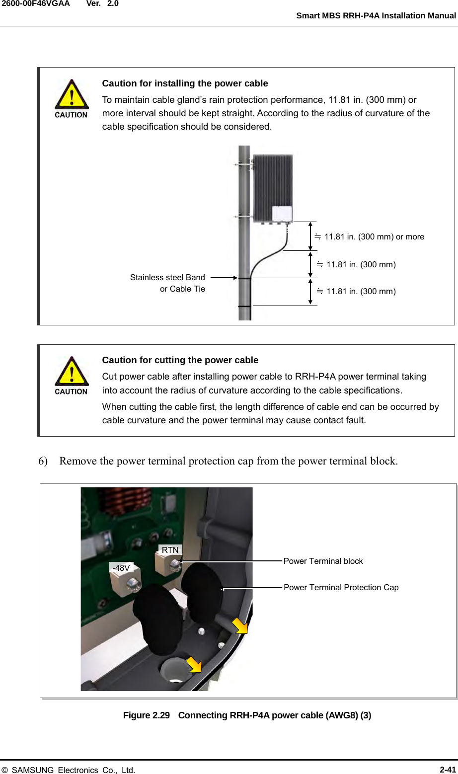
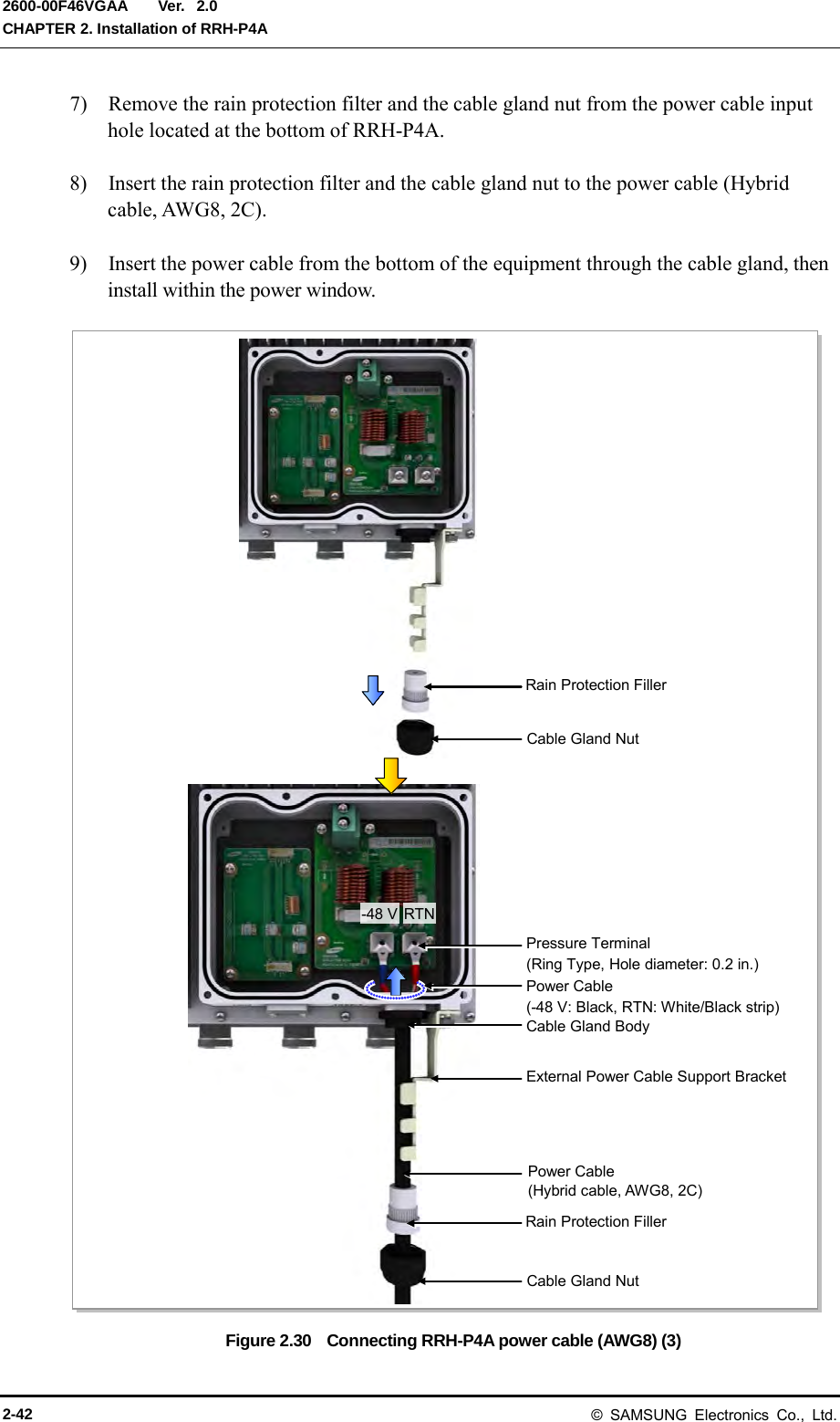
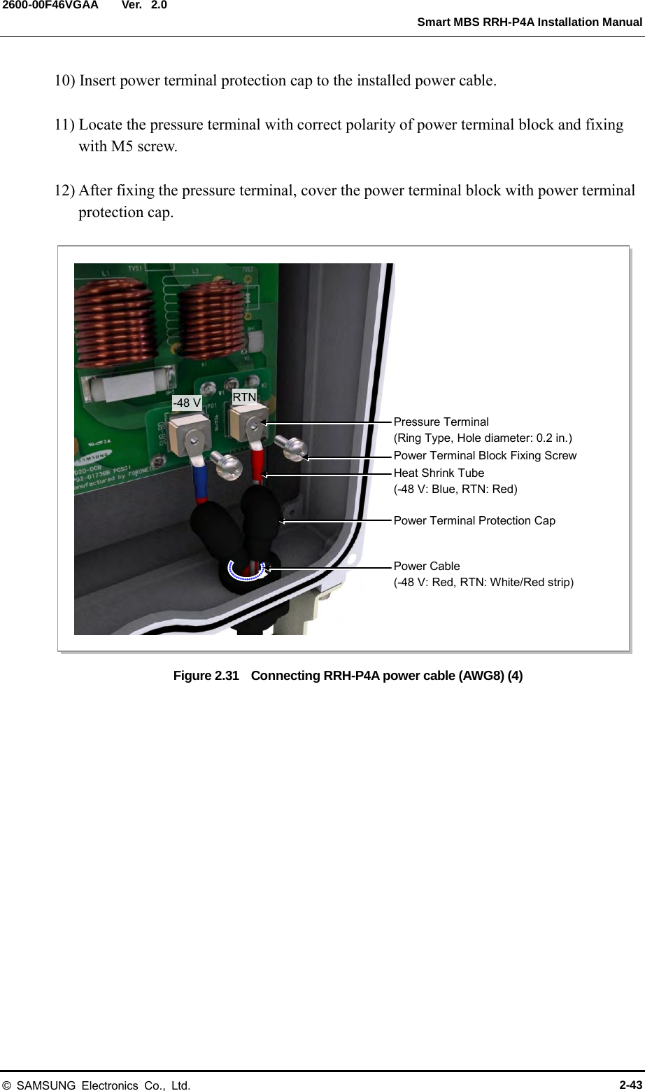
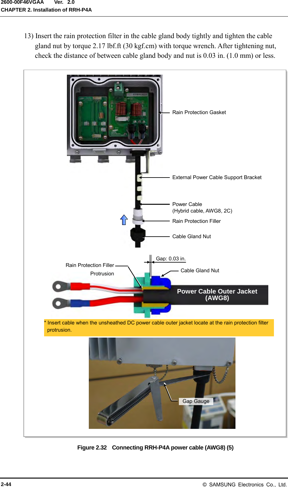
![Ver. CHAPTER 2. Installation of RRH-P4A 2600-00F46VGAA 2.0 2) Install one power cable (hybrid cable, AWG8, 2C) connected to the DU cabinet’s DC SPD terminal to the RRH-P4A power terminal. (Refer to the ‘Caution for installing the power cable’). 3) Cut cable installed to the power terminal. Unsheathe outer cable sheath at 1.77 in. (45 mm) length and peel off the inner wire at 0.39 in. (10 mm) length. 4) Insert heat shrink tube [0.59 in. (15mm)] at the inner wire and shrink the pressure terminal (AWG8). pressure terminal: AWG8, ring type, hole diameter: 0.2 in. (5.3 mm) 5) Locate heat shrink tube (-48 V: blue, RTN: red) at pressure terminal and shrink the heat shrink tube using a heat gun. Figure 2.28 Connecting RRH-P4A power cable (AWG8) (2) DC Power Cable (AWG8) 0.58~0.6 in. (14.7~15.4 mm) 1.77 in. (45 mm) 0.39 in. (10 mm) 0.59 in. (15 mm) RTN -48 V DC Power Cable (AWG8) DC Power Cable (AWG8) 1.38 in. (35 mm) 2-40 © SAMSUNG Electronics Co., Ltd.](https://usermanual.wiki/Samsung-Electronics-Co/SMM-BMR004.User-Manual/User-Guide-1983926-Page-70.png)
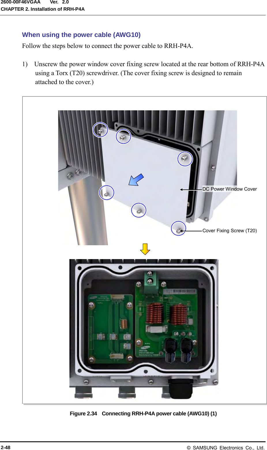
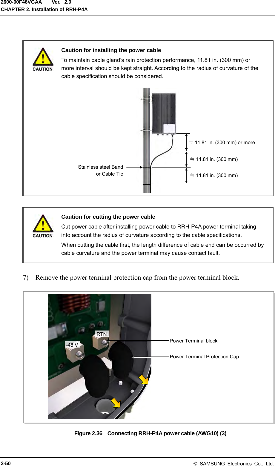
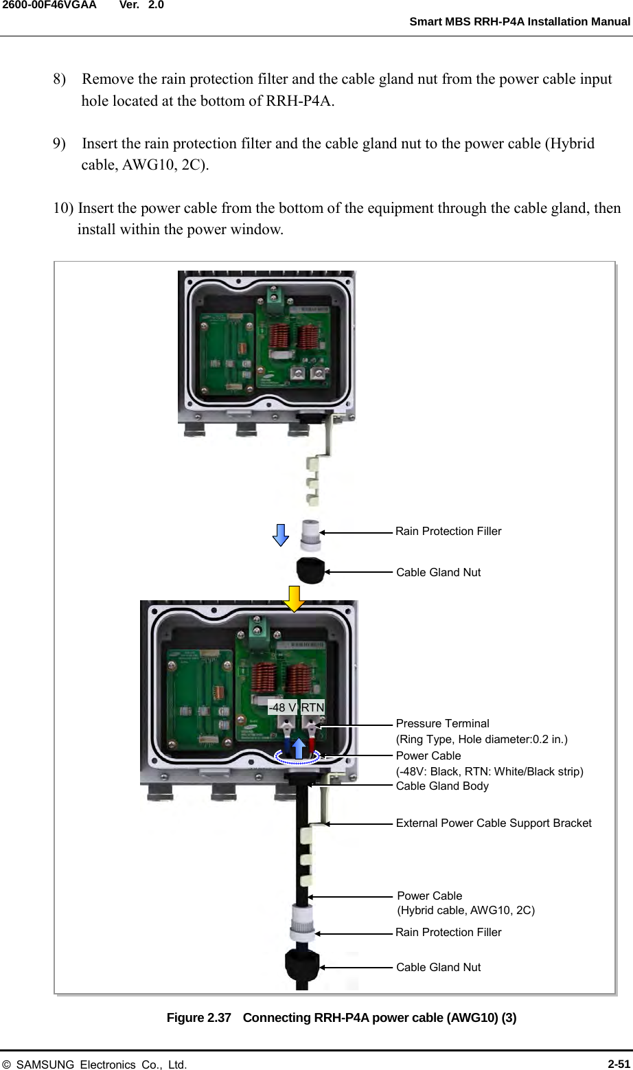
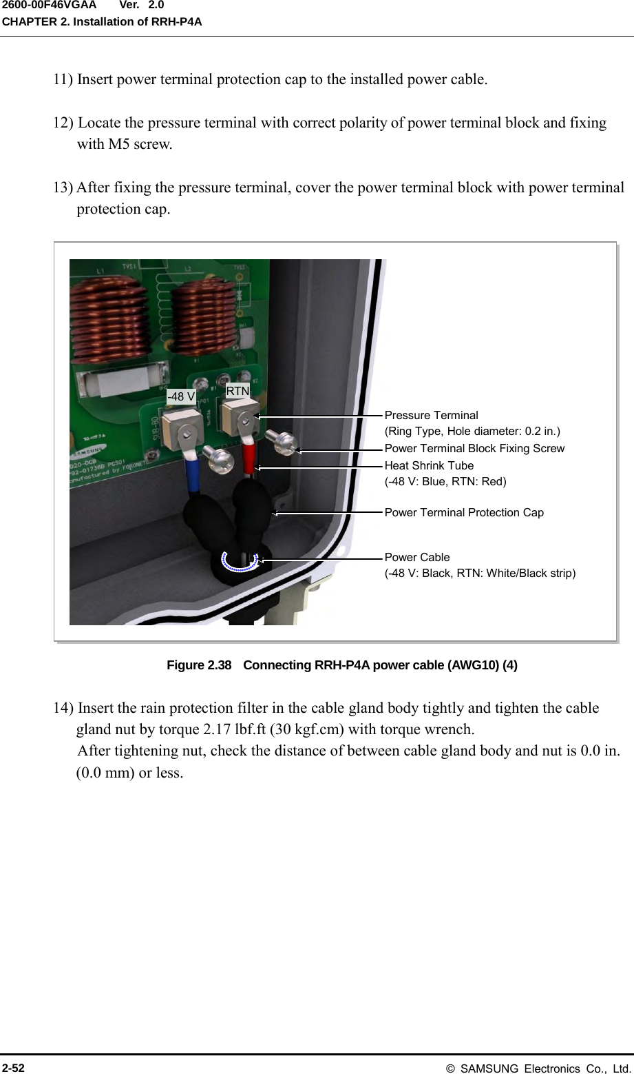
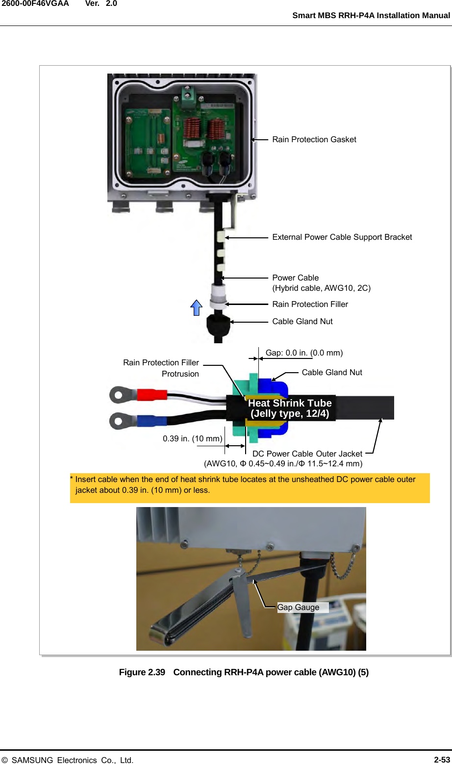
![Ver. Smart MBS RRH-P4A Installation Manual 2600-00F46VGAA 2.0 2) Install one power cable (hybrid cable, AWG10, 2C) connected to the DU cabinet’s DC SPD terminal to the RRH-P4A power terminal. (Refer to the ‘Caution for installing the power cable’). 3) Cut cable installed to the power terminal. Unsheathe outer cable sheath at 1.38 in. (35 mm) length and peel off the inner wire at 0.39 in. (10 mm) length. 4) Insert heat shrink tube [0.59 in. (15 mm)] at the inner wire and shrink the pressure terminal (AWG10) pressure terminal: AWG10, ring type, hole diameter: 0.2 in. (5.3 mm) 5) Locate heat shrink tube (-48 V: blue, RTN: red) at pressure terminal and shrink the heat shrink tube using a heat gun. 6) Insert heat shrink tube [jelly type, 12/4, 1.97 in. (50 mm)] at the position of peeled external cover and shrink the heat shrink tube using a heat gun. At this time, match the end of unsheathed external cable and the end of heat shrink tube. Figure 2.35 Connecting RRH-P4A power cable (AWG10) (2) DC Power Cable (AWG10) 0.45~0.49 in. (11.5~12.4 mm) 1.38 in. (35 mm) 0.59 in. (15 mm) RTN -48 V 0.98 in. (25 mm) 0.39 in. (10 mm) Heat Shrink Tube (Jelly Type, 12/4, Black) 0.98 in. (25 mm) DC Power Cable (AWG10) DC Power Cable (AWG10) © SAMSUNG Electronics Co., Ltd. 2-49](https://usermanual.wiki/Samsung-Electronics-Co/SMM-BMR004.User-Manual/User-Guide-1983926-Page-79.png)
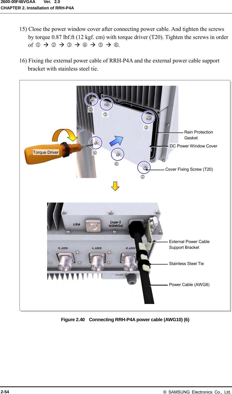
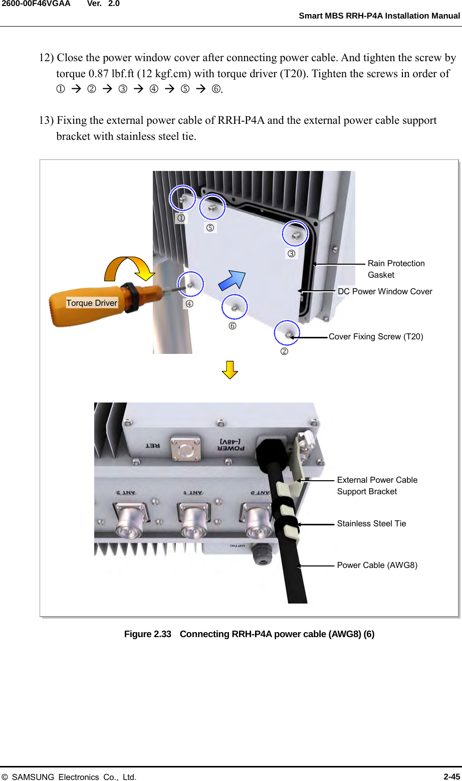
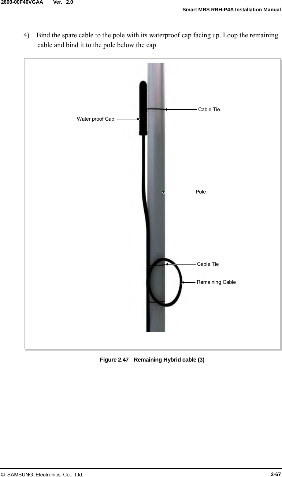
![Ver. Smart MBS RRH-P4A Installation Manual 2600-00F46VGAA 2.0 2.8.6 Remaining Hybrid cable Follow the steps below to organize the remaining cable after connecting the hybrid cable (power cable, CPRI cable) to RRH-P4A. 1) Loop the excess length of the power cable and CPRI cable, and attach to the RRH-P4A fixing pole using a cable tie. Ensure to respect the optic cable’s bending radius of [R=4.33 in. (110 mm)]. 2) Bind the power cable and CPRI cable together with the feeder line using a cable tie. Figure 2.45 Remaining Hybrid cable (1) Feeder Line RRH-P4A RRH-P4A Fixing Pole Remaining cable Cable Tie Cable Tie © SAMSUNG Electronics Co., Ltd. 2-65](https://usermanual.wiki/Samsung-Electronics-Co/SMM-BMR004.User-Manual/User-Guide-1983926-Page-95.png)
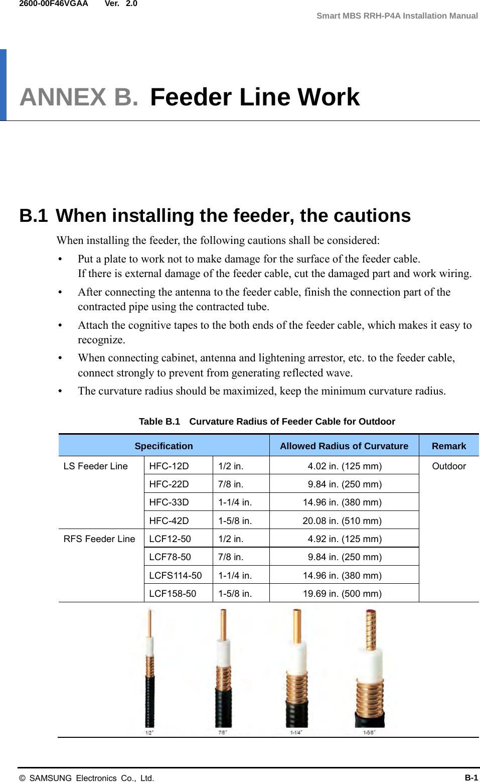
![Ver. ANNEX B. Feeder Line Work 2600-00F46VGAA 2.0 Figure B.3 Feeder Cable Grounding (3) 7.87 in. (200 mm) Heating Gun Heat Shrink Tube Heat Shrink Tube 7) Align the heat shrink tube inserted when installing the feeder line into the fixing part of the ground kit. - Heat shrink tube: Φ 1.65 in., 7.87 in (Φ 42 mm, 200 mm) 8) Shrink the heat shrink tube [jelly type, 7.87 in. (200 mm)] by heating gun. 7 8 B-6 © SAMSUNG Electronics Co., Ltd.](https://usermanual.wiki/Samsung-Electronics-Co/SMM-BMR004.User-Manual/User-Guide-1983926-Page-112.png)
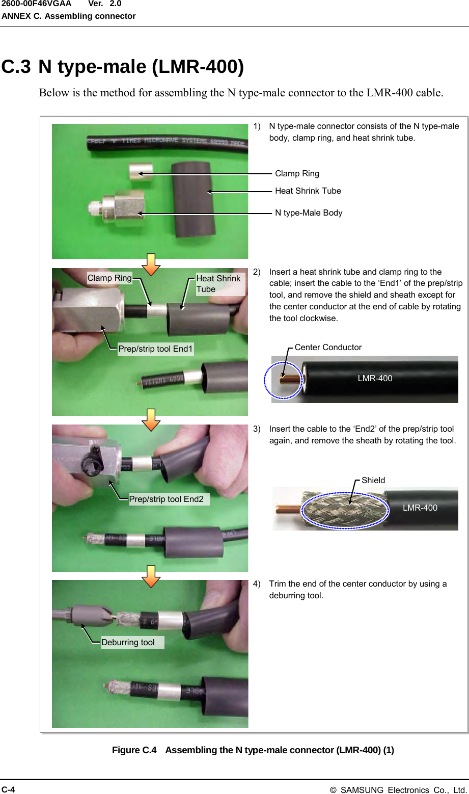
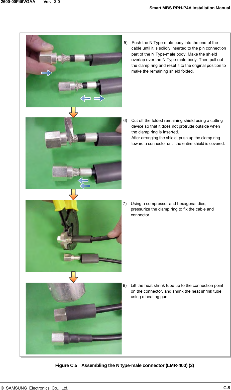
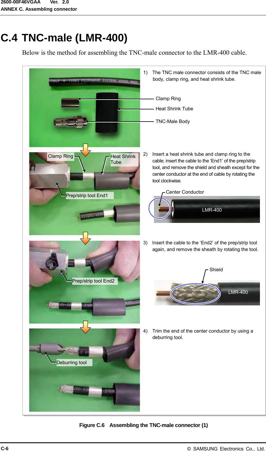
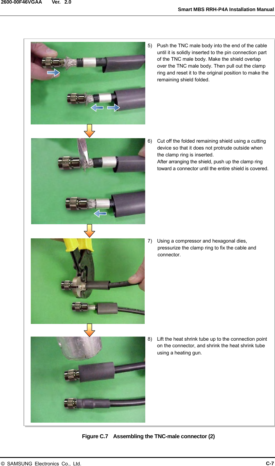
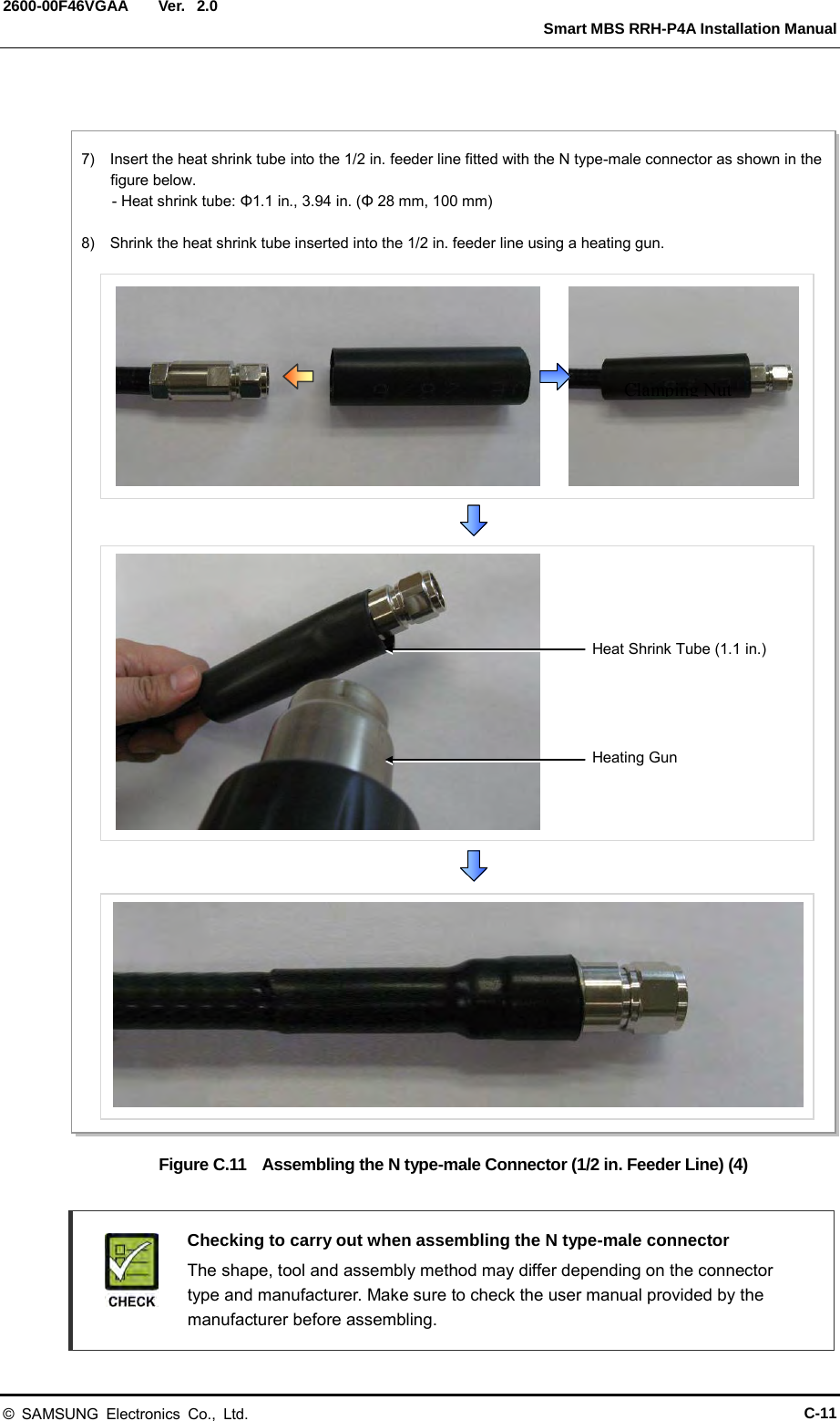
![Ver. ANNEX C. Assembling connector 2600-00F46VGAA 2.0 C.5 N type-male (1/2 in. feeder line) Below is the method for assembling the N-type-male connector to the 1/2 in. feeder line. Figure C.8 Assembling the N type-male Connector (1/2 in. Feeder Line) (1) 1) The components of the N type-male are an N type-male body, an insert ring, a clamp nut, O-ring, and a heat shrink tube, and it is assembled using the wire stripper, trimming tool, spanner, etc. 2) Using a stripping tool or a knife, strip the 1/2 in. feeder line by 1 in. (25 mm) from the end, as shown in the figure below. 1 in. (25 mm) 1/2 in. Feeder Line Conductor 1/2 in. Feeder Line Jacket Trimming Tool Heat Shrink Tube [1.1 in. (28 mm)] Insert Ring N type-Male Body Clamping Nut 1/2 in. Feeder Line O-Ring C-8 © SAMSUNG Electronics Co., Ltd.](https://usermanual.wiki/Samsung-Electronics-Co/SMM-BMR004.User-Manual/User-Guide-1983926-Page-122.png)
![Ver. Smart MBS RRH-P4A Installation Manual 2600-00F46VGAA 2.0 Figure C.9 Assembling the N type-male Connector (1/2 in. Feeder Line) (2) Trimming Tool 3) Remove the end [0.43 in. (11 mm)] and the coat [0.39 in. (10 mm)] of the external conductor using a trimming tool. Collet 4) Insert the internal conductor into the deburring hole at the bottom of the trimming tool to trim it. 0.94 in. (24 mm) 0.43 in. (11 mm) © SAMSUNG Electronics Co., Ltd. C-9](https://usermanual.wiki/Samsung-Electronics-Co/SMM-BMR004.User-Manual/User-Guide-1983926-Page-123.png)

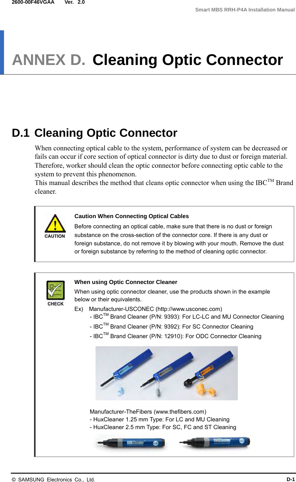
![Ver. ANNEX D. Cleaning Optic Connector 2600-00F46VGAA 2.0 D.2 IBCTM Brand Cleaner Method that uses IBCTM Brand Cleaner is as follows: D.2.1 IBCTM brand type cleaner (P/N 9393) Method that uses IBCTM Brand Cleaner (P/N 9393) for LC-LC and MU connector is as follows: Figure D.1 Optic Connector Cleaner (IBCTM Brand Type Cleaner: P/N 9393) Outer Shell [Optic Connector Cleaner Configuration] Nozzle Guide Cap Lock Button (for Extend Nozzle) [Nozzle Extension] [In Case of LC type Connector (Plug)] Guide Cap Guide Cap Cover [In Case of LC type Connector (Jack)] Guide Cap Lock Button (for Extend Nozzle) D-2 © SAMSUNG Electronics Co., Ltd.](https://usermanual.wiki/Samsung-Electronics-Co/SMM-BMR004.User-Manual/User-Guide-1983926-Page-136.png)
![Ver. Smart MBS RRH-P4A Installation Manual 2600-00F46VGAA 2.0 Optic Module Cleaning (LC type Jack) Figure D.2 Optic Module Cleaning (LC type Jack) Guide Cap 1) To clean the optic module, remove the guide cap from the cleaner (P/N: 9393). 2) Insert a cleaner guide cap to every core of the optic module. Clean it by pushing the outer shell toward the nozzle until you hear the sound of the detergent being sprayed. (Repeat once or twice.) Outer Shell Nozzle Nozzle Outer Shell Optic Module [IBC Brand Cleaner: P/N 9393] © SAMSUNG Electronics Co., Ltd. D-3](https://usermanual.wiki/Samsung-Electronics-Co/SMM-BMR004.User-Manual/User-Guide-1983926-Page-137.png)
![Ver. ANNEX D. Cleaning Optic Connector 2600-00F46VGAA 2.0 Optic Cable Connector Cleaning (LC type plug) Figure D.3 Optic Cable Connector Cleaning (LC type plug) Guide Cap Guide Cap Cover 1) To clean the optic cable connector, open the guide cap cover from the cleaner (P/N: 9393). 2) Insert a cleaner guide cap to every core of the optic cable connector. Clean it by pushing the outer shell toward the nozzle until you hear the sound of the detergent being sprayed. (Repeat once or twice.) Outer Shell Nozzle Guide Cap Nozzle Outer Shell LC Type Connector [IBC Brand Cleaner: P/N 9393] D-4 © SAMSUNG Electronics Co., Ltd.](https://usermanual.wiki/Samsung-Electronics-Co/SMM-BMR004.User-Manual/User-Guide-1983926-Page-138.png)
![Ver. Smart MBS RRH-P4A Installation Manual 2600-00F46VGAA 2.0 Measuring the Optical Output and Connecting the Optic Connector Figure D.4 Measuring the Optical Output and Connecting the Optic Connector [Optic Powermeter] [LC/PC Plug] 1) Check the optical output again using an optic power meter. 2) If the optical output measurement result meets the reference value, clean the connector again and connect it. If the measurement result does not meet the reference value, discard the cable, replace it with a new cable, and then clean the new one and connect it to the system. © SAMSUNG Electronics Co., Ltd. D-5](https://usermanual.wiki/Samsung-Electronics-Co/SMM-BMR004.User-Manual/User-Guide-1983926-Page-139.png)

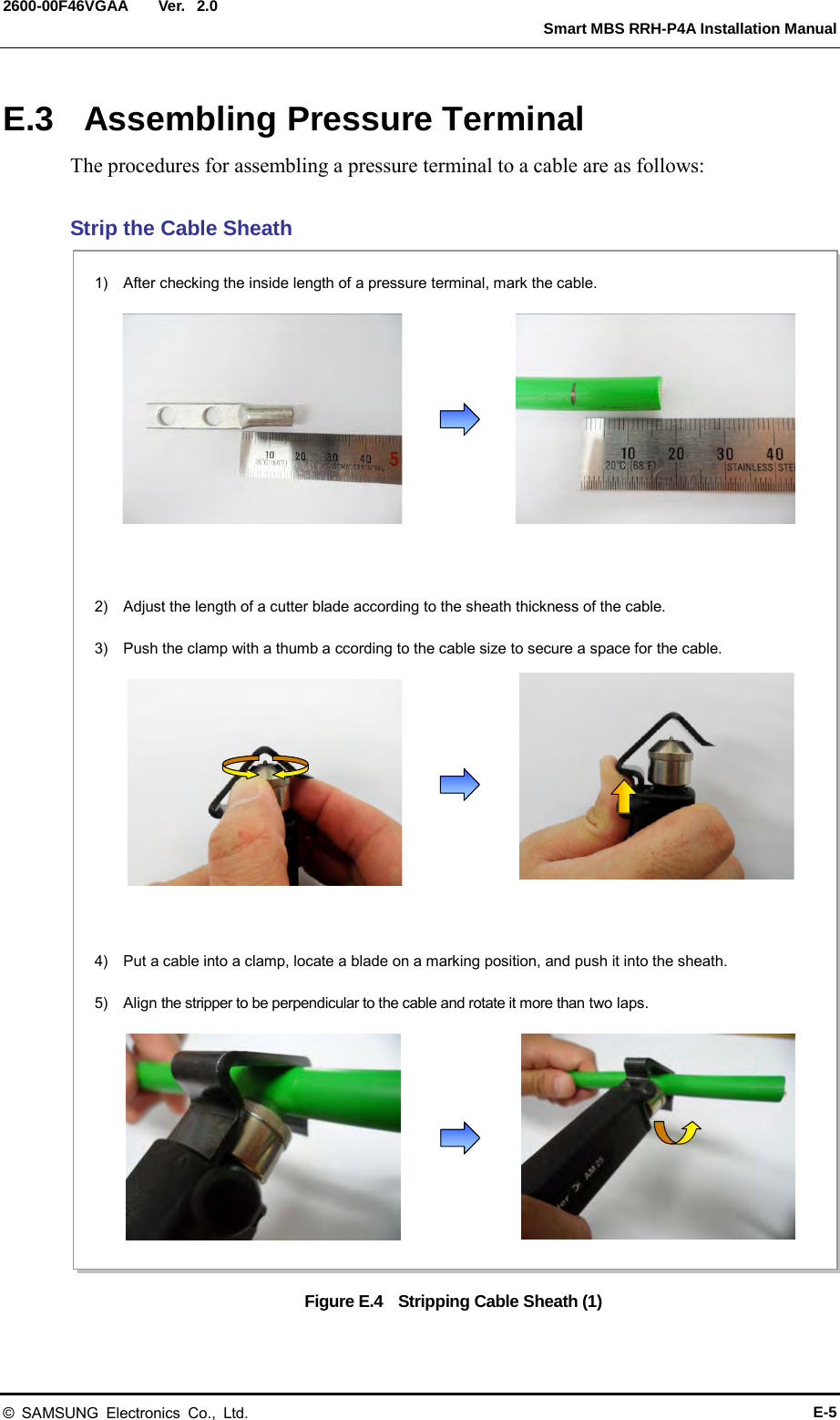
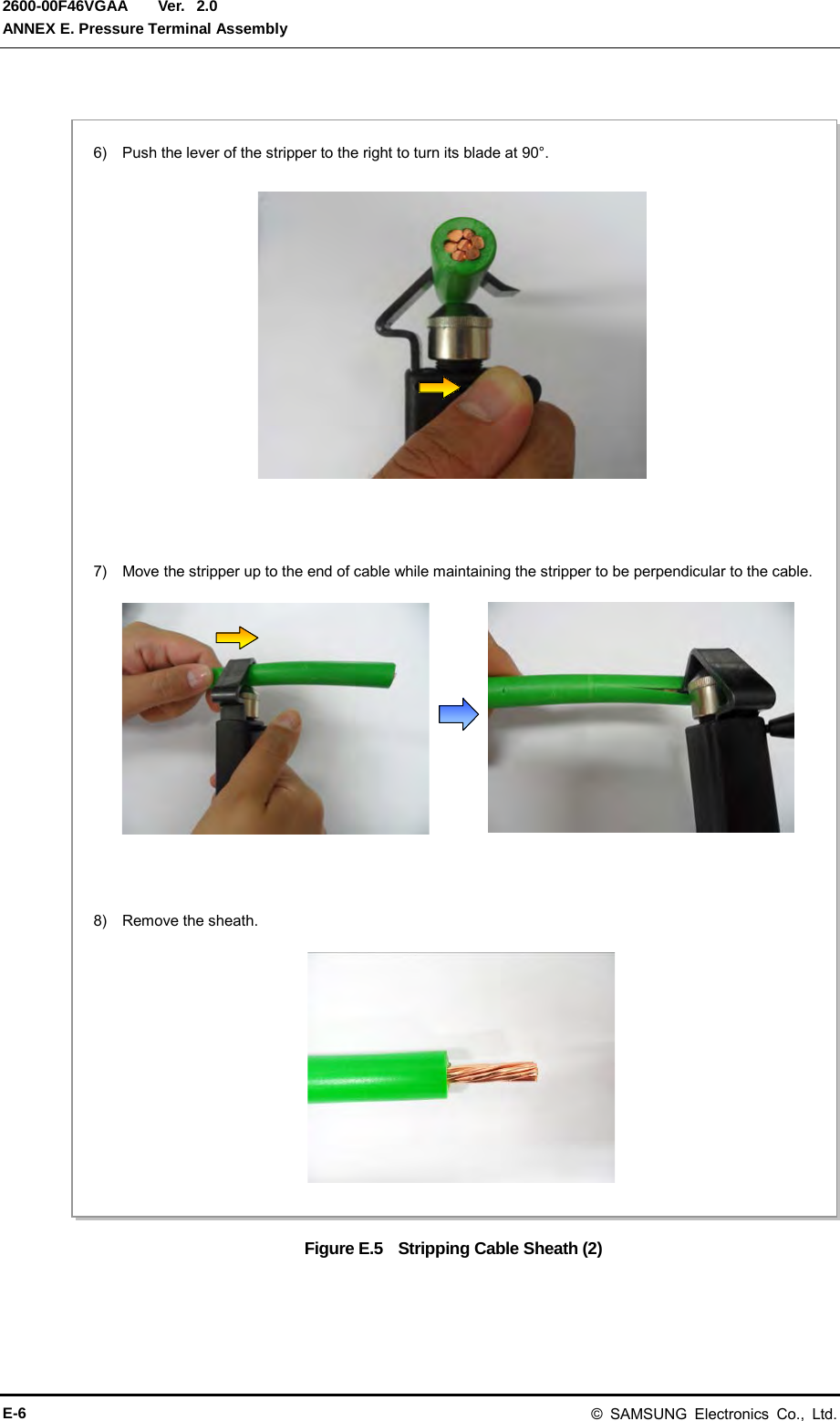
![Ver. Smart MBS RRH-P4A Installation Manual 2600-00F46VGAA 2.0 ANNEX E. Pressure Terminal Assembly E.1 Preparations The followings must be prepared to connect a pressure terminal to a cable. Figure E.1 Preparations [Cable Cutter] [Wire Stripper] [Handheld Compressor] [Hydraulic Press] [Heating Gun] [Marking Pen] [Cutter Blade] [Steel Ruler] [Scissors] [Cable] [Pressure Terminal] [Heat Shrink Tube] © SAMSUNG Electronics Co., Ltd. E-1](https://usermanual.wiki/Samsung-Electronics-Co/SMM-BMR004.User-Manual/User-Guide-1983926-Page-141.png)
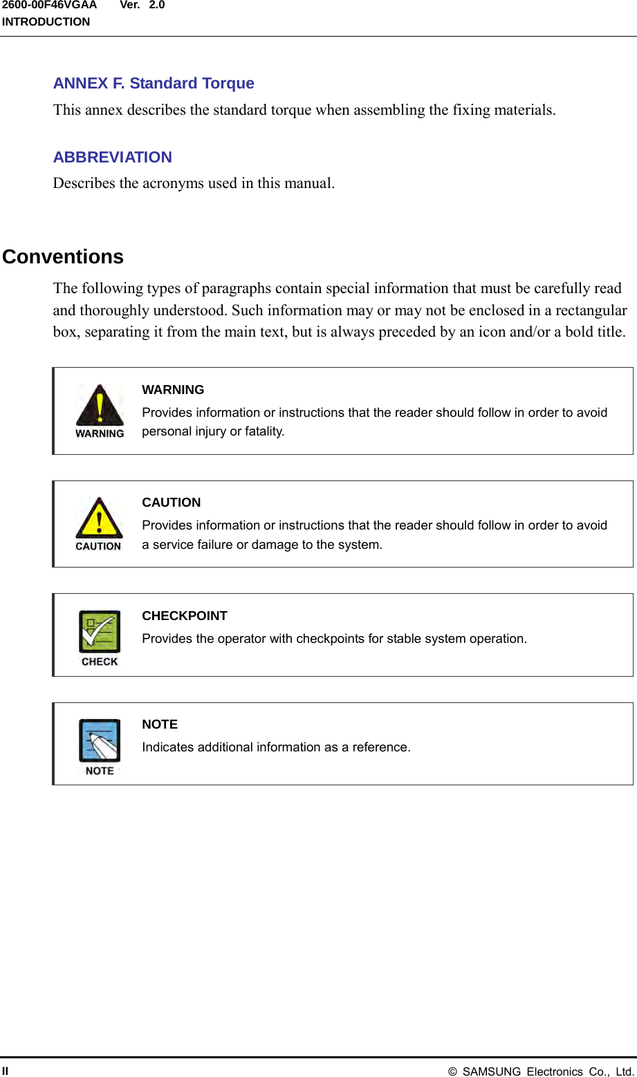
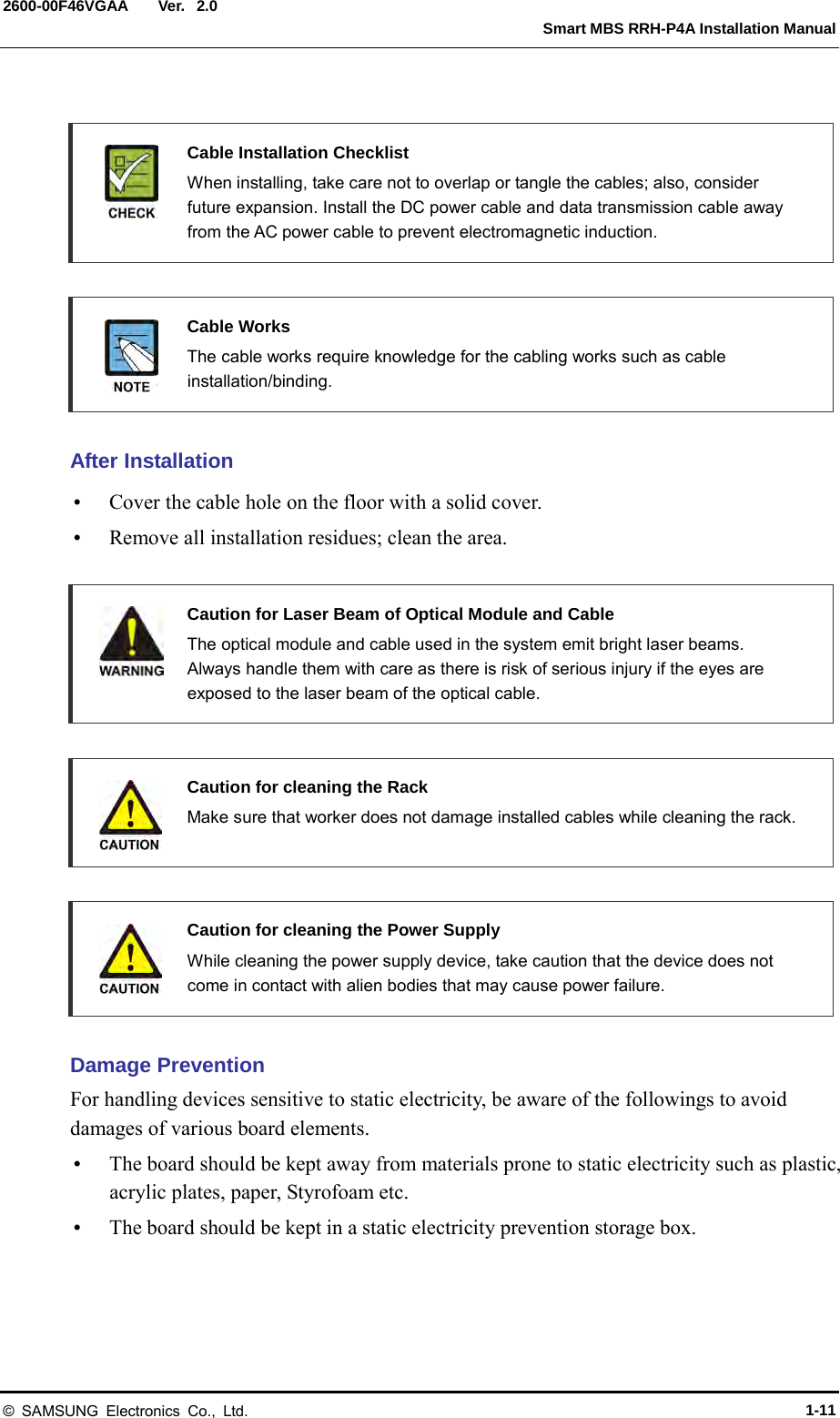
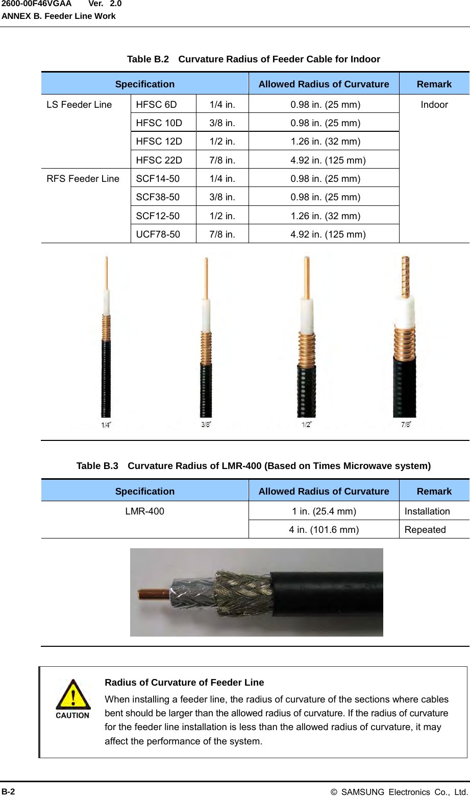
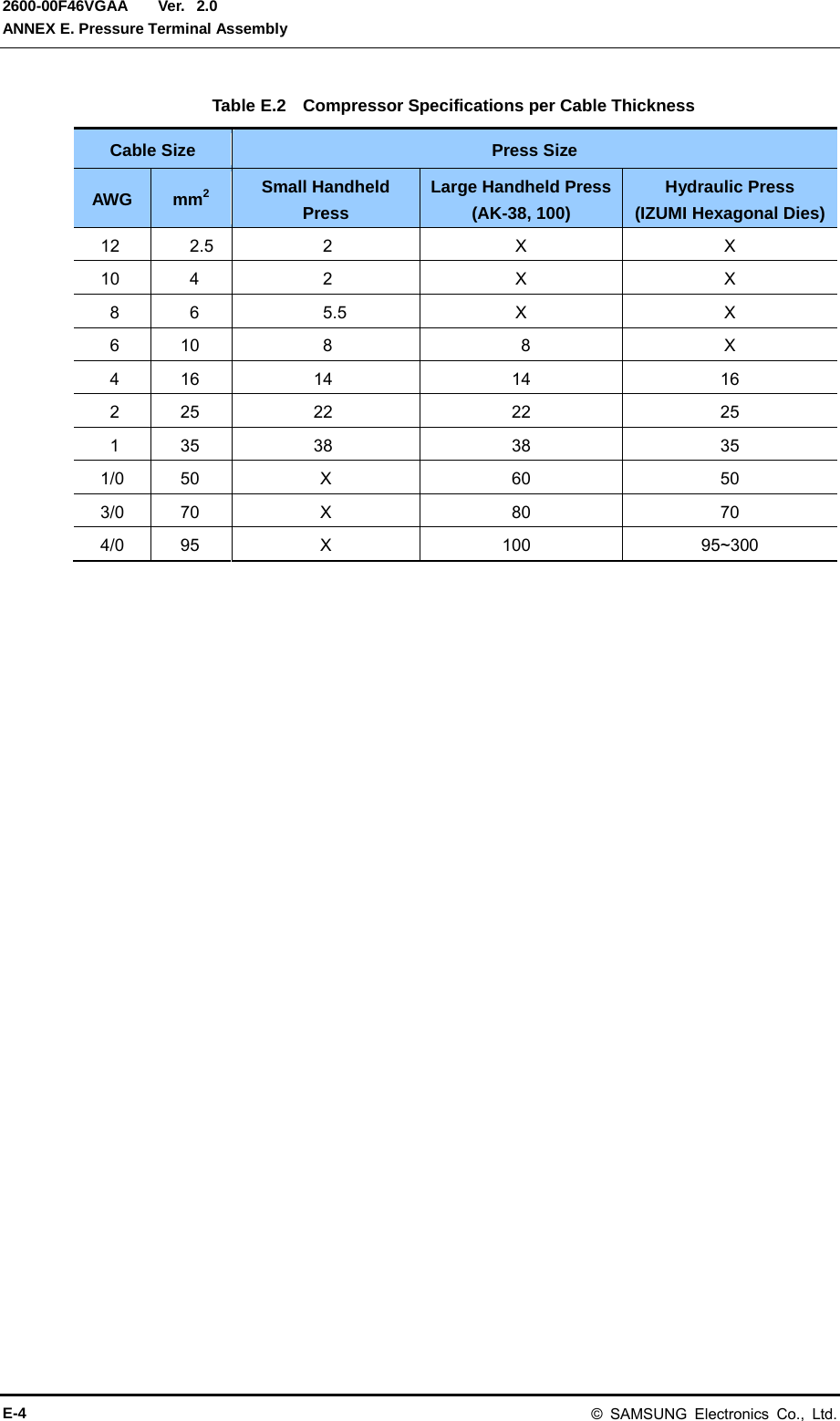
![Ver. ANNEX E. Pressure Terminal Assembly 2600-00F46VGAA 2.0 E.2 Pressure Reference Table The pressure reference table used to assemble a pressure terminal to a cable is shown below. Table E.1 Pressure Reference Table for Pressure Terminal Category Copper tube length of a pressure terminal Number of pressure points In. mm Hand 0.43 in. or less 11 mm or less 1 Hand 0.47~0.59 in. 12~15 mm 2 Hand 0.63~0.91 in. 16~23 mm 3 Hand 0.94~1.26 in. 24~32 mm 4 Hand 1.3 in. or more 33 mm or more 5 Hydraulic 1.18 in. or less 30 mm or less 2 Hydraulic 1.22~1.85 in. 31~47 mm 3 Hydraulic 1.89~2.48 in. 48~63 mm 4 Hydraulic 2.52 in. or more 64 mm or more 5 Figure E.2 Pressure Reference Drawing (Handheld Compressor) [1-spot] [2-spot] [3-spot] [4-spot] Unit: in. (mm) 0.43 (11) 0.18 (4.5) 0.47 (12) 0.59 (15) 0.63 (16) 0.91 (23) 0.94 in. (24) 1.26 (32) 0.63 (16) 0.18 (4.5) Copper Tube Starting Middle of Copper Tube Arbitrary Fixing Reference Points E-2 © SAMSUNG Electronics Co., Ltd.](https://usermanual.wiki/Samsung-Electronics-Co/SMM-BMR004.User-Manual/User-Guide-1983926-Page-142.png)
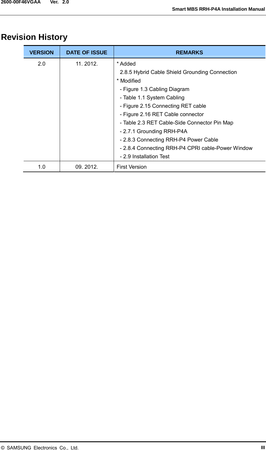
![Ver. Smart MBS RRH-P4A Installation Manual 2600-00F46VGAA 2.0 Figure E.3 Pressure Reference Drawing (Hydraulic Press) Unit: in. (mm) [2-spot] [3-spot] [4-spot] 1.18 (30) [4-spot] Copper Tube Starting Duplicate Pressure Arbitrary Fixing Reference Points 0.53 (13.5) 1.22 (31) 0.53 (13.5) 1.22 (31) 1.85 (47) 1.89 (48) 2.48 (63) 2.52 (64) © SAMSUNG Electronics Co., Ltd. E-3](https://usermanual.wiki/Samsung-Electronics-Co/SMM-BMR004.User-Manual/User-Guide-1983926-Page-143.png)
![Ver. Smart MBS RRH-P4A Installation Manual 2600-00F46VGAA 2.0 Checking When Using A Wire Stripper A wire stripper is used differently depending on its manufacturer or type. Therefore, refer to the user manual enclosed with the product. The specifications and cautions of a wire stripper described in this manual are as follows: Vender: Weidmuller Model: Weidmuller-AM25 (Order No- 9001080000) Specifications: For outer diameter 0.24- 0.94 in. (6-24 mm) PVC clothing Up to 0.18 in. (4.5 mm) clothing cutting depth - To prevent the cutter blade of a wire stripper from touching the cable conductor, adjust the length of cutter blade by checking the cable sheath thickness. - Make sure that the cutter blade goes into the cable sheath completely. - Rotate the wire stripper perpendicularly to the cable. [X] [O] © SAMSUNG Electronics Co., Ltd. E-7](https://usermanual.wiki/Samsung-Electronics-Co/SMM-BMR004.User-Manual/User-Guide-1983926-Page-147.png)