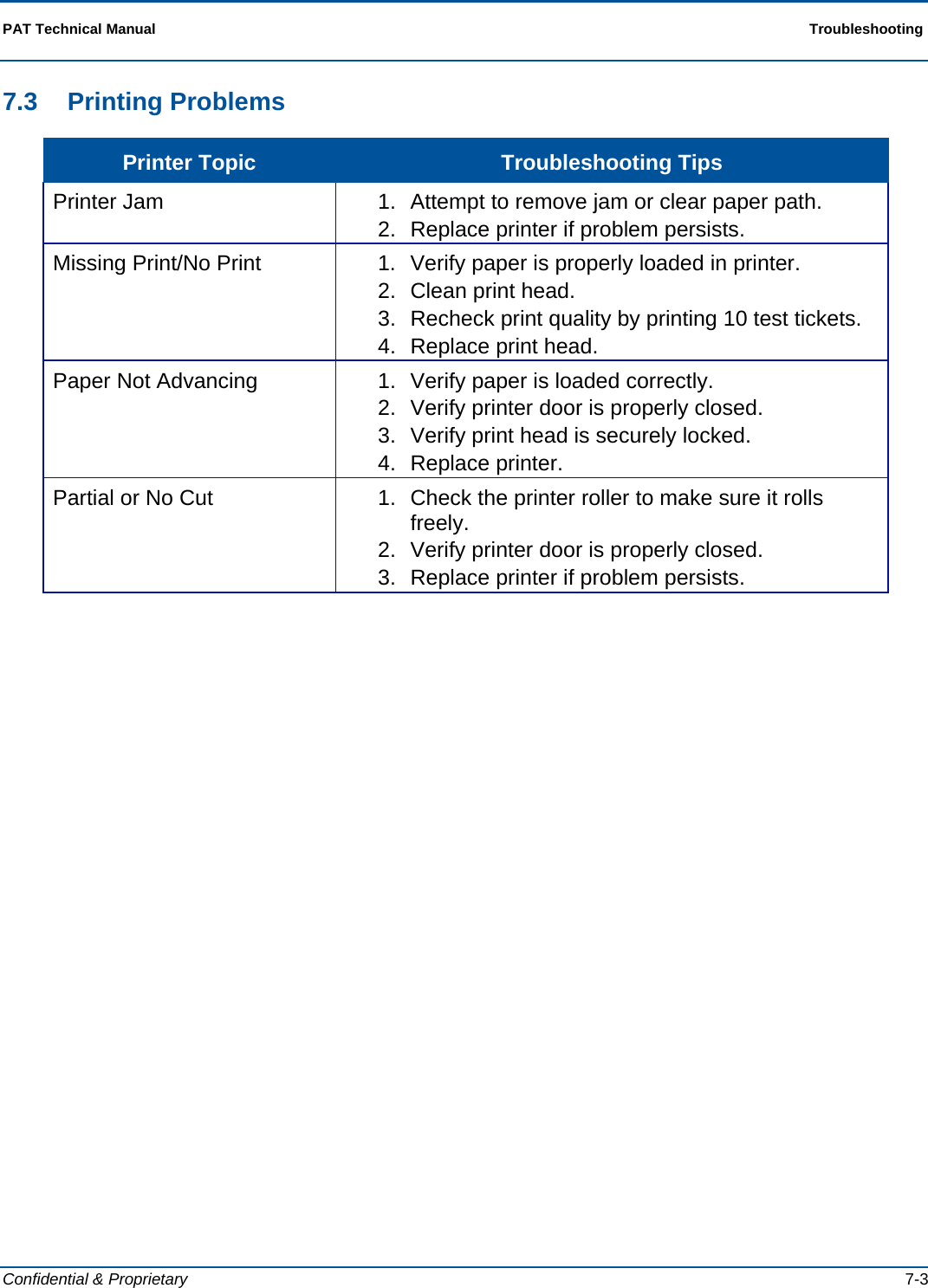
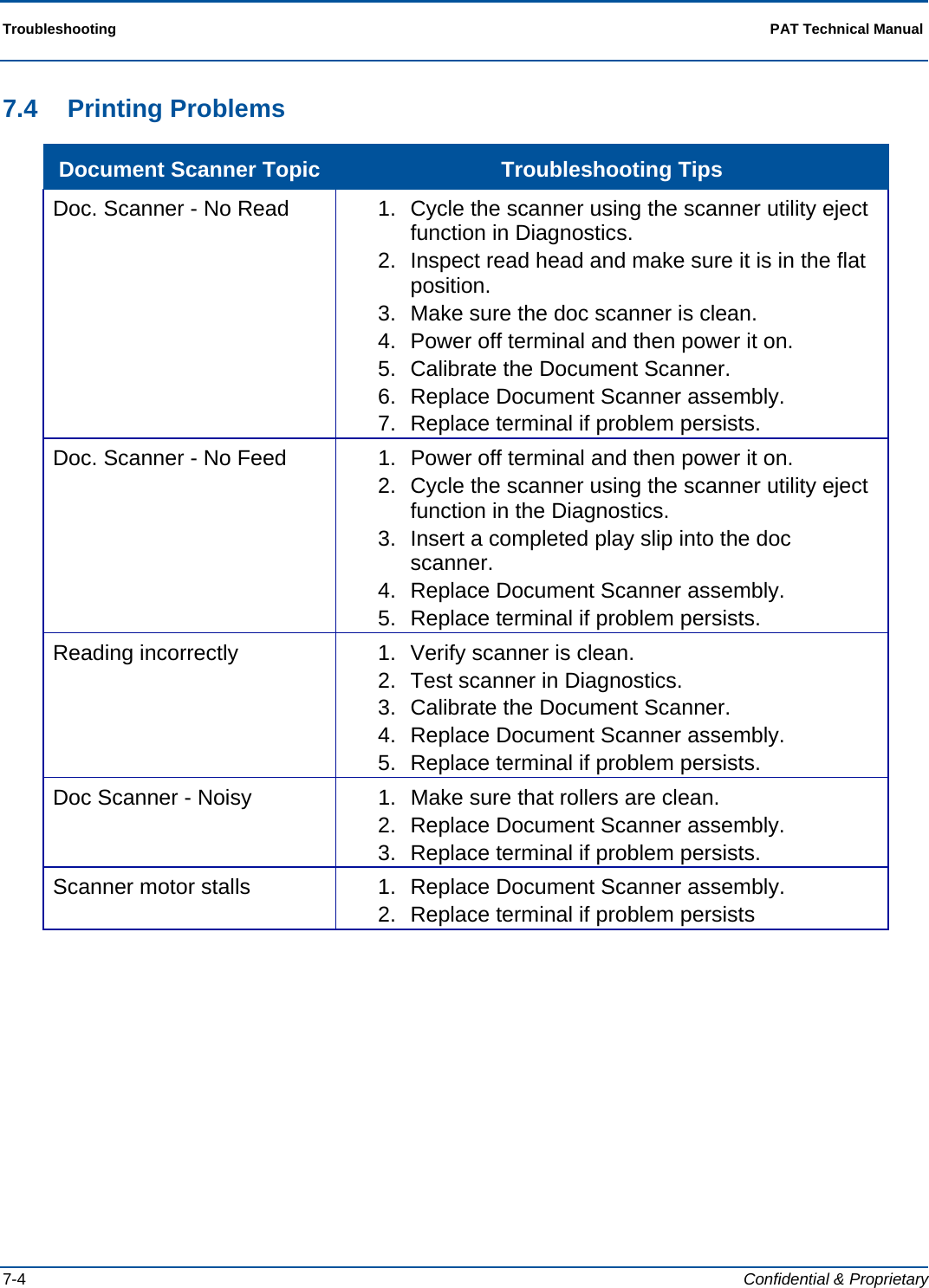
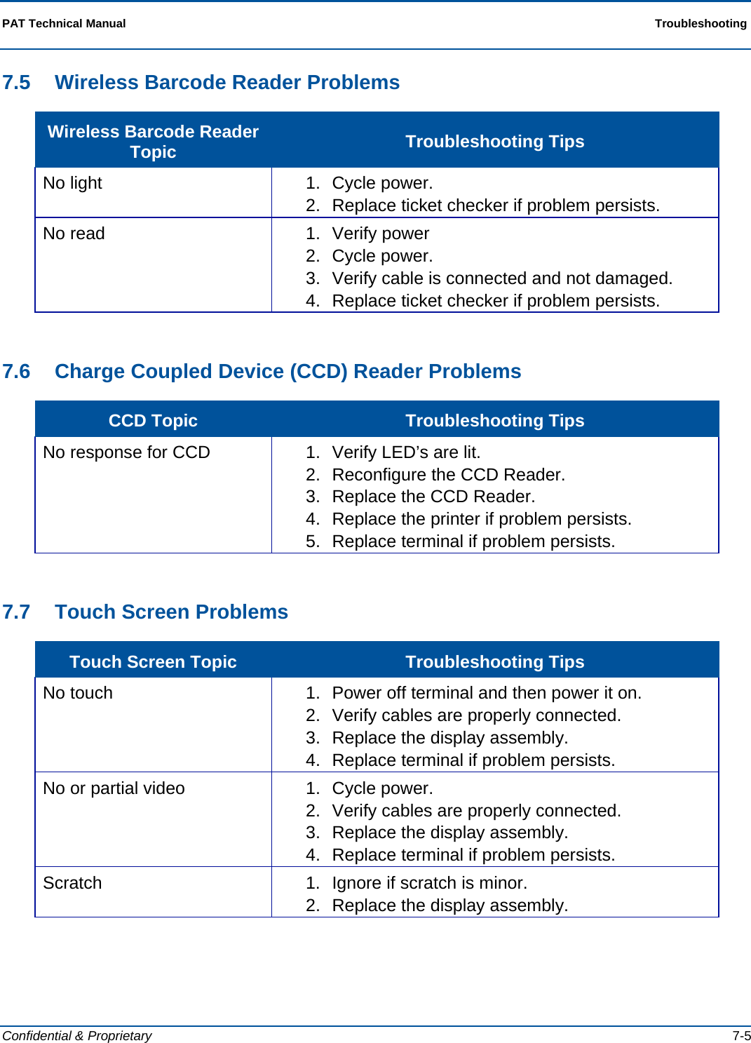
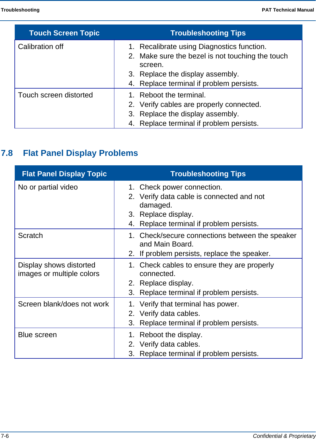
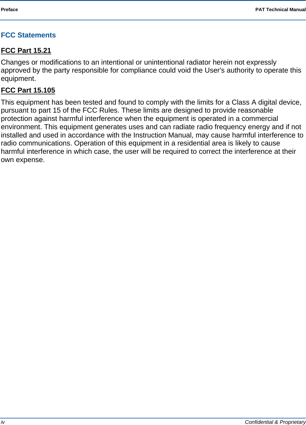
Scientific Games ITVM01 LOTTERY TICKET TERMINAL User Manual
Scientific Games International LOTTERY TICKET TERMINAL Users Manual
UserManual.wiki
>
Scientific Games
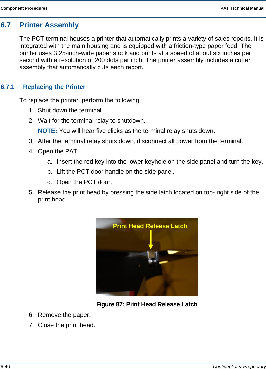
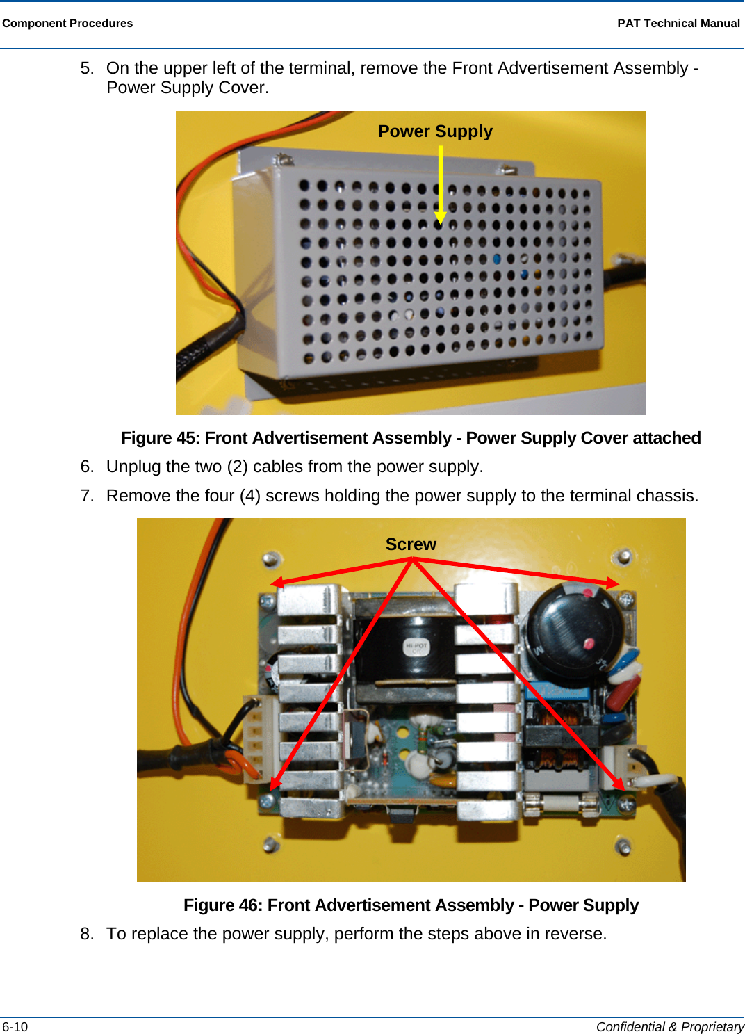
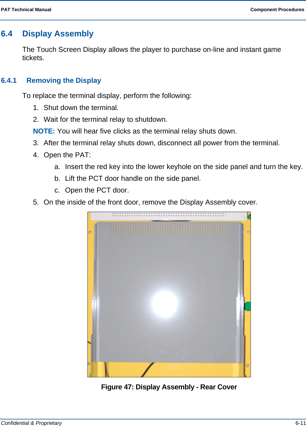
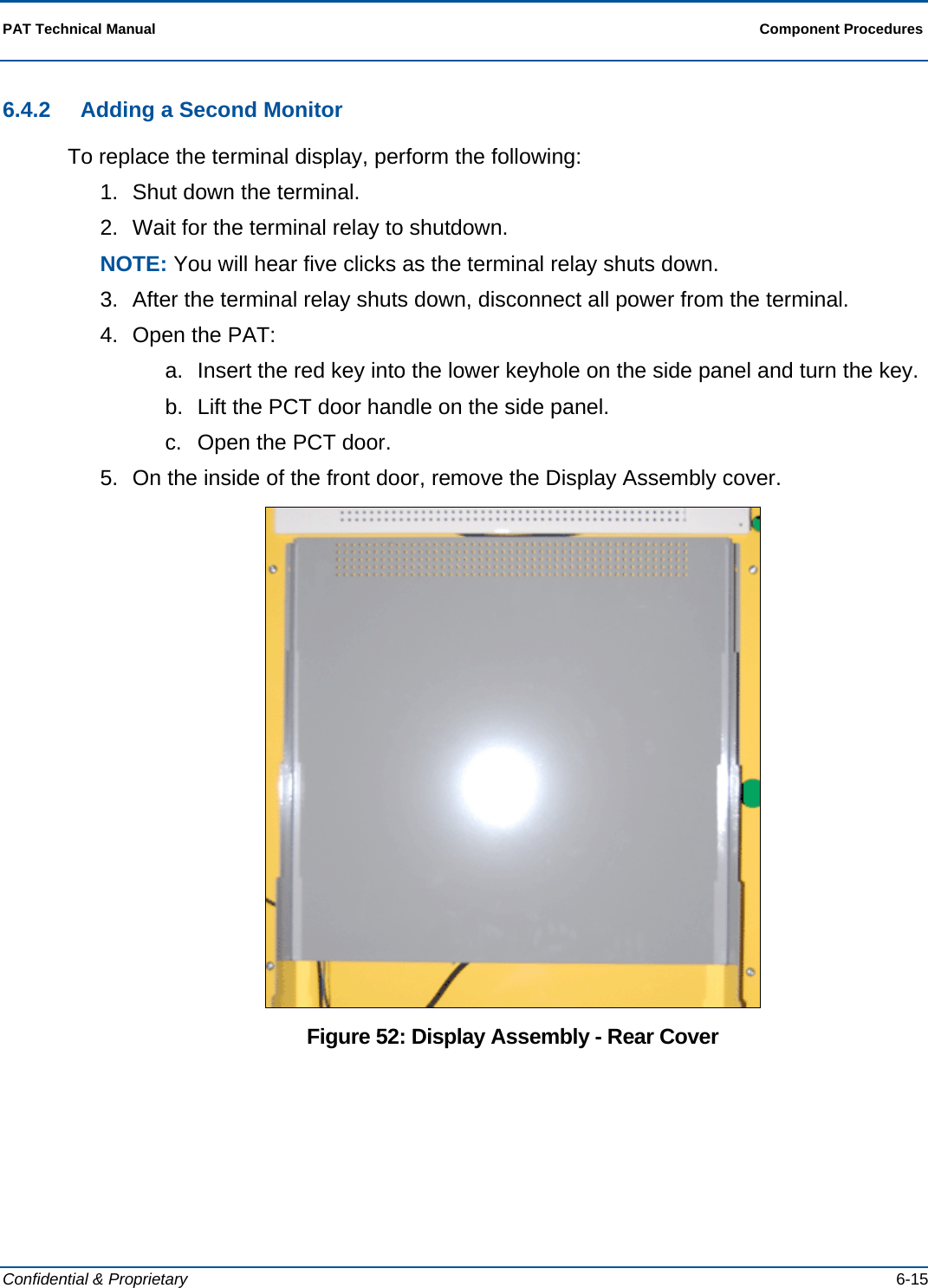
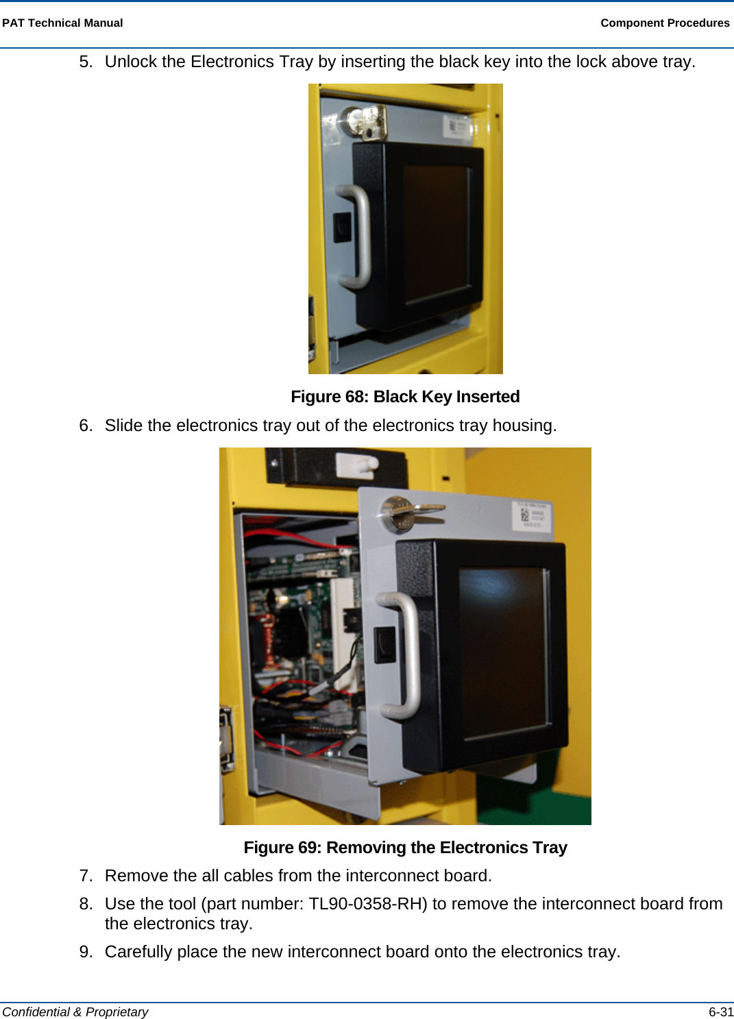
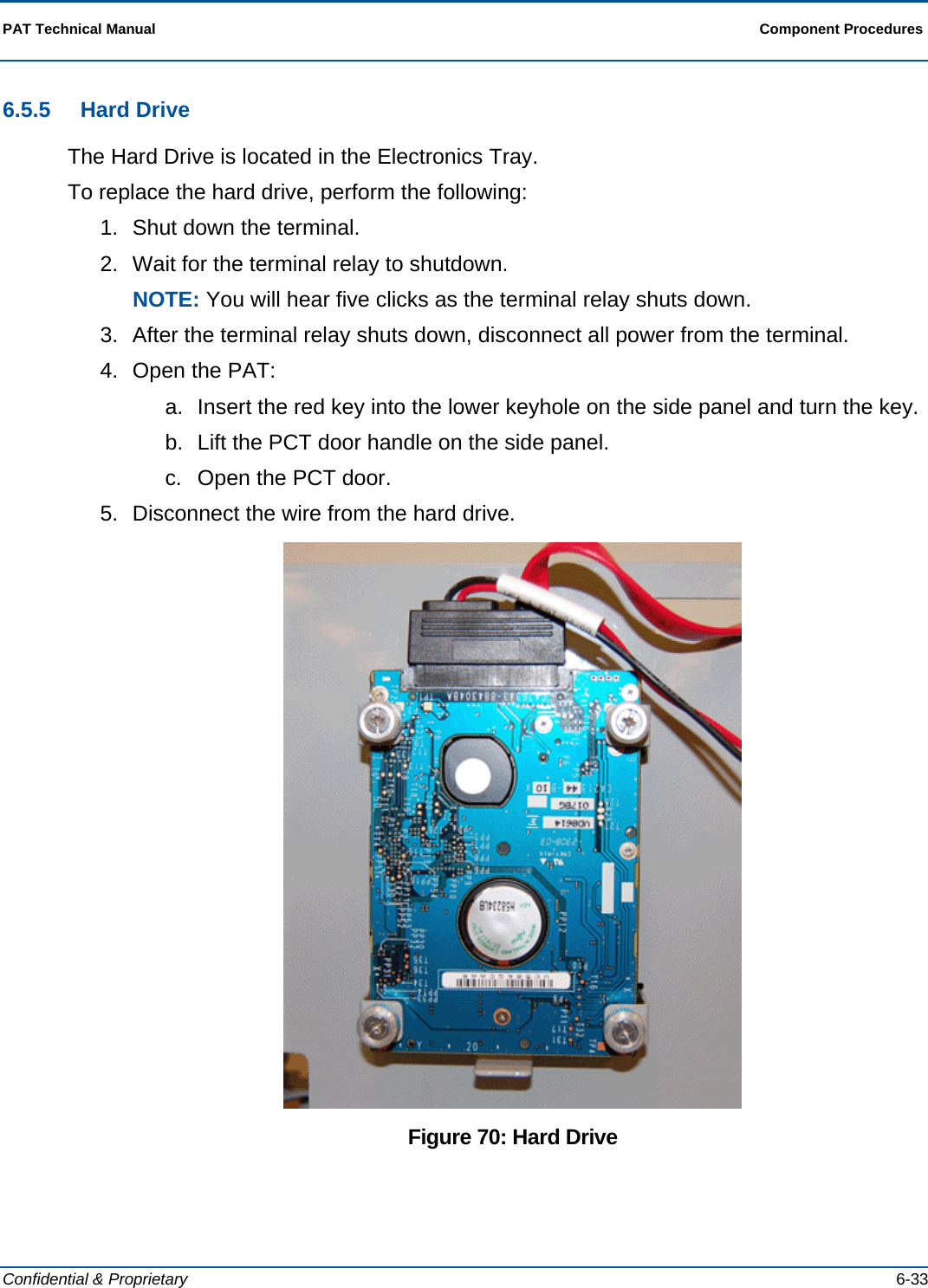
>
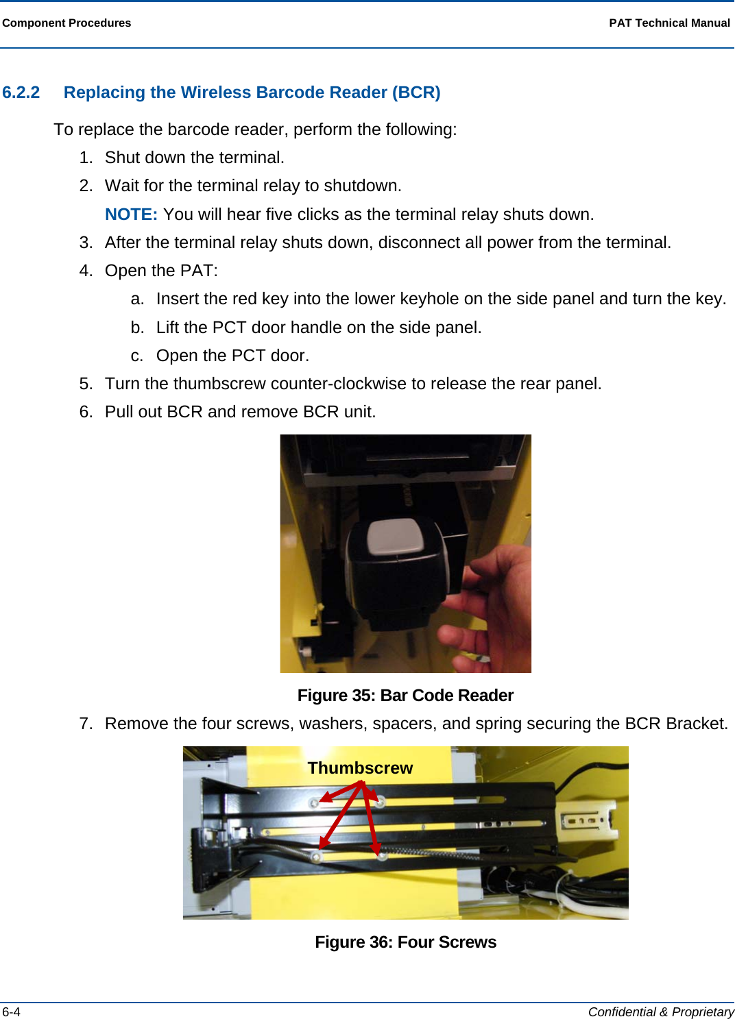
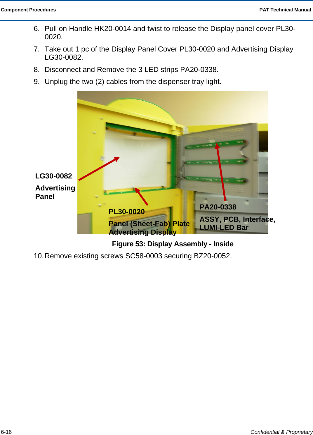
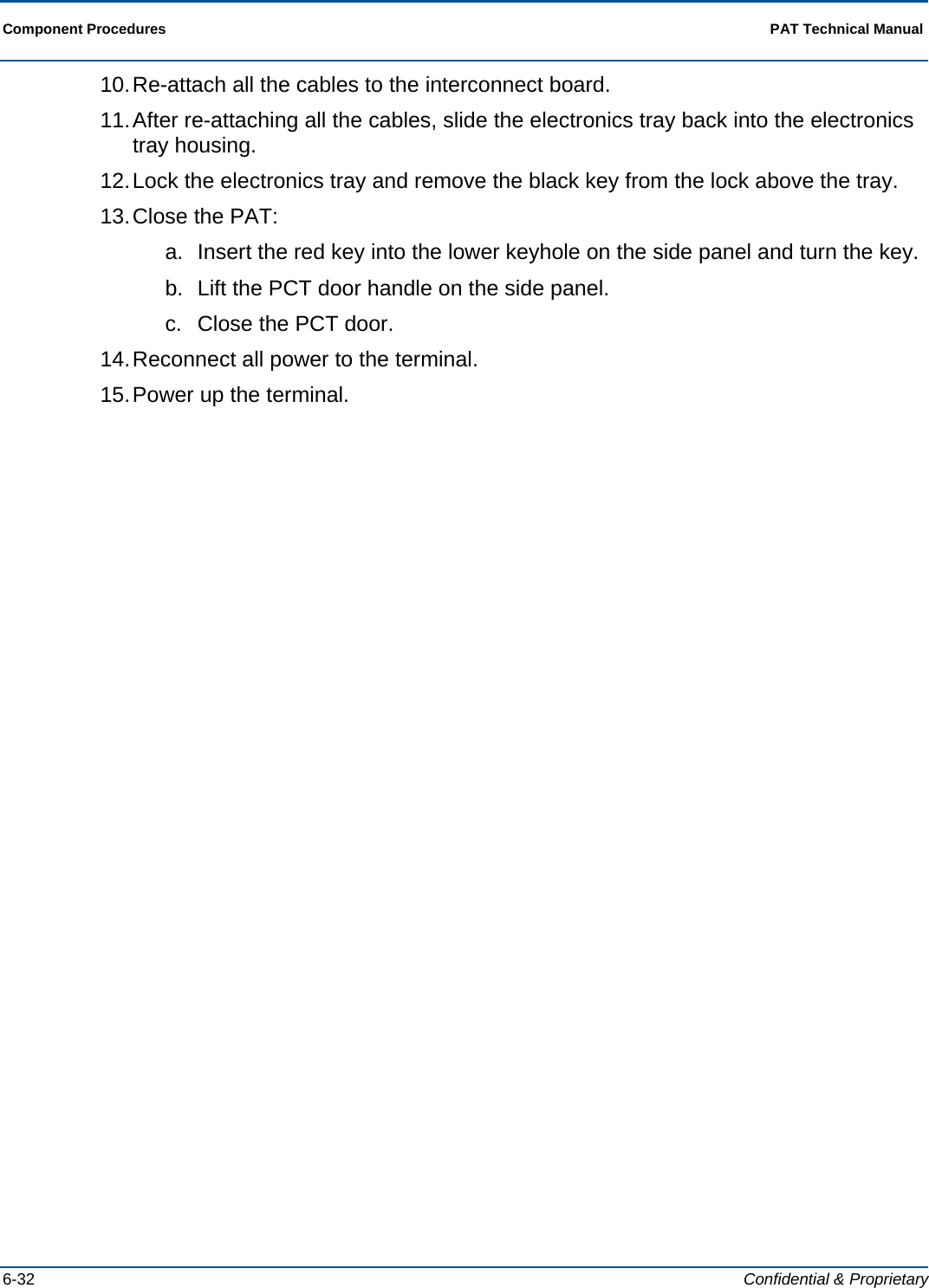
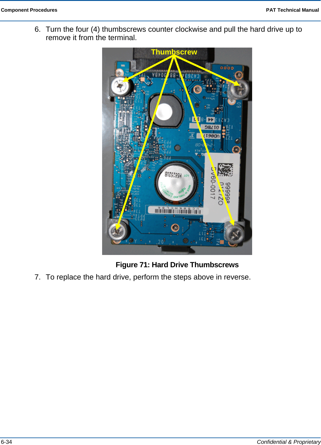
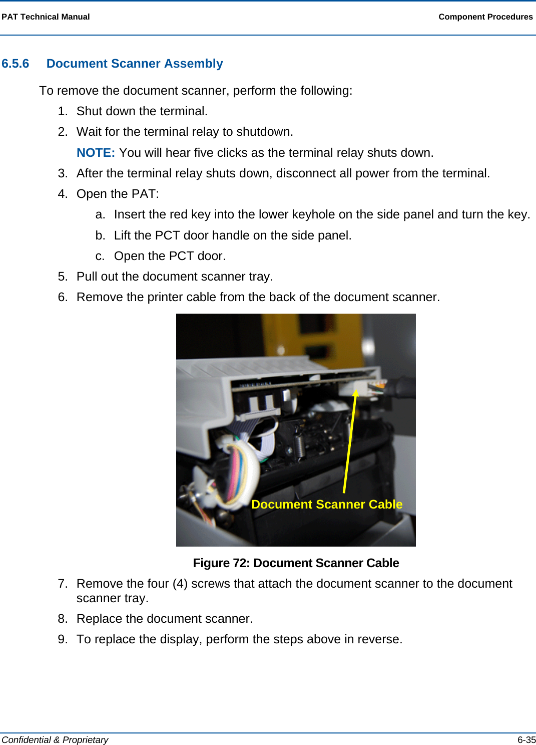
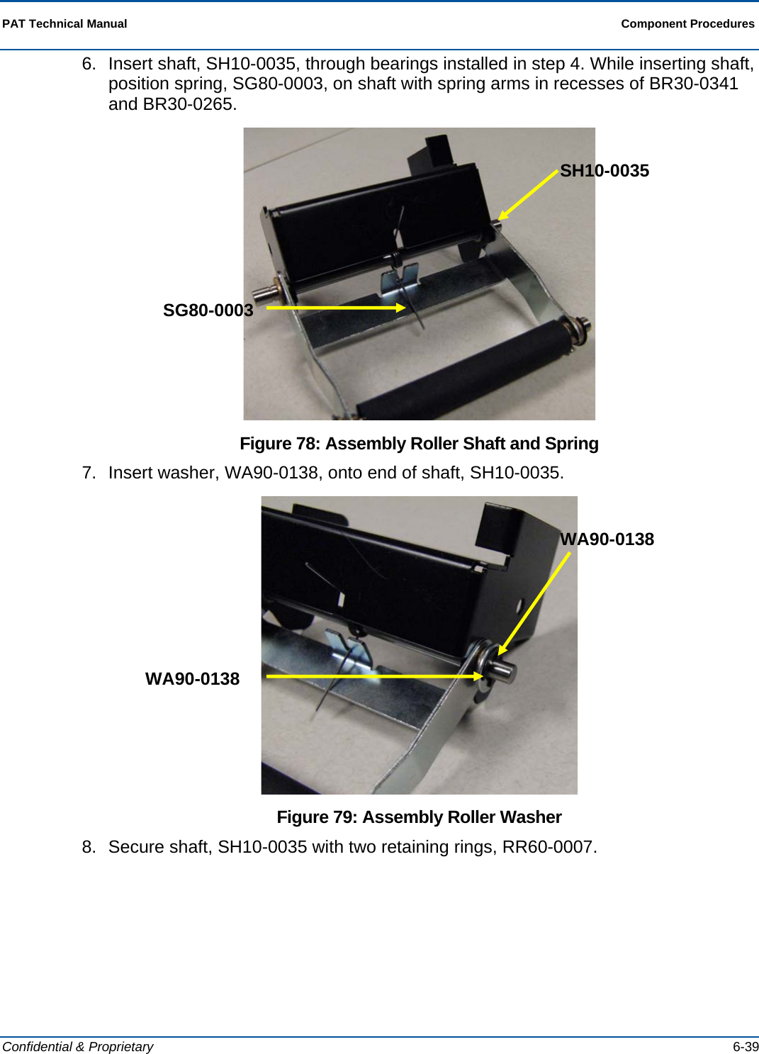
ITVM01 User Manual
Users Manual
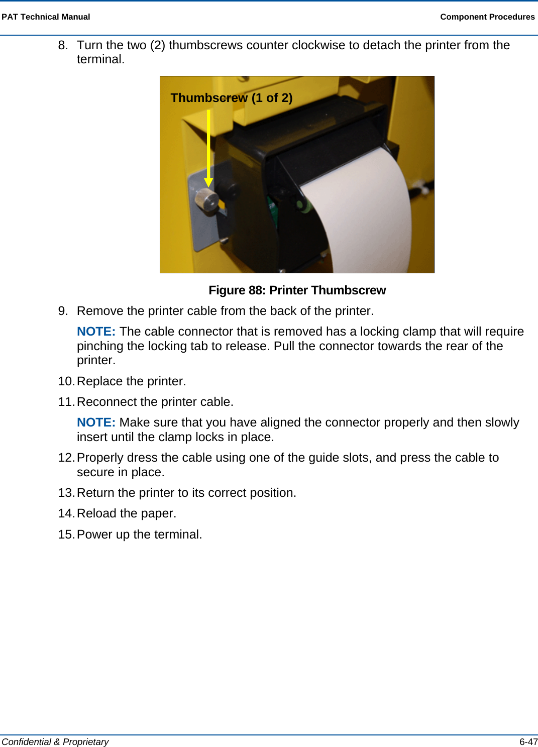
Navigation menu
Upload a User Manual
Namespaces
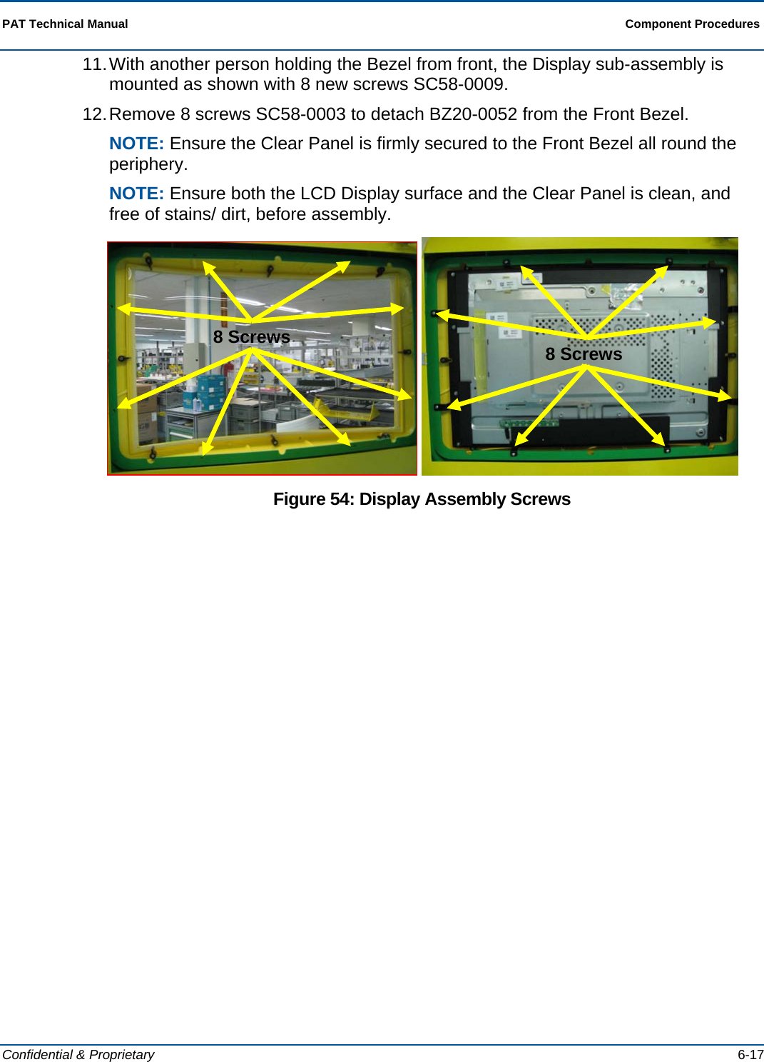
Wiki Guide
HTML
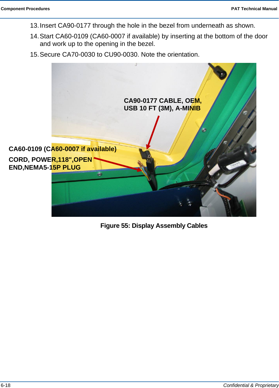
PDF
Info
Views
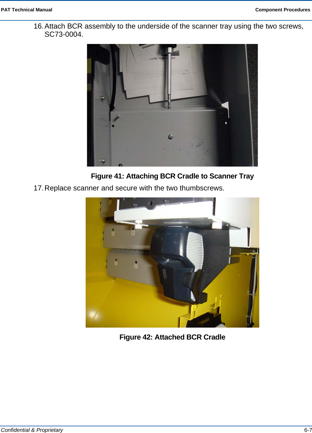
User Manual
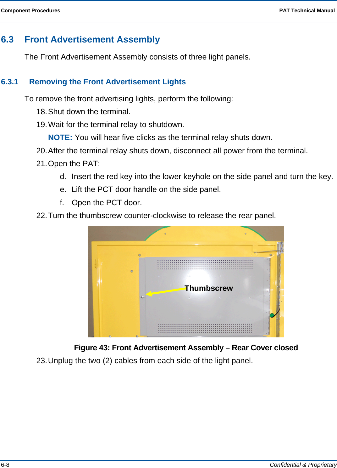
Discussion / Help
Navigation


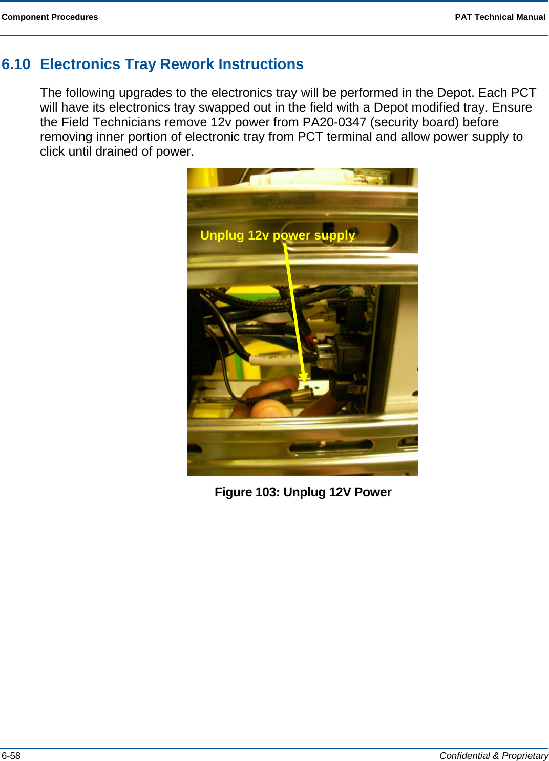
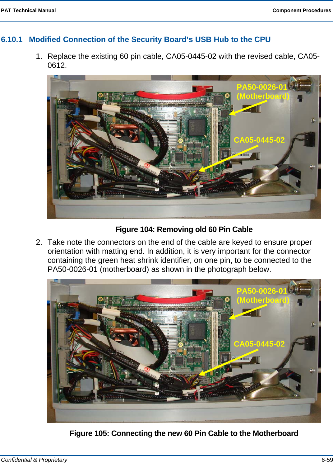
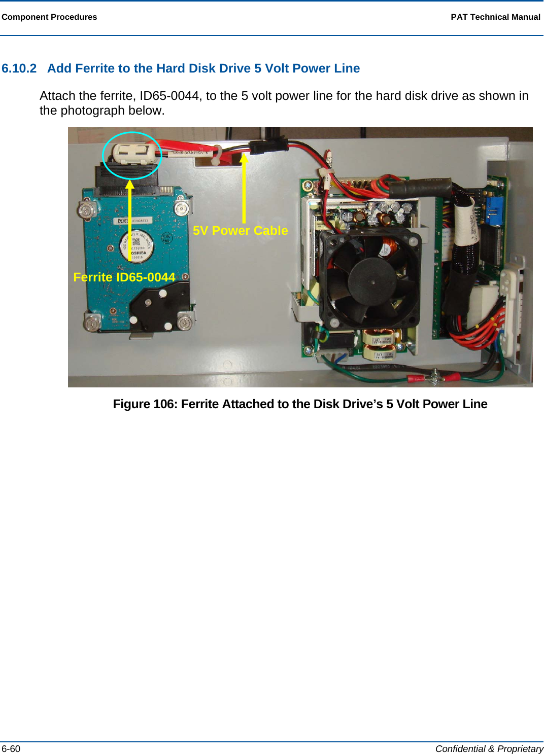
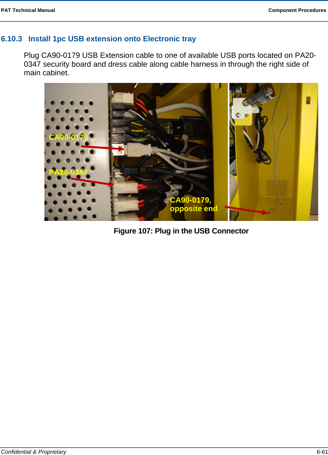
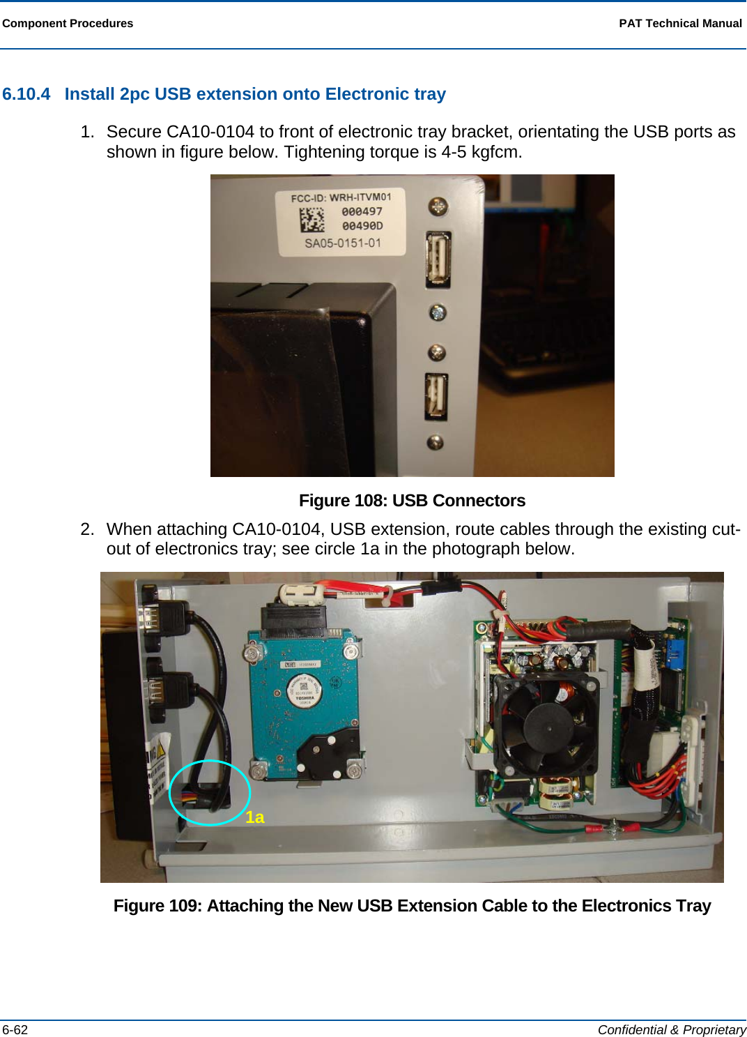
![Installation Procedures PAT Technical Manual 3-2 Confidential & Proprietary 3.2 Accessing the Master Link Operating System Prior to performing the PCT configuration, the installer must verify and record all information off the old PCT terminal. This is required to ensure that the new terminal is configured the same as the old terminal. To access this information, you will need to power up the old PCT and access the tech diagnostic. Next you have to enter the communications configuration screen and record the information listed in the top of the display. 3.3 Accessing the Aegis Operating System NOTE: The terminal will boot-up into the Master Link operating system. The steps below will guide you through the process of entering the Aegis operating system for the communication configuration procedure: 1. Power on the terminal: a. UPS on/off switch b. Terminal on/off switch 2. Connect the USB keyboard to the USB ports located on the underside of the electronic drawer. 3. Press [F9] on the keyboard. This will close out the Master Link application and open the windows desk top. 4. Locate and select the icon labeled “Phase2”. This will launch the Aegis software](https://usermanual.wiki/Scientific-Games/ITVM01/User-Guide-1644109-Page-44.png)
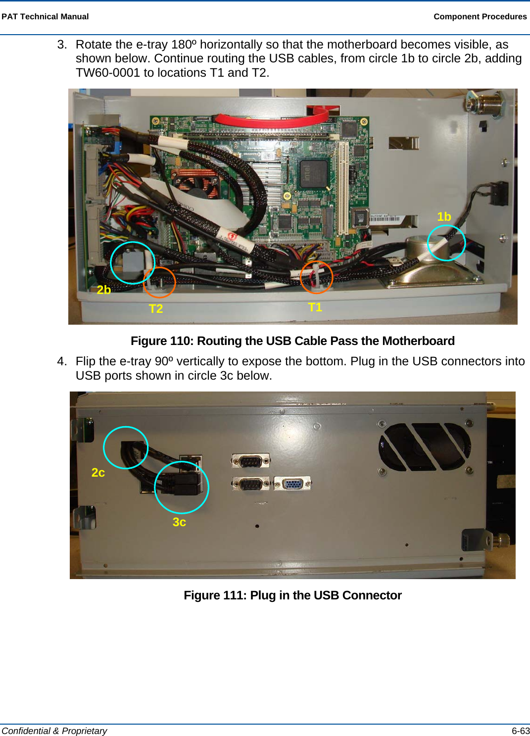
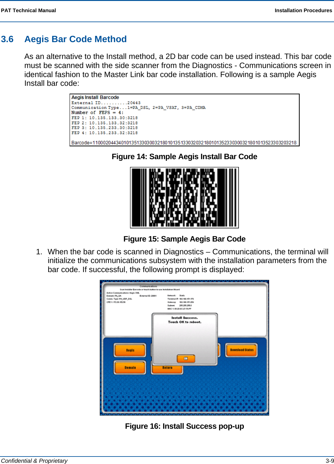
![Installation Procedures PAT Technical Manual 3-4 Confidential & Proprietary 3.5 Installation Wizard Once the terminal completes the reboot, repeat the steps in the Accessing the Master Link Operating System section. After touching the “Aegis” button, answer the following prompts as the Installation Wizard guides you through installation: 1. Enter the CFE IP address and touch [OK]. Figure 4: Enter CFE IP address pop-up](https://usermanual.wiki/Scientific-Games/ITVM01/User-Guide-1644109-Page-46.png)
![PAT Technical Manual Installation Procedures Confidential & Proprietary 3-5 2. Touch [Yes] and repeat the previous step until all CFE IP addresses have been entered. When all CFEs have been entered, touch [No]. NOTE: Up to 12 CFE IP addresses can be entered. Figure 5: Enter another CFE IP address pop-up 3. Touch the Device Group that is the correct communications type for your retailer. If you do not see the correct device group, touch [NEXT] to display the second page of Device Groups. Figure 6: Device Group page 1 pop-up](https://usermanual.wiki/Scientific-Games/ITVM01/User-Guide-1644109-Page-47.png)
![Installation Procedures PAT Technical Manual 3-6 Confidential & Proprietary Figure 7: Device Group page 2 pop-up 4. If the Installation is successful, the Install Successful pop-up displays. Figure 8: Install Successful pop-up 5. To use the new installation parameters, press [OK] to reboot the terminal.](https://usermanual.wiki/Scientific-Games/ITVM01/User-Guide-1644109-Page-48.png)
![PAT Technical Manual Installation Procedures Confidential & Proprietary 3-7 6. When the installation succeeds, the Summary Screen shows the DLS IP addresses and ports that were installed. Figure 9: Summary Screen 7. Touch [Set External Id] to display the following pop-up. Figure 10: Scan or External Id pop-up](https://usermanual.wiki/Scientific-Games/ITVM01/User-Guide-1644109-Page-49.png)
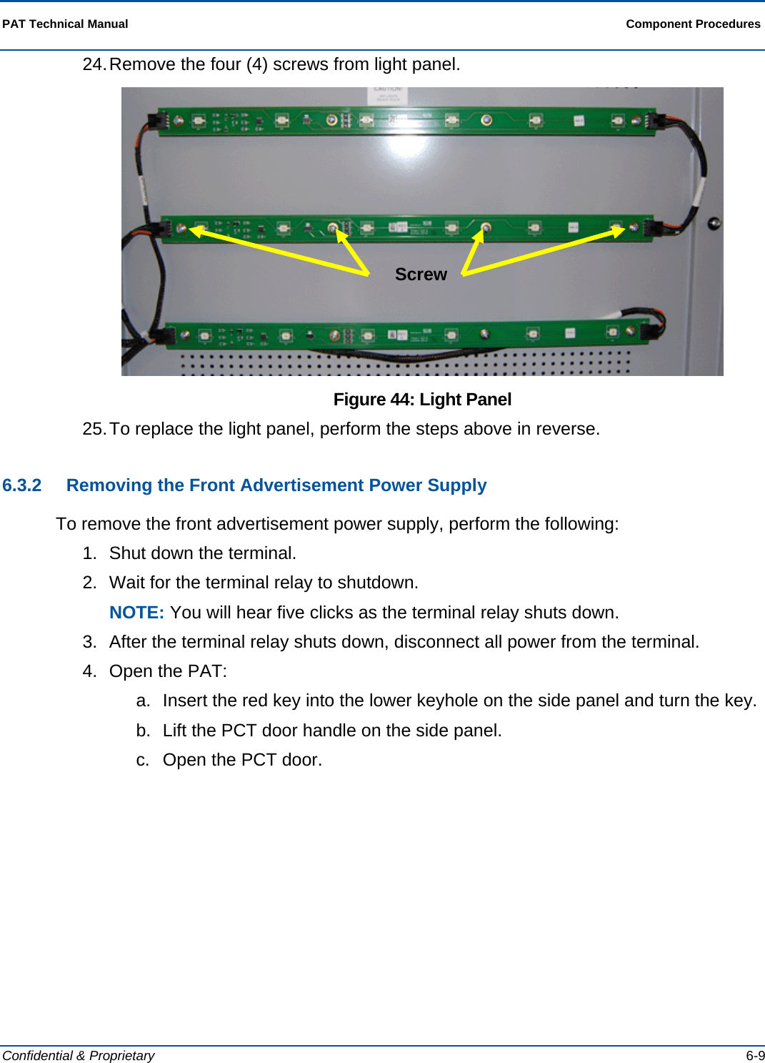
![Installation Procedures PAT Technical Manual 3-8 Confidential & Proprietary 8. Either manually key in the last 5 digits of the 12-digit terminal serial number on the side/rear of the terminal or use the wireless barcode reader to scan the terminal serial barcode to enter the External ID. Example: Figure 11: Sample External ID 9. Touch [Domain] to modify the domain, if necessary. Figure 12: Modify Domain pop-up 10. The final step of the installation involves pressing the [MAC Install] button. See the Aegis document regarding MAC Installation for more details. If successful, a pop-up displays “Success”. While the MAC transaction is being sent, the following pop-up is displayed: Figure 13: MAC Install Success pop-up](https://usermanual.wiki/Scientific-Games/ITVM01/User-Guide-1644109-Page-50.png)
![Installation Procedures PAT Technical Manual 3-10 Confidential & Proprietary 2. After the reboot, the FE should wait 2-3 minutes for the terminal to automatically sign on, and then print a host report, to confirm connectivity. Online games should appear on the main as well. 3. Touch [Set External Id] to display the following pop-up to enter this value. 4. Use the wireless bar code reader to scan the serial number bar code on the back of the terminal. Figure 17: Sample External ID 5. The final step of the installation involves pressing the [MAC Install] button. See the Aegis document regarding MAC Installation for more details. If successful, a pop-up displays “Success”. While the MAC transaction is being sent, the following pop-up is displayed: Figure 18: MAC Install Success pop-up](https://usermanual.wiki/Scientific-Games/ITVM01/User-Guide-1644109-Page-52.png)
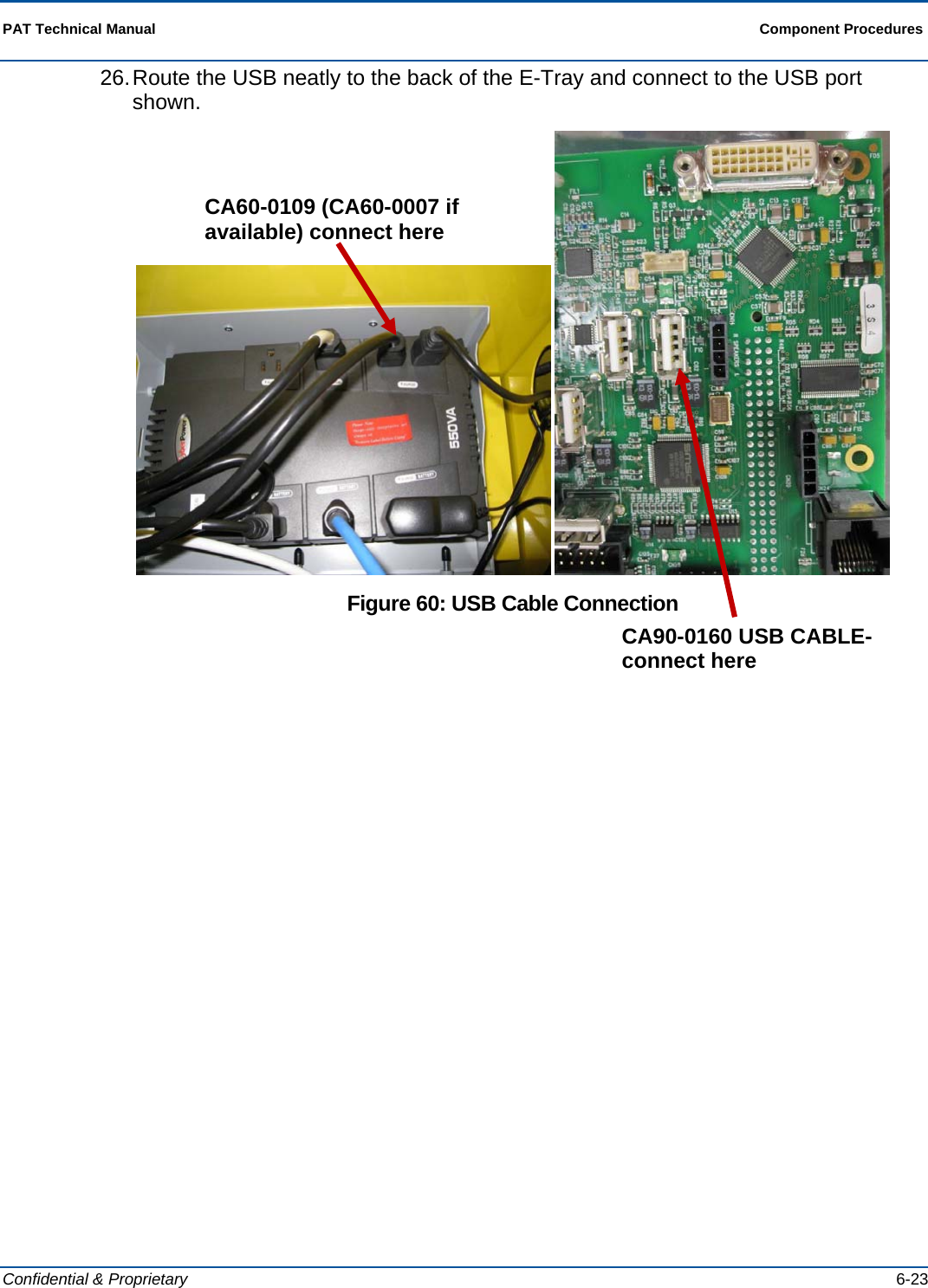
![PAT Technical Manual Installation Procedures Confidential & Proprietary 3-11 3.7 Configure PCT Communications 1. Allow the terminal to fully boot into the application. 2. Open front door or turn the red dotted key and login using 911911. 3. Make sure paper is loaded in the terminal printer. 4. Touch [Comm Diags]. 5. Touch [Network Config]. 6. Touch [FEP List]. 7. Remove any existing FEP’s from the software using the [Remove FEP] button. 8. Touch [Add FEP]. 9. Key in appropriate Primary FEP address. • 192.168.140.37 10. Key in appropriate port number. • 5400 11. Key in appropriate Secondary FEP addresses. • 192.168.140.38 • 192.168.141.37 • 192.168.141.38 12. Key in appropriate port number. • 5400 13. Touch [Network Config]. 14. Touch [Setup Retailer]. 15. Key in the appropriate jurisdiction number (123). 16. Key in the appropriate line number, and touch [OK]. 17. Key in the appropriate poll number, and touch [OK]. 18. Key in Installer BC, and touch [OK] - (0016327318313854778198) 19. Key in Installer ID, and touch [OK] - (1) 20. Key in Installer PW, and touch [OK] - (778198) 21. Key in Retailer PRN, and touch [OK]. 22. Key in Retailer PW, and touch [OK]. 23. Key in Installer WO, and touch [OK] - (0000016601)](https://usermanual.wiki/Scientific-Games/ITVM01/User-Guide-1644109-Page-53.png)
![Installation Procedures PAT Technical Manual 3-12 Confidential & Proprietary 24. Touch [Install]. If properly configured and connected you will get an Installation Successful message. 25. After the “Successful Install” message displays, touch [Return to Main Menu]. 26. Touch [Tech Functions]. 27. Set Password One (1) (Initial Retailers password (IRP)). 28. Set Password Two (add 222222’s). 29. Set Machines ID (machine ID equals the terminals serial number but drop the zero).](https://usermanual.wiki/Scientific-Games/ITVM01/User-Guide-1644109-Page-54.png)
![Installation Procedures PAT Technical Manual 3-14 Confidential & Proprietary 3.9 Pinging Process 1. Connect keyboard to the USB port on the underside of the electronic tray. 2. Press <F9>. This will close out the running application and bring you into windows. 3. Press/Select <CTRL>, <ALT> & <DELETE> at the same time. 4. Select [Task Manager]. Figure 19: Windows Task Manager screen 5. Select [New Task]. Figure 20: Create New Task pop-up](https://usermanual.wiki/Scientific-Games/ITVM01/User-Guide-1644109-Page-56.png)
![PAT Technical Manual Installation Procedures Confidential & Proprietary 3-15 6. Type cmd and press [OK]. This opens the command screen. Figure 21: Task Manager Screen 7. At the prompt, type the following: [ping(sp)IP number] and select <RETURN>. Example: c:\Documents and Settings> ping 10.117.168.65 8. Verify that you received a return message indicating a successful ping.](https://usermanual.wiki/Scientific-Games/ITVM01/User-Guide-1644109-Page-57.png)
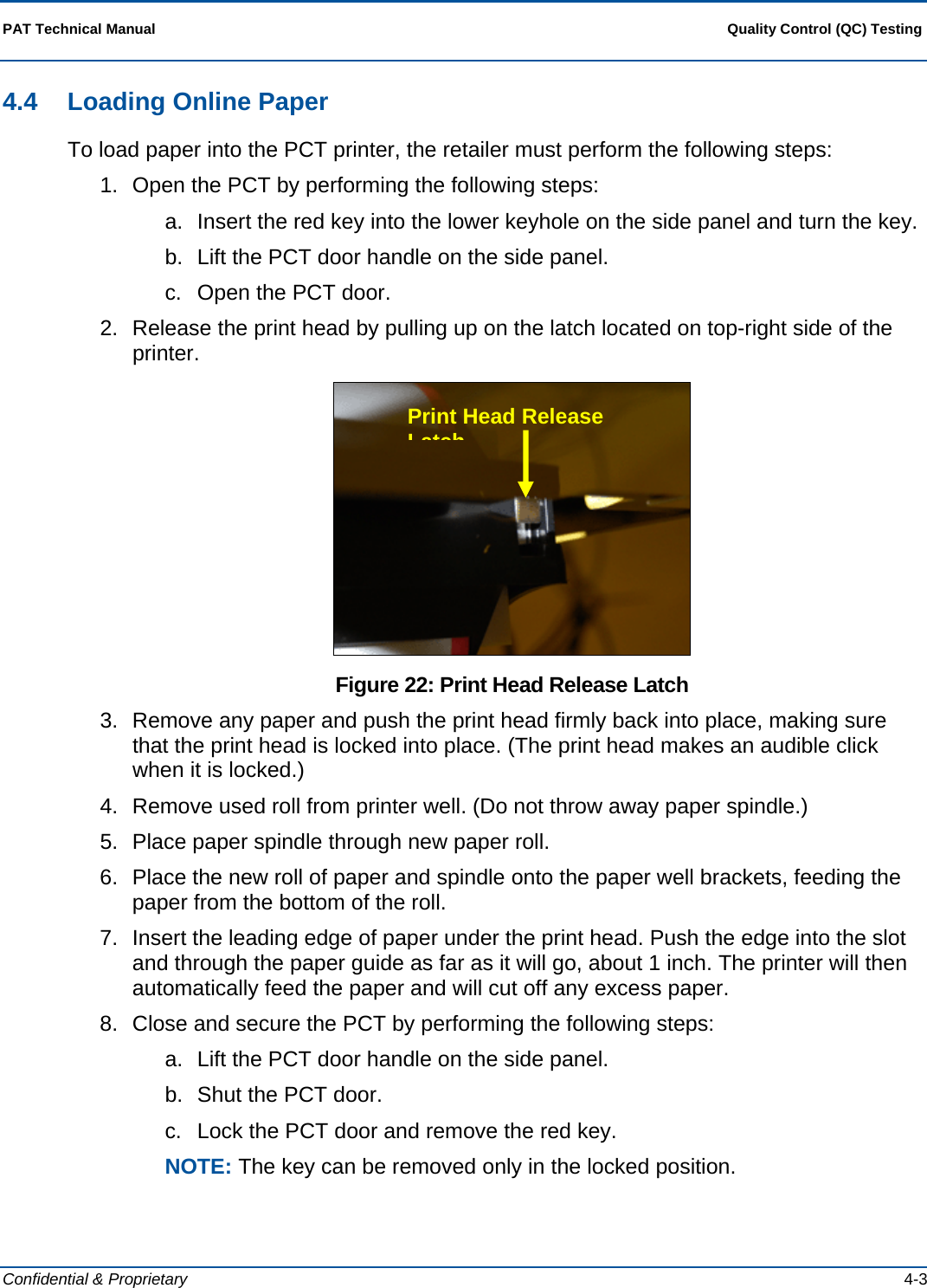
![Quality Control (QC) Testing PAT Technical Manual 4-4 Confidential & Proprietary 4.5 Loading Instant Tickets Perform the following steps to load paper into the printer. 1. Insert the blue key into the top barrel lock and turn the key. 2. Touch [Burster Status]. 3. Touch the green [Load Pack] button for the empty dispenser. 4. On the pop-up screen, scan or enter the game or pack number. 5. Either scan the Pack Activity Card, scan the instant ticket validation barcode, or manually enter the game/pack number. 6. After the game/pack number displays, touch [OK]. 7. Touch [YES] to load a pull pack or [NO] to load a partial pack. If loading a full pack, go to step 10 8. Enter the starting ticket and touch [OK]. 9. Enter the ending ticket and touch [OK]. 10. Open the drawer and insert the lowest numbered ticket into the burster. Figure 23: Inserting Instant Tickets into Burster 11. If the ticket is loaded correctly, the “Successfully Loaded” message pop-up displays. 12. Touch [OK] and close the drawer.](https://usermanual.wiki/Scientific-Games/ITVM01/User-Guide-1644109-Page-62.png)
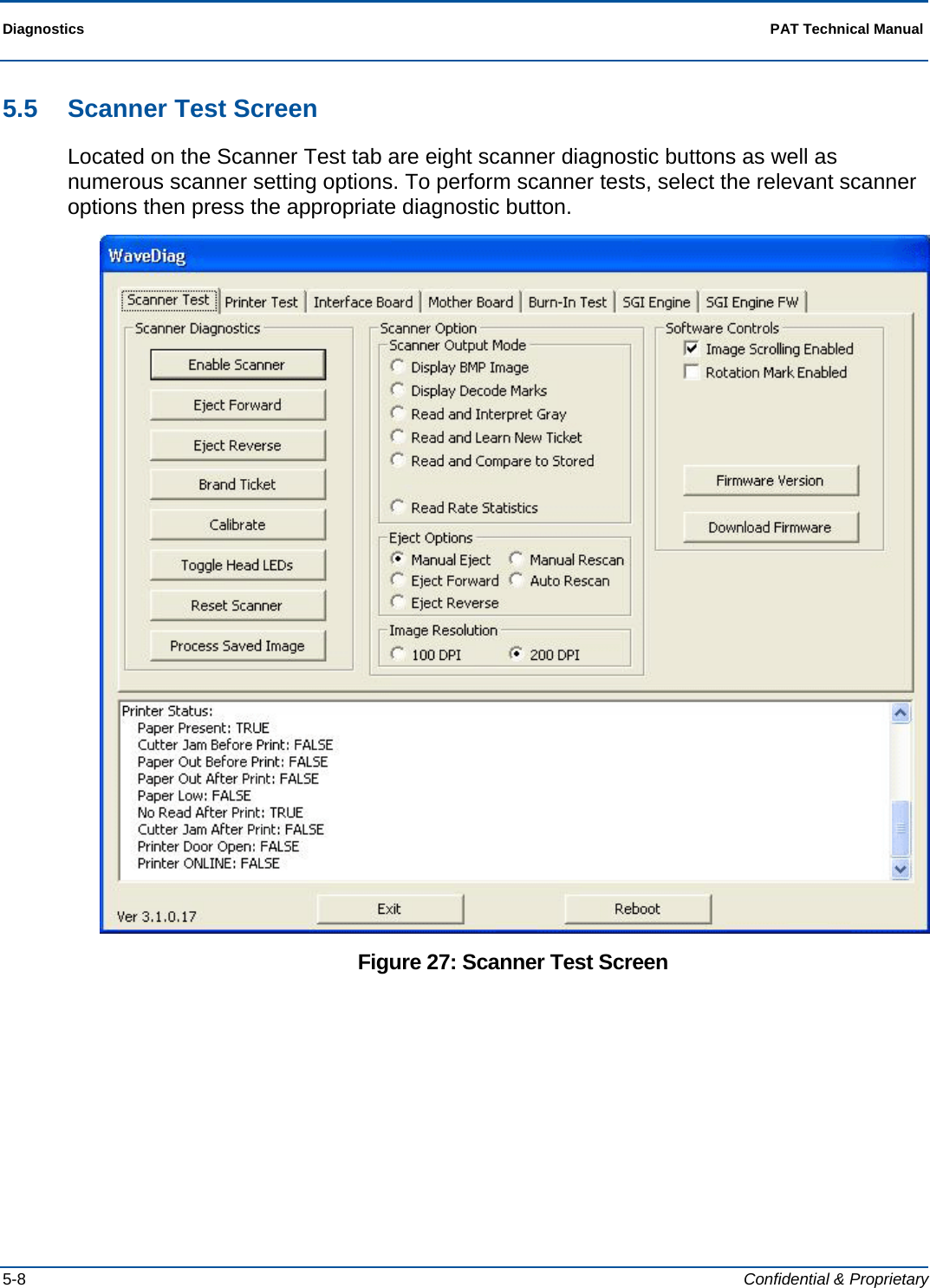
![PAT Technical Manual Diagnostics Confidential & Proprietary 5-9 5.5.1 Scanner Diagnostics The following selections are provided in the Scanner Diagnostics area of the Scanner Test tab: 5.5.1.1 Enable Scanner Description Select this option to activate the scanner. When this option is selected, the scanner will accept items for scanning. Preconditions Unit must be operational. Starting the Test Select [Enable Scanner] from the Scanner Diagnostics area. Flow When this option is selected the scanner becomes active and will accept items for feeding. Ending the Test DNA Analyzing Test Results The scanner should accept an item for feeding. If the scanner accepts the item, this diagnostic is considered to be successful. Exceptions Scanner does not accept item for feeding Corrective Actions Make sure Enable Scanner is selected and item properly fed.](https://usermanual.wiki/Scientific-Games/ITVM01/User-Guide-1644109-Page-73.png)
![Diagnostics PAT Technical Manual 5-10 Confidential & Proprietary 5.5.1.2 Eject Forward Description Select this item to eject any item in the scanner drive in a forward direction. Preconditions Unit must be operational. Starting the Test Select [Eject Forward] from the Scanner Diagnostics area. Flow When this option is selected the scanner ejects any item in the scanner drive in a forward direction. If no item is currently in the scanner drive, the drive mechanism operates for approximately one second. After this interval a new item may be fed into the scanner. Ending the Test The test ends automatically. Analyzing Test Results If the scanner ejects the item in the drive or is heard to be operating if no item is in the drive, the test is successful. Exceptions Scanner does not operate/eject item. Corrective Actions Make sure item in drive is not jammed. NOTE: Even if item is jammed, the drive mechanism should be heard to operate.](https://usermanual.wiki/Scientific-Games/ITVM01/User-Guide-1644109-Page-74.png)
![PAT Technical Manual Diagnostics Confidential & Proprietary 5-11 5.5.1.3 Eject Reverse Description Select this item to eject any item in the scanner drive in a backward direction. Preconditions Unit must be operational. Starting the Test Select [Eject Reverse] from the Scanner Diagnostics area. Flow When this option is selected the scanner ejects any item in the scanner drive in a backward direction. If no item is currently in the scanner drive, the drive mechanism operates for approximately one second. After this interval a new item may be fed into the scanner. Ending the Test The test ends automatically. Analyzing Test Results If the scanner ejects the item in the drive or is heard to be operating if no item is in the drive, the test is successful. Exceptions Scanner does not operate/eject item. Corrective Actions Make sure item in drive is not jammed. NOTE: Even if item is jammed, the drive mechanism should be heard to operate. 5.5.1.4 Brand Ticket Description Select this button to brand a ticket. Preconditions Unit must be operational and scanner enabled. Eject option must be set to Manual Eject. Flow Feed ticket into scanner then select [Brand Ticket] from the Scanner Diagnostics area. The unit brands the ticket and displays the result in the message window at the bottom of the screen. Ending the Test The test ends automatically.](https://usermanual.wiki/Scientific-Games/ITVM01/User-Guide-1644109-Page-75.png)
![Diagnostics PAT Technical Manual 5-12 Confidential & Proprietary Analyzing Test Results The test is successful if the ticket is branded and the following message appears in the message box: Brand Status: Brand OK Exceptions Ticket is not branded. Brand Status: Brand OK message is not displayed. Corrective Actions DNA 5.5.1.5 Calibrate Description Select this button to calibrate the scanner. Preconditions Unit must be operational and scanner enabled. Flow Select [Calibrate] from the Scanner Diagnostics area and feed an 8 ½ X 4 inch piece of white paper into scanner. This procedure calibrates the distance between the paper source and the light source, providing a precise measurement between the two. Ending the Test The test ends automatically. Analyzing Test Results The test is successful if the ticket is branded and the following message appears in the message box: Brand Status: Brand OK Exceptions Ticket is not branded. Brand Status: Brand OK message is not displayed. Corrective Actions DNA 5.5.1.6 Toggle Head LEDs Description Select this button to toggle on and off Head LEDs. Preconditions Unit must be operational.](https://usermanual.wiki/Scientific-Games/ITVM01/User-Guide-1644109-Page-76.png)
![PAT Technical Manual Diagnostics Confidential & Proprietary 5-13 Flow Select [Toggle Head LEDs] from the Scanner Diagnostics area several times. Each time the button is selected the Head LEDs will alternately turn on and off. Ending the Test The test ends when the user stops selecting the related button. Analyzing Test Results The test is successful if Head LEDs turn on and off alternately with each button selection. Exceptions LEDs do not turn on and off as the Toggle Head LCDs button is selected. Corrective Actions DNA 5.5.1.7 Reset Scanner Description Select this button to reset the scanner Preconditions Unit must be operational. Flow Select [Reset Scanner] from the Scanner Diagnostics area. When selected, a reset command is sent to the scanner. Ending the Test The test ends automatically. Analyzing Test Results The test is successful if the scanner is reset. Exceptions Scanner is not reset. Corrective Actions DNA](https://usermanual.wiki/Scientific-Games/ITVM01/User-Guide-1644109-Page-77.png)
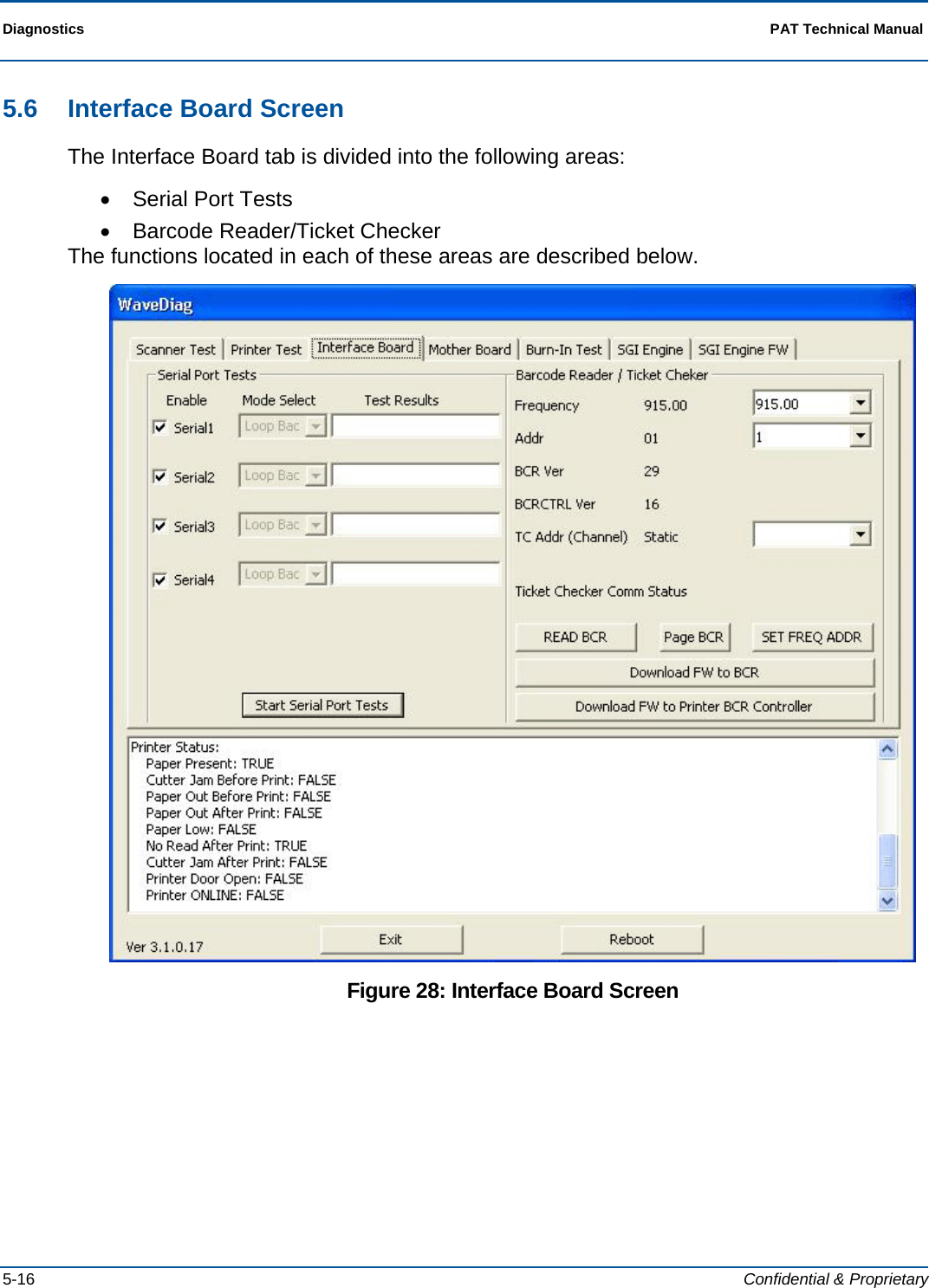
![PAT Technical Manual Diagnostics Confidential & Proprietary 5-17 5.6.1 Serial Port Tests The following selections are provided in the Serial Port Tests area of the Interface Board tab: 5.6.1.1 Serial Port Test Description Select this option to test the terminal’s serial ports. Preconditions Unit must be operational. A Serial Loopback connector must be attached to the port being tested. Starting the Test Select ports to test by placing a chicanery in the box next to each port to be tested. Select the relevant mode for each port by making a selection from the dropdown menu located next to each port. Select the [Start Serial Port Test] button to begin testing. Flow Once the testing has started, the result for each port is displayed in the Test Results box located next to each port. The ports are continually tested with the results being continually updated until the test is stopped by the user. Ending the Test Select the [Stop Serial Test] button ([Start] button now relabeled as [Stop]). Analyzing Test Results The number of passes and fails for each port are displayed in the Test Results boxes. Exceptions DNA Corrective Actions DNA](https://usermanual.wiki/Scientific-Games/ITVM01/User-Guide-1644109-Page-81.png)
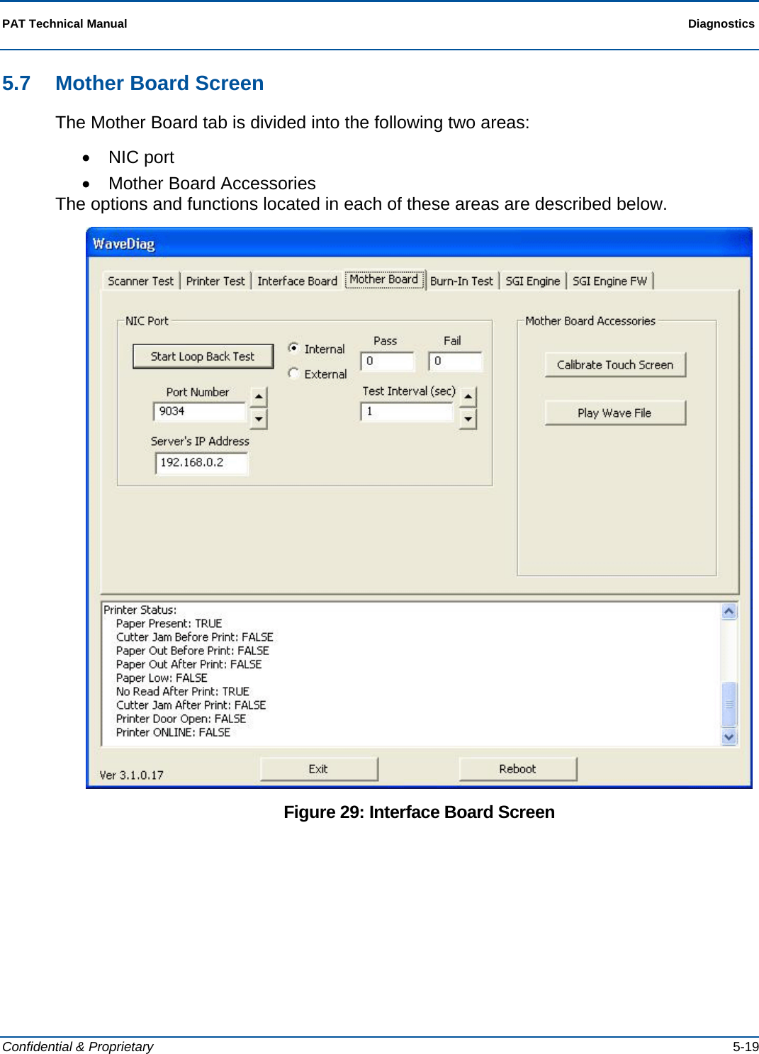
![Diagnostics PAT Technical Manual 5-20 Confidential & Proprietary 5.7.1 NIC Port The following selections are provided in the NIC Port area of the Mother Board tab: 5.7.1.1 Start Loop Back Test Description Select this option to test the NIC port. Preconditions Unit must be operational. Starting the Test Select internal or external. Use the up and down arrows to select the port number. Enter the relevant IP address in the Server’s IP Address field. Use the up and down arrow to enter the desired test interval in second in the Test Interval (sec) field. Value can be between 0 and 1000. Press the [Start Loop Back Test] button to begin testing. Flow Once the testing has started, the relevant port is continuously tested at the selected interval until the user stops the test. The results of the test are displayed in the Pass and Fail fields. Each test iteration increments the number in either the Pass or Fail field depending on the test result. Ending the Test Select the [Stop Loopback Test] button ([Start] button now relabeled as [Stop]). Analyzing Test Results The number of passes and fails are displayed in the Pass and Fail fields, respectively. Exceptions DNA Corrective Actions DNA Modem Port This area of the Motherboard tab allows the user to test the modem port.](https://usermanual.wiki/Scientific-Games/ITVM01/User-Guide-1644109-Page-84.png)
![PAT Technical Manual Diagnostics Confidential & Proprietary 5-21 5.7.2 Mother Board Accessories The following selections are provided in the Mother Board Accessories area of the Mother Board tab: 5.7.2.1 Calibrate Touch Screen When selected launches the Touch Screen Calibration program. 5.7.2.2 Play Wave File Description Select this option to test the wave file. Preconditions Unit must be operational. Starting the Test Select Play Wave File from the Mother Board Accessories area. Flow After each successive selection of this button, the wave file plays. Ending the Test The test ends when the user stops pressing [Play Wave File]. Analyzing Test Results The test is successful if the wave file plays when [Play Wave File] is selected. Exceptions Wave file does not play. Corrective Actions DNA](https://usermanual.wiki/Scientific-Games/ITVM01/User-Guide-1644109-Page-85.png)
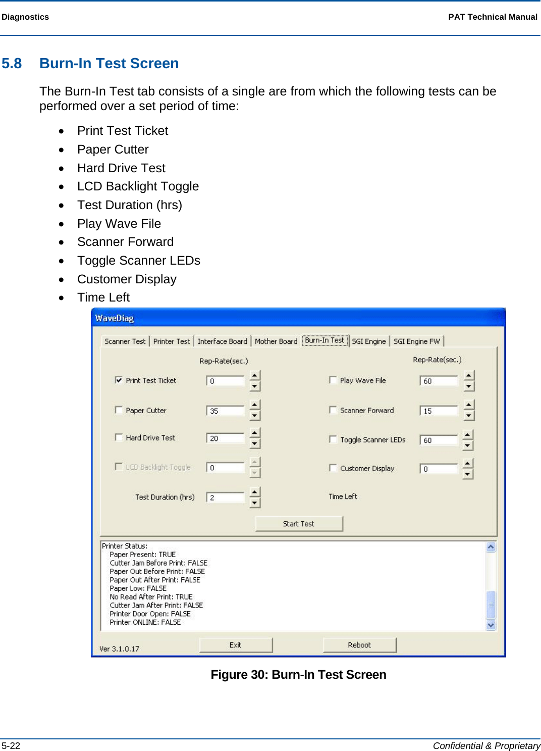
![PAT Technical Manual Diagnostics Confidential & Proprietary 5-23 5.8.1 Burn-In Tests The tests contained on the Burn-In Test tab can be performed simultaneously in any combination, with the repetition rate for each test being set independently from zero to 10,000 seconds. The tests and related options are described below. 5.8.1.1 Print Test Ticket Description Select this option to print test tickets. Preconditions Unit must be operational. Starting the Test 1. Select test to be performed by checking the box next to test. 2. Set the repetition rate for the test. The repetition rate is given in seconds and must be between 0 and 10,000. 3. Set the test duration. The duration is set in hours and must be between 0 and 10,000. 4. Press the [Start Test] button to begin testing. NOTE: If test duration is set to 0, the system will immediately indicate that the test is complete, even though no testing is performed. Flow Once the test is started, the system performs the selected test at the set repetition rate for the selected number of hours or until the user stops the manually. Ending the Test The test ends when the entered test duration has expired or when the user selects the [Stop Test] button ([Start] button now relabeled as [Stop]) Analyzing Test Results Verify that the ticket prints at the selected rate. Exceptions None Corrective Actions None](https://usermanual.wiki/Scientific-Games/ITVM01/User-Guide-1644109-Page-87.png)
![Diagnostics PAT Technical Manual 5-24 Confidential & Proprietary 5.8.1.2 Paper Cutter Description Select this option to test the paper cutter. For each repetition of the test, paper is advanced and cut. Preconditions Unit must be operational. Starting the Test 1. Select test to be performed by checking the box next to test. 2. Set the repetition rate for the test. The repetition rate is given in seconds and must be between 0 and 10,000. 3. Set the test duration. The duration is set in hours and must be between 0 and 10,000. 4. Press the [Start Test] button to begin testing. NOTE: If test duration is set to 0, the system will immediately indicate that the test is complete, even though no testing is performed. Flow Once the test is started, the system performs the selected test at the set repetition rate for the selected number of hours or until the user stops the manually. Ending the Test The test ends when the entered test duration has expired or when the user selects the [Stop Test] button ([Start] button now relabeled as [Stop]). Analyzing Test Results Verify that cutter cycles at the selected rate. Exceptions DNA Corrective Actions DNA](https://usermanual.wiki/Scientific-Games/ITVM01/User-Guide-1644109-Page-88.png)
![PAT Technical Manual Diagnostics Confidential & Proprietary 5-25 5.8.1.3 Hard Drive Test Description Select this option to test the hard drive. Preconditions Unit must be operational. Starting the Test 1. Select test to be performed by checking the box next to test. 2. Set the repetition rate for the test. The repetition rate is given in seconds and must be between 0 and 10,000. 3. Set the test duration. The duration is set in hours and must be between 0 and 10,000. 4. Press the [Start Test] button to begin testing. NOTE: If test duration is set to 0, the system will immediately indicate that the test is complete, even though no testing is performed. Flow Once the test is started, the system performs the selected test at the set repetition rate for the selected number of hours or until the user stops the manually. Ending the Test The test ends when the entered test duration has expired or when the user selects the [Stop Test] button ([Start] button now relabeled as [Stop]). Analyzing Test Results DNA Exceptions DNA Corrective Actions DNA](https://usermanual.wiki/Scientific-Games/ITVM01/User-Guide-1644109-Page-89.png)
![Diagnostics PAT Technical Manual 5-26 Confidential & Proprietary 5.8.1.4 LCD Backlight Toggle Description Select this option to test LCD backlight. Preconditions Unit must be operational. Starting the Test 1. Select test to be performed by checking the box next to test. 2. Set the repetition rate for the test. The repetition rate is given in seconds and must be between 0 and 10,000. 3. Set the test duration. The duration is set in hours and must be between 0 and 10,000. 4. Press the [Start Test] button to begin testing. NOTE: If test duration is set to 0, the system will immediately indicate that the test is complete, even though no testing is performed. Flow Once the test is started, the system performs the selected test at the set repetition rate for the selected number of hours or until the user stops the manually. Ending the Test The test ends when the entered test duration has expired or when the user selects the [Stop Test] button ([Start] button now relabeled as [Stop]). Analyzing Test Results Test is successful, if backlight toggle action operates. Exceptions Light toggle action does not operate. Corrective Actions DNA Test Duration Set the amount of time selected for the duration of the test. Play Wave File Set the amount of time the wave file is to be played.](https://usermanual.wiki/Scientific-Games/ITVM01/User-Guide-1644109-Page-90.png)
![PAT Technical Manual Diagnostics Confidential & Proprietary 5-27 5.8.1.5 Scanner Forward Description Select this option to test the scanner operation in a forward direction. Preconditions Unit must be operational. Starting the Test 1. Select test to be performed by checking the box next to test. 2. Set the repetition rate for the test. The repetition rate is given in seconds and must be between 0 and 10,000. 3. Set the test duration. The duration is set in hours and must be between 0 and 10,000. 4. Press the [Start Test] button to begin testing. NOTE: If test duration is set to 0, the system will immediately indicate that the test is complete, even though no testing is performed. Flow Once the test is started, the system performs the selected test at the set repetition rate for the selected number of hours or until the user stops the manually. Ending the Test The test ends when the entered test duration has expired or when the user selects the [Stop Test] button ([Start] button now relabeled as [Stop]). Analyzing Test Results The test is successful, if the item is scanned. Exceptions Item is not scanned. Corrective Actions DNA](https://usermanual.wiki/Scientific-Games/ITVM01/User-Guide-1644109-Page-91.png)
![Diagnostics PAT Technical Manual 5-28 Confidential & Proprietary 5.8.1.6 Toggle Scanner LEDs Description Select this option to test the scanner LEDs. Preconditions Unit must be operational. Starting the Test 1. Select test to be performed by checking the box next to test. 2. Set the repetition rate for the test. The repetition rate is given in seconds and must be between 0 and 10,000. 3. Set the test duration. The duration is set in hours and must be between 0 and 10,000. 4. Press the [Start Test] button to begin testing. NOTE: If test duration is set to 0, the system will immediately indicate that the test is complete, even though no testing is performed. Flow Once the test is started, the system performs the selected test at the set repetition rate for the selected number of hours or until the user stops the manually. Ending the Test The test ends when the entered test duration has expired or when the user selects the [Stop Test] button ([Start] button now relabeled as [Stop]). Analyzing Test Results The test is successful, if the scanner LED toggle action operates. Exceptions LED toggle action does not operate. Corrective Actions DNA Customer Display Set the amount of time a message is displayed on the Flat Panel Display. Time Left ???](https://usermanual.wiki/Scientific-Games/ITVM01/User-Guide-1644109-Page-92.png)
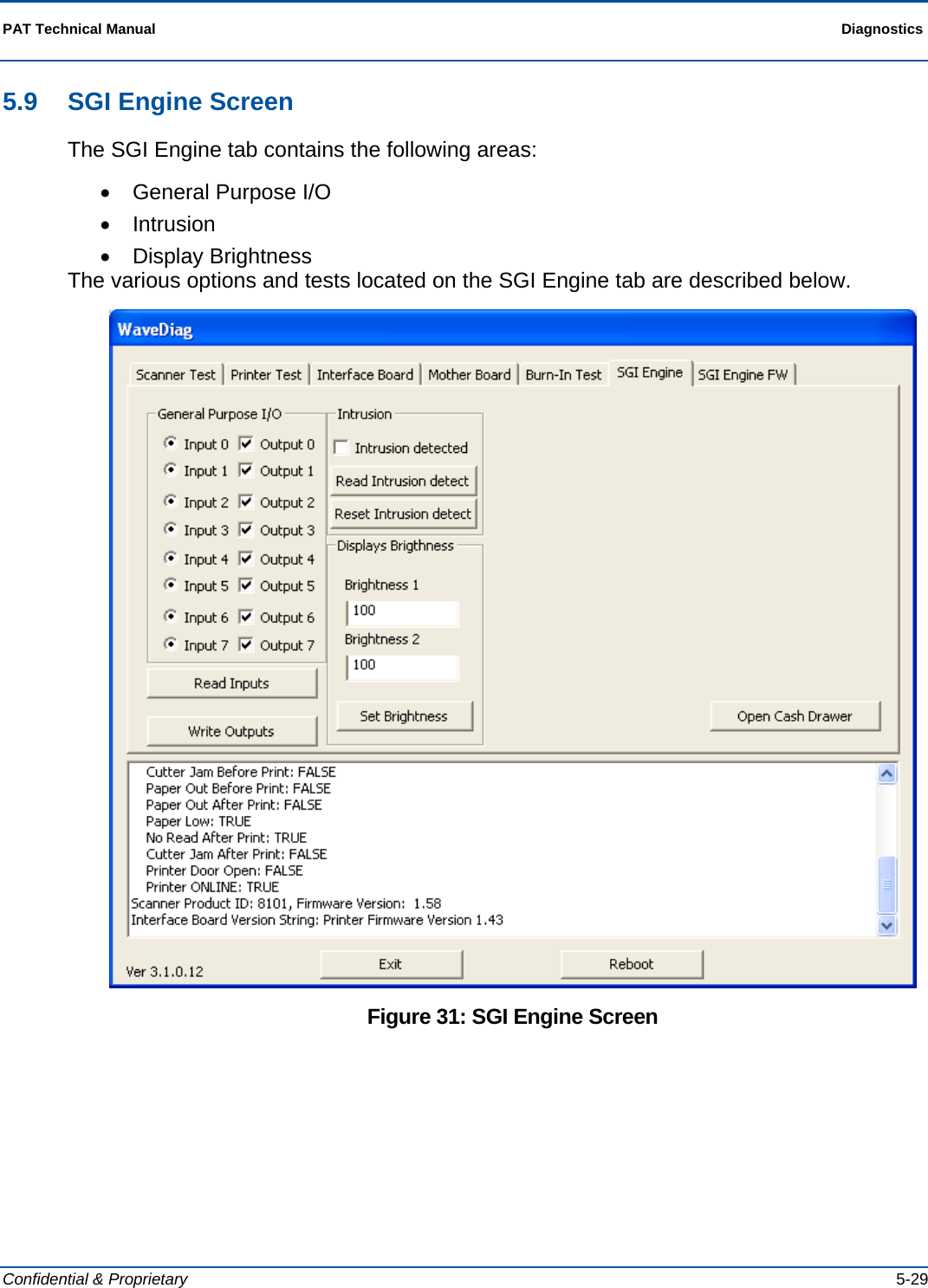
![Diagnostics PAT Technical Manual 5-30 Confidential & Proprietary 5.9.1 General Purpose I/O 5.9.1.1 Read Inputs Inputs column is updated with the current status on input 0-7. 5.9.1.2 Write Outputs Checked outputs will be set and unchecked cleared. 5.9.2 Intrusion 5.9.2.1 Reset Intrusion Detect Current status is be shown in the intrusion detect field. If there has been an intrusion it is checked, otherwise it is unchecked. 5.9.3 Displays Brightness Write the decried level from 100 – 255 in the box for brightness 1 and brightness 2 you want to change and press [Set Brightness]. NOTE: The WaveDiags will not set values outside the rage from 100 to 255.](https://usermanual.wiki/Scientific-Games/ITVM01/User-Guide-1644109-Page-94.png)
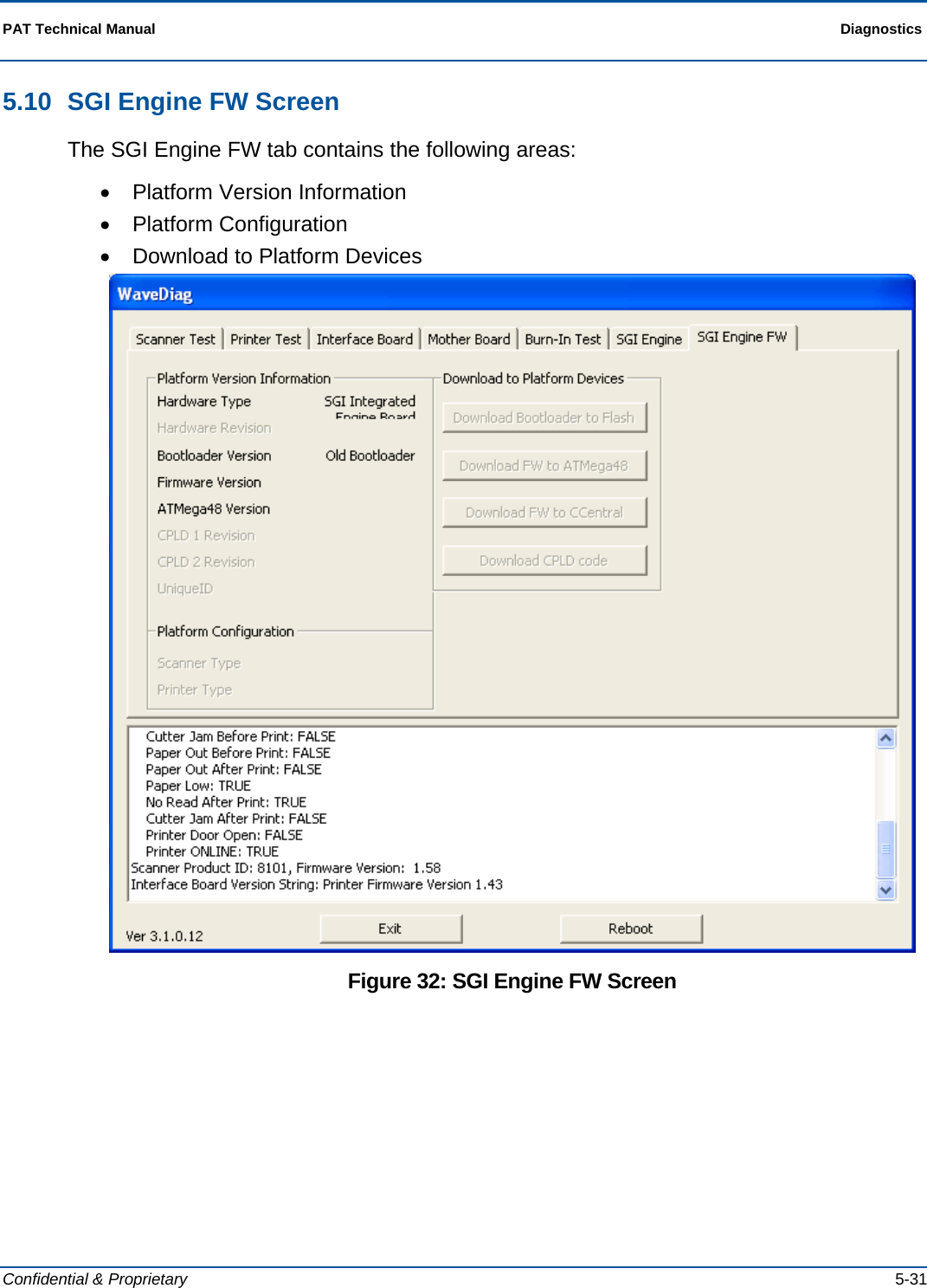
![PAT Technical Manual Diagnostics Confidential & Proprietary 5-33 5.10.3 Download to Platform Devices This area contains the following buttons: Download Bootloader to Flash Download FW to ATMega48 Download FW to Central Download CPLD code 5.10.3.1 Download Bootloader to Flash Description This function is used if the Bootloader Version is less than 2.02.05.00. Preconditions Unit must be operational. Starting the Test Select the [Download Bootloader to Flash] button. Flow Once the option is selected a windows navigation dialogue appears. Navigate to c:\bootloader and select the relevant file. When download finishes a message will appear in the Extrema Diag window. Ending the Test The test ends automatically when the bootloader has been downloaded. Analyzing Test Results Reboot PC to activate new Bootloader. The version will be displayed in the SGI Engine FW tab of Extrema Diag. Exceptions If the Bootloader Version is equal to or greater than 2.02.05.00 this option must be selected. Corrective Actions DNA](https://usermanual.wiki/Scientific-Games/ITVM01/User-Guide-1644109-Page-97.png)
![PAT Technical Manual Diagnostics Confidential & Proprietary 5-37 5.12 Bill Accepter Screen The Bill Accepter diagnostic functions are located in a separate program from the rest of the terminal’s diagnostics. To access the Bill Accepter diagnostics, click the GPT V2e icon. The technician will only use this screen to check or connect the communications for the terminal. To connect the communications, perform the following: 1. Double click the GPT V2e icon on the Windows desktop. The GPT V2e Host Controller App screen displays. 2. Press [V2]. 3. Ensure that COM3 is selected in the communication drop down. 4. Press [CONNECT]. Figure 34: Bill Accepter Screen](https://usermanual.wiki/Scientific-Games/ITVM01/User-Guide-1644109-Page-101.png)
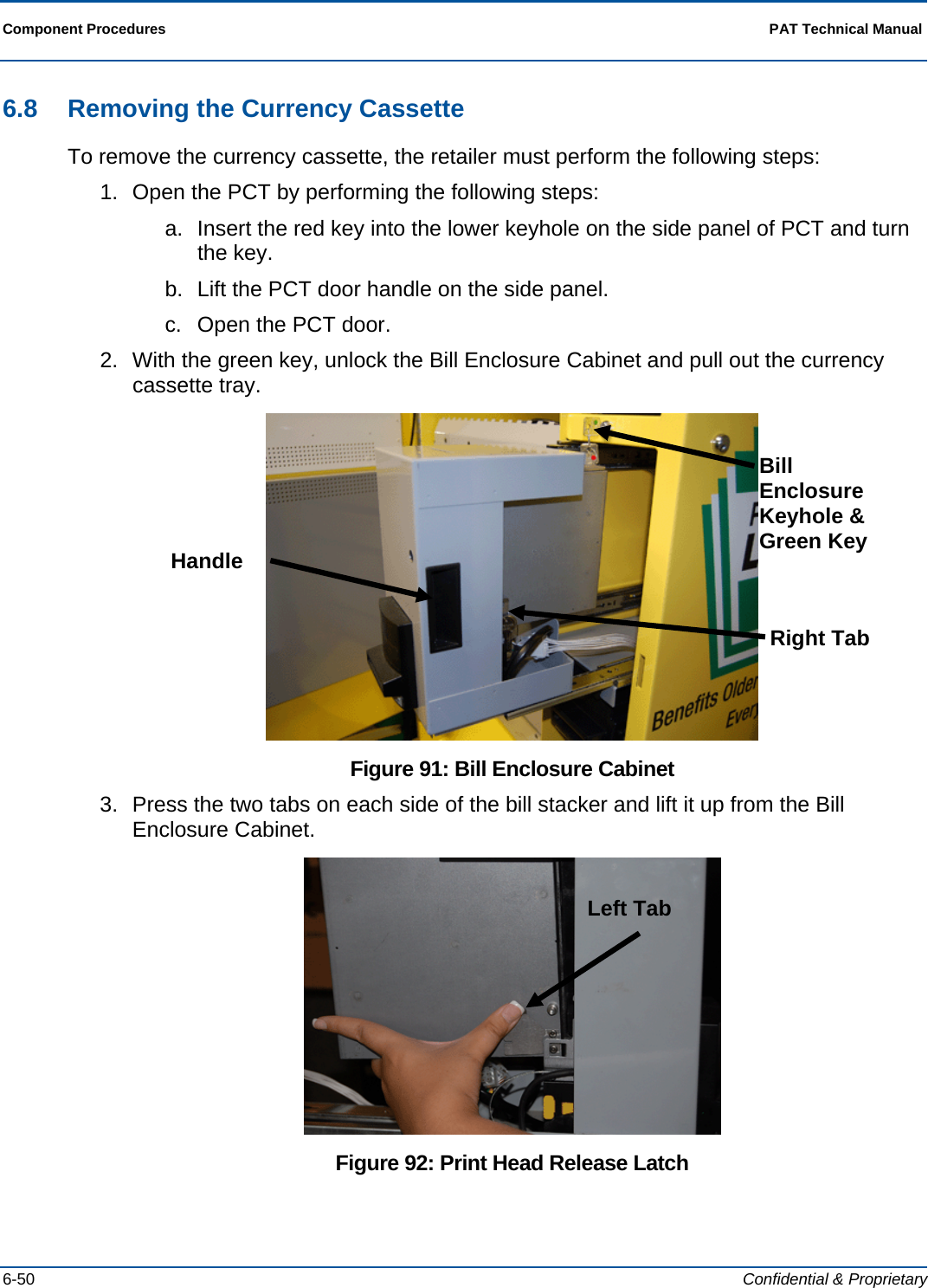
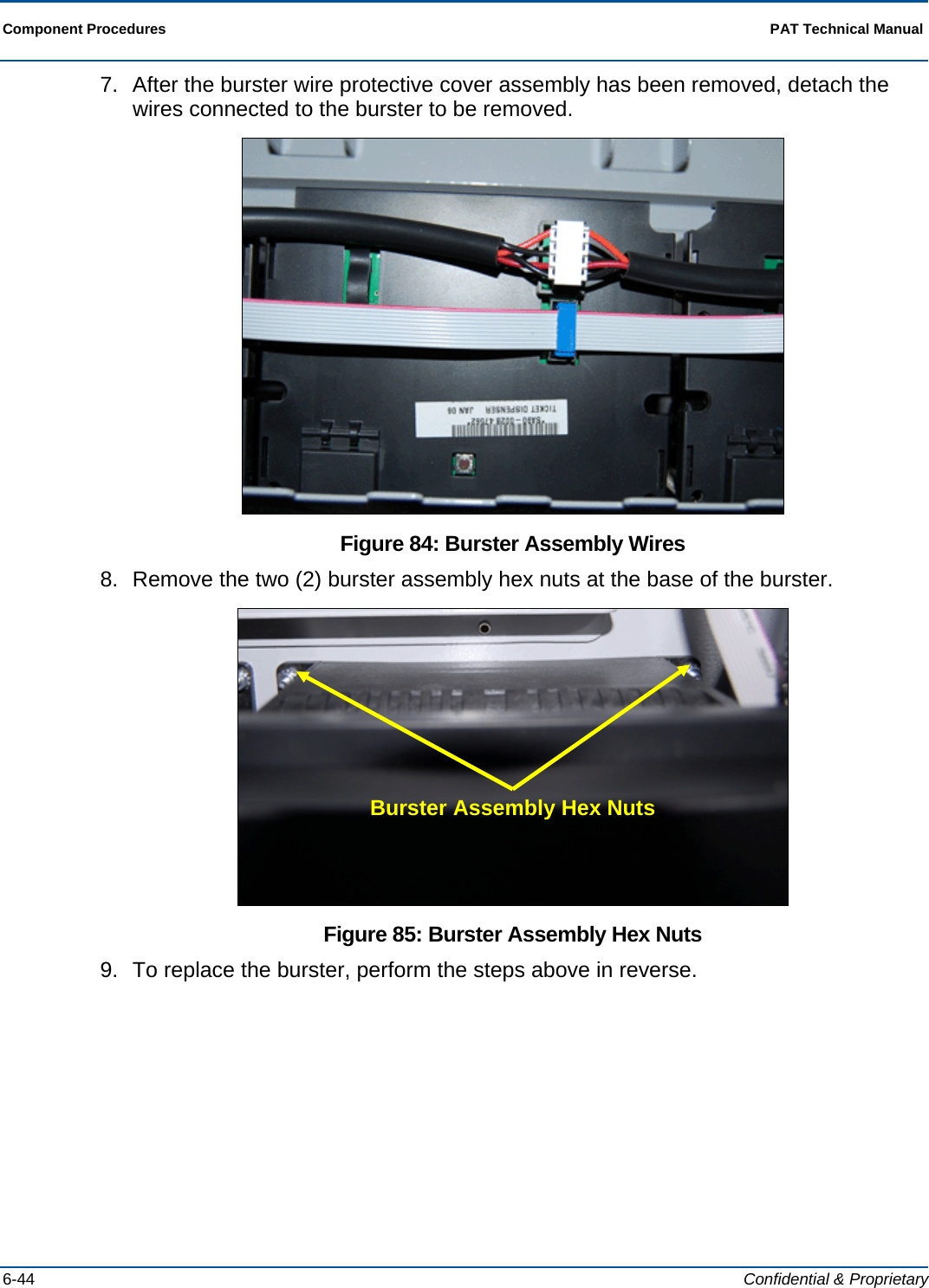
![Component Procedures PAT Technical Manual 6-42 Confidential & Proprietary 6.6 Instant Ticket Assembly The sections below provide the following procedures for these PCT components: • Loading Instant Tickets • Clearing an Instant Ticket Jam • Replacing the Burster 6.6.1 Loading Instant Tickets Up to three ticket packs may be loaded into a Burster at one time. To load a ticket pack, the retailer must perform the following steps: NOTE: Before loading instant ticket packs, make sure the packs have been activated. 1. Open the PAT: a. Insert the red key into the lower keyhole on the side panel and turn the key. b. Lift the PCT door handle on the side panel. c. Open the PCT door. 2. Insert the blue key into the top barrel lock and turn the key. 3. Touch [Burster Status]. 4. Touch [Load Pack] for the empty dispenser. The Enter Pack Number pop-up screen displays. 5. Either scan the Pack Activity Card or manually enter the Game/Pack number. The Game/Pack number is displayed. NOTE: The instant ticket validation barcode can also be scanned. 6. Verify the Game/Pack number that is displayed matched the Pack Activity Card. If they match, touch [OK]. 7. Touch [YES] to load a full pack or [NO] to load a partial pack. If loading a full pack, go to step 10. 8. Enter the starting ticket and touch [OK]. 9. Enter the ending ticket and touch [OK]. 10. Open the drawer and insert the lowest ticket number into the slot in the front of the dispenser. 11. If the pack is loaded correctly, a “Successfully Loaded” pop-up message displays. 12. Touch [OK] and close the drawer.](https://usermanual.wiki/Scientific-Games/ITVM01/User-Guide-1644109-Page-144.png)
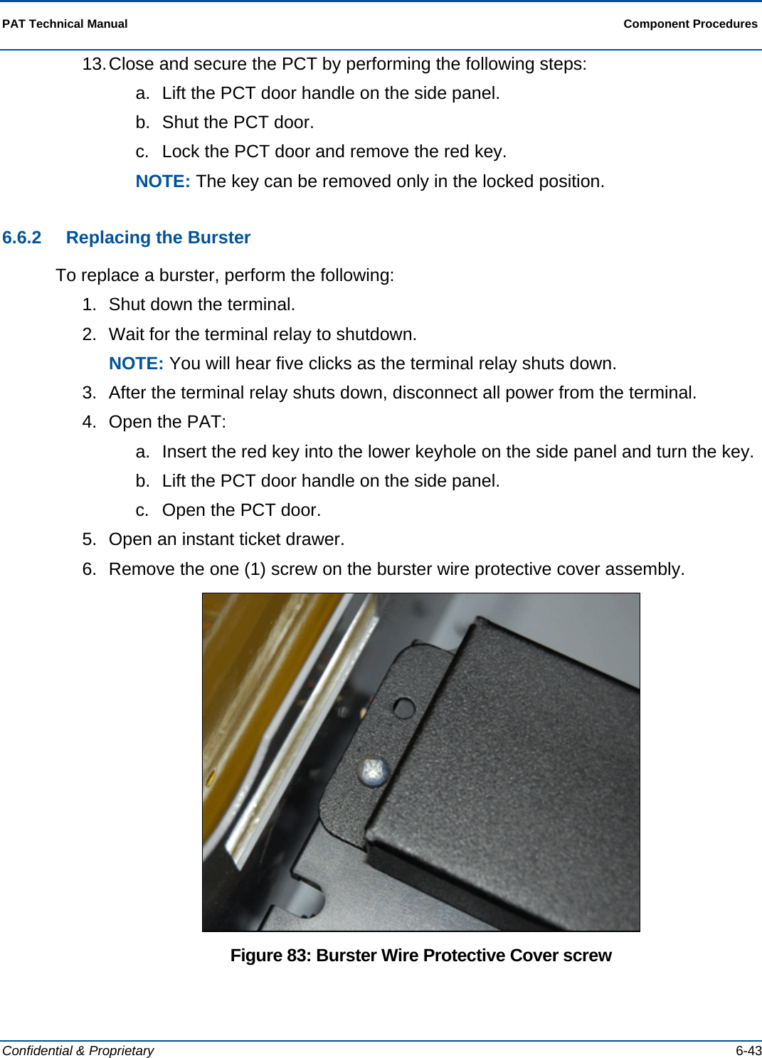
![PAT Technical Manual Component Procedures Confidential & Proprietary 6-45 6.6.3 Clearing an Instant Ticket Jam To clear a ticket jam in a Burster, perform the following: 1. Open the PAT: a. Insert the red key into the lower keyhole on the side panel and turn the key. b. Lift the PCT door handle on the side panel. c. Open the PCT door. 2. Insert the blue key into the top barrel lock and turn the key. 3. Touch [Burster Status]. 4. Pull out the Burster rack that has the jammed Burster. 5. Press the Reverse button located on the front top center of the Burster. The jammed ticket will reverse out of the Burster. Figure 86: Reverse Button on Burster 6. If the jammed ticket is damaged, remove it from the pack. 7. On the Ticket Burster screen, confirm that the Burster indicates an Empty status. 8. Reload the pack into the Burster. 9. Close and secure the PCT by performing the following steps: a. Lift the PCT door handle on the side panel. b. Shut the PCT door. c. Lock the PCT door and remove the red key. NOTE: The key can be removed only in the locked position. NOTE: The PCT does not reconcile inventory of damaged or otherwise unsellable tickets that are removed from a pack. Reverse button](https://usermanual.wiki/Scientific-Games/ITVM01/User-Guide-1644109-Page-147.png)