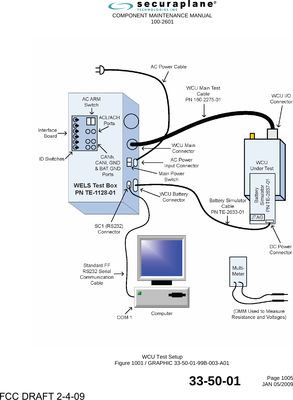
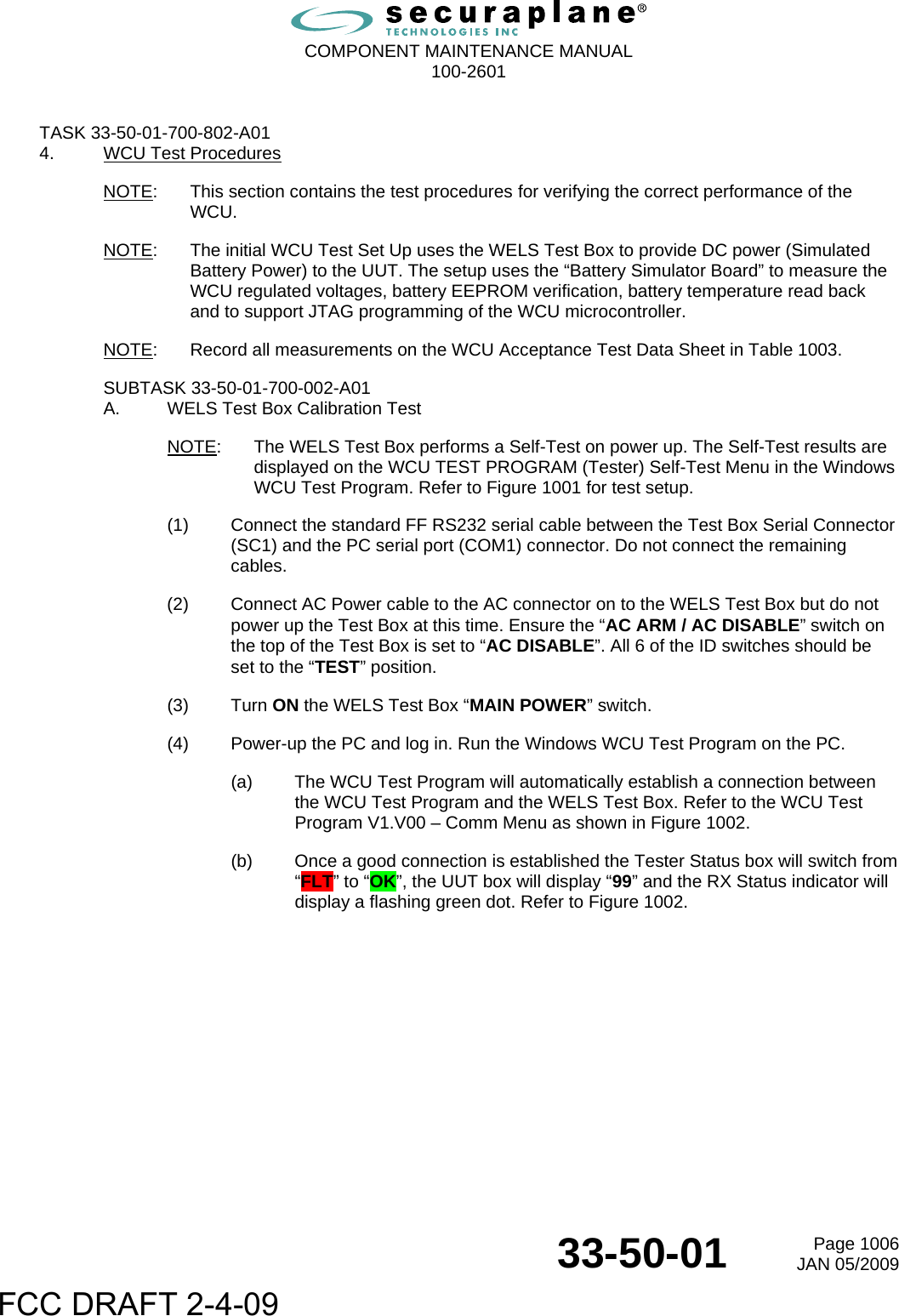
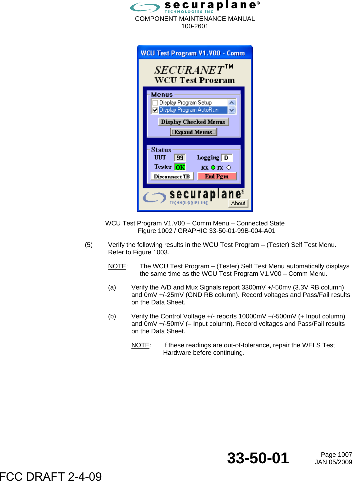
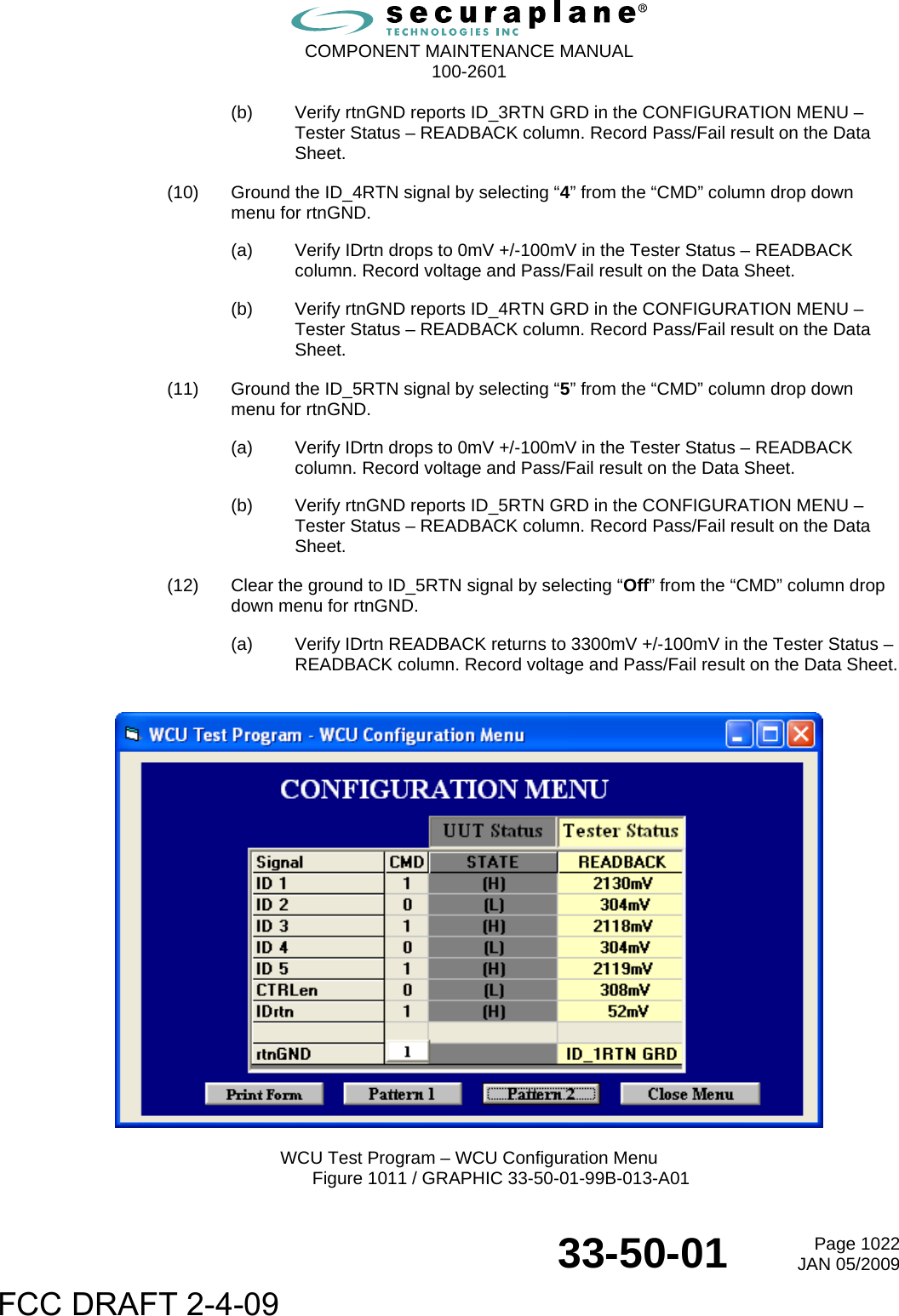
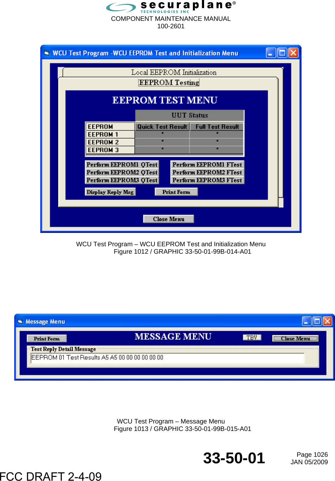
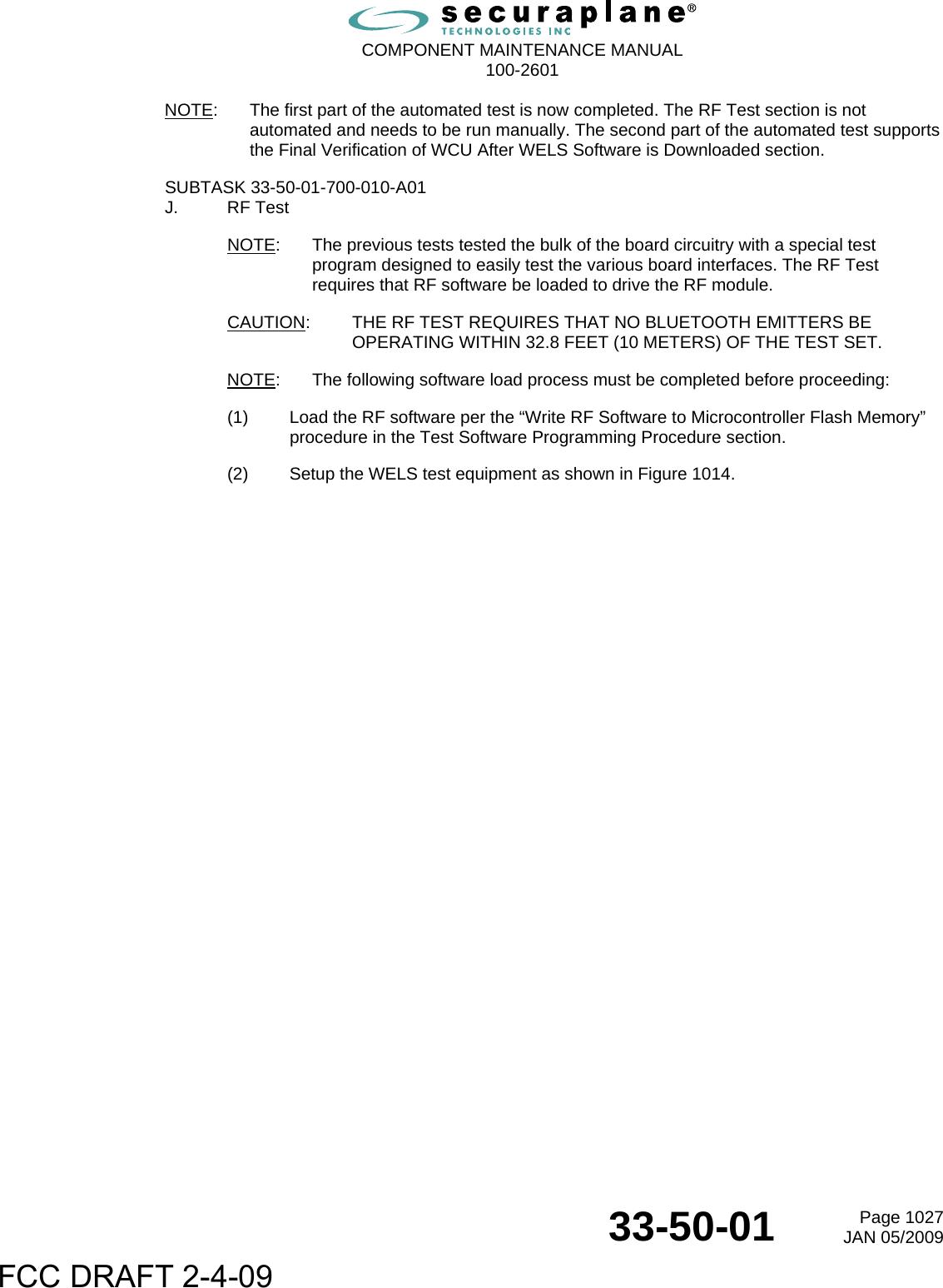
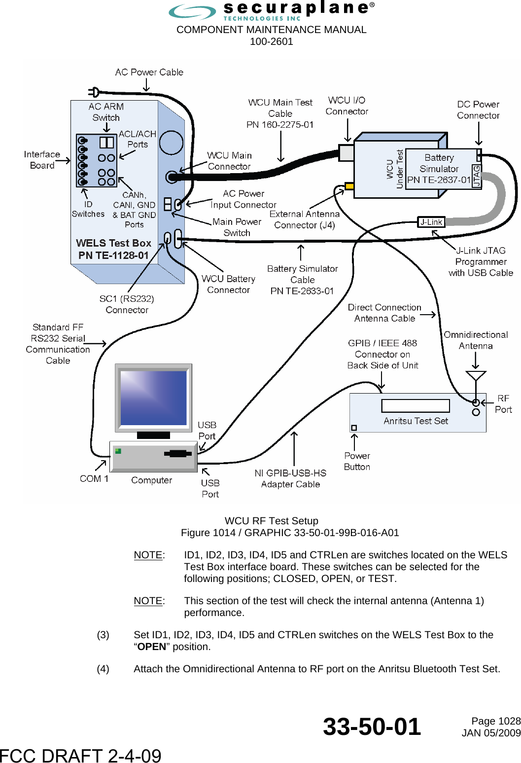
Securaplane Technologies WCU1002601 WELS Control Unit User Manual MM 0210 01 33 50 01 CMM WCU

Securaplane Technologies, Inc. WELS Control Unit MM 0210 01 33 50 01 CMM WCU

Users Manual

 CAGE Code: 0TMJ9 10800 Mavinee Drive  Tucson  AZ  85737 USA Tel: 1-520-297-0844  Fax 1-520-498-4924    Initial Issue: JAN 05/2009  Manual Part Number: MM-0210-01  33-50-01  Page TP1Revision No. – JAN 05/2009      COMPONENT MAINTENANCE MANUAL  WITH  ILLUSTRATED PARTS LIST       WELS CONTROL UNIT    PART NO. 100-2601-01            The technical data in this document (or file) is controlled for export under the Export Administration Regulations (EAR), 15 CFR Parts 730-774, ECCN: EAR99. Violations of these laws may be subject to fines and penalties under the Export Administration Act. FCC DRAFT 2-4-09
 COMPONENT MAINTENANCE MANUAL  100-2601   33-50-01  Page TP2JAN 05/2009              THIS PAGE INTENTIONALLY LEFT BLANK  FCC DRAFT 2-4-09
 COMPONENT MAINTENANCE MANUAL  100-2601  33-50-01  Page SWLA-1JAN 05/2009 SAFETY ADVISORY WARNING:  BEFORE THE MATERIALS CALLED OUT IN THIS PUBLICATION ARE USED, KNOW THE HANDLING, STORAGE AND DISPOSAL PRECAUTIONS RECOMMENDED BY THE MANUFACTURER OR SUPPLIER. FAILURE TO COMPLY WITH THE MANUFACTURERS' OR SUPPLIERS' RECOMMENDATIONS CAN RESULT IN PERSONAL INJURY OR DISEASE.   WARRANTY/LIABILITY ADVISORY SECURAPLANE ASSUMES NO RESPONSIBILITY FOR ANY SECURAPLANE EQUIPMENT WHICH IS NOT MAINTAINED AND/OR REPAIRED IN ACCORDANCE WITH SECURAPLANE’S PUBLISHED INSTRUCTIONS AND/OR SECURAPLANE’S REPAIR AUTHORIZATION. NEITHER DOES SECURAPLANE ASSUME RESPONSIBILITY FOR SPECIAL TOOLS AND TEST EQUIPMENT FABRICATED BY COMPANIES OTHER THAN SECURAPLANE. INCORRECTLY REPAIRED COMPONENTS CAN AFFECT AIRWORTHINESS OR DECREASE THE LIFE OF THE COMPONENTS. INCORRECTLY FABRICATED SPECIAL TOOLING OR TEST EQUIPMENT CAN RESULT IN DAMAGE TO PRODUCT COMPONENTS OR GIVE UNSATISFACTORY RESULTS.   CONFIDENTIALITY NOTICE  This document contains confidential and proprietary information, which is proprietary to Securaplane® and shall not be copied or reproduced, in whole or in part, or the contents divulged or used for manufacture, without the specific written permission of Securaplane. Recipient, by acceptance, use, or retention of this document, acknowledges and agrees to the foregoing and covenants to maintain the contents in confidence.   AIRCRAFT-ON-GROUND (AOG) SERVICE  For AOG service contact Securaplane at Tel: 1-520-297-0844 (US Toll Free: 1-800-279-7327). After business hours, follow the AOG directions in the recorded message.    FCC DRAFT 2-4-09
 COMPONENT MAINTENANCE MANUAL  100-2601  33-50-01 Page SWLA-2JAN 05/2009              THIS PAGE INTENTIONALLY LEFT BLANK  FCC DRAFT 2-4-09
 COMPONENT MAINTENANCE MANUAL  100-2601  33-50-01  Page SOC-1JAN 05/2009 STATEMENTS OF COMPLIANCE Regulatory Information for WELS Control Unit (WCU) Radio Transceiver A.  Statements and Conditions of Compliance (1)  This section contains information relative to domestic and foreign country Regulatory Approvals for the WELS radio. USA – FCC Compliance This device complies with part 15 of the Federal Communications Commission (FCC) Rules. Operation is subject to the following two conditions: (1)  This device may not cause harmful interference (2)  This device must accept any interference received, including interference that may cause undesired operation. FCC Section 15.21 statement – “Changes or modifications not expressly approved by the manufacturer could void the user’s authority to operate the equipment”.  Canada - Industry Canada Statements This Class B digital apparatus complies with Canadian ICES-003. Cet appareil numérique de la class B est conforme à la norme NMB-003 du Canada.  Europe – ETSI  Japan –   Argentina –   Israel –   Brazil –   China CCC –   Malta –   Jordan –   India –   Malaysia –   Morocco –   Nigeria –   FCC DRAFT 2-4-09
 COMPONENT MAINTENANCE MANUAL  100-2601  33-50-01  Page SOC-2JAN 05/2009              THIS PAGE INTENTIONALLY LEFT BLANK  FCC DRAFT 2-4-09
 COMPONENT MAINTENANCE MANUAL  100-2601  33-50-01  Page ROR-1JAN 05/2009 RECORD OF REVISIONS Revision Number  Issue Date  Date Inserted  By  Revision Number  Revision Date  Date Filed  By                                                                                                                                                                                                                                                                                                                                                                 FCC DRAFT 2-4-09
 COMPONENT MAINTENANCE MANUAL  100-2601  33-50-01  Page ROR-2JAN 05/2009              THIS PAGE INTENTIONALLY LEFT BLANK  FCC DRAFT 2-4-09
 COMPONENT MAINTENANCE MANUAL  100-2601  33-50-01  Page RTR-1JAN 05/2009 RECORD OF TEMPORARY REVISIONS Temporary Revision Number Page Number  Issue Date  By  Date Removed  By                                                                                                                                                                                                                          FCC DRAFT 2-4-09
 COMPONENT MAINTENANCE MANUAL  100-2601  33-50-01  Page RTR-2JAN 05/2009              THIS PAGE INTENTIONALLY LEFT BLANK  FCC DRAFT 2-4-09
 COMPONENT MAINTENANCE MANUAL  100-2601  33-50-01  Page SBL-1JAN 05/2009 SERVICE BULLETIN LIST Service Bulletin / Revision Number  Issue Date  Date Incorporated or No Effect Title                                                                                                                          FCC DRAFT 2-4-09
 COMPONENT MAINTENANCE MANUAL  100-2601  33-50-01  Page SBL-2JAN 05/2009              THIS PAGE INTENTIONALLY LEFT BLANK  FCC DRAFT 2-4-09
 COMPONENT MAINTENANCE MANUAL  100-2601  LIST OF EFFECTIVE PAGES 33-50-01  Page LEP-1JAN 05/2009 SUBJECT  PAGE DATE Title Page    TP1  JAN 05/2009   TP2 BLANK     Safety/ Warranty/    SWLA-1  JAN 05/2009 Liability Advisory    SWLA-2  BLANK     Statements of    SOC-1  JAN 05/2009 Compliance  SOC-2 BLANK     Record of     ROR-1  JAN 05/2009 Revision  ROR-2 BLANK     Temporary  RTR-1 JAN 05/2009 Revisions  RTR-2 BLANK     Service Bulletin     SBL-1  JAN 05/2009 List  SBL-2 BLANK     List of Effective     LEP-1  JAN 05/2009 Pages  LEP-2 JAN 05/2009     Table of     TOC-1  JAN 05/2009 Contents  TOC-2 JAN 05/2009     Introduction  INTRO-1 JAN 05/2009   INTRO-2 JAN 05/2009   INTRO-3 JAN 05/2009   INTRO-4 BLANK     Description and    1  JAN 05/2009 Operation  2 JAN 05/2009   3 JAN 05/2009   4 JAN 05/2009   5 JAN 05/2009   6 JAN 05/2009   7 JAN 05/2009   8 JAN 05/2009   9 JAN 05/2009   10 JAN 05/2009   11 JAN 05/2009   12 JAN 05/2009     Testing and Fault    1001  JAN 05/2009 Isolation  1002 JAN 05/2009   1003 JAN 05/2009   1004 JAN 05/2009   1005 JAN 05/2009   1006 JAN 05/2009   1007 JAN 05/2009   1008 JAN 05/2009 SUBJECT  PAGE DATE   1009 JAN 05/2009   1010 JAN 05/2009   1011 JAN 05/2009   1012 JAN 05/2009   1013 JAN 05/2009   1014 JAN 05/2009   1015 JAN 05/2009   1016 JAN 05/2009   1017 JAN 05/2009   1018 JAN 05/2009   1019 JAN 05/2009   1020 JAN 05/2009   1021 JAN 05/2009   1022 JAN 05/2009   1023 JAN 05/2009   1024 JAN 05/2009   1025 JAN 05/2009   1026 JAN 05/2009   1027 JAN 05/2009   1028 JAN 05/2009   1029 JAN 05/2009   1030 JAN 05/2009   1031 JAN 05/2009   1032 JAN 05/2009   1033 JAN 05/2009   1034 JAN 05/2009   1035 JAN 05/2009   1036 JAN 05/2009   1037 JAN 05/2009   1038 JAN 05/2009   1039 JAN 05/2009   1040 JAN 05/2009   1041 JAN 05/2009   1042 JAN 05/2009   1043 JAN 05/2009   1044 JAN 05/2009   1045 JAN 05/2009   1046 JAN 05/2009   1047 JAN 05/2009   1048 JAN 05/2009   1049 JAN 05/2009   1050 JAN 05/2009   1051 JAN 05/2009   1052 JAN 05/2009   1053 JAN 05/2009   1054 JAN 05/2009   1055 JAN 05/2009   1056 JAN 05/2009   1057 JAN 05/2009   1058 JAN 05/2009 FCC DRAFT 2-4-09
 COMPONENT MAINTENANCE MANUAL  100-2601  LIST OF EFFECTIVE PAGES 33-50-01  Page LEP-2JAN 05/2009 SUBJECT  PAGE DATE     Schematics and    2001  JAN 05/2009 Wiring Diagrams    2002  BLANK   2003 JAN 05/2009   2004 BLANK     Disassembly  3001 JAN 05/2009   3002 JAN 05/2009   3003 JAN 05/2009   3004 JAN 05/2009     Cleaning  4001 JAN 05/2009   4002 JAN 05/2009     Inspection/Check  5001  JAN 05/2009   5002 BLANK     Assembly  7001 JAN 05/2009   7002 JAN 05/2009   7003 JAN 05/2009   7004 JAN 05/2009     Fits and    8001  JAN 05/2009 Clearances  8002 JAN 05/2009     Special Tools,    9001  JAN 05/2009 Fixtures,  9002 JAN 05/2009 Equipment and       Consumables         Illustrated Parts    10001  JAN 05/2009 List (IPL)    10002  JAN 05/2009   10003 JAN 05/2009   10004 JAN 05/2009   10005 JAN 05/2009   10006 JAN 05/2009   10007 JAN 05/2009   10008 JAN 05/2009   10009 JAN 05/2009   10010 BLANK     Storage    (Including  15001 JAN 05/2009 Transportation)  15002 JAN 05/2009                         SUBJECT  PAGE DATE                                                                                  FCC DRAFT 2-4-09
 COMPONENT MAINTENANCE MANUAL  100-2601  33-50-01  Page TOC-1JAN 05/2009 TABLE OF CONTENTS SECTION          PAGE DESCRIPTION AND OPERATION       1 TESTING AND FAULT ISOLATION       1001 SCHEMATICS AND WIRING DIAGRAMS      2001 DISASSEMBLY          3001 CLEANING          4001 CHECK           5001 REPAIR          Not Applicable ASSEMBLY          7001 FITS AND CLEARANCES        8001 SPECIAL TOOLS, FIXTURES, EQUIPMENT AND CONSUMABLES      9001 ILLUSTRATED PARTS LIST        10001 SPECIAL PROCEDURES        Not Applicable REMOVAL          Not Applicable INSTALLATION          Not Applicable SERVICING          Not Applicable STORAGE          15001 REWORK          Not Applicable  FCC DRAFT 2-4-09
 COMPONENT MAINTENANCE MANUAL  100-2601  33-50-01  Page TOC-2JAN 05/2009 LIST OF FIGURES FIGURE           PAGE Figure 1. WELS Control Unit (WCU) ..........................................................................................................3 Figure 2. J1 Connector Insert Arrangement .............................................................................................10 Figure 1001. WCU Test Setup  .............................................................................................................1005 Figure 1002. WCU Test Program V1.V00 – Comm Menu – Connected State  ....................................1007 Figure 1003. WCU Test Program – (Tester) Self Test Menu ...............................................................1008 Figure 1004. WCU Test Program V1.V00 – Comm Menu – Disconnected State ................................1009 Figure 1005. WCU Test Program – WCU AutoRun Menu ...................................................................1011 Figure 1006. WCU Test Program – WCU Main Status Menu ..............................................................1013 Figure 1007. WCU Test Program – Message Menu – Over Voltage ...................................................1014 Figure 1008. WCU Test Program – WCU Outputs Status Menu .........................................................1015 Figure 1009. WCU Test Program – WCU Configuration Menu ............................................................1020 Figure 1010. WCU Test Program – WCU Configuration Menu ............................................................1021 Figure 1011. WCU Test Program – WCU Configuration Menu ............................................................1022 Figure 1012. WCU Test Program – WCU EEPROM Test and Initialization Menu  ..............................1026 Figure 1013. WCU Test Program – Message Menu  ............................................................................1026 Figure 1014. WCU RF Test Setup ........................................................................................................1028 Figure 1015. WCU Final Verification Test Setup with WELS Test Box PC ..........................................1031 Figure 1016. Message Menu – CAN Message  ....................................................................................1032 Figure 1017. WCU Final Verification Test Setup with Interface and ARM Boards ..............................1033 Figure 1018. Equipment Setup for Programming WCU .......................................................................1053 Figure 1019. SAM-PROG v2.3 Menu ...................................................................................................1055 Figure 1020. SAM-PROG Download Status ........................................................................................1056 Figure 2001. WELS Control Unit Schematic ........................................................................................2003 Figure 3001. WELS Battery Unit Removal ...........................................................................................3002 Figure 7001. Front Case Adhesive Channel ........................................................................................7004 Figure 8001. WELS Control Unit Fits and Clearances .........................................................................8002 IPL-Figure 1. WELS Control Unit Assembly .......................................................................................10006 IPL-Figure 2. Electronic Assembly  .....................................................................................................10008  LIST OF TABLES TABLES           PAGE Table Intro 1. Applicable Documents.................................................................................................. Intro-1 Table 1. Measurement Parameters ............................................................................................................9 Table 2. WCU Connector J1 Pin Assignments .........................................................................................11 Table 3. Leading Particulars .....................................................................................................................12 Table 1001. Technical Support and Data Package(s) / Test Specifications ........................................1001 Table 1002. Special Tools, Fixtures, and Test Equipment ...................................................................1003 Table 1003. WCU Acceptance Test Data Sheet ..................................................................................1035 Table 3001. Consumable Materials ......................................................................................................3001 Table 4001. Consumable Materials ......................................................................................................4001 Table 7001. Consumable Materials ......................................................................................................7001 Table 9001. Consumable Materials ......................................................................................................9001 Table 9002. Special Tools, Fixtures, and Test Equipment ...................................................................9002 Table 10001. Vendor Code List ..........................................................................................................10004 Table 15001. Consumable Materials ..................................................................................................15001  FCC DRAFT 2-4-09
 COMPONENT MAINTENANCE MANUAL  100-2601  33-50-01  Page INTRO-1JAN 05/2009 INTRODUCTION TASK 33-50-01-99F-801-A01 1. General Information SUBTASK 33-50-01-99F-001-A01 A. Introduction (1)  This Component Maintenance Manual (CMM) has the maintenance instructions for the WELS Control Unit (WCU). Securaplane Technologies of Tucson, AZ, U.S.A. makes the WCU. (2)  This CMM has the off-aircraft procedures for the WELS Control Unit (WCU). This CMM is not for use by a mechanic working on a WCU installed on the aircraft. The WCU must be returned to Securaplane or a facility approved by Securaplane for repair. SUBTASK 33-50-01-99F-002-A01 B Equipment Identification (1)  The configuration of the equipment is shown by part number, dash number, series number, and MOD number marked on the identification label. NOTE:  Incorporated MOD status is indicated on the WCU identification label by blackened MOD circle(s). SUBTASK 33-50-01-99F-003-A01 C. Applicable Documents (1)  The reference documents related to the WCU are listed in Table Intro 1. Table Intro 1. Applicable Documents / TABLE 33-50-01-99A-001-A01 Documents Document Number Abbreviated Component Maintenance Manual, WELS Antenna Unit (WAU), 33-50-02  Securaplane MM-0211-01 Abbreviated Component Maintenance Manual, WELS Battery Unit (WBU), 33-50-03  Securaplane MM-0212-01 Operator’s Manual, Securanet Field Strength Measurement System, 23-00-01  Securaplane OM-1013-01  FCC DRAFT 2-4-09
 COMPONENT MAINTENANCE MANUAL  100-2601  33-50-01  Page INTRO-2JAN 05/2009 SUBTASK 33-50-01-99F-004-A01 D.  Product Support Services (1)  Product support for the WCU is available from Securaplane at: Securaplane  CAGE Code: 0TMJ9 10831 Mavinee Drive  Tel:  1-520-297-0844 Tucson  AZ  85737 USA  Fax  1-520-498-4924 Email: support@securaplane.com  Web: www.securaplane.com SUBTASK 33-50-01-99F-005-A01 E. Verification Dates (1)  Dates of Shop Verification by actual performance: Testing and Fault Isolation    Verified TBD Disassembly    Verified TBD Assembly    Verified TBD Engineering Technical Review    Completed TBD SUBTASK 33-50-01-99F-006-A01 F. Revision Service (1)  This CMM is written in agreement with the Air Transport Association of America iSpec 2200 and AECMA Simplified English guidelines. (2)  A complete revision of this manual will be issued when necessary throughout the service life of the unit. (3)  A change bar in the margin will identify the revised text. If the entire page has changed, a change bar will appear in the lower right corner. SUBTASK 33-50-01-99F-007-A01 G.  Electrostatic Discharge  (1)  The items susceptible to electrostatic discharge are handled in agreement with  IPC-A-610. Refer to the IPC-A-610C specification Sections 3.2 and 3.3 for the definition of the standards and conditions. SUBTASK 33-50-01-99F-008-A01 H.  Maintenance Task Oriented Support System (MTOSS) (1)  The Maintenance Task Oriented Support System (MTOSS) system uses standard and unique number combinations to identify maintenance tasks and subtasks. The MTOSS numbering system includes the ATA chapter-section-subject number as well as a function code and unique identifiers. The purpose of the MTOSS numbering system is to provide a means for the automated sorting, retrieval and management of digitized data. FCC DRAFT 2-4-09
 COMPONENT MAINTENANCE MANUAL  100-2601  33-50-01  Page INTRO-3JAN 05/2009 SUBTASK 33-50-01-99F-009-A01 J. Abbreviations (1)  Abbreviations which may be used in this manual are defined below. Abbreviation Nomenclature A Ampere AC Alternating Current AOG  Aircraft on Ground ASSY Assembly ATA   Air Transport Association BITE Built-in-Test Equipment C  Celsius and/or Centigrade CAGE Commercial and Government Entity CM Centimeter(s) CMM Component Maintenance Manual CONT Continued DC Direct Current EIA Electronic Industry Association F Fahrenheit FAA Federal Aviation Administration FIG. Figure FT Feet Hz Hertz IEC International Electrotechnical Commission  IEEE  Institute of Electrical and Electronics Engineers INC Incorporated INTRO Introduction IPL  Illustrated Parts List IRE  Institute of Radio Engineers KG Kilogram(s) KPA Kilopascal(s) LB Pound(s) LED  Light Emitting Diode Abbreviation Nomenclature LRU  Line Replaceable Unit mA Milliamperes MAX Maximum MM Millimeter(s) MOD Modification NHA  Next Higher Assembly No. Number ORIG Original OZ Ounce PN Part Number PSIG  Pounds (each) square inch gage Qty Quantity REF Reference REV Revision SB Service Bulletin SI Standards International ST Street TBD  To Be Determined TR Temporary Revision TYP Typical USA  United States of America V Volt(s) VAC  Volts Alternating Current VDC  Volts Direct Current W Watt WAU  WELS Antenna Unit WBU  WELS Battery Unit WCU  WELS Control Unit WELS  Wireless Emergency Lighting System FCC DRAFT 2-4-09
 COMPONENT MAINTENANCE MANUAL  100-2601  33-50-01  Page INTRO-4JAN 05/2009              THIS PAGE INTENTIONALLY LEFT BLANK  FCC DRAFT 2-4-09
 COMPONENT MAINTENANCE MANUAL  100-2601  33-50-01  Page 1JAN 05/2009 DESCRIPTION AND OPERATION TASK 33-50-01-870-801-A01 1. Description SUBTASK 33-50-01-870-001-A01 A. Introduction (1)  This section has the physical description and operation for the WELS Control Unit (WCU). SUBTASK 33-50-01-870-002-A01 B.  WELS Control Unit (WCU) Radio Transceiver General Design Information (1)  The WCU radio transceiver utilizes the unlicensed 2.4 GHz Industrial Scientific Medical (ISM) band and operates in a frequency Hopping Spread Spectrum (FHSS) mode to combat frequency interference. (2)  The WCU system frequency band is 2400 to 2483.5 M Hz. The WELS operational frequency band is comprised of 79 FHSS RF channels spaced 1 MHz apart. (3)  To comply with out-of-band regulations in each country a guard band is used at the upper and lower band edge. •  The lower guard band is 2 MHz •  The upper guard band is 3.5 MHz (4)  The design for radio transmitter power is classified as follows: •  Minimum design output is 0.25 mW (-6 dBm) •  Nominal design output is 1 mW (0 dBm) •  Maximum design output 2.5 mW (4 dBm) (5)  The WCU uses an internal antenna for most installations. The WCU also has a provision for an external antenna if the WCU is installed in an area of the aircraft not conducive for operation with the internal antenna. (6)  The WCU uses one of two antennas depending on the location of the node within the aircraft. In the nominal case, each node will select its internal antenna. In areas where signal strength or node placement is an issue, nodes will use the external antenna. (7)  Antenna selection is accomplished via pin programming set by the wire harness at the node location. (8)  The internal antenna is a ¼ wave microstrip located adjacent to the programmable switch on the PWB (part of WCU p/n 100-2601-01). The other switch output feeds a SMA connector on the WCU and connects via coax to the approved external patch antenna (part number 100-2600-012) positioned to radiate to one or more other control units. Both antennas are designed and implemented by Securaplane Technologies. No other external antenna is approved for use on the assembly. FCC DRAFT 2-4-09
 COMPONENT MAINTENANCE MANUAL  100-2601  33-50-01  Page 2JAN 05/2009 (9)  The power limits specified are dictated by the class 2 Bluetooth radio transmitter implemented in the control unit as shown per the following:  Gain (dbi) Antenna 2402 MHz 2480 MHz Type Manufacturer Power Notes Internal - Microstrip  -2.45  -3.4  ¼ wave dipole  Securaplane Technologies  0.25mw (-6dBm) – 2.5mW (4dBm)  Integrated on WCU PCB External 2.73 1.11  Patch  Securaplane Technologies  0.25mw (-6dBm) – 2.5mW (4dBm)  Replaceable  SUBTASK 33-50-01-870-003-A01 C. WCU Description (1)  The WCU is part of the Wireless Emergency Lighting System (WELS). The WELS system will provide illumination and signage to enable passengers and crew to evacuate the aircraft in an emergency. (2)  The WELS system will employ 28 WCU’s to provide standalone short time power to the emergency lighting on a distributed basis. In addition another WCU may be installed to control the lights and signs inside the crew rest area. (3)  Each WCU is electrically identical. However each WCU is configurable to function as master prime unit, subordinate prime unit, crew rest remote unit, or other remote units. The configuration (location, class, or function) of a WCU is defined by pin strapping on its aircraft interface connector in conjunction with a loadable configuration data base. (4)  In a baseline configuration, one WCU will be assigned as the prime unit; three WCU’s will be assigned as subordinate prime units, while all other WCU’s will be assigned as remote units. (5)  All prime units will receive airplane status, control state data, configuration database downloads, BITE requests from the aircraft central computing resource via a wired CAN Bus. However only the master prime unit can send status to the aircraft central computer resource via the CAN Bus. No remote unit will be connected to the CAN Bus. All prime units communicate to the remote units via Bluetooth wireless links. In addition the prime units communicate to each other also via Bluetooth wireless links. In some situations where a remote unit or prime unit does not have reliable direct wireless access to a prime unit its wireless access will be indirect through a nearby remote unit. This network of interconnected Bluetooth piconets is referred to as a mesh network. (6)  The WCU consists of a battery charger powered from the aircraft 115VAC bus, a battery pack subsystem referred as the WELS Battery Unit (WBU), six lamp drivers that apply or disconnect battery voltage to separate strings of emergency lights, a Bluetooth wireless interface, a CAN Bus wired interface, a microprocessor based controller, a tri level control input which conveys the state of the emergency lighting system to the prime WCU’s, and pins that are jumpered by the aircraft wire bundle to convey the hierarchy and lighting load of the WCU. FCC DRAFT 2-4-09
 COMPONENT MAINTENANCE MANUAL  100-2601  33-50-01  Page 3JAN 05/2009 (7)  The WCU is a small plastic assembly that contains the wireless control unit’s electronics and replaceable battery pack. The assembly consists of the plastic case, the printed wire assembly, the battery pack, three Nylatch mounting fasteners, a battery latch, an I/O interface connector, and an antenna connector. The WCU is shown in Figure 1.                           WELS Control Unit (WCU) Figure 1 / GRAPHIC 33-50-01-99B-001-A01 FCC DRAFT 2-4-09
 COMPONENT MAINTENANCE MANUAL  100-2601  33-50-01  Page 4JAN 05/2009 TASK 33-50-01-870-802-A01 2. Operation SUBTASK 33-50-01-870-004-A01 A. WCU Operation (1)  The WCU requires a Wireless Battery Unit (WBU) in order to operate. The WBU is a replaceable battery pack that plugs into the WCU. (2)  115 VAC Input. (a)  The WCU receives a single phase, 360 to 800 Hz, 100 to 122VAC nominal (90 to 134VAC abnormal steady state) power from the aircraft to operate the battery charger portion of the WCU. All other portions of the WCU are powered from the output side of the battery charger. (b)  The WCU will not draw an input Volt Amp product in excess of 10.5 VA during charging of batteries. NOTE:  10.5VA corresponds to a 115VAC off line charger having a power factor of 0.8 and efficiency of 75% operating from an input line filter loading the line with 0.1uF capacitance and delivering 8.2V at 0.75 A to the battery. NOTE:  The AC input to the WCU is fused to prevent propagation of damage in the event of a component failure in the WCU. (c)  The WCU will employ an input common mode line filter of sufficient order and low cutoff frequency to prevent common mode voltages and currents generated by the battery charger from conducting emissions into the aircraft wire bundle at levels in violation of EMC requirement D6-16050-5 sections 8.1.2, 8.2.1. (d)  The WCU is capable of withstanding AC voltage transients 156% of nominal lasting 100ms without damage.  (For Reference Only: A 156% transient corresponds to a 254V peak difference across the AC input.) (e)  The WCU monitors for the presence or absence of 115VAC power. This status reports to the controller block as a switch closure (power present) or a switch open (power absent) on the digital input line AC_ON#. NOTE:  The controller block in turn will convert the switch open to a logic high via a resistive pull-up. The controller block will use this status in an algorithm to determine when to activate emergency lighting. The controller block will not declare the 115VAC as absent for interruptions of voltage lasting less than 0.25 second. (3) CAN Interface. (a)  The WCU supports communications with the aircraft 1Mbps CAN bus via a CAN 2.0 transceiver and 3 pins on the external connector: CANH, CANL, CAN_SHIELD. The WCU contains no bus terminations. The CAN_SHIELD is not grounded at the WCU. FCC DRAFT 2-4-09
 COMPONENT MAINTENANCE MANUAL  100-2601  33-50-01  Page 5JAN 05/2009 (4)  Pin Strapping Inputs. (a)  The controller block reads the presence or absence of jumpers in the aircraft wire bundle that tie 5 individual pairs of pins (ID1-ID5 respectively to ID1_RTN-ID5_RTN respectively) together on the WCU external connector. The controller block converts this reading into an ID that will point into a downloaded configuration database as to the class of lighting load the WCU is expected to support. (b)  The controller block will also detect the presence or absence of a jumper in the aircraft wire bundle across the CRTL_ENABLE and CTRL_ENABLE_RTN pins on the WCU external connector. If the jumper is present then the WCU is a prime unit and is connected to the CAN bus and the tri level control line. If the jumper is absent than the WCU is a remote unit. (5)  System Control Input. (a)  Each prime WCU unit measures the DC voltage on the CONTROL pin relative to the SIGNAL GROUND pin on the WCU external connector to determine the control state of the WELS. Based on this measurement the controller block of the prime WCU unit defines the WELS as in one of three control states: STATE   MEASURED VOLTAGE ON    0V to +6V OFF    >+6V to +15V ARMED >+15V (6)  Battery Loop In Out. (a)  To disconnect the battery charger and other active WCU circuitry from the battery pack subsystem (WBU) so that the battery pack maintains its charge whenever the WCU is disconnected from the aircraft wire bundle, the battery charger bus (VB) and the battery pack bus (B+) will be electrically isolated and routed to the BATTERY LOOP IN and BATTERY LOOP OUT pins respectively on the WCU external connector. When the WCU is plugged into the aircraft wire bundle a jumper in the bundle connects the pins together. This jumper is of sufficiently short length that it does not intrude into the lighting zone of the aircraft wire bundle. FCC DRAFT 2-4-09
 COMPONENT MAINTENANCE MANUAL  100-2601  33-50-01  Page 6JAN 05/2009 (7)  Lamp Driver Outputs. (a)  The WCU will route the battery charger bus (BATTERY LOOP IN pin on the WCU external connector) to six overcurrent protected switchable lamp drivers circuits. The six lamp drivers in turn will connect to six pins  (OUT1 – OUT6 respectively) on the WCU external connector. The OUT1 – OUT6 pins in turn pair up with the OUT1_RTN – OUT6_RTN pins respectively on the WCU external connector to mate via the aircraft wire bundle connector to up to six twisted wire pairs in the aircraft wire bundle. Each twisted wire pair provides power to a set of emergency light fixtures. The OUT1_RTN – OUT6_RTN pins will connect to the circuit ground plane which the lamp drivers reside on. (b)  Each lamp driver will be capable of sourcing 1.18 A continuously (6.9 watts at 5.85 to 8.2v) with a voltage drop between its input and output not exceeding 150mv at maximum ambient temperatures yet will trip on a overcurrent that exceeds 1.5A for more than 400 microseconds. During a trip the lamp driver will automatically open the connection between its input and output and report the trip as an active high digital output (OUT_1_OC – OUT_6_OC) to the controller block. The lamp driver will remain in trip until the controller block issues an active low reset command (OUT_RESET#) common to all lamp drivers. (c)  Each lamp driver will have an active low dedicated digital input (OUT_1_CMD# – OUT_2_CMD#) which the controller block can use to command the lamp driver to close the connection between its input and its output provided the lamp driver is out of trip. (d)  Each lamp driver will measure the current that it is sourcing and report the measurement as an analog voltage (OUT1_I – OUT6_I) to the controller block’s A/D converter. Each lamp driver will detect when its output voltage is above 2.5v and report the detection as an active low digital output (OUT_1_VBIT# – OUT_6_VBIT#) to the controller block. (8) Battery Charger. (a)  The battery charger is an off line flyback type current mode operated switching power converter with a magnetically isolated battery level regulated output controlled via an opto coupler isolated voltage and current sensing feedback loop. (b)  The off line converter incorporates full wave AC to DC line rectification, inrush current limiting and choke input bulk DC filtering to maintain a minimum AC power factor of 0.8 for all charger output loads up to and including 0.75A -10% and to limit inrush current during initial application of 115VAC power to 16A peak. FCC DRAFT 2-4-09
 COMPONENT MAINTENANCE MANUAL  100-2601  33-50-01  Page 7JAN 05/2009 (c)  The feedback loop of the converter regulates the output by observing two error signals, one the difference between the voltage sensed and a voltage set point and the other the difference between the current sensed and a current set point. The two error signals after separate loop filter compensation /amplification are diode OR’d to form the drive signal to the converter pulse width modulator. An increase in drive voltage reduces the duty factor of the modulator to reduce current delivered to the output. The current sensed will also be converted to a low pass filtered analog voltage CHG_I and sent to the controller block’s A/D converter for further monitoring. The voltage sensed will also be converted into an analog voltage VF_MON and sent to the controller block’s A/D converter for further monitoring. (d)  The current set point will be selectable by the micro controller via a digital control input LOW_I. The current set point will be 0.75A +/-10%, 0.15A  +/-10% respectively for a logic low, logic high respectively at this input. The voltage set point will be fixed at 8.2V +/-0.2V. (e)  The converter will be disabled or enabled by the micro controller via a digital control input: CHG_DISABLE. A logic high at this input prevents the converter switch transistor from turning on. A logic low allows normal operation. (f)  The converter output will connect to the battery charger bus (VB) through a series diode to prevent converter circuitry that is powered from the converter output from discharging the battery pack whenever the converter is disabled or not receiving AC power. The converter voltage sense will be at the battery charger bus (VB) side of the series diode. The voltage sense will not draw more than 150 microamps from the bus when the converter is not operating. (9)  Bluetooth Wireless Interface. (a)  The WCU will contain a complete, version 2.0 compliant, class 2 power level, basic rate Bluetooth radio subsystem to support wireless communications between WCU’s at ranges up to 10 meters maximum. (b)  The radio subsystem consists of the following components: •  Integrated Bluetooth baseband controller/ RF transceiver module with external crystal. •  RF dielectric BPF to reduce receiver desensitization from out of band interferences. •  Antenna switch to connect BPF and transceiver to internal antenna or to RF connector. •  Internal Printed Inverted F (PIFA) antenna located at the edge of the PCB card well away from the battery charger and on the opposite side of the card from the battery pack (WBU) to optimize the antenna radiation pattern. FCC DRAFT 2-4-09
 COMPONENT MAINTENANCE MANUAL  100-2601  33-50-01  Page 8JAN 05/2009 •  RF connector to allow connection to an external antenna in cases where the WCU is located next to RF absorbent materials and is unable to establish a reliable wireless link to any other WCU. •  Local low noise dual linear voltage regulator preceded by an input LC ripple filter. (c)  The WCU will utilize a National Semiconductor LMX5453 integrated Bluetooth 2.0 baseband controller/ RF transceiver module. The frequency reference for the module will be a 13.0 MHz crystal with an ESR of <100 ohms for low oscillator sideband noise and with an accuracy of better than 15 ppm from -15 to +55 deg C to insure that the cumulative frequency accuracy of the complete radio is always within 20 ppm. (d)  The module will interface to the controller block via its UART port (module pins TXD, RXD, RTS#, CTS#). NOTE:  The signal naming of these module pins is as if the module is Data Terminal Equipment and not Data Set Equipment. That is, RTS# and TX are outputs whereas CTS# and RX are inputs. To prevent confusion, the interface lines from the controller block to module pins TXD, RXD, RTS#, CTS# will be called BT_TXD, BT_RXD, BT_RTS#, BT_CTS# respectively. (e)  The internal antenna identified earlier in this section will have characteristics equal to or better than the following: • Center Frequency:   2442 MHz •  Input Impedance:      50 ohms nominal •  Return Loss vs Frequency:    10 dB min from 2400 to 2485 MHz  •  Peak Gain (typ) vs Frequency:  + 3dBi at 2442 MHz, 0 dBi at       2402 MHz or 2480MHz. (f)  The external RF connector is a SMA female bulkhead right angle PCB mount connector. (10) Controller Block (a)  The controller block consists of the following components: •  Atmel AT91SAM7X256 32-bit RISC microcontroller. •  18.432 MHz crystal to control the frequency of the microcontroller. •  256kbit serial EEPROM. •  4Mbit serial FLASH memory. •  JTAG connector to load the initial program. FCC DRAFT 2-4-09
 COMPONENT MAINTENANCE MANUAL  100-2601  33-50-01  Page 9JAN 05/2009 •  DEBUG PORT connector for initial debugging. •  POR chip to initialize the microcontroller at power up. •  8 channel analog mux to select and route one of the OUT_1 to OUT_6 signals to an A/D input of the microcontroller. •  CAN Bus 2.0 transceiver. •  Dual linear voltage regulator to convert the battery charger bus voltage (VB) to supply voltages (3.3V, 5V) required for all digital logic within the WCU except the Bluetooth wireless block. (b)  The Atmel microcontroller internal features include a CAN interface, 64kbytes of SRAM, 256kbytes of FLASH memory, an 8 channel 10-bit resolution ADC, etc. The integral non-linearity, offset error, and gain error of the ADC is +/- 3, +/- 2, +/-2 bits maximum respectively. Assuming the ADC reference is connected to the 3.3V (+/- 2.9 %) output of the dual linear regulator then the input scaling/ADC chain will measure the following parameters to within the uncertainties shown in Table 1. Table 1. Measurement Parameters / TABLE 33-50-01-99A-002-A01 Parameter Sensed  Value Input Scaling Measurement Uncertainty   Sys cntrl i/p voltage  12V  0.1350 V/V  +/- 4.0 %  (CONTROL – CONTROL_RETURN) Lamp driver current  1.0A  2.0 volts/amp  +/- 3.9 %  (via OUT_1 – OUT_6 signals) Charger output current  0.75A 3.16volts/amp +/- 3.6 %  (via CHG_I signal) Charger bus voltage  8.4V  0.3329 V/V  +/- 3.4 %  (VB) NOTE:  The uncertainties listed here were estimated from a statistical assumption that all contributions to the total uncertainty are statistically independent and that the variance of the total uncertainty is equal to the sum of the variances of the individual contributors.  (c)  The microcontroller will shutdown or enables the 5V output of the dual linear regulator by applying a logic low or logic high respectively to the 5V_ENABLE digital input of the regulator. NOTE:  The 3.3V output of this regulator is always enabled since this output provides the supply voltage to the microcontroller. FCC DRAFT 2-4-09
 COMPONENT MAINTENANCE MANUAL  100-2601  33-50-01  Page 10JAN 05/2009 SUBTASK 33-50-01-870-005-A01 B.  WCU External Electrical Interfaces (1)  The WCU has two electrical connectors. The I/O Interface Connector, designated J1, brings in airplane power and signals as well as sends out power to the emergency lights and signs. The Antenna Connector, designated J4, is used to connect to the Wireless Antenna Unit in locations where the remote antenna is needed. See  Figure 2 for the WCU J1 connector layout. NOTE:  If the WAU is not needed install the dust cap on the antenna connector.                    J1 Connector Insert Arrangement Figure 2 / GRAPHIC 33-50-01-99B-002-A01 FCC DRAFT 2-4-09
 COMPONENT MAINTENANCE MANUAL  100-2601  33-50-01  Page 11JAN 05/2009 (2)  The J1 pin out assignments is shown in Table 2. Table 2. WCU Connector J1 Pin Assignments / TABLE 33-50-01-99A-003-A01 J1 Pin  Signal 1 115 VAC 2  115 VAC Return 3 Reserved 4  Driver # 1 5  Driver # 1 Return 6  Driver # 2 7  Driver # 2 Return 8  Driver # 3 9  Driver # 3 Return 10  Driver # 4 11  Driver # 4 Return 12  Driver # 5 13  Driver # 5 Return 14  Driver # 6 15  Driver # 6 Return 16  ID # 1 17  ID # 1 Return 18 Reserved 19 Reserved 20 Reserved 21  ID # 2 22  ID # 2 Return 23  ID # 3 24  ID # 3 Return 25  ID # 4 26  ID # 4 Return 27  ID # 5 28  ID # 5 Return 29  Battery Loop Out 30  Battery Loop In 31 Control Enable 32  Control Enable Return 33 CANH 34 CANL 35 CAN Shield 36 Control Return 37 Control  FCC DRAFT 2-4-09
 COMPONENT MAINTENANCE MANUAL  100-2601  33-50-01  Page 12JAN 05/2009 TASK 33-50-01-870-803-A01 3. Leading Particulars SUBTASK 33-50-01-870-006-A01 A.  WCU Leading Particulars (1)  The leading particulars for the WCU are shown in Table 3. Table 3. Leading Particulars / TABLE 33-50-01-99A-004-A01 Parameter Specification Power:     Input voltage  115 VAC Physical:     Height  2.06 inches (52.32 mm) maximum (including the plunger and grommet)   Width  4.43 inches (112.52 mm) maximum   Length  6.02 inches (152.91 mm) maximum   Weight  0.51 ± 0.05 lbs (0.23 ± 0.023 kg) (Without WELS Battery Unit) Bluetooth:     Wireless interface  Version 2.0 compliant, class 2 power level   Range  10 meters maximum   Frequency band  ISM band of 2.4 to 2.485 GHz   Maximum transmit lever  +4dBm Operating Environment  MINIMUM  MAXIMUM   Ground Survival Temperature -67°F (-55°C)  185°F (85°C)   Short Term Operation  -40°F (-40°C)  158°F (70°C)   Continuous Operation  5°F (-15°C)  131°F (55°C)   Normal Ground Operation  –  113°F (45°C)   Normal Flight Operation  –  86°F (30°C)   Case Temperature  –  203°F (95°C) Connectors:     J1 Circular Connector  BACC63CU15-35PN (MIL Standard D38999/20MD35PN)    J1 Mating Connector  BACC63CT15-35SN (MIL Standard D38999/26MD35SN)    J4 Antenna Connector  SMA RF Connector, mates with WELS Antenna Unit  FCC DRAFT 2-4-09
 COMPONENT MAINTENANCE MANUAL  100-2601  33-50-01  Page 1001JAN 05/2009 TESTING AND FAULT ISOLATION TECHNICAL SUPPORT AND DATA PACKAGE  1. Introduction A.  This section describes the Return-To-Service test (RTS) for the Unit-Under-Test (UUT).  The RTS is derived from the Technical Support and Data Package (TSDP) shown in  Table 1001. 2.  Technical Support and Data Package (TSDP) A.  The TSDP and Test Specification can be ordered from the address shown in paragraph 3. The Test Specification is the basis for the specified TSDP and the shop verified procedure in this CMM. Technical Support and Data Package(s) / Test Specifications Table 1001 UUT PART NUMBER  TEST SPECIFICATION PART NUMBER/REVISION  TSDP PART NUMBER/REVISION 100-2601-01  210-2601-03 / Rev C  291-0001-01 / Rev –  3. Ordering Information A.  The TSDP can be ordered from: Securaplane  CAGE Code: 0TMJ9 10831 Mavinee Drive  Tel:  1-520-297-0844 Tucson  AZ  85737 USA  Fax  1-520-498-4924 Email: support@securaplane.com  Web: www.securaplane.com  FCC DRAFT 2-4-09
 COMPONENT MAINTENANCE MANUAL  100-2601  33-50-01  Page 1002JAN 05/2009 TESTING AND FAULT ISOLATION TASK 33-50-01-99F-802-A01 1. General Information SUBTASK 33-50-01-99F-010-A01 A. Introduction WARNING:  BEFORE MATERIALS CALLED OUT IN THIS PUBLICATION ARE USED, KNOW THE HANDLING, STORAGE, AND DISPOSAL PRECAUTIONS RECOMMENDED BY THE MANUFACTURER OR SUPPLIER. FAILURE TO FOLLOW THE MANUFACTURERS’ OR SUPPLIERS’ RECOMMENDATIONS CAN RESULT IN PERSONAL INJURY OR DISEASE. CAUTION:  THESE PROCEDURES MUST BE DONE AT A STATIC-FREE WORKSTATION IN ORDER TO PREVENT DAMAGE TO ELECTROSTATIC SENSITIVE COMPONENTS. CAUTION:  THIS UNIT HAS ASSEMBLIES THAT ARE SUSCEPTIBLE TO DAMAGE FROM INCORRECT HANDLING. DO NOT DROP OR HIT THE UNIT DURING THESE PROCEDURES. CAUTION:  THESE PROCEDURES MUST BE DONE IN A CLEAN ENVIRONMENT IN ORDER TO PREVENT DAMAGE TO MECHANICAL COMPONENTS. (1)  This section has the testing and fault isolation information for the WELS Control Unit (WCU). TASK 33-50-01-94B-801-A01 2.  Equipment and Materials SUBTASK 33-50-01-94A-001-A01 A. Consumable Materials (1)  No consumable materials are needed for Testing and Fault Isolation procedures. SUBTASK 33-50-01-94B-001-A01 B.  Special Tools, Fixtures, and Test Equipment (1)  Special tools and test equipment used during the Testing and Fault Isolation procedures are shown in Table 1002. NOTE:  Equivalent alternatives can be used. FCC DRAFT 2-4-09
 COMPONENT MAINTENANCE MANUAL  100-2601  33-50-01  Page 1003JAN 05/2009 Special Tools, Fixtures, and Test Equipment Table 1002 / TABLE 33-50-01-99A-005-A01 Equipment Characteristics Accuracy Source or (CAGE) WELS Test Box  TE-1128-01    V0TMJ9 WCU Main Test Cable   160-2275-01    V0TMJ9 Battery Simulator Module   TE-2637-01    V0TMJ9 Battery Simulator Cable   TE-2633-01    V0TMJ9 WELS Battery Unit (Fully Charged to 8.4 Volts)  100-2602-01  V0TMJ9 Standard FF RS232 Communication Serial Cable (DB9 to DB9) AK152-2-R  Commercially available Computer  Microsoft Windows XP Professional Operating System with (2) available USB Ports and (1) available Serial Port. 512 MB RAM (memory) 10 MB of hard disk space available. PC must also have access to a printer.  Commercially available WCU Test Program, V1.V00  050-0224-07341 Rev -    V0TMJ9 WCU Main Test Code (8MB Flash-U35)  050-0232-08031 Rev -    V0TMJ9 WCU RF Test Code  050-0230-07341 Rev -    V0TMJ9 WELS 787 Operational SW Code  050-0211-08237 Rev -    V0TMJ9 BlueTest2 Software  Version 1.0.0 Rev 1 (or later)    VU4252 Bluetooth Test Set  Anritsu MT8852A    VU4252 Adapter Cable (and windows driver)  National Instruments GPIB-USB-HS   V64667 Direct Connection Antenna Cable  Pasternack PN PE3876-60  (5 feet in length recommended)  V53919 Omnidirectional Antenna  Antenova PN 2010B4844-01    V53919 Digital Multimeter  True RMS Multimeter  0 to 10 VDC (Fluke 87)  1 %  V89536 J-Link (USB to JTAG Debugger/Programmer)  IAR Systems    V1QQS1 SAM-PROG v2.3 (or later)  Atmel Corp    V1FN41  FCC DRAFT 2-4-09
 COMPONENT MAINTENANCE MANUAL  100-2601  33-50-01  Page 1004JAN 05/2009 TASK 33-50-01-700-801-A01 3. Test Procedures SUBTASK 33-50-01-700-001-A01 A. Test Requirements (1)  Do all tests with the test unit at the following conditions, unless otherwise specified by an individual test procedure. Ambient room temperature  +68 to 86°F (+20 to 30°C) Humidity      Ambient up to 85% relative Input Voltage   115.0 ± 5 VAC (2)  Regularly examine and certify instrument accuracy/calibration in accordance with applicable government and commercial specifications. (3)  Visually inspect the unit for signs of missing, broken, bent or cracked parts. Damaged parts must be replaced before the unit is tested. (4)  Unless otherwise specified, all tolerances are ±1%. (5)  Disassemble the WCU to subassembly level per the DISASSEMBLY section. (6)  The test setup for the WCU is shown in Figure 1001. NOTE:  Before any tests are performed, ensure the WELS Battery Unit (WBU) is not still installed in the WCU. If the battery is installed continue to the DISASSEMBLY section for battery removal instructions. FCC DRAFT 2-4-09
 COMPONENT MAINTENANCE MANUAL  100-2601  33-50-01  Page 1005JAN 05/2009    WCU Test Setup Figure 1001 / GRAPHIC 33-50-01-99B-003-A01 FCC DRAFT 2-4-09
 COMPONENT MAINTENANCE MANUAL  100-2601  33-50-01  Page 1006JAN 05/2009  TASK 33-50-01-700-802-A01 4.  WCU Test Procedures NOTE:  This section contains the test procedures for verifying the correct performance of the WCU. NOTE:  The initial WCU Test Set Up uses the WELS Test Box to provide DC power (Simulated Battery Power) to the UUT. The setup uses the “Battery Simulator Board” to measure the WCU regulated voltages, battery EEPROM verification, battery temperature read back and to support JTAG programming of the WCU microcontroller. NOTE:  Record all measurements on the WCU Acceptance Test Data Sheet in Table 1003. SUBTASK 33-50-01-700-002-A01 A.  WELS Test Box Calibration Test NOTE:  The WELS Test Box performs a Self-Test on power up. The Self-Test results are displayed on the WCU TEST PROGRAM (Tester) Self-Test Menu in the Windows WCU Test Program. Refer to Figure 1001 for test setup. (1)  Connect the standard FF RS232 serial cable between the Test Box Serial Connector (SC1) and the PC serial port (COM1) connector. Do not connect the remaining cables. (2)  Connect AC Power cable to the AC connector on to the WELS Test Box but do not power up the Test Box at this time. Ensure the “AC ARM / AC DISABLE” switch on the top of the Test Box is set to “AC DISABLE”. All 6 of the ID switches should be set to the “TEST” position. (3) Turn ON the WELS Test Box “MAIN POWER” switch. (4)  Power-up the PC and log in. Run the Windows WCU Test Program on the PC. (a)  The WCU Test Program will automatically establish a connection between the WCU Test Program and the WELS Test Box. Refer to the WCU Test Program V1.V00 – Comm Menu as shown in Figure 1002. (b)  Once a good connection is established the Tester Status box will switch from “FLT” to “OK”, the UUT box will display “99” and the RX Status indicator will display a flashing green dot. Refer to Figure 1002. FCC DRAFT 2-4-09
 COMPONENT MAINTENANCE MANUAL  100-2601  33-50-01  Page 1007JAN 05/2009    WCU Test Program V1.V00 – Comm Menu – Connected State Figure 1002 / GRAPHIC 33-50-01-99B-004-A01 (5)  Verify the following results in the WCU Test Program – (Tester) Self Test Menu. Refer to Figure 1003. NOTE:  The WCU Test Program – (Tester) Self Test Menu automatically displays the same time as the WCU Test Program V1.V00 – Comm Menu. (a)  Verify the A/D and Mux Signals report 3300mV +/-50mv (3.3V RB column) and 0mV +/-25mV (GND RB column). Record voltages and Pass/Fail results on the Data Sheet. (b)  Verify the Control Voltage +/- reports 10000mV +/-500mV (+ Input column) and 0mV +/-50mV (– Input column). Record voltages and Pass/Fail results on the Data Sheet. NOTE:  If these readings are out-of-tolerance, repair the WELS Test Hardware before continuing. FCC DRAFT 2-4-09
 COMPONENT MAINTENANCE MANUAL  100-2601  33-50-01  Page 1008JAN 05/2009      WCU Test Program – (Tester) Self Test Menu Figure 1003 / GRAPHIC 33-50-01-99B-005-A01 (6)  Disconnect the communication link between the WCU Test Program and the WELS Test Box by clicking on the “Disconnect TB” button in the WCU Test Program V1.V00 - Comm Menu. Refer to Figure 1002. (a)  Once the connection has ended the Tester Status box will switch from “OK” to “FLT”, the UUT box will display “?” and the RX Status indicator will be blank. Refer to Figure 1004. FCC DRAFT 2-4-09
 COMPONENT MAINTENANCE MANUAL  100-2601  33-50-01  Page 1009JAN 05/2009    WCU Test Program V1.V00 – Comm Menu – Disconnected State Figure 1004 / GRAPHIC 33-50-01-99B-006-A01 (7) Turn OFF the Test Box “MAIN POWER” switch. Leave AC Power Cable connected to Test Box. SUBTASK 33-50-01-700-003-A01 B.  Initial WCU Power-Up NOTE:  Refer to Figure 1001 for the test setup. (1)  Carefully install the Battery Simulator Module in the WCU battery slot making sure not to bend any connector pins. (2)  Connect the WCU Main Test Cable from the WCU Main connector on the WELS Test Box to the WCU I/O connector on the WCU under test. (3)  Connect the Battery Simulator Cable from the WCU Battery connector on the WELS Test Box to the DC Power Connector on the Battery Simulator Module. (4)  Leave the Test Box “MAIN POWER” switch set to OFF and “AC ARM / AC DISABLE” switch set to “AC DISABLE”. FCC DRAFT 2-4-09
 COMPONENT MAINTENANCE MANUAL  100-2601  33-50-01  Page 1010JAN 05/2009 (a)  Using a Multimeter, verify greater than 5 Meg ohms resistance between the following Test Box Interface Board Test Points. Record resistance values and Pass/Fail results on the Data Sheet. a) GND and ACL        b) GND and ACH c) BAT GND and ACL        d) BAT GND and ACH CAUTION:  BE SURE TO DISCONNECT THE MULTIMETER FROM THE TEST POINTS BEFORE CONTINUING. (5)  Ensure the “AC ARM / AC DISABLE” switch on top of the Test Box is in the “AC DISABLE” position. (6) Turn ON the WELS Test Box “Main Power” switch. NOTE:  The following instructions reference information presented in WCU Test Program – Comm Menu. Refer to Figure 1002. (7)  Click on the “Connect TB” button in the WCU Test Program – Comm Menu to establish a connection between the WCU Test Program and the WELS Test Box. (8)  Once a good connection is established the Tester Status box will switch from “FLT” to “OK”, the UUT box will display “99” and the RX Status indicator will display a flashing green dot. (9)  The following menus will need to be displayed before continuing: Display Self Test Display UUT Main Status Display UUT Outputs Display UUT Config Display UUT EEPROM Display Message Menu Display Program AutoRun (10)  Select each menu that needs to be displayed by checking the box next to each Menu description in the Menus section of the WCU Test Program V1.V00 – Comm Menu. (11)  Click on the “Display Checked Menus” button to display the menus that are selected. NOTE:  The following instructions reference information presented in WCU Test Program - AUTORUN MENU – Playback Macro Tab as shown in Figure 1005. FCC DRAFT 2-4-09
 COMPONENT MAINTENANCE MANUAL  100-2601  33-50-01  Page 1011JAN 05/2009    WCU Test Program – WCU AutoRun Menu Figure 1005 / GRAPHIC 33-50-01-99B-007-A01 (12)  Select file name “WCU_RecordC.log” in the Record Name dropdown menu. (13)  Click on the “Open Playback File” button. (14) The “Next Message” button is used from this point to perform the following steps. Do not follow the manual steps in this procedure unless you are troubleshooting. Follow the instructions that are displayed in both the “Step Play Comments” and “Step Play Line(s)” windows of the WCU Test Program – WCU AutoRun Menu – Playback Macro Tab. Continue from the RF Tests section after the automated process is complete. FCC DRAFT 2-4-09
 COMPONENT MAINTENANCE MANUAL  100-2601  33-50-01  Page 1012JAN 05/2009 NOTE:  The following steps have been automated to streamline the test processes and to ensure that all of the test steps are completed. Though this procedure was also written to support manual test processes the operator is required to use the automated test process. The manual test processes should only be used for troubleshooting purposes. The automated test process is not fully automated at this time. The operator must click the “Next Message” button to step through each individual test process. Disregard any other command buttons that are called out in the preceding sections. The “Next Message” button is the only button that is used during the automated test process. The operator must flip manual switches on the WELS Test Box when prompted to do so. CAUTION:  WHEN RUNNING THE AUTOMATED TEST PROCESS DO NOT CLICK ON ANY OTHER COMMAND BUTTONS EXCEPT FOR THE “Next Message” BUTTON. CLICKING ON ANY OTHER BUTTON WILL VOID THE AUTOMATED TEST. (15)  Click on the “Next Message” button to begin the step through the following sections. (16) Turn ON the DC power by clicking on the “Turn DC On” button in the MAIN STATUS MENU. Refer to Figure 1006. (a)  Verify the MAIN STATUS MENU, OUTPUTS STATUS MENU and CONFIGURATION MENU, continue to flash the message “Waiting on UUT Reply” in the UUT Status area of each menu window. Record Pass/Fail result on the Data Sheet. (b)  Verify VB+/LD is 0mV +/-25mv in the Tester Status - ReadBk column. Record voltage and Pass/Fail result on the Data Sheet. (c)  Verify V3.3 is 0mV +/-50mv in the Tester Status - ReadBk column. Record voltage and Pass/Fail result on the Data Sheet. (17) Turn OFF the DC power by clicking on the “Turn DC Off” button in the MAIN STATUS MENU. SUBTASK 33-50-01-700-004-A01 C.  WCU Communication and Read Back Test NOTE:  The following instructions reference information presented in WCU Test Program - MAIN STATUS MENU as shown in Figure 1006 and OUTPUTS STATUS MENU as shown in Figure 1008. FCC DRAFT 2-4-09
 COMPONENT MAINTENANCE MANUAL  100-2601  33-50-01  Page 1013JAN 05/2009    WCU Test Program – WCU Main Status Menu Figure 1006 / GRAPHIC 33-50-01-99B-008-A01 (1)  Switch the “AC ARM / AC DISABLE” switch on the top of the Test Box to the “AC ARM” position. (2) Turn ON the AC power by clicking on the “Turn AC On” button in the MAIN STATUS MENU. NOTE:  The MAIN STATUS MENU, OUTPUTS STATUS MENU and CONFIGURATION MENU, will display read back values in the UUT Status area once CAN communication is established between the WELS Test Box and the UUT. If the Menu windows continue to flash the “Waiting on UUT Reply” message, after AC power has been turned on, the Test Software may not have been loaded into the Microcontroller Flash Memory. Refer to the “Write Main Test Software to Microcontroller Flash Memory” in the Test Software Programming Procedure section for instructions on how to download the test software. (3)  Verify the following results in the MAIN STATUS MENU. Reference Figure 1006. (a)  Verify Control V is 10000mV +/-500mV in the UUT Status – ReadBk column. Record voltage and Pass/Fail result on the Data Sheet. (b)  Verify AC ON/ON state is “Y” in both the UUT Status and Tester Status – State columns. Record Pass/Fail result on the Data Sheet. FCC DRAFT 2-4-09
 COMPONENT MAINTENANCE MANUAL  100-2601  33-50-01  Page 1014JAN 05/2009 (c)  Verify charger state is “E” in the UUT Status – State column. Record Pass/Fail result on the Data Sheet. (d)  Verify VB+/LD is 8000mV +/-500mv in the UUT Status - ReadBk column. Record voltage and Pass/Fail result on the Data Sheet. (e)  Verify VB+/LD is 8000mV +/-500mv in the Tester Status - ReadBk column. Record voltage and Pass/Fail result on the Data Sheet. (f)  Verify VB+/OV ReadBk voltage is less than 100mv in the Tester Status - ReadBk column. Record voltage and Pass/Fail result on the Data Sheet. (g)  Verify V3.3 is 3300mV +/-100mV in the Tester Status – ReadBk column. Record voltage and Pass/Fail result on the Data Sheet. (h)  Verify VREF 2.5 is 2500mV +/-100mV in the UUT Status – ReadBk column. Record voltage and Pass/Fail result on the Data Sheet. (j)  Verify V2.8 is 2800mV +/-100mV in the UUT Status – ReadBk column. Record voltage and Pass/Fail result on the Data Sheet. (k)  Verify that there are no Over-Voltage conditions reported in the MESSAGE MENU. Record Pass/Fail result on the Data Sheet. Refer to Figure 1007 for an example of an Over-Voltage failure condition.    WCU Test Program – Message Menu – Over Voltage Figure 1007 / GRAPHIC 33-50-01-99B-009-A01 (4)  Using a Digital Multimeter, verify the following on the Battery Simulator Module: NOTE:  Use TP “GND” as ground reference when measuring voltage at TP V3p3. (a)  Verify TP V3p3 measures 3300mV +/-100mV. Record voltage and Pass/Fail result on the Data Sheet. (b)  Verify 3.3V value recorded in section C.(3)(g) of Data Sheet is within +/-15mV of the value recorded in section C.(4)(a) of Data Sheet. Record Pass/Fail result on the Data Sheet. (5)  Verify the following results in the OUTPUTS STATUS MENU. Refer to Figure 1008. (a)  Verify OUT 1 through OUT 6 states are “D” in the UUT Status – EN/DIS column. Record Pass/Fail result on the Data Sheet. FCC DRAFT 2-4-09
 COMPONENT MAINTENANCE MANUAL  100-2601  33-50-01  Page 1015JAN 05/2009 (b)  Verify Output voltages for OUT 1 through OUT 6 are less than 100mV in the Tester Status - ReadBack column. Record Output voltages and Pass/Fail results on the Data Sheet.    WCU Test Program – WCU Outputs Status Menu Figure 1008 / GRAPHIC 33-50-01-99B-010-A01 (6) Turn ON the DC power by clicking on the “Turn DC On” button in the MAIN STATUS MENU. (7)  Enable the WCU battery by clicking on the “E” button in the MAIN STATUS MENU – Bat EN/EN - “CMD” column. Verify that the Bat EN/EN state changes from “D” to “E” in the UUT Status – State column. (8) Select “MED” from the MAIN STATUS MENU “CMD” column drop down menu for VB+/LD to enable the Medium charger load. Verify that the state changes to “M” in the Tester Status – State column for VB+/LD. (a)  Verify the Chgr I value is 500mA +/-200mA in the MAIN STATUS MENU – UUT Status – ReadBk column. Record Charge Current value and Pass/Fail result on the Data Sheet. (b)  Record, on the Data Sheet, the current VB+/LD voltage reported in the MAIN STATUS MENU – Tester Status – ReadBk column. (c)  Verify VB+/LD drop is less than 500mV by subtracting VB+/LD value logged on Data Sheet section C.(8)(c) from VB+/LD value logged on Data Sheet section C.(3)(e). Record voltage drop and Pass/Fail result on the Data Sheet. FCC DRAFT 2-4-09
 COMPONENT MAINTENANCE MANUAL  100-2601  33-50-01  Page 1016JAN 05/2009 (9)  Disable the battery charger by clicking on the “D” button in the MAIN STATUS MENU – Charger - “CMD” column. Verify that the state changes from “E” to “D” in the UUT Status – State column for Charger. NOTE:  Make sure the CAN bus communication remains stable when the Battery Charger is turned off. If CAN bus communication is lost, the MAIN STATUS MENU, OUTPUTS STATUS MENU and CONFIGURATION MENU will flash the message “Waiting on UUT Reply”. This is only a status notification, not a failure. (a)  Record, on the Data Sheet, the current VB+/LD voltage reported in the MAIN STATUS MENU – Tester Status – ReadBk column. (b)  Verify VB+/LD drop is greater than 150mV by subtracting VB+/LD value logged on Data Sheet section C.(9)(a) from VB+/LD value logged on Data Sheet section C.(3)(e). Record voltage drop and Pass/Fail result on the Data Sheet. (10)  Enable the battery charger by clicking on the “E” button in the MAIN STATUS MENU – Charger - “CMD” column. Verify that the state changes from “D” to “E” in the UUT Status – State column for Charger. (a)  Verify the Chgr I value is 500mA +/-200mA in the MAIN STATUS MENU – UUT Status – ReadBk column. Record Charge Current value and Pass/Fail result on the Data Sheet. (11) Turn OFF the AC power by clicking on the “Turn AC Off” button in the MAIN STATUS MENU. Verify that the state changes from “Y” to “N” in the UUT Status State column and the Tester Status State column as shown in Figure 1006. NOTE:  Make sure the CAN bus communication remains stable when AC Power is turned off. If CAN bus communication is lost, the MAIN STATUS MENU, OUTPUTS STATUS MENU and CONFIGURATION MENU, will flash the message “Waiting on UUT Reply”. (a)  Record, on the Data Sheet, the current VB+/LD voltage reported in the MAIN STATUS MENU – Tester Status – ReadBk column. (b)  Verify VB+/LD drop is greater than 150mV by subtracting VB+/LD value logged on Data Sheet section C.(11)(a) from VB+/LD value logged on Data Sheet section C.(3)(e). Record voltage drop and Pass/Fail result on the Data Sheet. (12) Turn ON the AC power by clicking on the “Turn AC On” button in the MAIN STATUS MENU. Verify that the state changes from “N” to “Y” in both the UUT Status and Tester Status – State columns. (a)  Verify Charger state is “E” in the UUT Status – State column. Record Pass/Fail result on the Data Sheet. (b)  Verify the Chgr I value is 500mA +/-200mA in the MAIN STATUS MENU – UUT Status – ReadBk column. Record Charge Current value and Pass/Fail result on the Data Sheet. FCC DRAFT 2-4-09
 COMPONENT MAINTENANCE MANUAL  100-2601  33-50-01  Page 1017JAN 05/2009 (13) Select “HIGH” from the MAIN STATUS MENU “CMD” column drop down menu for VB+/LD to enable the High charger load. Verify that the state changes to “H” in the UUT Status – State column for VB+/LD. (a)  Record, on the Data Sheet, the current VB+/LD voltage reported in the MAIN STATUS MENU – Tester Status – ReadBk column. (b)  Verify VB+/LD drop is less than 1000mV by subtracting VB+/LD value logged on Data Sheet section C.(13)(a) from VB+/LD value logged on Data Sheet section C.(3)(e). Record voltage drop and Pass/Fail result on the Data Sheet. (c)  Verify the Chgr I value is greater than 500mA in the MAIN STATUS MENU – UUT Status – ReadBk column. Record Charge Current value and Pass/Fail result on the Data Sheet. (14)  Change the charge mode from high to low by clicking the “L” button in the MAIN STATUS MENU – Chgr I - “CMD” column. (a)  Verify Chgr I state is “L” in the UUT Status – State column.  Record Pass/Fail result on the Data Sheet. (b)  Verify the Chgr I value is less than 200mA in the MAIN STATUS MENU – UUT Status – ReadBk column. Record Charge Current value and Pass/Fail result on the Data Sheet. (15) Select “OFF” from the MAIN STATUS MENU “CMD” column drop down menu for VB+/LD to disable charger load. (a)  Verify VB+/LD state is “0” in the TESTER Status – State column. Record Pass/Fail result on the Data Sheet. SUBTASK 33-50-01-700-005-A01 D.  WCU Battery Temperature Test NOTE:  The following instructions reference information presented in WCU Test Program - MAIN STATUS MENU as shown in Figure 1006. (1)  Click on the “Fetch Temp” button in the Wels Test Program – MAIN STATUS MENU to read back the battery temperature. The battery temperature will be displayed in Celsius. (a)  Record the battery temperature in Celsius on the Data Sheet. (b)  Verify the battery temperature is within +7/-2°C of the room ambient temperature recorded on the Data Sheet. Record Pass/Fail result on the Data Sheet. SUBTASK 33-50-01-700-006-A01 E. Output Section NOTE:  The following instructions reference information presented in WCU Test Program - MAIN STATUS MENU as shown in Figure 1006 and OUTPUTS STATUS MENU as shown in Figure 1008. FCC DRAFT 2-4-09
 COMPONENT MAINTENANCE MANUAL  100-2601  33-50-01  Page 1018JAN 05/2009 (1)  Verify OUT 1 through OUT 6 Output Current values are less than 25mA in the OUTPUTS STATUS MENU - UUT Status – OUT CUR column. Record Output Current values and Pass/Fail results on the Data Sheet. NOTE:  The following steps will need to be performed for Output 1 through Output 6. (2)  Turn on the Output being tested by clicking on the “N” button in the OUTPUTS STATUS MENU - “CMD” column that corresponds to the Output being tested. Verify that the state of the CMD column changes from “N” to “Y” for the Output being tested. (3)  Verify the following results in the OUTPUTS STATUS MENU. Refer to Figure 1008. (a)  Verify EN/DIS state is “E” in the UUT Status – EN/DIS column for the Output being tested. Record Pass/Fail result on the Data Sheet. (b)  Verify ACT/INA state is “A” in the UUT Status – ACT/INA column for the Output being tested. Record Pass/Fail result on the Data Sheet. (c)  Verify Output Current is 1100mA +/-200mA in the UUT Status – OUT CUR column for the Output being tested. Record Output Current and Pass/Fail result on the Data Sheet. (d)  Verify Output voltage is 7500mV +/-500mV in the Tester Status – ReadBack column for the Output being tested. Record Output voltage and Pass/Fail result on the Data Sheet. (4)  Apply a short to the Output being tested by clicking on the “N” button in the OUTPUTS STATUS MENU - O SHORT - “CMD” column. (5)  Verify the following results in the OUTPUTS STATUS MENU. Refer to Figure 1008. (a)  Verify OVR/NRM state is “Y” in the UUT Status – OVR/NRM column for the Output being tested. Record Pass/Fail result on the Data Sheet. (b)  Verify Output Current is 0mA +/-25mA in the UUT Status – OUT CUR column for the Output being tested. Record Output Current and Pass/Fail result on the Data Sheet. (6)  Verify for all other Outputs the following results in the OUTPUTS STATUS MENU. Refer to Figure 1008. (a)  Verify EN/DIS state is “D” in the UUT Status – EN/DIS column for all other Outputs. Record Pass/Fail results on the Data Sheet. (b)  Verify ACT/INA state is “I” in the UUT Status – ACT/INA column for all other Outputs. Record Pass/Fail results on the Data Sheet. (c)  Verify Output voltage is 0mV +/-10mV in the Tester Status – ReadBack column for all other Outputs. Record Output voltages and Pass/Fail results on the Data Sheet. (7)  Remove the short to the Output being tested by clicking on the “Y” button in the OUTPUTS STATUS MENU – O SHORT - “CMD” column. FCC DRAFT 2-4-09
 COMPONENT MAINTENANCE MANUAL  100-2601  33-50-01  Page 1019JAN 05/2009 (8)  Clear the short to the Output being tested by clicking on the “CLR” button in the OUTPUTS STATUS MENU – O SHORT - “CMD” column. (a)  Verify OVR/NRM state is “N” in the OUTPUTS STATUS MENU - UUT Status – OVR/NRM column for the Output being tested. Record Pass/Fail result on the Data Sheet. (9)  Turn off the Output being tested by clicking on the “Y” button in the OUTPUTS STATUS MENU - “CMD” column that corresponds to the Output being tested. (a)  Verify that the state of the CMD column changes from “Y” to “N” for the Output being tested. Record Pass/Fail result on the Data Sheet. (10)  Make sure to complete steps E.(2) through E.(9)(a) for Output 1 through Output 6 before moving on to the next section. SUBTASK 33-50-01-700-007-A01 F.  Configuration / ID Signals Test NOTE:  The following instructions reference information presented in WCU Test Program - CONFIGURATION MENU as shown in Figure 1009, Figure 1010, and  Figure 1011. NOTE  The WCU Test Program – Configuration Menu is displayed when the Display Checked Menus is selected on the WCU Test Program V1.V00 Comm Menu. Refer to Figure 1002. (1)  Make sure ID Switches on Test Box are in the “TEST” position. (2)  Click on the “Pattern 1” button in the CONFIGURATION MENU. (3)  Verify the following in the CONFIGURATION MENU: (a)  Verify the UUT Status – STATE column alternates between H & L beginning at ID 1 with “L” and ending at IDrtn with “L”.  Refer to Figure 1009. Record Pass/Fail results on the Data Sheet. (b)  Verify the Tester Status – READBACK column values alternate between 2100mV +/-100mV and 300mV +/-100mV, beginning with ID 1 with 300mV +/-100mV and ending at IDrtn with 300mV +/-100mV. Refer to Figure 1009. Record READBACK voltage and Pass/Fail results on the Data Sheet. FCC DRAFT 2-4-09
 COMPONENT MAINTENANCE MANUAL  100-2601  33-50-01  Page 1020JAN 05/2009    WCU Test Program – WCU Configuration Menu Figure 1009 / GRAPHIC 33-50-01-99B-011-A01 (4)  Click on the “Pattern 2” button in the CONFIGURATION MENU. (5)  Verify the following in the CONFIGURATION MENU: (a)  Verify the UUT Status – STATE column alternates between H & L beginning at ID 1 with “H” and ending at IDrtn with “H”. Refer to Figure 1010. Record Pass/Fail results on the Data Sheet. (b)  Verify the Tester Status – READBACK column values alternate between 2100mV +/-100mV and 300mV +/-100mV, beginning with ID 1 with 2100mV +/-100mV and ending at CTRLen with 300mV +/-100mV. IDrtn READBACK value should be 3300mV +/-100mV. Refer to Figure 1010. Record READBACK voltage and Pass/Fail results on the Data Sheet. FCC DRAFT 2-4-09
 COMPONENT MAINTENANCE MANUAL  100-2601  33-50-01  Page 1021JAN 05/2009    WCU Test Program – WCU Configuration Menu Figure 1010 / GRAPHIC 33-50-01-99B-012-A01 (6)  Verify the following in the CONFIGURATION MENU. Refer to Figure 1011. (7)  Ground the ID_1RTN signal by selecting “1” from the “CMD” column drop down menu for rtnGND. (a)  Verify IDrtn drops to 0mV +/-100mV in the Tester Status – READBACK column. Record voltage and Pass/Fail result on the Data Sheet. (b)  Verify rtnGND reports ID_1RTN GRD in the CONFIGURATION MENU – Tester Status – READBACK column. Record Pass/Fail result on the Data Sheet. (8)  Ground the ID_2RTN signal by selecting “2” from the “CMD” column drop down menu for rtnGND. (a)  Verify IDrtn drops to 0mV +/-100mV in the Tester Status – READBACK column. Record voltage and Pass/Fail result on the Data Sheet. (b)  Verify rtnGND reports ID_2RTN GRD in the CONFIGURATION MENU – Tester Status – READBACK column. Record Pass/Fail result on the Data Sheet. (9)  Ground the ID_3RTN signal by selecting “3” from the “CMD” column drop down menu for rtnGND. (a)  Verify IDrtn drops to 0mV +/-100mV in the Tester Status – READBACK column. Record voltage and Pass/Fail result on the Data Sheet. FCC DRAFT 2-4-09
 COMPONENT MAINTENANCE MANUAL  100-2601  33-50-01  Page 1022JAN 05/2009 (b)  Verify rtnGND reports ID_3RTN GRD in the CONFIGURATION MENU – Tester Status – READBACK column. Record Pass/Fail result on the Data Sheet. (10)  Ground the ID_4RTN signal by selecting “4” from the “CMD” column drop down menu for rtnGND. (a)  Verify IDrtn drops to 0mV +/-100mV in the Tester Status – READBACK column. Record voltage and Pass/Fail result on the Data Sheet. (b)  Verify rtnGND reports ID_4RTN GRD in the CONFIGURATION MENU – Tester Status – READBACK column. Record Pass/Fail result on the Data Sheet. (11)  Ground the ID_5RTN signal by selecting “5” from the “CMD” column drop down menu for rtnGND. (a)  Verify IDrtn drops to 0mV +/-100mV in the Tester Status – READBACK column. Record voltage and Pass/Fail result on the Data Sheet. (b)  Verify rtnGND reports ID_5RTN GRD in the CONFIGURATION MENU – Tester Status – READBACK column. Record Pass/Fail result on the Data Sheet. (12)  Clear the ground to ID_5RTN signal by selecting “Off” from the “CMD” column drop down menu for rtnGND. (a)  Verify IDrtn READBACK returns to 3300mV +/-100mV in the Tester Status – READBACK column. Record voltage and Pass/Fail result on the Data Sheet.    WCU Test Program – WCU Configuration Menu Figure 1011 / GRAPHIC 33-50-01-99B-013-A01 FCC DRAFT 2-4-09
 COMPONENT MAINTENANCE MANUAL  100-2601  33-50-01  Page 1023JAN 05/2009 SUBTASK 33-50-01-700-008-A01 G.  Control Voltage Test NOTE:  The following instructions reference information presented in WCU Test Program - MAIN STATUS MENU as shown in Figure 1006. (1) Select “ON” from the MAIN STATUS MENU “CMD” column drop down menu for Control V. (a)  Record, on the Data Sheet, the current Control V value reported in the MAIN STATUS MENU – UUT Status – ReadBk column. (b)  Verify Control V + input is 0mV +/-125mV and – input is 0mV +/-50mV in the MAIN STATUS MENU - Tester Status – ReadBk column. Record input voltages and Pass/Fail result on the Data Sheet. (c)  Verify the Control V value recorded in section G.(1)(a) of Data Sheet is within +/- 250mV of the Control V (+ Input) value recorded in section G.(1)(b) of Data Sheet. Record Pass/Fail result on the Data Sheet. (2) Select “OFF” from the MAIN STATUS MENU “CMD” column drop down menu for Control V. (a)  Record, on the Data Sheet, the current Control V value reported in the MAIN STATUS MENU – UUT Status – ReadBk column. (b)  Verify Control V + input is 10000mV +/-500mV and – input is 0mV +/-50mV in the MAIN STATUS MENU - Tester Status – ReadBk column.  Record voltages and Pass/Fail result on the Data Sheet. (c)  Verify the Control V value recorded in section G.(2)(a) of Data Sheet is within +/- 250mV of the Control V (+ Input) value recorded in section G.(2)(b) of Data Sheet.  Record Pass/Fail result on the Data Sheet. (3) Select “ARM” from the MAIN STATUS MENU “CMD” column drop down menu for Control V. (a)  Record, on the Data Sheet, the current Control V value reported in the MAIN STATUS MENU – UUT Status – ReadBk column. (b)  Verify Control V + input is 20000mV +/- 500mV and – input is 0mV +/-50mV in the MAIN STATUS MENU - Tester Status – ReadBk column. Record voltages and Pass/Fail result on the Data Sheet. (c)  Verify Control V ReadBk value recorded in section G.(3)(a) is greater than 18000mV. Record Pass/Fail result on the Data Sheet. (4) Select “OFS” from the MAIN STATUS MENU “CMD” column drop down menu for Control V. (a)  Record, on the Data Sheet, the current Control V value reported in the MAIN STATUS MENU – UUT Status – ReadBk column. FCC DRAFT 2-4-09
 COMPONENT MAINTENANCE MANUAL  100-2601  33-50-01  Page 1024JAN 05/2009 (b)  Verify Control V + input is 20000mV +/- 500mV and – input is 5000mV +/-200mV in the MAIN STATUS MENU - Tester Status – ReadBk column. Record voltages and Pass/Fail result on the Data Sheet. (c)  Verify the Control V value recorded in section G.(4)(a) is within +/- 500mV of the Control V + input voltage minus the Control V - input voltage recorded in section G.(4)(b) of the Data Sheet. Record voltage difference between + input and – input and Pass/Fail result on the Data Sheet. Example:  (+ input) – (- input) = Control V in UUT ReadBk column                                               or                        20000mV – 5000mV = 15000mV SUBTASK 33-50-01-700-009-A01 H. EEPROM Test NOTE:  The following instructions reference information presented in WCU Test Program – WCU EEPROM Test and Initialization Menu – EEPROM TEST MENU as shown in Figure 1012 and the MESSAGE MENU as shown in Figure 1013. NOTE:  Make sure each test has finished before starting the next test. The EEPROM 3 test takes the longest to complete (Approximately 14 seconds). (1)  Run the EEPROM 1 Quick Test by clicking the “Perform EEPROM1 QTest” button in the WCU EEPROM Test and Initialization Menu – EEPROM TEST MENU. When the test is complete the program will report Pass or Fail in the EEPROM TEST MENU – UUT Status – Quick Test Result column. The MESSAGE MENU will also report EEPROM 01 test results. (a)  Verify the EEPROM TEST MENU reports a “PASS” in the UUT Status – Quick Test Result column for EEPROM 1 and verify the MESSAGE MENU reports the following message: EEPROM 01 Test Results A5 A5 00 00 00 00 00 00 (b)  Record Pass/Fail result on the Data Sheet. (2)  Run the EEPROM 2 Quick Test by clicking the “Perform EEPROM2 QTest” button in the WCU EEPROM Test and Initialization Menu – EEPROM TEST MENU. When the test is complete the program will report Pass or Fail in the EEPROM TEST MENU – UUT Status – Quick Test Result column. The MESSAGE MENU will also report EEPROM 02 test results. (a)  Verify the EEPROM TEST MENU reports a “PASS” in the UUT Status – Quick Test Result column for EEPROM 2 and verify the MESSAGE MENU reports the following message: EEPROM 02 Test Results A5 A5 00 00 00 00 00 00 (b)  Record Pass/Fail result on the Data Sheet. FCC DRAFT 2-4-09
 COMPONENT MAINTENANCE MANUAL  100-2601  33-50-01  Page 1025JAN 05/2009 (3)  Run the EEPROM 1 Full Test by clicking the “Perform EEPROM1 FTest” button in the WCU EEPROM Test and Initialization Menu – EEPROM TEST MENU. When the test is complete the program will report Pass or Fail in the EEPROM TEST MENU – UUT Status – Full Test Result column. The MESSAGE MENU will also report EEPROM 01 test results. (a)  Verify the EEPROM TEST MENU reports a “PASS” in the UUT Status – Full Test Result column for EEPROM 1 and verify the MESSAGE MENU reports the following message: EEPROM 01 Test Results 00 00 00 00 00 00 00 00 (b)  Record Pass/Fail result on the Data Sheet. (4)  Run the EEPROM 2 Full Test by clicking the “Perform EEPROM2 FTest” button in the WCU EEPROM Test and Initialization Menu – EEPROM TEST MENU. When the test is complete the program will report Pass or Fail in the EEPROM TEST MENU – UUT Status – Full Test Result column. The MESSAGE MENU will also report EEPROM 02 test results. (a)  Verify the EEPROM TEST MENU reports a “PASS” in the UUT Status – Full Test Result column for EEPROM 2 and verify the MESSAGE MENU reports the following message: EEPROM 02 Test Results 00 00 00 00 00 00 00 00 (b)  Record Pass/Fail result on the Data Sheet. (5)  Run the EEPROM 3 Full Test by clicking the “Perform EEPROM3 FTest” button in the WCU EEPROM Test and Initialization Menu – EEPROM TEST MENU. When the test is complete the program will report Pass or Fail in the EEPROM TEST MENU – UUT Status – Full Test Result column. The MESSAGE MENU will also report EEPROM 03 test results. (a)  Verify the EEPROM TEST MENU reports a “PASS” in the UUT Status – Full Test Result column for EEPROM 3 and verify the MESSAGE MENU reports the following message: EEPROM 03 Test Results 00 00 00 00 00 00 00 00 (b)  Record Pass/Fail result on the Data Sheet. FCC DRAFT 2-4-09
 COMPONENT MAINTENANCE MANUAL  100-2601  33-50-01  Page 1026JAN 05/2009    WCU Test Program – WCU EEPROM Test and Initialization Menu Figure 1012 / GRAPHIC 33-50-01-99B-014-A01              WCU Test Program – Message Menu Figure 1013 / GRAPHIC 33-50-01-99B-015-A01 FCC DRAFT 2-4-09
 COMPONENT MAINTENANCE MANUAL  100-2601  33-50-01  Page 1027JAN 05/2009 NOTE:  The first part of the automated test is now completed. The RF Test section is not automated and needs to be run manually. The second part of the automated test supports the Final Verification of WCU After WELS Software is Downloaded section. SUBTASK 33-50-01-700-010-A01 J. RF Test NOTE:  The previous tests tested the bulk of the board circuitry with a special test program designed to easily test the various board interfaces. The RF Test requires that RF software be loaded to drive the RF module. CAUTION:  THE RF TEST REQUIRES THAT NO BLUETOOTH EMITTERS BE OPERATING WITHIN 32.8 FEET (10 METERS) OF THE TEST SET. NOTE:  The following software load process must be completed before proceeding: (1)  Load the RF software per the “Write RF Software to Microcontroller Flash Memory” procedure in the Test Software Programming Procedure section. (2)  Setup the WELS test equipment as shown in Figure 1014. FCC DRAFT 2-4-09
 COMPONENT MAINTENANCE MANUAL  100-2601  33-50-01  Page 1028JAN 05/2009   WCU RF Test Setup Figure 1014 / GRAPHIC 33-50-01-99B-016-A01 NOTE:  ID1, ID2, ID3, ID4, ID5 and CTRLen are switches located on the WELS Test Box interface board. These switches can be selected for the following positions; CLOSED, OPEN, or TEST. NOTE:  This section of the test will check the internal antenna (Antenna 1) performance. (3)  Set ID1, ID2, ID3, ID4, ID5 and CTRLen switches on the WELS Test Box to the “OPEN” position. (4)  Attach the Omnidirectional Antenna to RF port on the Anritsu Bluetooth Test Set. FCC DRAFT 2-4-09
 COMPONENT MAINTENANCE MANUAL  100-2601  33-50-01  Page 1029JAN 05/2009 (5)  Place the WCU under test within 6 inches of the Omnidirectional Antenna attached to the Anritsu Bluetooth Test Set. (6) Turn ON the AC power by clicking on the “Turn AC On” button in the WELS Test Program – WCU Main Status Menu. Verify that the AC ON/ON State is “Y” in the Tester Status column. (7) Turn ON the DC power by clicking on the “Turn DC On” button in the WELS Test Program – WCU Main Status Menu. Verify that the Bat EN/EN State is “Y” in the Tester Status column. (8)  Turn on the Anritsu Bluetooth Test Set and wait for it to complete the power up sequence. NOTE:  The following instructions reference information presented in BlueTest2 Program. (9)  Run the BlueTest2 program on the PC. NOTE:  The Blue Test 2 program will appear as an icon on the desktop when it is loaded from its original media (CD or internet) to the computer. (10)  In the BlueTest2 “system configuration” menu click the “Check Configuration” button. (11) Click “OK” button when prompted to “Make sure all the Bluetooth Test Sets are powered on”. (12) Click “OK” button in the “EDR Message” window. (13) Click “OK” button in “System Confirmation” window. (14)  Select the “Run Bluetooth Test” menu tab. (15) Click “OK” button in the “Run Test” window. (16)  In “Script to Run” dropdown menu select “User Script 10”. (17) Click "Run Test” button and wait for test to complete. NOTE:  This test may take several minutes to complete. (a)  Verify that all tests have passed. Record Pass/Fail result on the Data Sheet. (18) Click “View Test Report” button to generate report. (19) Click “Print” button to print report. This report is to be kept with the data sheets for the WCU under test. (20)  Close the Report Window by clicking on the “X” in the top right-hand corner of the window. NOTE:  This section of the test will check the external antenna (Antenna 2) performance. (21)  Set ID1, ID2, ID3, ID4, and CTRLen switches on the WELS Test Box to the “OPEN” position. FCC DRAFT 2-4-09
 COMPONENT MAINTENANCE MANUAL  100-2601  33-50-01  Page 1030JAN 05/2009 (22)  Set ID5 switch on the WELS Test Box to the “CLOSED” position. (23)  Attach Direct Connection Antenna Cable between RF Port on the Anritsu Bluetooth Test Set and the External Antenna Connector (J4) on the WCU. NOTE:  The following instructions reference information presented in BlueTest2 Program. (24)  In “Script to Run” dropdown menu select “User Script 3”. (25) Click ”Run Test” button and wait for test to complete. NOTE:  This test may take several minutes to complete. (a)  Verify that all tests have passed. Record Pass/Fail result on the Data Sheet. (26) Click “View Test Report” button to generate report. (27) Click “Print” button to print report. This report is to be kept with the data sheets for the WCU under test. (28) Turn OFF the DC power by clicking on the “Turn DC Off” button in the WELS Test Program – MAIN STATUS MENU. (29) Turn OFF the AC power by clicking on the “Turn AC Off” button in the WELS Test program - MAIN STATUS MENU. SUBTASK 33-50-01-700-010-A01 K.  Final Verification of WCU After WELS Software is Downloaded NOTE:  The following software load process must be completed before proceeding: (1)  Load the WELS software per the Operational Software Programming Procedure section. (2)  Setup the WELS test equipment as shown in Figure 1015. CAUTION:  ENSURE THE WELS BATTERY UNIT IS FULLY CHARGED TO 8.1 VOLTS BEFORE INSTALLING INTO THE WCU UNDER TEST. THE OUTPUTS ARE DESIGNED TO TURN OFF IF THE BATTERY VOLTAGE DROPS BELOW 6500mV. USING A FULLY CHARGED BATTERY WILL PREVENT FALSE FAILURES, RELATED TO LOW BATTERY VOLTAGE, FROM OCCURRING. FCC DRAFT 2-4-09
 COMPONENT MAINTENANCE MANUAL  100-2601  33-50-01  Page 1031JAN 05/2009      WCU Final Verification Test Setup with WELS Test Box PC Figure 1015 / GRAPHIC 33-50-01-99B-017-A01 (3)  Set ID1, ID2, ID3, ID4 and ID5 switches on the WELS Test Box to the “OPEN” position. FCC DRAFT 2-4-09
 COMPONENT MAINTENANCE MANUAL  100-2601  33-50-01  Page 1032JAN 05/2009 (4)  Set CTRLen switch on the WELS Test Box to the “CLOSED” position. NOTE:  The following instructions reference information presented in WCU Test Program - MAIN STATUS MENU as shown in Figure 1006 and OUTPUTS STATUS MENU as shown in Figure 1008. (5) Turn ON the AC power by clicking on the “Turn AC On” button in the WELS Test Program - MAIN STATUS MENU. Verify that the AC ON/ON State column is “Y” in the Tester Status column. NOTE:  The values reported in the UUT Status columns for the Main Status Menu and Outputs Status Menu are not valid and will either be starred or 9999. (6)  Monitor all 6 Output voltages reported in the OUTPUTS STATUS MENU – Tester Status – ReadBack column for a minimum of 15 seconds and verify the following. (a)  Verify Output voltages remain at 0mV +/-25mV in the OUTPUTS STATUS MENU - Tester Status – ReadBack column for all Outputs. Record Output voltages and Pass/Fail results on the Data Sheet. (7)  Click on the “Op Can” button in the Message Menu to enable CAN communication between WCU under test and WCU Test Program. Refer to Figure 1016. (a)  Verify that the following CAN messages appear in the “Message Menu”. The 4 digits in BOLD, will change for each CAN message received. RX CID : 0320 0803, RX Msg (0-3): 0 0 6 0 (b)  Record Pass/Fail result on the Data Sheet.    Message Menu – CAN Message Figure 1016 / GRAPHIC 33-50-01-99B-018-A01 (8) Turn OFF the AC power by clicking on the “Turn AC Off” button in the WELS Test program - MAIN STATUS MENU. (9)  Setup the WELS test equipment as shown in Figure 1017. FCC DRAFT 2-4-09
 COMPONENT MAINTENANCE MANUAL  100-2601  33-50-01  Page 1033JAN 05/2009    WCU Final Verification Test Setup with Interface and ARM Boards Figure 1017 / GRAPHIC 33-50-01-99B-019-A01 (10)  Ensure the WCU Interface Board and ARM Switch Board are configured as follows: (a)  Install a jumper in CTRLen position and remove jumpers from all other positions on the WCU Interface Board (TE-2627-01). (b)  Switch the S1 AC switch to the “OFF” position on the WCU Interface Board (TE-2627-01). (c)  Switch the S1 switch on the ARM Switch Board (TE-2628-01) to the “UP” 8V (OFF) position. FCC DRAFT 2-4-09
 COMPONENT MAINTENANCE MANUAL  100-2601  33-50-01  Page 1034JAN 05/2009 (d)  Ensure that the AC power cable from the WCU Interface Board is plugged into a 110VAC / 60Hz outlet. (11)  Install a fully charged Battery Unit (100-2602-01) into the WCU under test. (12)  The following steps are performed to verify that the WELS Software has been loaded correctly. (13) Turn ON the AC power to the WCU by switching the S1 AC switch to the “ON” position on the WCU Interface Board (TE-2627-01). (14)  Switch the S1 switch on the ARM Switch Board (TE-2628-01) to the “MIDDLE” 0V (ON) position. (a)  Verify that all six output LED’s (D1 through D6) on the WCU Interface Board are illuminated. Record Pass/Fail result on the Data Sheet. (15)  Switch the S1 switch on the ARM Switch Board (TE-2628-01) to the “DOWN” 20V (ARM) position. (a)  Verify that all six output LED’s (D1 through D6) on the WCU Interface Board are off. Record Pass/Fail result on the Data Sheet. (16) Turn OFF the AC power to the WCU by switching the S1 AC switch to the “OFF” position on the WCU Interface Board (TE-2627-01). (a)  Verify that all six output LED’s (D1 through D6) on the WCU Interface Board are illuminated. Record Pass/Fail result on the Data Sheet. (17)  Switch the S1 switch on the ARM Switch Board (TE-2628-01) to the “UP” 8V (OFF) position. (a)  Verify that all six output LED’s (D1 through D6) on the WCU Interface Board are off. Record Pass/Fail result on the Data Sheet. (18)  Disconnect the WCU under test and complete all associated paper work. (19)  If the WCU does not successfully complete the WCU Test Procedures, remove and replace the Control PWA and repeat the WCU Test Procedures. (20)  If after replacing the Control PWA the WCU does not successfully complete the WCU Test Procedures, remove and replace the Combined Interface PWA. Repeat the WCU Test Procedures. (21)  If the WCU successfully completes the WCU Test Procedures, no further tests are required. The unit can be returned to service. FCC DRAFT 2-4-09
 COMPONENT MAINTENANCE MANUAL  100-2601  33-50-01  Page 1035JAN 05/2009 Table 1003. WCU Acceptance Test Data Sheet / TABLE 33-50-01-99A-006-A01 Make a copy of this WCU test data sheet and record the following parameters when specified in the test procedures. Date   WCU P/N  100-2601-01  MOD Status   WCU S/N    Tested By    Room Temperature in Celsius    Room Humidity      WELS Test Box P/N  TE-1128-01  S/N   Calibration Date   Bluetooth Test Set Model #    S/N   Calibration Date   DMM Model #    S/N   Calibration Date   INSTRUCTIONS: Enter all voltage and current values in millivolts and milliamps. Verify that each test result either  Passes or Fails by checking the appropriate box.  4.A WELS TEST BOX CALIBRATION TEST       4.A.(5)(a)  Verify the A/D and Mux Signals report 3300mV +/-50mv (3.3V RB column) and 0mV +/-25mV (GND RB column).  Tester Status      Signal 3.3V RB  GND RB  PASS  FAIL  A/D Ch4, A/D Ch 5        MUX1 Ch6, MUX 1 CH 7        MUX2 Ch6, MUX 2 CH 7        MUX3 Ch6, MUX 3 CH 7       4.A.(5)(b)  Verify the Control Voltage +/- reports 10000mV +/-500mV (+ Input column) and 0mV +/-50mV (– Input column). Tester Status      +Input  -Input  PASS  FAIL  Control Voltage +/-       FCC DRAFT 2-4-09
 COMPONENT MAINTENANCE MANUAL  100-2601  33-50-01  Page 1036JAN 05/2009 Table 1003. WCU Acceptance Test Data Sheet (Continued) 4.B INITIAL WCU POWER-UP       4.B.(4)(a)  Using the Multimeter, verify greater than 5 Meg ohms resistance between the following Test Box Interface Board Test Points.  ohms   PASS  FAIL  a) GND and ACL      b) GND and ACH      c) BAT GND and ACL      d) BAT GND and ACH     4.B.(16)(a)  Verify the MAIN STATUS MENU, OUTPUTS STATUS MENU and CONFIGURATION MENU, continue to flash the message “Waiting on UUT Reply” in the UUT Status area of each menu window.      PASS  FAIL         4.B.(16)(b)  Verify VB+/LD is 0mV +/-25mv in the Tester Status - ReadBk column.  Read Bk   PASS FAIL         4.B.(16)(c)  Verify V3.3 is 0mV +/-50mv in the Tester Status - ReadBk column.  Read Bk   PASS  FAIL          4.C WCU COMMUNICATION AND REEDBACK TESTS       4.C.(3)(a)  Verify Control V is 10000mV +/-500mV in the UUT Status – ReadBk column.  Read Bk   PASS  FAIL       4.C.(3)(b)  Verify AC ON/ON state is “Y” in both the UUT Status and Tester Status – State columns.      PASS  FAIL         4.C.(3)(c)  Verify Charger state is “E” in the UUT Status – State column.      PASS  FAIL         4.C.(3)(d)  Verify VB+/LD is 8000mV +/-500mv in the UUT Status - ReadBk column.  Read Bk   PASS  FAIL       4.C.(3)(e)  Verify VB+/LD is 8000mV +/-500mv in the Tester Status - ReadBk column.  Read Bk   PASS  FAIL       4.C.(3)(f)  Verify VB+/OV ReadBk voltage is less than 100mv in the Tester Status - ReadBk column.  Read Bk   PASS  FAIL        FCC DRAFT 2-4-09
 COMPONENT MAINTENANCE MANUAL  100-2601  33-50-01  Page 1037JAN 05/2009 Table 1003. WCU Acceptance Test Data Sheet (Continued) 4.C.(3)(g)  Verify V3.3 is 3300mV +/-100mV in the Tester Status – ReadBk column.  Read Bk   PASS  FAIL       4.C.(3)(h)  Verify VREF 2.5 is 2500mV +/-100mV in the UUT Status – ReadBk column.  Read Bk   PASS  FAIL       4.C.(3)(j)  Verify V2.8 is 2800mV +/-100mV in the UUT Status – ReadBk column.  Read Bk   PASS  FAIL       4.C.(3)(k)  Verify that there are no Over-Voltage conditions reported in the MESSAGE MENU.      PASS  FAIL         4.C.(4)(a)  Verify TP V3p3 measures 3300mV +/-100mV.  TP V3p3   PASS  FAIL       4.C.(4)(b)  Verify 3.3V value recorded in section 4.C.(3)(g) of Data Sheet is within +/-15mV of the value recorded in section 4.C.(4)(a) of Data Sheet.      PASS  FAIL         4.C.(5)(a)  Verify OUT 1 through OUT 6 states are “D” in the UUT Status – EN/DIS column.    PASS  FAIL         4.C.(5)(b)  Verify Output voltages for OUT 1 through OUT 6 are less than 100mV in the Tester Status - ReadBack column. Read Back  PASS  FAIL  OUT 1       OUT 2       OUT 3       OUT 4       OUT 5       OUT 6      4.C.(8)(a)  Verify the Chgr I value is 500mA +/-200mA in the MAIN STATUS MENU – UUT Status – ReadBk column.  Read Bk   PASS  FAIL        4.C.(8)(b)  Record the current VB+/LD voltage reported in the MAIN STATUS MENU – Tester Status – ReadBk column.  Read Bk                FCC DRAFT 2-4-09
 COMPONENT MAINTENANCE MANUAL  100-2601  33-50-01  Page 1038JAN 05/2009 Table 1003. WCU Acceptance Test Data Sheet (Continued) 4.C.(8)(c)  Verify VB+/LD drop is less than 500mV by subtracting VB+/LD value logged on Data Sheet section 4.C.(8)(c) from VB+/LD value logged on Data Sheet section 4.C.(3)(e). VB+/LDDrop   PASS  FAIL       4.C.(9)(a)  Record the current VB+/LD voltage reported in the MAIN STATUS MENU – Tester Status – ReadBk column.  Read Bk               4.C.(9)(b)  Verify VB+/LD drop is greater than 150mV by subtracting VB+/LD value logged on Data Sheet section 4.C.(9)(a) from VB+/LD value logged on Data Sheet section 4.C.(3)(e). VB+/LDDrop   PASS  FAIL       4.C.(10)(a)  Verify the Chgr I value is 500mA +/-200mA in the MAIN STATUS MENU – UUT Status – ReadBk column.  Read Bk   PASS  FAIL       4.C.(11)(a)  Record the current VB+/LD voltage reported in the MAIN STATUS MENU – Tester Status – ReadBk column.  Read Bk               4.C.(11)(b)  Verify VB+/LD drop is greater than 150mV by subtracting VB+/LD value logged on Data Sheet section 4.C.(11)(a) from VB+/LD value logged on Data Sheet section 4.C.(3)(e). VB+/LDDrop   PASS  FAIL       4.C.(12)(a)  Verify Charger state is “E” in the UUT Status – State column.    PASS  FAIL      4.C.(12)(b)  Verify the Chgr I value is 500mA +/-200mA in the MAIN STATUS MENU – UUT Status – ReadBk column. Read Bk  PASS  FAIL      4.C.(13)(a)  Record the current VB+/LD voltage reported in the MAIN STATUS MENU – Tester Status – ReadBk column.  Read Bk              4.C.(13)(b)  Verify VB+/LD drop is less than 1000mV by subtracting VB+/LD value logged on Data Sheet section 4.C.(13)(a) from VB+/LD value logged on Data Sheet section 4.C.(3)(e). VB+/LDDrop  PASS  FAIL      4.C.(13)(c)  Verify the Chgr I value is greater than 500mA in the MAIN STATUS MENU – UUT Status – ReadBk column.  Read Bk   PASS  FAIL          FCC DRAFT 2-4-09
 COMPONENT MAINTENANCE MANUAL  100-2601  33-50-01  Page 1039JAN 05/2009 Table 1003. WCU Acceptance Test Data Sheet (Continued) 4.C.(14)(a)  Verify Chgr I state is “L” in the UUT Status – State column.      PASS  FAIL       4.C.(14)(b)  Verify the Chgr I value is less than 200mA in the MAIN STATUS MENU – UUT Status – ReadBk column.  Read Bk   PASS  FAIL       4.C.(15)(a)  Verify VB+/LD state is “0” in the TESTER Status – State column.      PASS  FAIL         4.D  WCU BATTERY TEMPERATURE TEST        4.D.(1)(a)  Record the battery temperature in Celsius.  Temp               4.D.(1)(b)  Verify the battery temperature is within +7/-2°C of the room ambient temperature recorded on the Data Sheet.      PASS  FAIL         4.E  OUTPUT SECTION       4.E.(1)  Verify OUT 1 through OUT 6 Output Current values are less than 25mA in the OUTPUTS STATUS MENU - UUT Status – OUT CUR column. OUT CUR  PASS  FAIL  OUT 1       OUT 2       OUT 3       OUT 4       OUT 5       OUT 6        OUT 1 RESULTS         4.E.(3)(a)  Verify EN/DIS state is “E” in the UUT Status – EN/DIS column for Out 1.     PASS  FAIL           4.E.(3)(b)  Verify ACT/INA state is “A” in the UUT Status – ACT/INA column for Out 1.     PASS  FAIL           4.E.(3)(c)  Verify Output Current is 1100mA +/-200mA in the UUT Status – OUT CUR column for Out 1. OUT CUR   PASS  FAIL         FCC DRAFT 2-4-09
 COMPONENT MAINTENANCE MANUAL  100-2601  33-50-01  Page 1040JAN 05/2009 Table 1003. WCU Acceptance Test Data Sheet (Continued) 4.E.(3)(d)  Verify Output voltage is 7500mV +/-500mV in the Tester Status – ReadBack column for Out 1.  Read Back   PASS  FAIL       4.E.(5)(a)  Verify OVR/NRM state is “Y” in the UUT Status – OVR/NRM column for Out 1.      PASS  FAIL         4.E.(5)(b)  Verify Output Current is 0mA +/-25mA in the UUT Status – OUT CUR column for Out 1.  OUT CUR   PASS  FAIL       4.E.(6)(a)  Verify EN/DIS state is “D” in the UUT Status – EN/DIS column for all other Outputs.      PASS  FAIL  OUT 2      OUT 3      OUT 4        OUT 5      OUT 6     4.E.(6)(b)  Verify ACT/INA state is “I” in the UUT Status – ACT/INA column for all other Outputs.     PASS  FAIL  OUT 2        OUT 3      OUT 4        OUT 5        OUT 6     4.E.(6)(c)  Verify Output voltage is 0mV +/-10mV in the Tester Status – ReadBack column for all other Outputs. Read Back   PASS  FAIL  OUT 2       OUT 3       OUT 4       OUT 5       OUT 6      4.E.(8)(a)  Verify OVR/NRM state is “N” in the OUTPUTS STATUS MENU - UUT Status – OVR/NRM column for Out 1.     PASS  FAIL         4.E.(9)(a)  Verify that the state of the CMD column changes from “Y” to “N” for Out 1.     PASS  FAIL          FCC DRAFT 2-4-09
 COMPONENT MAINTENANCE MANUAL  100-2601  33-50-01  Page 1041JAN 05/2009 Table 1003. WCU Acceptance Test Data Sheet (Continued)  OUT 2 RESULTS         4.E.(3)(a)  Verify EN/DIS state is “E” in the UUT Status – EN/DIS column for Out 2.      PASS  FAIL         4.E.(3)(b)  Verify ACT/INA state is “A” in the UUT Status – ACT/INA column for Out 2.      PASS  FAIL         4.E.(3)(c)  Verify Output Current is 1100mA +/-200mA in the UUT Status – OUT CUR column for Out 2.  OUT CUR   PASS  FAIL       4.E.(3)(d)  Verify Output voltage is 7500mV +/-500mV in the Tester Status – ReadBack column for Out 2.  Read Back   PASS  FAIL      4.E.(5)(a)  Verify OVR/NRM state is “Y” in the UUT Status – OVR/NRM column for Out 2.     PASS  FAIL        4.E.(5)(b)  Verify Output Current is 0mA +/-25mA in the UUT Status – OUT CUR column for Out 2. OUT CUR  PASS  FAIL      4.E.(6)(a)  Verify EN/DIS state is “D” in the UUT Status – EN/DIS column for all other Outputs.     PASS  FAIL  OUT 1        OUT 3      OUT 4        OUT 5        OUT 6     4.E.(6)(b)  Verify ACT/INA state is “I” in the UUT Status – ACT/INA column for all other Outputs.     PASS  FAIL  OUT 1        OUT 3        OUT 4        OUT 5        OUT 6        FCC DRAFT 2-4-09
 COMPONENT MAINTENANCE MANUAL  100-2601  33-50-01  Page 1042JAN 05/2009 Table 1003. WCU Acceptance Test Data Sheet (Continued) 4.E.(6)(c)  Verify Output voltage is 0mV +/-10mV in the Tester Status – ReadBack column for all other Outputs.  Read Back   PASS  FAIL  OUT 1        OUT 3      OUT 4        OUT 5        OUT 6     4.E.(8)(a)  Verify OVR/NRM state is “N” in the OUTPUTS STATUS MENU - UUT Status – OVR/NRM column for Out 2.      PASS  FAIL         4.E.(9)(a)  Verify that the state of the CMD column changes from “Y” to “N” for Out 2.      PASS  FAIL          OUT 3 RESULTS         4.E.(3)(a)  Verify EN/DIS state is “E” in the UUT Status – EN/DIS column for Out 3.      PASS  FAIL      4.E.(3)(b)  Verify ACT/INA state is “A” in the UUT Status – ACT/INA column for Out 3.     PASS  FAIL        4.E.(3)(c)  Verify Output Current is 1100mA +/-200mA in the UUT Status – OUT CUR column for Out 3. OUT CUR  PASS  FAIL      4.E.(3)(d)  Verify Output voltage is 7500mV +/-500mV in the Tester Status – ReadBack column for Out 3. Read Back  PASS  FAIL        4.E.(5)(a)  Verify OVR/NRM state is “Y” in the UUT Status – OVR/NRM column for Out 3.     PASS  FAIL         4.E.(5)(b)  Verify Output Current is 0mA +/-25mA in the UUT Status – OUT CUR column for Out 3. OUT CUR   PASS  FAIL  FCC DRAFT 2-4-09
 COMPONENT MAINTENANCE MANUAL  100-2601  33-50-01  Page 1043JAN 05/2009 Table 1003. WCU Acceptance Test Data Sheet (Continued) 4.E.(6)(a)  Verify EN/DIS state is “D” in the UUT Status – EN/DIS column for all other Outputs.      PASS  FAIL  OUT 1        OUT 2      OUT 4        OUT 5        OUT 6     4.E.(6)(b)  Verify ACT/INA state is “I” in the UUT Status – ACT/INA column for all other Outputs.      PASS  FAIL  OUT 1        OUT 2      OUT 4        OUT 5        OUT 6     4.E.(6)(c)  Verify Output voltage is 0mV +/-10mV in the Tester Status – ReadBack column for all other Outputs.  Read Back   PASS  FAIL  OUT 1        OUT 2      OUT 4        OUT 5        OUT 6     4.E.(8)(a)  Verify OVR/NRM state is “N” in the OUTPUTS STATUS MENU - UUT Status – OVR/NRM column for Out 3.      PASS  FAIL      4.E.(9)(a)  Verify that the state of the CMD column changes from “Y” to “N” for Out 3.     PASS  FAIL         OUT 4 RESULTS         4.E.(3)(a)  Verify EN/DIS state is “E” in the UUT Status – EN/DIS column for Out 4.     PASS  FAIL      4.E.(3)(b)  Verify ACT/INA state is “A” in the UUT Status – ACT/INA column for Out 4.     PASS  FAIL        4.E.(3)(c)  Verify Output Current is 1100mA +/-200mA in the UUT Status – OUT CUR column for Out 4. OUT CUR   PASS  FAIL          FCC DRAFT 2-4-09
 COMPONENT MAINTENANCE MANUAL  100-2601  33-50-01  Page 1044JAN 05/2009 Table 1003. WCU Acceptance Test Data Sheet (Continued) 4.E.(3)(d)  Verify Output voltage is 7500mV +/-500mV in the Tester Status – ReadBack column for Out 4.  Read Back   PASS  FAIL      4.E.(5)(a)  Verify OVR/NRM state is “Y” in the UUT Status – OVR/NRM column for Out 4.     PASS  FAIL        4.E.(5)(b)  Verify Output Current is 0mA +/-25mA in the UUT Status – OUT CUR column for Out 4. OUT CUR  PASS  FAIL      4.E.(6)(a)  Verify EN/DIS state is “D” in the UUT Status – EN/DIS column for all other Outputs.     PASS  FAIL  OUT 1      OUT 2      OUT 3      OUT 5      OUT 6       4.E.(6)(b)  Verify ACT/INA state is “I” in the UUT Status – ACT/INA column for all other Outputs.     PASS  FAIL  OUT 1      OUT 2      OUT 3      OUT 5      OUT 6       4.E.(6)(c)  Verify Output voltage is 0mV +/-10mV in the Tester Status – ReadBack column for all other Outputs. Read Back  PASS  FAIL  OUT 1      OUT 2      OUT 3      OUT 5      OUT 6     4.E.(8)(a)  Verify OVR/NRM state is “N” in the OUTPUTS STATUS MENU - UUT Status – OVR/NRM column for Out 4.     PASS  FAIL         4.E.(9)(a)  Verify that the state of the CMD column changes from “Y” to “N” for Out 4.     PASS  FAIL       FCC DRAFT 2-4-09
 COMPONENT MAINTENANCE MANUAL  100-2601  33-50-01  Page 1045JAN 05/2009 Table 1003. WCU Acceptance Test Data Sheet (Continued)  OUT 5 RESULTS         4.E.(3)(a)  Verify EN/DIS state is “E” in the UUT Status – EN/DIS column for Out 5.      PASS  FAIL      4.E.(3)(b)  Verify ACT/INA state is “A” in the UUT Status – ACT/INA column for Out 5.     PASS  FAIL        4.E.(3)(c)  Verify Output Current is 1100mA +/-200mA in the UUT Status – OUT CUR column for Out 5. OUT CUR  PASS  FAIL      4.E.(3)(d)  Verify Output voltage is 7500mV +/-500mV in the Tester Status – ReadBack column for Out 5. Read Back  PASS  FAIL      4.E.(5)(a)  Verify OVR/NRM state is “Y” in the UUT Status – OVR/NRM column for Out 5.     PASS  FAIL      4.E.(5)(b)  Verify Output Current is 0mA +/-25mA in the UUT Status – OUT CUR column for Out 5. OUT CUR  PASS  FAIL      4.E.(6)(a)  Verify EN/DIS state is “D” in the UUT Status – EN/DIS column for all other Outputs.     PASS  FAIL  OUT 1      OUT 2      OUT 3      OUT 4      OUT 6       4.E.(6)(b)  Verify ACT/INA state is “I” in the UUT Status – ACT/INA column for all other Outputs.     PASS  FAIL  OUT 1      OUT 2      OUT 3      OUT 4      OUT 6        FCC DRAFT 2-4-09
 COMPONENT MAINTENANCE MANUAL  100-2601  33-50-01  Page 1046JAN 05/2009 Table 1003. WCU Acceptance Test Data Sheet (Continued) 4.E.(6)(c)  Verify Output voltage is 0mV +/-10mV in the Tester Status – ReadBack column for all other Outputs. Read Back  PASS  FAIL  OUT 1      OUT 2      OUT 3      OUT 4      OUT 6     4.E.(8)(a)  Verify OVR/NRM state is “N” in the OUTPUTS STATUS MENU - UUT Status – OVR/NRM column for Out 5.     PASS  FAIL        4.E.(9)(a)  Verify that the state of the CMD column changes from “Y” to “N” for Out 5.     PASS  FAIL       OUT 6 RESULTS         4.E.(3)(a)  Verify EN/DIS state is “E” in the UUT Status – EN/DIS column for Out 6.     PASS  FAIL      4.E.(3)(b)  Verify ACT/INA state is “A” in the UUT Status – ACT/INA column for Out 6.     PASS  FAIL      4.E.(3)(c)  Verify Output Current is 1100mA +/-200mA in the UUT Status – OUT CUR column for Out 6. OUT CUR  PASS  FAIL      4.E.(3)(d)  Verify Output voltage is 7500mV +/-500mV in the Tester Status – ReadBack column for Out 6. Read Back  PASS  FAIL      4.E.(5)(a)  Verify OVR/NRM state is “Y” in the UUT Status – OVR/NRM column for Out 6.     PASS  FAIL      4.E.(5)(b)  Verify Output Current is 0mA +/-25mA in the UUT Status – OUT CUR column for Out 6. OUT CUR  PASS  FAIL      4.E.(6)(a)  Verify EN/DIS state is “D” in the UUT Status – EN/DIS column for all other Outputs.     PASS  FAIL  OUT 1      OUT 2      OUT 3      OUT 4      OUT 5        FCC DRAFT 2-4-09
 COMPONENT MAINTENANCE MANUAL  100-2601  33-50-01  Page 1047JAN 05/2009 Table 1003. WCU Acceptance Test Data Sheet (Continued) 4.E.(6)(b)  Verify ACT/INA state is “I” in the UUT Status – ACT/INA column for all other Outputs.     PASS  FAIL  OUT 1      OUT 2      OUT 3      OUT 4      OUT 5       4.E.(6)(c)  Verify Output voltage is 0mV +/-10mV in the Tester Status – ReadBack column for all other Outputs. Read Back  PASS  FAIL  OUT 1      OUT 2      OUT 3      OUT 4      OUT 5     4.E.(8)(a)  Verify OVR/NRM state is “N” in the OUTPUTS STATUS MENU - UUT Status – OVR/NRM column for Out 6.     PASS  FAIL        4.E.(9)(a)  Verify that the state of the CMD column changes from “Y” to “N” for Out 6.     PASS  FAIL      4.F  CONFIGURATION / ID SIGNALS TEST         4.F.(3)(a)  Verify the UUT Status – STATE column alternates between H & L beginning at ID 1 with “L” and ending at IDrtn with “L”. State  PASS  FAIL  ID 1 L      ID 2 H      ID 3 L      ID 4 H      ID 5 L      CTRLen H      IDrtn L      FCC DRAFT 2-4-09
 COMPONENT MAINTENANCE MANUAL  100-2601  33-50-01  Page 1048JAN 05/2009 Table 1003. WCU Acceptance Test Data Sheet (Continued) 4.F.(3)(b) Verify the Tester Status – ReadBack column values alternate between 2100mV +/-100mV and 300mV +/-100mV, beginning with ID 1 with 300mV +/-100mV and ending at IDrtn with 300mV +/-100mV. READ BACK  PASS  FAIL  ID 1       ID 2       ID 3       ID 4       ID 5       CTRLen       IDrtn      4.F.(5)(a)  Verify the UUT Status – STATE column alternates between H & L beginning at ID 1 with “H” and ending at IDrtn with “H”. State  PASS  FAIL  ID 1 H      ID 2 L      ID 3 H      ID 4 L      ID 5 H      CTRLen L      IDrtn H     4.F.(5)(b) Verify the Tester Status – READBACK column values alternate between 2100mV +/-100mV and 300mV +/-100mV, beginning with ID 1 with 2100mV +/-100mV and ending at CTRLen with 300mV +/-100mV. IDrtn READBACK value should be 3300mV +/-100mV. READ BACK  PASS  FAIL  ID 1       ID 2       ID 3       ID 4       ID 5       CTRLen       IDrtn       FCC DRAFT 2-4-09
 COMPONENT MAINTENANCE MANUAL  100-2601  33-50-01  Page 1049JAN 05/2009 Table 1003. WCU Acceptance Test Data Sheet (Continued) 4.F.(7)(a)  Verify IDrtn drops to 0mV +/-100mV in the Tester Status – READBACK column. READ BACK  PASS  FAIL         4.F.(7)(b)  Verify rtnGND reports ID_1RTN GRD in the CONFIGURATION MENU – Tester Status – READBACK column.     PASS  FAIL         4.F.(8)(a)  Verify IDrtn drops to 0mV +/-100mV in the Tester Status – READBACK column. READ BACK  PASS  FAIL         4.F.(8)(b)  Verify rtnGND reports ID_2RTN GRD in the CONFIGURATION MENU – Tester Status – READBACK column.     PASS  FAIL         4.F.(9)(a)  Verify IDrtn drops to 0mV +/-100mV in the Tester Status – READBACK column. READ BACK  PASS  FAIL         4.F.(9)(b)  Verify rtnGND reports ID_3RTN GRD in the CONFIGURATION MENU – Tester Status – READBACK column.     PASS  FAIL         4.F.(10)(a)  Verify IDrtn drops to 0mV +/-100mV in the Tester Status – READBACK column. READ BACK  PASS  FAIL         4.F.(10)(b)  Verify rtnGND reports ID_4RTN GRD in the CONFIGURATION MENU – Tester Status – READBACK column.     PASS  FAIL         4.F.(11)(a)  Verify IDrtn drops to 0mV +/-100mV in the Tester Status – READBACK column. READ BACK  PASS  FAIL         4.F.(11)(b)  Verify rtnGND reports ID_5RTN GRD in the CONFIGURATION MENU – Tester Status – READBACK column.     PASS  FAIL         4.F.(12)(a)  Verify IDrtn READBACK returns to 3300mV +/-100mV in the Tester Status – READBACK column. READ BACK  PASS  FAIL          FCC DRAFT 2-4-09
 COMPONENT MAINTENANCE MANUAL  100-2601  33-50-01  Page 1050JAN 05/2009 Table 1003. WCU Acceptance Test Data Sheet (Continued) 4.G  CONTROL VOLTAGE TEST         4.G.(1)(a)  The current Control V value reported in the MAIN STATUS MENU – UUT Status – ReadBk column.  Read Bk             4.G.(1)(b) Verify Control V + input is 0mV +/-125mV and – input is 0mV +/-50mV in the MAIN STATUS MENU - Tester Status – ReadBk column. + input - input PASS  FAIL        4.G.(1)(c)  Verify the Control V value recorded in section 4.G.(1)(a) of Data Sheet is within +/- 250mV of the Control V (+ Input) value recorded in section 4.G.(1)(b) of Data Sheet.     PASS  FAIL      4.G.(2)(a)  The current Control V value reported in the MAIN STATUS MENU – UUT Status – ReadBk column.  Read Bk             4.G.(2)(b) Verify Control V + input is 10000mV +/-500mV and – input is 0mV +/-50mV in the MAIN STATUS MENU - Tester Status – ReadBk column. + input - input PASS  FAIL        4.G.(2)(c)  Verify the Control V value recorded in section 4.G.(2)(a) of Data Sheet is within +/- 250mV of the Control V (+ Input) value recorded in section 4.G.(2)(b) of Data Sheet.     PASS  FAIL      4.G.(3)(a)  The current Control V value reported in the MAIN STATUS MENU – UUT Status – ReadBk column.  Read Bk             4.G.(3)(b) Verify Control V + input is 20000mV +/- 500mV and – input is 0mV +/-50mV in the MAIN STATUS MENU - Tester Status – ReadBk column. + input - input  PASS  FAIL        4.G.(3)(c)  Verify Control V ReadBk value recorded in section 4.G.(3)(a) is greater than 18000mV.     PASS  FAIL      4.G.(4)(a)  The current Control V value reported in the MAIN STATUS MENU – UUT Status – ReadBk column.  Read Bk             4.G.(4)(b) Verify Control V + input is 20000mV +/- 500mV and – input is 5000mV +/-200mV in the MAIN STATUS MENU - Tester Status – ReadBk column. + input - input  PASS  FAIL         FCC DRAFT 2-4-09
 COMPONENT MAINTENANCE MANUAL  100-2601  33-50-01  Page 1051JAN 05/2009 Table 1003. WCU Acceptance Test Data Sheet (Continued) 4.G.(4)(c)  Verify the Control V value recorded in section 4.G.(4)(a) is within +/- 500mV of the Control V + input voltage minus the Control V - input voltage recorded in section 4.G.(4)(b) of the Data Sheet. Voltage Diff.   PASS  FAIL      4.H  EEPROM TEST         4.H.(1)(a) Verify the EEPROM TEST MENU reports a “PASS” in the UUT Status – Quick Test Result column for EEPROM 1 and verify the MESSAGE MENU reports the following message:  EEPROM 01 Test Results A5 A5 00 00 00 00 00 00     PASS  FAIL        4.H.(2)(a) Verify the EEPROM TEST MENU reports a “PASS” in the UUT Status – Quick Test Result column for EEPROM 2 and verify the MESSAGE MENU reports the following message:  EEPROM 02 Test Results A5 A5 00 00 00 00 00 00     PASS  FAIL      4.H.(3)(a) Verify the EEPROM TEST MENU reports a “PASS” in the UUT Status – Full Test Result column for EEPROM 1 and verify the MESSAGE MENU reports the following message:  EEPROM 01 Test Results 00 00 00 00 00 00 00 00     PASS  FAIL      4.H.(4)(a) Verify the EEPROM TEST MENU reports a “PASS” in the UUT Status – Full Test Result column for EEPROM 2 and verify the MESSAGE MENU reports the following message:  EEPROM 02 Test Results 00 00 00 00 00 00 00 00     PASS  FAIL      4.H.(5)(a) Verify the EEPROM TEST MENU reports a “PASS” in the UUT Status – Full Test Result column for EEPROM 3 and verify the MESSAGE MENU reports the following message:  EEPROM 03 Test Results 00 00 00 00 00 00 00 00     PASS  FAIL      4.J  RF TEST         4.J.(17)(a)  Verify that all tests have passed.     PASS  FAIL      4.J.(25)(a)  Verify that all tests have passed.      PASS  FAIL       FCC DRAFT 2-4-09
 COMPONENT MAINTENANCE MANUAL  100-2601  33-50-01  Page 1052JAN 05/2009 Table 1003. WCU Acceptance Test Data Sheet (Continued) 4.K  FINAL VERIFICATION OF WCU AFTER WELS SOFTWARE IS DOWNLOADED    4.K.(6)(a)  Verify Output voltages remain at 0mV +/-25mV in the OUTPUTS STATUS MENU - Tester Status – ReadBack column for all Outputs. Read Back  PASS  FAIL  OUT 1      OUT 2      OUT 3      OUT 4      OUT 5      OUT 6     4.K.(7)(a) Verify that the following CAN message appears in the “Message Menu”. The 4 digits below, that are in BOLD, will change in each CAN message received.  RX CID : 0320 0303, RX Msg (0-4): 0 0 0 0     PASS  FAIL      4.K.(14)(a)  Verify that all six output LED’s (D1 through D6) on the WCU Interface Board are illuminated.     PASS  FAIL      4.K.(15)(a)  Verify that all six output LED’s (D1 through D6) on the WCU Interface Board are off.      PASS  FAIL      4.K.(16)(a)  Verify that all six output LED’s (D1 through D6) on the WCU Interface Board are illuminated.     PASS  FAIL      4.K.(17)(a)  Verify that all six output LED’s (D1 through D6) on the WCU Interface Board are off.     PASS  FAIL       FCC DRAFT 2-4-09
 COMPONENT MAINTENANCE MANUAL  100-2601  33-50-01  Page 1053JAN 05/2009 TASK 33-50-01-700-802-A01 4.  Test Software Programming Procedure NOTE:  This section contains the test software programming procedures for the WCU. SUBTASK 33-50-01-700-011-A01 A.  Write Main Test Software to Microcontroller Flash Memory (1)  The test setup for programming the WCU is shown in Figure 1018.    Equipment Setup for Programming WCU Figure 1018 / GRAPHIC 33-50-01-99B-020-A01 FCC DRAFT 2-4-09
 COMPONENT MAINTENANCE MANUAL  100-2601  33-50-01  Page 1054JAN 05/2009 NOTE:  The following instructions reference information presented in WCU Test Program V1.V00 – Comm Menu – Connected State as shown in Figure 1002 and WCU Test Program - MAIN STATUS MENU as shown in Figure 1006. (2) Turn ON the WELS Test Box “MAIN POWER” switch. (3)  Run the Windows WCU Test Program on the PC. (4)  The WCU Test Program will automatically establish a connection between the WCU Test Program and the WELS Test Box. Refer to the WCU Test Program V1.V00 – Comm Menu as shown in Figure 1002. (5)  Once a good connection is established the Tester Status box will switch from “FLT” to “OK”, the UUT box will display “99” and the RX Status indicator will display a flashing green dot. Refer to Figure 1002. (6)  The following menu will need to be displayed before continuing: Display UUT Main Status (7)  Select the menu that needs to be displayed by checking the box next to the Menu description in the Menus section of the WCU Test Program V1.V00 – Comm Menu. (8)  Click the “Display Checked Menus” button to display the menu that is selected. (9) Turn ON the AC power by clicking on the “Turn AC On” button in the MAIN STATUS MENU as shown in Figure 1006. (10) Turn ON the DC power by clicking on the “Turn DC On” button in the MAIN STATUS MENU as shown in Figure 1006. FCC DRAFT 2-4-09
 COMPONENT MAINTENANCE MANUAL  100-2601  33-50-01  Page 1055JAN 05/2009    SAM-PROG v2.3 Menu Figure 1019 / GRAPHIC 33-50-01-99B-021-A01 NOTE:  The following instructions reference information presented in the SAM-PROG Software Program as shown in Figure 1019 and Figure 1020. (11)  Start the SAM-PROG software application on the PC. (12)  Click on the “Browse” button and select the “welsapp.bin” file. The “welsapp.bin” file is located at the following location: H: \ RELEASE \ 050 \ 0232 \ 08031 (13) Check “None” for the PIO indicator for successful programming option. (14) Select “18432000” as the Crystal Oscillator Frequency (Hz). (15)  Check the “Auto-mode” option box. FCC DRAFT 2-4-09
 COMPONENT MAINTENANCE MANUAL  100-2601  33-50-01  Page 1056JAN 05/2009 (16)  Click on the “Yes” button to connect to target and write to flash memory. NOTE:  During the flash memory download the “In progress:” and “Active Connection:” status will be “1”. (17)  Once the download is complete, SAM-PROG will report whether the download was successful or not. Refer to Figure 1020.    SAM-PROG Download Status Figure 1020 / GRAPHIC 33-50-01-99B-022-A01 (18)  Close the SAM-PROG program by clicking on the “EXIT” button. (19) Turn OFF the AC power by clicking on the “Turn AC Off” button in the WELS Test Program - MAIN STATUS MENU as shown in Figure 1006. (20) Turn OFF the DC power by clicking on the “Turn DC Off” button in the WELS Test Program – MAIN STATUS MENU as shown in Figure 1006. SUBTASK 33-50-01-700-012-A01 B.  Write RF Software to Microcontroller Flash Memory (1)  The test setup for programming the WCU is shown in Figure 1018. NOTE:  The following instructions reference information presented in WCU Test Program V1.V00 – Comm Menu – Connected State as shown in Figure 1002 and WCU Test Program - MAIN STATUS MENU as shown in Figure 1006. (2) Turn ON the WELS Test Box “MAIN POWER” switch. (3)  Run the Windows WCU Test Program on the PC. (4)  The WCU Test Program will automatically establish a connection between the WCU Test Program and the WELS Test Box. Refer to the WCU Test Program V1.V00 – Comm Menu as shown in Figure 1002. (5)  Once a good connection is established the Tester Status box will switch from “FLT” to “OK”, the UUT box will display “99” and the RX Status indicator will display a flashing green dot. Refer to Figure 1002. FCC DRAFT 2-4-09
 COMPONENT MAINTENANCE MANUAL  100-2601  33-50-01  Page 1057JAN 05/2009 (6)  The following menu will need to be displayed before continuing: Display UUT Main Status (7)  Select the menu that needs to be displayed by checking the box next to the Menu description in the Menus section of the WCU Test Program V1.V00 – Comm Menu. (8)  Click the “Display Checked Menus” button to display the menu that is selected. (9) Turn ON the AC power by clicking on the “Turn AC On” button in the MAIN STATUS MENU as shown in Figure 1006. (10) Turn ON the DC power by clicking on the “Turn DC On” button in the MAIN STATUS MENU as shown in Figure 1006. NOTE:  The following instructions reference information presented in the SAM-PROG Software Program as shown in Figure 1019 and Figure 1020. (11)  Start the SAM-PROG software application on the PC. (12)  Click on the “Browse” button and select the “welsapp.bin” file. The “welsapp.bin” file is located at the following location: H: \ RELEASE \ 050 \ 0230 \ 07341 (13) Check “None” for the PIO indicator for successful programming option. (14) Select “18432000” as the Crystal Oscillator Frequency (Hz). (15)  Check the “Auto-mode” option box. (16)  Click on the “Yes” button to connect to target and write to flash memory. NOTE:  During the flash memory download the “In progress:” and “Active Connection:” status will be “1”. (17)  Once the download is complete, SAM-PROG will report whether the download was successful or not. Refer to Figure 1020. (18)  Close the SAM-PROG program by clicking on the “EXIT” button. (19) Turn OFF the AC power by clicking on the “Turn AC Off” button in the WELS Test Program - MAIN STATUS MENU as shown in Figure 1006. (20) Turn OFF the DC power by clicking on the “Turn DC Off” button in the WELS Test Program – MAIN STATUS MENU as shown in Figure 1006. FCC DRAFT 2-4-09
 COMPONENT MAINTENANCE MANUAL  100-2601  33-50-01  Page 1058JAN 05/2009 TASK 33-50-01-700-803-A01 5.  Operational Software Programming Procedure NOTE:  This section contains the operational software programming procedures for the WCU. SUBTASK 33-50-01-700-013-A01 A.  Write WELS Software to the Microcontroller Flash Memory (1)  The test setup for programming the WCU is shown in Figure 1018. (2)  Install the WELS Software (Built Code). NOTE:  The following instructions reference information presented in the SAM-PROG Software Program as shown in Figure 1019 and Figure 1020 and the WCU Test Program - MAIN STATUS MENU as shown in Figure 1006. (3) Turn ON the AC power by clicking on the “Turn AC On” button in the WELS Test Program - MAIN STATUS MENU. Verify that the AC ON/ON State column is “Y” for both the UUT Status and Tester Status. (4) Turn ON the DC power by clicking on the “Turn DC On” button in the WELS Test Program - MAIN STATUS MENU. (5)  Run the SAM-PROG program on the PC. NOTE:  The SAM-PROG program will appear as an icon on the desktop when it is loaded from its original media (CD or internet) to the computer. (6)  Perform the following steps in the SAM-PROG menu: (7)  Click on the “Browse” button and select the “welsapp.bin” file. The “welsapp.bin” file is located at the following location: H: \ RELEASE \ 050 \ 0211 \ 0211-08237 / welsapp / config_flash_debug_7x_ver2 / exe (8) Check “None” for the PIO indicator for successful programming option. (9) Select “18432000” as the Crystal Oscillator Frequency (Hz). (10)  Check the “Auto-mode” option box. (11)  Click on the “Yes” button to connect to target and write to flash memory. NOTE:  During the flash memory download the “In progress:” and “Active Connection:” status will be “1”. (12)  Once the download is complete, SAM-PROG will report whether the download was successful or not. Refer to Figure 1020. (13)  Close the SAM-PROG program by clicking on the “EXIT” button. (14) Turn OFF the AC power by clicking on the “Turn AC Off” button in the WELS Test Program - MAIN STATUS MENU as shown in Figure 1006. (15) Turn OFF the DC power by clicking on the “Turn DC Off” button in the WELS Test Program – MAIN STATUS MENU as shown in Figure 1006. FCC DRAFT 2-4-09
 COMPONENT MAINTENANCE MANUAL  100-2601  33-50-01  Page 2001JAN 05/2009 SCHEMATICS AND WIRING DIAGRAMS TASK 33-50-01-99F-803-A01 1. General Information SUBTASK 33-50-01-99F-011-A01 A. Introduction (1)  This section has the schematics for the WELS Control Unit (WCU). The WCU schematic is shown in Figure 2001. FCC DRAFT 2-4-09
 COMPONENT MAINTENANCE MANUAL  100-2601  33-50-01  Page 2002JAN 05/2009              THIS PAGE INTENTIONALLY LEFT BLANK FCC DRAFT 2-4-09
 COMPONENT MAINTENANCE MANUAL  100-2601  33-50-01 Page 2003JAN 05/2009  WELS Control Unit Schematic Figure 2001 / GRAPHIC 33-50-01-99B-023-A01 FCC DRAFT 2-4-09
 COMPONENT MAINTENANCE MANUAL  100-2601  33-50-01 Page 2004JAN 05/2009              THIS PAGE INTENTIONALLY LEFT BLANK  FCC DRAFT 2-4-09
 COMPONENT MAINTENANCE MANUAL  100-2601  33-50-01  Page 3001JAN 05/2009 DISASSEMBLY TASK 33-50-01-99F-804-A01 1. General Information SUBTASK 33-50-01-99F-012-A01 A. Introduction WARNING:  BEFORE MATERIALS CALLED OUT IN THIS PUBLICATION ARE USED, KNOW THE HANDLING, STORAGE, AND DISPOSAL PRECAUTIONS RECOMMENDED BY THE MANUFACTURER OR SUPPLIER. FAILURE TO FOLLOW THE MANUFACTURERS’ OR SUPPLIERS’ RECOMMENDATIONS CAN RESULT IN PERSONAL INJURY OR DISEASE. CAUTION:  DISASSEMBLY MUST BE DONE WITH PROPER ESD PRECAUTIONS. FAILURE TO FOLLOW THIS CAUTION MAY RESULT IN DAMAGE TO THE UNIT. CAUTION:  THIS UNIT HAS ASSEMBLIES THAT ARE SUSCEPTIBLE TO DAMAGE FROM INCORRECT HANDLING. DO NOT DROP OR HIT THE UNIT DURING THESE PROCEDURES. CAUTION:  THESE PROCEDURES MUST BE DONE IN A CLEAN ENVIRONMENT IN ORDER TO PREVENT DAMAGE TO MECHANICAL COMPONENTS. (1)  This section has the disassembly information for the WELS Control Unit (WCU). (2)  Disassemble in a dry, bright, clean room. (3)  Be careful to prevent damage to parts that can be used again. (4)  Make sure the WELS battery unit has been removed from the WCU. See the WELS Battery Unit Removal procedures in the DISASSEMBLY section. NOTE:  Discard the circular connector gasket and the SMA connector gasket. TASK 33-50-01-94B-802-A01 2.  Equipment and Materials SUBTASK 33-50-01-94A-002-A01 A. Consumable Materials (1)  Consumable materials used during the Disassembly procedures are shown in  Table 3001. NOTE:  Equivalent alternatives can be used. Table 3001. Consumable Materials / TABLE 33-50-01-99A-007-A01 Name  Specification or Part Number  Source or (CAGE) Cleaning Cloth  Lint-free  Commercially available Isopropyl alcohol  Federal Specification TT-I-735  Commercially available  FCC DRAFT 2-4-09
 COMPONENT MAINTENANCE MANUAL  100-2601  33-50-01  Page 3002JAN 05/2009 SUBTASK 33-50-01-94B-002-A01 B.  Special Tools, Fixtures, and Test Equipment (1)  No special tools, fixtures, or test equipment are needed for Disassembly procedures. TASK 33-50-01-060-801-A01 3. Disassembly Procedures SUBTASK 33-50-01-060-001-A01 A.  WELS Battery Unit Removal NOTE:  The following procedures are required to remove the battery from the WCU only if the battery is still installed. (1)  Insert standard 3/32 inch hex key or similar size tool into battery latch hole. See  Figure 3001. NOTE:  The tool needs to fit into a 0.125 inch (3.18MM) diameter hole. (2)  Lift battery latch with tool. (3)  Grip the battery pack on both sides and pull out.          WELS Battery Unit Removal Figure 3001 / GRAPHIC 33-50-01-99B-024-A01 FCC DRAFT 2-4-09
 COMPONENT MAINTENANCE MANUAL  100-2601  33-50-01  Page 3003JAN 05/2009 SUBTASK 33-50-01-060-002-A01 B.  Disassemble the WCU Assembly NOTE:  Refer to the IPL Figure 1 for an illustration of the WCU assembly  Numbers in parenthesis ( ) refer to item numbers on the illustration. (1)  Remove three plungers (20) and three grommets (30) from the tabs located on the unit. (2)  If the nameplate label (40) or RF transceiver label (50) is damaged, peel the damaged label from the unit. NOTE:  If the nameplate label (40) is removed, mark the new label with the identification information from the old label. (3)  Clean the peeled area with a lint free cloth dampened with isopropyl alcohol and allow the cleaned area to air dry. NOTE:  Do not remove the nameplate label (40) or RF transceiver label (50) unless it is damaged. (4)  Remove the male connector cap (60), nut and washer from the J4 antenna connector located on the front case (90). NOTE:  The nut and washer are part of the SMA connector as shown in  IPL Figure 2. (5)  Remove four screws (80), four lock washers (90) and four flat washers (100) from the front case (70). (6)  Use a razor blade knife to cut the adhesive located on the edges where the front case (70) meets the back case (230). (7)  Grasp the locking tabs on the front case (70), squeeze the locking tabs together and pull the front case away from the back case (230). (8)  Pull the adhesive from the front case (70) and the back case (230). Clean the peeled area with a lint free cloth dampened with isopropyl alcohol and allow the cleaned area to air dry. (9)  Remove the circular connector gasket (110) and the SMA connector gasket (120) from the electronic assembly (130). Discard gaskets. (10)  Remove two screws (140), two lock washers (150) and two flat washers (160) from the electronic assembly (130). (11)  Remove the electronic assembly (130) from the back case (230). (12)  Remove two screws (180), two lock washers (190) and two flat washers (200) from the inside of the back case (230) and remove the battery clip bracket (170). (13)  Remove the battery clip (210) and the compression spring (220) from the back  case (230). FCC DRAFT 2-4-09
 COMPONENT MAINTENANCE MANUAL  100-2601  33-50-01  Page 3004JAN 05/2009 SUBTASK 33-50-01-060-003-A01 C.  Disassemble the Electronic Assembly NOTE:  Refer to the IPL Figure 2 for an illustration of the electronic assembly. Numbers in parenthesis ( ) refer to item numbers on the illustration. (1)  Remove one screw (20), one lock washer (30) and one flat washer (40) from the combined interface PWA (10). (2)  Remove the combined interface PWA (10) from the control PWA (50). NOTE:  The nut (70) and washer (80) are part of the SMA connector (60) and are procured with the SMA connector (60). FCC DRAFT 2-4-09
 COMPONENT MAINTENANCE MANUAL  100-2601  33-50-01  Page 4001JAN 05/2009 CLEANING TASK 33-50-01-99F-805-A01 1. General Information SUBTASK 33-50-01-99F-013-A01 A. Introduction WARNING:  BEFORE MATERIALS CALLED OUT IN THIS PUBLICATION ARE USED, KNOW THE HANDLING, STORAGE, AND DISPOSAL PRECAUTIONS RECOMMENDED BY THE MANUFACTURER OR SUPPLIER. FAILURE TO FOLLOW THE MANUFACTURERS’ OR SUPPLIERS’ RECOMMENDATIONS CAN RESULT IN PERSONAL INJURY OR DISEASE. CAUTION:  THESE PROCEDURES MUST BE DONE AT A STATIC-FREE WORKSTATION IN ORDER TO PREVENT DAMAGE TO ELECTROSTATIC SENSITIVE COMPONENTS. CAUTION:  THIS UNIT HAS ASSEMBLIES THAT ARE SUSCEPTIBLE TO DAMAGE FROM INCORRECT HANDLING. DO NOT DROP OR HIT THE UNIT DURING THESE PROCEDURES. CAUTION:  THESE PROCEDURES MUST BE DONE IN A CLEAN ENVIRONMENT IN ORDER TO PREVENT DAMAGE TO MECHANICAL COMPONENTS. (1)  This section has general procedures recommended by Securaplane to clean the WELS Control Unit (WCU). There is no disassembly required to clean the unit. TASK 33-50-01-94B-803-A01 2.  Equipment and Materials SUBTASK 33-50-01-94A-003-A01 A. Consumable Materials (1)  Consumable materials used during the Cleaning procedures are shown in  Table 4001. NOTE:  Equivalent alternatives can be used. Table 4001. Consumable Materials / TABLE 33-50-01-99A-008-A01 Name  Specification or  Part Number  Source or  (CAGE) Code Cleaning Cloth  MIL-C-85043  Commercially available SUBTASK 33-50-01-94B-003-A01 B.  Special Tools, Fixtures, and Test Equipment (1)  No special tools, fixtures, or test equipment are needed for Cleaning procedures. FCC DRAFT 2-4-09
 COMPONENT MAINTENANCE MANUAL  100-2601  33-50-01 Page 4002JAN 05/2009 TASK 33-50-01-100-801-A01 3. Cleaning Procedures SUBTASK 33-50-01-100-001-A01 A. Cleaning Practices (1)  Each part must be cleaned with the procedures in this section or the equivalent procedures used by an approved overhaul facility. (2)  These procedures agree with good shop procedures as used by the Securaplane facility. Clean parts are important to satisfactory operation. (3)  Use clean, dry lint-free cleaning cloth to dry parts. SUBTASK 33-50-01-100-002-A01 B. External Cleaning NOTE:  Cleaning is limited to external cleaning only. (1)  Clean the outside surfaces of the unit with a cleaning cloth. NOTE:  Use approved static sensitive bags for part storage after cleaning. Do not use tape, loose plastic, or rags to protect clean parts. (2)  Install dust cap (supplied with unit) on the J1 and J4 connector to protect against contamination and thread damage. NOTE:  Use approved caps, plugs and barrier materials for part storage after cleaning. Do not use tape, loose plastic, or rags to protect clean parts.  FCC DRAFT 2-4-09
 COMPONENT MAINTENANCE MANUAL  100-2601  33-50-01  Page 5001JAN 05/2009 INSPECTION/CHECK TASK 33-50-01-99F-806-A01 1.  General Check Information SUBTASK 33-50-01-99F-014-A01 A. Introduction (1)  This section has the general procedures to check the WELS Control Unit (WCU). There is no disassembly required to check the unit. TASK 33-50-01-94B-804-A01 2.  Equipment and Materials SUBTASK 33-50-01-94A-004-A01 A. Consumable Materials (1)  No consumable materials are needed for the Check procedures. SUBTASK 33-50-01-94B-004-A01 B.  Special Tools, Fixtures, and Test Equipment (1)  No special tools, fixtures, or test equipment are needed for Check procedures. TASK 33-50-01-210-801-A01 3. Check Procedures SUBTASK 33-50-01-210-001-A01 A.  Internal Visual Checks  (1)  There are no internal visual checks. NOTE:  Internal visual checks can only be done at an approved Securaplane facility. SUBTASK 33-50-01-210-002-A01 B.  External Visual Checks  (1)  Check the unit for nicks, cracks, scores, dents, scratches, corrosion, or broken welds that may affect the unit’s operation. (2)  Check the identification, information, and instruction labels and make sure they are legible and securely attached. (3)  Check the connectors for broken, bent, or loose pins. Make sure the connectors are mounted correctly. (4)  Check the chassis assembly for loose or missing fasteners. FCC DRAFT 2-4-09
 COMPONENT MAINTENANCE MANUAL  100-2601  33-50-01  Page 5002JAN 05/2009              THIS PAGE INTENTIONALLY LEFT BLANK  FCC DRAFT 2-4-09
 COMPONENT MAINTENANCE MANUAL  100-2601  33-50-01  Page 7001JAN 05/2009 ASSEMBLY TASK 33-50-01-99F-807-A01 1. General Information SUBTASK 33-50-01-99F-015-A01 A. Introduction WARNING:  BEFORE MATERIALS CALLED OUT IN THIS PUBLICATION ARE USED, KNOW THE HANDLING, STORAGE, AND DISPOSAL PRECAUTIONS RECOMMENDED BY THE MANUFACTURER OR SUPPLIER. FAILURE TO FOLLOW THE MANUFACTURERS’ OR SUPPLIERS’ RECOMMENDATIONS CAN RESULT IN PERSONAL INJURY OR DISEASE. CAUTION:  ASSEMBLY MUST BE DONE WITH PROPER ESD PRECAUTIONS. FAILURE TO FOLLOW THIS CAUTION MAY RESULT IN DAMAGE TO THE UNIT. CAUTION:  THIS UNIT HAS ASSEMBLIES THAT ARE SUSCEPTIBLE TO DAMAGE FROM INCORRECT HANDLING. DO NOT DROP OR HIT THE UNIT DURING THESE PROCEDURES. CAUTION:  THESE PROCEDURES MUST BE DONE IN A CLEAN ENVIRONMENT IN ORDER TO PREVENT DAMAGE TO MECHANICAL COMPONENTS. (1)  This section has the procedures to assemble the WELS Control Unit (WCU). (2)  Check the parts for damage. Refer to the INSPECTION/CHECK section. (3)  Assemble in a dry, bright, clean room. NOTE:  A new circular connector gasket and SMA connector gasket is required. TASK 33-50-01-94B-805-A01 2.  Equipment and Materials SUBTASK 33-50-01-94A-005-A01 A. Consumable Materials (1)  Consumable materials used during the Assembly procedures are shown in  Table 7001. NOTE:  Equivalent alternatives can be used. Table 7001. Consumable Materials / TABLE 33-50-01-99A-009-A01 Name  Specification or Part Number  Source or (CAGE) Silicone Adhesive Clear  (3145) MIL-A-46146 Commercially available Cleaning Cloth  MIL-C-85043  Commercially available Isopropyl alcohol  Federal Specification TT-I-735  Commercially available SUBTASK 33-50-01-94B-005-A01 B.  Special Tools, Fixtures, and Test Equipment (1)  No special tools, fixtures, or test equipment are needed for the Assembly procedures. FCC DRAFT 2-4-09
 COMPONENT MAINTENANCE MANUAL  100-2601  33-50-01  Page 7002JAN 05/2009 TASK 33-50-01-460-801-A01 3. Assembly Procedures SUBTASK 33-50-01-460-001-A01 A.  Assemble the Electronic Assembly NOTE:  Refer to the IPL Figure 2 for an illustration of the electronic assembly. Numbers in parenthesis ( ) refer to item numbers on the illustration. (1)  Install the combined interface PWA (10) to the control PWA (50). NOTE:  Make sure to fully mate all header connectors. (2)  Install one screw (20), one lock washer (30) and one flat washer (40) through the combined interface PWA (10) and into the control PWA (50). Tighten screw to 2 – 3 lb-in (0.2 – 0.3 N-m). NOTE:  The nut (70) and washer (80) are part of the SMA connector (60) and are procured with the SMA connector (60). SUBTASK 33-50-01-460-002-A01 B.  Assemble the WCU Assembly NOTE:  Refer to the IPL Figure 1 for an illustration of the WCU assembly  Numbers in parenthesis ( ) refer to item numbers on the illustration. (1)  Install the battery clip (210), the compression spring (220), and the battery clip bracket (170) to the back case (230). NOTE:  Insert the spring (220) into the counterbore hole on the battery clip (210). Align the spring between the ribs on the back case when installing the battery clip. (2)  Install two flat washers (200), two lock washers (190), and two screws (180) through the inside of the back case (230) and into the battery clip bracket (170). Tighten screws to 4 – 5 lb-in (0.5 – 0.6 N-m). NOTE:  Check for correct spring operation after the battery clip bracket has been secured to the unit. (3)  Install the electronic assembly (130) into the back case (230). NOTE:  The electronic assembly slides into card guides located in the back case. (4)  Install two flat washers (160), two lock washers (150), and two screws (140) through the electronic assembly (130) and into the back case (230). Tighten screws to  4 – 5 lb-in (0.5 – 0.6 N-m). (5)  Install a new circular connector gasket (110) and a new SMA connector gasket (120) onto the electronic assembly (130). (6)  Place the front case (70) with the locking tabs pointing upwards. (7)  Apply adhesive (3145) around the entire channel on the front case (70). See Figure 7001 for front case channel location. FCC DRAFT 2-4-09
 COMPONENT MAINTENANCE MANUAL  100-2601  33-50-01  Page 7003JAN 05/2009 (8)  Grasp the locking tabs on the front case (70), squeeze the locking tabs together and push the front case onto the back case. (9)  Clean the excess adhesive from the external surfaces of the front case (70) and back case (230). Use Isopropyl alcohol and a clean cloth to remove excess adhesive. (10)  Install four flat washers (100), four lock washers (90), and four screws (80) to the front case (70). Tighten screws to 4 – 5 lb-in (0.5 – 0.6 N-m). (11)  Install one washer and one nut on the J4 antenna connector located on the front  case (70). Tighten nut to 5.5 – 6.5 lb-in (0.6 – 0.7 N-m). NOTE:  The nut and washer are part of the SMA connector as shown in  IPL Figure 2. (12)  Install the male connector cap (60) on the J4 antenna connector located on the front case (70). Tighten cap to 5.5 – 6.5 lb-in (0.6 – 0.7 N-m). (13)  If previously removed, install a new nameplate label (40) or RF transceiver label (50) onto the back case (230). NOTE:  If the nameplate label is replaced, mark the new label with the identification information from the old label. (14)  Install three plungers (20) and three grommets (30) to the tabs located on the back case (230). (15)  Continue to the TESTING AND FAULT ISOLATION section. FCC DRAFT 2-4-09
 COMPONENT MAINTENANCE MANUAL  100-2601  33-50-01  Page 7004JAN 05/2009                            Front Case Adhesive Channel Figure 7001 / GRAPHIC 33-50-01-99B-025-A01 FCC DRAFT 2-4-09
 COMPONENT MAINTENANCE MANUAL  100-2601  33-50-01  Page 8001JAN 05/2009 FITS AND CLEARANCES TASK 33-50-01-99F-808-A01 1. General Information SUBTASK 33-50-01-99F-016-A01 A. Introduction (1)  This section has the Fits and Clearances for the WELS Control Unit (WCU). (2)  The WCU dimensions are shown in Figure 8001. FCC DRAFT 2-4-09
 COMPONENT MAINTENANCE MANUAL  100-2601  33-50-01  Page 8002JAN 05/2009    WELS Control Unit Fits and Clearances Figure 8001 / GRAPHIC 33-50-01-99B-026-A01 FCC DRAFT 2-4-09
 COMPONENT MAINTENANCE MANUAL  100-2601  33-50-01  Page 9001JAN 05/2009 SPECIAL TOOLS, FIXTURES, EQUIPMENT AND CONSUMABLES TASK 33-50-01-99F-809-A01 1. General Information SUBTASK 33-50-01-94A-006-A01 A. Consumable Materials (1)  Consumable materials used are shown in Table 9001. NOTE:  Equivalent alternatives can be used. Table 9001. Consumable Materials / TABLE 33-50-01-99A-010-A01 Name  Specification or  Part Number  Source or CAGE Code  Use Silicone Adhesive Clear  (3145) MIL-A-46146  Commercially available  Assembly Cleaning Cloth  MIL-C-85043  Commercially available  DisassemblyAssembly Cleaning Storage Isopropyl alcohol  Federal Specification TT-I-735 Commercially available DisassemblyAssembly Static Sensitive Bag  –  Commercially available  Storage  FCC DRAFT 2-4-09
 COMPONENT MAINTENANCE MANUAL  100-2601  33-50-01  Page 9002JAN 05/2009 SUBTASK 33-50-01-94B-006-A01 B.  Special Tools, Fixtures, and Test Equipment (1)  Special tools, fixtures, and test equipment used are shown in Table 9002. NOTE:  Equivalent alternatives can be used. Table 9002. Special Tools, Fixtures, and Test Equipment / TABLE 33-50-01-99A-011-A01 Equipment Characteristics Source or (CAGE)  Use WELS Test Box  TE-1128-01  V0TMJ9  Testing WCU Main Test Cable   160-2275-01  V0TMJ9  Testing Battery Simulator Module   TE-2637-01  V0TMJ9  Testing Battery Simulator Cable   TE-2633-01  V0TMJ9  Testing WELS Battery Unit (Fully Charged to 8.4 Volts)  100-2602-01 V0TMJ9 Testing Standard FF RS232 Communication Serial Cable (DB9 to DB9) AK152-2-R Commercially available  Testing Computer  Microsoft Windows XP Professional Operating System with (2) available USB Ports and (1) available Serial Port. 512 MB RAM (memory) 10 MB of hard disk space available. PC must also have access to a printer. Commercially available  Testing WCU Test Program, V1.V00  050-0224-07341 Rev -  V0TMJ9  Testing WCU Main Test Code (8MB Flash-U35)  050-0232-08031 Rev -  V0TMJ9  Testing WCU RF Test Code  050-0230-07341 Rev -  V0TMJ9  Testing WELS 787 Operational SW Code  050-0211-08237 Rev -  V0TMJ9  Testing BlueTest2 Software  Version 1.0.0 Rev 1 (or later)  VU4252  Testing Bluetooth Test Set  Anritsu MT8852A  VU4252  Testing Adapter Cable (and windows driver)  National Instruments GPIB-USB-HS  V64667 Testing Direct Connection Antenna Cable  Pasternack PN PE3876-60  (5 feet in length recommended)  V53919 Testing Omnidirectional Antenna  Antenova PN 2010B4844-01  V53919  Testing Digital Multimeter  True RMS Multimeter 0 to 10 VDC 1% accuracy (Fluke 87)  V89536 Testing J-Link (USB to JTAG Debugger/Programmer)  IAR Systems  V1QQS1  Testing SAM-PROG v2.3 (or later)  Atmel Corp  V1FN41  Testing  FCC DRAFT 2-4-09
 COMPONENT MAINTENANCE MANUAL  100-2601  33-50-01  Page 15001JAN 05/2009 STORAGE (INCLUDING TRANSPORTATION) TASK 33-50-01-99F-811-A01 1. General Information SUBTASK 33-50-01-99F-022-A01 A. Introduction WARNING:  BEFORE MATERIALS CALLED OUT IN THIS PUBLICATION ARE USED, KNOW THE HANDLING, STORAGE, AND DISPOSAL PRECAUTIONS RECOMMENDED BY THE MANUFACTURER OR SUPPLIER. FAILURE TO FOLLOW THE MANUFACTURERS’ OR SUPPLIERS’ RECOMMENDATIONS CAN RESULT IN PERSONAL INJURY OR DISEASE. CAUTION:  THESE PROCEDURES MUST BE DONE AT A STATIC-FREE WORKSTATION IN ORDER TO PREVENT DAMAGE TO ELECTROSTATIC SENSITIVE COMPONENTS. CAUTION:  THIS UNIT HAS ASSEMBLIES THAT ARE SUSCEPTIBLE TO DAMAGE FROM INCORRECT HANDLING. DO NOT DROP OR HIT THE UNIT DURING THESE PROCEDURES. CAUTION:  THESE PROCEDURES MUST BE DONE IN A CLEAN ENVIRONMENT IN ORDER TO PREVENT DAMAGE TO MECHANICAL COMPONENTS. (1)  This section has the storage and shipping procedures recommended by Securaplane for the WELS Control Unit (WCU). (2)  Refer to the CLEANING section before storing the WCU. TASK 33-50-01-94B-806-A01 2.  Equipment and Materials SUBTASK 33-50-01-94A-007-A01 A. Consumable Materials (1)  Consumable materials used during the Storage procedures are shown in  Table 15001. NOTE:  Equivalent alternatives can be used. Table 15001. Consumable Materials / TABLE 33-50-01-99A-013-A01 Name  Specification or  Part Number  Source or  (CAGE) Code Cleaning Cloth  MIL-C-85043  Commercially available Static Sensitive Bag  –  Commercially available  FCC DRAFT 2-4-09
 COMPONENT MAINTENANCE MANUAL  100-2601  33-50-01  Page 15002JAN 05/2009 SUBTASK 33-50-01-94B-007-A01 B.  Special Tools, Fixtures, and Test Equipment (1)  No special tools, fixtures, or test equipment are needed for Storage procedures. TASK 33-50-01-550-801-A01 3. Storage/Transportation Procedures SUBTASK 33-50-01-550-001-A01 A.  Prepare the WCU for Storage or Transportation (1)  Clean the external surfaces with a clean, lint-free cloth. (2)  Put dust caps (supplied with unit) on the WCU connector J1 and J4 to protect against contamination. SUBTASK 33-50-01-550-002-A01 B. Storage Conditions NOTE:  Store the WCU in the same ESD bag and shipping box as shown in the transportation procedures. (1)  Store the unit at an ambient temperature of 77°F (25°C) and with humidity (less than 70%) to minimize the possibility of moisture contamination of the unit. (2)  Store the unit in a non-corrosive area away from high temperatures, dust, moisture, and fumes. SUBTASK 33-50-01-550-003-A01 C.  Transportation Procedures for Returning the WELS Control Unit to Securaplane (1)  Put the WCU in an appropriately sized ESD bag and then wrap the unit in bubble wrap. (2)  Use the Securaplane shipping box (PN S-968) or equivalent to transport the WCU. (3)  The packaging label for each shipping box will include the following information:  Securaplane Technologies 0TMJ9 (along with the bar code IAW ISO/TS 21849) WELS Control Unit 100-2601-01 (along with the bar code IAW ISO/TS 21849) S836Z300-200 Quantity Unit(s) serial number (along with the bar code IAW ISO/TS 21849) Date of Manufacture Purchase order number (4)  Include a failure report with the aircraft type and the WCU serial number.  FCC DRAFT 2-4-09
 COMPONENT MAINTENANCE MANUAL  100-2601  33-50-01  Page 10001JAN 05/2009 ILLUSTRATED PARTS LIST TASK 33-50-01-99F-810-A01 1.  Illustrated Parts List Introduction SUBTASK 33-50-01-99F-017-A01 A. General Information (1)  The Illustrated Parts List (IPL) provides a breakdown of assemblies, subassemblies and detail parts of the unit. All parts are listed, except for parts which lose their identities by being permanently fastened to other parts or are part of an assembly not subject to disassembly. (2)  Bulk materials such as safety or electrical wire and tape, and consumable materials such as adhesives, sealants, lubricants, solder, paint, and primer are not included in the detailed parts lists. These materials are identified in the materials list at the beginning of each section. (3)  To find a part number when the part number is unknown, locate the part on the illustration and note the item number. Locate the item number on the detailed parts list. The part number will be shown on the same line. In some instances there are gaps in item number sequence and the item numbers are not sequential. SUBTASK 33-50-01-99F-018-A01 B.  Explanation of Columns, Terms and Symbols in the Illustrated Parts List (IPL) (1)  FIG. & ITEM NO. column: The figure and item numbers key the detailed parts list to the applicable illustration. The first number represents the figure number of the illustration. The item number corresponds to an item number on the illustration. (a)  An item number not on the illustration is identified by a dash (-) preceding the item number. (b)  An item number followed by an alphabetical character such as A, B, C, etc., indicates the part listed is similar to the same item number without the alphabetical character. The difference could be each part is used for a different next higher assembly (NHA) or is an equivalent part. This will be noted in the NOMENCLATURE or EFF CODE columns. (2)  PART NUMBER column: This column contains the original manufacturer's part number of the assembly, subassembly, or detail part listed. Part numbers in this IPL are those of Securaplane, Tucson, Arizona, or are standard parts unless a Commercial and Government Entity (CAGE) code appears in the NOMENCLATURE column. Refer to paragraph 4 for details. The following phrases may be used in this column: (a)  NONPROC followed by an assigned number (for example NONPROC01) is used when no part number exists for the assembly. NONPROC assemblies are not procurable and may not be ordered. However, the detail parts of the assembly are procurable and may be ordered, unless otherwise specified. (b)  REF followed by an assigned number (for example REF001) is used when the part number of the part is more than fifteen digits. The original part number with more than fifteen digits is listed in the NOMENCLATURE column and is the part number to be used when ordering the part. FCC DRAFT 2-4-09
 COMPONENT MAINTENANCE MANUAL  100-2601  33-50-01  Page 10002JAN 05/2009 (3)  AIRLINE STOCK NO. column: This column is reserved for airline stock numbers and accommodates eleven characters. (4)  NOMENCLATURE column: This column identifies the parts being listed by noun name followed by modifiers when applicable. This column also provides the following information. (a)  The relationship of each listed item to its next higher assembly (NHA) is shown by an indenture code. Each listed item is placed in the NOMENCLATURE column one indenture (one dot) to the right of the assembly to which it belongs. Items at equal indentures are all components of a single assembly or subassembly. An example of the indenture code system is shown below.    1 2 3 4 5 6 7    Assembly or Installation Descriptive Title  . Assembly   .  Attaching Parts for Assembly   .  .  Detail Parts for Assembly   . . . Subassembly   . . . Attaching Parts for Subassembly   . . . . Detail Parts for Subassembly   . . . . . Sub-Subassembly   . . . . . Attaching Parts for Sub-Subassembly   . . . . . . Detail Parts for Sub-Subassembly  (b)  Symbols used with the exception of effectivity and CAGE codes are as follows: 1  (ATTACHING PARTS)  Designates start of each group of attaching parts. 2  -------*-------  Designates end of each group of attaching parts. (c)  The following phrases may be used in this column: 1  ALT identifies the part is an alternate. The part is fully interchangeable in form, fit, and function with other item numbers shown.  2  NP identifies this part is Non-Procurable.  3  DELETED identifies a part is no longer used.  4  REPLD BY identifies the part is replaced and is two-way interchangeable with the item number shown. However, either part may be used.  5  REPLS identifies the part replaces and is two-way interchangeable with the item number shown. However, either part may be used.  FCC DRAFT 2-4-09
 COMPONENT MAINTENANCE MANUAL  100-2601  33-50-01  Page 10003JAN 05/2009 6  SUPSD BY identifies the part is superseded and is one-way interchangeable with the item number shown. The old part can be used as replacement only where the old part was installed.  7  SUPSDS identifies the part supersedes and is one-way interchangeable with the item number shown. The new part number can be used as replacement for both the old or new parts.  (5)  EFF CODE column: This column is used to show interchangeability relationships. It identifies different configurations in each figure and shows how parts relate to item 1 (or an alpha variant of item 1) in that figure only. A code letter A through Z (but not I and O) identifies each configuration. The same code is used in this figure to show all parts for a specified configuration. If a part is used on all configurations in that figure, the EFF CODE column is blank. (6)  UNITS PER ASSY column: This column shows the quantity of each item used on one next higher assembly, subassembly or sub-subassembly. Quantities shown for attaching parts are the number required for the related part, subassembly or assembly and, therefore, may not be the total quantity used for the end item of the detailed parts list. The following letters may be used in this column: (a)  AR indicates "as required" and refers to variable quantity items such as shims, spacers or similar items. (b)  RF indicates "reference" and refers to items and their quantities which are listed elsewhere and are provided here as a reference only. (7) Abbreviations (a)  Standard abbreviations used in the IPL agree with MIL-STD-12.  FCC DRAFT 2-4-09
 COMPONENT MAINTENANCE MANUAL  100-2601  33-50-01  Page 10004JAN 05/2009 SUBTASK 33-50-01-99F-019-A01 C.  Vendor (CAGE) Codes (V____) (1)  Vendor codes, specified by the letter “V”, are shown in the nomenclature column of the DPL to identify the manufacturer of non-Securaplane parts. (2)  The CAGE codes for the manufacturers of the parts, materials, special tools, and test equipment which may be referenced in this CMM are contained in Table 10001. Table 10001. Vendor Code List / TABLE 33-50-01-99A-012-A01    Code Vendor   Code  Vendor    VU4252  Anritsu EMEA LTD      V0TMJ9  Securaplane Technologies Inc.   200 Capability Green          10800 N. Mavinee Drive   Luton, United Kingdom LU1 3LU        Tucson, AZ 85737 USA  V1FN41 Atmel Corporation    V1QQS1 IAR Systems Software Inc.   2325 Orchard Pkwy          1065 E. Hillsdale Blvd   San Jose, CA 95131-1034 USA        Foster City, CA 94404-1613 USA  V53919  Pasternack Enterprises Inc    V64667   National Instruments Corporation   1851 Kettering            11500 N. Mopac Expy Bldg B   Irvine, CA 92614-5617 USA        Austin, TX 78759-3504 USA  V89536 Fluke Corporation   6920 Seaway Blvd.   Everett, WA 98203-5829 USA    SUBTASK 33-50-01-99F-020-A01 D.  Equipment Designator Index (1)  The Equipment Designator Index contains all equipment designators included in the Detailed Parts Lists. The equipment designators are listed alphabetically. The equipment designator index shows the applicable figure and item number where that specific equipment designator can be found. SUBTASK 33-50-01-99F-021-A01 E. Numerical Index (1)  The Numerical Index contains all part numbers included in the Detailed Parts Lists. The part numbers are listed first alphabetically, then by numerical sequence. Referring to the Numerical Index with a known part number, the figure, item number, and total units per assembly can be found. FCC DRAFT 2-4-09
 COMPONENT MAINTENANCE MANUAL  100-2601  NUMERICAL INDEX  33-50-01  Page 10005JAN 05/2009  PART NUMBER  AIRLINE PART NUMBER  FIGURE NUMBER  ITEM NUMBER  TOTAL REQUIRED 100-2601-01  1 -1 RF 101-2601-03  1 -10 1 120-2869-02    1 230 1 120-2870-01  1 70 1 120-2871-01    1 210 1 120-2872-01    1 170 1 120-4091-01    1 120 1 140-2601-02  2 50 1 140-2660-03  2 10 1 160-2274-04    1 130 1 160-2274-04  2 -1 RF 180-0349-01  1 50 1 190-0352-01  1 40 1 340-0001-01  2 60 1 373-0005-01  1 60 1 500-02560.250S   2 20 1 500-04400.250S    1 180 2 500-04400.3125S    1 140 2 500-04400.375S   1 80 4 520-02000.157S   2 40 1 520-04000.250S    1 100 4 520-04000.250S    1 160 2 520-04000.250S    1 200 2 522-02000.188S   2 30 1 522-04000.200S   1 90 4 522-04000.200S    1 150 2 522-04000.200S    1 190 2 566-0003-01    1 220 2 569-NY5P55150   1 20 3 569-0113-01    1 110 1 570-NY5G5520  1 30 3 89610-1143  2 80 RF 89611-0529  2 70 RF                                                   FCC DRAFT 2-4-09
 COMPONENT MAINTENANCE MANUAL  100-2601  33-50-01  Page 10006JAN 05/2009    WELS Control Unit Assembly Figure 1 / GRAPHIC 33-50-01-99B-027-A01 FCC DRAFT 2-4-09
 COMPONENT MAINTENANCE MANUAL  100-2601  - ITEM NOT ILLUSTRATED  33-50-01  Page 10007JAN 05/2009     FIG. &      AIRLINE      UNITS    ITEM       STOCK                  NOMENCLATURE  EFF  PER     NO.  PART NUMBER        NO.  1 2 3 4 5 6 7    CODE  ASSY 1     -1  100-2601-01    WELS CONTROL UNIT    RF     -10  101-2601-03    .  WELS CONTROL UNIT ASSY (NP)    1      20  569-NY5P55150    .  .  PLUNGER, PANEL FASTENER    3      30  570-NY5G5520    .  .  GROMMET, PANEL FASTENER    3      40  190-0352-01    .  .  LABEL, NAMEPLATE, WCU    1      50  180-0349-01    .  .  LABEL, RF TRANSCEIVER    1      60  373-0005-01    .  .  CAP, MALE CONNECTOR    1    70  120-2870-01    . . CASE, FRONT    1             (ATTACHING PARTS)     80  500-04400.375S    .  .  SCREW, 4-40 ¼ PHIL PAN SS    4     90  522-04000.200S    .  .  WASHER, #4 .2 LOCK SS    4     100  520-04000.250S    .  .  WASHER, #4 .25 FLAT SS    4               -------*-------   110  569-0113-01    . . GASKET, CIRCULAR    1             CONNECTOR   120  120-4091-01    . . GASKET, SMA CONNECTOR    1   130  160-2274-04    . . ELECTRONIC ASSY    1                 (SEE FIGURE 2 FOR              BREAKDOWN)             (ATTACHING PARTS)     140  500-04400.3125S    .  .  SCREW, 4-40 5/16 PHIL PAN SS    2     150  522-04000.200S    .  .  WASHER, #4 .2 LOCK SS    2     160  520-04000.250S    .  .  WASHER, #4 .25 FLAT SS    2               -------*-------     170  120-2872-01    .  .  BRACKET, BATTERY CLIP    1             (ATTACHING PARTS)     180  500-04400.250S    .  .  SCREW, 4-40 ¼ PHIL PAN SS    2     190  522-04000.200S    .  .  WASHER, #4 .2 LOCK SS    2     200  520-04000.250S    .  .  WASHER, #4 .25 FLAT SS    2               -------*-------    210  120-2871-01    . . CLIP, BATTERY    1    220  566-0003-01    . . SPRING, COMPRESSION    2                   (.180 IN OD X .625 LON)    230  120-2869-02    . . CASE, BACK    1    FCC DRAFT 2-4-09
 COMPONENT MAINTENANCE MANUAL  100-2601  33-50-01  Page 10008JAN 05/2009    Electronic Assembly Figure 2 / GRAPHIC 33-50-01-99B-028-A01 FCC DRAFT 2-4-09
 COMPONENT MAINTENANCE MANUAL  100-2601  - ITEM NOT ILLUSTRATED  33-50-01  Page 10009JAN 05/2009     FIG. &      AIRLINE      UNITS    ITEM       STOCK                  NOMENCLATURE  EFF  PER     NO.  PART NUMBER        NO.  1 2 3 4 5 6 7    CODE  ASSY 2    -1  160-2274-04    ELECTRONIC ASSY    RF             (SEE FIGURE 1 FOR NHA)      10  140-2660-03    .  PWA, COMBINED INTERFACE    1             (ATTACHING PARTS)      20  500-02560.250S    .  SCREW, 2-56 X ¼ PAN PHIL SS    1      30  522-02000.188S    .  WASHER, #2 3/16 LOCK SS    1      40  520-02000.157S    .  WASHER, #2 .157 SS    1               -------*-------       50  140-2601-02    .  PWA, CONTROL    1     60  340-0001-01    .  .  CONNECTOR, RF SMA RIGHT    1             ANGLE BULKHEAD JACK      70  89611-0529    .  .  .  NUT,  SMA CONNECTOR (NP)    1              FOR SPARES              REPLACEMENT ORDER              340-0001-01    80  89610-1143    . . . WASHER, LOCK, SMA    1              CONNECTOR (NP)              FOR SPARES              REPLACEMENT ORDER              340-0001-01                       FCC DRAFT 2-4-09
 COMPONENT MAINTENANCE MANUAL  100-2601  33-50-01  Page 10010JAN 05/2009               THIS PAGE INTENTIONALLY LEFT BLANK  FCC DRAFT 2-4-09

Navigation menu