SendFar Technology MPI-04001 Wireless LAN Card User Manual MPI 8540 UsersManual V09
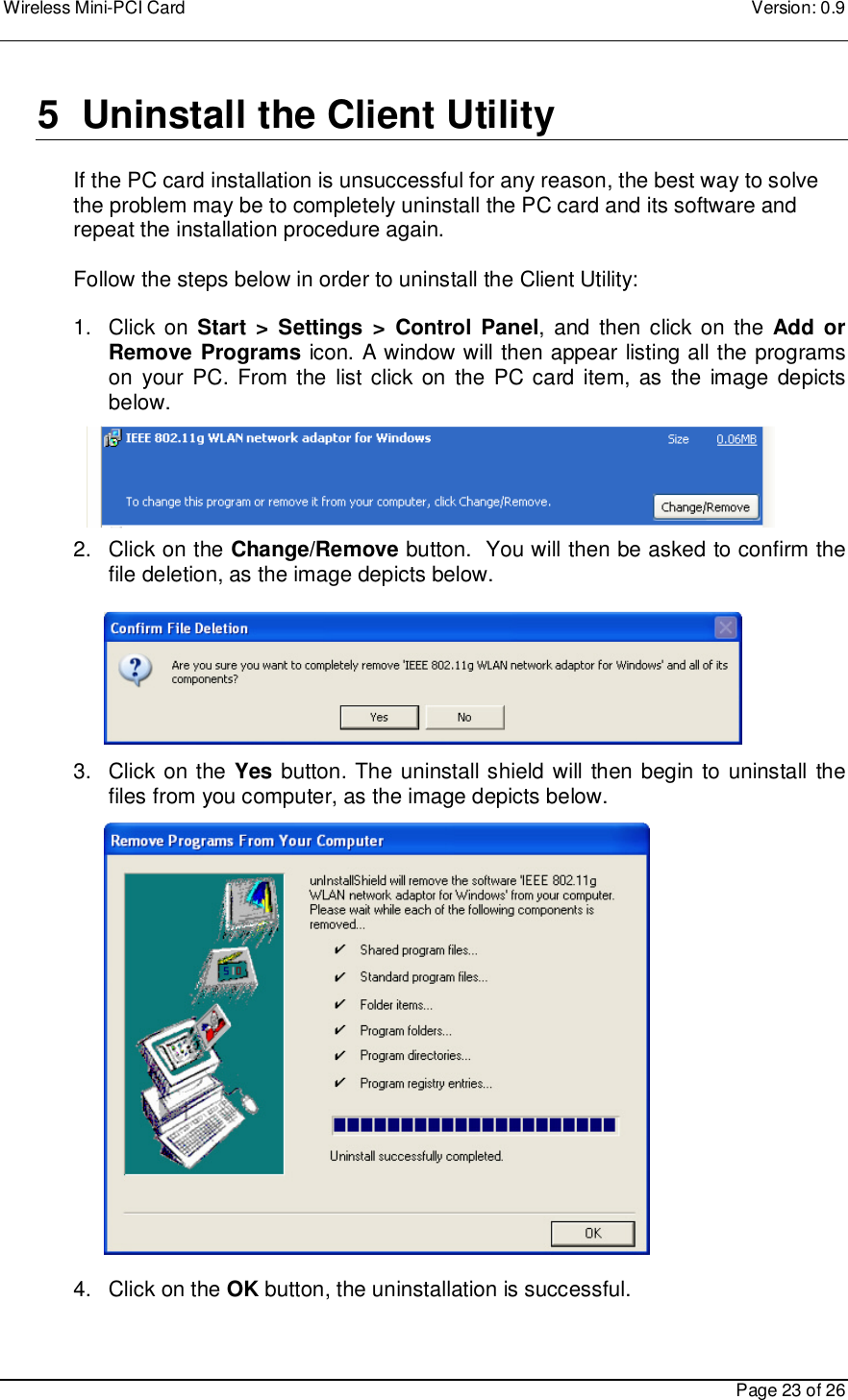
SendFar Technology Co., Ltd. Wireless LAN Card MPI 8540 UsersManual V09
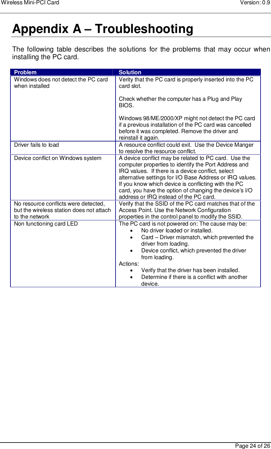
UserManual.wiki
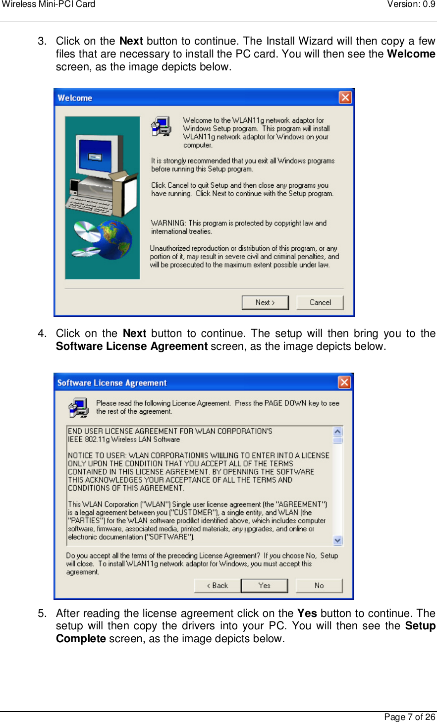
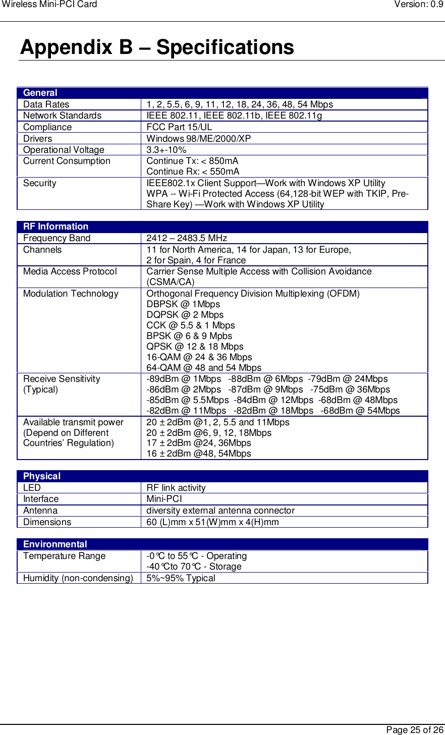
>
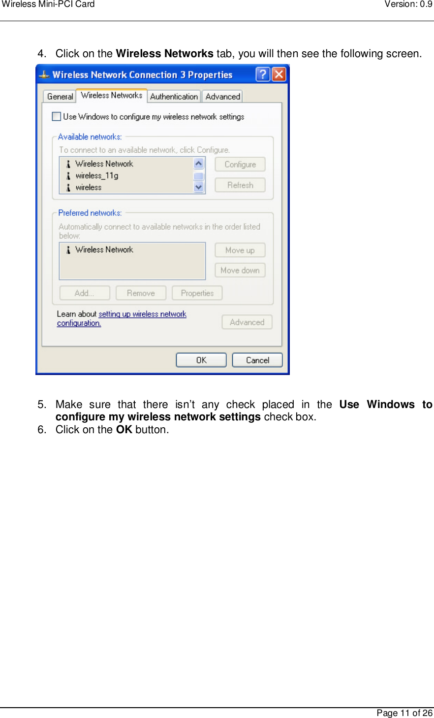
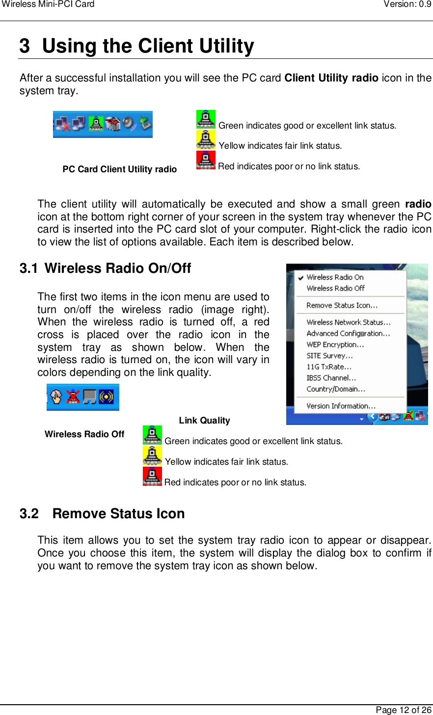
SendFar Technology
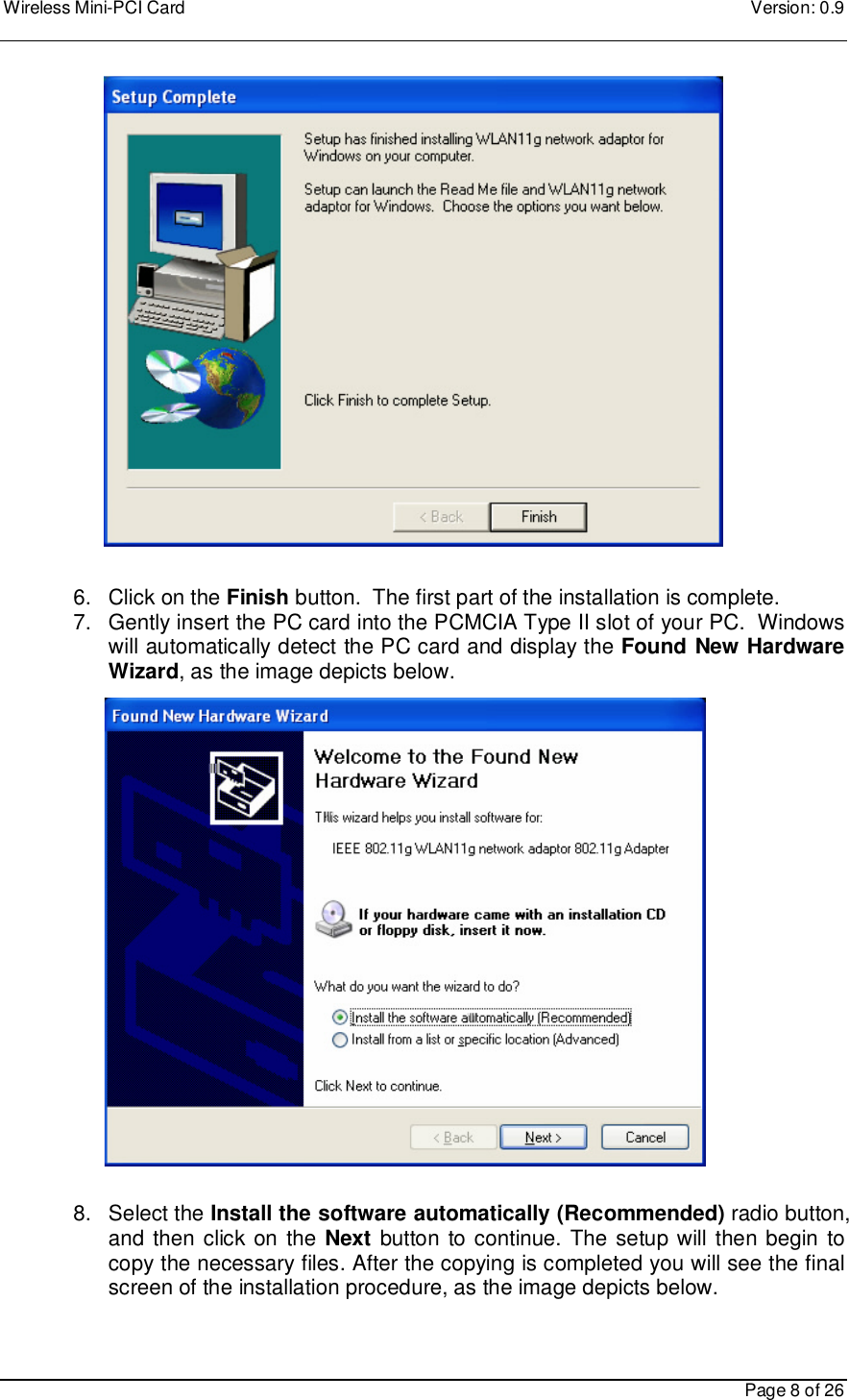
>
MPI-04001 User Manual
>
Users Manual
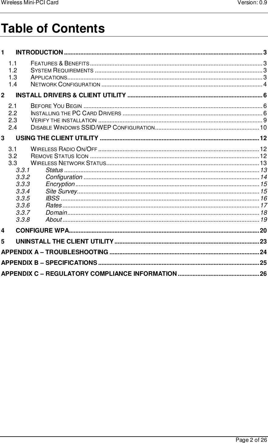
Contents
1.
DoC
2.
Users Manual
Users Manual
Navigation menu
Upload a User Manual
Namespaces
Wiki Guide
HTML
PDF
Info
Views
User Manual
Discussion / Help
Navigation