SendFar Technology ORB-02001 Wireless Router Bridge User Manual Wireless Router Bridge

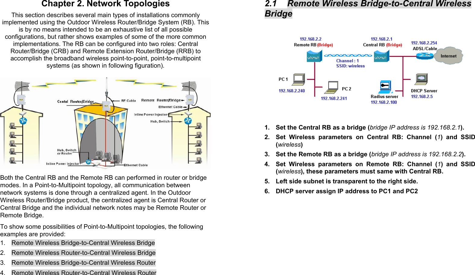
SendFar Technology Co., Ltd. Wireless Router Bridge Wireless Router Bridge

Contents

Users Manual Revised

A    Outdoor Wireless Router/Bridge  User’s Manual   Before operating the unit, please read this manual thoroughly, and retain it for future reference.                i ■  Contents  CHAPTER 1. HARDWARE INSTALLATION ........................................... 1 1.1 BEFORE YOU START ............................................................................. 1 1.2 LOCATE THE ROUTER/BRIDGE AND INLINE POWER INJECTOR PORTS ....... 2 1.3 PREPARING INSTALLATION..................................................................... 3 1.4 OUTDOOR INSTALLATION ....................................................................... 5 1.4.1 Antenna Mast Requirements......................................................... 6 1.4.2 Grounding...................................................................................... 6 1.4.3 Antenna Alignment ........................................................................ 7 CHAPTER 2. NETWORK TOPOLOGIES................................................. 8 2.1 REMOTE WIRELESS BRIDGE-TO-CENTRAL WIRELESS BRIDGE................. 9 2.2 REMOTE WIRELESS ROUTER-TO-CENTRAL WIRELESS BRIDGE.............. 10 2.3 REMOTE WIRELESS BRIDGE-TO-CENTRAL WIRELESS ROUTER.............. 11 2.4 REMOTE WIRELESS ROUTER-TO-CENTRAL WIRELESS ROUTER ............ 12 CHAPTER 3. WEB ACCESS.................................................................. 13 CHAPTER 4. CONFIGURATION............................................................ 17 4.1 INTRODUCTION ................................................................................... 17 4.1.1 Basic Configuration Steps ........................................................... 17 4.2 SYSTEM SETUP................................................................................... 19 AFTER THAT, CLICK FINISH AT THE BOTTOM OF THIS PAGE TO COMPLETE THE MODIFICATION OF THIS PAGE. ......................................................................... 23 AFTER THAT, CLICK FINISH AT THE BOTTOM OF THIS PAGE TO COMPLETE THE MODIFICATION OF THIS PAGE. ......................................................................... 24 AFTER THAT, CLICK FINISH AT THE BOTTOM OF THIS PAGE TO COMPLETE THE MODIFICATION OF THIS PAGE. ......................................................................... 25 4.3 TCP/IP PROTOCOL CONFIGURE.......................................................... 26 4.3.1 Virtual Server Mapping................................................................ 26 4.4 CONFIGURE DHCP SERVER ................................................................ 28 4.4.1 General DHCP Server Parameter............................................... 29 4.4.2 Fixed Host Entries ....................................................................... 29 4.5 CONFIGURE SNMP............................................................................. 31 4.5.1 Configure Community Pool ......................................................... 31 4.5.2 Configure Trap Host Pool............................................................ 32 4.6 CONFIGURE WIRELESS RELATED PARAMETERS..................................... 34 4.7 SECURITY........................................................................................... 36
ii 4.7.1 MAC based Access Control ........................................................ 36 4.8 UTILITY............................................................................................... 37 4.8.1 Software Upgrade ....................................................................... 37 4.8.2 Administration.............................................................................. 38 CHAPTER 5. STATUS MONITOR.......................................................... 39 5.1 SYSTEM INFORMATION ........................................................................ 40 5.2 DHCP INFORMATION .......................................................................... 41 5.3 STATION INFORMATION........................................................................ 42 5.4 STATISTIC INFORMATION ..................................................................... 43 5.5 WIRELESS LINK  INFORMATION ............................................................ 44 CHAPTER 6. SPECIFICATIONS ............................................................ 45 CHAPTER 7. DEFAULT SETTINGS ...................................................... 47 7.1 GENERAL CONFIGURATION .................................................................. 47 7.1.1 System......................................................................................... 47 7.1.2 Virtual Server Mapping................................................................ 48 7.1.3 DHCP .......................................................................................... 49 7.1.4 SNMP .......................................................................................... 50 7.1.5 Wireless LAN............................................................................... 52 7.2 UTILITY............................................................................................... 53 7.2.1 Software Upgrade ....................................................................... 53 7.2.2 Administration.............................................................................. 53 CHAPTER 8. REGULATORY COMPLIANCE INFORMATION............. 54      1 Chapter 1. Hardware Installation This chapter describes the procedures for installing the Outdoor Router/Bridge.  Note: Before you mount the Router/Bridge to a mast or on the side of a building, be sure to configure and test the device first.  1.1  Before You Start After unpacking the system, make sure the following items are present and in good condition.   1. Router/Bridge  2.  Inline Power Injector 3.  AC Power Cord   4.  MIL-C-5015 style RS232 Console Port Cable  5.  Grounding Wire  6.  Cross over Ethernet Cable  7.  Reverse Polarity-N Female RF Cable  8.  30M MIL-C-5015 style Ethernet Cable         9.  Mast Mounting Kit  10.  Wall Mounting Kit  11.  User’s Manual Disk 12. Simple Spanner                 23456789101112
2 1.2  Locate the Router/Bridge and Inline Power Injector Ports    Special Ethernet port 1 for connecting the MIL-C-5015 style Ethernet Cable   Special serial port 2 for connecting the MIL-C-5015 style RS-232 console port cable   Reverse Polarity-N Male connector 3 for connecting the antenna or RF cable.   Grounding port 4.   Power & Data output port 5 for connecting the other of the MIL-C-5015 style Ethernet Cable   Data input port 6 for connecting the Ethernet Cable to a Hub Switch Router or a PC.                            3 1.3 Preparing Installation Before installing your Outdoor Wireless LAN system for your outdoor application in a hard-to-reach location, we recommend that you configure and test all the devices first.  For configuring the Outdoor Router/Bridge, you need follow the quick steps below to power up your Router/Bridge:   Step 1: With the unit powered off, attach one end of the RF cable to the antenna connector and then connect the antenna to the other end of the RF cable as shown in following:                      Step 2 Plug the female end of the power cord into the Inline Power Injector, and then plug the male end of the power cord into a power outlet or power strip. The Power LED on the front of the Inline Power Injector will light up.  Step 3 Run the cross over Ethernet cable (included in your package) from Data Input Port (on the front of the Inline Power Injector) to the Ethernet Port on a PC.  NOTE: This connection is required for setting up initial configuration information. After configuration is completed, this cable will be removed,
4 and then you should run an Ethernet cable from Data Input Port (on the front of the Inline Power Injector) to the LAN connection (such as to a hub, bridge or directly into a patch panel).  Step 4 Plug the MIL-C-5015 style Ethernet connector into the Special Ethernet port on the back of the Router/Bridge.  Step 5 Plug the RJ-45 Ethernet connector (the other end of the Special Ethernet cable) into the Power & Data Output Port on the front of the Inline Power Injector.   Step 6 Attach the MIL-C-5015 style (RS-232) null modem cable to the Serial Port Adapter. Connect the other cable end (DB9 female) to a terminal or a PC running a terminal emulation program.  When the Router/Bridge receives power over the Ethernet cable, the Router/Bridge will start its boot sequence and the Active LED on the front of the Inline Power Injector will light up.  You can configure the Router/Bridge using the HTML browser, such as Internet Explorer or Netscape Navigator from a remote host or PC.    NOTE: The outdoor Router/Bridge antenna cabling systems be identified by Reverse Polarity-N connectors (pictured in following)                5 1.4 Outdoor Installation Outdoor Router/Bridge device can be mounted on the side of a building or mounted to an antenna mast as shown in following:                    A wall (side) mount allows for mounting an antenna (mast) on the side of a building or on the side of an elevator penthouse. This will provide a convenient mounting location when the roof overhang is not excessive and/or the location is high enough to provide a clear line of sight.  In most situations mounting an antenna directly to the wall will not allow you to properly align the antenna with the corresponding antenna at the opposite end of your wireless link. As poor alignment will typically result in poor performance, we advise you to always mount the Outdoor Router/Bridge and antenna to a mast.
6 1.4.1  Antenna Mast Requirements To accommodate the outdoor antennas, the antenna mast must satisfy the following requirements:  a. The construction of the mast must be of a sturdy, weatherproof and no corrosive material like for example galvanized or stainless steel construction pipe.  b. Typical diameter of the mast should be between 35 mm (1.4 in.) and 41 mm (1.625 in.).  Subject to the type of antenna that you intend to install other diameters may be possible as well.  c. The height of the antenna mast must be sufficient to allow the antenna to be installed at least 1.5 m (5 ft.) above the peak of roof. If the roof is metal, then the height of the antenna should be a minimum of 3 m (10 ft) above the roof.  d. The mast or wall-bracket must be free from any substance that may prevent a good electrical connection with the antenna; for example, paint.  1.4.2 Grounding A safety grounding system is necessary to protect your outdoor installation from lightning strikes and the build-up of static electricity. So direct grounding of the antenna mast, Outdoor Router/Bridge and Surge Arrester is very important. The Outdoor Router/Bridge has built in Surge Arrester. So Mounting the Outdoor Router/Bridge on the antenna mast, you have to connect the Outdoor Router/Bridge to the same grounding system with the AC wall outlet.  The grounding system must comply with the National Electrical Code and safety standards that apply in your country. Always check with a qualified electrician if you are in doubt as to whether your outdoor installation is properly grounded.  7 1.4.3 Antenna Alignment  For optimal performance of your wireless link, make sure that the antennas are properly aligned (facing one another “eye-to-eye”). To align the antennas:  _ Use a pair of binoculars and/or a map of the area and compass to point the antennas to one another.  _ Use the Utility- “Wireless Link Info” in the Web Configure as described in the "Utility " section to analyze the radio link quality.  The “Wireless Link Info” will enable you to display the levels of signal strength and link quality. Looking at the Wireless Link Info screen, you can interactively optimize antenna alignment if required, by making small modifications in the antenna orientation.  _ Alternatively, consult a professional Antenna Installation Service to optimize the antenna alignment. Omni-directional antennas are characterized by a wide radiation pattern. Therefore alignment of this type of antennas is less critical than for directional antennas.
8 Chapter 2. Network Topologies This section describes several main types of installations commonly implemented using the Outdoor Wireless Router/Bridge System (RB). This is by no means intended to be an exhaustive list of all possible configurations, but rather shows examples of some of the more common implementations. The RB can be configured into two roles: Central Router/Bridge (CRB) and Remote Extension Router/Bridge (RRB) to accomplish the broadband wireless point-to-point, point-to-multipoint systems (as shown in following figuration).               Both the Central RB and the Remote RB can performed in router or bridge modes. In a Point-to-Multipoint topology, all communication between network systems is done through a centralized agent. In the Outdoor Wireless Router/Bridge product, the centralized agent is Central Router or Central Bridge and the individual network notes may be Remote Router or Remote Bridge. To show some possibilities of Point-to-Multipoint topologies, the following examples are provided: 1.  Remote Wireless Bridge-to-Central Wireless Bridge  2.  Remote Wireless Router-to-Central Wireless Bridge 3.  Remote Wireless Bridge-to-Central Wireless Router 4.  Remote Wireless Router-to-Central Wireless Router  9 2.1  Remote Wireless Bridge-to-Central Wireless Bridge   1.  Set the Central RB as a bridge (bridge IP address is 192.168.2.1). 2.  Set Wireless parameters on Central RB: Channel (1) and SSID (wireless) 3.  Set the Remote RB as a bridge (bridge IP address is 192.168.2.2). 4.  Set Wireless parameters on Remote RB: Channel (1) and SSID (wireless), these parameters must same with Central RB. 5.  Left side subnet is transparent to the right side. 6.  DHCP server assign IP address to PC1 and PC2
10 2.2  Remote Wireless Router-to-Central Wireless Bridge  1.  Set the Central RB as a bridge (bridge IP address is 192.168.2.1). 2.  Set Wireless parameters on Central RB: Channel (1) and SSID (wireless). 3.  Set the Remote RB as a Router (Wireless Interface IP is 192.168.2.2, Ethernet Interface IP is 192.168.10.1, must turn on NAT on Wireless Interface, default route is 192.168.2.254). 4.  Set Wireless parameters on Remote RB: Channel (1) and SSID (wireless), these parameters must same with Central RB. 5.  Set the DHCP server service on the Remote RB and apply it on Ethernet Interface. 6.  The Remote RB assign IP address to PC1 and PC2    11 2.3  Remote Wireless Bridge-to-Central Wireless Router  1.  Set the Central RB run as a Wireless Router (Wireless Interface IP is 192.168.1.1, Ethernet Interface IP is 192.168.2.1, must turn on NAT on Ethernet interface, default route is 192.168.2.254). 2.  Set Wireless parameters on Central RB: Channel (1) and SSID (wireless) 3.  Set the DHCP server service on the Central RB and apply it on Wireless Interface. 4.  Set the Remote RB as a Bridge (Bridge Interface IP is 192.168.1.2).  5.  Set Wireless parameters on Remote RB: Channel (1) and SSID (wireless), these parameters must same with Central RB. 6.  The Central RB assign IP address to PC1 and PC2 7.  The operator can also turn off NAT behavior on Central RB and two subnets are transparent.
12 2.4  Remote Wireless Router-to-Central Wireless Router  1.  Set the Central RB run as a Wireless Router (Wireless Interface IP is 192.168.1.1, Ethernet Interface IP is 192.168.2.1, default route is 192.168.2.254). 2.  Set Wireless parameters on Central RB: Channel (1) and SSID (wireless). 3.  Set the Remote RB as a Wireless Router (Wireless Interface IP is 192.168.1.2, Ethernet Interface IP is 192.168.10.1, default route is 192.168.1.1).  4.  Set Wireless parameters on Remote RB: Channel (1) and SSID (wireless), these parameters must same with Central RB. 5.  Set the DHCP server service on the Remote RB and apply it on Ethernet Interface. 6.  The Remote RB assigns IP address to PC1 and PC2. The operator can also turn off NAT behavior on Central RB and turn on NAT behavior on Remote RB. In this case, any outgoing packets will transfer to 192.168.1.2   Remote RB: turn on NAT on Wireless Interface. The operator can also turn on NAT behavior on Central RB and turn on NAT behavior on Remote RB.   Central RB: turn on NAT on Ethernet interface.   Remote RB: turn on NAT on Wireless Interface.  13 Chapter 3. Web Access  Web Connection  The SendFar Outdoor Wireless Access Router/Bridge (RB) supports access to the configuration system through the use of an HTTP Interface (web browser). Before configuring the RB, you need to know the IP Address assigned to the unit.  When shipped from the factory, the IP Address (192.168.2.1) was assigned to the RB by default. To start a web connection use:   http://192.168.2.1/   Identify the IP Address assigned to the unit   However, the IP Address may be changed and you cannot connect the unit using the default IP Address. In this case, you must identify the RB IP Address before configuration. To identify the IP Address, you can use the Serial Port to gain access the current network status. To start a Serial Port connection:  1.  Attach a serial data (RS-232) cable to the Serial Port Adapter. Connect the other cable end to a terminal or a PC running a terminal emulation program. Use a 9-pin female to 9-pin female NULL Modem cable. 2.  Set the terminal to 115200 Baud, No-Parity, 8 data bits, 1 Stop bit, and ANSI compatible.  Note: Running a terminal emulation program on your PC, such as HyperTerminal, and then set the following connection properties:    Click the Start icon > Program > Accessories > Communication > Terminal.    Create a new connection file, and then select a Com Port <COM1, COM2, etc., depending on your PC> with 115200bps / 8-bits / 1-stop.    Click the properties icon in the Tool Bar > setting > select Emulation terminal VT100 > ok.
14 3.  Reboot or turn on your RB 4.  When the RB is powered up, the “Current Network Status” will be displayed.   Figure 3-1   Current Network Status   Web Access Procedure  Once you identify the IP Address assigned to your OWRB, use your web browser to configure the OWRB through the HTTP Interface.  The following procedure explains how to configure each item. 1.  Open your browser and enter the IP Address 2. Press ENTER and the RB Login screen appear.               15 Figure 3-2   Login Screen  3. Enter root in the User Name and the Password fields. And then the web configuration user interface screen appears.                       Figure 3-3    Web User Interface   Web Configuration Structure  The web configuration user interface be grouped in a tree structure, and contains the following settings or information:   ▽  General Configuration ●  System ●  TCP/IP - Virtual Server - DHCP - SNMP ●  Wireless ●  Security - MAC Filter
16  ▽  Running Status ●  System Info ●  DHCP Info ●  Station Info (Central RB only) ●  Statistic Info ●  Wireless Link Info (Remote Extension RB only)  ▽  Utility ●  Software Upgrade ●  Administration  Move through the tree by clicking on an icon to expand or collapse the tree. The nodes on the tree represent web pages that allow you to view and modify the parameters.                      Figure 3-4  Web Configuration Structure  17 Chapter 4. Configuration 4.1 Introduction  What you Need to Know  The RB can be configured into two operation roles: Central Wireless Router/Bridge (Central RB) and Remote Wireless Router/Bridge (Remote RB). Central RB can performed in four operation modes: •  Central Wireless Bridge •  Central Wireless Router with PPPoE Ethernet connection •  Central Wireless Router with dynamic IP address Ethernet •  Central Wireless Router with static IP address Ethernet Remote RB can performed in two operation modes: •  Remote Wireless Bridge •  Remote Wireless Router  The RB is shipped with default configuration is as a bridge between an Ethernet and wireless network. Users simply need to attach the RB to your wired LAN. If users would like to configure the RB, please refer to the following procedures.   4.1.1 Basic Configuration Steps  Modify the Default Settings and Apply the New   This section will describe a 5-step configuration to setup your Outdoor Wireless Router/Bridge (RB) workable.  1.  Select an operation mode for your RB on the web page “/General Config/System/”, and click  FINISH  to refresh this page.
18 2.  Modify the factory-set default parameters on the web page “/General Config/System/”page, and click  FINISH  to save your changes. 3.  Modify the factory-set default parameters on the web page “/General Config/Wireless/”page, and click  FINISH  to save your changes. 4.  (Optional) Modify others parameters on the web page “/General Config/”page, and click  FINISH  to save your changes. 5.  Move on page “/Utility/Administration/”, select the Save then Restart and then click  FINISH  to take effect the previous configuration changes. 19 4.2 System Setup When setting up a SendFar Wireless Router/Bridge (RB), you must decide which operation mode that your RB works. This feature is available in the “/General Config/System/” page.   Figure 4-1 & 4-2 show the “General Configuration – System Setup” page.                      Figure 4-1 General Configuration – System Setup-1
20                  Figure 4-2  General Configuration – System Setup-2   Host Information  - Host Name. The Host Name is not an essential setting, but it helps identify the device in network.  Use this setting to assign a name to the device.   Operation Mode The First Thing You Have To Do Select an operation mode, and click FINISH  to refresh this page.  Central Bridge  Select the Central Wireless Bridge mode. And then set the corresponding parameters.   - Bridge IP Address.  Use this setting to assign or change the bridge’s IP address.  21 - Bridge Subnet Mask. Enter an IP subnet mask to identify the sub network so the IP address can be recognized on the LAN.  Default Route IP  - IP Address. Enter the default Gateway IP Address.  After that, click FINISH at the bottom of this page to complete the modification of this page.   Remote Extension  Bridge  Select the Remote Wireless Bridge mode. And then set the corresponding parameters.   - Bridge IP Address.  Use this setting to assign or change the bridge’s IP address.  - Bridge Subnet Mask. Enter an IP subnet mask to identify the sub network so the IP address can be recognized on the LAN.  Default Route IP  - IP Address. Enter the default Gateway IP Address.  After that, click FINISH at the bottom of this page to complete the modification of this page.   Central Router with PPPoE Client Ethernet connection  If you are an ADSL subscriber, you need to specify that you personal ISP PPPoE Username and Password to enable ADSL broadband access.   - PPPoE User Name. This setting allows you to enter the user name that your ISP assigns to your account.  - PPPoE Password. Enter the password that your ISP assigns to your account.  - Password Confirm. Enter the PPPoE Password once more again.
22 Wireless Interface Address  - IP Address. Use this setting to assign or change the wireless interface’s IP address.  - Subnet Mask. Enter an IP subnet mask to identify the sub network so the IP address can be recognized on the WLAN.  Ethernet Interface Address  - IP Address. Use this setting to assign or change the Ethernet interface’s IP address  - Subnet Mask. Enter an IP subnet mask to identify the sub network so the IP address can be recognized on the WAN.  NAPT performs on which interface? There are three interfaces. You can select one to use or select "None" to disable it. Default Route IP  - IP Address. Enter the default Gateway IP Address.  DNS Server IP  - Primary DNS Server IP. Enter the Primary Domain Name Server IP Address.  - Secondary DNS Server IP.  Enter the Secondary Domain Name Server IP Address.  After that, click FINISH at the bottom of this page to complete the modification of this page.   Central Router with DHCP Client Ethernet connection   Wireless Interface Address  - IP Address. Use this setting to assign or change the wireless interface’s IP address.  23 - Subnet Mask. Enter an IP subnet mask to identify the sub network so the IP address can be recognized on the WLAN.  NAPT performs on which interface? There are three interfaces. You can select one to use or select "None" to disable it. Default Route IP  - IP Address. Enter the default Gateway IP Address.  DNS Server IP  - Primary DNS Server IP. Enter the Primary Domain Name Server IP Address.  - Secondary DNS Server IP.  Enter the Secondary Domain Name Server IP Address. After that, click FINISH at the bottom of this page to complete the modification of this page.  Wireless Router with static IP Ethernet connection   Wireless Interface Address  - IP Address. Use this setting to assign or change the wireless interface’s IP address.  - Subnet Mask. Enter an IP subnet mask to identify the sub network so the IP address can be recognized on the WLAN.  Ethernet Interface Address  - IP Address. Use this setting to assign or change the Ethernet interface’s IP address  - Subnet Mask. Enter an IP subnet mask to identify the sub network so the IP address can be recognized on the WAN.  NAPT performs on which interface? There are three interfaces. You can select one to use or select "None"
24 to disable it. Default Route IP  - IP Address. Enter the default Gateway IP Address.  DNS Server IP  - Primary DNS Server IP. Enter the Primary Domain Name Server IP Address.  - Secondary DNS Server IP.  Enter the Secondary Domain Name Server IP Address. After that, click FINISH at the bottom of this page to complete the modification of this page.   Remote Extension Router   Wireless Interface Address  - IP Address. Use this setting to assign or change the wireless interface’s IP address.  - Subnet Mask. Enter an IP subnet mask to identify the sub network so the IP address can be recognized on the WLAN.  Ethernet Interface Address  - IP Address. Use this setting to assign or change the Ethernet interface’s IP address  - Subnet Mask. Enter an IP subnet mask to identify the sub network so the IP address can be recognized on the WAN.  NAPT performs on which interface? There are three interfaces. You can select one to use or select "None" to disable it. Default Route IP  - IP Address. Enter the default Gateway IP Address.  25 DNS Server IP  - Primary DNS Server IP. Enter the Primary Domain Name Server IP Address.  - Secondary DNS Server IP.  Enter the Secondary Domain Name Server IP Address. After that, click FINISH at the bottom of this page to complete the modification of this page.
26 4.3  TCP/IP Protocol Configure 4.3.1  Virtual Server Mapping  Sometimes, the operator can expose the internal servers on the local intranet to the public Internet. For this, you must create the Virtual Server Mapping for these invisible internal servers.  Select the “/General Config/ Virtual Server/”, and then the General Configuration - Virtual Server screen appears.  Figure 4-3 show the current virtual server entry table. (Default Virtual Server Mapping pool is empty)                     Figure 4-3 General Configuration - Virtual Server  1. Click  Add . The Virtual Server Entry Edit page Figure 4-4 appears. 2.  To edit the Virtual Server Entry, specify all the entry fields to allow Internet user to access the Internal servers.  Service Name: Alias name of this internal server, such as FTP. 27 Access Interface: Indicate the translation occurs on which interface (Wireless interface / Ethernet interface), such as Ethernet. Protocol: Indicate which protocol (TCP/UDP) you want to translate from outside to internal server, such as TCP. Public Access Port number: Indicate which socket port (1 ~ 65535) you want to translate from outside to internal server, such as 21. Virtual Server IP address: Specify the private IP address of the internal server, such as 192.168.1.100. Virtual Server Port number: Specify the socket port (1 ~ 65535) of the internal server, such as 21. 3. Click  OK . The Virtual Server Entry Table appears with the entries list. 4.  To modify or delete a virtual server entry, click the select button beside the entry index number and click  Modify  or  Delete .  5.  To add another entry to the Virtual Server Mapping Pool, repeat step 1 through step 3.   6.  When you have included all the entries you need, click  FINISH .                       Figure 4-4     Add Virtual Server Entry
28 4.4  Configure DHCP server Sometimes, the operator want to managing a large TCP/IP network requires maintaining accurate and up-to-date IP address and domain name information. In this situation, it needs manually configure and enable the DHCP server service. Select the “/General Config/ DHCP/”, and then the General Configuration – DHCP Parameter screen appears.  Figure 4-5 shows the general DHCP parameters and the fixed host entry table. (Default fixed host entry pool is empty).                     Figure 4-5   DHCP Parameter         29 4.4.1 General DHCP Server Parameter  - Trigger DHCP Service. Select Enable to allow the RB to assign IP Addresses from IP Pool Table. Select Disable to prevent IP Address assignment from the RB  - Default Gateway. Enter the default Gateway IP Address.   - Subnet Mask. Configure the subnet for the client.   - Name Server 1, 2, 3. Configure the DNS servers IP for the client.  - DHCP Start IP address. Enter the starting IP Address for this IP Pool Table.   - DHCP End IP address.  Enter the ending IP Address for this IP Pool Table.   - Apply Interface. Enable DHCP server service on Wireless or Ethernet interface.    4.4.2  Fixed Host Entries Figure 4-5 shows the general DHCP parameters and the fixed host entry table. (Default fixed host entry pool is empty).  1. Click  Add . The Fixed Host Entry Edit page Figure 4-6 appears. 2.  To edit the Fixed Host Entry, specify the Ethernet and Internet Address fields.  - Ethernet Address. Enter the MAC address for a fixed IP user.  - Internet Address. Assign a fixed IP Address to this special user.   3. Click  OK . The Fixed Host Entry Table appears with the entries list. 4.  To modify or delete a fixed host entry, click the select button beside the entry index number and click  Modify  or  Delete .
30 5.  To add another entry to the Fixed Host Mapping Pool, repeat step 1 through step 3. 6.  When you have included all the entries you need, click  FINISH .                     Figure 4-6   Add Fixed Host Entry        31 4.5 Configure SNMP Click General Config, SNMP, and then the General Configuration – SNMP Community Parameter screen appears.  Figure 4-7 shows the current SNMP community pool and trap host pool.                       Figure 4-7  General Configuration – SNMP Community Parameter   4.5.1  Configure Community Pool The SNMP Community Pool has five entries.   1.  To modify a entry, click the select button beside the entry index number and then click  Modify , the configuration page Figure 4-8 appears. 2.  Specify the Validity, Access Right and Community field.  - Validity. Select Enable or Disable to control this community.
32 - Access Right. Select a command from the pull down menu for this field.   - Community. Enter the password related the Access Right in this field.   3. Click  OK . To refresh the current community pool. 4.  To modify another community entry to the current community pool, repeat step 1 through step 3. 5.  When you have modified all the entries you need, click  FINISH .                         Figure 4-8  Modify SNMP Community Parameter   4.5.2  Configure Trap Host Pool The Trap Host Pool has five entries.   1.  To modify a entry, click the select button beside the entry index number and click  Modify  . The configuration page Figure 4-9 appears. 33 2.  Specify the Version, IP Address and Community field.  - Version. Select Disable, Version 1 or Version 2 to control this trap host.   - IP Address. Enter the Trap Host IP Address.   - Community. Enter the password in this field.   3. Click  OK . To refresh the current trap host pool. 4.  To modify another trap host entry to the current trap host pool, repeat step 1 through step 3. 5.  When you have modified all the entries you need, click  FINISH .                        Figure 4-9  Modify SNMP Trap Host Parameter
34 4.6  Configure Wireless related parameters  Click General Cofig, Wireless. The Wireless LAN information page Figure 4-10 appears. In here, enter the Channel (default is 1), rts Threshold (default is 1600), frag Threshold (default is 1600), SSID (default is wireless) and Station Name (default is ap) that are suitable for your radio network and then you can clicked radio button to disable WEP or enable 64/128 bit WEP services (default is disable), if WEP is enabled, you must input corresponded Default Key index and WEP Key and then click  KeyGen  to generate the WEP64 & WEP128 key patterns. After that, click FINISH at the bottom of this page to complete the modification.                      Figure 4-10   - Channel. The factory setting is Radio Channel 1 transmitting at 2412 MHz. The channel set appears on the screen installed on your access. Each channel covers 22 MHz. The bandwidth for channels 1, 6, and 11 does not overlap, so you can set up multiple access point in the same vicinity without causing interference.  - RTS Threshold. This setting determines the packet size at which the 35 bridge issues a request to send (RTS) before sending the packet. A low RTS Threshold setting can be useful in areas where many client devices are associating with the access point, or in areas where the clients are far apart and can detect only the bridge and not each other. Enter a setting ranging from 0 to 2339 bytes.  - Frag Threshold. This setting determines the size at which packets are fragmented (sent as several pieces instead of as one block). Enter a setting ranging from 256 to 2338 bytes. Use a low setting in areas where communication is poor or where there is a great deal of radio interference.  - SSID. The Service Set ID (SSID) can be any alphanumeric, case-sensitive entry from two to 32 characters long. This string functions as a password to joint the radio network.  - Hide SSID. You use this setting to choose whether devices that do not specify an SSID are allowed to associate with the access point. With Yes selected, the SSID used by other devices must match exactly the AP’s SSID.  - Deny Any. You use this setting to choose whether devices that specify the well define SSID keyword ‘ANY’ or ‘any’ are allowed to associate with the access point. With Yes selected, the SSID ‘ANY’ or ‘any’ used by other devices are not allowed to associate with the access point   - Station Name. Enter any alphanumeric, case-sensitive entry.   - WEP Key. Enter 1~15 characters for 64 and 128 bits WEP KEY encryption, and then click  KeyGen  to generate the WEP64 & WEP128 key patterns.  - WEP. Disable or enable 64/128 bit WEP services.  - Default Key. Select an encryption key from the pull down menu.   - WEP64 Key1~4 & WEP128 Key1~4. The keys in these fields can be generated automatically by  KeyGen  function. For 40-bit encryption, enter 10 hexadecimal digits; for 128-bit encryption, enter 26 hexadecimal digits. Hexadecimal digits include the numbers 0 through 9 and the letters A through F. Your 40-bit WEP keys can contain any combination of 10 of these characters; your 128-bit WEP keys can contain any combination of 26 of these characters. The letters are not case-sensitive.
36 4.7 Security   4.7.1  MAC based Access Control  1. Click Basic Config, select MAC Filter page, and choice the MAC Filter services is Enable or Disable (as shown in Figure 4-11). 2.  You can specify the MAC address of a wireless client station. All MAC entries in the MAC address table are permitted to connect into the RB. You can also click ADD, DELETE, MODIFY button to maintain this MAC address table. After that, click FINISH at the bottom of this page to complete the modification of this page.                Figure 4-11   37 4.8  Utility   4.8.1 Software Upgrade 1. Click Utility, select Software Upgrade page (as shown in Figure 4-12), and then you can use TFTP to upgrade your AP. In here, you must specify the TFTP server IP and select which file you want to upgrade it (Program image, Web image), then click OK button to start the TFTP upgrade process.  2.  If the upgrade process is success, the AP will apply the new settings and start rebooting right away.   Hint: You must set up a TFTP server and this server must contain one latest new image.                      Figure 4-12
38 4.8.2 Administration Click Utility, Administration. Figure 4-13 shows the Utility – Administration page.                        Figure 4-13   Utility – Administration  Supervisor Account Change the supervisor’s user name & password in the Supervisor Account field, and Click FINISH. To take effect the previous configuration changes.  Apply the New Settings 1. Click Utility, Administration, select the Save then Restart to apply the new configuration settings. 2. Click FINISH. To take effect the previous configuration changes. Hint: It takes about 10 seconds, to complete the restart process.      39 Chapter 5. Status Monitor You can see the system running status and the some information on this windows. Click the Running Status link on the left window (as shown in Figure 5-1), you can choose which function that you want to monitor.                       Figure 5-1   Running Status
40 5.1 System Information Click Running Status, System Info. Figure 5-2 shows the System Information page.                        Figure 5-2   Running Status – System Info  In this page, you can see the system information and most running parameters.  General System Information This block displayed the Product Model, Host Name, Software Version, Build, Boot Code Version, Web Version, AP Firmware version and System Uptime.    General System Status This block displayed the Operation Mode, Interface IP/Net mask and brief wireless parameters, if the operator turn on the DHCP or PPPoE services, you can also see the related information on here.  Services Information This block displayed which service is turn on or not. It is includes the NAPT, DHCP server, SNMP, 802.1x access control, MAC Filter and WEP encryption.  41  5.2 DHCP Information Click Running Status, DHCP Info. Figure 5-3 shows the DHCP assigned IP Information page.                       Figure 5-2   Running Status – DHCP Info  In this page, you can see the DHCP server assigned table, includes MAC address, corresponded IP address and IP assigning type (Dynamic or Fix).
42   5.3 Station Information This item only displayed on Central RB mode. Click Running Status, Station Info. Figure 5-3 shows the associated stations information page.                       Figure 5-3   Running Status – Station Info  In this page, you can see how many wireless stations associated to this AP, this association table includes the associated station MAC address and the corresponded connection time.          43    5.4 Statistic Information Click Running Status, Statistic Info. Figure 5-3 shows the statistic of interface page.                       Figure 5-4   Running Status – Statistic Info  In this page, you can see the packet statistic of each interface, Wireless and Ethernet. This statistic table includes the In Packets, Out Packets, In Bytes and Out Bytes.
44     5.5  Wireless Link  Information This item only displayed on Remote RB mode. Click Running Status, Wireless Link Info. Figure 5-3 shows the Radio Link information page.                       Figure 5-5   Running Status – Wireless Link Info  In this page, you can see four information about this radio link: Link Quality, Signal Strength, Current used channel and Current Tx Rate.    45 Chapter 6. Specifications General Compatibility  Fully interoperable with IEEE802.11b compliant products Regulation Certifications  FCC Part 15, ETSI 300/328 Power Supply   Output: DC 5V/3A Input: 100/240 VAC; 50/60 Hz Temperature Range   0 to 55 ℃ (operating)  -20 to 75 ℃ (storage) Humidity (non-condensing)  10% ~ 90% Interface LAN ports:  3 Switching (10Base-T/100Base-TX)  WAN port: 1  (10Base-T/100Base-TX) Console port: RS-232 x 1  Radio Frequency Band   2.4 – 2.484 GHz Radio Type  Direct Sequence Spread Spectrum (DSSS) Modulation   CCK (11, 5.5Mbps)  DQPSK (2Mbps) DBPSK (1Mbps) Operation Channels   11 for North America, 14 for Japan,  13 for Europe Receiver Sensitivity  -84dBm for 11Mbps @ 8% PER (Packet Error Rate) -90dBm for 2Mbps @ 8% PER (Packet Error Rate) RF Output Power   19dBm typically (including antenna gain), ETSI 18.6dBm typically (including antenna gain), FCC RF Connector  Reversed N Type
46 Network Information Protocol Supported  TCP/IP NAT/NAPT Virtual Server DHCP client DHCP server PPPoE Bridge   Security  PPP PAP/CHAP/MS-CHAP Authentication in Web-Based manager IEEE 802.1x Port-Based network access control Radius client (Authentication & Accounting) MAC address based access control 64-bit, 128-bit WEP encryption 802.11 SSID hidden Denial 802.11 “Any” station  Management Local Configuration   RS-232 serial port Remote Configuration  HTTP, SNMP Firmware Upgrade  Upgrade via Serial Interface or TFTP  Physical Specifications Dimensions   211(L) mm x 151(W) mm x 40(H) mm Weight  1000 g 47 Chapter 7.  Default Settings 7.1 General Configuration 7.1.1 System  Parameter Description Default Value  Host Name   Host name for the RB  HWLAN  Operation Mode 1. Central Bridge 2. Remote Extension Bridge 3.  Central Router with PPPoE client Ethernet connection  4.  Central Router with DHCP client Ethernet connection 5.  Central Router with Static IP Ethernet connection 6.  Remote Extension Router Central Bridge Bridge IP Address 192.168.2.1 Bridge Subnet Mask For CRB /RRB with Bridge Operation Mode  255.255.255.0 PPPoE User Name  user PPPoE Password  pass Password Confirm For Central Router with PPPoE client Ethernet connection only    pass IP Address  192.168.1.1 Wireless Interface Address  Subnet Mask  255.255.255.0 IP Address  192.168.2.1 Ethernet-WAN Interface Address  Subnet Mask  255.255.255.0 IP Address  192.168.2.1 Ethernet-LAN Interface Address  Subnet Mask  255.255.255.0 NAPT Interface  1. None 2. Wireless LAN  None
48 3. Ethernet 4. PPPoE  Default Route IP  IP address of the gateway for   default route when TCP/IP    filtering 192.168.2.254 Primary DNS Server IP  192.168.2.254 Second DNS Server IP IP addresses of the DNS Servers of your Local ISP     7.1.2  Virtual Server Mapping  Parameter Description Default Value  Service Name  Specify the service for public access  NULL  Protocol  Select a protocol for public  access  NULL Interface  NULL  Public Access  Port Number  NULL IP address  NULL  Virtual Server  Port Number  NULL Note: (Maximum Entry: 10, Maximum Port Number: 32767)  49 7.1.3  DHCP Parameter Description Default Value  Trigger DHCP Service Disable or Enable automatic IP address assignment to wireless stations Disable  Default Gateway IP address of the gateway for  default route when TCP/IP filtering 192.168.1.1 Net Mask Consists of four sets of digits that help divide a network into sub-networks and simplify routing and data transmission 255.255.255.0 Name Server 1:  192.168.2.254 Name Server 2:  Null Name Server 3:  IP address of the DNS host Null  DHCP Start IP   IP starting address  192.168.1.240  DHCP End IP   IP ending address  192.168.1.249  Interface  1. Wireless 2. Ethernet  Wireless Ethernet Address  Fixed Host Entries  (Max 10)  IP Address  Empty
50 7.1.4 SNMP  7.1.4.1  Table of SNMP Community Pool: Parameter Description Default Value Index 1  Enable Index 2 Enable Index 3 Disable Index 4 Disable Index 5 Validity  Enable or disable the function   of the corresponding community  index Disable Index 1  Read Index 2 Write Index 3 --- Index 4 --- Index 5 Access Right  Select the access right  (Deny/Read/Write/Create) for   SNMP Manager --- Index 1  public Index 2 private Index 3 --- Index 4 --- Index 5 Community  Specify the type of community   (public or private) for SNMP  Manager ---    51 7.1.4.2  Table of SNMP Trap Community Host Pool: Parameter Description Default Value Index 1  Version1 Index 2 Version2 Index 3 --- Index 4 --- Index 5 Version  Select or disable the SNMP   Version  Version 1:  MIB1  Version 2:  MIB2 --- Index 1  192.168.2.100 Index 2 192.168.2.100 Index 3 --- Index 4 --- Index 5 IP Address  Specify the IP address of the   SNMP Manager for SNMP Trap  Report --- Index 1  public Index 2 public Index 3 --- Index 4 --- Index 5 Community  Specify the type of community   (public or private) for SNMP  Manager ---
52 7.1.5  Wireless LAN  Parameter   Description Default Value  Regulatory Domain  Define the regulatory domain to  Which this NIC may be deployed  1  Channel   USA: 1~11, Europe: 1~13  1  RTS Threshold   Set RTS (Request To Send)   threshold value  1600  Fragmentation  Threshold  Set fragmentation threshold   value  1600  SSID  Wireless LAN service area   identifier of the RB (case   sensitive) wireless  Hide SSID   Yes or No  No  Deny ANY   Yes or No  No  Station Name   Show the name of the AP  ap  WEP Key  Push the “KeyGen” button to generate the WEP key patterns automatically wepkey  WEP 1. WEP128 2. WEP64 3. Disable Disable  Default Key  Select a WEP key to encrypt   each frame transmitted from   the radio using one the of the 4  Keys from the Key Panel 1  Key Panel  When you use WEP to  communicate with the other   wireless clients, all the wireless  devices in this network must   have the same encryption key  or pass phrase.  Note: each key must consist  of hex digits, it means that   only digit 0 -9 and letters A-F  53  are valid entries. If entered  incorrectly, program will not  write keys to a driver. 7.2 Utility 7.2.1  Software Upgrade Parameter Description Default Value  TFTP Server IP  Address  Specify the IP address of the   TFTP server to upgrade the   firmware of  the RB 192.168.2.100  Program Image  soho.bin  Upgrade Filename  Web Image  pfs.img  7.2.2 Administration Parameter Description Default Value  Supervisor ID   Supervisor’s identity code  root  Supervisor Password   Supervisor’s password  root  Password Confirm   Confirm the password again  root
54 Chapter 8. Regulatory Compliance Information  Radio Frequency Interference Requirements This device complies with Part 15 of FCC Rules and Canada RSS-210. Operation is subject to the following conditions: This device may not cause harmful interference. This device must accept any interference received, including interference that may cause undesired operation.  Radiation Exposure Statement This equipment complies with FCC radiation exposure limits set forth for an uncontrolled environment. This equipment should be installed and operated with minimum distance 20 cm between the radiator & your body.  This transmitter must not be co-located or operating in conjunction with any other antenna of transmitter.  Interference Statement This equipment has been tested and found to comply with the limits for a Class B digital device pursuant to Part 15 of the FCC Rules and Regulation. These limits are designed to provide reasonable protection against harmful interference in a residential installation. This equipment generates, uses, and can radiate radio frequency energy and, if not installed and used in accordance with the instruction manual, may cause harmful interference to nearby TV’s, VCR’s, radio, computers, or other electronic devices. To minimize or prevent such interference, this equipment should not be placed or operated near these devices. If interference is experienced, moving the equipment away from them will often reduce or eliminate the interference.  However, there is no guarantee that interference will not occur in a particular installation. If the equipment does cause harmful interference to radio or television reception, which can be determined by turning the equipment off and on, the user is encouraged to try to correct the interference by one or more of the following measures: Re-orient or relocate the receiving antenna. Increase the separation between the equipment and receiver. Connect the equipment into an outlet on a circuit different from that which the receiver is connected. Consult the dealer or an experienced radio/TV technician for help.   55 Professional Installation Per the recommendation of the FCC, the installation of high gain directional antenna to the system, which are intended to operated solely as a point-to-point system and whose total power exceeds +30dBm EIRP, require professional installation. It is the responsibility of the installer and the end user that the high power systems are operated strictly as a point-to-point system. Systems operating as a point-to-multipoint system or use non directional antennas cannot exceed +30dBm EIRP power requirement under any circumstances and do not require professional installation.             Information to userThe user manual or instruction manual for an intentional orunintentional radiator shall caution the user that changes or modifications not expressly approved bythe party responsible for compliance could void the user's authurity to operatethe equipment.

Navigation menu