Siemens Canada Siemens Milltronics Process Instruments LR250 SITRANS LR 250 TANK LEVEL PROBING RADAR User Manual JE01 LR250 LUI
Siemens Canada Ltd. - Siemens Milltronics Process Instruments SITRANS LR 250 TANK LEVEL PROBING RADAR JE01 LR250 LUI
Contents
USERS MANUAL

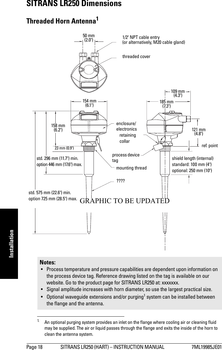
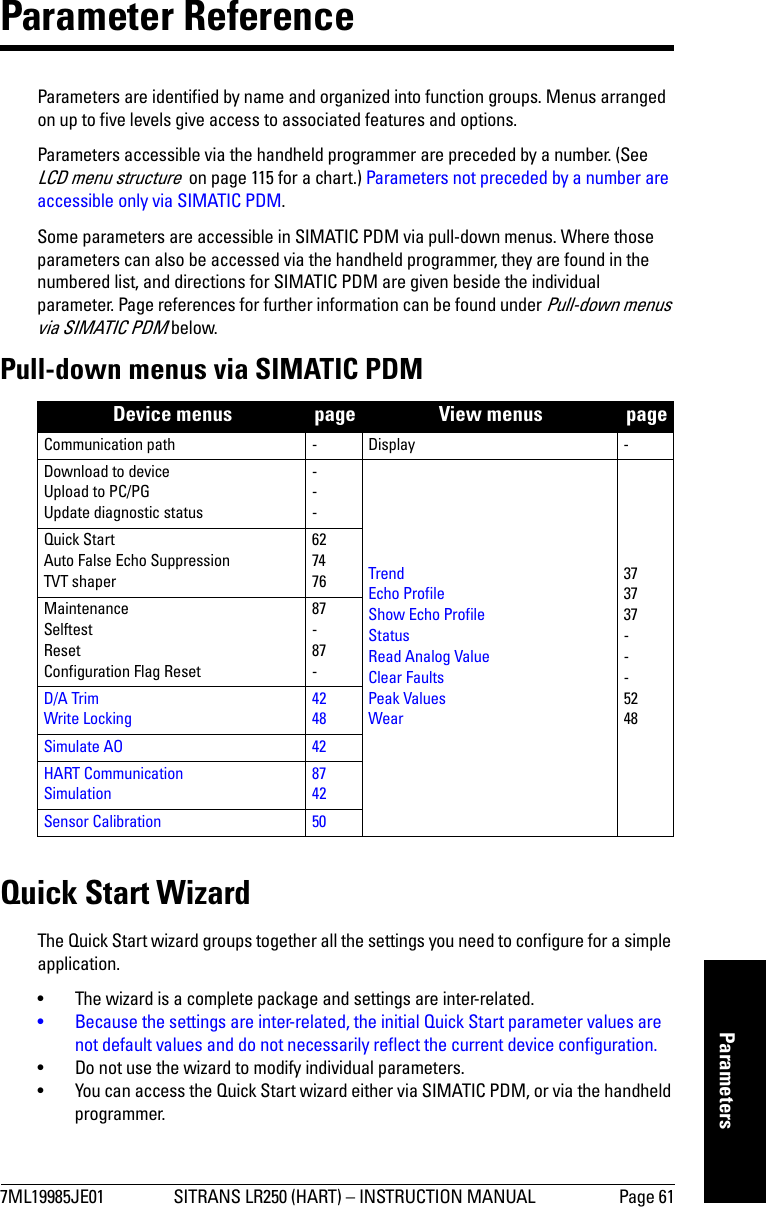
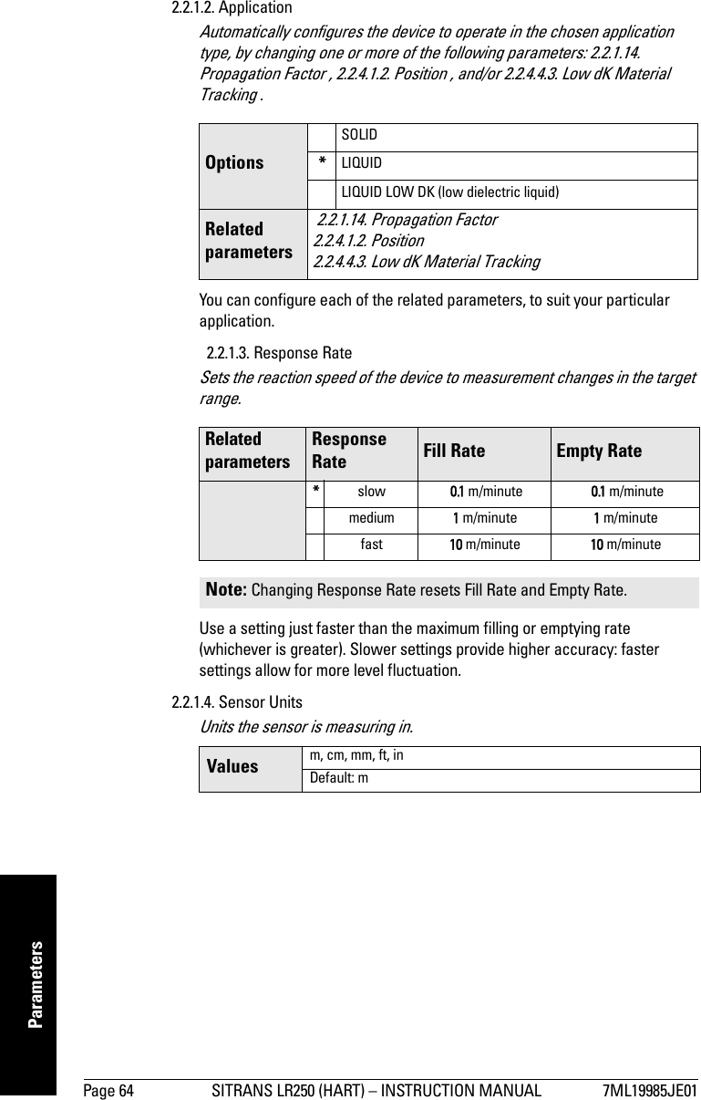
![Page 8 SITRANS LR250 (HART) – INSTRUCTION MANUAL 7ML19985JE01mmmmmSpecificationsFrequency 25.0 GHzMeasurement range10.3 to 20 m (1 to 65 ft)Update time at 4 mA 1 secondUpdate time digital ≤ 1.5 secondsBlanking distance242 mm (1.65") from end of hornInfluence of ambient temperature < 0.006% / K (average over full temperature range, referenced to maximum range)Dielectric constant• 1.5" and 2" horns εr >3• 3" and 4" horns εr > 2Memory:• non-volatile EEPROM• no battery required.Interface• HART standard, integral to analog output• configuration Siemens SIMATIC PDM (PC), or HART handheld communicator, or Siemens Milltronics infrared hand-held programmer• analog output 4 to 20 mA ± 0.02 mA accuracy (for detail, see non-linearity under Analog Output Accuracy on page 7)• display (local)3dot matrix with bar graph (representing level)MechanicalProcess Connections: • threaded connection 1.5” or 2" NPT, BSP, or G [BS EN ISO 228-1] • flange connection 2", 3", 4" (ANSI 150, 300#), 50, 80, 100 mm (PN16, 40, JIS 10K)• materials 316 L stainless steel, optional Hastelloy C22Antenna:• horn standard 1.5" (40mm) , 2" (48 mm), 3" (75 mm), and 4" (95 mm) horn, optional 100 mm (4") horn extension• materials 316L stainless steel with PTFE emitteroptional Hastelloy C22 with PTFE emitter1. Minimum range is horn length + 50 mm. For the reference point for each configuration, see SITRANS LR250 Dimensions on page 192. See Near Range (Blanking) on page 108 for more details.3. Display quality will be degraded in temperatures below –25 °C (–13 °F) and above +65 °C (+149 °F).](https://usermanual.wiki/Siemens-Canada-Siemens-Milltronics-Process-Instruments/LR250.USERS-MANUAL/User-Guide-748474-Page-12.png)
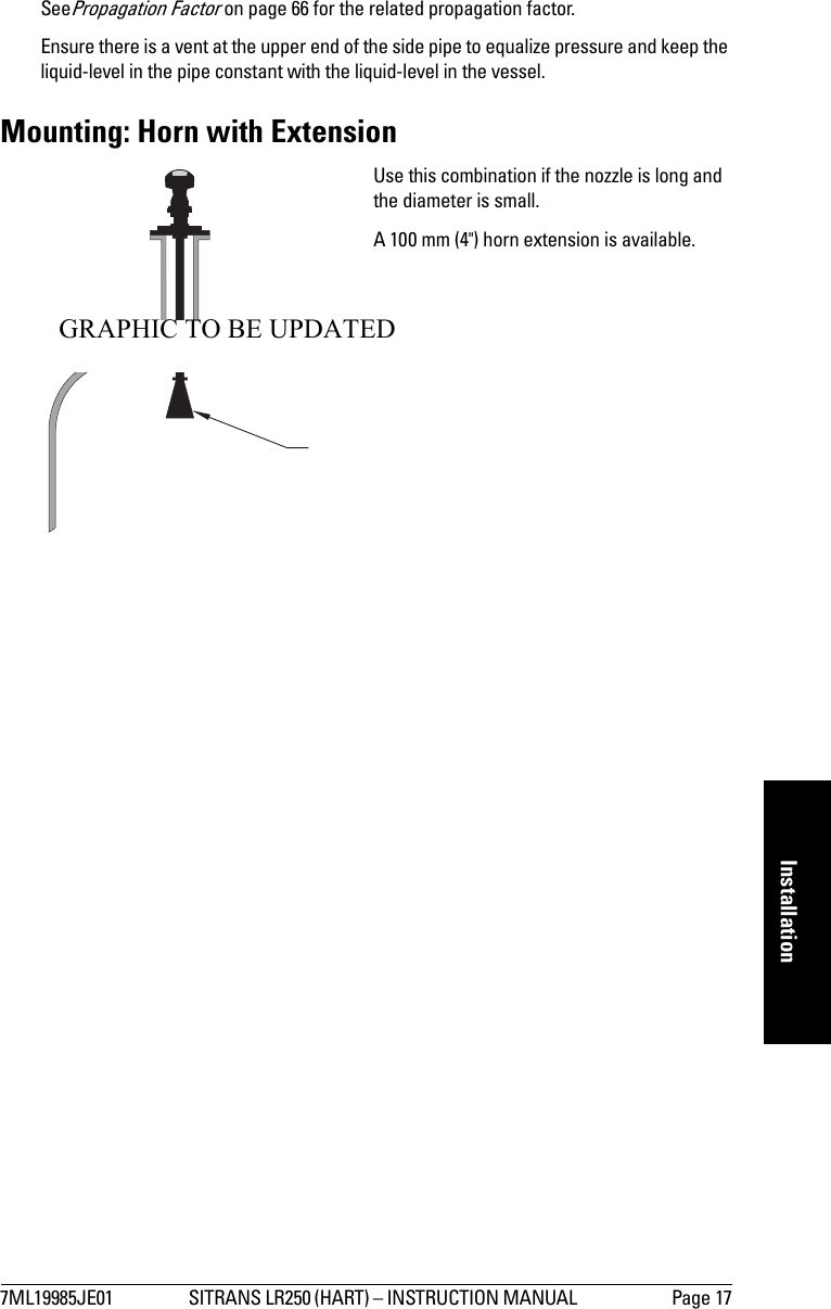
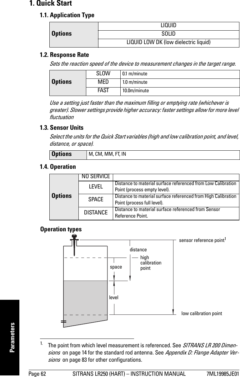
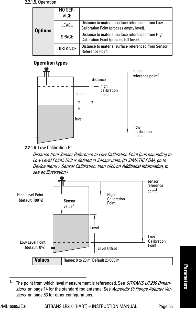
![Page 16 SITRANS LR250 (HART) – INSTRUCTION MANUAL 7ML19985JE01mmmmmInstallationHorn Location on NozzlesMounting: Stillpipe or Bypass (Sidepipe)This mounting arrangement is an alternative to the waveguide antenna option. It is used for products with an εr less than 3 or for extremely turbulent or vortex conditions. It can also be used to provide optimum signal conditions on foaming materials.Pipe requirementsDiameterSuitable pipe diameters are 50 mm (2”) to 100 mm (4”). SmoothnessOne continuous length of metallic pipe is preferred, without joints. If joints are unavoidable, you must machine them to close tolerances (± 0.25 mm [± 0.010”]) and weld a connecting sleeve on the outside.10 mm (0.4")GRAPHIC TO BE UPDATEDThe end of the horn should protrude aminimum of 10 mm (0.4”) to avoid inter-ference with the nozzleoptimum diameter80 mm (3”) align display window with ventsalign display window with stillpipe slotsMounting on a bypassMounting on a stillpipeGRAPHIC TO BE UPDATED](https://usermanual.wiki/Siemens-Canada-Siemens-Milltronics-Process-Instruments/LR250.USERS-MANUAL/User-Guide-748474-Page-20.png)
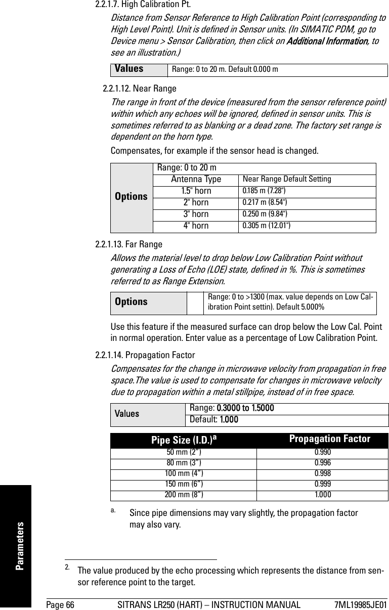
![7ML19985JE01 SITRANS LR250 (HART) – INSTRUCTION MANUAL Page 33mmmmmQuick StartQuick StartA Quick Start wizard groups together all the settings you need for a simple application. There are two ways to access the wizard:•Quick Start Wizard via the handheld programmer on page 35•Quick Start Wizard via SIMATIC PDM on page 38Activating SITRANS LR250Power up the instrument. SITRANS LR250 automatically starts up in Measurement (RUN) mode. Measurement mode (RUN mode) 1If more than one fault is present, the status indicator and text for each fault alternate at 2 second intervals. See General Fault Codes on page 79 for a list.Note: SITRANS LR250 supports SIMATIC PDM version 6.0 with SP2.Note: Keep infrared devices such as laptops, cell phones, and PDAs, away from SITRANS LR250 to prevent inadvertent operation.1. In response to a key press request. For details, see Navigating in PROGRAM mode on page 73.LEVEL[M]21.40 °CDATA EXCH.18.91134265Normal operation781 – toggle indicator for linear units or %2 – selected operation: level, space, or distance3 – measured value (level, space or distance)4 – units5 – bar graph indicates level6 – secondary region indicates electronics temperature, echo confidence, loop current, or distance17 – text area displays status messages 8 – device status indicatorS: 0 LOE S: 53 CONFIG LOFault present](https://usermanual.wiki/Siemens-Canada-Siemens-Milltronics-Process-Instruments/LR250.USERS-MANUAL/User-Guide-748474-Page-37.png)
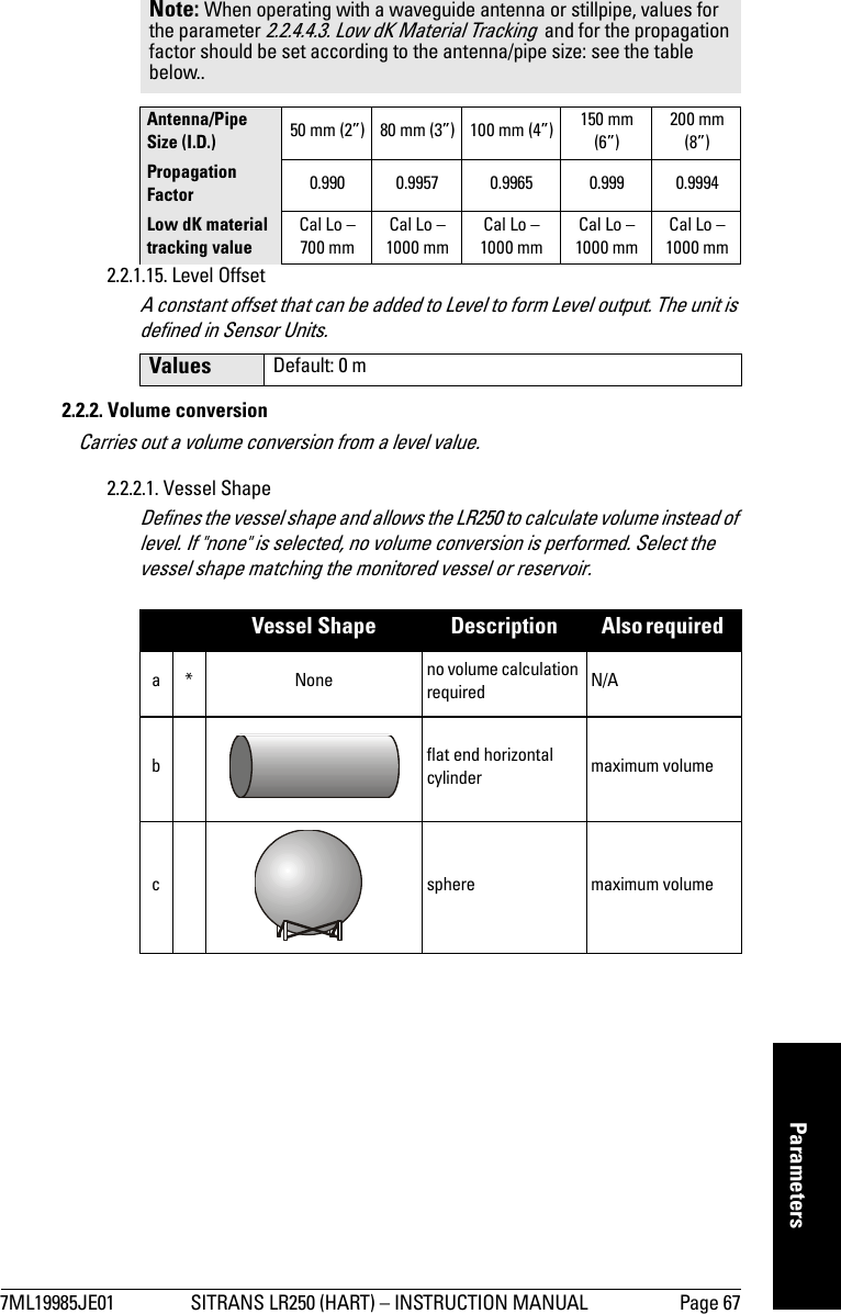
![Page 34 SITRANS LR250 (HART) – INSTRUCTION MANUAL 7ML1998JE01mmmmmQuick StartProgramming SITRANS LR250• For detailed information see Appendix F: Local Operation Interface on page 94. or Parameter Reference on page 41.• To program SITRANS LR250 using the Quick Start wizard, follow the instructions below.The handheld programmer and PROGRAM mode display• Point the programmer at the display (from a maximum distance of 600 mm [2 ft.]), then press Right ARROW to activate PROGRAM mode and open menu level 1. (Mode opens the menu level last displayed in PROGRAM mode within the last 10 minutes, unless power has been cycled since then. Then menu level 1 will be displayed.)•Use ARROW keys to navigate to a menu item. The current selection is highlighted and the level number is shown. A pointer is visible if a lower level exists.• Press Down or Up ARROWS to scroll to the next selection.• At higher menu levels press Right ARROW to open the next menu level or Left ARROW to back up one level.• At the lowest menu level, parameters are listed, and no pointers are visible. Press Right ARROW to open parameter view.• In parameter view, the parameter name and number are displayed, as well as current selection or value. Press Right ARROW to open Edit mode. Notes: • See Appendix F: Local Operation Interface on page 94 for more detailed information on the programmer and the LCD display.• SITRANS LR250 automatically returns to Measurement mode after a period of inactivity in PROGRAM mode (between 15 seconds and two minutes, depending on the menu level). INPUT 2.2.1SENSOR CALIBVOL CONVERSIONVOLUME BREAKPTECHO PROC.SENSOR CALIBAPPLICATIO..2.2.1.2LIQUIDPREVIOUSNEXTBACK EDIThandheld programmer (ordered separately)Max. 600 mm (2 ft)displaymenu pointerparameter numberparameter selectionunlocked iconGRAPHIC TOBE REVISEDcurrent item numbercurrent itemparameter name](https://usermanual.wiki/Siemens-Canada-Siemens-Milltronics-Process-Instruments/LR250.USERS-MANUAL/User-Guide-748474-Page-38.png)
![7ML19985JE01 SITRANS LR250 (HART) – INSTRUCTION MANUAL Page 35mmmmmQuick Start• The current selection is highlighted. If required, scroll to a new selection or key in a new value and press Right ARROW to accept it. The LCD displays the new value.• Press Mode to return to Measurement mode.Quick Start Wizard via the handheld programmer1. Quick Starta. Point the programmer at the display (from a maximum distance of 600 mm [2 ft.]), then press Right ARROW to activate PROGRAM mode and open menu level 1. b. Press Right ARROW twice to navigate to menu item 1.1 and open parameter view. c. Press Right ARROW to open Edit mode or Down ARROW to accept default values and move directly to the next item.d. To change a setting, scroll to the desired item or key in a new value.e. After modifying a value, press Right ARROW to accept it and press Down ARROW to move to the next item. f. Quick Start settings take effect only after you select Yes to Apply changes in step 1.7.1.1. Application Type1.2. Response RateSets the reaction speed of the device to measurement changes in the target range.Use a setting just faster than the maximum filling or emptying rate (whichever is greater). Slower settings provide higher accuracy: faster settings allow for more level fluctuationNotes: • The wizard is a complete package and the settings are inter-related.• Because the settings are inter-related, the initial Quick Start parameter values are not default values and do not necessarily reflect the current device configuration.• Do not use the Quick Start wizard to modify individual parameters: see instead Parameter Reference on page 41.OptionsLIQUIDSOLIDLIQUID LOW DK (low dielectric liquid) OptionsSLOW 0.1 m/minuteMED 1.0 m/minuteFAST 10.0m/minuteAPPLICATIO..2.2.1.2SOLIDLIQUID LOW DKLIQUID](https://usermanual.wiki/Siemens-Canada-Siemens-Milltronics-Process-Instruments/LR250.USERS-MANUAL/User-Guide-748474-Page-39.png)
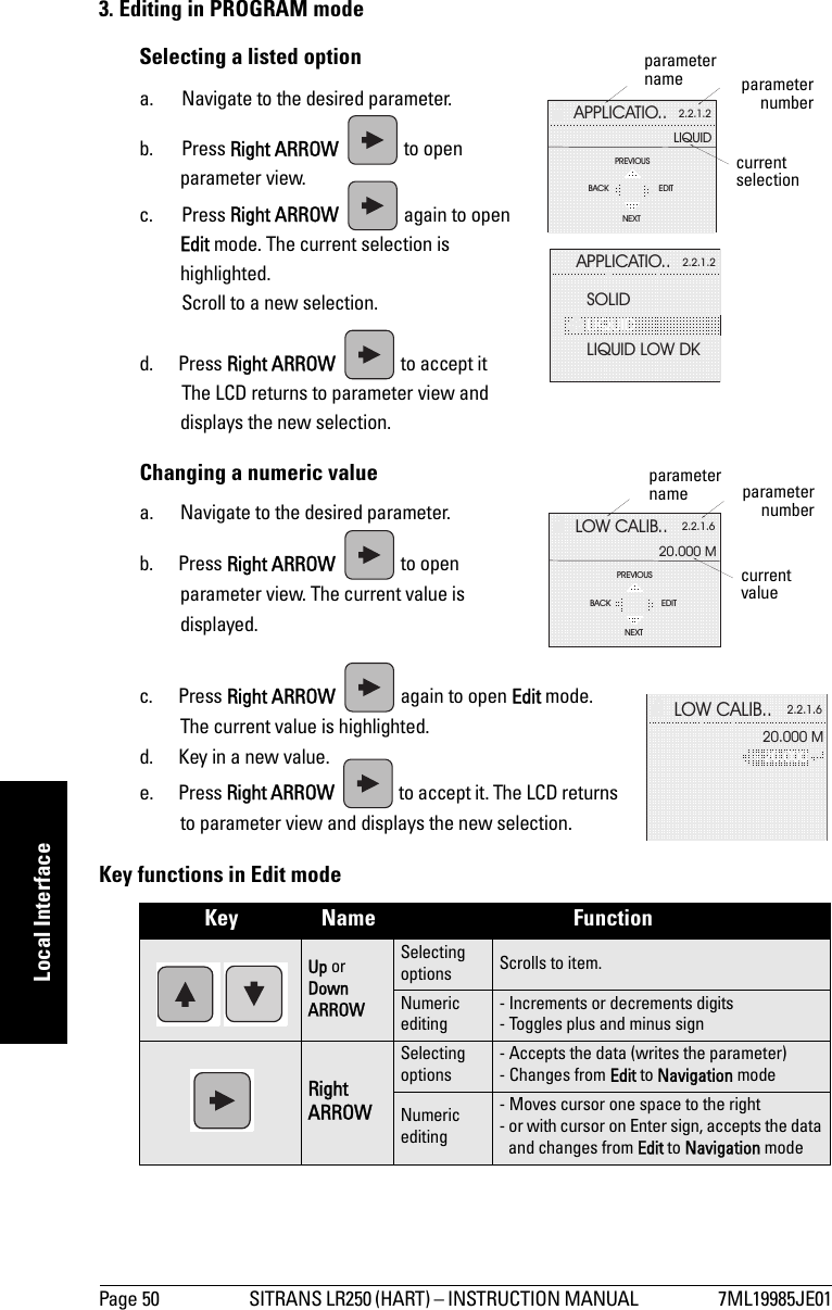
![Page 46 SITRANS LR250 (HART) – INSTRUCTION MANUAL 7ML19985JE01mmmmmLocal InterfaceLocal Operation Interface• The handheld programmer allows you to change parameter values and set operating conditions to suit your specific application. • View settings on the LCD display, or request an echo profile, in PROGRAM mode. • View the measured value and additional status information, on the LCD display in Measurement mode (RUN mode).Parameter accessParameters are identified by name and organized into function groups, then arranged in a hierarchical menu structure (see LCD menu structure on page 115). For example: The LCD DisplayMeasurement mode (RUN mode)Normal operationIf more than one fault is present, the status indicator and text for each fault alternate at 2 second intervals. See General Fault Codes on page 79 for a list.Note: The complete range of parameters is only accessible via PDM. See Parameter Reference on page 47 for a complete list with instructions.2. SETUP2.2. INPUT2.2.1 SENSOR CALIB2.2.1.13. RESPONSE RATELEVEL[M]21.40 °CDATA EXCH.18.91134265781 – measured value (level, space or distance)2 – toggle indicator for linear values or %3 – level, distance, or space4 – units5 – bar graph indicates level6 – secondary region indicates electronics temperature, echo confidence, loop current, or distance in response to a key press. (See Key functions in Measurement mode on page 47).7 – text area displays status messages8 – device status indicatorS: 0 LOE S: 53 CONFIG LOFault present](https://usermanual.wiki/Siemens-Canada-Siemens-Milltronics-Process-Instruments/LR250.USERS-MANUAL/User-Guide-748474-Page-50.png)
![7ML19985JE01 SITRANS LR250 (HART) – INSTRUCTION MANUAL Page 49mmmmmLocal InterfaceProgramming via the handheld programmerThe handheld programmer allows you to change parameter values and set operating conditions to suit your specific application.• For the complete list of parameters with instructions, see Parameter Reference on page 47.•See LCD menu structure on page 115 for a chart.1. Enter PROGRAM mode• Point the programmer at the display (from a maximum distance of 600 mm [2 ft.]).•Right ARROW activates PROGRAM mode and opens menu level 1. •Mode opens the menu level last displayed in PROGRAM mode within the last 10 minutes, or menu level 1 if power has been cycled since then.2. Navigating: key functions in Navigation modeNotes: • Do not use the Quick Start settings if you want to modify an individual parameter.• The Quick Start wizard groups the settings required for a simple application into one package and the settings are inter-related.• Because the settings are inter-related, the initial Quick Start parameter values are not default values and do not necessarily reflect the current device configuration.• SITRANS LR250 automatically returns to Measurement mode after a period of inactivity in PROGRAM mode (between 25 seconds and 10 minutes, depending on the menu level).Key Name Menu level Function Up or Down ARROW menu or parameter Scroll to previous or next menu or parameter.Right ARROW menu Go to first parameter in the selected menu, or open next menu.parameter Open Edit mode.Left ARROW menu or parameter Open parent menu.Mode menu or parameter Change to MEASUREMENT mode.Home menu or parameter Open top level menu at first item: menu 1, item 1.displayhandheld programmer (ordered separately)Max. 600 mm (2 ft)](https://usermanual.wiki/Siemens-Canada-Siemens-Milltronics-Process-Instruments/LR250.USERS-MANUAL/User-Guide-748474-Page-53.png)
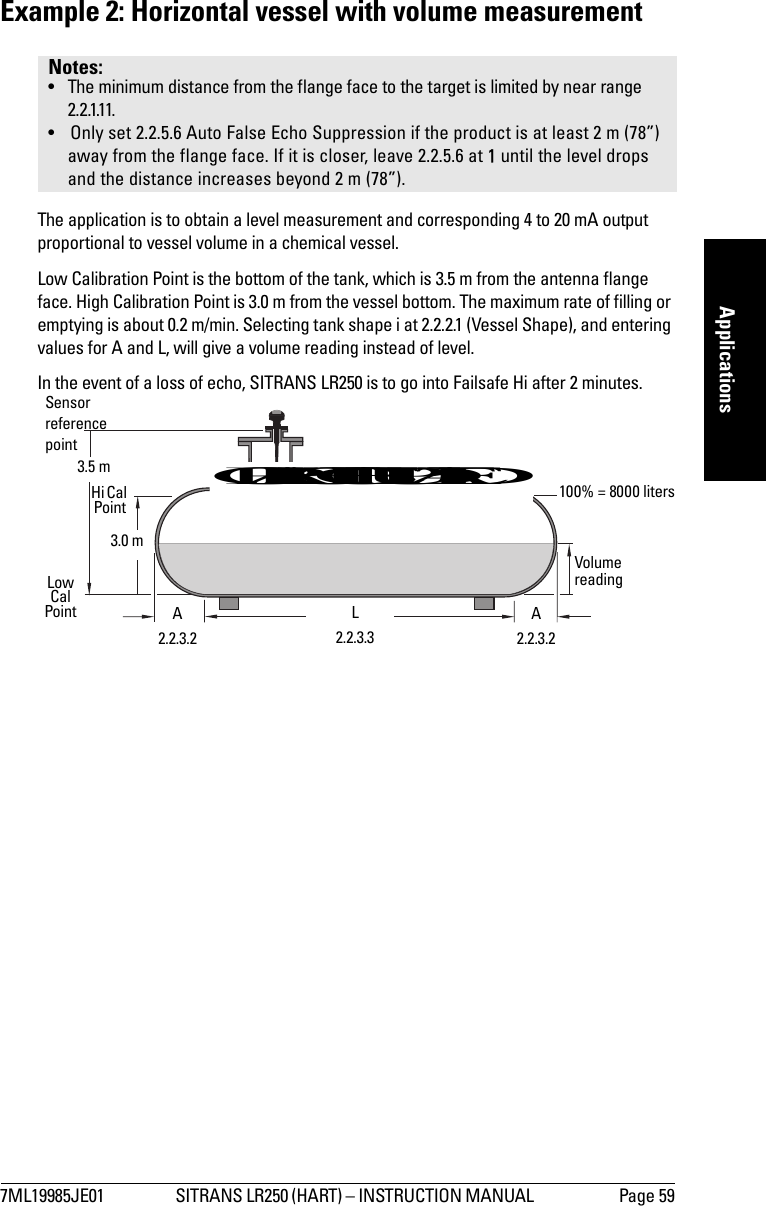
![Page 58 SITRANS LR250 (HART) – INSTRUCTION MANUAL 7ML19985JE01mmmmmApplicationsApplication ExamplesYou can use these examples as setup references. Enter the values in the parameter tables to select the corresponding functions.Example 1: Liquid resin in storage vessel, level measurementReturn to Measurement: press Mode to start normal operation.Notes: • The minimum distance from the flange face to the target is limited by near range 2.2.1.11.• Only set 2.2.5.6 (Auto False Echo Suppression) if the product is at least 2 m (78”) away from the flange face. If it is closer, leave 2.2.5.6 at 1 until the level drops and the distance increases beyond 2 m (78”).Parameter Description Value Function2.2.1.5 operation Level Level2.2.7.1 measurement response Med 1 m/minute2.2.1.4 units Mmeters2.2.1.6 low calibration point 55 m2.2.1.7 high calibration point 4.5 4.5 m2.4.1 Failsafe timer 22 minutes2.4.2 Failsafe Material Level HI Hi 2.2.5.7 Auto False-Echo Suppression Distance[Distance1 minus 0.42 m]1. Distance to product from reference point.Sets length of learned TVT curve2 to use2. For more details see Range (Auto Suppression Range) on page 75 and Auto False Echo Suppression on page 74. 2.2.5.6 Auto False-Echo Suppression 2 then 1Enables the use of learned TVT curve2.The application is to obtain a level measurement and corresponding 4 to 20 mA output proportional to resin levels in a storage vessel. Low Calibration Point is the bottom of the tank, which is 5 m from the antenna flange face. High Calibration Point is 4.5 m from the vessel bottom. The maximum rate of filling or emptying is about 0.2 m/min. In the event of a loss of echo, SITRANS LR250 is to go into Failsafe Hi after 2 minutes.4.5 m Low Cal Point5 m 100% Level0% LevelHighCalPointSensorreferencepointGRAPHIC TO BE UPDATED](https://usermanual.wiki/Siemens-Canada-Siemens-Milltronics-Process-Instruments/LR250.USERS-MANUAL/User-Guide-748474-Page-62.png)
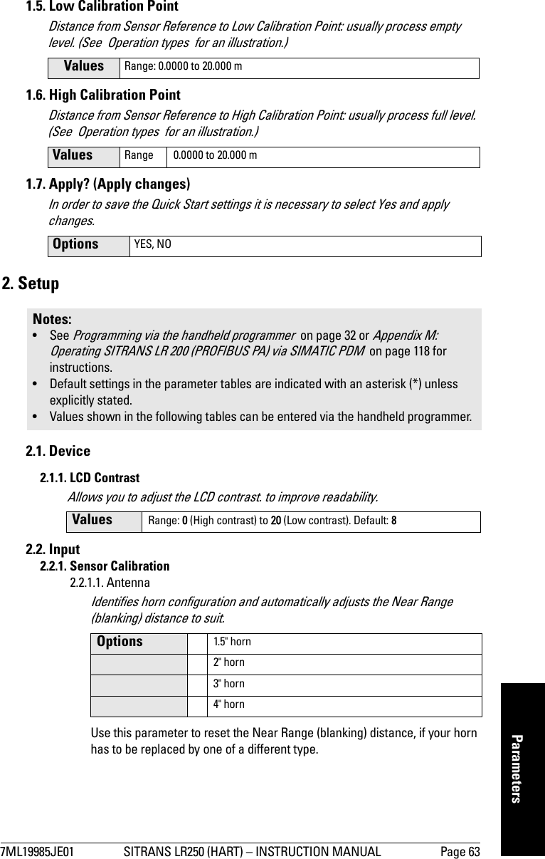
![Page 60 SITRANS LR250 (HART) – INSTRUCTION MANUAL 7ML19985JE01mmmmmApplicationsReturn to Measurement: press Mode to start normal operation.Parameter Description Values Function2.2.1.5 operation Level Volume replaces Level when a tank shape is selected at 2.2.2.12.2.7.1 measurement response Med 1 m/minute2.2.1.4 units Mmeters2.2.1.6 low calibration point 3.5 3.5 m2.2.1.7 high calibration point 33 m2.2.2.1 vessel shape iparabolic ends2.2.3.1 maximum volume 8000 8000 liters2.2.3.2 vessel dimension A .8 0.8 meters2.2.3.3 vessel dimension L 66 meters2.4.1 Failsafe timer 22 minutes2.4.2 Failsafe HI Hi 2.2.5.7Auto False-Echo Suppression Range[Distance1 minus 0.42 m]1. Distance to product from reference point.Sets length of learned TVT curve2 to use2. For more details see Range (Auto Suppression Range) on page 75 and Auto False Echo Suppression on page 74. For an explanation, see Auto False-Echo Suppression on page 108.2.2.5.6 Auto False-Echo Suppression 2 then1Enables the use of learned TVT curve2.](https://usermanual.wiki/Siemens-Canada-Siemens-Milltronics-Process-Instruments/LR250.USERS-MANUAL/User-Guide-748474-Page-64.png)


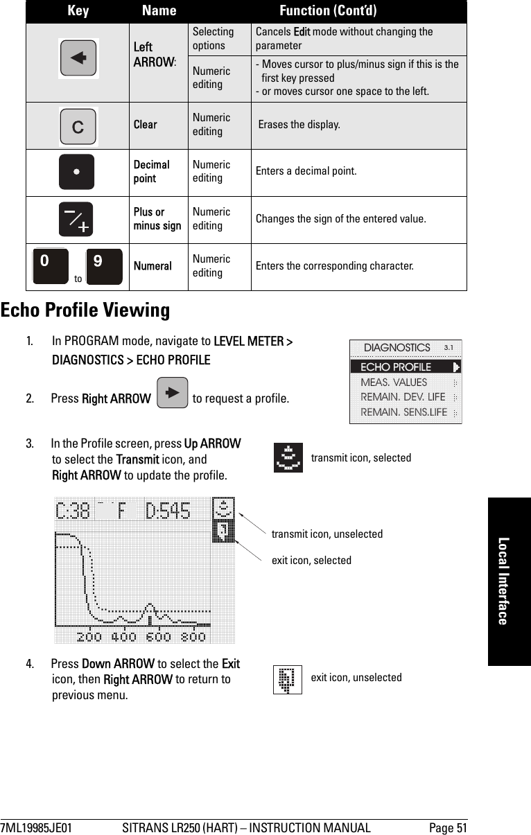
![7ML19985JE01 SITRANS LR250 (HART) – INSTRUCTION MANUAL Page 97mmmmmC: TroubleshootingAppendix C: TroubleshootingCommunication TroubleshootingGenerally:1. Check the following:• There is power at the instrument• The LCD shows the relevant data• The device can be programmed using the hand programmer2. Verify that the wiring connections are correct.3. If you continue to experience problems, go to our website at: . www.siemens.com/processautomation, and check the FAQs for SITRANS LR250, or contact your local Siemens Milltronics representative.Specifically:1. If you try to set a SITRANS LR250 parameter via remote communications, but the parameter remains unchanged:• Some parameters can only be changed when the device is not scanning. Try putting the device in PROGRAM mode using the operating mode function.• Try setting the parameter from the keypad. (First make sure that the lock parameter [6.1] is set to the unlock value.)• The communications control parameter 5.2 must be set to 1 to allow you to write parameters to SITRANS LR250.2. If you see unanticipated displays, for example:• PROGRAM mode displayed instead of Measurement mode• the wrong parameter displayed in response to a command• a parameter displayed in response to no commandmake sure no infrared-capable device is close to SITRANS LR250. Any device with infrared capabilities (laptops, cell phones, PDAs) can cause interference which simulates a command to the SITRANS LR250, potentially causing it to switch modes or to change a parameter.3. If the operation is erratic, make sure the Hand Programmer is not being used at the same time as SIMATIC PDM.](https://usermanual.wiki/Siemens-Canada-Siemens-Milltronics-Process-Instruments/LR250.USERS-MANUAL/User-Guide-748474-Page-101.png)