Siemens Canada Siemens Milltronics Process Instruments LR250 SITRANS LR 250 TANK LEVEL PROBING RADAR User Manual SITRANS LR250 FOUNDATION FIELDBUS
Siemens Canada Ltd. - Siemens Milltronics Process Instruments SITRANS LR 250 TANK LEVEL PROBING RADAR SITRANS LR250 FOUNDATION FIELDBUS
Contents
User Manual 4
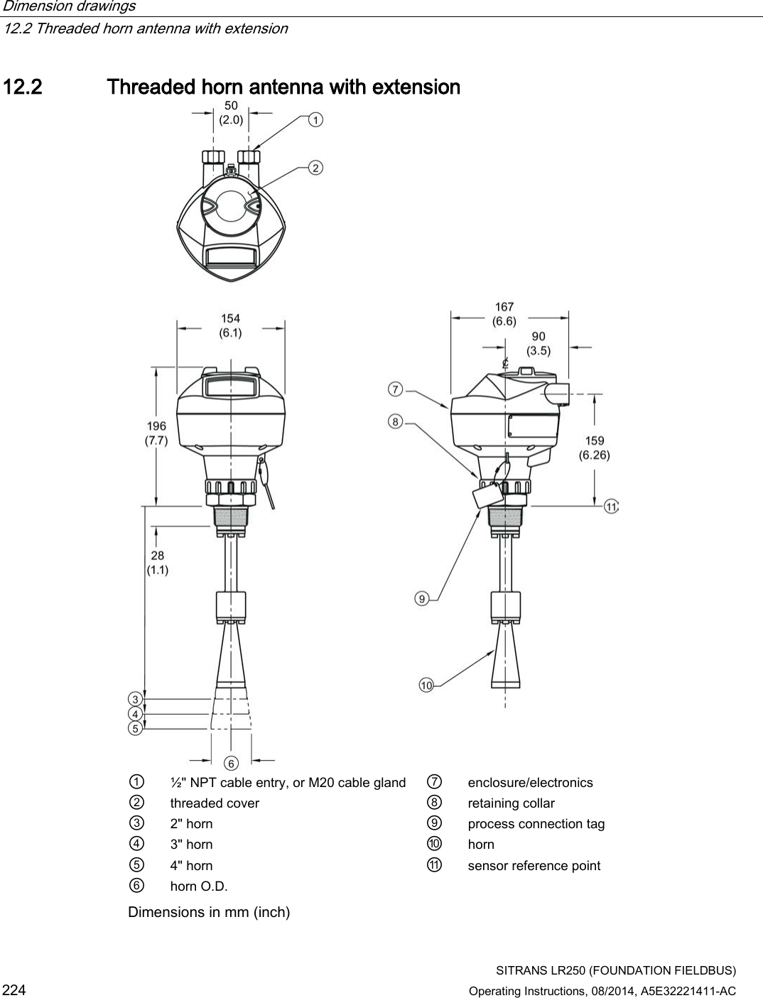
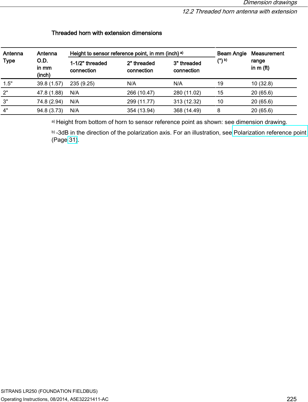
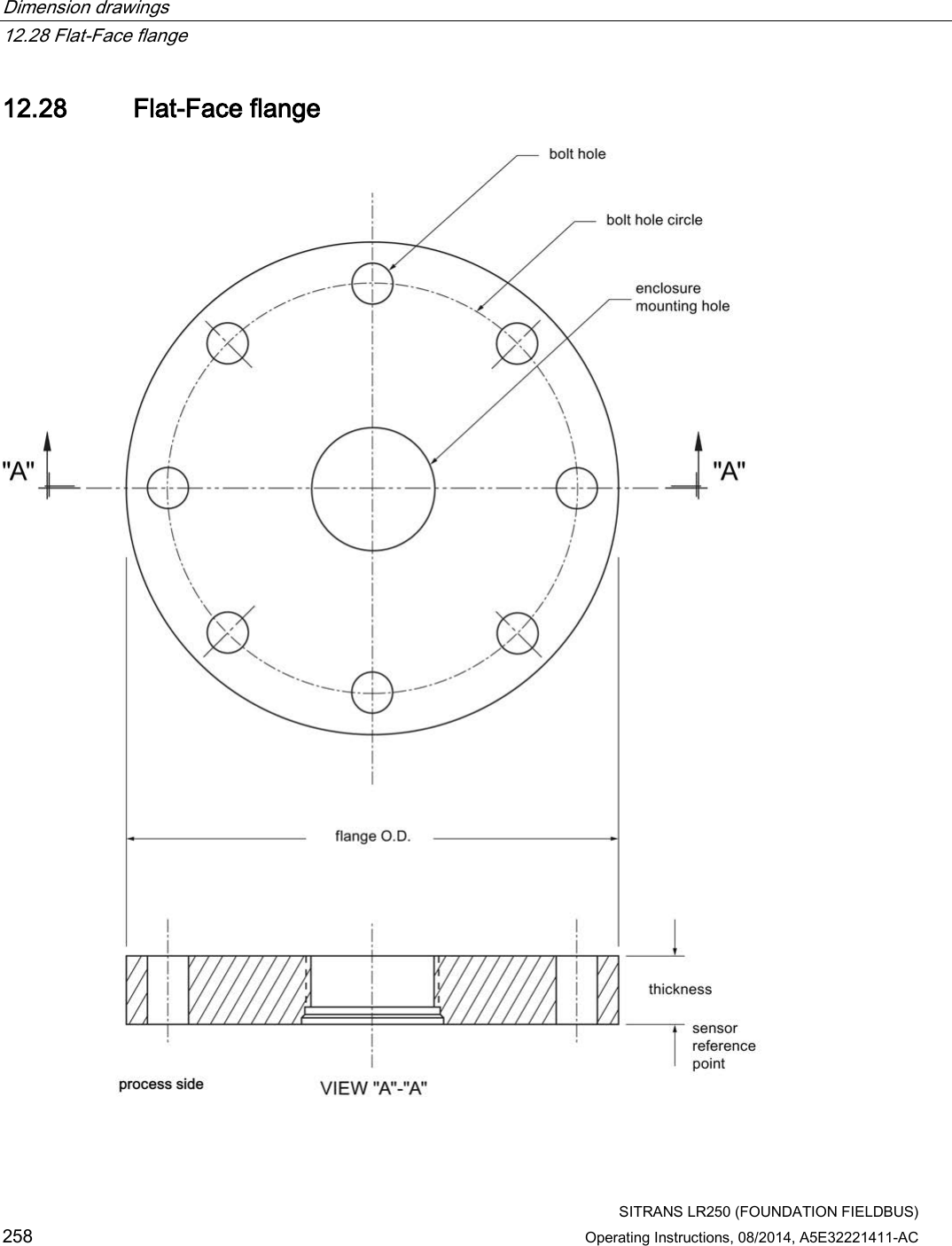
![Parameter reference 7.1 Operating via AMS Device Manager SITRANS LR250 (FOUNDATION FIELDBUS) Operating Instructions, 08/2014, A5E32221411-AC 147 LOE Timer (2.3.6.) Note See Loss of Echo (LOE) (Page 274) for more detail. Sets the time to elapse since the last valid reading, before the Fail-safe material level is reported. Values Range: 0 to 7200 seconds Default: 100 s Calibration (2.3.7) Low Calibration Pt. (2.3.7.1.) Distance from sensor reference point to Low Calibration Point (corresponding to Low Level Point). Units are defined in Unit (2.3.1.). ① High level point (default 100%) ⑥ Level offset (if used) ② Low level point (0%) ⑦ Low calibration point ③ Sensor value ⑧ Sensor reference point a) ④ High calibration point ⑨ Far range ⑤ Level a) The point from which level measurement is referenced [see Flat Faced Flange (Page 258) and Threaded Horn Antenna with extension (Page 221) and Flanged encapsulated antenna (3"/DN80/80A sizes and larger). (Page 232) ]. Values Range: 0.00 to 20.00 m. Default 20.00 m Related parameters Unit (2.3.1.) Far Range (2.5.2.)](https://usermanual.wiki/Siemens-Canada-Siemens-Milltronics-Process-Instruments/LR250.User-Manual-4/User-Guide-2277919-Page-5.png)
![Parameter reference 7.1 Operating via AMS Device Manager SITRANS LR250 (FOUNDATION FIELDBUS) 148 Operating Instructions, 08/2014, A5E32221411-AC High Calibration Point (2.3.7.2.) Distance from sensor reference point 1) to High Calibration Point (corresponding to High Level Point). Units are defined in Unit (2.3.1.). See Low Calibration Point (2.3.7.1.) for an illustration. Values Range: 0.00 to 20.00 m. Default 0.00 m Related parameters Unit (2.3.1.), Near Range (2.5.1.) When setting the High Calibration Point value, note that echoes are ignored within Near Range (2.5.1.). 1) The value produced by the echo processing which represents the distance from sensor reference point to the target. [see Threaded Horn Antenna with extension, (Page 224) Flanged Horn with extension (Page 228), and Flanged encapsulated antenna (3"/DN80/80A sizes and larger) (Page 232)]. Sensor Offset (2.3.7.3.) A constant offset that can be added to or subtracted from the sensor value to compensate for a shifted sensor reference point. (For example, when adding a thicker gasket or reducing the standoff/nozzle height.) The units are defined in Unit (2.3.1.). Values Range: -99.999 to 99.999 Default: 0.000 m Related Parameters Unit (2.3.1.) See How the LTB works: in manual Foundation Fieldbus for Level Instruments (7ML19985MP01) for more details on sensor offset. Low Level Point (2.3.7.4.) The level when the material is at Low Calibration Point. The unit is defined in Level Unit (2.3.2.). Values Range: -999999 to 999999 Default: 0% High Level Point (2.3.7.5.) The level when the material is at High Calibration Point. The unit is defined in Level Unit (2.3.2.). Values Range: -999999 to +999999 Default: 100%](https://usermanual.wiki/Siemens-Canada-Siemens-Milltronics-Process-Instruments/LR250.User-Manual-4/User-Guide-2277919-Page-6.png)
![Parameter reference 7.1 Operating via AMS Device Manager SITRANS LR250 (FOUNDATION FIELDBUS) Operating Instructions, 08/2014, A5E32221411-AC 149 Level Offset (2.3.7.6.) A constant offset that can be added to Level. The unit is defined in Level Unit (2.3.2.). Values Range: -999999 to +999999 Default: 0% Rate (2.3.8.) Response Rate (2.3.8.1.) Sets the reaction speed of the device to measurement changes. Note Changing Response Rate resets Fill Rate per Minute (2.3.8.2), Empty rate per Minute (2.3.8.3), and Shots (2.5.6.). Response Rate (2.3.8.1.) Fill Rate per Minute (2.3.8.2.)/ Empty rate per Minute (2.3.8.3.) Shots (2.5.6.) * Slow 0.1 m/min (0.32 ft/min) 25 Medium 1.0 m/min (3.28 ft/min) 10 Fast 10.0 m/min (32.8 ft/min) 5 Use a setting just faster than the maximum filling or emptying rate (whichever is faster). Fill Rate per Minute (2.3.8.2.) Defines the maximum rate at which the reported sensor value is allowed to decrease. Allows you to adjust the SITRANS LR250 response to decreases in the actual material level. Fill Rate is automatically updated whenever Response Rate (2.3.8.1.) is altered. Sensor value is the value produced by the echo processing which represents the distance from sensor reference point to the target [see Low Calibration Point (2.3.7.1.) for an illustration]. Options Range: 0 to 999999 m / min. Response Rate (2.3.8.1.) Fill Rate per Minute (2.3.8.2.) * Slow 0.1 m/min (0.32 ft/min) Medium 1.0 m/min (3.28 ft/min) Fast 10.0 m/min (32.8 ft/min) Altered by: Response Rate (2.3.8.1.) Related parameters Level Unit (2.3.2.) Enter a value slightly greater than the maximum vessel-filling rate, in units per minute.](https://usermanual.wiki/Siemens-Canada-Siemens-Milltronics-Process-Instruments/LR250.User-Manual-4/User-Guide-2277919-Page-7.png)
![Parameter reference 7.1 Operating via AMS Device Manager SITRANS LR250 (FOUNDATION FIELDBUS) 150 Operating Instructions, 08/2014, A5E32221411-AC Empty Rate per Minute (2.3.8.3) Defines the maximum rate at which the reported sensor value is allowed to increase. Adjusts the SITRANS LR250 response to increases in the actual material level. Empty Rate is automatically updated whenever Response Rate is altered. The sensor value is the value produced by the echo processing which represents the distance from sensor reference point to the target [see Low Calibration Point (2.3.7.1.) for an illustration]. Options Range: 0 to 99999 m / min. Response Rate (2.3.8.1.) Empty Rate * Slow 0.1 m/min (0.32 ft/min) Medium 1.0 m/min (3.28 ft/min) Fast 10.0 m/min (32.8 ft/min) Altered by: Response Rate (2.3.8.1) Related parameters Level Unit (2.3.2.) Enter a value slightly greater than the vessel’s maximum emptying rate, in units per minute. Linearization (2.4.) Volume (2.4.1.) Carries out a volume conversion from a level value.](https://usermanual.wiki/Siemens-Canada-Siemens-Milltronics-Process-Instruments/LR250.User-Manual-4/User-Guide-2277919-Page-8.png)
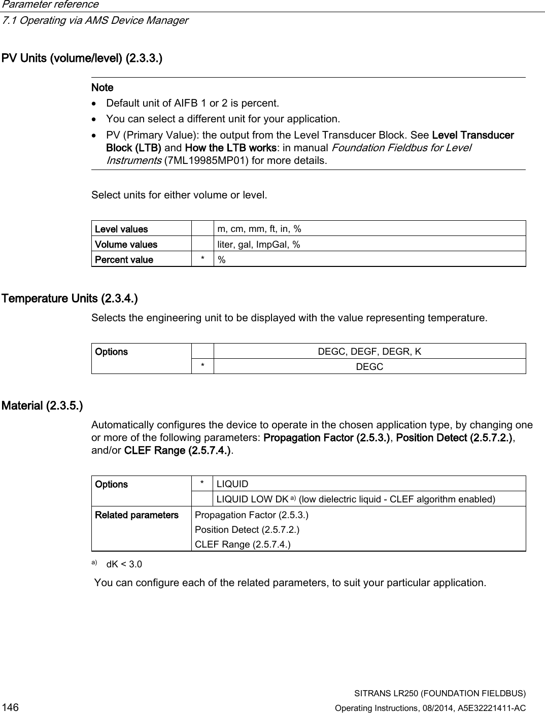
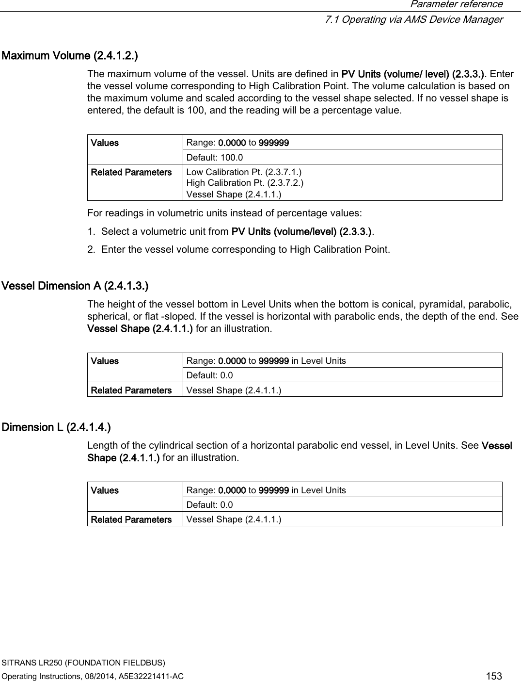
![Parameter reference 7.1 Operating via AMS Device Manager SITRANS LR250 (FOUNDATION FIELDBUS) 152 Operating Instructions, 08/2014, A5E32221411-AC Vessel Shape LCD DISPLAY/ Description Also required HALF SPHERE BOT/ Half-sphere bottom Maximum volume, dimension A FLAT SLOPED BOT/ Flat sloped bottom Maximum volume, dimension A PARABOLIC ENDS/ Parabolic end horizontal cylinder Maximum volume, dimension A, dimension L LINEAR TABLE a) / Linearization table (level/volume breakpoints) Maximum volume, level breakpoints, volume breakpoints a) Linearization Table must be selected in order for level/volume values [see XY index (2.4.1.5.)] to be transferred.](https://usermanual.wiki/Siemens-Canada-Siemens-Milltronics-Process-Instruments/LR250.User-Manual-4/User-Guide-2277919-Page-10.png)
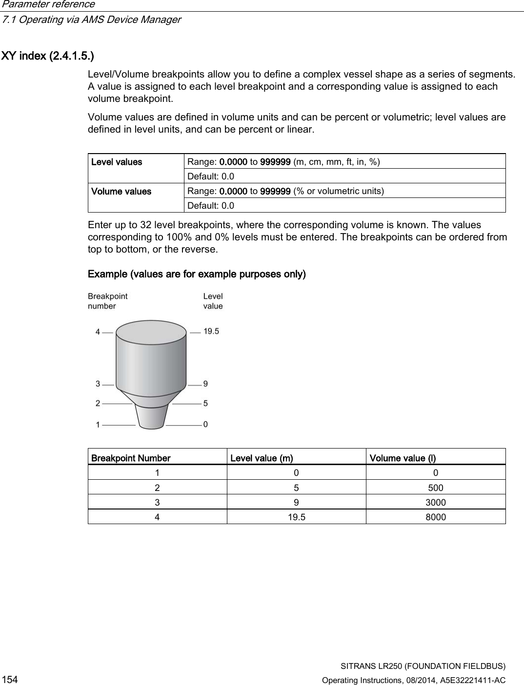
![Parameter reference 7.1 Operating via AMS Device Manager SITRANS LR250 (FOUNDATION FIELDBUS) Operating Instructions, 08/2014, A5E32221411-AC 155 Entering breakpoints via the hand-held programmer: 1. The default for level values is percent: if you want to select units instead, navigate to Setup (2.) > Sensor (2.3.) > Level Unit (2.3.2.), and select the desired unit. 2. Navigate to Setup (2.) > Sensor (2.3.) > PV Units (volume/level) (2.3.3.), and select the desired volume units. 3. Go to XY index (2.4.1.5.) and enter the number of the breakpoint you wish to adjust: for example, for breakpoint 1 enter 1. 4. Go to X value (2.4.1.6.) and enter the level value for the breakpoint just identified. 5. Go to Y value (2.4.1.7.) and enter the volume value for the breakpoint just identified. 6. Repeat steps 3 to 5 until values have been entered for all required breakpoints. X value (2.4.1.6.) See XY Index (2.4.1.5.). Y value (2.4.1.7.) See XY Index (2.4.1.5.). Entering breakpoints via AMS: See Linearization (LTB) (Page 97) After completing the above steps you will need to configure AIFB 1 and/or AIFB 2. [See AIFB 1 (2.6.) and AIFB 2 (2.7.) for details.] Signal Processing (2.5.) In AMS Device Manager, see the General tab under Signal Processing (LTB) (Page 99). Near Range (2.5.1.) The range in front of the device (measured from the sensor reference point within which any echoes will be ignored. (This is sometimes referred to as "Blanking" or "Dead Zone".) The factory setting is 50 mm (2") past the end of the antenna, and the range is dependent on the antenna type and process connection. [See Threaded Horn Antenna with extension (Page 221) and Flanged Horn (Page 226) for antenna heights to sensor reference point.] Values Range: 0 to 20 m (0 to 65.6 ft) Default depends on antenna type and process connection. Examples: 1.5" threaded horn 185.3 mm (7.3") 4" horn with stainless steel flange and 100 mm (4") extension 373.3 mm (14.7") Related parameters Unit (2.2.1.)](https://usermanual.wiki/Siemens-Canada-Siemens-Milltronics-Process-Instruments/LR250.User-Manual-4/User-Guide-2277919-Page-13.png)
![Parameter reference 7.1 Operating via AMS Device Manager SITRANS LR250 (FOUNDATION FIELDBUS) 158 Operating Instructions, 08/2014, A5E32221411-AC Minimum Sensor Value (2.5.4.) The minimum usable value for the measuring range, in units defined in Unit (2.3.1.). (Default = 0.0 m) To view this parameter via AMS Device Manager see Range under Signal Processing (LTB) (Page 99). Maximum Sensor Value (2.5.5.) The maximum usable value for the measuring range, in units defined in Unit (2.3.1.). (Default = 33.0 m) To view this parameter via AMS Device Manager see Range under Signal Processing (LTB) (Page 99). Shots (2.5.6.) The number of echo profile samples averaged to produce a measurement. Values Range: 1 to 25 Default: 25 a) a) To meet accuracy specification, the number of shots must be set to 25 [see Performance (Page 213)]. Echo Select (2.5.7.) Algorithm (2.5.7.1.) Selects the algorithm to be applied to the echo profile to extract the true echo. Options * tF True First echo F First echo L Largest echo BLF Best of Largest and First echo](https://usermanual.wiki/Siemens-Canada-Siemens-Milltronics-Process-Instruments/LR250.User-Manual-4/User-Guide-2277919-Page-16.png)
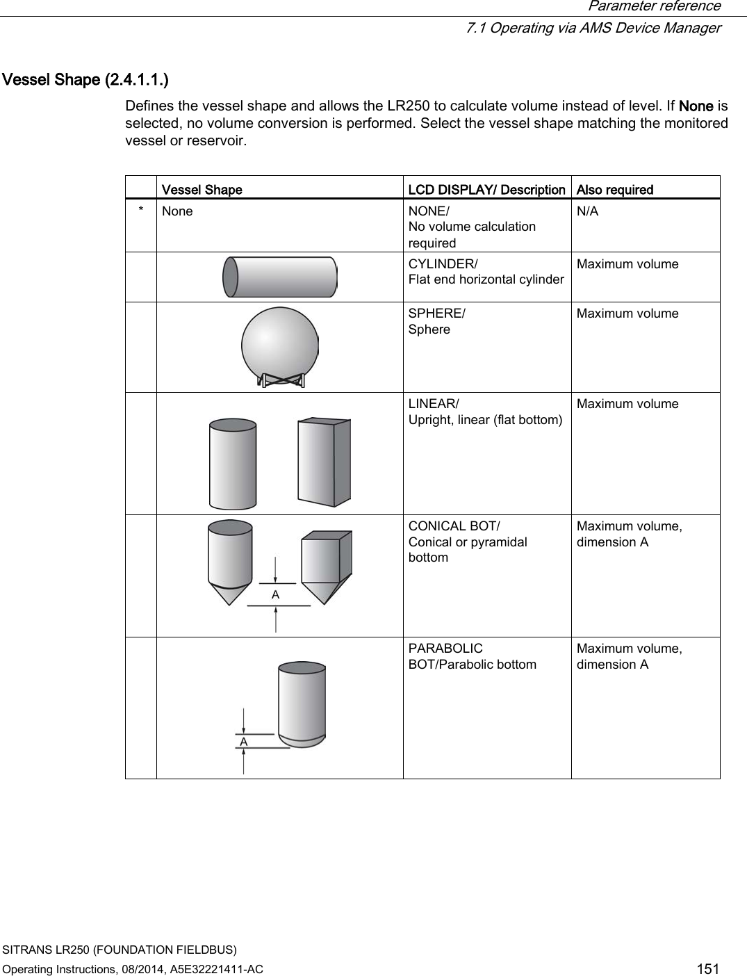
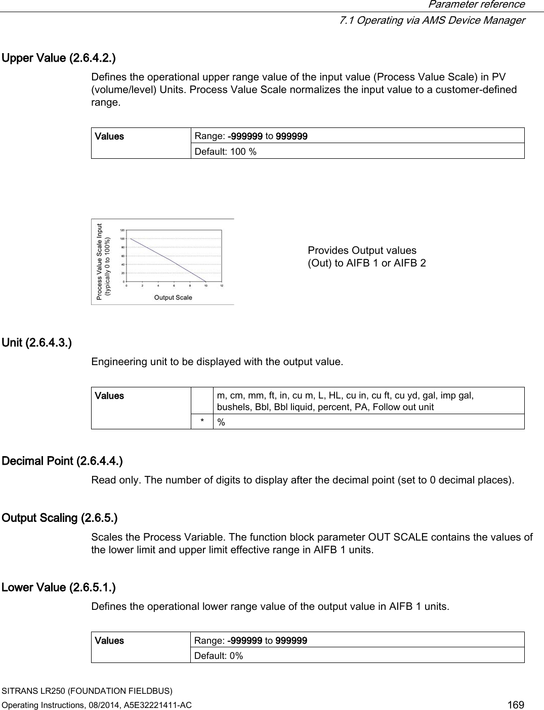
![Parameter reference 7.1 Operating via AMS Device Manager SITRANS LR250 (FOUNDATION FIELDBUS) 168 Operating Instructions, 08/2014, A5E32221411-AC Channel (2.6.3.) Used to select between the different Level Transducer Block outputs. Options Description Reference point LEVEL/VOLUME Level value converted to Volume [through Linearization (2.4.)] Low Calibration Point LEVEL * Level value Low Calibration Point DISTANCE Distance value Sensor Reference Point ① Distance ② High Calibration Point (process full level) ③ Sensor reference point a) ④ Low Calibration Point (process empty level) ⑤ Level a) The point from which High and Low Calibration points are referenced: see Dimension drawings (Page 221) and Threaded Horn Antenna with extension (Page 221). Input Scaling (2.6.4.) Lower Value (2.6.4.1.) Defines the operational lower range value of the input value (Process Value Scale) in PV (volume/level) Units. Process Value Scale normalizes the input value to a customer-defined range. Values Range: -999999 to 999999 Default: 0 %](https://usermanual.wiki/Siemens-Canada-Siemens-Milltronics-Process-Instruments/LR250.User-Manual-4/User-Guide-2277919-Page-26.png)
![Parameter reference 7.1 Operating via AMS Device Manager SITRANS LR250 (FOUNDATION FIELDBUS) Operating Instructions, 08/2014, A5E32221411-AC 171 Low Limit Warning (2.6.6.3.) The setting for the lower warning limit in AIFB1 units. Values Range: -Infinity to Infinity Default: -Inf Low Limit Alarm (2.6.6.4.) The setting for the lower alarm limit in AIFB1 units. Values Range: -Infinity to Infinity Default: -Inf Limit Hysteresis (2.6.6.5.) Hysteresis is used to adjust the sensitivity of the trigger for alarm messages. It is used to compensate when a process variable fluctuates around the same value as a limit. A high level alarm occurs when a value exceeds an upper limit. The alarm’s status remains true until the value drops below the limit minus the alarm hysteresis. The directions are reversed for low limit detection. Values Range: 0 to 50 Default: 0.50 Enter a value for the hysteresis here, to be used for all warnings and alarms. The units are the same as the Output scale, i.e. AIFB1 units. Display (2.6.7.) Filter Time Constant (2.6.7.1.) The time constant for the damping filter. The damping filter smooths out the response to a sudden change in level. This is an exponential filter and the engineering unit is always in seconds. See Damping (Page 273) for more detail. Values Range: 0 to 600 s Default: 0 a) a) To meet accuracy specification, Filter Time Constant (PV_FTIME) must be changed from default of 0.0 s to a minimum of 10.0 seconds [see Performance (Page 213)].](https://usermanual.wiki/Siemens-Canada-Siemens-Milltronics-Process-Instruments/LR250.User-Manual-4/User-Guide-2277919-Page-29.png)
![Parameter reference 7.1 Operating via AMS Device Manager SITRANS LR250 (FOUNDATION FIELDBUS) 172 Operating Instructions, 08/2014, A5E32221411-AC AIFB 2 (2.7.) See AIFB1 (2.6.): the parameters for AIFB 2 are identical to AIFB 1. Measured Values (2.8.) (for diagnostic purposes) Read only. Allows you to view measured values for diagnostic purposes. Main Output (PV - Primary Value) (2.8.1.) The value for level, or volume (if volume conversion is selected). In AMS Device Manager, see Process Variables Level Transducer Block-LTB (Page 128). Output, no linearization (SV1 - Secondary Value 1) (2.8.2.) The value for level. Output, no level offset (SV2 - Secondary Value 2) (2.8.3.) The value for distance. Diagnostics (3.) Echo Profile (3.1.) Allows you to request the current echo profile via the handheld programmer, or via AMS Device Manager. For more detail see Echo Processing (Page 266). To request a profile via AMS Device Manager: See Echo Profile (Page 103). To request a profile via the handheld programmer: 1. Navigate to Level Meter > Diagnostics (3.) > Echo Profile (3.1.). 2. Press RIGHT arrow to request a profile. [See Requesting an Echo Profile (Page 70) for more details.]](https://usermanual.wiki/Siemens-Canada-Siemens-Milltronics-Process-Instruments/LR250.User-Manual-4/User-Guide-2277919-Page-30.png)
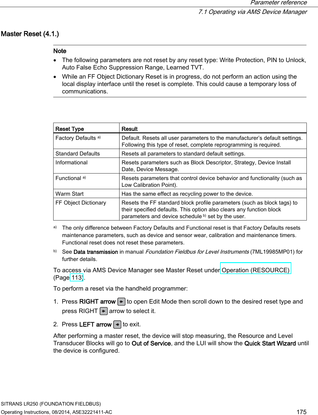
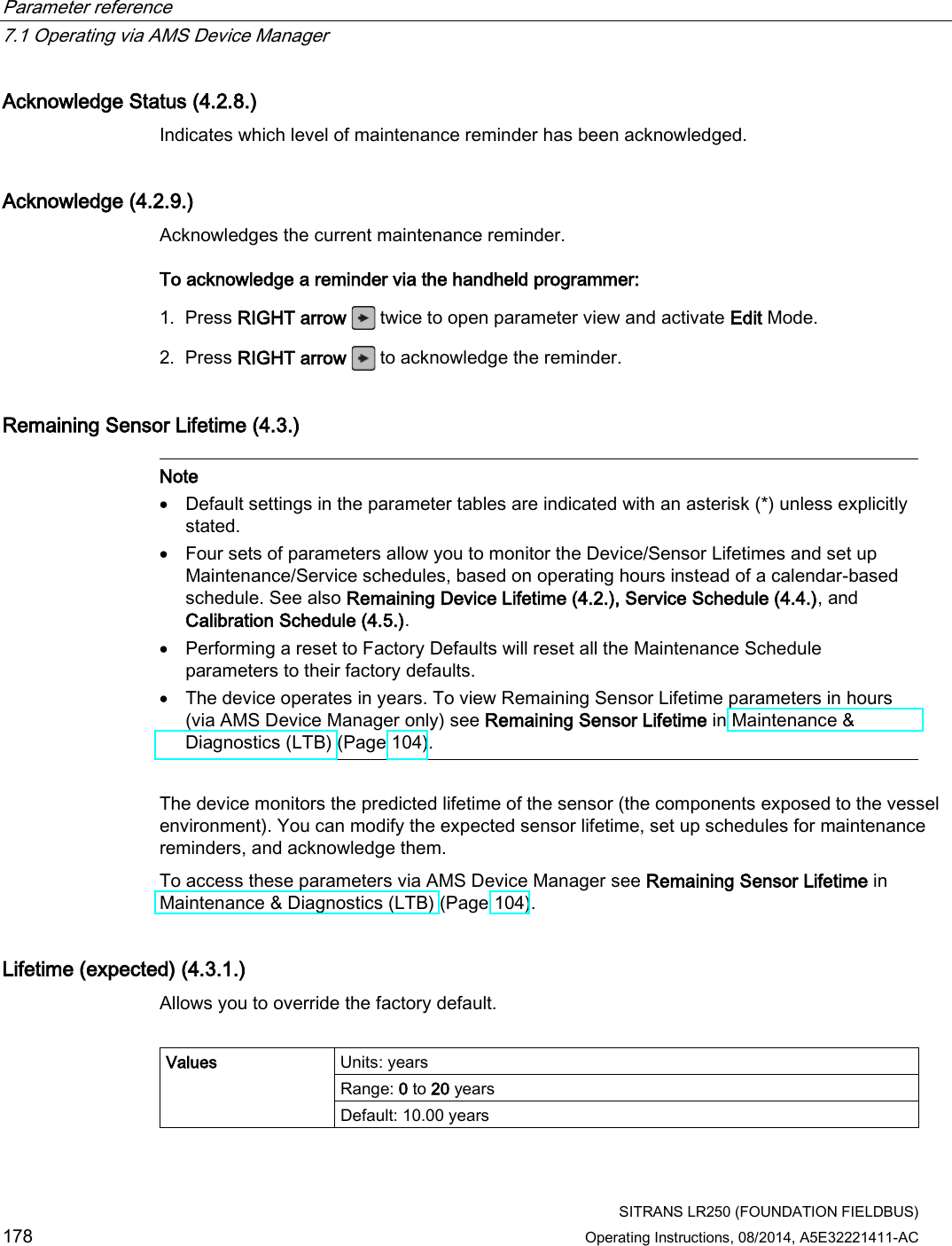
![Parameter reference 7.1 Operating via AMS Device Manager SITRANS LR250 (FOUNDATION FIELDBUS) Operating Instructions, 08/2014, A5E32221411-AC 177 Activation of Reminders (4.2.4.) Allows you to enable a maintenance reminder. Options REMinder 1 (Maintenance REQuired) REMinder 2 (Maintenance DEManded) REMinders 1 AND 2 (Maintenance Required and Maintenance Demanded) * OFF 1. First set the reminder values in Reminder 1 before Lifetime (Required) (4.2.5.)/Reminder 2 before Lifetime (Demanded) (4.2.6.). 2. Select the desired Activation of Reminders option. Reminder 1 before Lifetime (Required) (4.2.5.) If Remaining Lifetime (4.2.3.) is equal to or less than this value, the device generates a Maintenance Required reminder. Values Range: 0 to 20 years Default: 0.164 years 1. Modify limit values as required. 2. Set Activation of Reminders (4.2.4.) to the desired option. Reminder 2 before Lifetime (Demanded) (4.2.6.) If Remaining Lifetime (4.2.3.) is equal to or less than this value, the device generates a Maintenance Demanded reminder. Values Range: 0 to 20 years Default: 0.019 years 1. Modify values as required. 2. Set Activation of Reminders (4.2.4.) to the desired option. Maintenance Status (4.2.7.) Indicates which level of maintenance reminder is active. To display the level of maintenance reminder that is active in AMS Device Manager see Extended Diagnostics under Device Diagnostics [Resource Block - RESOURCE (Page 124)].](https://usermanual.wiki/Siemens-Canada-Siemens-Milltronics-Process-Instruments/LR250.User-Manual-4/User-Guide-2277919-Page-35.png)
![Parameter reference 7.1 Operating via AMS Device Manager SITRANS LR250 (FOUNDATION FIELDBUS) 186 Operating Instructions, 08/2014, A5E32221411-AC LCD Fast Mode (4.9.) Note • LCD Fast Mode takes effect only after 30 minutes of inactivity. (Each time the device is powered up, a further 30 minutes of inactivity is required.) • LCD Fast Mode affects Measurement mode only; it has no effect on Navigation mode. Enables a faster rate of measurement from the device by disabling most of the display area. Only the bar graph will be refreshed when LCD Fast Mode is set to ON. Values * OFF ON LCD Contrast (4.10.) The factory setting is for optimum visibility at room temperature and in average light conditions. Extremes of temperature will lessen the contrast. Values Range: 0 (High contrast) to 20 (Low contrast). Default: 10 Adjust the value to improve visibility at room temperature and in average light conditions. Change the value in small steps to ensure you can continue to read the display. Secondary Value (4.11.) Use the secondary value to capture the menu navigation path to any viewable parameter. Once the navigation path is stored, the value of that parameter will be displayed in Measurement mode as the secondary value. While in Parameter View of the current parameter [see Parameter View under LCD Display (Page 57)], press the decimal point key. This stores the path to the current parameter in the Secondary Value, and displays the value for that parameter on the LCD display when in Measurement mode. See The LCD Display (Page 57) for an illustration.](https://usermanual.wiki/Siemens-Canada-Siemens-Milltronics-Process-Instruments/LR250.User-Manual-4/User-Guide-2277919-Page-44.png)
![Parameter reference 7.1 Operating via AMS Device Manager SITRANS LR250 (FOUNDATION FIELDBUS) Operating Instructions, 08/2014, A5E32221411-AC 187 Simulate Enable (4.12.) Replaces a physical jumper switch found on some FF devices to enable simulation when set to ON. (Available only via LUI.) Options * OFF Simulation Disabled ON Simulation Enabled For more information on Simulation, see Simulation (Input) under Operation (LTB) (Page 93) in AMS Device Manager. [See also Simulation under How the AIFB works in manual Foundation Fieldbus for Level Instruments (7ML19985MP01)]. Communication (5.) Note Default settings in the parameter tables are indicated with an asterisk (*) unless explicitly stated. Tag (5.1.) Note The tag can only be changed from a remote master such as NIFBUS-Configurator or DeltaV. Read only. Text that can be used in any way. A recommended use is as a unique label for a field device in a plant. Limited to 32 ASCII characters. Device Address (5.2.) Note The address can only be changed from a remote master such as NIFBUS-Configurator or DeltaV. See Addressing in manual Foundation Fieldbus for Level Instruments (7ML19985MP01) for further details. Read only. The unique address of the device on the network. Values Temporary range during initial commissioning: 248 - 251. Permanent range after commissioning complete (written to non-volatile memory in the device): 16-247](https://usermanual.wiki/Siemens-Canada-Siemens-Milltronics-Process-Instruments/LR250.User-Manual-4/User-Guide-2277919-Page-45.png)
![Parameter reference 7.1 Operating via AMS Device Manager SITRANS LR250 (FOUNDATION FIELDBUS) Operating Instructions, 08/2014, A5E32221411-AC 189 Local Access (6.2.) Write Protection (6.2.1.) Note Do not lose this number value. Prevents any changes to parameters via AMS Device Manager or the handheld programmer. Hand-held programmer values Range: 0 to 9999 * Unlock value [stored in PIN to Unlock (6.2.2.)] Lock Off Any other value Lock On ● To turn Lock On, key in any value other than the Unlock Value stored in PIN to Unlock (6.2.2.). ● To turn Lock Off, key in the Unlock Value stored in PIN to Unlock (6.2.2.). To access this parameter via AMS Device Manager see Local Access under Security (RESOURCE) (Page 119). PIN to Unlock (6.2.2.) Note • Do not lose your Unlock Value: it cannot be displayed once Write Protection (6.2.1.) has been set to a different value. • A reset to Factory Defaults will not restore the unlock value at time of shipping. Stores the value to be entered in Write Protection (6.2.1.) to unlock programming. If Write Protection (6.2.1.) is set to a different value, PIN to Unlock (6.2.2.) does not display the Unlock value. Handheld Programmer Values Range: 0 to 9999 Value when shipped: 1954. Not restored by a reset to Factory Defaults. – – – – Display when Lock is on To access this parameter via AMS Device Manager see Local Access under Security (RESOURCE) (Page 119).](https://usermanual.wiki/Siemens-Canada-Siemens-Milltronics-Process-Instruments/LR250.User-Manual-4/User-Guide-2277919-Page-47.png)

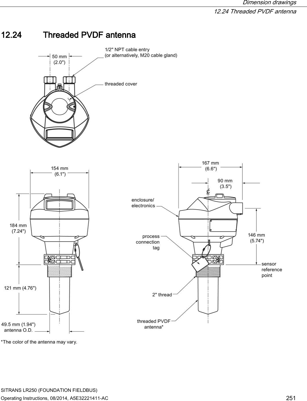
![Technical data 11.2 Performance SITRANS LR250 (FOUNDATION FIELDBUS) 214 Operating Instructions, 08/2014, A5E32221411-AC Measurement Accuracy (measured in accordance with IEC 60770-1) Maximum measured error =3 mm (0.12")1) 2) 3) including hysteresis and non-repeatability Frequency K-band Maximum measurement range4) 1.5" antenna 10 m (32.8 ft)5) 2" threaded PVDF antenna 2"/DN50/50A Flangedencapsulated antenna (FEA) 2" ISO 2852, DN50 DIN11864-1/2/3, DN50 DIN11851,Tuchenhagen Types F and N Hygienic encapsulated antenna (HEA) all other versions 20 m (65.6 ft) Minimum detectable distance 50 mm (2") from end of antenna6) Update time7) minimum 1 second, depending on settings for Response Rate (2.3.8.1.) and LCD Fast Mode (4.9.). Influence of ambient temperature < 0.003% / K (average over full temperature range, referenced to maximum range) Dielectric constant of material measured dK > 1.6 [antenna and application dependent8)] Memory non-volatile EEPROM no battery required 1) The statistical accuracy is typically 3 mm (0.12") 90% of the time, when tested in accordance with IEC 60770-1. 2) Under severe EMI/EMC environments per IEC 61326-1 or NAMUR NE21, the device error may increase to a maximum of 10 mm (0.4"). 3) For 2" threaded PVDF antenna, Flanged encapsulated antennas and Hygienic encapsulated antennas, the maximum measured error <500 mm from the sensor reference point =25 mm (1"). 4) From sensor reference point: see Dimension drawings (Page 221) and Flanged Horn with extension (Page 228). 5) 20 m (65.6 ft) possible in a stillpipe/bypass 6) Minimum range is antenna length +50 mm (2"). See Dimension drawings (Page 221). 7) Reference conditions: Response Rate (2.4.1.) set to FAST, LCD Fast Mode (4.9.) set to ON. 8) For 1.5" (40 mm) antenna and 2" (50 mm) threaded PVDF antenna, 2"/DN50/50A flanged encapsulated antenna and 2" ISO 2852, DN50 DIN 11864-1/2/3, DN50 DIN11851, Tuchenhagen Types F and N hygienic encapsulated antenna the minimum dK is limited to 3 unless a stillpipe is used.](https://usermanual.wiki/Siemens-Canada-Siemens-Milltronics-Process-Instruments/LR250.User-Manual-4/User-Guide-2277919-Page-72.png)
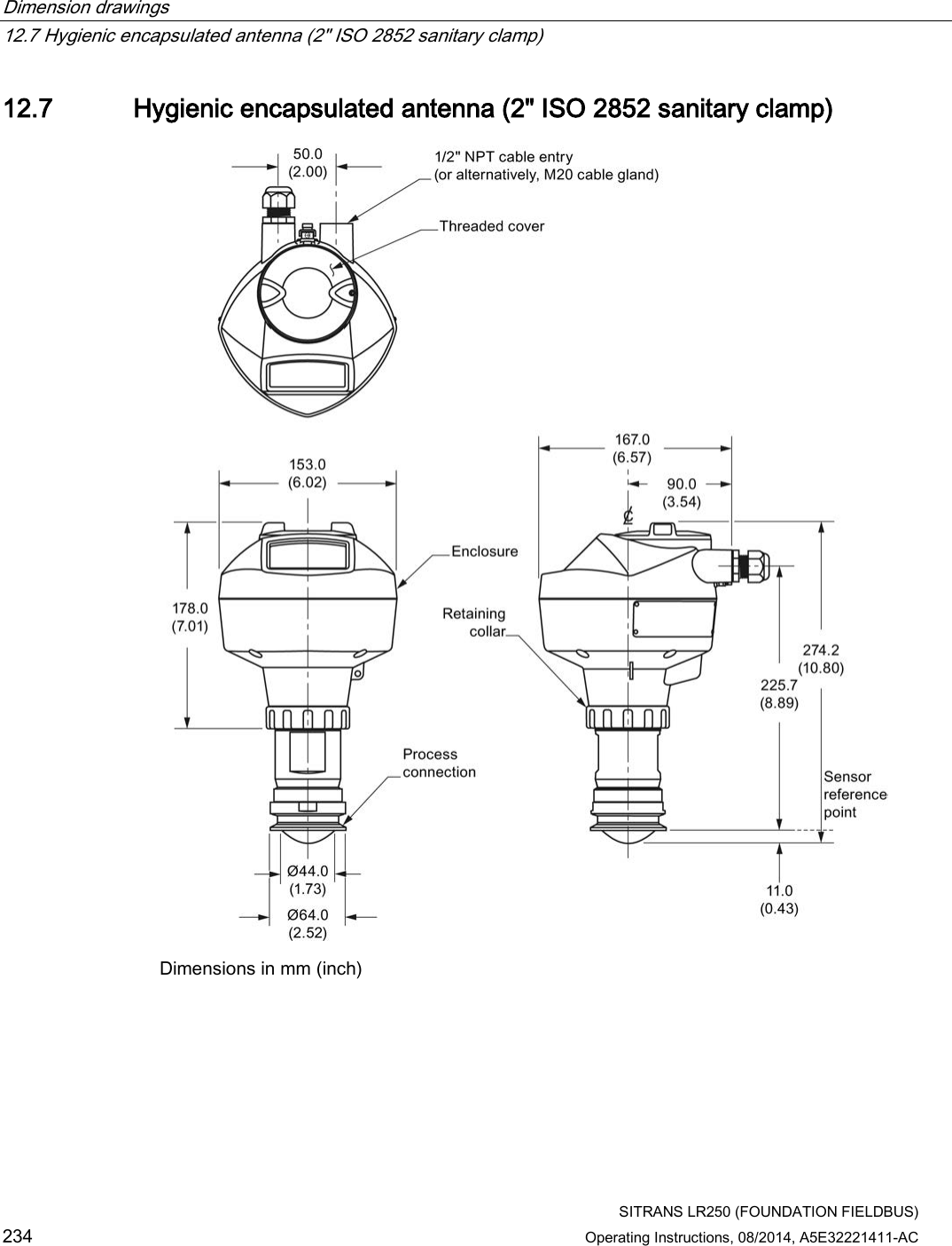
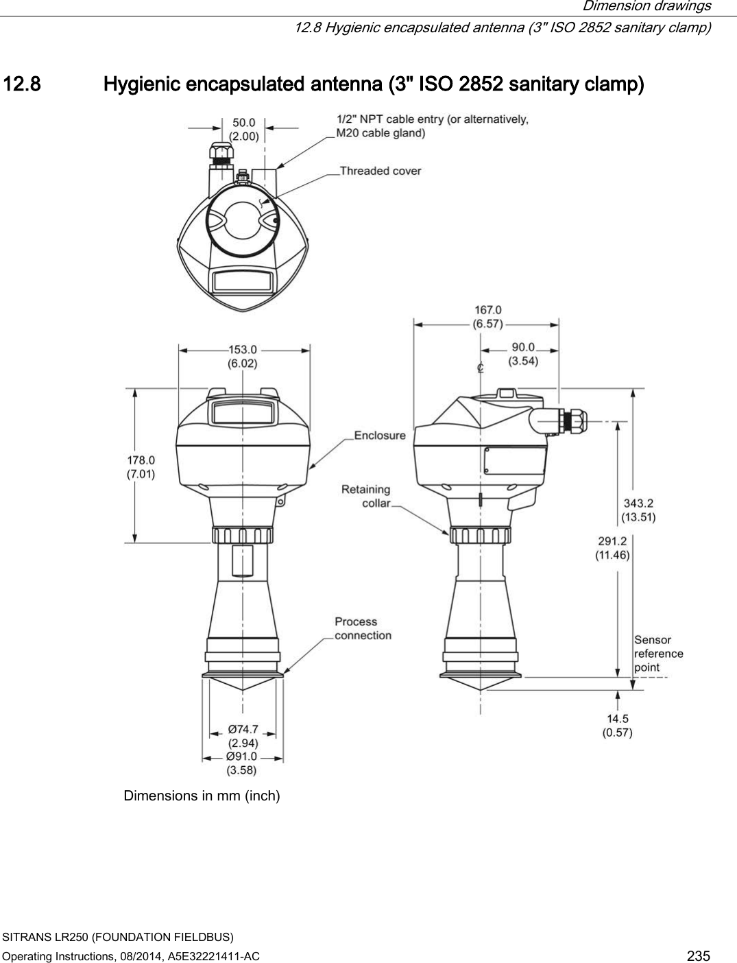
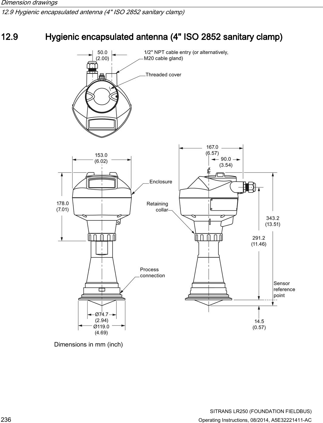
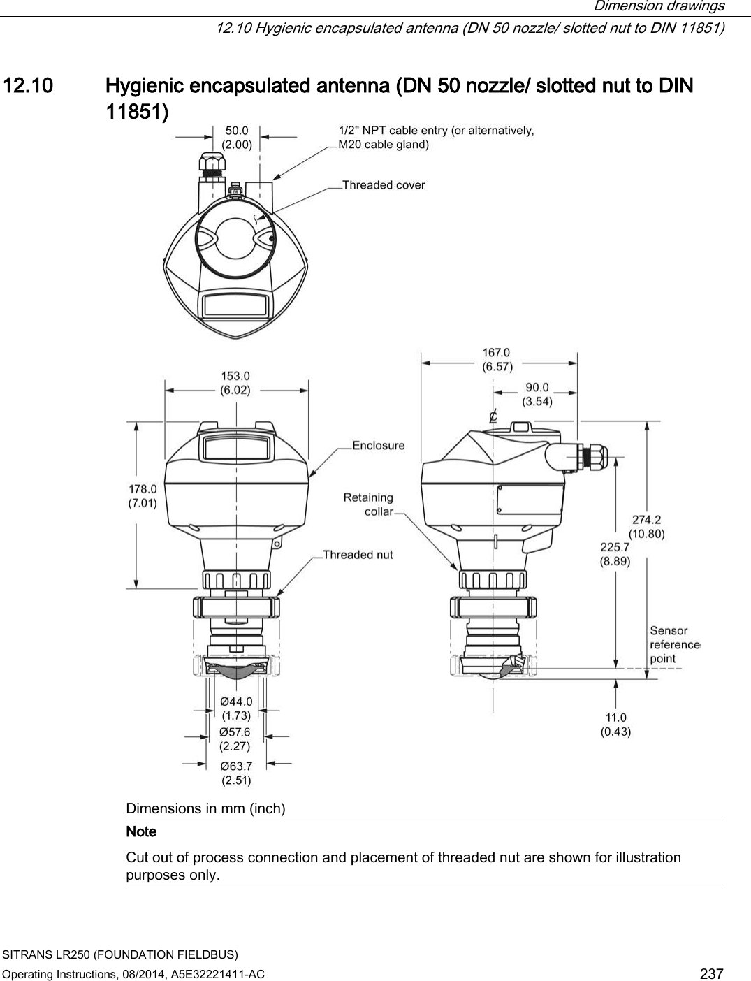
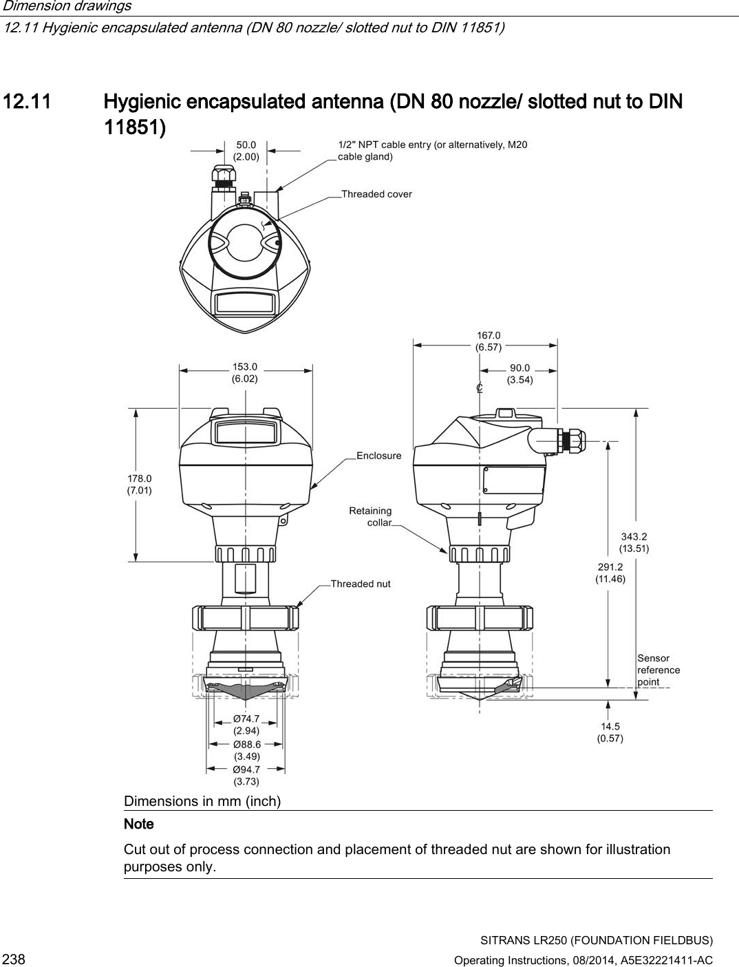
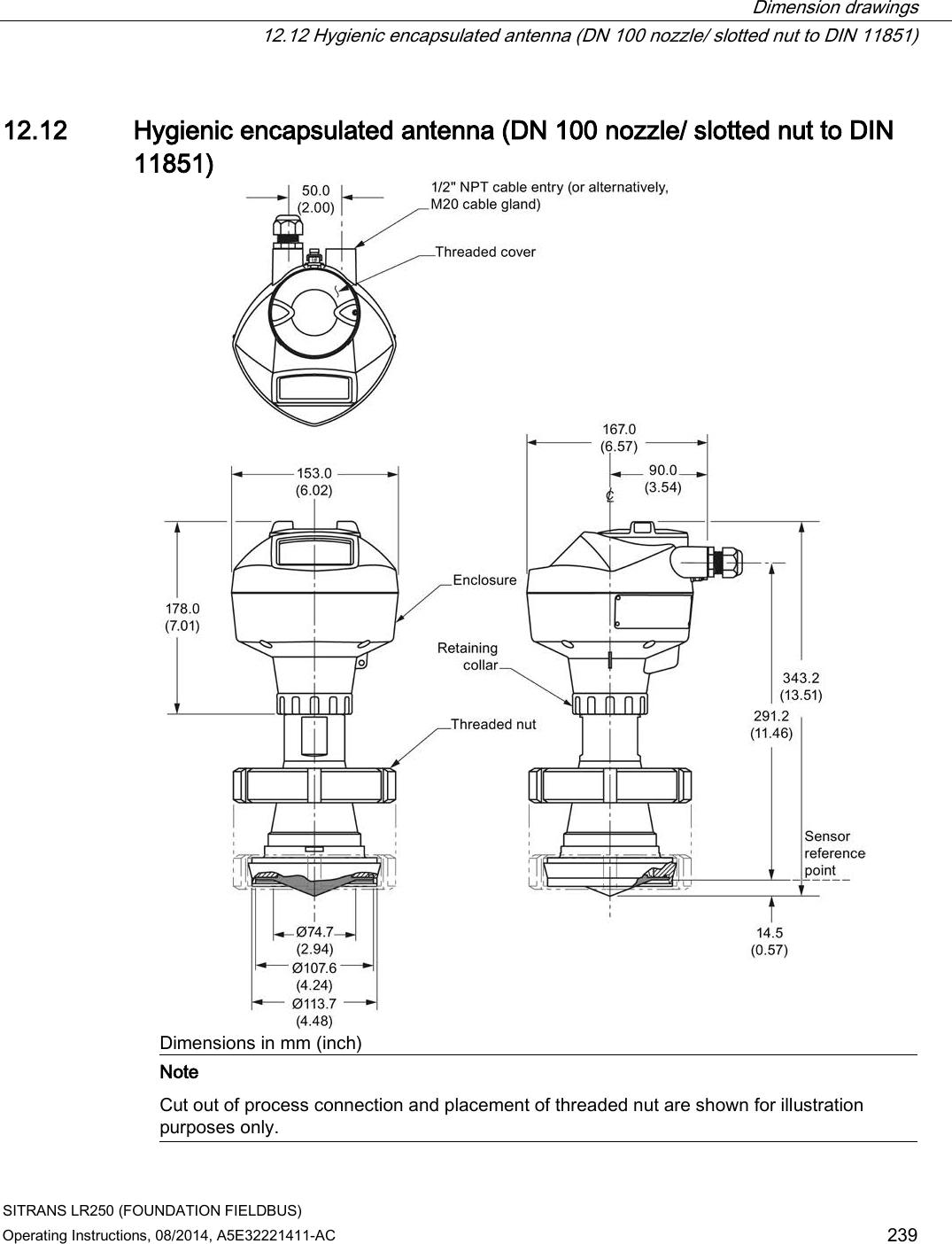
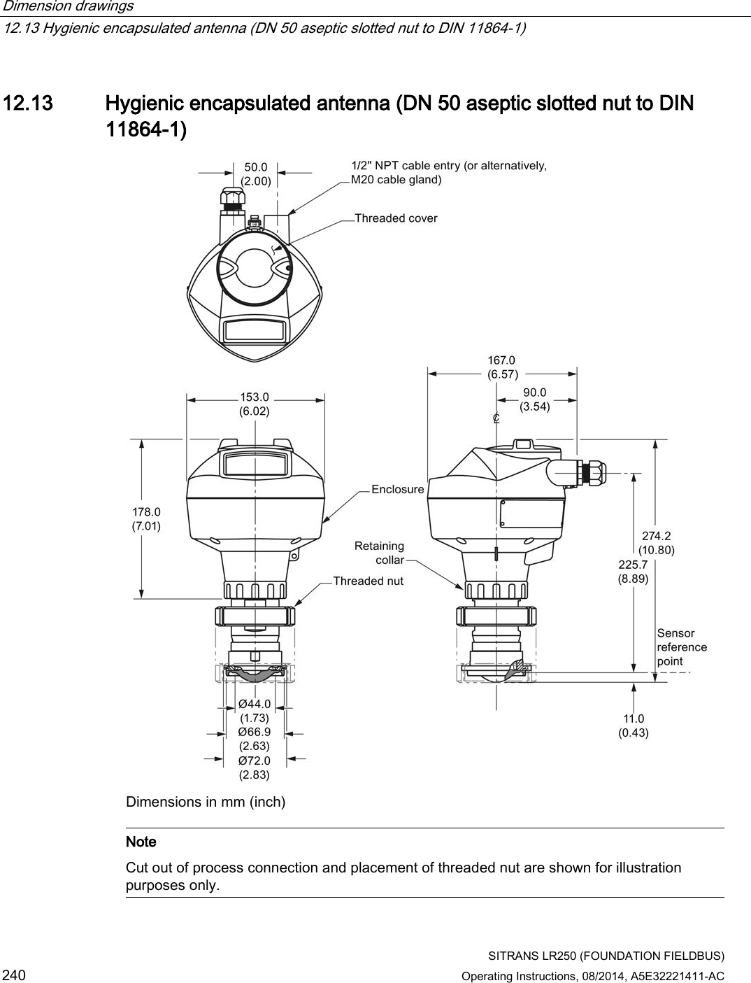
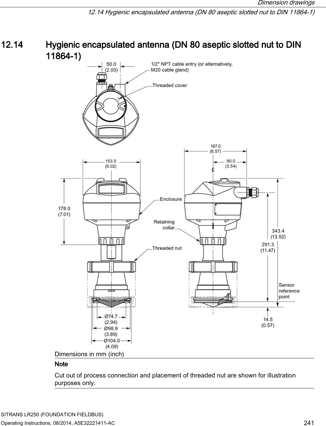
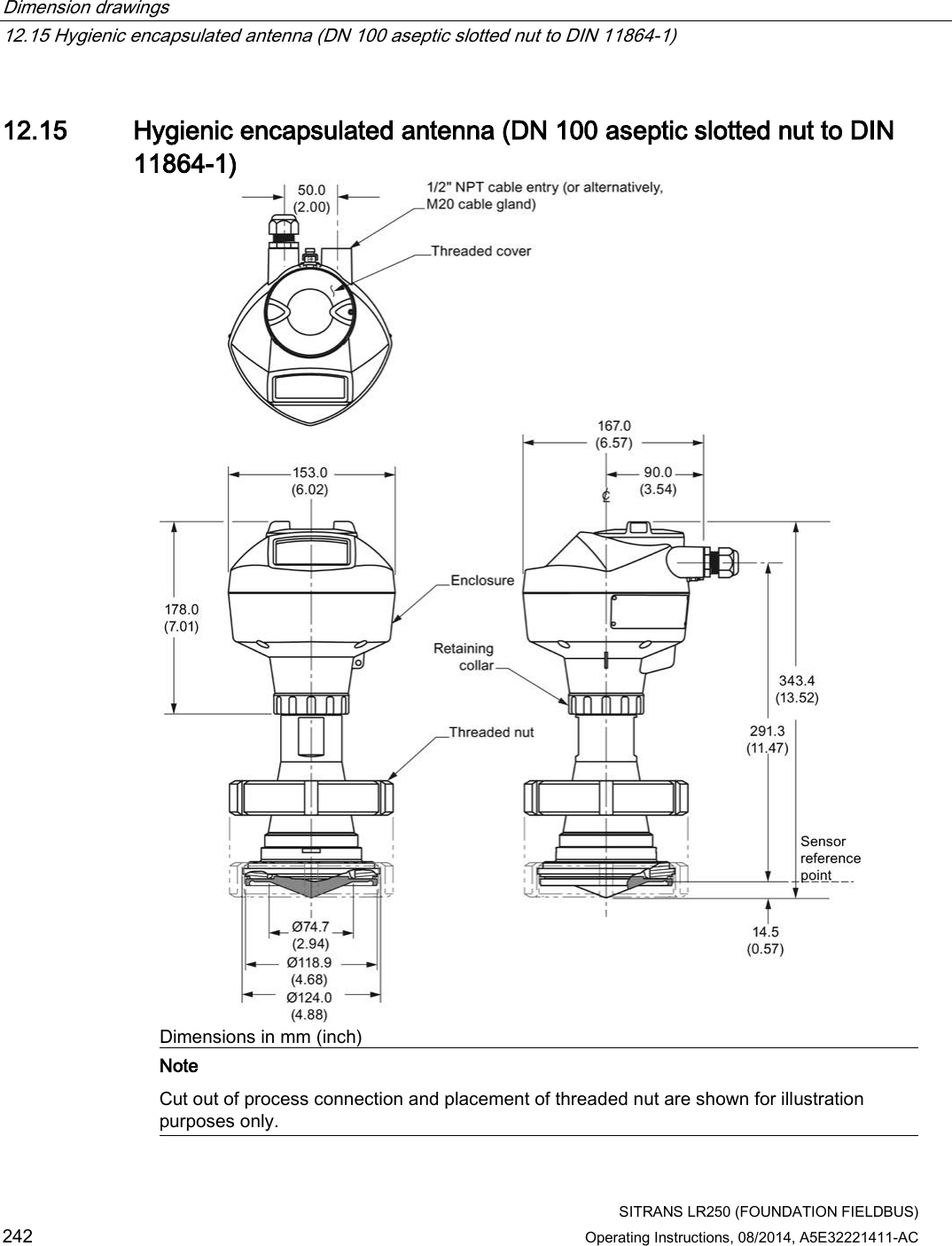
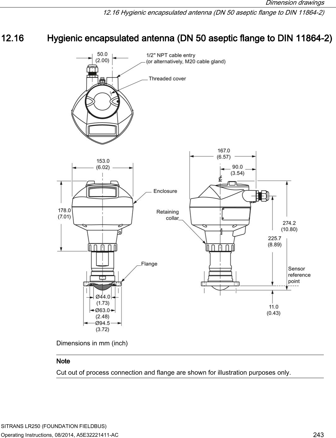
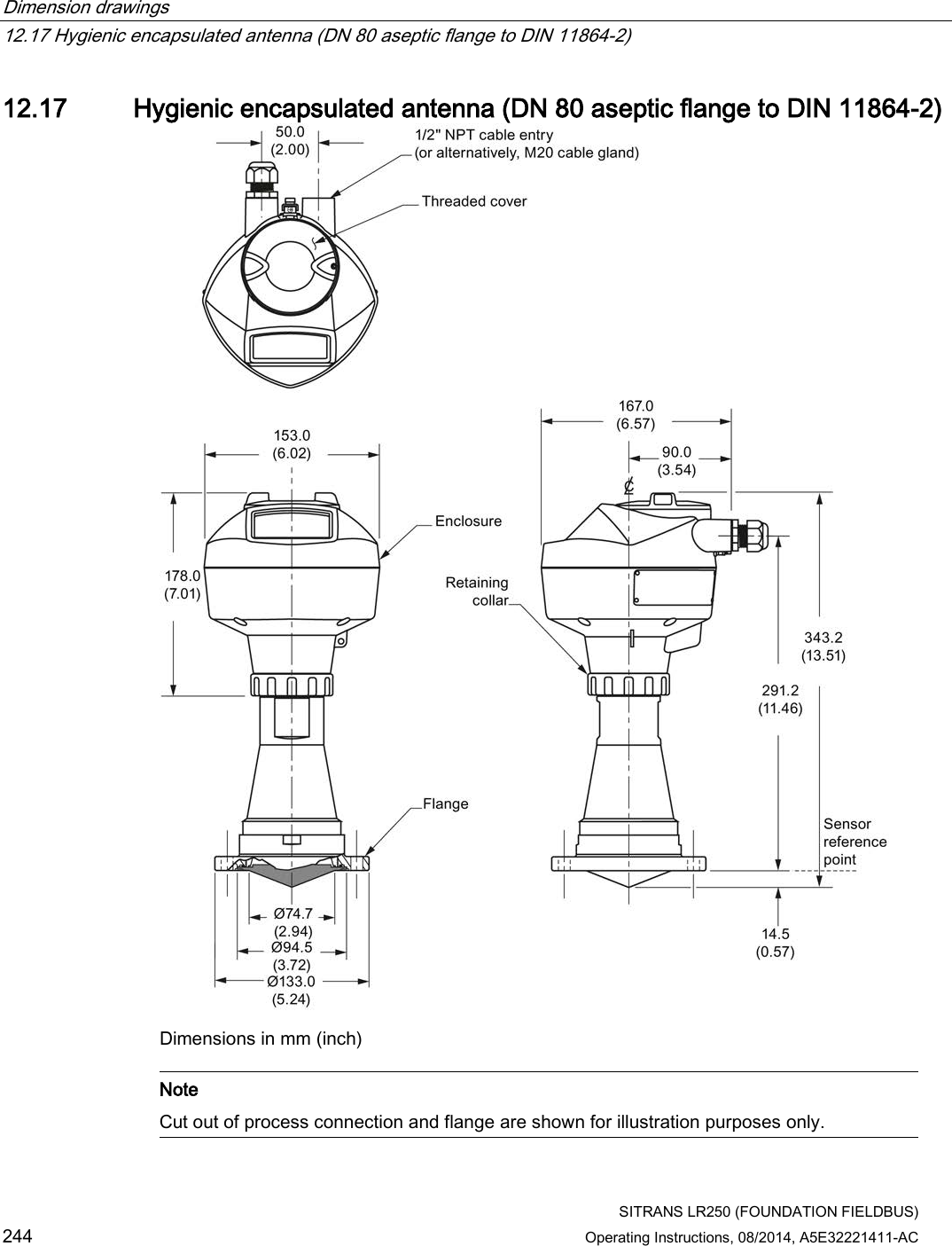
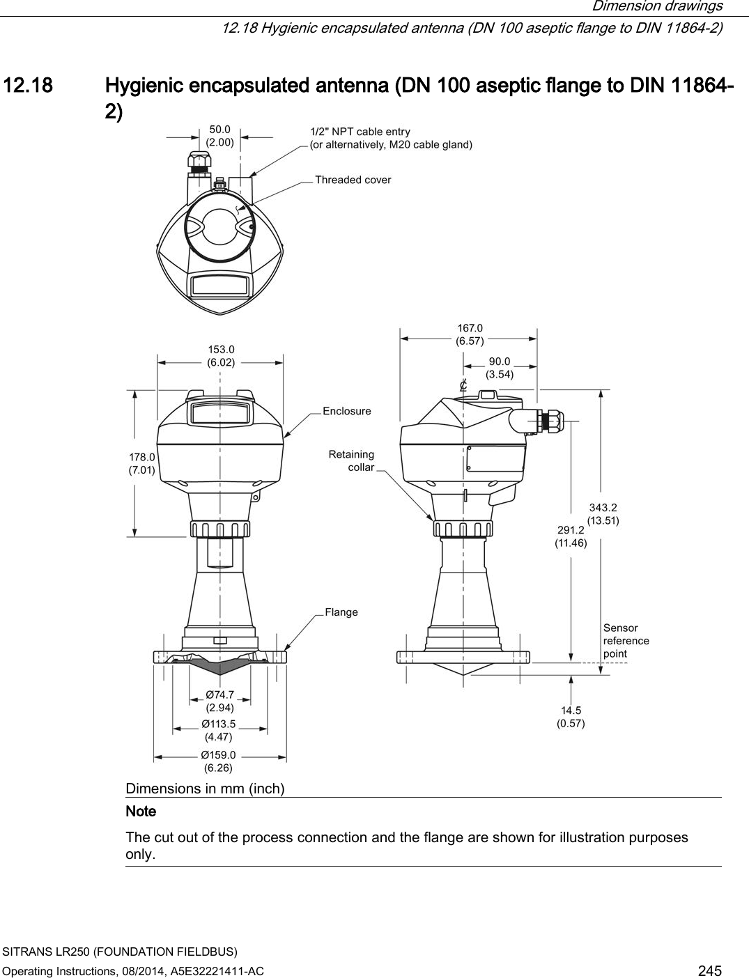
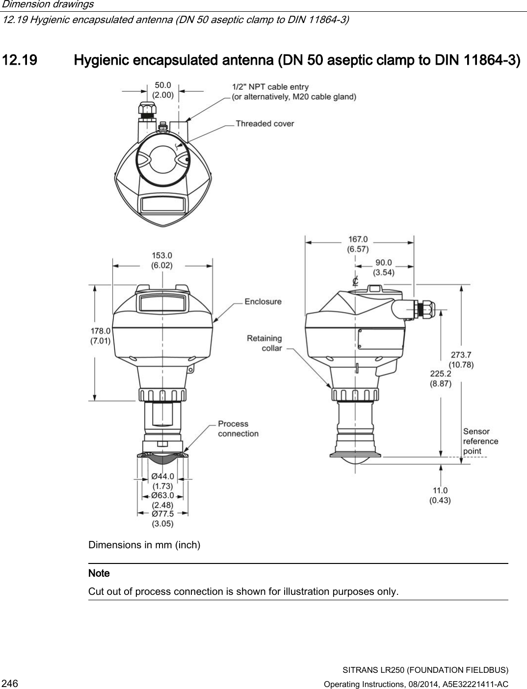
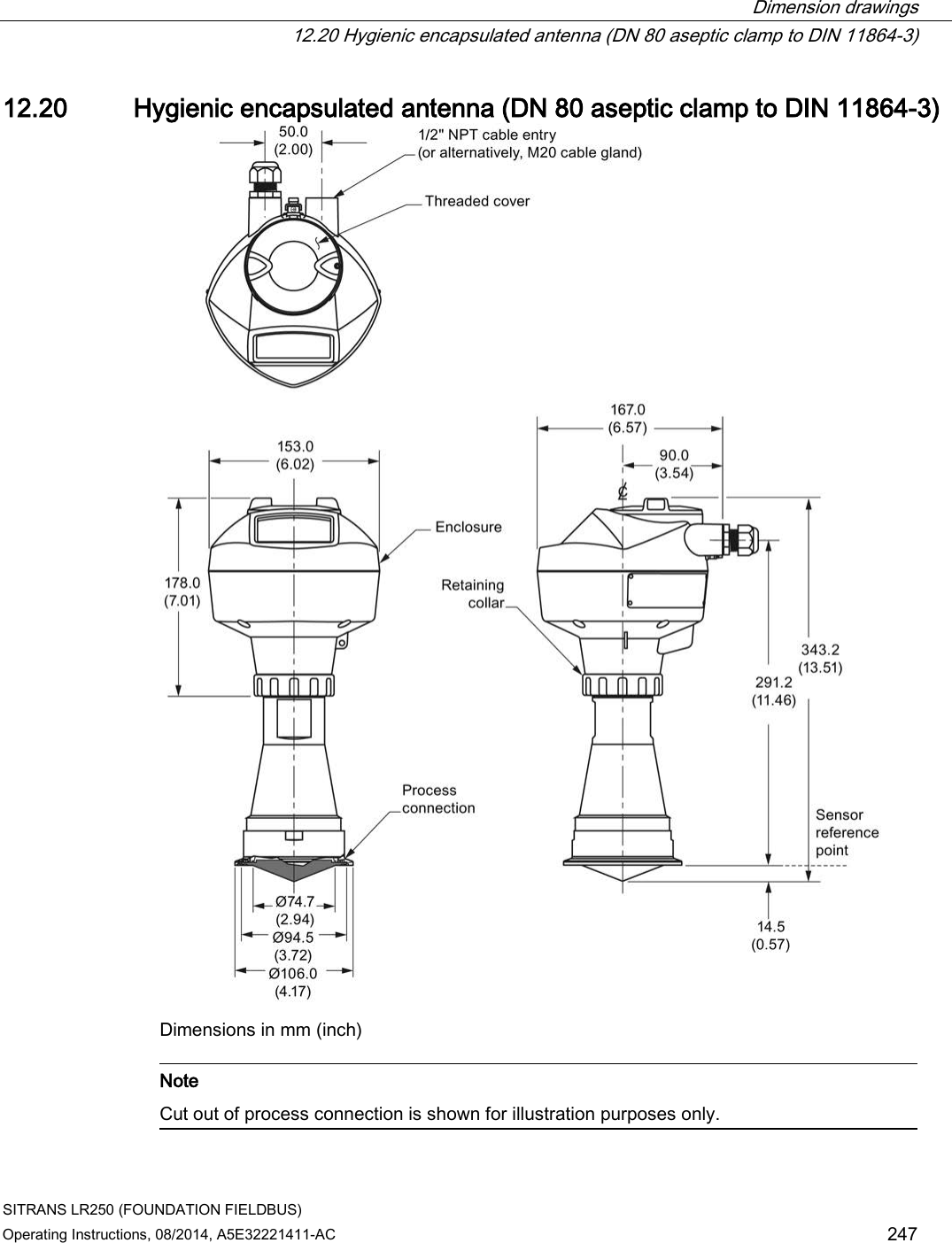
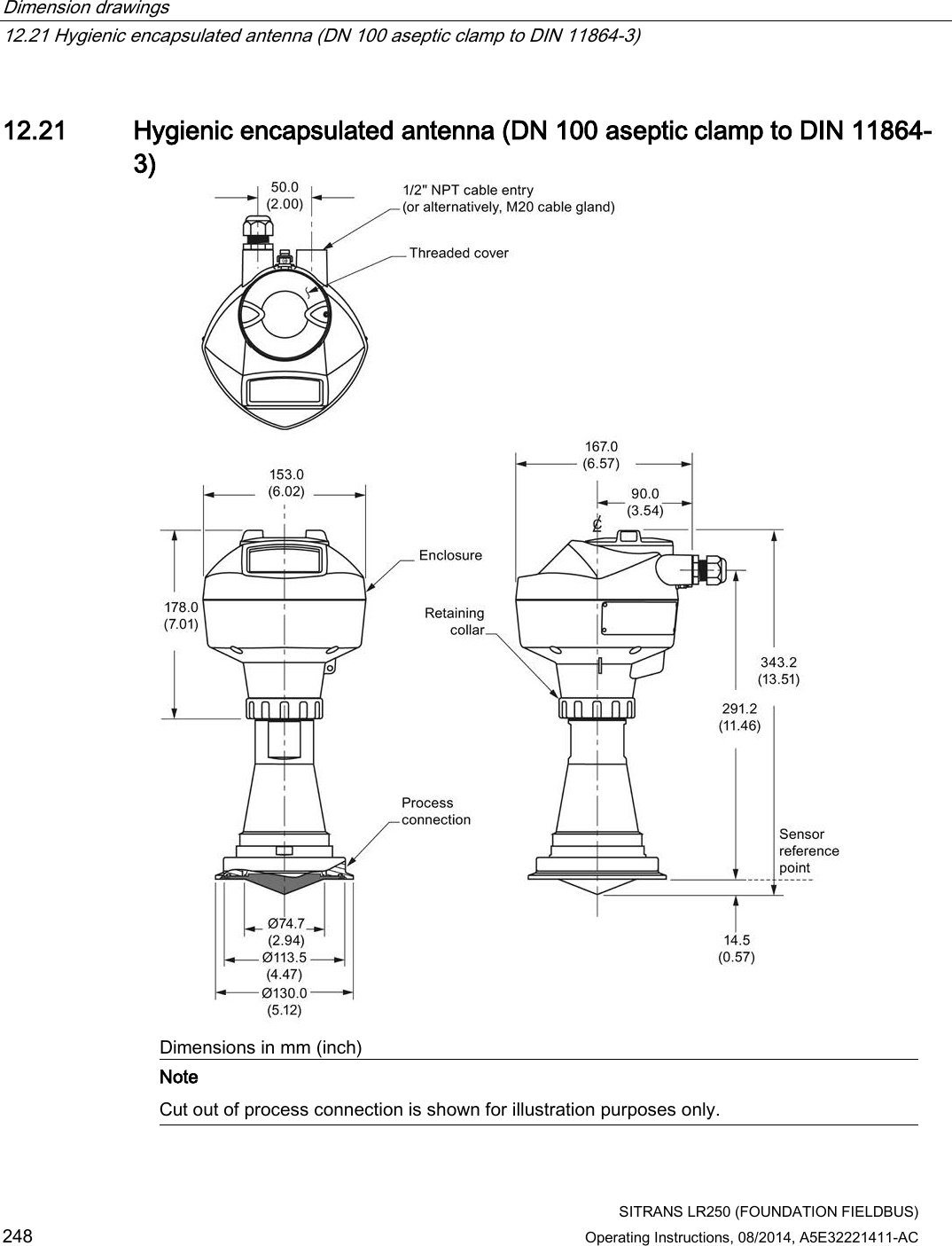
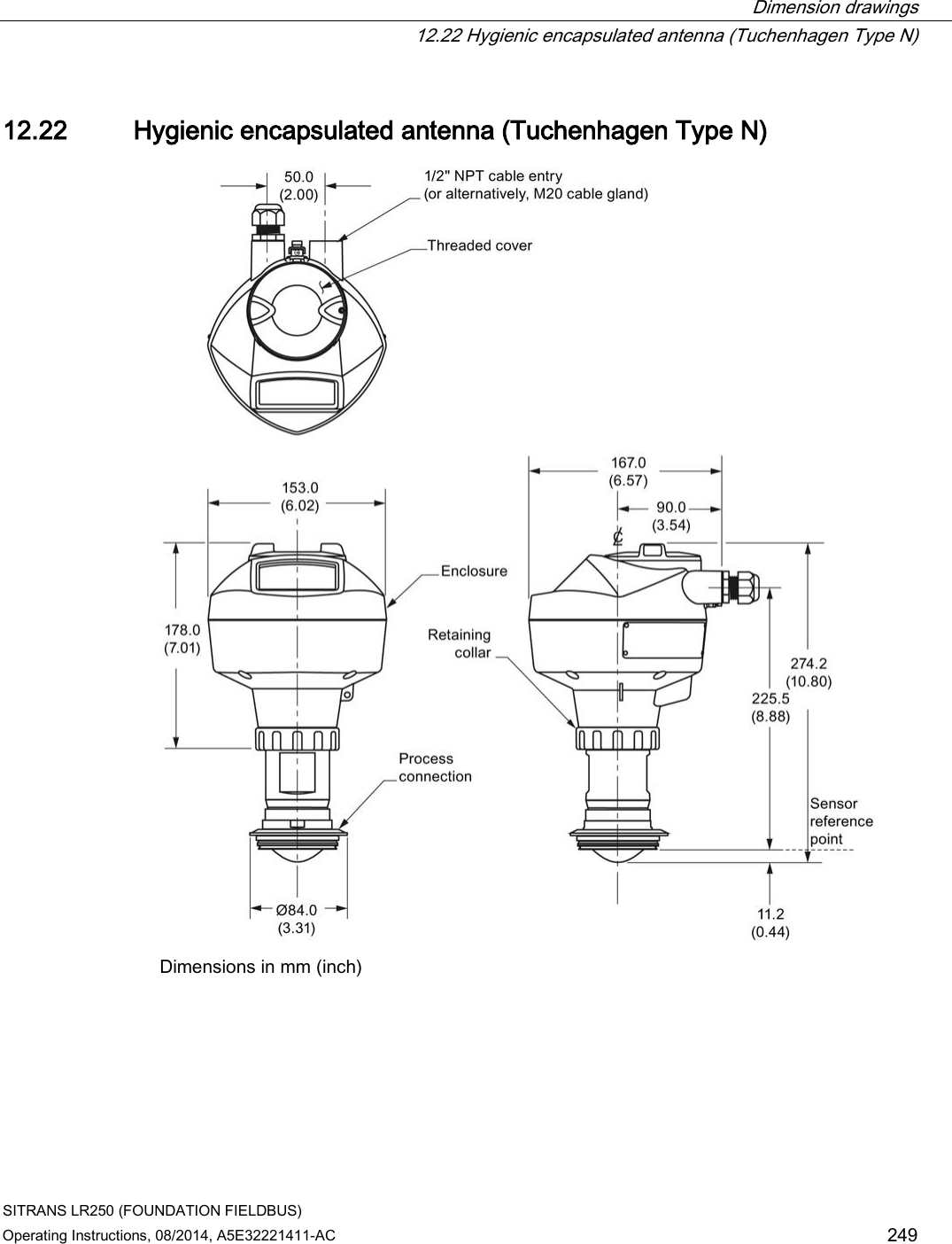
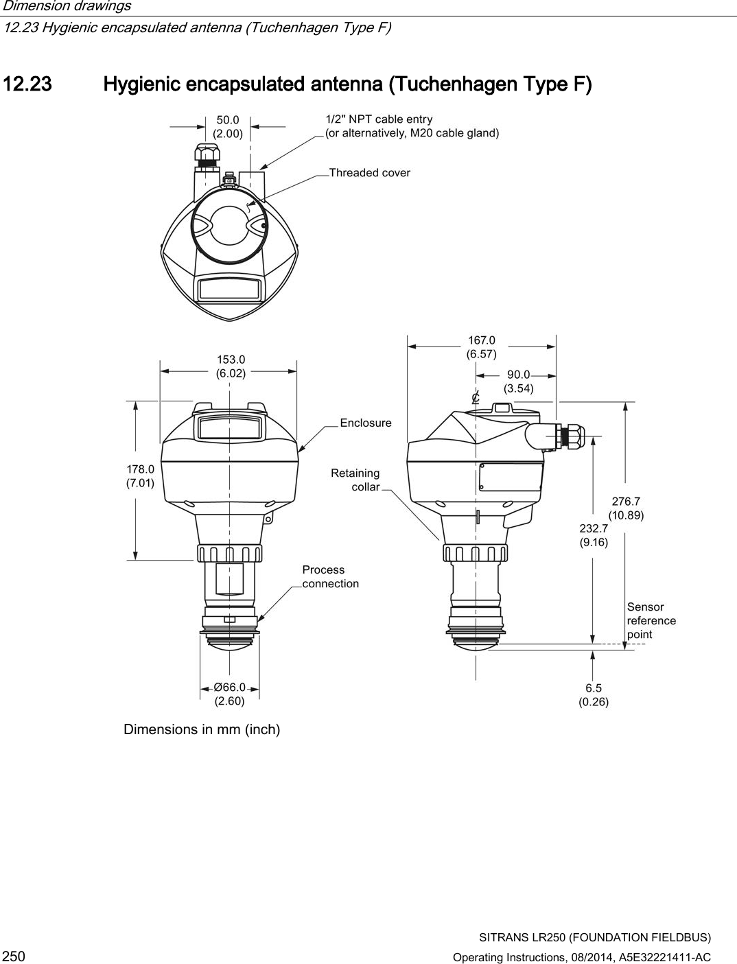
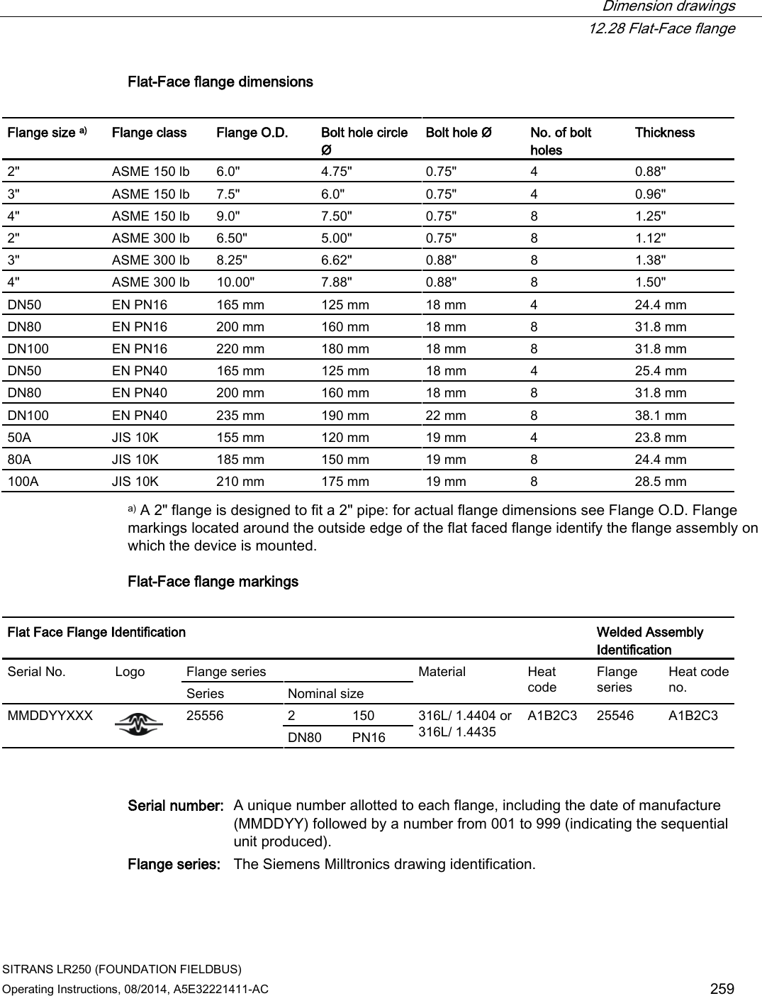
![Technical data 11.3 Interface SITRANS LR250 (FOUNDATION FIELDBUS) Operating Instructions, 08/2014, A5E32221411-AC 215 11.3 Interface Communication: Foundation Fieldbus ITK version 5 Blocks supported: RESOURCE, LTB, AIFB1, AIFB2, LCD, DIAG Block execution time: AIFB - 40 ms Configuration Remote FF host system or Emerson AMS (PC) Local Siemens Milltronics infrared handheld programmer [see Programmer (infrared keypad) (Page 220), or Field Communicator 375 (Page 291)] Display (local)1) graphic LCD, with bar graph (representing level) 1) Display quality will be degraded in temperatures below –25 °C (–13 °F) and above +65 °C (+149 °F). 11.4 Mechanical Process connection: Threaded connection 1.5" NPT (ASME B1.20.1), R (BSPT, EN 10226-1) a) or G (BSPP, EN ISO 228-1) or 2" NPT (ASME B1.20.1), R (BSPT, EN 10226-1) or G (BSPP, EN ISO 228-1) or 3" NPT (ASME B1.20.1), R (BSPT, EN 10226-1) or G (BSPP, EN ISO 228-1) Flange connection (flat-face) Materials 2", 3", 4" (ASME 150 lb, 300 lb) DN50, DN80, DN100 (PN 10/16, PN 25/40) 50A, 80A, 100A (JIS 10K) 316L /1.4404 or 316L /1.4435 stainless steel Flange connection (raised face) Materials DN50, DN80, DN100, DN150 (PN 10/16, PN 25/40) 1.4404 or 1.4435 stainless steel, optional Alloy N06022/2.4602 (Hastelloy®C-22 or equivalent) Flanged encapsulated antenna (FEA) connection (raised face) Materials 2, 3, 4, 6" (ASME 150 lb); DN50, DN80, DN100, DN150 (PN10/16); 50A, 80A, 100A, 150A (JIS 10K) 316L /1.4404 or 316L /1.4435 stainless steel Hygienic encapsulated antenna (HEA) connection ISO 2852 (2, 3, 4") DIN 11851 (DN50, DN80, DN100) DIN 11864-1/2/3 (DN50, DN80, DN100) Tuchenhagen (Type F [50 mm and Type N [68 mm]) 316L /1.4404 or 316L /1.4435 stainless steel](https://usermanual.wiki/Siemens-Canada-Siemens-Milltronics-Process-Instruments/LR250.User-Manual-4/User-Guide-2277919-Page-73.png)
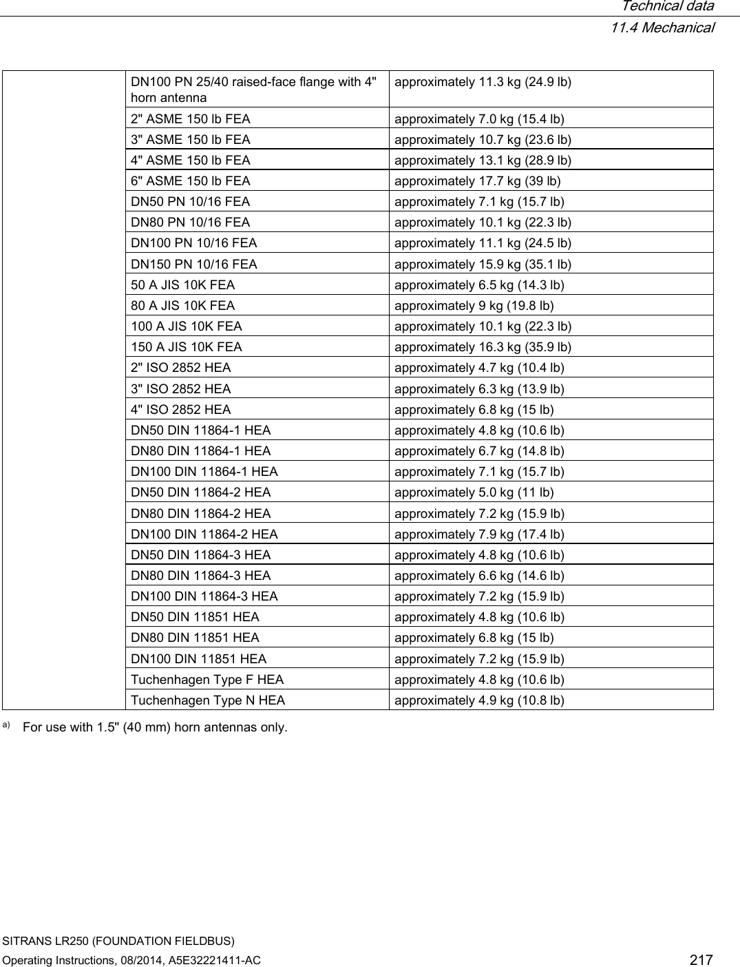
![Technical data 11.4 Mechanical SITRANS LR250 (FOUNDATION FIELDBUS) 216 Operating Instructions, 08/2014, A5E32221411-AC Materials ISO 2852 (2, 3, 4") DIN 11864-3 (DN50, DN80, DN100) clamp: 304/1.4301 stainless steel Tuchenhagen (Type F [50 mm] and Type N [68 mm]) 316L /1.4404 or 316L /1.4435 stainless steel clamp: 304/1.4301 stainless steel nut connection: 303/1.4305 stainless steel DIN 11851/11864-1 (DN50, DN80. DN100) captive slotted nut connection: 304L/1.4307 DIN 11864-2 (DN50, DN80. DN100) mounting nuts and bolts: 304/1.4301 stainless steel Antenna: Horn Materials standard 1.5" (40 mm), 2" (50 mm), 3" (80 mm), and 4" (100 mm) horn, optional 100 mm (4") horn extension 316L stainless steel with PTFE emitter optional Alloy N06022/2.4602 (Hastelloy®C-22 or equivalent) with PTFE emitter Threaded PVDF antenna Wetted materials 2" (50 mm) PVDF (Polyvinylidene fluoride) Flanged encapsulated antenna Wetted materials 316L /1.4404 or 316L /1.4435 stainless steel TFMTM 1600 PTFE lens Hygienic encapsulated antenna Wetted material 316L/1.4404 or 316L/1.4435 stainless steel TFMTM 1600 PTFE (plus chosen seal) Enclosure Construction aluminum, polyester powder-coated Conduit entry 2 x M20x1.5, or 2 x ½" NPT Ingress protection Type 4X/NEMA 4X, Type 6/NEMA 6, IP67, IP68 Weight (excluding extensions): 1.5" threaded connection with 1.5" horn antenna approximately 5.1 kg (11.2 lb) 2" threaded connection with 2" horn antenna approximately 5.5 kg (12.1 lb) 3" threaded connection with 3" horn antenna approximately 7.0 kg (15.4 lb) 2" threaded PVDF antenna approximately 3.3 kg (7.27 lb) DN50 PN 10/16 or 2" 150 lb flat-face flange with 2" horn antenna approximately 8 kg (17.6 lb) DN100 PN 25/40 or 4" ASME 300 lb flat-face flange with 4" horn antenna approximately 17.4 kg (38.3 lb) DN50 PN 10/16 raised-face flange with 2" horn antenna approximately 6 kg (13.2 lb)](https://usermanual.wiki/Siemens-Canada-Siemens-Milltronics-Process-Instruments/LR250.User-Manual-4/User-Guide-2277919-Page-74.png)
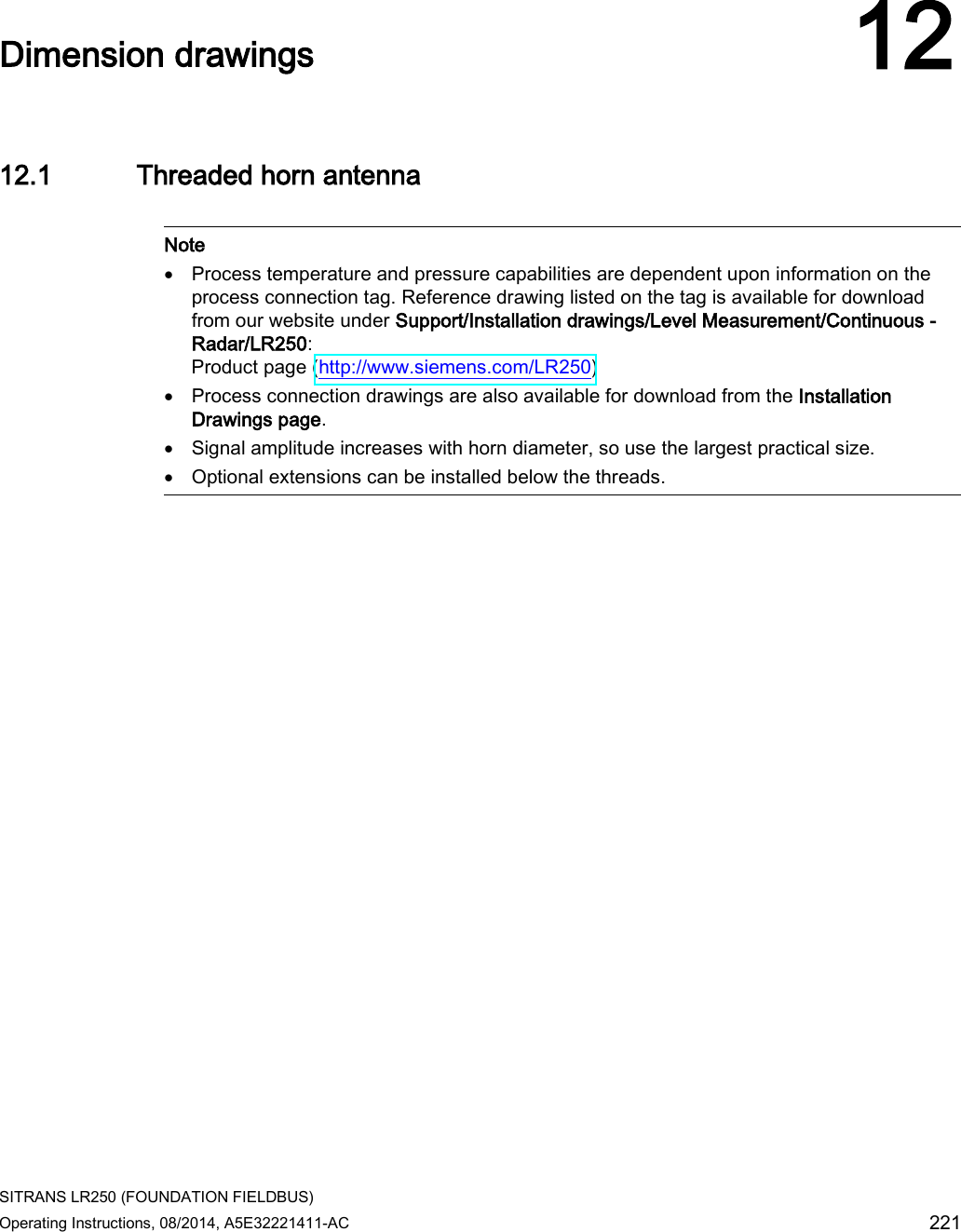
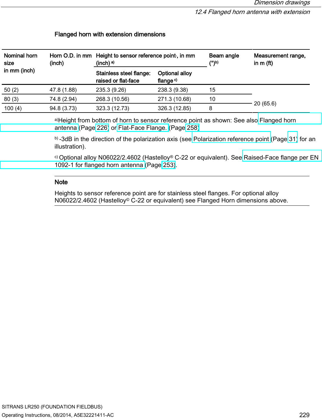
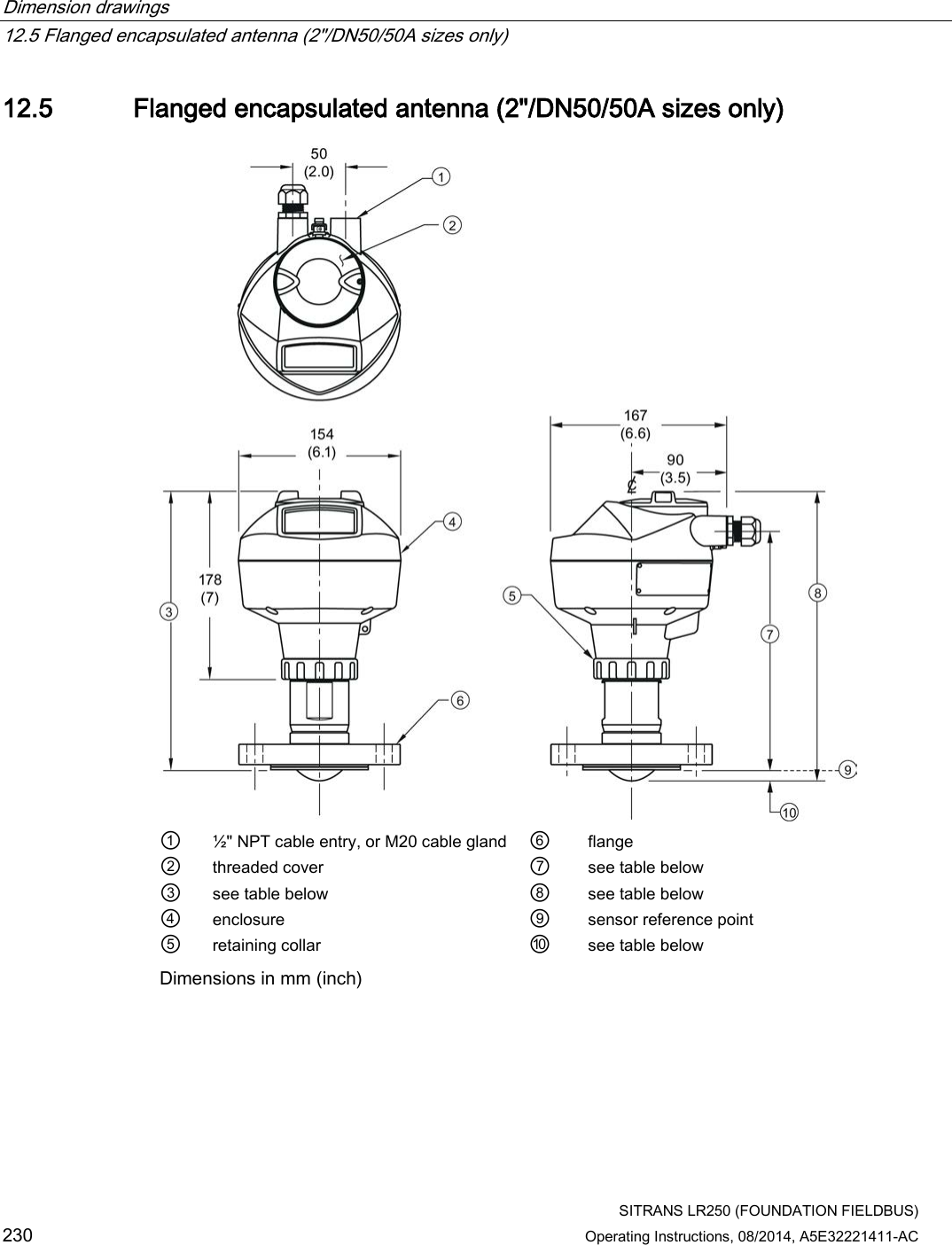
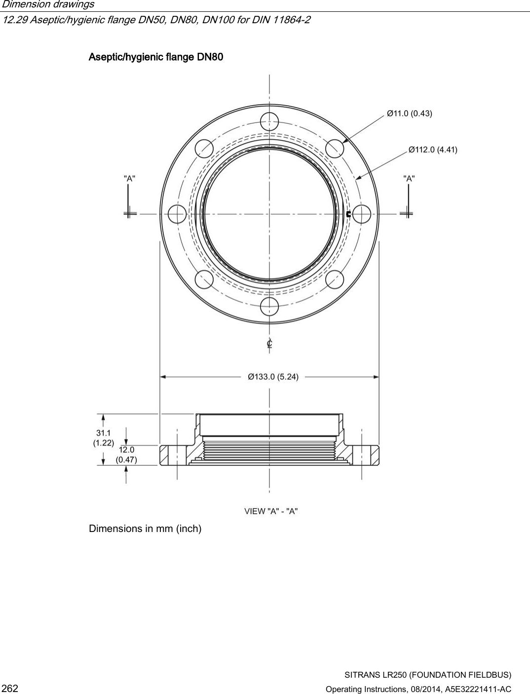
![Dimension drawings 12.5 Flanged encapsulated antenna (2"/DN50/50A sizes only) SITRANS LR250 (FOUNDATION FIELDBUS) Operating Instructions, 08/2014, A5E32221411-AC 231 Flanged encapsulated antenna (2"/DN50/50A) dimensions Flange size ③ mm (inch) ⑦ mm (inch) ⑧ mm (inch) ⑩ mm (inch)1) 2"/DN50/50A 263 (10.35) 223 (8.78) 274 (10.79) 11 (0.43) 1) Height from tip of lens to sensor reference point as shown. Flange size Flange class Flange O.D. [mm (inch)] Antenna aperture size [mm (inch)] Beam angle (°)1) Measurement range [m (ft)] 2" 150 LB 152 (5.98) 50 (1.97) 12.8 10 (32.8)2) DN50 PN10/16 165 (6.50) 50A 10K 155 (6.10) 1) -3 dB in the direction of the polarization axis. 2) 20m if installed in stillpipe See Raised-Face Flange per EN 1092-1, (Page 255)and Polarization reference point (Page 31).](https://usermanual.wiki/Siemens-Canada-Siemens-Milltronics-Process-Instruments/LR250.User-Manual-4/User-Guide-2277919-Page-89.png)
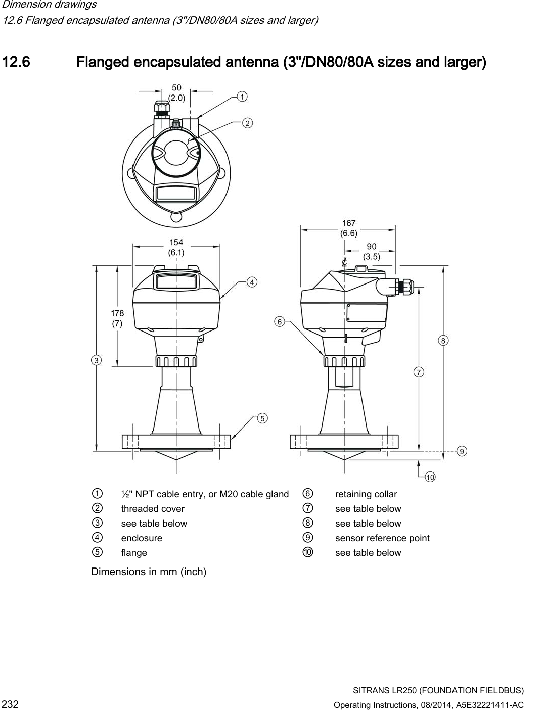
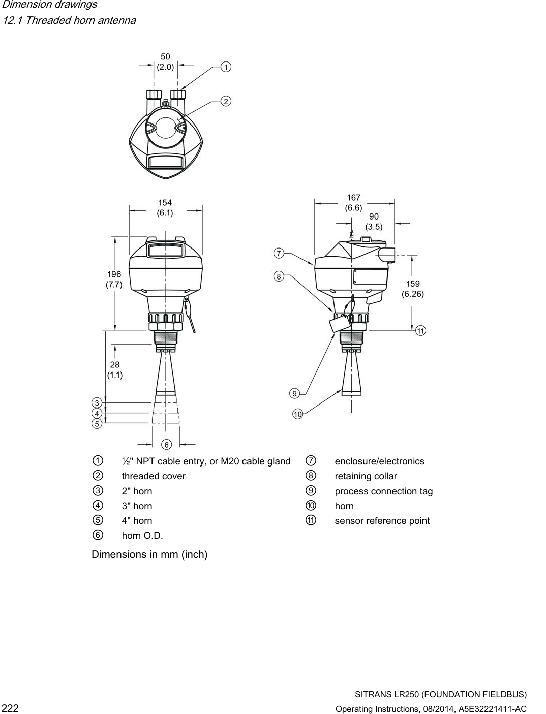
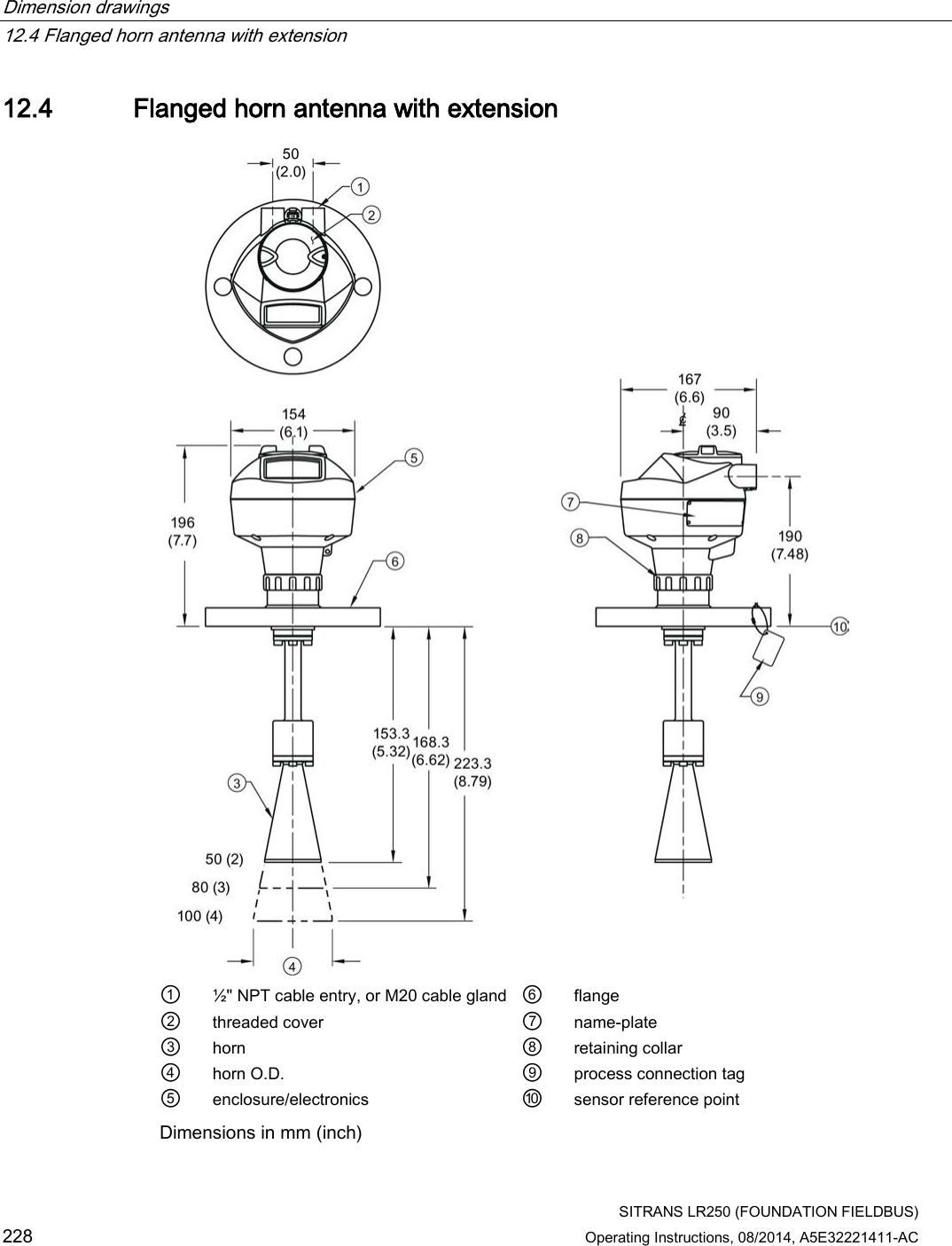
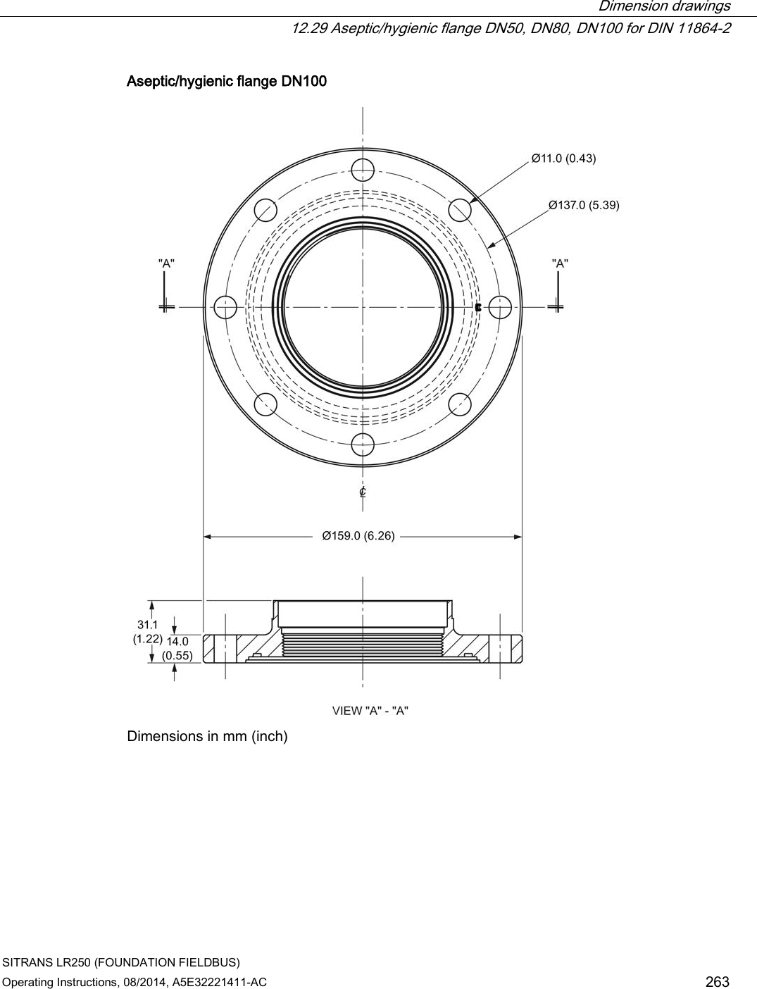
![Dimension drawings 12.6 Flanged encapsulated antenna (3"/DN80/80A sizes and larger) SITRANS LR250 (FOUNDATION FIELDBUS) Operating Instructions, 08/2014, A5E32221411-AC 233 Flanged encapsulated antenna (3"/DN80/80A and larger) dimensions Flange size ③ mm (inch) ⑦ mm (inch) ⑧ mm (inch) ⑩ mm (inch)1) 3"/DN80/80A 328 (12.91) 288 (11.34) 343 (13.50) 15 (0.59) 4"/DN100/100A 328 (12.91) 288 (11.34) 343 (13.50) 13 (0.51) 6"/DN150/150A 333 (13.11) 293 (11.54) 348 (13.70) 15 (0.59) 1) Height from tip of lens to sensor reference point as shown. See also Raised-Face Flange per EN 1092-1. Flange size Flange class Flange O.D. [mm (inch)] Antenna aperture size [mm (inch)] Beam angle (°)1) Measurement range [m (ft)] 3" 150 LB 190 (7.48) 75 (2.95) 9.6 20 (65.6) DN80 PN10/16 200 (7.87) 80A 10K 185 (7.28) 4" 150 LB 230 (9.06) 75 (2.95) 9.6 20 (65.6) DN100 PN10/16 220 (8.66) 100A 10K 210 (8.27) 6" 150 LB 280 (11.02) 75 (2.95) 9.6 20 (65.6) DN150 PN10/16 285 (11.22) 150A 10K 280 (11.02) 1) -3 dB in the direction of the polarization axis. See Raised-Face Flange per EN 1092-1 (Page 255), and Polarization reference point (Page 31).](https://usermanual.wiki/Siemens-Canada-Siemens-Milltronics-Process-Instruments/LR250.User-Manual-4/User-Guide-2277919-Page-91.png)

![Dimension drawings 12.26 Raised-Face flange per EN 1092-1 for flanged horn antenna SITRANS LR250 (FOUNDATION FIELDBUS) 254 Operating Instructions, 08/2014, A5E32221411-AC Pipe size Flange bolt hole pattern ⑤ Flange O.D. (mm) ③ Bolt hole circle Ø (mm) ② Bolt hole Ø (mm) No. of bolts ① Angle of adjacent bolt holes ⑧ Facing Ø (mm) ⑩ Thickness (mm) DN50 PN10/PN16 165 125 18 4 90 102 18 DN80 PN10/PN16 200 160 18 8 45 138 20 DN100 PN10/PN16 220 180 18 8 45 158 20 DN150 PN10/PN16 285 240 22 8 45 212 22 DN50 PN25/PN40 165 160 18 4 90 138 20 DN80 PN25/PN40 200 160 18 8 45 138 24 DN100 PN25/PN40 235 190 22 8 45 162 24 DN150 PN25/PN40 300 250 26 8 45 218 28 Raised-Face flange markings Blind Flange Markings (Optional Manufacturer’s Logo [optional]; Flange Standard; Nominal Size; Material; Heat Code) Machining Identification Welded Assembly Identification a) Serial no. Logo Flange series Flange series Heat Code no. Facing Manufacturer’s logo; EN 1092-1 05 ‘B1’; ‘DN50’ ‘PN16’ ‘1.4404 or 1.4435’ A1B2C3 mmddyyxxx xxxxx xxxxx A1B2C3 RF a) When flange material is alloy N06022/2.4602, additional material and heat code identification is provided. The flange markings are located around the outside edge of the flange. Serial number: a unique number allotted to each flange, including the date of manufacture (MMDDYY) followed by a number from 001 to 999 (indicating the sequential unit produced). Flange series: the Siemens Milltronics drawing identification. Heat code: a flange material batch code identification.](https://usermanual.wiki/Siemens-Canada-Siemens-Milltronics-Process-Instruments/LR250.User-Manual-4/User-Guide-2277919-Page-112.png)
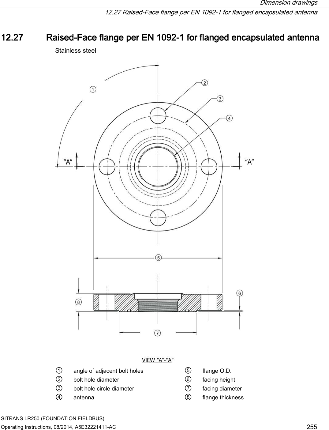
![Dimension drawings 12.27 Raised-Face flange per EN 1092-1 for flanged encapsulated antenna SITRANS LR250 (FOUNDATION FIELDBUS) 256 Operating Instructions, 08/2014, A5E32221411-AC Raised-Face flange dimensions Pipe size Flange class ⑤ Flange O.D. [mm (inch)] ③ Bolt hole circle Ø [mm (inch)] ② Bolt hole Ø [mm (inch)] No. of bolt holes ① Angle of adjacent bolt holes ⑦ Facing Ø [mm (inch)] ⑨ Flange thickness [mm (inch)] ⑥ Flange facing thickness [mm (inch)] 2" 150 LB 152 (5.98) 120.7 (4.75) 19 (0.75) 4 90 92.1 (3.63) 20.6 (0.81) 1.5 (0.06) 3" 190 (7.48) 152.4 (6.00) 127 (5.00) 25.9 (1.02) 2 (0.08) 4" 230 (9.06) 190.5 (7.50) 8 45 157.2 (6.19) 2 (0.08) 6" 280 (11.02) 241.3 (9.50) 22.2 (0.87) 215.9 (8.50) 26.9 (1.06) 1.5 (0.06) DN50 PN10/16 155 (6.10) 125 (4.92) 18 (0.71) 4 90 102 (4.02) 18 (0.71) 2 (0.08) DN80 200 (7.87) 160 (6.30) 8 45 138 (5.43) 20 (0.79) 2 (0.08) DN100 220 (8.66) 180 (7.09) 158 (6.22) 2 (0.08) DN150 285 (11.22) 240 (9.45) 22 (0.87) 212 (8.35) 22 (0.87) 2 (0.08) 50A 10K 155 (6.10) 120 (4.72) 19 (0.75) 4 90 96 (3.78) 16 (0.63) 2 (0.08) 80A 185 (7.28) 150 (5.91) 8 45 126 (4.96) 18 (0.71) 2 (0.08) 100A 210 (8.27) 175 (6.89) 151 (5.94) 2 (0.08) 150A 280 (11.02) 240 (9.45) 23 (0.91) 212 (8.35) 22 (0.87) 2 (0.08)](https://usermanual.wiki/Siemens-Canada-Siemens-Milltronics-Process-Instruments/LR250.User-Manual-4/User-Guide-2277919-Page-114.png)
![Dimension drawings 12.27 Raised-Face flange per EN 1092-1 for flanged encapsulated antenna SITRANS LR250 (FOUNDATION FIELDBUS) Operating Instructions, 08/2014, A5E32221411-AC 257 Raised-Face flange markings Blind Flange Markings (Optional Manufacturer’s Logo [optional]; Flange Standard; Nominal Size; Material; Heat Code) Machining Identification Welded Assembly Identification Serial no. Logo Flange series Flange series Heat Code no. Facing Manufacturer’s logo; EN 1092-1 05 ‘B1’; ‘DN50’ ‘PN16’ ‘1.4404 or 1.4435’ A1B2C3 mmddyyxxx xxxxx xxxxx A1B2C3 RF The flange markings are located around the outside edge of the flange. Serial number: a unique number allotted to each flange, including the date of manufacture (MMDDYY) followed by a number from 001 to 999 (indicating the sequential unit produced). Flange series: the Siemens Milltronics drawing identification. Heat code: a flange material batch code identification.](https://usermanual.wiki/Siemens-Canada-Siemens-Milltronics-Process-Instruments/LR250.User-Manual-4/User-Guide-2277919-Page-115.png)
![SITRANS LR250 (FOUNDATION FIELDBUS) Operating Instructions, 08/2014, A5E32221411-AC 265 Appendix A: Technical reference A Note Where a number follows the parameter name [for example, Master Reset (4.1.)] this is the parameter access number via the handheld programmer. See Parameter Reference (Page 143) for a complete list of parameters. A.1 Principles of operation SITRANS LR250 is a 2-wire 25 GHz pulse radar level transmitter for continuous monitoring of liquids and slurries. (The microwave output level is significantly less than that emitted from cellular phones.) Radar level measurement uses the time of flight principle to determine distance to a material surface. The device transmits a signal and waits for the return echo. The transit time is directly proportional to the distance from the material. Pulse radar uses polarized electromagnetic waves. Microwave pulses are emitted from the antenna at a fixed repetition rate, and reflect off the interface between two materials with different dielectric constants (the atmosphere and the material being monitored). Electromagnetic wave propagation is virtually unaffected by temperature or pressure changes, or by changes in the vapor levels inside a vessel. Electromagnetic waves are not attenuated by dust. SITRANS LR250 consists of an enclosed electronic circuit coupled to an antenna and process connection. The electronic circuit generates a radar signal (25 GHz) that is directed to the antenna. The signal is emitted from the antenna, and the reflected echoes are digitally converted to an echo profile. The profile is analyzed to determine the distance from the material surface to the sensor reference point. See Dimension drawings (Page 221). This distance is used as a basis for the display of material level and mA output.](https://usermanual.wiki/Siemens-Canada-Siemens-Milltronics-Process-Instruments/LR250.User-Manual-4/User-Guide-2277919-Page-123.png)
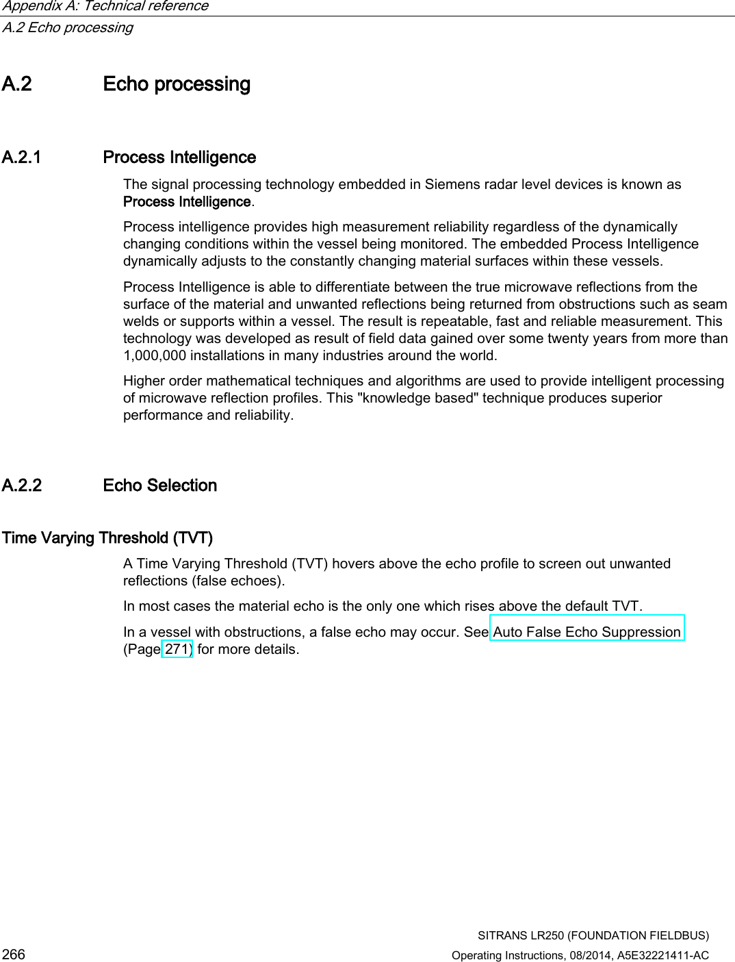
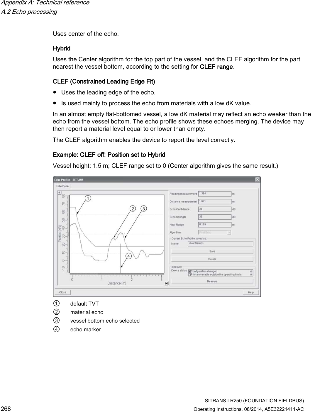
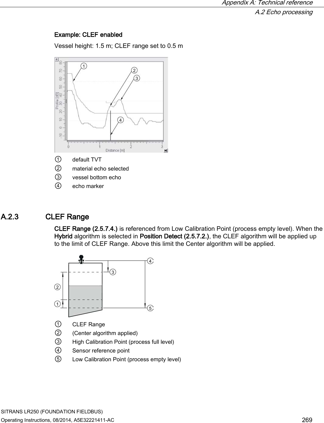
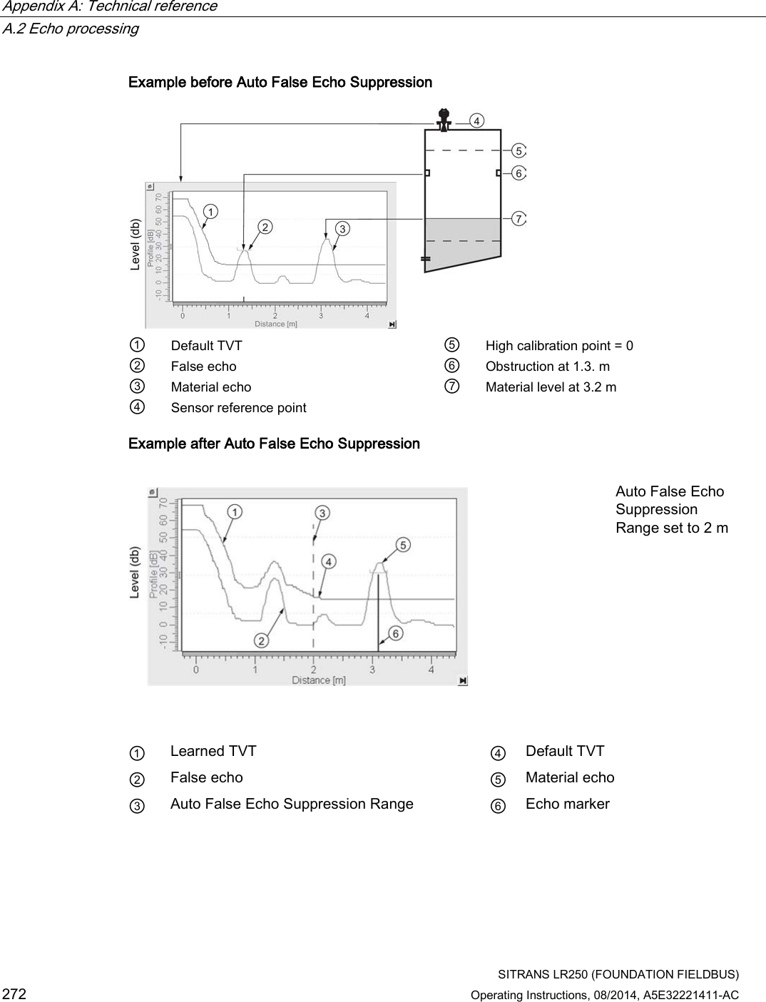
![Appendix A: Technical reference A.2 Echo processing SITRANS LR250 (FOUNDATION FIELDBUS) Operating Instructions, 08/2014, A5E32221411-AC 267 ① default TVT ② echo profile ③ material level ④ echo marker The device characterizes all echoes that rise above the TVT as potential good echoes. Each peak is assigned a rating based on its strength, area, height above the TVT, and reliability, amongst other characteristics. Algorithm (2.5.7.1.) The true echo is selected based on the setting for the Echo selection algorithm. Options are true First Echo, Largest Echo, or best of First and Largest. Position Detect (2.5.7.2.) The echo position detection algorithm determines which point on the echo will be used to calculate the precise time of flight, and calculates the range using the calibrated propagation velocity [see Propagation Factor (2.5.3.) for values]. There are three options: ● Center ● Hybrid (Center and CLEF) ● CLEF (Constrained Leading Edge Fit) Center](https://usermanual.wiki/Siemens-Canada-Siemens-Milltronics-Process-Instruments/LR250.User-Manual-4/User-Guide-2277919-Page-125.png)
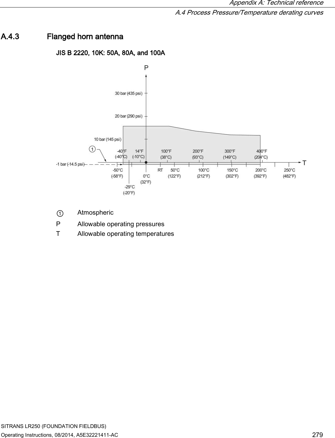
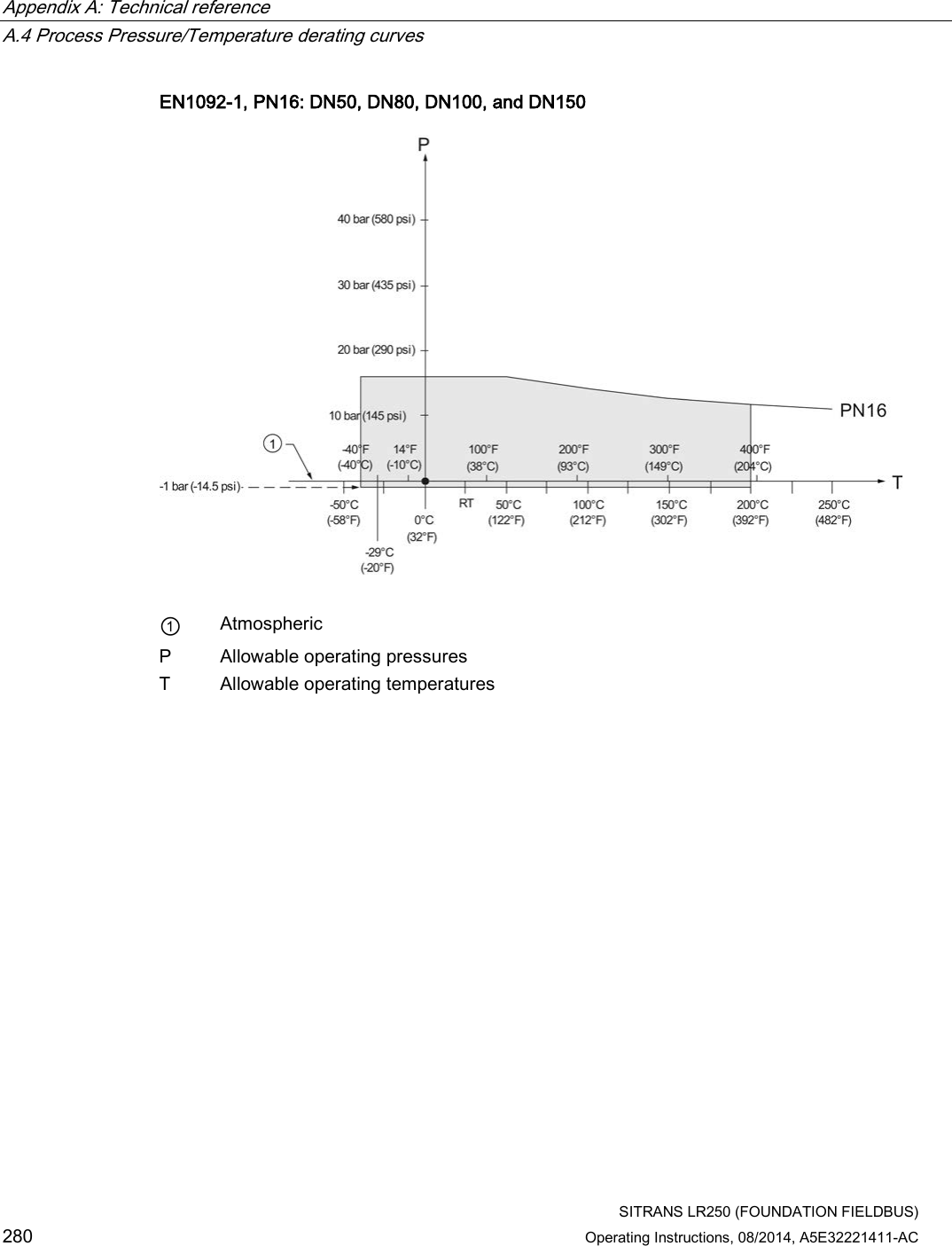
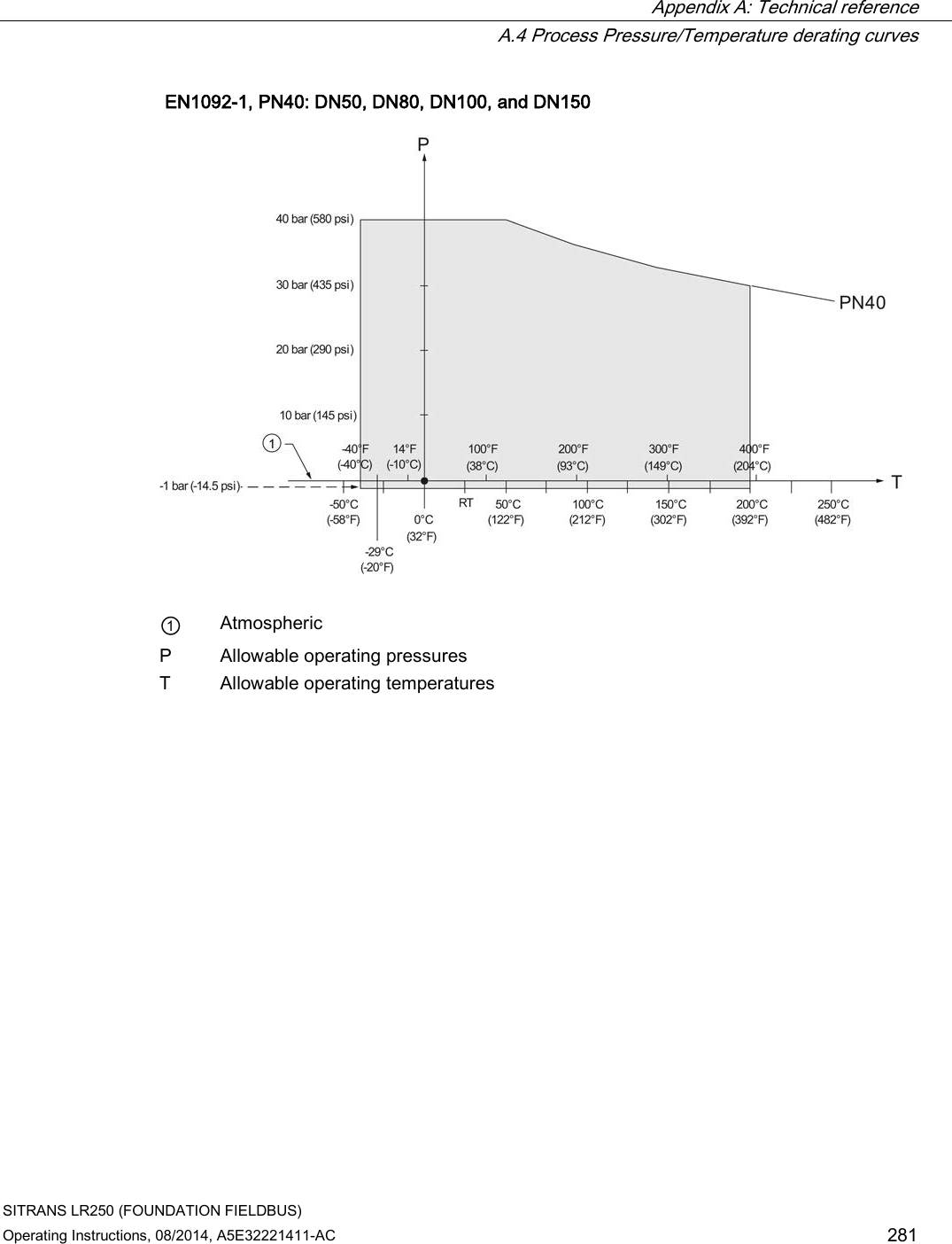
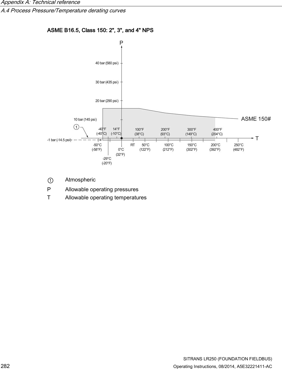
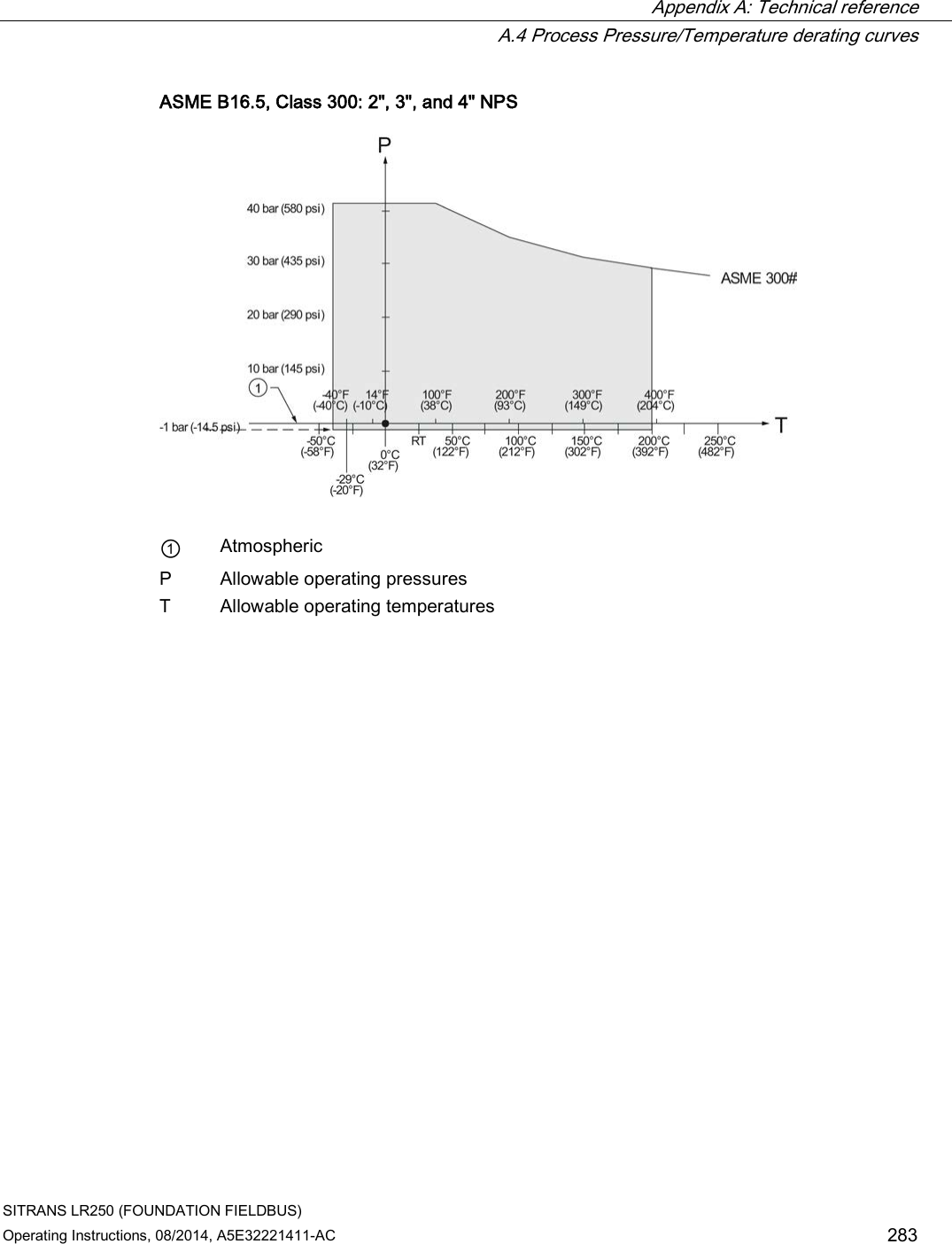
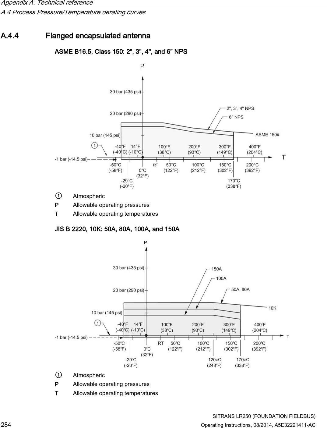
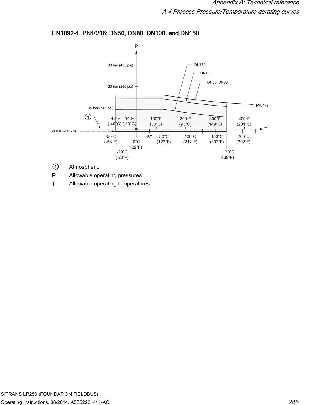
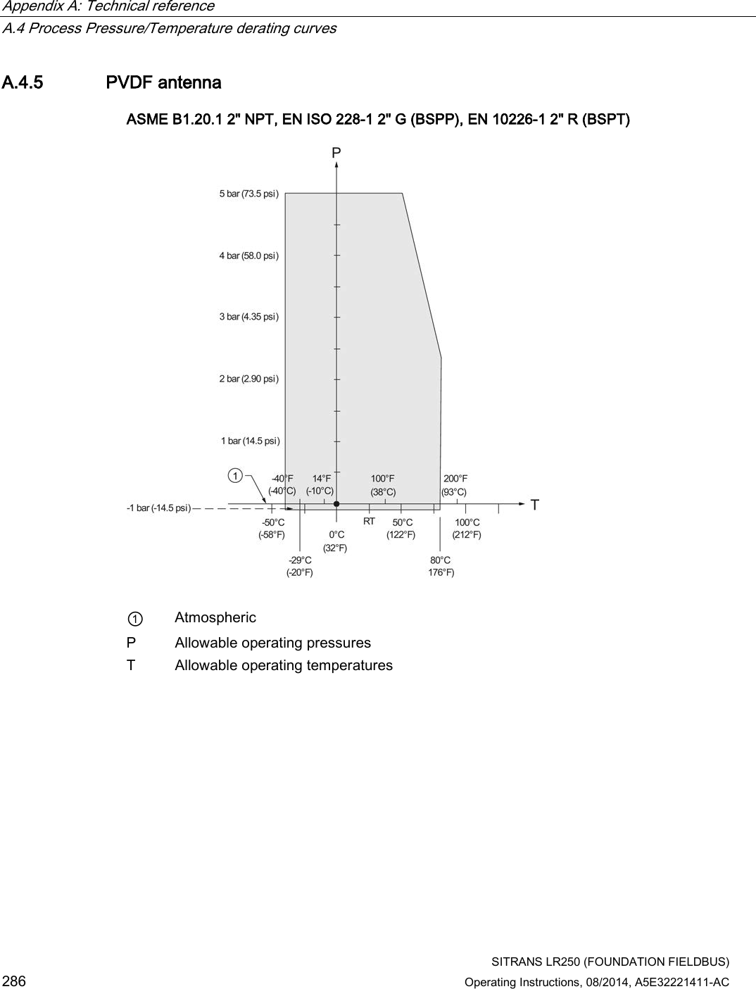
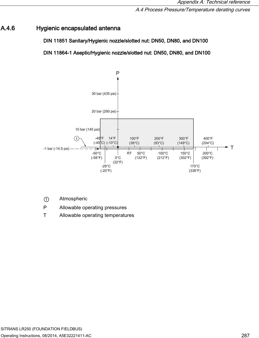
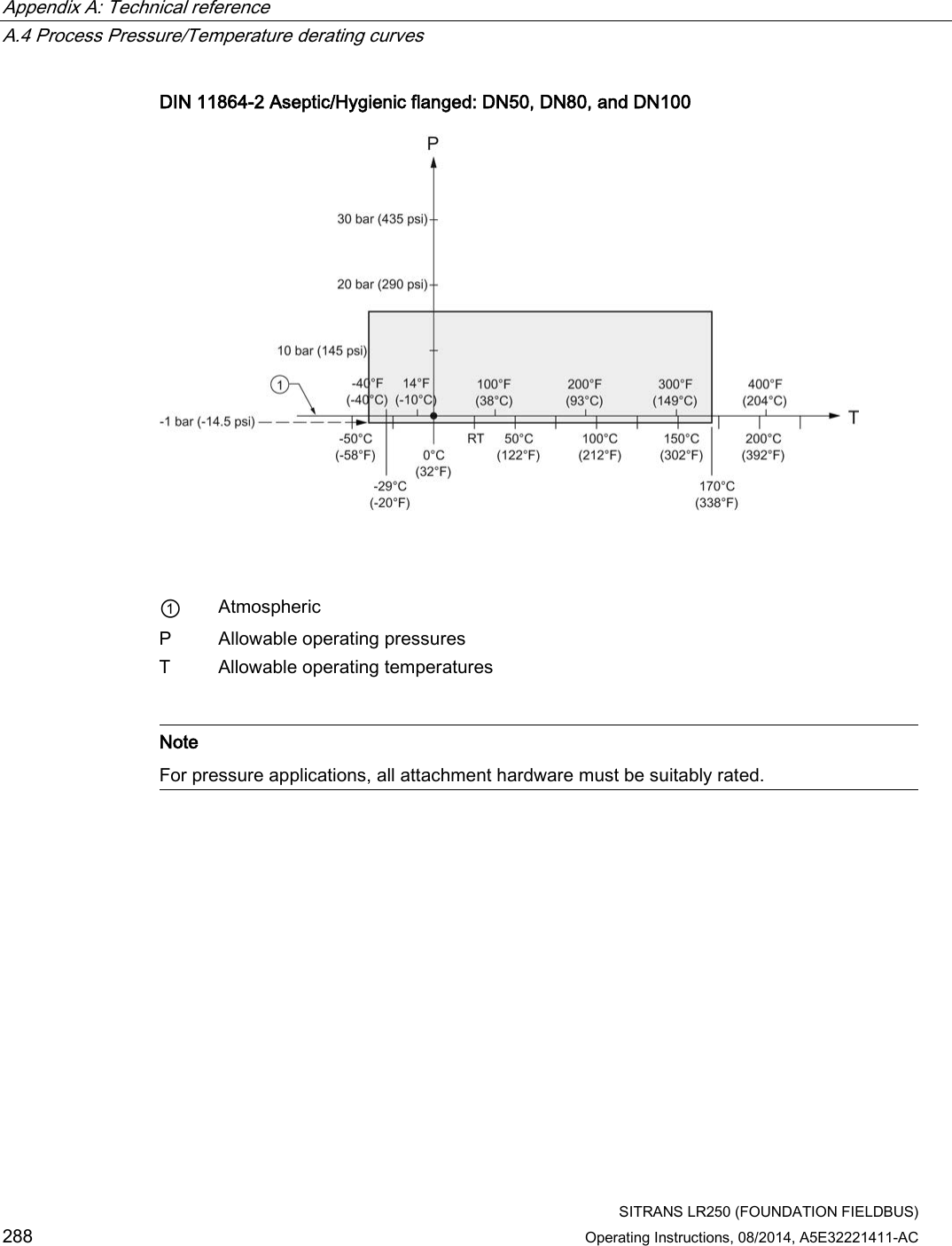
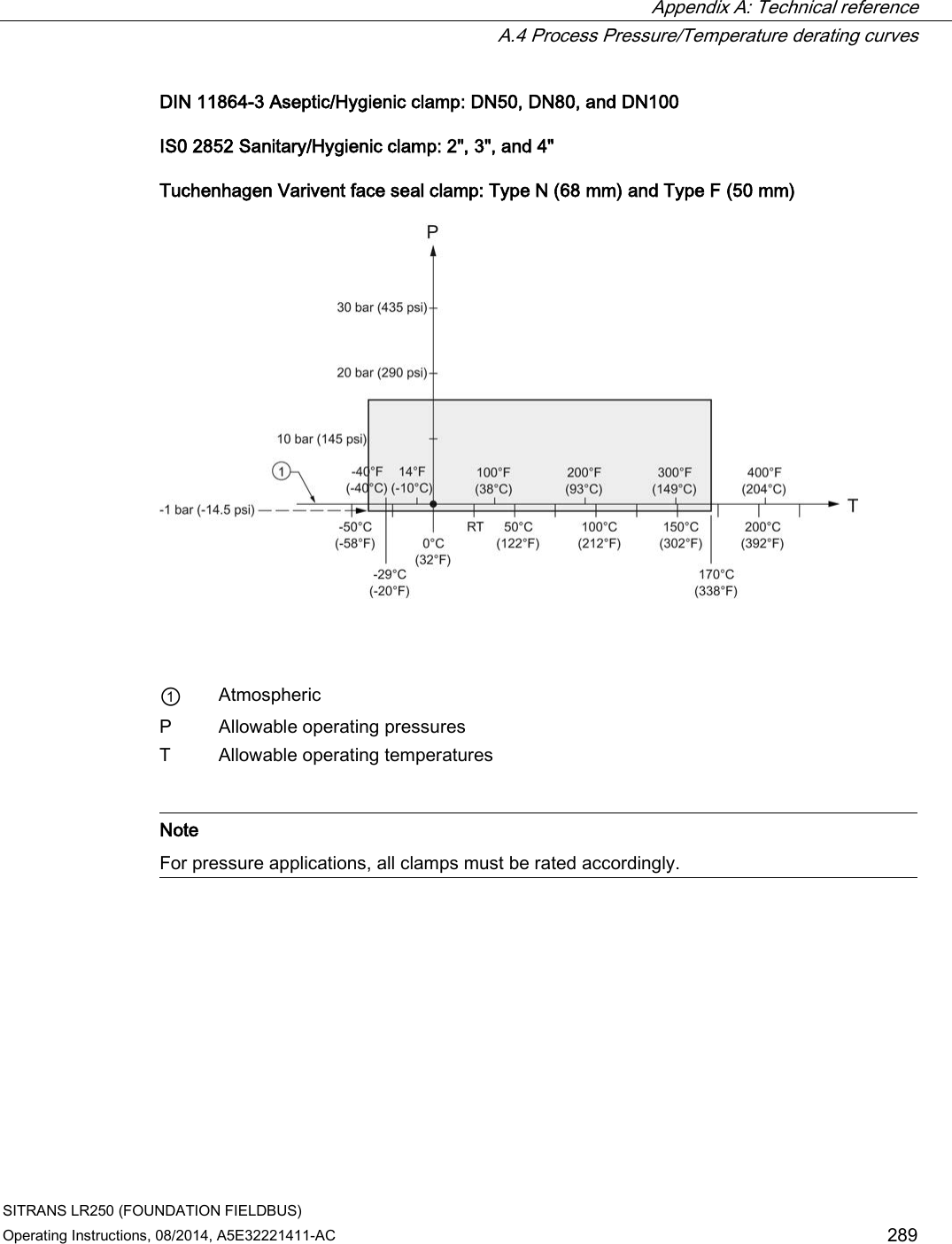
![Appendix A: Technical reference A.4 Process Pressure/Temperature derating curves SITRANS LR250 (FOUNDATION FIELDBUS) 278 Operating Instructions, 08/2014, A5E32221411-AC A.4.2 Horn antenna 1.5", 2" and 3" [NPT, G (BSPP), R (BSPT)] Threaded Versions ① Atmospheric P Allowable operating pressures T Allowable operating temperatures](https://usermanual.wiki/Siemens-Canada-Siemens-Milltronics-Process-Instruments/LR250.User-Manual-4/User-Guide-2277919-Page-136.png)

![SITRANS LR250 (FOUNDATION FIELDBUS) Operating Instructions, 08/2014, A5E32221411-AC 291 Appendix B: Communications via Foundation Fieldbus B SITRANS LR250 (Foundation Fieldbus) is an FF (H1) device of Class 31PS, and 32L. It supports publish and subscribe functionality as well as Backup LAS functionality. The full range of SITRANS LR250 functions is available only over an FF network. Foundation Fieldbus (FF) is an open industrial protocol. Full details about FF can be obtained from: Foundation Fieldbus (http://www.fieldbus.org/) For details on the use of Foundation Fieldbus protocol with Siemens FF level instruments, see manual Foundation Fieldbus for Level Instruments (7ML19985MP01). The manual is available on the CD of Siemens manuals, included in the box with your Siemens level instrument, or for other Siemens level measurement manuals, go to: Siemens level (http://www.siemens.com/level) Look under Level Measurement. B.1 Field Communicator 375 (F375) This device supports Field Communicator 375 (FC375). The FC375 menu structure is very similar to the menu structure for AMS Device Manager [see AMS Menu Structure (Page 79).]](https://usermanual.wiki/Siemens-Canada-Siemens-Milltronics-Process-Instruments/LR250.User-Manual-4/User-Guide-2277919-Page-149.png)